metodologia software - ii plantillas volere y uml
DESCRIPTION
Uml raptor y javaTRANSCRIPT

Sistemas IIPlantillas
Fabián Andrés Giraldo
COD:1800026

Plantillas
2
Requirement Shell
Requirement No.: Requirement Type: Use Cases:
Description:
Rationale:
Source (Originator):
Fit Criterion:
Customer Satisfaction Rating: Customer Dissatisfaction Rating:
Priority: (Must Have, Should have, Could have , want have)
Dependencies: Conflicts:
History: Supporting Materials:

Test Name: Test Case 2:
Description:
Requirement(s):
Prerequisites:
Setup: Tester must point to Mock P drive in test environment. Verify that the most recent file is currently in Trademarks\FAST 2.1\BIN\Fast Application.exe of the current CM Build. Create a desktop shortcut of the FAST executable file from Mock P and launch the FAST exe.Map to the TICRS drive(s):
3

4

Plantillas
Actor Cards
5
Actor Specification
Actor Name:
Type: (Primary/Secondary) Personality: (I, E, R or F) Abstract: (Yes/No)
Role Description:
Actor Goals:
Use Cases Involved with:

Plantillas
• Use Case Diagram
6
ATM System
Customer
Bank Manager
ATM Service Rep
Customer Accounts System
Withdraws Funds
Makes Deposits
Manages Account
Inquires Customer
Activity
Monitors ATM
Status
Replenishes Cash
Upload Customer
Transaction
Data
ATM System
Customer
Bank Manager
ATM Service Rep
Customer Accounts System
Withdraws Funds
Makes Deposits
Manages Account
Inquires Customer
Activity
Monitors ATM
Status
Replenishes Cash
Upload Customer
Transaction
Data

Plantillas
Elaborated Use Case Form w/Business Steps
(This is the same form as the prior Elaborated Use Case
form, but it has two columns where you can differentiate
system steps from business steps. Use cases normally
only have system steps, but describing business steps may
provide important context information for your application. It
is important that developers can differentiate system
actions from business actions in your use cases.)
7

Plantillas
8
Use Case ID (prefix your Use Case IDs with UC, to distinguish them from other models)
Use Case
Elaboration PhaseElaborated use case
Actors
Description(brief)
System Steps Business Steps
Pre-conditions
Flow of Events(include conditional flows here as they occur)
1.2.3. If xxx
1.4. Else
1.2.
5.etc.
1.2.3. If xxx
1.4. Else
1.2.
5.etc.
Post-conditions
Alternative Flows
(briefly describe alternative flows here for base Use Cases; extend this into complete flow of events for Elaborated Use Cases, either here or in the next template)
Priority (High, Medium or Low)
Non-Functional Requirements
(only those associated with this use case, if any)
Assumptions
Outstanding Issues
Source

Plantillas
Use Case Form for Alternative Flows
(An Alternative Use Case MUST be associated with an existing Elaborated Use
Case)
9
Use Case ID (same ID as the base Use Case ID, but with suffix A1, A2, etc., for each alternative flow Use Case)
Use Case
Elaboration Phase (indicate whether it’s initial, base or elaborated use case)
Actors
Description (brief)
Insertion Point (step in Base Use Case where this alternative flow should be inserted)
Pre-conditions (clearly indicate under which conditions the alternative flow is triggered)
Alternative Flow of Events 1.2.3.4.5.
Post-conditions
Priority (High, Medium or Low)
Non-Functional Requirements
(only those associated with this use case, if any)
Assumptions
Outstanding Issues
Source
Plantillas
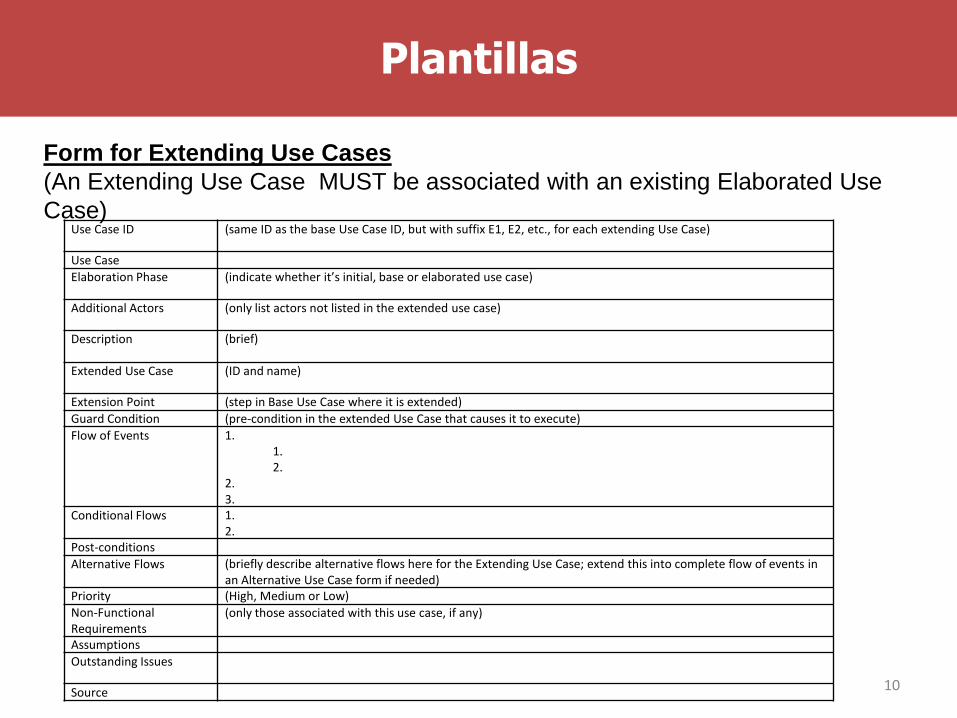
Form for Extending Use Cases
(An Extending Use Case MUST be associated with an existing Elaborated Use
Case)
10
Use Case ID (same ID as the base Use Case ID, but with suffix E1, E2, etc., for each extending Use Case)
Use Case
Elaboration Phase (indicate whether it’s initial, base or elaborated use case)
Additional Actors (only list actors not listed in the extended use case)
Description (brief)
Extended Use Case (ID and name)
Extension Point (step in Base Use Case where it is extended)
Guard Condition (pre-condition in the extended Use Case that causes it to execute)
Flow of Events 1.1.2.
2.3.
Conditional Flows 1.2.
Post-conditions
Alternative Flows (briefly describe alternative flows here for the Extending Use Case; extend this into complete flow of events in an Alternative Use Case form if needed)
Priority (High, Medium or Low)
Non-Functional Requirements
(only those associated with this use case, if any)
Assumptions
Outstanding Issues
Source

Plantillas
Form for Included Use Cases
(An Included Use Case is generic and can be re-used and included in any other
Use Case, so it does not need to be associated with a specific Use Case)
11
Use Case ID (prefix your Use Case IDs with IUC, to distinguish them from other Use Cases)
Use Case
Elaboration Phase (indicate whether it’s initial, base or elaborated use case)
Description (brief)
Including Use Cases (list all Use Cases that use this Included Use Case)
Pre-conditions
Flow of Events 1.1.2.
2.3.
Conditional Flows 1.2.
Post-conditions
Alternative Flows (briefly describe alternative flows here for the Included Use Case; extend this into complete flow of events in an Alternative Use Case form if needed)
Priority (High, Medium or Low)
Non-Functional Requirements (only those associated with this use case, if any)
Assumptions
Outstanding Issues
Source

12
R1
R2
R3
R4
R5
U1 U2 U3 U4
Use cases
Req
uirem
ents

Plantillas
• Desing
Diagrama de Estructura
13

• Diagrama de Flujo por cada módulo del diagrama de
Estructura.
14

15

Plantillas
• Testing
16
Test Name
Operator Action (Entered) Expected Results Observed Results
Pass/Fail
Ejercicio
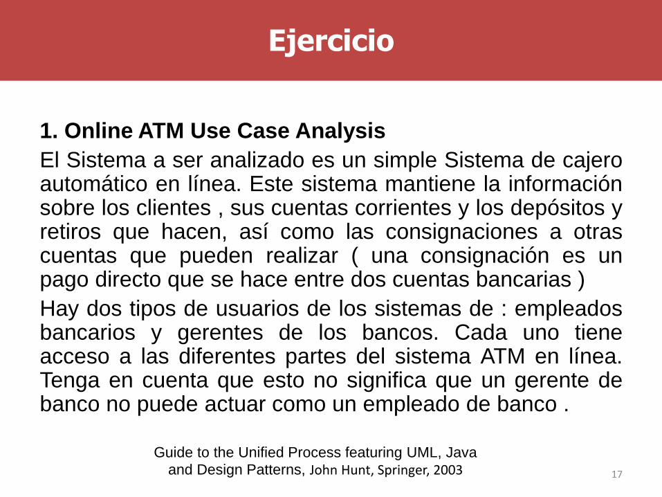
1. Online ATM Use Case Analysis
El Sistema a ser analizado es un simple Sistema de cajeroautomático en línea. Este sistema mantiene la informaciónsobre los clientes , sus cuentas corrientes y los depósitos yretiros que hacen, así como las consignaciones a otrascuentas que pueden realizar ( una consignación es unpago directo que se hace entre dos cuentas bancarias )
Hay dos tipos de usuarios de los sistemas de : empleadosbancarios y gerentes de los bancos. Cada uno tieneacceso a las diferentes partes del sistema ATM en línea.Tenga en cuenta que esto no significa que un gerente debanco no puede actuar como un empleado de banco .
17
Guide to the Unified Process featuring UML, Java
and Design Patterns, John Hunt, Springer, 2003

Ejercicio
Tenga en cuenta cada una de las preguntas que se considera a continuación:
• ¿Cuáles son las principales tareas del empleado ? Empleados delBanco desearán saber la cantidad de dinero en una cuenta bancaria .Ellos también quieren tener la posibilidad de depositar y retirar dinerode los clientes . En el caso de la retirada de dinero se debe tener encuenta si hay fondos suficientes en la cuenta del cliente .
• ¿El empleado tiene que leer / escribir / cambiar cualquiera de lainformación del sistema ? Como se trata de un sistema bancario , noqueremos que los empleados sean capaces de cambiar directamentedatos de la cuenta del cliente (sólo se permite a un administrador parahacer eso ) . Sin embargo, nosotros queremos que sean capaces dedepositar y retirar fondos que indirectamente va a cambiar los datos deun cliente. No queremos que los empleados sean capaces de cambiarel saldo total del cliente, pero sí queremos que sean capaces deacceder a él . Además , queremos que un empleado sea capaz deimprimir extractos bancarios de un cliente.
18

Ejercicio
¿El empleado tiene que informar al sistema sobre los
cambios externos? En este sistema particular, la respuesta
es no . Sin embargo, en un sistema bancario real que
podríamos cambiar la información , como el cambio de
domicilio, el empleador o el estado marital. Nos gustaría
que el gerente sea capaz de cambiar el nombre del cliente.
•¿Desea que el empleado sea informado sobre los
cambios inesperados? Una vez más, debido a la
simplicidad de esta aplicación, la respuesta es no ; sin
embargo, en el sistema real , la respuesta no es tan clara .
19

Ejercicio
Se tiene planteado Interfaces gráficas como las mostradas
a continuación.
20

Ejercicio
21

Ejercicio
22

Ejercicio
23

Ejercicio
24

Ejercicio
25

Ejercicio
26

Ejercicio
Actividades
1. Identificar y escribir los requerimientos
2. Desarrollar la especificación de requerimientos.
3. Identificar los requerimientos de testing
4. Identificar los casos de uso y realizar la especificación
5. Completar la matriz de trazabilidad requerimientos vrs casosde uso.
6. Diseño.
1. Diagrama de Estructura
2. Diagrama de Flujo
7. Código en el lenguaje de Programación Java
8. Ejecución de casos de prueba.
27