methodology of safe hri - cordis
TRANSCRIPT

DELIVERABLE D2.3
Methodology of safe HRI
Contract number : 247772
Project acronym : SRS
Project title : Multi-Role Shadow Robotic System for Independent Living
Deliverable number : D2.3
Nature : R – Report
Dissemination level : PU – PUBLIC
Delivery date : PrM24
Author(s) : Gernot Kronreif – IMA
Partners contributed :
Contact : Gernot Kronreif
Integrated Microsystems Austria GmbH
Viktor Kaplan-Strasse 2
2700 Wiener Neustadt, Austria
E-mail: [email protected]
SRS
Multi-Role Shadow Robotic System for Independent Living
Small or medium scale focused research project (STREP)
The SRS project is funded by the European Commission under the 7th Framework Programme (FP7) – Challenges 7: Independent living, Inclusion and Governance Coordinator: Cardiff University
SRS
Multi-Role Shadow Robotic System for Independent Living
Small or medium scale focused research project (STREP)

SRS Deliverable 2.3 Due date: PrM24
FP7 ICT Contract No. 247772 1 February 2010 – 31 January 2013 Page 2 of 38
Executive Summary
The main goal of SRS is to promote the quality of life for elderly people through service robots. This target will be achieved in SRS project by delivering a user oriented robotic manipulator to prolong independent living. According to the EC “Directive for Machinery” a system like SRS “ … must be designed and constructed so that it is fitted for its function, and can be operated, adjusted and maintained without putting persons at risk when these operations are carried out under the conditions foreseen but also taking into account any reasonably foreseeable misuse thereof.” The aim of this deliverable thus is to discuss different ways of human-robot interaction with particular aspect of safety. Resulting from this analysis a methodology for the design and realisation of safe robot systems should be worked out. The formulation of this method is done in two directions. First of all the outlined methodology should be as general as possible in order to be used for service robots in different context. In addition, the elaborated guideline should be applied for the SRS robot system in particular. This document is structured as follows:
Safety aspects in the SRS project – a general overview
Different types of interaction in SRS
Related standards
A guideline for safe HRI
Application of the guideline for the SRS robot system
Outlook

SRS Deliverable 2.3 Due date: PrM24
FP7 ICT Contract No. 247772 1 February 2010 – 31 January 2013 Page 3 of 38
Table of Contents 1. Safety aspects in the SRS project – a general overview ...................................................................... 4
1.1 “Safety” as Integrated Topic in SRS ............................................................................................ 4
1.2 Scope of this Deliverable ............................................................................................................ 5
2. Different types of interaction in SRS ................................................................................................... 5
2.1 Physical Interaction between User and Robot ........................................................................... 5
2.2 Physical Interaction between Robot and Environment .............................................................. 5
2.3 Interaction between Local User and Robot excluding UI ........................................................... 6
2.4 Interaction between SRS Users and Robot via UI ....................................................................... 6
3. Related standards ................................................................................................................................ 7
4. A guideline for safe HRI ..................................................................................................................... 17
4.1 Intended Use ............................................................................................................................. 17
4.2 Essential Requirements............................................................................................................. 17
4.3 Risk Management Process ........................................................................................................ 23
4.4 Verification and Validation ....................................................................................................... 29
5. Application of the guideline for the SRS robot system ...................................................................... 31
5.1 SRS -- Intended Use ................................................................................................................... 31
5.2 SRS -- Essential Requirements .................................................................................................. 33
6. Summary and Outlook ....................................................................................................................... 37
6.1 Summary ................................................................................................................................... 37
6.2 Next steps for SRS Safety Management ................................................................................... 37

SRS Deliverable 2.3 Due date: PrM24
FP7 ICT Contract No. 247772 1 February 2010 – 31 January 2013 Page 4 of 38
1. Safety aspects in the SRS project – a general overview A robot like SRS inherently has the potential to damage goods or - even worse - harm humans. In particular in the environment of elderly people, who are possibly unable to cope properly with critical situations, the highest dependability standards have to be fulfilled. This deliverable aims to propose a methodology for a safe system design, in particular considering different aspects of Human-Robot-Interaction. Relevant international standards - domain-specific ones as well as generic ones - have been analysed with respect to their applicability for SRS. Based on this research, selected safety-related directives and requirements have been compiled into a set of design guidelines. The resulting methodology should not only be used by SRS, but are designed in such a general way to be applied also for future service robot systems.
1.1 “Safety” as Integrated Topic in SRS According to the “Description of Work” (DoW) of the SRS project, safety related issues are distributed to several tasks. The following picture describes the basic “safety loop” and shows the links to different tasks in SRS.
T2.5: SRS Safety Approaches
Safety Analysis Safety Measures
Standards(D1.2)
RequirementsScenarios(D1.1)
Safety Requirements
Risk Analysis
SRS PrototypeT5.3
Guidelines/Methodology(D2.3)
T4.3
User Interface(T2.4, T2.7)
Standards
Requirements(D2.2)
Final Report(D1.4, D4.1)
UI ImplementationT5.1
Usability EvaluationT2.6
Design Principles(D2.2)
Figure 1 – “Safety” in SRS project
There are two starting documents for the SRS system. Deliverable D1.1 includes the definition of the system requirements as well as the scenario description (and with that defines the “Intended Use” of the system). Deliverable D1.2 includes – beside of description of the State-of-the-Art of components and systems related to SRS – a first analysis of related standards and regulations. Based on the input documents and the related standards, a Safety Assessment procedure has been started as part of task T2.5 “Safety Approaches for Human-Robot-Interaction”. This procedure has been generalized and is being reported in the present deliverable D2.3 “Methodology of safe HRI”. Risk analysis procedure identifies particular risks and mitigation measures -- realisation of appropriate safety measures is the main activity in Task T4.3. Verification of selected “Essential Requirements” of the system (documented in this Deliverable) will be guided by the test procedure defined in this document and will be reported at project end in D1.4 (also including the final report from the Risk Analysis process). Description of selected realized safety measures finally will be part of the final version of Deliverable D4.1. Based on the project setup defined in the SRS-DoW, development of the three User Interfaces (UI_LOC, UI_PRI, UI_PRO) is a parallel process – connected to the system development via the risk analysis

SRS Deliverable 2.3 Due date: PrM24
FP7 ICT Contract No. 247772 1 February 2010 – 31 January 2013 Page 5 of 38
process. Deliverable D2.2 outlines the specific requirements for the User Interfaces as well as HRI design guidelines. Usability Evaluation (T2.6) as well as formulation of guidelines for remote-controlled service robots (T2.7) also can be seen as safety relevant tasks.
1.2 Scope of this Deliverable As there is no document planned in the SRS-DoW which describes safety specific issues of the SRS robot system in a more extended view, the present deliverable interprets the term “Human-Robot-Interaction” in a broader sense. As mentioned in chapter (2) of this document, the analysis described here is not limited to the SRS user interfaces UI_LOC, UI_PRI, and UI_PRO. The safety analysis rather includes desired and undesired physical interaction between user and robot and other input/output elements of the SRS system. The deliverable finally aims to outline a design methodology – i.e. a basic guideline – for a safe service robot system (and not “only” considering the interaction part of such a system) and also applies this guideline to selected problems of the SRS system design. Due to the timing of the deliverable some of the results – i.e. reporting of the application of the guideline to SRS – will be not included to this deliverable but to the final SRS reports in D1.4 (“Requirement specification of future remotely control service robot for home care”) and D4.1 (“Integrated report about SRS control programme and safety assurance”).
2. Different types of interaction in SRS As mentioned above, the term “Human-Robot-Interaction” (HRI) is being interpreted in a broader sense for this deliverable. The following types of “interaction” will be investigated and analyzed here:
• Intended and unintended physical interaction between user and robot • Intended and unintended physical interaction between robot and environment • Interaction between local user and robot, excluding “direct” interaction via UI_LOC • Interaction between different user types and robot via user interfaces UI_LOC, UI_PRI, UI_PRO
2.1 Physical Interaction between User and Robot Physical interaction between user and robot can be grouped into two classes: intended interaction and unintended interaction. For the SRS system, there is no direct physical interaction between user and robot (arm) planned. Objects for the planned “fetch and carry”-tasks are handed over the robot’s tray only. There is a chance of having an unintended physical interaction – i.e. in case of a collision between parts of the robot system and the user. Such a collision can be with the manipulator arm and/or with the robot’s moving platform, but also with other parts of the robot e.g. the foldable tray. Due to the combination of manipulator and mobile base the working space of the robot system cannot be determined. The risk of such collisions can be reduced by avoiding movement of the manipulator during movement of the platform, folding the arm in a parking position during movement, no direct physical interaction between user and SRS system, etc. Another possible collision might take place when the user is colliding with the not-moving SRS robot system. Such kind of collision cannot be avoided by the SRS safety system – hazard related to this kind of collision should be reduced by appropriate design of the robot (e.g. no sharp edges, soft materials, etc).
2.2 Physical Interaction between Robot and Environment Also this type of physical interaction can be grouped into two classes: intended interaction and unintended interaction. As the main purpose of the SRS system is to support the user by processing

SRS Deliverable 2.3 Due date: PrM24
FP7 ICT Contract No. 247772 1 February 2010 – 31 January 2013 Page 6 of 38
“fetch&carry”-tasks, direct physical interaction between robot (arm) and objects in the environment is a standard operation case. This type of interaction is supported by various sensor information and thus ideally should include no safety risk. However, the risk analysis of the interaction process will be required in order to analyse hazards resulting from erroneous task execution, e.g. caused by incomplete or wrong sensor readings. This must be considered especially due to the SRS learning functionality, because learning of new objects and grasping options might include additional risk. This already leads to the sub-group of unintended interaction between robot and environment, which again is taking place in case of collisions. As mentioned above, the main reason for such collisions is incomplete or wrong sensor information, in most cases combined with errors in automatic task execution or wrong user input in remote-controlled mode. One particular aspect is the collision between the (folded) robot arm and the moving robot platform, as such collisions might also influence the stability of the robot system (i.e. system might tilt unintentionally). Same situation might take place in case of a collision between the extended manipulator arm and the environment, e.g. during a manipulation task. Such a possible situation of reduced system stability needs to be investigated carefully during the risk analysis process.
2.3 Interaction between Local User and Robot excluding UI There will be additional interaction between the local user and the SRS robot system beside the main interaction via UI_LOC. The robot display function, for example, will inform the local user about the current operating mode (automatic mode or remote-controlled mode), signals the start of any movement so that the user is prepared, inform about any existing error situation, etc. This user information is being implemented by visual as well as acoustic output. Another type of user interaction (in a very broad sense) is the way the robot is approaching the user, e.g. the speed of approach, the direction, as well as the stopping distance. Interaction from the user to the robot system mainly will take place via UI_LOC. In addition, basic robot actions will be started by gesture control. Regarding safety, there is an emergency stop button located directly on the robot. Gesture recognition is not used for any safety related commands.
2.4 Interaction between SRS Users and Robot via UI Interaction between SRS users and SRS robot system via UI is the standard way of (bidirectional) communication. According to the system setup described in D1.1 and D2.2 there are three different UIs used in SRS:
• UI_LOC: with this interface the local user can start different SRS tasks and receives basic feedback about the current system state. In case of an exceptional situation, the functionality for solving the problem is limited to stopping the procedure or hand over control to one of the remote-operators. Thus the safety risk connected to this way of interaction is relatively low.
• UI_PRI: with this remote-control interface the user (“private care-giver”) already can use basic functions for resolving exceptional cases. There is no functionality available for controlling the robot in its basic functions so that the safety risk connected to UI_PRI is moderate. It must be considered, however, that the user of UI_PRI has no direct sight to the complete scenery and that a safe operation of the robot very much relies on the correctness of sensor information and availability of different safety mechanisms and strategies. UI_PRI is equipped with a stop function accessible at each screen of the interface. Due to the wireless transmission of this stop signal and possible communication delays this stop function can not be considered as an emergency stop functionality.
• UI_PRO: this remote-control interface – operated by trained “professional care-givers” – finally allows control of each basic function of the robot. In order to solve all possible exceptional cases, such command situation also might ignore/overrule particular safety mechanisms and sensor information. Part of the SRS safety concept thus is that the local user should be outside of the

SRS Deliverable 2.3 Due date: PrM24
FP7 ICT Contract No. 247772 1 February 2010 – 31 January 2013 Page 7 of 38
robot working space – whenever possible -- during this operation mode. Remote-control users operating UI_PRO will be supported by different sensor systems as well as “virtual cameras” showing the current scenery from different viewpoints. It must be added at this point, that such virtual cameras are based on a 3D model of the environment; the proper use of this functionality thus very much relies on the completeness of this model. Similar to UI_PRI there are also real images (or video stream respectively) about the scenery (taken by the on-board camera of the robot and thus limited in viewpoints) as well as sensor information in order to provide additional information. Also UI_PRO includes emergency stop buttons – but also for this interface the wireless nature of the connection and possible communications delays are not allowing to consider this stop command as an emergency stop function. There will be communication watchdogs which automatically stop robot movement in case of communication problems, but no “real-time” reaction to hazardous situations with both UI_PRI and UI_PRO is possible.
3. Related standards Even if standards usually don’t describe how to make a system like SRS “safe”, they at least specify which safety related issues need to be taken under consideration and thus are giving valuable support for the design of a safe system. Deliverable D1.2 “Technology Assessment” already describes some of existing standards related to the SRS setup. For the sake of completeness, this chapter once more outlines the most appropriate standards and describes the most essential requirements set in these standards, particularly related to SRS, in more detail. In addition to existing standards, a setup like the SRS robot system also needs to comply to the “Directive on Machinery” (2006/42/EG)12. The main motivation of this directive is that “… accidents caused directly by the use of machinery can be reduced by inherently safe design and construction of machinery and by proper installation and maintenance …” which clearly confirms the importance of system safety. According to the directive, the term “machinery” is defined as “… an assembly, fitted with or intended to be fitted with a drive system other than directly applied human or animal effort, consisting of linked parts or components, at least one of which moves, and which are joined together for a specific application ….”. In the following, some of the key statements of the directive will be cited and the relation to the design methodology outlined in this deliverable will be described. (12) The putting into service of machinery within the meaning of this Directive can relate only to the
use of the machinery itself for its intended purpose or for a purpose which can reasonably be foreseen.
As can be seen in paragraph (12) of the directive, the definition of the “intended use” of the machinery is of paramount importance. Failure to adequately define the intended use of a system at the beginning of a project has been, and continues to be, universally recognized as one of the most frequent reasons
1 It should be mentioned at this point, that according to the scope of directive 2006/42/EC, any „... machinery
specially designed and constructed for research purposes for temporary use in laboratories ...“ is explicitly not subject to the requirements set therein. On the other hand, the purpose of any application oriented research and thus also of this deliverably is the design and realisation of systems for real use in realistic environment, with real users. In the light of such research goals, the consideration of related directives and standards is highly recommended. 2 For certain household devices there is an overlapping between 2006/42/EG „Directive on Machinery“ and
2006/95/EG „Directive on Electrical Equipment Designed for Use within Certain Voltage Limits“. After analysis of this directive the „Directive on Machinery“ finally has been evaluated as more relevant for systems like SRS.

SRS Deliverable 2.3 Due date: PrM24
FP7 ICT Contract No. 247772 1 February 2010 – 31 January 2013 Page 8 of 38
for later problems in the design and/or validation phase. There is, however, no clear definition about the content of such an “intended use” definition available in general. The content of the intended use description proposed in this deliverable is based on standard EN ISO 14971 (“Medical devices — Application of risk management to medical devices”) and should include:
• Description of the main function(s) of the system. What is the main service provided by the system?
• In what way(s) might the medical device be deliberately misused? • What is the role of the system for assisting the user? • Is there any direct physical interaction between user and robot? • To what mechanical forces will the robot be subjected? • Description of the users of the system, their mental and physical abilities, the required
functionalities and knowledge. Does use of the robot require special training or special skills? • Is there any foreseen system functionality in order to compensate for user’s injury or disability?
(REMARK: in such a case it must be evaluated if the described system rather needs to be treated as a “Medical Device”)
• Is the user controlling the system? Is successful application of the robot critically dependent on human factors such as the user interface?
• Information about the environment of use. Is the robot changing or influencing the environment?
• Who is installing the system? What are the requirements concerning maintenance and system calibration?
(14) The essential health and safety requirements should be satisfied in order to ensure that machinery
is safe; these requirements should be applied with discernment to take account of the state of the art at the time of construction and of technical and economic requirements.
Annex 1 of the Directive gives a list of Essential Health and Safety Requirements (referred to as EHSRs) to which machinery must comply where relevant. The purpose of this list is to ensure that the machinery is safe and is designed and constructed so that it can be used, adjusted and maintained throughout all phases of its life without putting persons at risk. A risk assessment must be carried out to determine which EHSRs are applicable to the equipment under consideration. The EHSRs in Annex 1 of the directive provides a hierarchy of measures for eliminating the risk: (1) Inherently Safe Design—where possible the design itself will prevent any hazards. Where this is not possible (2) Additional Protective Measures, e.g., guards with interlocked access points, non-material barriers such as light curtains or other sensors for collision detection/avoidance but also alarms should be used. Any residual risk which cannot be dealt with by the above methods must be contained by (3) Personal Protective Equipment and/or Training. The machine supplier must specify what is appropriate. Suitable materials should be used for construction and operation. Controls and control systems must be safe and reliable. Machines must not be capable of starting up unexpectedly and should usually have one or more emergency stop devices fitted. Failure of a power supply or control circuit must not lead to a dangerous situation. Machines must be stable and capable of withstanding foreseeable stresses. They must have no exposed edges or surfaces likely to cause injury. Electrical and other energy supply hazards must be prevented. There must be minimal risk of injury from temperature, explosion, noise, vibration, dust, gases or radiation. There must be proper provisions for maintenance and servicing. Sufficient indication and warning devices must be provided. Machinery shall be provided with instructions for safe installation, use, adjustment etc. As the definition of the EHSRs is very general and must fit to any machinery, not all requirements are applicable for a service robotic system like SRS. For the guideline outlined in this deliverable a new (reduced) set of “Essential Requirements” thus has been worked out, which is based on the EHSRs of the

SRS Deliverable 2.3 Due date: PrM24
FP7 ICT Contract No. 247772 1 February 2010 – 31 January 2013 Page 9 of 38
“Machinery Directive” as well as of the “Medical Devices Directive” (93/42/EEC). This list is detailed in chapter (4) of this deliverable. (15) Where the machinery may be used by a consumer, that is to say, a non-professional operator, the
manufacturer should take account of this in the design and construction. The same applies where a machine is normally used to provide a service to a consumer.
The statement above is a very import aspect for any service robot system, especially for SRS. At least two of the three SRS user groups, i.e. the “local user” as well as the “private RC operator” must be considered as “non-professional operator”. There must be a particular attention relating to wrong input and wrong system “understanding” during the risk analysis process – in particular in terms of identification of hazardous system behaviour and appropriate reaction to such situations. (19) In view of the nature of the risks involved in the use of machinery covered by this Directive,
procedures for assessing conformity to the essential health and safety requirements should be established.
In order to fulfil this requirement, a set of tests must be designed and performed in order to verify the conformity to essential requirements as well as the appropriateness of any mitigation measure identified during the risk analysis process. A detailed description of the “validation&verification” process and templates for test design and reporting are included in chapter (4) of this deliverable. (23) The manufacturer or his authorised representative should also ensure that a risk assessment is
carried out for the machinery which he wishes to place on the market. For this purpose, he should determine which are the essential health and safety requirements applicable to his machinery and in respect of which he must take measures.
See above. A risk management procedure must be integrative part of the system development. Any possible hazardous situation and the related risk must be evaluated – measures for risk reduction (“mitigation measurements”) must be identified. In more general, methods for risk management are defined in ISO 14121 (“Safety of machinery – Principles of risk assessment”). As the difference between this standard and ISO 14971 (“Medical devices -- Application of risk management to medical devices”) is relatively small – especially concerning the intended use of the SRS robot system, which in some aspects comes closer to a medical system rather than to a more general “machine” – the procedure outlined in this document is following ISO 14971. ISO 10218-1 - Robots for industrial environments -- Safety requirements -- Part 1: Robot ISO 10218-1 is replacing the older standards ISO 10218 and EN775 and specifies requirements and guidelines for the inherent safe design, protective measures, and information for use of industrial robots. It describes basic hazards associated with robots, and provides requirements to eliminate or adequately reduce the risks associated with these hazards. ISO 10218-1 does not apply to non-industrial robots like SRS but some basic safety principles are also useful for such service robotic systems. Especially regulations related to operating modes “programming” and “maintenance” show common problems to a service robot system because these modes of an industrial robot also include persons in the working area of the robot and the possibility of unintended robot movement due to programming errors. Safety principles to be transferred to service robots thus include the definition of a maximum TCP-speed, the use of emergency stop buttons, and the need to have (permanent) confirmation for robot movement (especially for robot movements when the operator is within the working area of the robot). In addition to the aforementioned standards, ISO 10218-1 also is related to assistive robot systems (referred to as

SRS Deliverable 2.3 Due date: PrM24
FP7 ICT Contract No. 247772 1 February 2010 – 31 January 2013 Page 10 of 38
“collaborative operation” and “collaborative workspace”), which further includes usable input for service robotic systems. Some of the most essential requirements from this standard (already partly adapted to SRS) are:
• exposure to hazards caused by components such as motor shafts, gears, drive belts, or linkages shall be prevented;
• loss of, or variations in power shall not result in a hazard. Re-initiation of power shall not lead to any motion. End-effectors shall be designed and constructed so that loss or change of electrical, hydraulic, pneumatic or vacuum power shall not result in a hazard;
• isolation of any electrical, mechanical, hydraulic, pneumatic, chemical, thermal, potential, kinetic or other hazardous energy source shall be provided;
• the design and construction of the robot shall be in accordance with IEC 61000 to prevent hazardous motion or situations due to the effects of electromagnetic interference (EMI), radio frequency interference (RFI) and electrostatic discharge (ESD);
• safety-related control systems shall meet the following criteria: a) a single fault in any part of the safety-related control system shall not lead to the loss of the
safety function; b) whenever reasonably practicable, the single fault shall be detected at or before the next
demand upon the safety function; c) when the single fault occurs, the safety function is always performed and a safe state shall
be maintained until the detected fault is corrected; d) all reasonably foreseeable faults shall be detected;
• the speed of the tool-centre point (TCP) shall not exceed 250 mm/sec, regardless of the operation mode of the robot system. Speed control shall be designed and constructed so that in the event of any single reasonably foreseeable malfunction, the speed of the mounting flange and of the TCP shall not exceed the reduced speed velocity limits;
• where a pendant control or other control device has the capability to control the robot from within the safeguarded space (REMARK: this is the case for controlling the SRS robot via UI_LOC), the following requirements shall apply: a) loss of communication (REMARK: for wireless pendant control) shall result in a protective
stop for the robot; b) REMARK: most of the other provisions from ISO 10218-1 cannot be realized in SRS (e.g.
permanent confirmation of robot movement, or three-point-emergency stop). These deviations from the standard need to be addressed at the risk analysis procedure accordingly!
• the robot shall maintain a separation distance from the operator (REMARK: whenever possible for the particular robot task). This distance shall be in accordance with ISO 13855. Failure to maintain the separation distance shall result in a protective stop. The position of the robot (REMARK: and of the operator) should be monitored permanently;
• the robot shall be designed to ensure either a maximum dynamic power of 80 W or a maximum static force of 150 N at the TCP (determined by the risk assessment). The robot design shall ensure that these values cannot be exceeded. When a control function is used to limit power and force, a protective stop shall be issued if the maximum values are exceeded;
• the robot shall be designed so that the axes are capable of being moved without the use of drive power in emergency or abnormal situations. Where practicable, moving the axes shall be carried out by a single person. Controls shall be readily accessible but protected from unintended operation;
• each robot or robot system shall be accompanied by an instruction handbook, which includes – among other information – instructions for safe operation, setting and maintenance including safe working practices, training required to achieve the necessary skill level of persons operating the equipment, information on the stopping time and distance or angle from initiation of stop

SRS Deliverable 2.3 Due date: PrM24
FP7 ICT Contract No. 247772 1 February 2010 – 31 January 2013 Page 11 of 38
signal of the three axes with the greatest displacement and motion, response time of detection of loss of communication, and others. For the complete list please see the chapter 6.2 of the standard.
One particular aspect is related to the emergency stop function. ISO 10218-1 very clearly requires such a control and specifies the system configuration after activation of this control. For SRS, and for many other similar service robot systems, an emergency stop button certainly can be (and will be) placed on the robot -- but the usability of this button could be rather limited. As mentioned above, SRS also will have stop functionality at the different UIs -- but due to wireless communication setup and possible communication delays this cannot be seen as an emergency button according to existing standards (e.g. IEC 60204-1:2005, 9.2.5.4.2). This issue needs particular attention in the risk analysis process! Similar deviations from the standard occur regarding limitation of working space (not applicable/useful in SRS because of mobile platform). Annex A of the standard finally gives a list of possible significant hazards, grouped into:
• Mechanical hazards • Electrical hazards • Hazards generated by neglecting ergonomic principles in the design process • Unexpected start-up, unexpected overrun/over speed • Failure of the power supply • Failure of the control circuit • Loss of stability, overturning of robot
This list is a good starting point for identification of system specific risks and should be analyzed in detail as part of the system design process. ISO 10218-2 - Robots for industrial environments -- Safety requirements -- Part 2: Robot systems and integration Whereas ISO 10218-1 is focusing to the robot as such, the second part of the standard is dealing with robot systems and the integration into more complex systems. As the SRS robot system actually can be seen as a stand-alone robot system standard ISO 10218-2 is not taken under consideration for SRS project. Please note that for other service robotic setups the standard could include relevant aspects – this needs to be analyzed on case-base. ISO 13849 – Safety of machinery – Safety-related parts of control systems – Part 1: General principles for design IEC 62061, Safety of machinery – Functional safety of safety-related electrical, electronic and programmable electronic control systems Both standards provide safety requirements and guidance on the principles for the design of safety-related parts of control systems. After comparing the two standards, IEC 62061 turns out to be more appropriate for service robot systems in general and SRS in particular, and this will be discussed in more detail. IEC 62061 deals with requirements for design, integration and validation of safety-related electrical, electronic and programmable electronic control systems (SRECS) for machines. It is applicable to control systems used, either singly or in combination, to carry out safety functions on machines that are not portable by hand while working, including a group of machines working together in a co-ordinated manner. In general the specifications for SRECSs are resulting from the risk analysis process. A detailed description of each safety function (SRCF) must include operational mode for the SRCF, a detailed description, priority of execution, desired reaction time, etc. Based on this specification the standard

SRS Deliverable 2.3 Due date: PrM24
FP7 ICT Contract No. 247772 1 February 2010 – 31 January 2013 Page 12 of 38
proposes a design and development process, according to which the safety function needs to be separated into single functional blocks, being detailed and assigned to SRECS subsystems, verified, developed and implemented. The standard also describes the process for estimation of the reached Safety Integrity Level (SIL) as well as of the probability for systematic and stochastic failures. ISO 13852 – Safety of machinery – Safety distances to prevent danger zones being reached by the upper limbs This standard gives values for safety distances to prevent danger zones being reached by the upper limbs of persons of 3 years of age and above without additional aid. The distances apply when adequate safety can be achieved by distances alone. As explicitly mentioned in the standard the selection of appropriate safety distance is subject to a preliminary risk assessment – maintaining safety distances listed in the standard thus must not be seen as a replacement for a detailed risk analysis process. The main part of the standard is related to safety fences and their correct geometrical design and is thus not applicable for SRS and similar service robot systems. ISO 13854 – Safety of machinery – Minimum gaps to avoid crushing of parts of the human body This international standard provides parameters based on values for hand/arm and approach speeds and the methodology to determine the minimum distances from sensing or actuating devices of protective equipment to a danger zone. ISO/DIS 13857 – Safety of machinery – Safety distances to prevent danger zones being reached by upper and lower limbs This international standard establishes values for safety distances in both industrial and public environments to prevent machinery hazard zones being reached. The safety distances are appropriate for protective structures. It also gives information about distances to impede free access by the lower limbs. It is applicable for people of 1,4m body height and above (this includes at least the 5th percentile of persons of 14 years and older). In addition, for upper limbs only, it provides information for children older than 3 years where reaching through openings needs to be addressed. The clauses of the international standard covering lower limbs apply when access by the upper limbs is not foreseeable according to the risk assessment. The safety distances are intended to protect those persons trying to reach hazard zones under the conditions specified. Similar to ISO 13852 the main part of ISO 13857 is related to safety fences and their correct geometrical design and is thus not applicable for SRS and similar service robot systems. ISO 14121 – Safety of machinery – Principles of risk assessment which has been recently replaced by ISO 12100 -- Safety of machinery - General principles for design - Risk assessment and risk reduction The primary function of this standard is to describe a systematic procedure for risk assessment so that adequate and consistent safety measures can be selected. Risk assessment is an essential part of the iterative process for risk reduction which should continue until adequate safety is achieved. Definitions used in Risk Assessment (see EN ISO 14121-1/ISO 12100 for full and complete definitions):
• Harm: Physical injury and/or damage to the health • Hazard: Potential source of harm • Hazardous Situation: Circumstance in which a person is exposed to at least one hazard • Risk: Combination of the probability of occurrence and the degree of severity of that harm

SRS Deliverable 2.3 Due date: PrM24
FP7 ICT Contract No. 247772 1 February 2010 – 31 January 2013 Page 13 of 38
• Risk Analysis: Combination of the specification of the limits of the machine, hazard identification and risk estimation
• Risk Assessment: Overall process comprising a risk analysis and risk evaluation • Risk Evaluation: Judgment, on the basis of risk analysis, of whether the risk reductions objectives
have been achieved The standard describes a risk assessment process, which includes:
• Hazard Identification from the characteristics of the robot and its environment • Risk Estimation by combining the severity of the harm and the probability of occurrence • Risk Evaluation to judge whether the risk reduction measures have been achieved
Figure 2 – “Risk Management” according to ISO 14121-1/ISO 12100
As mentioned above, the difference between EN ISO 14121-1/ISO 12100 and ISO 14971 (“Medical devices -- Application of risk management to medical devices”) is relatively small – especially concerning the intended use of the SRS robot system, which in some aspects comes closer to a medical system rather than to a more general “machine”. One additional aspect described in ISO 14971 is the process of “risk control”, in which decisions are made and measures implemented by which risks are reduced to specified levels. Given that, the risk management process outlined in this guideline is following ISO 14971. According to ISO 14971 the risk management can be shortly outlined as follows: After the definition of the intended use, the next main phase is the identification of system hazards, i.e. collecting all known and foreseeable hazards associated with the system in both normal and fault conditions. Reasonably foreseeable sequences or combinations of events that can result in a hazardous situation shall be considered and the resulting hazardous situation(s) shall be recorded. To identify hazardous situations which are not previously recognized, systematic methods may support the procedure. For each identified hazardous situation, the associated risk(s) shall be quantified by estimation of both probability of the occurrence of harm and the degree of severity of that harm. Any system used for qualitative or quantitative categorization of probability of occurrence and severity of harm shall be recorded in the risk management file. In the next step, it should be decided for each identified hazardous situation if risk reduction is required for the particular risk. Risk control measure(s), that are appropriate for reducing the risk(s) to an acceptable level, have to be identified. One or more of the following risk control options can be applied,

SRS Deliverable 2.3 Due date: PrM24
FP7 ICT Contract No. 247772 1 February 2010 – 31 January 2013 Page 14 of 38
in the priority order listed: (a) inherent safety by design; (b) protective measures in the system itself or in the manufacturing process; (c) information for safety. Finally, risk control measures have to be implemented and the effectiveness of the risk control measure(s) have to be verified. Results of verification procedure also shall be recorded in the risk management file. For residual risks that are judged acceptable, the manufacturer shall decide which residual risks to disclose and what information is necessary to include in the accompanying documents in order to disclose those residual risks. ISO 13482 – Robots and robotic devices – Safety requirements – Non-medical personal care robot As already mentioned in Deliverable D1.2 a new standard for non-medical service robots is in preparation phase and will be issued soon. Although this standard is not valid at the moment, the regulations set here are a very important input for the elaborated guideline and thus the standard is being discussed in more detail in the following. ISO 13482 takes particular care about the fact, that service robot systems very often require close human-robot-interaction and collaboration as well as physical human-robot contact. Basically, this new standard is structured similar to ISO 10218-1. Also ISO 13482 describes safety requirements as well as safety-related control system requirements. The standard has a special focus to three different types of personal care robots, namely “mobile servant robots”, “physical assistant robots”, and “person carrier robots”. For the present “safety guidelines” and for robots comparable to SRS the group of “mobile servant robots3” is the most appropriate one, and thus the following descriptions are focusing to this group only4. Some of the most essential requirements (already partly adapted to SRS) are:
• for battery operated robots protect users against accidental contact with the charging connectors; Charging systems should support correct charging and prevent hazards caused by overheating or wrong charging by automatically supervision;
• inherent safe design for energy storage and supply (e.g. extra-low voltage source); safeguarding and protective measures according to related standards (e.g. IEC 60204);
• the personal care robot and its parts shall be designed to avoid the potential for accidents that could cause crushing, cutting, or other severing injuries (e.g no sharp edges, consideration of ISO 13854 for the design of holes or gaps, proper design of the robot’s joint so that human body cannot be crushed when the joint is moved);
• no or limited emission of sound, hazardous vibrations, hazardous substances and fluids, non-ionising radiation (e.g. ultrasonic, laser, and light sources), or ionising radiation;
• compatibility against EMC (emission and immunity) cf IEC 61000-6-x; • risk of hazards due to the motion of the personal care robot shall be reduced to an acceptable
level. Robot components shall be designed, constructed, secured, or contained so that the risks of hazards caused by breaking or loosening, or releasing stored energy are reduced to acceptable levels, i.e. the robot shows sufficient mechanical stability;
• sufficient stability of the system during movement (design of mass distribution, appropriate design of the travel actuators);
• sufficient stability of the system during carrying loads (form fitting for the effector/load interaction, appropriate design of holders, placement areas, etc);
• sufficient stability in case of collision (collision between robot and any other obstacle should not cause instability of the robot);
3 A „mobile servant robot“ according to ISO 13482 is defined as a „ ... personal care robot that is capable of moving
freely to perform an intended task and/or handling objects (with or without a manipulator) ... „ 4 If the guidelines outlined here are beng used for any other robot setup – e.g. for person transport or
rehabilitation – the appropriate parts of ISO 13482 needs to be analysed accordingly!

SRS Deliverable 2.3 Due date: PrM24
FP7 ICT Contract No. 247772 1 February 2010 – 31 January 2013 Page 15 of 38
• a personal care robot which is capable of travelling autonomously shall have an obstacle avoidance capability with sufficient performance to ensure that the robot can avoid static obstacles in its travel path, or come to a safe stop without colliding with them. The response time of the sensing functions and the safety-related control system shall be capable of stopping the robot prior to impact between the robot structure and other mounted equipment and an obstruction being sensed in advance of the moving robot in the main direction of travel;
• an appropriate object detection function shall be incorporated within the personal care robot following a proper risk assessment for the intended use. The objects to be detected may include humans, animals, and other objects in the environment. Object detection devices shall be applied to ensure admissible distances or contact forces between a human or object and a robot;
• robot shall be designed with a means (on-board or off-board) of detecting the surface geometry and travel conditions, and shall be able to detect and judge whether it is capable of travelling through the detected paths or regions;
• force exerted on a human or surrounding objects by the robot or one of its parts shall be controlled within the maximum safe contact criteria such as force limits. The limits of the exerted force during unintended contact with a person may differ with application and shall be determined by risk assessment;
• robot control system shall be designed and constructed so that when the robot is placed under manual control or remote control, initiation of the robot motion or change of the local control selection from any other source shall be prevented;
• if there are more than one command devices used (REMARK: this is the case in SRS because of the three possible interfaces UI_LOC, UI_PRI, and UI_PRO), only one command device shall have control authority at any time. Before control can be transferred from one command device to another, an explicit changeover action shall be necessary. Each possible command control should always allow a controlled stop. It shall be clearly visible on all control devices, which one is currently active and which is not;
Beside of the aforementioned description of essential requirements, the standard also asks for definition of Performance Level (PL) or Safety Integration Level (SIL) for particular components, if they are used as safety measure. Examples for such components are: collision management, safety-related force limiting control, emergency stop, speed restriction and safety-related speed control, non-contact sensing, contact sensing, force restriction and safety-related force control, and others. The associated requirements from ISO 13849-1 or IEC 62061 shall be met. ISO 13482 is giving very detailed instructions for operation of the robot in different modes – which certainly is very relevant for a robot system like SRS. In chapter 6.8.7 the standard for example defines: A personal care robot shall be designed to operate in manual mode or operate in both manual and autonomous modes. (i.e., any robot designed for autonomous operation shall also be designed to operate under manual control.) Changeover between manual and autonomous modes shall be selected by a secure means that locks and exclusively enables only the selected mode; e.g. a key operated switch or other means that provides an equivalent security (i.e. supervisory control). The means of mode selection shall: • unambiguously indicate the selected operating mode; and • by itself not initiate robot motion or other hazards. Selected operating modes can be visual light signals, audible sound signals, vibrations or other signals so that the robot operator can easily recognise the mode selected. The control or operating mode selected must not override the emergency stop. When switching between modes, any suspended safety functions shall be returned to their full functionality. … For SRS setup, change of operation mode is part of the dialogue between local user and remote operator or of the dialogue between UI_LOC and UI_PRI/UI_PRO in particular. In order to meet the

SRS Deliverable 2.3 Due date: PrM24
FP7 ICT Contract No. 247772 1 February 2010 – 31 January 2013 Page 16 of 38
requirements set in the related standard, there must be a clear and documented process for this mode switch. Similar to ISO 10218 Annex A of the standard finally gives a list of possible significant hazards, grouped into (already adapted to robots like SRS):
• Mechanical hazards -- gravity, stability -- moving elements (REMARK: including clamping hazard between moving parts and non-
moving parts of the robot or gaps with variation of size during operation) -- mobility of the entire device -- rotating parts -- sharp edges
• Electrical hazards -- electromagnetic hazards -- electrostatic hazards -- live parts, terminals of battery -- overload, overheating -- short circuit -- parts becoming live due to fault conditions (REMARK: electric safety) -- hazards caused by insufficient power supply (REMARK: not included in the original list)
• Thermal hazards • Hazards due to noise (REMARK: emission of sound) • Hazards due to vibration • Radiation hazards (REMARK: especially regarding emission of IR light, laser, etc from sensors) • Material (REMARK: material cover, ability to burn, etc) • Ergonomic hazards
-- visibility of indicators, etc -- posture (especially for control console) -- hazards caused by mental/cognitive overload (REMARK: not included in the original list)
• Hazards related to operational environment -- moisture, liquids (REMARK: e.g. spoiling liquid over robot) -- electromagnetic disturbance -- heat source -- pets -- steps (REMARK: also other obstacles potentially disturb movement and/or cause tilting, like
carpets, ramps, other problems of traversability) -- conditions causing sensor errors (REMARK: not included in the original list) -- slipping (REMARK: especially mobile platform)
• Combination of hazards -- unexpected motion due to collision -- hazards due to unstable environment after collision between robot and environment -- hazards caused by falling object (REMARK: not included in the original list)
• Hazards caused by malfunction of control system -- network disconnection (REMARK: part of “electrical hazards” in original list) -- wrong action and decision by robot (REMARK: and by other parts of control system) -- software bug -- wrong sensor reading and/or interpretation (REMARK: not included in the original list)

SRS Deliverable 2.3 Due date: PrM24
FP7 ICT Contract No. 247772 1 February 2010 – 31 January 2013 Page 17 of 38
4. A guideline for safe HRI As mentioned in chapter (3) of this document, there are various standards and directives which specify certain safety conditions and operational principles. It is in the responsibility of the system developer to consider the requirements in all phases of system design and realisation and to find appropriate measures in order to meet the requirements. This section aims to integrate the requirements into a “safety guideline” which should support the development process in the most adequate way. It should be mentioned at this point, that considering the present guideline does not release the developer from the need of final evaluation of the realized system according to the applicable standards and directives!
4.1 Intended Use Definition of the “Intended Use” is a very important step to analyse all aspects of the system in question from different viewpoints. It can be seen as a first description of the system – especially considering safety related aspects. Thus the definition of the intended use should be done as one of the first steps in system design. There is no “standard structure” available (at least not known to the author) – one supporting document is EN ISO 14971 (“Medical devices — Application of risk management to medical devices”) – Annex C, which outlines a set of questions for a complete formulation of the Intended Use. In the following some of these questions – transferred from the domain of medical devices to the area of Service Robotics – are listed:
• Description of the main function(s) of the system. What is the main service provided by the system?
• In what way(s) might the medical device be deliberately misused? • What is the role of the system for assisting the user? • Is there any direct physical interaction between user and robot? • To what mechanical forces will the robot be subjected? • Description of the users of the system, their mental and physical abilities, the required
functionalities and knowledge. Does use of the robot require special training or special skills? • Is there any foreseen system functionality in order to compensate for user’s injury or disability?
(REMARK: in such a case it must be evaluated if the described system rather needs to be treated as a “Medical Device”)
• Is the user controlling the system? Is successful application of the robot critically dependent on human factors such as the user interface?
• Information about the environment of use. Is the robot changing or influencing the environment?
• Who is installing the system? What are the requirements concerning maintenance and system calibration?
4.2 Essential Requirements As mentioned in chapter (3) the “Directive on Machinery” (2006/42/EG) is defining a list of Essential Health and Safety Requirements (EHSRs) in its Annex 1. The obligations laid down there only apply when the corresponding hazard exists for the machinery in question when it is used under the conditions foreseen by the manufacturer (=intended use) or in foreseeable abnormal situations. A similar list of such Essential Requirements is given in the “Medical Devices Directive” (93/42/EEC) and must be used if the system in question is classified as a medical device5. In order to outline a useful list of Essential
5 According to MDD, a medical device „ ... means any instrument, apparatus, appliance, software, material or other
article, whether used alone or in combination, including the software intended by its manufacturer to be used specifically for diagnostic and/or therapeutic purposes and necessary for its proper application, intended by the manufacturer to be used for human beings for the purpose of: (*) diagnosis, prevention, monitoring, treatment or

SRS Deliverable 2.3 Due date: PrM24
FP7 ICT Contract No. 247772 1 February 2010 – 31 January 2013 Page 18 of 38
Requirements for “Service Robot” systems a combination of the two aforementioned EHSRs is described below. It is, however, essential to (also) check the appropriate original EHSR for a particular device in order to be sure of meeting all the relevant essential requirements. It also should be mentioned at that point, that the Essential Health and Safety Requirements/Essential Requirements laid down in the two aforementioned directives are mandatory. However, taking into account the state of the art, it may not be possible to meet the objectives set by them. In that event, the machinery/device must, as far as possible, be designed and constructed with the purpose of approaching these objectives. In the following, a list of “Essential Requirements” for a Service Robot System is being proposed. It once more again should be mentioned here that this list is not suitable for any use of the robot as a medical device (including systems for rehabilitation) as well of using the robot for person lifting/transport. For better readability the list is being structured into particular topics. (1) BASIC REQUIREMENTS: (1.1) Intended Use / Foreseeable Misuse: When designing and realising a service robot and when drafting the instruction manual, one must envisage not only the intended use of the robot but also any reasonably foreseeable misuse thereof. The robot must be designed and constructed in such a way as to prevent abnormal use if such use would cause a risk. Where appropriate, the instructions must draw the user's attention to ways in which the robot should not be used. (1.2) Application of Safety Principles: The solutions adopted for the design and construction of the robot must conform to safety principles, taking account of the generally acknowledged state of the art. In general, the system must be designed and manufactured in a way, that any harm of the user(s) caused by mechanical risks, electrical risks, electro-magnetic risks, and thermal risks is being reduced to the lowest possible level. This in particular shall include: — reducing, as far as possible, the risk of use error due to the ergonomic features of the device and the
environment in which the device is intended to be used, — consideration of the technical knowledge, experience, education and training of intended users (e.g.
safety design for mentally/cognitive/physically impaired users). (1.3) Performance: The robot must achieve the performances intended by the manufacturer. (1.4) Materials Used: The materials used to construct the robot must not endanger persons' safety or health. Particular attention must be paid to hygienic aspects (cleanability) and flammability. (1.5) Ingress of Substances: The robot must be designed and manufactured in such a way as to reduce, as much as possible, risks posed by the unintentional ingress of substances into the system taking into account the robot and the nature of the environment in which it is intended to be used.
alleviation of disease; (*) diagnosis, monitoring, treatment, alleviation of or compensation for an injury or handicap; (*) investigation, replacement or modification of the anatomy or of a physiological process; (*) control of conception; and which does not achieve its principal intended action in or on the human body by pharmacological, immunological or metabolic means, but which may be assisted in its function by such means.“

SRS Deliverable 2.3 Due date: PrM24
FP7 ICT Contract No. 247772 1 February 2010 – 31 January 2013 Page 19 of 38
(1.6) Power Supply: If the safety of the user(s) depends on an internal power supply, the robot system must be equipped with a means of permanently monitoring the state of the power supply and bringing the system into a safe state in case of insufficient power supply. The interruption, the re-establishment after an interruption or any kind of instability of the robot’s power supply must not lead to dangerous situations. Particular attention must be given to the following points: — the robot must not start unexpectedly, — any parameters of the robot must not change in an uncontrolled way when such change can lead to
hazardous situations, — the robot must not be prevented from stopping if the command has already been given, — no moving part of the robot or piece held by the robot must fall or be ejected, — safety-related devices must remain fully effective or give a stop command. (1.7) Design for Transport and Handling: Where the entire robot or one of its component parts is to be moved by hand, it must either be easily moveable, or be equipped for picking up and moving safely. (1.8) Ergonomics: Under the intended conditions of use, the discomfort, fatigue and physical and psychological stress faced by the operator must be reduced to the minimum possible, taking into account ergonomic principles such as: — allowing for the variability of the operator's physical dimensions, strength and endurance, — avoiding a machine-determined work rate, — avoiding monitoring that requires lengthy concentration, — adapting the human-robot-interface to the foreseeable characteristics of the operators. (1.9) Cleaning, Cleanness during Use: For service robots used in household environment, particular requirements regarding cleaning and cleanness need to be considered. The robot must be designed and constructed in such a way that it can be regularly and easily cleaned and disinfected -- where necessary after removing easily dismantled parts. This is of particular importance for all parts of the robot which are intentionally coming in contact with foodstuff. The robot’s surface must be smooth and have neither ridges nor crevices which could harbour organic materials. The same applies to all accessible joinings. The robot and it’s components must be designed and constructed in such a way that no ancillary substances hazardous to health, including the lubricants used, can come into contact with foodstuff. (2) CONTROL SYSTEMS: (2.1) Safety and Reliability of Control Systems6: Control systems must be designed and constructed in such a way as to prevent hazardous situations from arising. Above all, they must be designed and constructed in such a way that: — they can withstand the intended operating stresses and external influences; — a fault in the hardware or the software of the control system does not lead to hazardous situations; — errors in the control system logic do not lead to hazardous situations; — reasonably foreseeable human error during operation does not lead to hazardous situations.
6 The terms „control device“, „control systems“, or „control“ are used to describe different components, i.e. the
control system of the robot as such, and integrated or external device to interact (e.g. operator panel, handhelds, etc) as well as single parts of such devices (buttons, switches, etc).
SRS Deliverable 2.3 Due date: PrM24
FP7 ICT Contract No. 247772 1 February 2010 – 31 January 2013 Page 20 of 38
Particular attention must be given to the following points: — the robot must not start unexpectedly; — the parameters of the robot must not change in an uncontrolled way, where such change may lead
to hazardous situations; — the robot must not be prevented from stopping if the stop command has already been given; — after stop command no moving part of the robot or piece held by the robot must fall or be ejected; — the protective devices must remain fully effective in any situation; — the safety-related parts of the control system must apply in a coherent way; — for cable-less control, an automatic stop must be activated when correct control signals are not
received, including loss of communication. (2.2) Control Devices: Control devices must be: — clearly visible and identifiable/marked; — positioned in such a way as to be safely operated without hesitation or loss of time; — designed in such a way that the movement of the control device is consistent with its effect; — positioned in such a way that their operation cannot cause additional risk; — designed or protected in such a way that the desired effect, where a hazard is involved, can only be
achieved by a deliberate action; — made in such a way as to withstand foreseeable forces; particular attention must be paid to
emergency stop devices liable to be subjected to considerable forces. Where a control device is designed and constructed to perform several different actions, i.e. where there is no one-to-one correspondence, the action to be performed must be clearly displayed. Control devices must be so arranged that their operation is compatible with the action to be performed, taking account of ergonomic principles. The robot must be fitted with indicators clearly showing the current operational mode. The operator must be able to read them from the control position. From each control position, the operator must be able to detect if any other person is within the working area of the robot – if possible for the application, the control system must be designed and constructed in such a way that starting operation is prevented while someone is in the working area of the robot. If neither of these possibilities is applicable, an acoustic and/or visual warning signal must be given before the robot starts. The exposed persons must have time to leave the danger zone, if possible for the particular application, or at least to pay appropriate attention that no hazardous situation results from the start. Where there is more than one control position, the control system must be designed in such a way that the use of one of them precludes the use of the others, except for stop controls and emergency stops. (2.3) Starting: It must be possible to start the robot only by voluntary actuation of a control device provided for the purpose. The same requirement applies: — when restarting the robot after a stoppage, whatever the cause; — when effecting a significant change in the operating conditions. However, the restarting of the robot or a change in operating conditions may be effected by voluntary actuation of a device other than the control device provided for the purpose, on condition that this does not lead to a hazardous situation. For a robot functioning in automatic mode, the starting, restarting after a stoppage, or a change in operating conditions may be possible without intervention, provided this does not lead to a hazardous situation.

SRS Deliverable 2.3 Due date: PrM24
FP7 ICT Contract No. 247772 1 February 2010 – 31 January 2013 Page 21 of 38
(2.4) Stopping: The robot system must be fitted with a control device which brings the robot safely to a complete stop. The machinery's stop control must have priority over the start controls. In general, once the robot or its hazardous functions have stopped, the energy supply to the actuators concerned must be cut off. This stopping behaviour, however, must be investigated in detail for the system in question as part of the risk analysis process. In general, the robot system must be fitted with one or more emergency stop devices to avert a hazardous situation. There can be an exception, if such an emergency stop device would not lessen the risk, either because it would not reduce the stopping time or because it would not enable the special measures required to deal with the risk to be taken. It also should be considered, that a complete stop (e.g. with robot links blocked by breaking system) might not be the best option in hazardous situation. A detailed analysis of the system behaviour after issuing an emergency stop needs to be performed as part of the risk analysis process. The emergency stop devices must be clearly identifiable, clearly visible and quickly accessible. A stop command generated by a emergency stop device must be sustained until that engagement is specifically overridden. It must be possible to disengage the emergency stop device only by an appropriate operation, and such disengaging must not restart the robot but only permit restarting. The emergency stop function must be available and operational at all times, regardless of the operating mode. Emergency stop devices must be a back-up to other safety measures and not a substitute for them. (2.5) Selection of Control or Operating Modes: The control or operating mode selected must override all other control or operating modes, with the exception of the Emergency Stop. If the robot has been designed to allow its use in several control or operating modes requiring different protective measures and/or work procedures, it must be equipped with a mode selector which can be locked in each position. Each position of the selector must be clearly identifiable and must correspond to a single operating or control mode. Such a selector may be replaced by another selection method which restricts the use of certain functions of the robot to certain categories of operator. If, for certain operations, the robot must be able to operate with a guard displaced or removed and/or a protective device disabled, the control or operating mode selector must simultaneously: — disable all other control or operating modes, — permit operation of hazardous functions only by permanent confirmation using a dedicated input
device, — permit the operation of hazardous functions only in reduced risk conditions. (3) MECHANICAL HAZARDS: (3.1) Risk of Loss of Stability: The robot system must be stable enough to avoid overturning, falling or uncontrolled movements during any intended and foreseeable use conditions, including installation and maintenance. (3.2) Risk of Break-up during Operation: All parts of the robot system must be able to withstand the stresses to which they are subject when used. The durability of the materials used must be adequate for the nature of the working environment, in particular as regards the phenomena of fatigue, ageing, corrosion and abrasion.

SRS Deliverable 2.3 Due date: PrM24
FP7 ICT Contract No. 247772 1 February 2010 – 31 January 2013 Page 22 of 38
The instructions must indicate the type and frequency of inspections and maintenance required for safety reasons. They must, where appropriate, indicate the parts subject to wear and the criteria for replacement. (3.3) Risks due to Falling or Ejected Objects: Precautions must be taken to prevent risks from falling or ejected objects in all use conditions, especially also at occurrence of exceptional cases like loss of power or failure of the control system. (3.4) Risks due to Surfaces or Edges, moving (transmission) Elements: Accessible parts of the robot must have no sharp edges and no rough surfaces likely to cause injury. Moving (transmission) elements must be designed and constructed in such a way as to prevent risks of contact which could lead to accidents or must, where risks persist, be fitted with guards or protective devices. (4) HAZARDS RELATED TO MOBILITY OF THE ROBOT: (4.1) Visibility for Manual Operation: For manual operation of a mobile robot platform, visibility from the driving position must be such that the driver can operate the robot and its tools in their foreseeable conditions of use. Where necessary, appropriate devices must be provided to remedy hazards due to inadequate direct vision. (4.2) Remote-Controlled Operation: Remote controlled robot systems must be designed and constructed in such a way that it will respond only to signals from the intended control units. Where their operation can lead to hazards, notably dangerous movements, control devices (e.g. joystick) must return to the neutral position as soon as they are released by the operator. A remote-controlled robot must be equipped with devices for stopping operation automatically and immediately and for preventing potentially dangerous operation in the following situations: — if the robot receives a stop signal, — if a fault is detected in a safety-related part of the system, — if no validation signal is detected within a specified time. (4.3) Signals and warnings: Remote-controlled machinery which exposes persons to the risk of impact or crushing must be fitted with appropriate means to signal its movements or with means to protect persons against such risks. (5) EMISSION: (5.1) Sound: The robot must be designed and constructed in such a way that risks resulting from the emission of noise are reduced to the lowest level. This requirement in particular includes sound emitted by used sensor systems. (5.2) Radiation: Undesirable radiation emissions from the robot must be eliminated or be reduced to levels that do not have adverse effects on persons. This requirement in particular includes radiation emitted by used sensor systems, like laser based sensor systems, IR-light based sensor systems, sensors and/or communication devices based on electro-magnetic waves, and similar devices.

SRS Deliverable 2.3 Due date: PrM24
FP7 ICT Contract No. 247772 1 February 2010 – 31 January 2013 Page 23 of 38
(5.3) Emissions of Hazardous Materials and Substances: The robot must be designed and constructed in such a way that risks of inhalation, ingestion, contact with the skin, eyes and mucous membranes and penetration through the skin of hazardous materials and substances which it produces can be avoided. Further requirements need to be considered for maintenance of the robot (e.g. accessibility, disconnection from power source, replacing of parts, etc), labelling, or instruction manuals. Requirements from the (most) related directive/standard need to be checked for further details.
4.3 Risk Management Process As mentioned in chapter (3) the manufacturer of a service robot system must ensure that a risk assessment is carried out in order to determine the health and safety requirements which apply to the robot. The robot must then be designed and constructed taking into account the results of the risk assessment. By the iterative process of risk assessment and risk reduction referred to above, the developer of such a system shall: — determine the limits of the robot system, which include the intended use and any reasonably
foreseeable misuse thereof, — identify the hazards that can be generated by the robot and the associated hazardous situations, — estimate the risks, taking into account the severity of the possible injury or damage to health and
the probability of its occurrence, — evaluate the risks, with a view to determining whether risk reduction is required, — eliminate the hazards or reduce the risks associated with these hazards by application of protective
measures. ad Identification of Hazards: Potential hazards can be analysed via a systematic procedure which involves the analysis of functional specifications or interfaces, of hazards experienced with similar systems already developed, or they may use comprehensive sets/lists of generic hazard types. Given the wide range of possible applications of personal care robots, it is not practicable to produce a single list of hazards that can provide comprehensive coverage of all relevant hazards. However, the present guideline outlines a list of “typical” hazards based on related standards (ISO 13482, ISO 14971, ISO 14121 – see also chapter (3)). According to ISO 13482 process of hazard identification shall give particular consideration to: a) unexpected travel surface conditions in the case of mobile robots, b) uncertainty of objects to be handled, c) normal but unexpected movement of the service robot, d) unintended movement of the personal care robot, and e) unexpected movement of humans, animals and other objects. In the following, such a list of “typical” hazards is being outlined and a systematic way to map such potential threats to the functionality of a system is being described. The basic idea is to create a “Hazard Matrix” with having a list of hazards in horizontal axis and single functionality (separated into sub-functions and/or single actions) in vertical axis. The list of sub-functions also can be extended with a list of (safety relevant) components and sub-systems in order to complete the analysis (cf Figure 3).

SRS Deliverable 2.3 Due date: PrM24
FP7 ICT Contract No. 247772 1 February 2010 – 31 January 2013 Page 24 of 38
Mechanical Hazards Failure in Control Operational Environment
...
Ove
rtur
ning
, tilt
ing
due
to
mov
emen
t
Ove
rtur
ning
, tilt
ing
due
to
exte
rnal
forc
es
Cla
mpi
ng, C
rush
ing
...
Uni
nten
ded
Mov
emen
t
Wro
ng s
enso
r in
form
atio
n,
wro
ng in
terp
reta
tion
Loss
of c
omm
unic
atio
n
...
Ingr
ess
of m
oist
ure,
liqu
id
Pet
s
...
...
Path planning mobile platform 1 2 3
Automatic movement mobile platform
4 5 6 7 8 9 10
RC movement mobile platform 11 12 13 14 15 16 17
... …
Detection of an obstacle
...
Location target object
Path planning manipulator
...
Grasp object
Manipulate object
...
Malfunction of mechanical subsystems
Malfunction of electric and electronic subsystems
Malfunction of control system
Comments: ad 1) Platform commanded over steps or similar obstacles (bumpy terrain, steep ramps, etc) due to wrong map, wrong planning instability
during movement ad 2) Platform to close to obstacles collisions ad 3) Wrong self-localisation wrong starting point for path planning invalid trajectory ad 4) Acceleration during movement too high dynamic effects causing instability …
Figure 3 – “Risk Matrix” for systematic analysis of functionality/hazard-combinations and descriptions
If there is a “valid” combination between a particular hazard and a particular (sub-)function/component this should be marked in the matrix and a more detailed description of this match should be added. This systematic analysis should help to identify all possible combinations between functionality/components and related hazard and can be seen as a helpful starting point for later risk analysis. Potential Hazards for service robot systems like SRS can be outlined as follows: Mechanical Hazards
Overturning/tilting due to movement (caused by dynamic effects) Overturning/tilting due to external forces (putting load to the robot, collisions, etc) Collision due to movement of mobile platform
Hazards
(Sub-) Functions

SRS Deliverable 2.3 Due date: PrM24
FP7 ICT Contract No. 247772 1 February 2010 – 31 January 2013 Page 25 of 38
Collision due to movement of manipulator Clamping/Crushing (e.g. due to openings or gaps with varying size) Sharp edges Falling objects Rotating elements (e.g. power transmission elements)
Electrical Hazards Short circuit Electrostatic hazards Live parts, terminals of battery Overload, overheating Insufficient power supply Loss of power
Hazards from Operational Environment: Ingress of moisture or liquid Disturbance by electro-magnetic noise Heat source Pets Hazards from limited traversability (steps, slippage, etc) Conditions causing sensor errors (e.g. strong sunlight)
Hazards from User Interaction, Ergonomics: Over-complicated operating instructions Wrong design or location of indicators and visual displays units Mental/cognitive overload of the user (wrong input, wrong interpretation of situation) Limited visibility (especially regarding remote-control) Change of control mode Handing over a wrong (hazardous) object Overload during object manipulation Allergenicity/irritancy
Hazards due to Emissions: Sound (including ultra-sound) Light (including IR, laser) Vibrations Electro-magnetic noise
Hazards caused by Malfunction of Control System: Unintended movement Wrong decision making Loss of communication (especially regarding mobile controls) Wrong data transmission Wrong sensor reading and/or interpretation Over-speed, runaway
ad Risk Analysis: For the Risk Analysis process, the use of a FMEA (“Failure Mode and Effects Analysis”) is being proposed. This method – developed by NASA mid of the 1960’s for the Apollo-project7 – is a systematic approach, which tries to analyse the possible failures for each component, sub-system or function. In addition the possible reasons for such a failure as well as the severity are being identified. Finally, the process includes estimation of the associated risk and possible mitigation measures in order to improve the system safety. A successful FMEA activity helps the developers to identify potential failure modes based
7 MIL-P-1629 - Procedures for performing a failure mode effect and critical analysis. Department of Defense (US). 9
November 1949

SRS Deliverable 2.3 Due date: PrM24
FP7 ICT Contract No. 247772 1 February 2010 – 31 January 2013 Page 26 of 38
on past experience with similar products or processes, enabling the team to design those failures out of the system with the minimum of effort and resource expenditure, thereby reducing development time and costs. For an efficient use, FMEA must be fully integrated into the development process – the analysis must be performed in a systematic, complete manner and as team-work. There are several process descriptions and worksheets for FMEA available, e.g. according to VDA 86 or IEC 60812 “Analysis techniques for system reliability – Procedure for failure mode and effects analysis (FMEA)”. The following figure shows the standard procedure and the required steps.
Figure 4 – Standard procedure FMEA according to VDA86
8
First preparatory work is to structure the system to be analyzed. For a “Design FMEA” – and this type of FMEA is proposed for the present guidelines -- a list of components and of their functions needs to be generated. The following items should be included into the information on system structure: -- list of system elements with their characteristics, performances, roles and functions -- logical connections between elements -- redundancy level and nature of the redundancies -- inputs and outputs of the system -- changes in system structure for varying operational modes. Symbolic representations of the system structure and operation, especially diagrams, are very useful to aid this structure analysis. Simple diagrams should be created, highlighting all the functions essential to the system. In such a diagram, blocks can be linked together by lines that represent the inputs and outputs for each function. Usually, the nature of each function and each input needs to be precisely described. There may be several diagrams to cover different phases of system operation. As the system design progresses, a component block diagram can be created with blocks representing actual components or parts. With this additional knowledge more precise identification of potential failure modes and causes becomes possible. Next step in the FMEA includes the identification of failure modes, their causes and effects. The preparation of the list of failure modes should be in the light of the following aspects (also partly described in the “intended use” of the analysed system): a) the use of the system; b) the mode(s) of operation;
8 adapted from http://en.wikipedia.org/wiki/Failure_mode_and_effects_analysis

SRS Deliverable 2.3 Due date: PrM24
FP7 ICT Contract No. 247772 1 February 2010 – 31 January 2013 Page 27 of 38
c) the operational specifications; d) any existing time constraints; e) the environmental stresses; f) the operational stresses. Examples of general failure modes include: -- failure during operation -- failure to operate at a prescribed time -- failure to cease operation at a prescribed time Together with identification of a failure mode, also the related “failure effect” – i.e. the consequence of a failure mode in terms of the operation, function or status of a system – should be pointed out. The next steps of the risk analysis include estimation of “Severity”, “Probability”, and sometimes also “Detection”. Severity is an assessment of the significance of the failure mode’s effect on item operation. Usually, Severity is defined in different classes – e.g. Catastrophic, Critical, Marginal, Insignificant. For later calculation of the “Risk Priority Number” (RPN) each of these classes can be assigned with a number. The definition of the classes very much depends on the application and need to be defined accordingly. "Probability” identifies the rate of occurrence of the particular failure mode. Similar to Severity, also this parameter is defined in classes (Frequent, Probable, Rarely, Improbable) and – if required – in numbers. Some FMEA applications finally estimate additionally the level of failure detection at system level. “Detection” gives an estimate of the chance to identify and eliminate the failure before the system or customer is affected. This number is usually ranked in reverse order from the severity or occurrence numbers: the higher the detection number, the less probable the detection is. The lower probability of detection consequently leads to a higher priority for resolution of the related failure mode. The final step of risk9 analysis is the calculation of the “Risk Priority Number” RPN according to the following equation:
RPN = Severity x Probability (x Detection) This “Risk Priority Number” may be used for prioritization in addressing the mitigation of failure modes. In addition to the magnitude of the RPN, the decision for mitigation is primarily influenced by the severity of the failure mode, meaning that if there are failure modes with similar or identical RPN, the failure modes that are to be addressed first are those with the high severity numbers. This version of FMEA sometimes also is called “Failure Mode, Effects, and Criticality Analysis” (FMECA) – where the symbol “C” added to FMEA denotes that the failure mode analysis yields also the criticality analysis. It should be mentioned at that point, that the identification of failure modes is of prime importance. It is more important to identify and, if possible, to mitigate the failure modes effects by design measures, than to know their probability of occurrence. The identification and description of failure causes, however, is not always necessary for all failure modes identified in the analysis. Identification and description of failure causes, as well as suggestions for their mitigation should be done on the basis of the failure effects and their severity. The more severe the effects of failure modes, the more accurately failure causes should be identified and described. Otherwise, the analyst may dedicate unnecessary effort on the identification of failure causes of such failure modes that have no or a very minor effect on system functionality.
9 Risk is defined as a subjective measure of the severity of the failure mode and an estimate of the expected
probability of its occurrence.

SRS Deliverable 2.3 Due date: PrM24
FP7 ICT Contract No. 247772 1 February 2010 – 31 January 2013 Page 28 of 38
As mentioned above FMEA process usually is being supported by a set of available worksheets (for an example see Figure 5 below).
1 2 3 41 2 3 4
Figure 5 – Example for a FMEA worksheet
The worksheet header usually defines the analysed system, the name of the analyst coordinating the FMEA effort, and the date of the analysis. Sometimes the header also includes information about the revision level as well as the names of the core team members who provide additional information to the analysis. Column “1” includes a list of a list of investigated components and/or (sub-)functions. For each of the listed entries in column “1” the analysis then should outline one or more potential failure modes. This analysis can be supported by the previous compilation of the “Risk Matrix” (cf. Figure 3). For each particular failure mode there can be one or more failure effects – and again one or more possible causes. The aforementioned items are forming columns “2”. After identification of failure causes, each of these causes and the related effects are evaluated regarding “Severity”, “Probability” and (if required) “Detection” – as well as the calculation of the RPN (cf. columns “3”) is being performed. For all “critical” failures – i.e. with RPN higher than a pre-defined threshold and/or high number for “Severity” – appropriate counter-measures (“mitigation measures”) have to be identified and described in columns “4” – the risk evaluation after implementation of the mitigation measures has to be updated as long as the related failure can be considered as “non-critical”. For this guideline, the structure of the “Risk Assessment” worksheet is slightly modified in order to make the entire process more systematic (cf Figure 6 below). With this adapted procedure, components and failures are structured according to the basic hazards used for the “Risk Matrix” (see above). For each of the marked combinations of hazard and component/functionality a list of failure causes is attached and analysed regarding “Severity” and “Probability”. There is no estimation of “Detection” included for the proposed analysis. The “Risk” (=RPN) consequently is being calculated by:
Risk = Severity x Probability

SRS Deliverable 2.3 Due date: PrM24
FP7 ICT Contract No. 247772 1 February 2010 – 31 January 2013 Page 29 of 38
Figure 6 –Adapted FMEA worksheet
Used classifications for Severity and Probability, related numbers, as well as thresholds for identification of “critical failures” are depending on the particular application and need to be defined as part of the performed risk analysis.
4.4 Verification and Validation Similar to the overall development process, also the design and realisation of safety features are following the well-known V-model for systems engineering (see Figure 7). During the safety analysis project, conformity of the analysed system regarding to the “Essential Requirements” has to be certified. During risk analysis, critical risks are being identified and mitigation measures are described accordingly. In order to conclude the safety analysis, the conformity to EHSR’s as well as the appropriateness of the realized mitigation measures are subject to a “Verification and Validation” (V&V) process.
Figure 7 – The V-model of the Systems Engineering Process
10
For the present guidelines, the proposed V&V process is structured into the following phases and related documents:
10
Figure taken from http://en.wikipedia.org/wiki/V-Model

SRS Deliverable 2.3 Due date: PrM24
FP7 ICT Contract No. 247772 1 February 2010 – 31 January 2013 Page 30 of 38
Safety Test-Plan: This document outlines tests to be performed for verification and validation of the safety related components and functions. For a better overview the tests should be structured into main groups – each of the main groups include a number of particular test steps. The tests are mainly resulting from the following inputs: -- System Requirements (considering safety related requirements) -- Essential Requirements -- Risk Management (considering described mitigation measures) -- Related standards (if applicable), e.g. EN 60601-1, etc. Description of the planned test should include the following information (cf Figure 8): -- Related standard (if applicable) -- Test location and test date -- Function/component to be tested -- Reference (General Requirements, EHSRs, Risk Management, Standard) -- Description of the test setup (in such a detail that test is reproducible) -- Description of the test procedure (in such a detail that test is reproducible) -- Expected results (based on the definitions from the reference document)
Figure 8 – Test description for V&V process
Execution and Documentation of the Tests: Main part of the V&V-process is the execution of the identified tests according to the description from the “Safety Test Plan”. There is no particular template proposed here – the test protocol of course should at least include the same information as (or a reference to) the related test description in the test plan. Additional information should include: -- Name of person executing the test and (if applicable) name of supporting persons -- Used measurement and test equipment -- Test results and comparison with expected results (cf “Safety Test Plan”) -- Discussion of results (including additional measures if test result is not as expected)
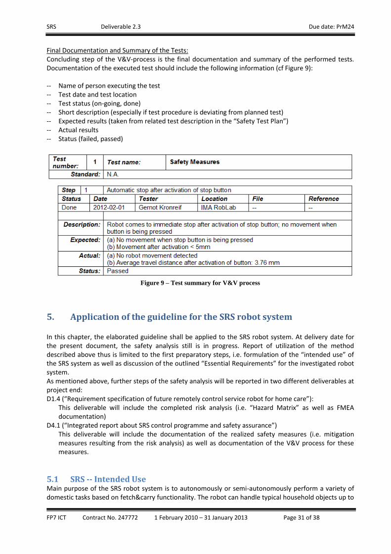
SRS Deliverable 2.3 Due date: PrM24
FP7 ICT Contract No. 247772 1 February 2010 – 31 January 2013 Page 31 of 38
Final Documentation and Summary of the Tests: Concluding step of the V&V-process is the final documentation and summary of the performed tests. Documentation of the executed test should include the following information (cf Figure 9): -- Name of person executing the test -- Test date and test location -- Test status (on-going, done) -- Short description (especially if test procedure is deviating from planned test) -- Expected results (taken from related test description in the “Safety Test Plan”) -- Actual results -- Status (failed, passed)
Figure 9 – Test summary for V&V process
5. Application of the guideline for the SRS robot system In this chapter, the elaborated guideline shall be applied to the SRS robot system. At delivery date for the present document, the safety analysis still is in progress. Report of utilization of the method described above thus is limited to the first preparatory steps, i.e. formulation of the “intended use” of the SRS system as well as discussion of the outlined “Essential Requirements” for the investigated robot system. As mentioned above, further steps of the safety analysis will be reported in two different deliverables at project end: D1.4 (“Requirement specification of future remotely control service robot for home care”):
This deliverable will include the completed risk analysis (i.e. “Hazard Matrix” as well as FMEA documentation)
D4.1 (“Integrated report about SRS control programme and safety assurance”) This deliverable will include the documentation of the realized safety measures (i.e. mitigation measures resulting from the risk analysis) as well as documentation of the V&V process for these measures.
5.1 SRS -- Intended Use Main purpose of the SRS robot system is to autonomously or semi-autonomously perform a variety of domestic tasks based on fetch&carry functionality. The robot can handle typical household objects up to

SRS Deliverable 2.3 Due date: PrM24
FP7 ICT Contract No. 247772 1 February 2010 – 31 January 2013 Page 32 of 38
a mass of 1.5 kg – the working area for such handling tasks is from floor level up to a grasping height of 1.7m. The robot itself consists of three main components: a mobile robot platform positions the SRS robot to the particular working place. An on-board manipulator arm is responsible for object manipulation. A foldable tray system finally forms the “interface” between robot and user – i.e. objects are placed on the tray in order to hand over/take over to/from the user. There is no direct physical contact between robot and user foreseen. Foreseeable misuse includes using the robot as a stand-up and/or walking assistant. Another possible misuse is to put too much payload to the robot manipulator and/or to the handling tray. From user perspective the main role is to assist the local user for fetch&carry tasks – i.e. the robot transports selected objects from defined places to defined places. No (further) compensation of any user impairment will be offered by the SRS robot system. There are different user groups to be considered for SRS. The main user is the “local user”, i.e. the person receiving support from the SRS system. This “local user” has to be considered as inexperienced, untrained and probably mentally, cognitive and/or physically impaired. The second user group is the one of “private remote operators”, i.e. the group of users who is resolving simple exceptional situations by means of a dedicated remote-control user interface. Also this user group must be considered as inexperienced or less experienced as well as untrained. Finally, the third user group is the group of “professional remote operators”. This group is able to resolve even complex exceptional situations via a dedicated high-fidelity user interface. Different to the other two user groups, the group of “professional remote operators” can be considered as well-trained and experienced. For the two remote-operator groups it needs to be considered, that operation of the robot needs to be performed under (very) limited view. Information about the working environment and about the current use situation is very much depending on sensor information, transferred via a wireless communication network with unknown communication delay and possible communication breakdown. Even if the two user groups “local user” and “private remote operator” should be considered as untrained (see definition above), an introduction of basic working principles and basic safety aspects for both user types during deployment of the SRS system is highly recommended. Foreseen environmental conditions are the ones of a typical domestic environment, i.e. generally even floor, small steps to be taken by the mobile platform (allowed step-size up to 10mm), bigger steps to be avoided, standard width for doorways (80cm and more), different floor types (wooden floor, carpet, etc). A rather unstructured environment as well as limited space for driving manoeuvres has to be considered. Other possible hazards can include: pets, other robots, frequent changes of the environment (e.g. replacement of furniture), etc. As the robot is aimed to serve foodstuff, possibility of liquid spilling over the robot is reasonable high. Negative side effects of the robot regarding its environment needs to be considered, e.g. use of ultra-sound sensors and effect to pets, unintended modification of the environment due to robot manoeuvres, etc. Installation and repair of the SRS robot system is done by trained service stuff only. During installation, the service person also checks the use environment for particular security problems (e.g. steps, loose carpets, other “no-go” areas, etc), updates the robot map, trains objects to be handled by the robot, as well as trains the local user about basic working and safety aspects (see above). Regular maintenance of the SRS system (e.g. annual robot service, e.g. recalibration of sensor systems, etc) should be considered. Functions for self-diagnosis, self-calibration – or remote diagnosis and calibration – of system components could be additional aspects for the SRS service concept.

SRS Deliverable 2.3 Due date: PrM24
FP7 ICT Contract No. 247772 1 February 2010 – 31 January 2013 Page 33 of 38
5.2 SRS -- Essential Requirements (1) BASIC REQUIREMENTS: (1.1) Intended Use / Foreseeable Misuse: The most foreseeable misuse of SRS is to use the robot system as a stand-up and/or walking aid. Care must be taken, that the design of the robot as well as of its components are not triggering such a misuse – e.g. component design should not look like handles, etc. Appropriate selection of the static payload of the most exposed components – i.e. folding tray and manipulator – must be analysed in the risk analysis. If these components change their configuration after application of certain force and in sudden manner, this might add additional risk of falling. The maximum tilting force of the robot needs to be calculated and – if possible – set to a value which prevents the robot from tilting after the user leaning on the robot. (1.2) Application of Safety Principles: Design of the robot is being accompanied with a detailed risk analysis. If critical risks are being identified, appropriate mitigation measures will be designed, implemented and verified. Extensive validation of the SRS robot will take place under real use conditions in realistic environment. Usability studies for all three user interfaces – i.e. UI_LOC, UI_PRI, and UI_PRO – are being part of the development process. The foreseen local users are only persons without impairment or with only small mental, cognitive and/or physical impairment. (1.3) Performance: Validation of the system regarding general requirements and specifications is part of the development process. (1.4) Materials Used: The robot housing has a flat surface which can be cleaned easily. Flammability and any toxic behaviour of the used materials must be investigated in detail. (1.5) Ingress of Substances: The robot basically has a flat and closed cover which should give enough protection against spilled fluids. More detailed tests regarding ingress of liquids, however, need to be executed. The most probable place for spilling of fluid is the foldable tray. Additional design elements, like a surrounding border, can further reduce the risk. Additional care must be taken in order to prevent from folding the table in case of spilled fluid. (1.6) Power Supply: A dedicated power monitor will be designed and integrated to the robots safety circuit. As soon as battery level is below a certain threshold, an automatic emergency stop is being issued -- user information will be provided accordingly. After a complete loss of power – or after any detected failure causing an emergency stop situation – continuation of operation only is possible after explicit acknowledgment of the error signal. Behaviour of moving robot components – i.e. of mobile platform, manipulator, foldable tray – after emergency stop situation and/or after loss of power needs to be investigated at the SRS risk analysis (e.g. automatic brake, manual release of brakes, etc). (1.7) Design for Transport and Handling: See (1.6). Behaviour of the robot components in emergency stop situation and/or after loss of power needs to be investigated at the SRS risk analysis. Except such an emergency stop situation, no manual

SRS Deliverable 2.3 Due date: PrM24
FP7 ICT Contract No. 247772 1 February 2010 – 31 January 2013 Page 34 of 38
movement of the robot and/or its single components is foreseen. During transport of the robot system, the robot manipulator is in parking position with the single robot links fixed by additional holding elements. (1.8) Ergonomics: No extensive remote-control of the robot is foreseen in the intended use. Intervention by remote-control users only should be temporarily. For professional remote operators being responsible for several SRS installations at the same time, appropriate measures need to be foreseen (out of scope for the SRS project). (1.9) Cleaning, Cleanness during Use: See (1.4). The robot housing has a flat surface which can be cleaned easily. (2) CONTROL SYSTEMS: (2.1) Safety and Reliability of Control Systems: Safety relevant control functions must be investigated at the SRS risk analysis. Critical functions are being implemented accordingly. Software and hardware watchdogs, checksums, etc are being implemented and integrated to the SRS safety circuit. Implementation of such safety guards in hardware should be preferred over implementation in software. Opening the safety circuit by one of the aforementioned safety guards automatically issues an emergency stop. As mentioned in (1.6), continuation of operation after any detected failure causing such an emergency stop situation only is possible after explicit acknowledgment of the error signal. Particular investigation is needed about the options to issue an emergency stop. According to the current system design, there is only one “real” emergency stop button directly fixed to the robot. Especially during faulty movement of the robot platform or of the manipulator this emergency stop button might be less useful. The robot system can be brought to a stop by UI_LOC and UI_PRI. As these two interfaces are connected to the robot via wireless communication, additional efforts must be taken into consideration (e.g. communication watchdog connected to the safety circuit of the robot). It however needs to be discussed whether these two stop functions should have emergency stop functionality. Another emergency stop function is part of UI_PRO. Also here, possible problems connected to the wireless behaviour of this stop function needs to be addressed via a dedicated communication watchdog. An additional option could be to place wireless emergency stop buttons at the user site – further analysis is part of the risk analysis. (2.2) Control Devices: See (2.1) about the placement and reachability of (emergency) stop buttons. Main operation of the SRS robot is via the set of wireless user interfaces – mainly via UI_LOC. Control devices integrated to the robot mainly are limited to ON/OFF button and an emergency button. Regarding accessibility of the wireless control devices a particular analysis is part of the SRS risk analysis. It lies in the nature of mobile devices that they are not always at hand (when needed) – no critical situation must result from such a situation. One particular aspect of SRS is the transfer of control from automatic behaviour (standard mode) to different users (local user, remote operators). Such a transfer takes place in a defined procedure -- the current operational mode is visible at all user interfaces as well as on the robot itself. Only one user interface can be used to issues robot commands at the same time. If any robot movement is issued by one of the remote operators, appropriate information (acoustic and visual warning signal) is given to the local user before movement starts. Especially from remote control interface, the operator is able to detect if any person is within the working area of the robot – but only

SRS Deliverable 2.3 Due date: PrM24
FP7 ICT Contract No. 247772 1 February 2010 – 31 January 2013 Page 35 of 38
by investigation of sensor readings rather than by direct view. At the SRS risk analysis it will be investigated if the start of a robot operation – especially connected to movement – should be possible while someone is in the working area of the robot (especially regarding the “Emergency Call” use scenario). (2.3) Starting: Starting of any robot action needs a command issued by the active user interface (for details see (2.2). Continuation of operation after any stoppage, or after any detected failure causing an emergency stop situation only is possible after explicit acknowledgment of the error signal (see 1.6). (2.4) Stopping: See (2.1) about the placement and functionality of (emergency) stop buttons. As already mentioned above, availability of (emergency) stops and the resulting stopping behaviour must be investigated in detail as part of the risk analysis process. (2.5) Selection of Control or Operating Modes: As mentioned above the SRS robot can be used in different modes – i.e. automatic mode, or remote-controlled from different users. Only one command device is active at the same time – transfer of control from one user to the other needs to be confirmed by the involved users. As written in (2.2) the current operational mode is visible at all user interfaces as well as on the robot itself. (3) MECHANICAL HAZARDS: (3.1) Risk of Loss of Stability: Situations which cause an overturning of the robot are being addressed at the SRS risk analysis. One major cause is a misuse of the system – e.g. using the robot as stand-up device or walking assistant. Such a misuse needs to be prevented by both design options as well as user information. A second group of failure causes is related to erroneous global/local navigation – e.g. high accelerations, collisions between robot and environment, or commanding the robot to “no-go” areas like steps, bumpy terrain, ramps, etc. Countermeasures for such failures include (hardware) limitation of high acceleration, traversability analysis, obstacle avoidance, etc. Beside of such safety measures, an appropriate design of the robot should address the problem of tilting by increased ground support area (which on the other hand reduces manoeuvrability) as well as low center of gravity. An additional tilt sensor could measure undesired dynamics and reduces robot speed and/or acceleration. (3.2) Risk of Break-up during Operation: According to the intended use the applied external forces are rather small so that no break of components needs to be considered. The design, however, also has to consider the foreseeable misuse of using the robot system as stand-up and walking aid. Appropriate countermeasures (e.g. use of overload prevention measures) need to be defined at the risk analysis, as already pointed out in (1.1). (3.3) Risks due to Falling or Ejected Objects: The robot gripper is designed in a way that the gripper keeps closed even after loss of power. The gripping process should be form-fit rather than force-fit – whenever possible. Transfer of objects will be limited as much as possible, i.e. only between grasping position and foldable tray or the other way round. Objects should be prevented from falling during transport by adding a border around the foldable tray. In addition, limited acceleration as well as smooth trajectories (also considering floor conditions) reduces the risk of falling objects.

SRS Deliverable 2.3 Due date: PrM24
FP7 ICT Contract No. 247772 1 February 2010 – 31 January 2013 Page 36 of 38
(3.4) Risks due to Surfaces or Edges, moving (transmission) Elements: The robot’s main body is covered by a soft surface. Accessible parts of the robot have no sharp edges and no rough surfaces likely to cause injury. There are no accessible transmission elements and no critical gaps. As direct physical contact is not foreseen in the intended use, there is no need to move the robot close to a human. The procedure of folding the manipulator to its parking position, however, needs to be investigated in detail at the SRS risk analysis due to the inherent risk of crushing parts of the human body of a local user. (4) HAZARDS RELATED TO MOBILITY OF THE ROBOT: (4.1) Visibility for Manual Operation: One of the basic hazards connected to the SRS setup is the limited view (no direct view, environmental information only based on sensor information, transfer of sensor data via wireless communication with undetermined communication delays) for the remote operators. A movement of the robot close to humans thus is limited as much as possible. Movement under the given conditions only should be step-wise (at least if such a movement needs to take place in the presence of a human) – between two consecutive movement steps the environmental conditions need to be evaluated. (4.2) Remote-Controlled Operation: The transfer of robot control between the different user interfaces is already addressed above (e.g. (2.2)). As already mentioned above, movement of the robot – at least under hazardous conditions -- only is allowed in a step-wise manner with intermediate evaluation of safety conditions. Such a step-wise movement will be established despite of the kind of user input. Used control devices, however, are designed in a way that the input signal is not self-locking (e.g. joystick returning to neutral position as soon as they are released by the operator, push-button instead of switch, etc). Dedicated communication watchdogs are observing the (wireless) connection between remote user-interfaces and robot control. If the communication delay is bigger than a certain threshold, such a communication watchdog immediately causes a (emergency) stop situation by interrupting the robot’s safety circuit. (4.3) Signals and warnings: Each robot movement caused by commands issued remotely will be signalized by visual and acoustic warnings in order to inform the local user(s). (5) EMISSION: (5.1) Sound: The emitted sound of the robot under normal conditions can be neglected. Acoustic signals (e.g. warning about robot movement caused by remote control commands) are designed in accordance to related standards. The use of ultra-sound sensors for the SRS robot system is not foreseen. (5.2) Radiation: Used laser sensors are Class 1 sensors (in accordance to IEC 60825-111) and thus can be considered as eye-safe. Mounting of sensors, however, is in a way, that no direct access to laser beams takes place for
11
Safety of laser products - Part 1: Equipment classification and requirements

SRS Deliverable 2.3 Due date: PrM24
FP7 ICT Contract No. 247772 1 February 2010 – 31 January 2013 Page 37 of 38
the intended use of the robot. The used IR-based sensors are standard consumer electronic articles12 and thus no safety related aspects are expected13. (5.3) Emissions of Hazardous Materials and Substances: The robot body is being covered with a plastics/foam material. Analysis of toxic behaviour, hazard of allergic reactions, etc are on-going. Further emission of substances, like lubrication, can be neglected.
6. Summary and Outlook This chapter is summarizing the present document and describes the next steps for safety related investigations.
6.1 Summary This document is intended to serve as a general guideline for the design of a safe service robot system comparable to the SRS setup. Based on existing EC directives and standards, a step-by-step approach is being outlined, starting with the definition of the “intended use” of the analysed system and the discussion of (general) “Essential Requirements” for a safe robot system. In the next step, the combination of common hazards on the one hand and desired system functionality on the other, combined together in a “Hazard Matrix”, helps to outline a set of system-specific hazards, which then sets the basis for a later risk analysis process using FMEA method. Here, each of the system-specific hazards is being investigated for possible failure causes and for the associated risk. Part of the risk analysis process also is to identify “critical risks” in order to define mitigation measures to lower the risk. For validation and verification (“V&V-process”) of the safety measures, worksheets for setting up a test plan and documentation are being proposed in this guideline. As described above, the aforementioned process is “in progress” during finalisation of this document. The first two steps of the application of the outlined methods for the SRS project – i.e. the definition of the “intended use” as well as the discussion of the “Essential Requirements” – are documented in this deliverable. Results of the two remaining steps – i.e. risk analysis and V&V-process – will be documented in other SRS deliverables at project end.
6.2 Next steps for SRS Safety Management Main steps to be taken are the completion of the SRS risk analysis as well as verification and validation of the identified and realized mitigation measures for risk reduction. As already mentioned earlier in this document, the completed risk analysis including a finalized “Hazard Matrix” will be reported in the final version of SRS deliverable D1.4 (“Requirement specification of future remotely control service robot for home care”). The risk analysis will concentrate to the SRS functionality and components. A risk analysis of the used robot system “Care-o-Bot 3” already exists – the risk analysis performed under the present EC-funded project only references to this previous analysis.
12
Kinect, Microsoft Inc. 13
As far as known to the author, the laser itself is 780nm wavelength. Furthermore, the light is not collimated, but rather diffused so that it covers a wide area. The power of the laser ends up at less than 0.4 µW once it actually reaches the user. The used laser is rated as a Class 1 laser device, which means the maximum emitted power of the laser is <25 μW.

SRS Deliverable 2.3 Due date: PrM24
FP7 ICT Contract No. 247772 1 February 2010 – 31 January 2013 Page 38 of 38
During the aforementioned “Risk Analysis” “critical risks” are being identified and appropriate countermeasures will be proposed. In the framework of the EC selected measures will be designed in more detail and implemented. Regarding the current state of the risk analysis such measures include: -- safety system including power sensing and communication watchdog -- wireless emergency stop connected to safety system -- human sensing, i.e. detection of the presence and the location of local user(s) in the working area of
the robot system -- collision avoidance for the manipulator arm -- safety related improvements of the foldable tray -- safety related elements regarding change of operation modes and transfer of control As already mentioned earlier in this document, the implementation of these safety measures and their validation and verification according to the method defined in this document will be reported in the final version of SRS deliverable D4.1 (“Integrated report about SRS control programme and safety assurance”).