methodology for plant system i&c specifications - …static.iter.org/codac/pcdh7/folder...
TRANSCRIPT
PDF generated on 24-Mar-2013DISCLAIMER : UNCONTROLLED WHEN PRINTED – PLEASE CHECK THE STATUS OF THE DOCUMENT IN IDM
How To
Methodology for Plant System I&C specifications
This document completes the PCDH core document by focusing on methodology for plant system I&C technical specifications. It aims to give guidelines to issue the deliverables for the design phase as mentioned in PCDH, scope and workflow for I&C design data
Approval Process Name Action AffiliationAuthor Journeaux J.- Y. 12-Mar-2013:signed IO/DG/DIP/CHD/CSD/PCICoAuthorReviewers Wallander A.
Yonekawa I. 24-Mar-2013:recommended20-Mar-2013:recommended
IO/DG/DIP/CHD/CSDIO/DG/DIP/CHD/CSD/PCI
Approver Thomas P. 24-Mar-2013:approved IO/DG/DIP/CHDDocument Security: level 1 (IO unclassified)
RO: Journeaux Jean-YvesRead Access AD: ITER, AD: External Collaborators, AD: Division - Control System Division - EXT, AD: Section -
CODAC - EXT, AD: Section - CODAC, project administrator, RO, LG: CODAC team
IDM UID
353AZYVERSION CREATED ON / VERSION / STATUS
12 Mar 2013 / 6.2/ Approved
EXTERNAL REFERENCE

PDF generated on 24-Mar-2013DISCLAIMER : UNCONTROLLED WHEN PRINTED – PLEASE CHECK THE STATUS OF THE DOCUMENT IN IDM
Change Log
Title (Uid) Version
Latest Status Issue Date Description of Change
Methodology for Plant System I&C specifications (353AZY_v6_2)
v6.2 Approved 12 Mar 2013
Version updated for HW data workflow
Methodology for Plant System I&C specifications (353AZY_v6_1)
v6.1 Signed 26 Feb 2013
Controller chassis removed from PSP data scope after Denis/Manoj review
Methodology for Plant System I&C specifications (353AZY_v6_0)
v6.0 Signed 21 Feb 2013
Version to be published in scope of PCDH v7
Methodology for Plant System I&C specifications (353AZY_v5_6)
v5.6 Signed 21 Feb 2013
Version ready to b publieshed in scope of PCDH v7
Methodology for Plant System I&C specifications (353AZY_v5_5)
v5.5 Signed 21 Feb 2013
Version ready to be published in scope of PCDH v7
Methodology for Plant System I&C specifications (353AZY_v5_4)
v5.4 Signed 21 Feb 2013
Version ready to be published in scope of PCDH v7
Methodology for Plant System I&C specifications (353AZY_v5_3)
v5.3 Signed 21 Feb 2013
Version ready to be published in scope of PCDH v7
Methodology for Plant System I&C specifications (353AZY_v5_2)
v5.2 Signed 21 Feb 2013
Version ready to be published in scope of PCDH v7
Methodology for Plant System I&C specifications (353AZY_v5_1)
v5.1 Signed 21 Feb 2013
Small changes from Denis comments ibn figure 7. Version ready to be published in scope of PCDH v7
Methodology for Plant System I&C specifications (353AZY_v5_0)
v5.0 Signed 21 Feb 2013
New version which clarfifies the work flow for PCDH deliverables for I&C specc and PSP data
Methodology for Plant System I&C specifications (353AZY_v4_1)
v4.1 Signed 06 Feb 2013
Same as 4.0 but with all changes accepted
PDF generated on 24-Mar-2013DISCLAIMER : UNCONTROLLED WHEN PRINTED – PLEASE CHECK THE STATUS OF THE DOCUMENT IN IDM
Methodology for Plant System I&C specifications (353AZY_v4_0)
v4.0 Signed 04 Feb 2013
Update in scope of PCDH v7. Workflow and scope of I&C design data clarified
Methodology for Plant System I&C specifications (353AZY_v3_3)
v3.3 Approved 08 Feb 2011
Update after PCDH v6 external review
Methodology for Plant System I&C specifications (353AZY_v3_2)
v3.2 Signed 05 Jan 2011
John Poole review, version for PCDH v6 external review
Methodology for Plant System I&C specifications (353AZY_v3_1)
v3.1 Signed 03 Jan 2011
New version to be reviewed in scope of PCDH v6.
if(typeof editorarray == 'object')
{
editorarray.push('ctl00_MasterPlaceHolder_DocumentView1_ctl01_ctl00_ctl00_ctl16_ver_description')
}
Methodology for Plant System I&C specifications (353AZY_v3_0)
v3.0 Signed 03 Jan 2011
New version to be reviewed in scope of PCDH v6.
Methodology for Plant System I&C specifications (353AZY_v2_0)
v2.0 Approved 28 Jan 2010
PCDH v5 review included
Methodology for Plant System I&C specifications (353AZY_v1_3)
v1.3 Signed 26 Jan 2010
Update after official review for PCDH v5
Methodology for Plant System I&C specifications (353AZY_v1_2)
v1.2 Signed 10 Dec 2009
Review of PCDH docs references
Methodology for Plant System I&C specifications (353AZY_v1_1)
v1.1 Signed 10 Dec 2009
IDM ref updated
Methodology for Plant System I&C specifications (353AZY_v1_0)
v1.0 In Work 10 Dec 2009

PDF generated on 24-Mar-2013DISCLAIMER : UNCONTROLLED WHEN PRINTED – PLEASE CHECK THE STATUS OF THE DOCUMENT IN IDM

Document revision history
Revision Date Description Modified Pages 0 04/09/2009 First draft for PCDH v51 10/09/2009 First CODAC review comments included 2 to 9
2.1 21/09/2009 Second CODAC review comments included 2 to 142.2 30/10/2009 IO review comments included 2 to 142.3 25/01/2010 J Poole and IO review 2 to 143.0 15/11/2010 New version for PCDH v6, maturity tables and FBS
added. Other sections simplified, no change on inputs and deliverable lists and definition.
2 to 4
3.1 17/12/2010 Intermediate version3.2 05/01/2011 J Poole review All pages3.3 08/02/2011 Final version for PCDH v6.1 Cover page
Draft for PCDH v7List of reference document reviewed: introduction of “Iter system design process (SDP) working instruction”
64.0 07/08/2012
Clean-up of PCDH deliverable list to stick on “Iter system design process (SDP) working instruction”
8-9-10
5.0 24/01/2013 Version published in scope of PCDH v7. Clarification of scope and workflow for PSP data
Chapter 3 introduced
5.1 04/02/2013 Version reviewed by Denis for PSP data scope5.2 20/02/13 Version including details for work-flows 8 to 135.3 26/02/2013 Controller chassis cancelled from PSP data scope

TABLE of CONTENTS
1. INTRODUCTION..........................................................................................................................3
1.1. PCDH context .......................................................................................................................3
1.2. Document scope ....................................................................................................................3
1.3. Document identifiers ............................................................................................................4
1.4. Acronyms ..............................................................................................................................4
1.5. Reference documents ...........................................................................................................5
2. TECHNICAL SPECIFICATIONS of PLANT SYSTEM I&C ....................................................6
2.1. Scope of the technical specifications for I&C systems ......................................................6
2.2. Life-cycle for I&C systems ..................................................................................................6
2.3. Technical specifications for I&C systems: required inputs .............................................7
2.4. Technical specifications for I&C systems: PCDH deliverables required at completion of the design phase.............................................................................................................................7
2.5. Review of PCDH deliverables for I&C technical specifications. .....................................9
2.6. PCDH deliverables work flow for the I&C technical specifications ...............................9
2.7. Workflow for D1Bs ...........................................................................................................10
2.8. Workflow for D1Cs ............................................................................................................11
2.9. Workflow for D5.................................................................................................................12
2.10. Workflow for D6.................................................................................................................12
2.11. Workflow for D7.................................................................................................................12
2.12. Workflow for D8.................................................................................................................12
2.13. Workflow for D9.................................................................................................................13
3. I&C DESIGN DATA ...................................................................................................................14
3.1. I&C design data scope .......................................................................................................14
3.2. Model in use for PSP data (HW only): .............................................................................15
4. I&C DESIGN DATA WORK FLOW ..........................................................................................16
4.1. Work flow over view for I&C design data.......................................................................16
4.2. Work flow for PS I&C physical architecture and related PSP data:............................16

1. INTRODUCTION
1.1.PCDH contextThe Plant Control Design Handbook (PCDH) [RD1] defines methodology, standards, specifications and interfaces applicable to ITER Plant Systems Instrumentation & Control (I&C) System life cycle. I&C standards are essential for ITER to:
• Integrate all plant systems into one integrated control system.• Maintain all plant systems after delivery acceptance.• Contain cost by economy of scale.
PCDH comprises a core document which presents the plant system I&C life cycle and recaps the main rules to be applied to the plant system I&Cs for conventional controls, interlocks and safety controls. Some I&C topics are explained in greater detail in dedicated documents associated with PCDH as presented in Figure 1-1.
This document is one of them.
Core PCDH (27LH2V)Plant system control philosophyPlant system control Life CyclePlant system control specificationsCODAC interface specificationsInterlock I&C specificationSafety I&C specification
PCDH core and satellite documents: v7PS CONTROL DESIGN
Plant system I&C architecture (32GEBH)
Methodology for PS I&C specifications (353AZY)
CODAC Core System Overview (34SDZ5) INTERLOCK CONTROLS
Guidelines PIS design (3PZ2D2)
Guidelines for PIS integration & config.Management of local interlock functionsPIS Operation and Maintenance
I&C CONVENTIONSI&C Signal and variable naming (2UT8SH)
ITER CODAC Glossary (34QECT)
ITER CODAC Acronym list (2LT73V)
PS SELF DESCRIPTION DATASelf description schema documentation (34QXCP)
CATALOGUES for PS CONTROLSlow controllers products (333J33)
Fast controller products (345X28)
Cubicle products (35LXVZ)
Integration kit for PS I&C
PS CONTROL INTEGRATIONThe CODAC -PS Interface (34V362)
PS I&C integration plan (3VVU9W)
ITER alarm system management (3WCD7T)
ITER operator user interface (3XLESZ)
Guidelines for PON archivingPS Operating State management (AC2P4J)
Guidelines for Diagnostic data structure (354SJ3)PS CONTROL DEVELOPMENT
I&C signal interface (3299VT)
PLC software engineering handbook (3QPL4H)
Guidelines for fast controllers (333K4C)
CODAC software development environment (2NRS2K)
Guidelines for I&C cubicle configurations (4H5DW6)
CWS case study specifications (35W299)
NUCLEAR PCDH (2YNEFU)
OCCUPATIONAL SAFETY CONTROLSGuidelines for PSS design
Available and approvedExpected
Legend
This document
(XXXXXX) IDM ref.
Methodology for PS I&C specifications (353AZY)
Figure 1-1: PCDH documents structure
1.2. Document scopeThis document completes the PCDH core document by focusing on deliverables and workflows applicable to plant system I&C design. The document scope is the plant system I&C technical specifications for conventional, interlock and occupational safety controls; this document does not address the N-Safety controls.

1.3.Document identifiersTable 1 provides the full list of identifiers used in this document. The recommendations raised in this document as for the other PCDH satellite documents are mainly guidelines; some are rules and in such a case they are identified by a star symbol.
Table 1: Paragraph identifiers
AD Applicable DocumentGL Glossary itemRD Reference Document Rules referenced in core PCDH
1.4.AcronymsTable 2 shows the acronyms used in this document. The relevant acronyms have been extracted from the complete list in PCDH.
Acronym ItemCAD Computer-Aided DesignCBS Control Breakdown StructureCODAC COntrol, Data Access and CommunicationCOS Common Operating StateDO Design OfficeFAT Factory Acceptance TestsHMI Human Machine InterfaceI&C Instrumentation & ControlIO ITER OrganizationI/O Inputs and OutputsIS Interface SheetHW HardwarePA Procurement ArrangementPCDH Plant Control Design HandbookPFD Process Flow DiagramsP&ID Process and Instrumentation DiagramPSOS Plant System Operating StatePSP Plant System Profile databasePV Process Variable RAMI Reliability, Availability, Maintainability and InspectabilityRO Responsible OfficerSAT Site Acceptance TestsSDD Self Description DataSRD System Requirement DocumentTBC To Be ConfirmedTBD To Be Defined
Table 2: Abbreviations and acronyms
1.5. Reference documents[RD1] Plant Control Design Handbook (27LH2V) [RD2] Design review procedure (2832CF)[RD3] ITER system design process (sdp) working instruction (4CK4MT)[RD4] ITER Control Breakdown Structure (CBS) (9TYFWC)[RD5] Function Analysis Diagram Tool Specification (3NSG6U) [RD6] CWS case study specifications (35W299) [RD7] Plant System I&C Architecture (32GEBH)[RD8] Template for I&C configuration design data (3NTEU3) [RD9] I&C cubicle internal configuration (4H5DW6)[RD10] Guidelines for PSOS SM management by COS SM (AC2P4J) [RD11] Plant system I&C Integration plan (3VVU9W)[RD12] Integration Kit for PS I&C (C8X9AE)[RD13] I&C signal and process variable naming convention (2UT8SH)[RD14] I&C signal interface (3299VT)
2. TECHNICAL SPECIFICATIONS of PLANT SYSTEM I&C
2.1. Scope of the technical specifications for I&C systemsAs a general statement, the technical specifications for plant system I&C are made of following topics:
1. Functional specifications for identifying the controls required to get a suitable and safe plant system operation. This part is driven by the plant system process and by the plant system operation requirements.
2. Interface specifications with other systems.3. Design requirements as mandatory requirements targeting the manufacture. The target is to
select technologies and architectures as standards for integration purpose. These requirements applicable to ITER I&C systems have been pushed into the PCDH.
4. Guidelines which are also targeting the manufacture are recommendations for detailing how to implement the PCDH standards. For ITER I&C systems these guidelines can be consulted in the PCDH satellite documents, see the PCDH package on Figure 1-1.
Points 3 and 4 are specified into the PCDH. This document targets the definition of content for the points 1 and 2 and work-flow for working out.
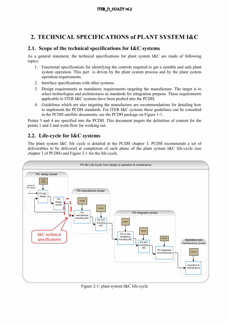
2.2. Life-cycle for I&C systemsThe plant system I&C life cycle is detailed in the PCDH chapter 3. PCDH recommends a set of deliverables to be delivered at completion of each phase of the plant system I&C life-cycle (see chapter 3 of PCDH) and Figure 2-1 for the life-cycle.
EDHPCDH
PS I&C Life Cycle: from design to operation & maintenance
PS I&C design
PS design review
PS design phase
PS manufacture including I&C
PCDH
PS manufacture phase
PS FAT including
I&C
PCDH
PS on site Installation
including I&C
PCDH
PS integrated commissioning
PS integration phase
PS SAT including
I&C
PCDH
PCDH
Operation and maintenance phase
Operation & maintenance
PCDH
Inputs for I&C design
Figure 2-1: plant system I&C life-cycle
I&C technical specifications

2.3. Technical specifications for I&C systems: required inputs A set of inputs are assumed to be available to initiate the I&C design. These inputs shall be provided by the plant system RO at the conceptual design stage. They are listed as follows:
Input ID
Scope
[I1] I1 is the plant system I&C operation and control philosophy for specifying how the plant system is expected to be operated: Scenarios, who will be involved in the operation, level of automation (fully automatic, semi, or manual), what are the services expected from other systems, the services provided to other systems and the environmental constraints.
[I2] I2 is the plant system functional analysis. This functional analysis is control system oriented. I2 is the main input for determining the Control Breakdown Structure (CBS) that will be the base for naming the control function and I&C data.
[I3] I3 are all plant system PFDs, mechanical and electrical drawings and diagrams needed at the design phase. These drawings are required to support the detailed functional specifications.
[I4] I4 is a list and short description of the plant system operating states. [I5] I5 is the plant system risk analysis for determining the risks to protect the plant system.[I6] I6 is the system Interface Control Documents (S-ICDs) relevant for the plant system I&C.[I7] I7 is the list and specifications of the main protection functions to implement in the plant
system I&C. ITER interlock controls are identified from this list.[I8] I8 is the list and specifications of the main safety functions to implement within the plant
system or with respect to other plant systems. Safety controls are identified from this list.
2.4. Technical specifications for I&C systems: PCDH deliverables required at completion of the design phase
In scope of the ITER design reviews, a set of documents are specified in the PCDH to be delivered an reviewed. These documents target the functional and physical interfaces with central I&C systems. These documents are listed below:
D1 Plant system I&C architecture. D5 Plant system controller(s) performance and configuration requirements. D6 List of inputs and outputs (I/O) of the I&C controllers. D7 List of data at Central I&C functional interface. D8 Configuration of I&C cubicles. D9 Specifications of plant system operating state machines.
These deliverables are assumed to be reviewed in the Design Reviews of the PA or Plant Systems and are mentioned in the ITER system design process working instruction [RD3].
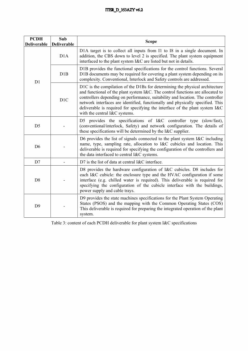
The Table 3 provides further details about the content of each deliverable.
PCDH Deliverable
Sub Deliverable Scope
D1AD1A target is to collect all inputs from I1 to I8 in a single document. In addition, the CBS down to level 2 is specified. The plant system equipment interfaced to the plant system I&C are listed but not in details.
D1BD1B provides the functional specifications for the control functions. Several D1B documents may be required for covering a plant system depending on its complexity. Conventional, Interlock and Safety controls are addressed.D1
D1C
D1C is the compilation of the D1Bs for determining the physical architecture and functional of the plant system I&C. The control functions are allocated to controllers depending on performance, suitability and location. The controller network interfaces are identified, functionally and physically specified. This deliverable is required for specifying the interface of the plant system I&C with the central I&C systems.
D5 -D5 provides the specifications of I&C controller type (slow/fast), (conventional/interlock, Safety) and network configuration. The details of these specifications will be determined by the I&C supplier.
D6 -
D6 provides the list of signals connected to the plant system I&C including name, type, sampling rate, allocation to I&C cubicles and location. This deliverable is required for specifying the configuration of the controllers and the data interfaced to central I&C systems.
D7 - D7 is the list of data at central I&C interface.
D8 -
D8 provides the hardware configuration of I&C cubicles. D8 includes for each I&C cubicle: the enclosure type and the HVAC configuration if some interface (e.g. chilled water is required). This deliverable is required for specifying the configuration of the cubicle interface with the buildings, power supply and cable trays.
D9 -
D9 provides the state machines specifications for the Plant System Operating States (PSOS) and the mapping with the Common Operating States (COS) This deliverable is required for preparing the integrated operation of the plant system.
Table 3: content of each PCDH deliverable for plant system I&C specifications

2.5. Review of PCDH deliverables for I&C technical specifications.
Table 4 provides the maturity level of each deliverable required for each of the design reviews, Conceptual Design Review (CDR), Preliminary Design Review (PDR) and Final Design Review (FDR). The level of maturity of the draft version will depend on the maturity level of the plant system design.
PCDH ID Document availability and review status for reviews
Dx Name CDR PDR FDRD1 Plant system I&C
architecture.Not
Required Draft version Fully consolidated version
D5 Plant system controller(s) configuration requirements.
Not Required Draft version Fully consolidated
version
D6 List of signals Not Required Draft version Fully consolidated
version
D7 List of the data interfaced to Central I&C systems
Not Required Draft version Fully consolidated
version
D8 Configuration of I&C cubicles.
Not Required Draft version Fully consolidated
version
D9 Description of plant system state machines.
Not Required Draft version Fully consolidated
version
Table 4: maturity levels depending on design reviews for I&C specifications
2.6. PCDH deliverables work flow for the I&C technical specifications
The Figure 2 provides an overview of the work flow for the PCDH deliverables for the I&C technical specifications.
Technical requirements
Operation Requirements
Safety & protectionrequirements
Integration requirements
Functional analysis: D1A,
and D1B
Conceptual architecture;
D1C
Controller configuration:
D5
Cubicle configuration:
D8
Signal listD6
CODAC data interface D7
CODAC functional
interface D9DESIGN PHASE
Design inputs I1 to I8
Figure 2: Overview of the work flow for the PCDH deliverables

To issue these PCDH deliverables, following steps are processed:1. The inputs I1 to I8 are collected together and pushed into the D1A. D1A introduces the CBS
level 2 for identifying the plant system I&C to implement. D1A has a free format, the content is text explanation supported by drawings. The scope is identical to I1 to I8 plus the CBS level 2.
2. A preliminary list of signals (D6) is issued from various design documents including drawings like PFDs and P&IDs.
3. D1Bs are issued from D1A and any other relevant document. The list of signals D6 is updated whenever additional signals are introduced for performing the control functions. The CBS level 3 and 4 are defined at that step.
4. D1C is issued for specifying the complete control system architecture of the plant system for physical and functional architecture both. The plant system Interface Sheets (IS) are updated accordingly.
5. D5 is issued from D1C for specifying the controller type and technology for each I&C controllers. D5 can be merged with D1C for simplification.
6. D7 is an output of D1C for defining the list of data to be interfaced to central I&C.7. D8 for specifying the I&C cubicles is issued using D6 and D1C as inputs.8. D9 is can be processed independently from other PCDH deliverables. D9 is made of the I4
and introduces in addition the COS/PSOS mapping table.
2.7. Workflow for D1Bs
The Figure 4 provides an illustration of D1B document. The document is structured into two sections:
The first section is addressing a process description in words and illustrated with diagrams/drawings by the Design Office databases and relevant CAD tools.
The second section is the description in words of the control function to implement for controlling the process as specified in the first section. This description is illustrated by control function diagrams provided by the Design Office databases and the dedicated CAD tool. In addition some tables are introduced to specify the data links introduced by the control function diagrams.See [RD5] for details about the specifications of the dedicated tool for the control functions diagrams. See PCDH [RD6] as an illustration of PCDH deliverables.
Figure 4: illustration of D1B from [RD6]

Figure 6: illustration of physical and functional architectures for control systems
Assumed the repository for D1B documents is currently IDM (future EDB), the repository for drawings is the Design Office databases and the repository for I&C design data is the Plant System Profile database (PSP), the following workflow is expected for D1B documents:
1. Starting point: The plant system drawings required for working out the D1B are made available in DO databases with appropriate level of maturity and details. The I&C components and signals addressed by the D1Bs are identified and named into the DO databases. The CBS down to the level 2 is made available in PSP.
2. The plant system I&C components and signals name and locations are pushed to the PSP from DO databases.
3. The D1Bs are worked out using MS office tools and drawings from DO CAD tools. The D1B files are stored in IDM/EDB and are reviewed as IDM/EDB materials.
4. The relevant PSP data introduced by the D1Bs for Process Variables and CBS below the level 2 are pushed to the PSP database.
5. The DO database is kept updated with the CBS from PSP for being able to name the control functions and with signals if some additional signals have been introduced.
Figure 4: Work flow between DO database, IDM/EDB repositories and PSP database.
2.8. Workflow for D1Cs
D1C document shall specify the functional and physical architectures of the plant system control systems. Where several plant system I&C and several PAs are involved in, the relevant boundaries shall be specified for clarification purpose of the physical and functional interfaces. The D1Cs are worked out using MS office tools and drawings from MS Visio tools for I&C architectures. The D1C files are stored in IDM/EDB and are reviewed as IDM/EDB materials.The PCDH document [RD7] provides the relevant guidelines for defining the physical and functional architectures; see such illustrations on Figure 6.The PSP data output from D1C are the identification of the control units (PSH, fast controller, slow controller) involved in the plant system I&Cs and the definition of interfaces with Central I&C systems and PAs. The PSP database and the Interface Sheets (IS) are updated accordingly.
PSP
DO
IDM/EDB
Component listSignal list
Drawings
CBS
PSP data

2.9. Workflow for D5
D5 addresses the configuration of the I&C controllers (fast and slow) for all controllers identified in the D1C document. D5 purpose is to provide additional information regarding the HW configuration for:
Selection of control type out of conventional, interlock, Safety. SIL level if relevant: check the PIS and PSS PCDH guidelines for that purpose. Technology: Check the PCDH catalogues for that purpose.
D5 is a document worked out using MS office tools. The D5 files are stored in IDM/EDB and are reviewed as IDM/EDB materials.The PSP database is updated accordingly.
2.10.Workflow for D6
D6 addresses the list of signals. As assumed DO database is the central repository for signals D6 is extracted from DO database. At the time this document is issued, this assumption is not met yet. D6 can be temporary supported by Excel files as specified in [RD8] template for the signal sheet.D6 is used to keep the PSP database updated with signals.
2.11.Workflow for D7
D7 addresses the list of data at Central I&C interface. For the design phase, it is assumed this list is limited to data reflecting signals and other data introduced by the D1B documents in scope of the specifications of the control functions. Therefore, D7 is not the final one list of plant system data. It is assumed the final list will be issued from SDD database and associated tools. See chapter 4 for further details.The repository for D7 data is the PSP database. D7 is supported by Excel sheets as specified in [RD8] template for data import into the PSP database.The Central I&C Interface Sheets are updated accordingly.
2.12.Workflow for D8
D8 addresses the cubicle configuration for defining, the cubicle name, type, location, Central I&C physical interface, power supply interface, cooling if required and internal configuration.The document [RD9] for cubicle internal configuration is used as a guideline for that scope.D8 is a document worked out using MS office tools. The D8 files are stored in IDM/EDB and are reviewed as IDM/EDB materialsSome PSP data are exported from D8 to PSP using Excel sheets as specified in the [RD8] template.

2.13.Workflow for D9
D9 addresses the plant system operating states (PSOS) and associated state machine. In addition D9 provide the mapping between PSOS and COS.The PCDH document [RD6] as an illustration of PCDH deliverables and illustration of PSOS definition and state machines.The PCDH document [RD10] for PSOS management is used as a guideline for the mapping of the PSOS with the COS.D9 is a document worked out using MS office tools. The D9 files are stored in IDM/EDB and are reviewed as IDM/EDB materialsSome PSP data are exported from D9 to PSP using Excel sheets as specified in the [RD8] template.
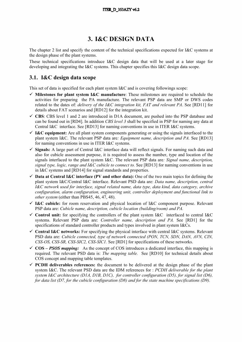
3. I&C DESIGN DATAThe chapter 2 list and specify the content of the technical specifications expected for I&C systems at the design phase of the plant systems.These technical specifications introduce I&C design data that will be used at a later stage for developing and integrating the I&C systems. This chapter specifies this I&C design data scope.
3.1. I&C design data scope
This set of data is specified for each plant system I&C and is covering followings scope: Milestones for plant system I&C manufacture: These milestones are required to schedule the
activities for preparing the PA manufacture. The relevant PSP data are SMP or DWS codes related to the dates of: delivery of the I&C integration kit, FAT and relevant PA. See [RD11] for details about FAT scenarios and [RD12] for the integration kit.
CBS: CBS level 1 and 2 are introduced in D1A document, are pushed into the PSP database and can be found out in [RD4]. In addition CBS level 3 shall be specified in PSP for naming any data at Central I&C interface. See [RD13] for naming conventions in use in ITER I&C systems.
I&C equipment: Are all plant system components generating or using the signals interfaced to the plant system I&C. The relevant PSP data are: Equipment name, description and PA. See [RD13] for naming conventions in use in ITER I&C systems.
Signals: A large part of Central I&C interface data will reflect signals. For naming such data and also for cubicle assessment purpose, it is required to assess the number, type and location of the signals interfaced to the plant system I&C. The relevant PSP data are: Signal name, description, signal type, logic, range and I&C cubicle to connect to. See [RD13] for naming conventions in use in I&C systems and [RD14] for signal standards and properties.
Data at Central I&C interface (PV and other data): One of the two main topics for defining the plant system I&C/Central I&C interface. Relevant PSD data are: Data name, description, central I&C network used for interface, signal related name, data type, data kind, data category, archive configuration, alarm configuration, engineering unit, controller deployment and functional link to other system (either than PBS45, 46, 47, 48).
I&C cubicle: for room reservation and physical location of I&C component purpose. Relevant PSP data are: Cubicle name, description, cubicle location (building/room) and PA.
Control unit: for specifying the controllers of the plant system I&C interfaced to central I&C systems. Relevant PSP data are: Controller name, description and PA. See [RD1] for the specifications of standard controller products and types involved in plant system I&Cs.
Central I&C networks: For specifying the physical interface with central I&C systems. Relevant PSD data are: Cubicle connected, type of network connected (PON, TCN, SDN, DAN, AVN, CIN, CSS-OS, CSS-SR, CSS-SIC2, CSS-SIC1. See [RD1] for specifications of these networks.
COS – PSOS mapping: As the concept of COS introduces a dedicated interface, this mapping is required. The relevant PSD data is: The mapping table. See [RD10] for technical details about COS concept and mapping table templates.
PCDH deliverables references: the document to be delivered at the design phase of the plant system I&C. The relevant PSD data are the IDM references for : PCDH deliverable for the plant system I&C architecture (D1A, D1B, D1C), for controller configuration (D5), for signal list (D6), for data list (D7, for the cubicle configuration (D8) and for the state machine specifications (D9).

3.2. Model in use for PSP data (HW only):
Controllers A controller is identified by its CPU name. A controller is assigned to one and only one cubicle. Several controllers of same PS I&C can share the same cubicle.
Cubicles: A PS I&C is made of integer number of cubicles (no cubicle sharing / PS I&C) A cubicle is delivered by one and only one PA (no cubicle sharing / PA)
Signals: The PS I&C signals are connected to cubicles.
Networks: The PS I&C network interfaces with central I&C are identified at cubicle level.
34XXXX-PLC-NNNN34XXXX-CU-NNNN
RIO34XXXX-CU-NNNN
RIO34XXXX-CU-NNNN
Netw
ork
Netw
ork
Signals
Signals
Signals

4. I&C DESIGN DATA WORK FLOWThe chapter 3 specifies the scope of I&C design data, this chapter specifies the expected work flow and tools for defining the data and populating the Plant System Profile (PSP) database.
4.1. Work flow over view for I&C design data
Considering the PSP data scope introduced in the previous section of this document, the suitable work flow for pushing this data from input sources up to SW engineering tool is illustrated in the Figure 7. The details for the scope considered in section 3.1 are given in the section 2.5 of that document. The work flow between PSP and SDD database is not in the scope of this document.
PCDH deliverables D1A for CBS2 D1B for CBS3 and funct. specs D1C for architecture and network interfaces D5 for controls unit configurations D6 for signals list D7 for data list D8 for cubicles configurations D9 for plant system state machines
PS I&C SW engineering
toolsPSP SDD
Excel sheet for I&C design data collection
Reports Plant system IS in EDB Cubicle configuration Controller configuration Other TBD
DO DB
PSP data
I&C project development
PSP data
SDD data
PFD, P&ID, Functional architecture drawings
Components listsignal list
DESIGN PHASE MANUFACTURING PHASE
IDM/EDB
Figure 7: Workflow for I&C design data from design inputs to SW engineering.
4.2. Work flow for PS I&C physical architecture and related PSP data:
1. Identify the PS I&C controllers from the functional architecture.2. Identify the PS I&C signals and signal location.3. Determine from signals the number and location of cubicles to allocate to the PS I&C.4. Assign PS I&C signals to PS I&C cubicles.5. Assign PS I&C cubicles to PS I&C controllers.6. Connect networks to cubicles as required.7. Issue the plant system I&C physical architecture.8. The details of controller chassis are determined by the procurement supplier9. Push related data to the PSP data sheet and import to the PSP database.10. Issue the official Interface Sheet through PSP database dedicated features.