convention how to signal and plant system i&c variable naming...
TRANSCRIPT

PDF generated on 14-Jan-2013DISCLAIMER : UNCONTROLLED WHEN PRINTED – PLEASE CHECK THE STATUS OF THE DOCUMENT IN IDM
How To
Signal and plant system I&C Variable Naming Convention
Plant system instrumentation and control (I&C) design requires the application of a naming convention for signals for piping and instrumentation diagrams (P&ID) and electrical diagrams. In addition, a naming convention for plant system I&C variables is needed for user software engineering, CODAC functions concerning control, mimics and more generally, the human machine interface (HMI). This document presents a naming convention applicable for both I&C signals and variables.
Approval Process Name Action AffiliationAuthor Journeaux J.- Y. 08-Jan-2013:signed IO/DG/DIP/CHD/CSD/PCICoAuthorReviewers Wallander A.
Yonekawa I. 14-Jan-2013:recommended09-Jan-2013:recommended
IO/DG/DIP/CHD/CSDIO/DG/DIP/CHD/CSD/PCI
Approver Bak J.- S. 14-Jan-2013:approved IO/DG/DIPDocument Security: level 1 (IO unclassified)
RO: Journeaux Jean-YvesRead Access AD: ITER, AD: External Collaborators, AD: Division - Control System Division - EXT, AD: Section -
CODAC - EXT, AD: Section - CODAC, project administrator, RO, LG: CODAC team
IDM UID
2UT8SHVERSION CREATED ON / VERSION / STATUS
08 Jan 2013 / 8.1/ Approved
EXTERNAL REFERENCE
PDF generated on 14-Jan-2013DISCLAIMER : UNCONTROLLED WHEN PRINTED – PLEASE CHECK THE STATUS OF THE DOCUMENT IN IDM
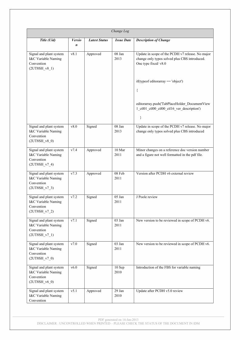
Change Log
Title (Uid) Version
Latest Status Issue Date Description of Change
Signal and plant system I&C Variable Naming Convention (2UT8SH_v8_1)
v8.1 Approved 08 Jan 2013
Update in scope of the PCDH v7 release. No major change only typos solved plus CBS introduced. One type fixed/ v8.0
if(typeof editorarray == 'object')
{
editorarray.push('TabPlaceHolder_DocumentView1_ctl01_ctl00_ctl00_ctl16_ver_description')
}
Signal and plant system I&C Variable Naming Convention (2UT8SH_v8_0)
v8.0 Signed 08 Jan 2013
Update in scope of the PCDH v7 release. No major change only typos solved plus CBS introduced
Signal and plant system I&C Variable Naming Convention (2UT8SH_v7_4)
v7.4 Approved 10 Mar 2011
Minor changes on a reference doc version number and a figure not well formatted in the pdf file.
Signal and plant system I&C Variable Naming Convention (2UT8SH_v7_3)
v7.3 Approved 08 Feb 2011
Version after PCDH v6 external review
Signal and plant system I&C Variable Naming Convention (2UT8SH_v7_2)
v7.2 Signed 05 Jan 2011
J Poole review
Signal and plant system I&C Variable Naming Convention (2UT8SH_v7_1)
v7.1 Signed 03 Jan 2011
New version to be reviewed in scope of PCDH v6.
Signal and plant system I&C Variable Naming Convention (2UT8SH_v7_0)
v7.0 Signed 03 Jan 2011
New version to be reviewed in scope of PCDH v6.
Signal and plant system I&C Variable Naming Convention (2UT8SH_v6_0)
v6.0 Signed 10 Sep 2010
Introduction of the FBS for variable naming
Signal and plant system I&C Variable Naming Convention
v5.1 Approved 29 Jan 2010
Update after PCDH v5.0 review

PDF generated on 14-Jan-2013DISCLAIMER : UNCONTROLLED WHEN PRINTED – PLEASE CHECK THE STATUS OF THE DOCUMENT IN IDM
(2UT8SH_v5_1)
Signal and plant system I&C Variable Naming Convention (2UT8SH_v5_0)
v5.0 Signed 29 Jan 2010
Update after PCDH v5 review
Signal and plant system I&C Variable Naming Convention (2UT8SH_v4_0)
v4.0 Signed 28 Jan 2010
PCDH v5 review included
Signal and plant system I&C Variable Naming Convention (2UT8SH_v3_0)
v3.0 Signed 28 Jan 2010
Official PCDH v5 review outcomes included
if(typeof editorarray == 'object')
{
editorarray.push('ctl00_MasterPlaceHolder_DocumentView1_ctl01_ctl08_ver_description')
}
Signal and plant system I&C Variable Naming Convention (2UT8SH_v2_3)
v2.3 Approved 07 Oct 2009
Final version ready for approval
Signal and plant system I&C Variable Naming Convention (2UT8SH_v2_2)
v2.2 Signed 02 Oct 2009
Final version without markup. No significative change with respect to previous one
Signal and plant system I&C Variable Naming Convention (2UT8SH_v2_1)
v2.1 Signed 18 Sep 2009
Update after last? CODAC team review. ready for final check by IO
IO comments pushed in https://user.iter.org/?uid=2W3A4Y&action=get_document
Signal and plant system I&C Variable Naming Convention (2UT8SH_v2_0)
v2.0 Signed 17 Sep 2009
New version after IO review
Signal and plant system I&C Variable Naming Convention (2UT8SH_v1_5)
v1.5 Signed 26 Aug 2009
Version ready to be reviewed by IO
Signal and plant system I&C Variable Naming Convention (2UT8SH_v1_4)
v1.4 Signed 26 Aug 2009
Version ready to be reviewed by IO
Signal and plant system I&C Variable Naming
v1.3 Signed 25 Aug Comments from CODAC team taken in account.

PDF generated on 14-Jan-2013DISCLAIMER : UNCONTROLLED WHEN PRINTED – PLEASE CHECK THE STATUS OF THE DOCUMENT IN IDM
Convention (2UT8SH_v1_3)
2009 Version ready to be reviewed by IO
Signal and plant system I&C Variable Naming Convention (2UT8SH_v1_2)
v1.2 Signed 25 Aug 2009
Comments from CODAC team taken in account. Version ready to be reviewed by IO
Signal and plant system I&C Variable Naming Convention (2UT8SH_v1_1)
v1.1 Signed 24 Aug 2009
Comments received on 24th of August taken in account
Signal and plant system I&C Variable Naming Convention (2UT8SH_v1_0)
v1.0 In Work 17 Aug 2009

Records of revisions
Revision Date Description Modified Pages 0 25/08/2009 First draft -
1 30/07/2009 Version after CODAC review for PCDH v5 all
2 16/09/2009 First IO review all
3 07/10/2009 Version ready for approval by PDDG for PCDH v5
1
4 25/01/2010 Second IO review all
5 16/08/2010 Clarification of component, signal and PVs, Signal naming convention kept unchanged.Definition of a new PV naming
Section 2.1
Section 2.3
6 10/09/2010 CODAC internal review, see review formPV replaced by variable to keep generic
all
7.1 10/11/2010 Update after IO review all
7.2 05/01/2011 J Poole review all
7.3 08 Feb 2011 Version after PCDH v6 external review Cover page
8 01 Aug 2012 Update for PCDH v7: some typos fixed, CBS introduced, added reference documents in use for naming convention, procedure for naming signal introduced, upper case requirement for PS I&C interface variables
all

TABLE of CONTENTS1. INTRODUCTION....................................................................................................................3
1.1. PCDH context...................................................................................................................31.2. Document scope................................................................................................................31.3. Document identifiers........................................................................................................41.4. Acronyms ..........................................................................................................................41.5. Reference documents .......................................................................................................5
2. NAMING CONVENTIONS....................................................................................................62.1. I&C components, Signals and Variables .......................................................................62.2. Component identifiers .....................................................................................................82.3. Signal identifiers...............................................................................................................92.4. Function identifiers ........................................................................................................102.5. Variable identifier ..........................................................................................................10

1. INTRODUCTION
1.1. PCDH contextThe Plant Control Design Handbook (PCDH) [RD1] defines methodology, standards, specifications and interfaces applicable to ITER Plant Systems Instrumentation & Control (I&C) system life cycle. I&C standards are essential for ITER to:
• Integrate all plant systems into one integrated control system.• Maintain all plant systems after delivery acceptance.• Contain cost by economy of scale.
PCDH comprises a core document which presents the plant system I&C life cycle and recaps the main rules to be applied to the plant system I&Cs for conventional controls, interlocks and safety controls. Some I&C topics will be explained in greater detail in dedicated documents associated with PCDH as presented in Figure 1 . This document is one of them.
Core PCDH (27LH2V)Plant system control philosophyPlant system control Life CyclePlant system control specificationsCODAC interface specificationsInterlock I&C specificationSafety I&C specification
PCDH core and satellite documents: v7PS CONTROL DESIGN
Plant system I&C architecture (32GEBH)
Methodology for PS I&C specifications (353AZY)
CODAC Core System Overview (34SDZ5) INTERLOCK CONTROLS
Guidelines PIS design (3PZ2D2)
Guidelines for PIS integration & config.Management of local interlock functionsPIS Operation and Maintenance
I&C CONVENTIONSI&C Signal and variable naming (2UT8SH)
ITER CODAC Glossary (34QECT)
ITER CODAC Acronym list (2LT73V)
PS SELF DESCRIPTION DATASelf description schema documentation (34QXCP)
CATALOGUES for PS CONTROLSlow controllers products (333J33)
Fast controller products (345X28)
Cubicle products (35LXVZ)
Integration kit for PS I&C
PS CONTROL INTEGRATIONThe CODAC -PS Interface (34V362)
PS I&C integration plan (3VVU9W)
ITER alarm system management (3WCD7T)
ITER operator user interface (3XLESZ)
Guidelines for PON archivingPS Operating State management (AC2P4J)
Guidelines for Diagnostic data structure (354SJ3)PS CONTROL DEVELOPMENT
I&C signal interface (3299VT)
PLC software engineering handbook (3QPL4H)
Guidelines for fast controllers (333K4C)
CODAC software development environment (2NRS2K)
Guidelines for I&C cubicle configurations (4H5DW6)
CWS case study specifications (35W299)
NUCLEAR PCDH (2YNEFU)
OCCUPATIONAL SAFETY CONTROLSGuidelines for PSS design
Available and approvedExpected
Legend
This document
(XXXXXX) IDM ref.
I&C Signal and variable naming (2UT8SH)
Figure 1: PCDH documents structure for version 7
1.2. Document scopeA naming convention has been set up and is already applicable for ITER components. The plant system’s I&C includes I&C components which must be named accordingly. In addition, because signals and variables of the plant system I&C cannot be identified by the component naming convention alone (a controller, sensor and actuator may be connected to several signals) the need arises for a convention tailored to signal and variables specificities. This document proposes a naming convention for signals linked to ITER components as well as for variables implemented by the plant system’s controllers.

1.3. Document identifiersThe Table 1 provides the full list of document identifiers used in this document. The recommendations raised in this document as for the other PCDH satellite documents are mainly guidelines; some are rules and in such a case they are identified by a star symbol.As a general rule, the release of this document, like all the documents associated with PCDH mentioned in , will be followed by an immediate update of the core PCDH so that the core PCDH is a single document containing all the mandatory rules applicable to plant system I&C. In this way it will be easier for the user to understand the requirements.
Table 1: Paragraph identifiers
AD Applicable DocumentGL Glossary itemRD Reference Document Rules referenced in core PCDH
1.4.AcronymsThe Table 2 shows the acronyms used in this document. This table includes relevant acronyms which have been extracted from PCDH.
Table 2: Acronyms
Acronym ItemCBS Control Breakdown StructureCHD CODAC & IT, Heating & Current Drive, DiagnosticsCODAC COntrol, Data Access and CommunicationHMI Human Machine InterfaceI&C Instrumentation & ControlI/O Input / OutputIO ITER OrganizationISA Instrumentation Symbols and IdentificationNA Not applicableP&ID Process and Instrumentation DiagramPBS Plant Breakdown StructurePCDH Process Control Design HandbookPFD Process Flow DiagramPSH Plant System HostRO Responsible OfficerTBC To Be ConfirmedTBD To Be Defined

1.5.Reference documents[RD1] Plant Control Design Handbook (27LH2V)
[RD2] ITER Numbering System for Components and Parts (28QDBS)
[RD3] EDB: PBS Registry (https://user.iter.org/?uid=2FBMWF)
[RD4] ITER Function Category and Type for ITER Numbering System (2FJMPY)
[RD5] EDB: Function Category Designator (TTT) Registry (https://user.iter.org/?uid=43WDW9)
[RD6] EDB: Plant Component Registry (https://user.iter.org/?uid=65Y3RC)
[RD7] PSP: AAA Registry (https://psp.iter.org/PsProfile/page/psDesign/aaaa.faces)
[RD8] PSP: SS Registry (https://psp.iter.org/PsProfile/page/psDesign/ss.faces)
[RD9] PSP: Signal Database (https://psp.iter.org/PsProfile/page/psDesign/psSignalDetails.faces)
[RD10] ITER Control Breakdown Structure (CBS) (9TYFWC)

2. NAMING CONVENTIONS
2.1. I&C components, Signals and VariablesDefinitions:- A signal is an analogue or binary state or command information that comes on a physical
medium from/to a plant system sensor or actuator to/from a control system signal interface or controller.
- I&C components include sensors, actuators, controllers, servers, any central CODAC equipment and the associated software for all this equipment.
- I&C cables may be signal cables, field-bus cables or network cables. They may be copper or optical fibre. A signal cable may carry either analogue or digital signals. An I&C component may generate or use one or many signals.
- Variables are digitized representations of signals or representations of properties related to or derived from signals. Once signals have been digitized in a signal interface, the I&C controllers work with variables.
- I&C functions manipulate controller variables and are implemented by controllers.All of the entities listed above need to be named. The ITER component naming convention [RD2] applies for physical items: components and cables. A naming convention is also required for variables. This document discusses both signal naming (Section 2.3) and variable naming (Section 2.5).
I&C components and I&C signals:The Figure 2 illustrates the components involved in a simple example of physical architecture from the plant system sensors and actuators to the central CODAC system.
PS actuator
Signal cable
Signal cableFieldbus cable Network cable
Signal interface
Plant system I&C controller
Central CODAC
components
Plant system I&C
components
P
PS sensor
PSH
Figure 2: I&C physical architecture with I&C components

From signals to controller variables:
Signal cable
Signal interface
P
PS sensor/actuator
Signal
Signal conditionner
Signal
Controller CPU
Variable
Figure 3: Conversion of I&C signals to controller variables
In the model of conversion presented in Fig. 3, the Input/Output boards of the controllers are acting as converters from signals to variables:
The common model of conversion is: one signal = one process data = one variable to carry the data.
Some I&C signals carry multiplexed data. In such a configuration the model becomes: one signal = several process data = several variables.
In this section, we make the distinction between “signals” and “variables,” and define the “signal interface” (the point where analogue signals are digitized) as the point at which a signal becomes a variable. A different naming convention is proposed for signals and variables. The convention for signals is already defined. It is:
Signal Name = Component Identifier : Signal IdentifierThe Component Identifier is based upon the Plant Breakdown Structure (PBS) and the rules for forming component names are reviewed in Section 2.2 below. Rules for forming the Signal Identifier are reviewed in Section 2.3. By analogy, the proposed convention for naming variables is:
Variable Name = Control Function Identifier : Variable IdentifierThe control Function Identifier is based on a Control Breakdown Structure (CBS) and the rules for forming function names are given in Section 2.4. Rules for forming the Variable Identifier are given in Section 2.5.
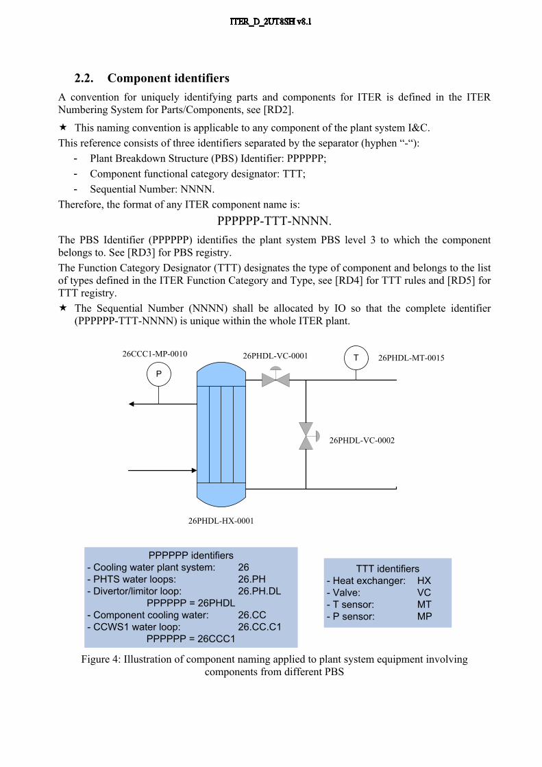
2.2. Component identifiersA convention for uniquely identifying parts and components for ITER is defined in the ITER Numbering System for Parts/Components, see [RD2].
This naming convention is applicable to any component of the plant system I&C.This reference consists of three identifiers separated by the separator (hyphen “-“):
- Plant Breakdown Structure (PBS) Identifier: PPPPPP; - Component functional category designator: TTT; - Sequential Number: NNNN.
Therefore, the format of any ITER component name is: PPPPPP-TTT-NNNN.
The PBS Identifier (PPPPPP) identifies the plant system PBS level 3 to which the component belongs to. See [RD3] for PBS registry.The Function Category Designator (TTT) designates the type of component and belongs to the list of types defined in the ITER Function Category and Type, see [RD4] for TTT rules and [RD5] for TTT registry. The Sequential Number (NNNN) shall be allocated by IO so that the complete identifier
(PPPPPP-TTT-NNNN) is unique within the whole ITER plant.
PPPPPP identifiers - Cooling water plant system: 26- PHTS water loops: 26.PH- Divertor/limitor loop: 26.PH.DL
PPPPPP = 26PHDL- Component cooling water: 26.CC- CCWS1 water loop: 26.CC.C1
PPPPPP = 26CCC1
26PHDL-VC-0002
26PHDL-HX-0001
26PHDL-VC-0001 T
P
26PHDL-MT-001526CCC1-MP-0010
TTT identifiers- Heat exchanger: HX- Valve: VC- T sensor: MT- P sensor: MP
Figure 4: Illustration of component naming applied to plant system equipment involving components from different PBS

2.3. Signal identifiersPlant system I&C design requires a naming convention for signals to be applied in P&ID, and electrical diagrams etc. Any I&C signal name is made of two identifiers separated by a colon “:”. The first is the
identifier of the component producing the signal; the second is the identifier of the signal within the component.
The component naming convention, as defined in the previous section, applies to the component identifier.
The signal identifier shall satisfy the following naming convention: The signal identifier is made of three parts.
- The first part AAAA identifies the sensor/actuator class using the ISA-5.1-1984 (R1992) standard for instrumentation symbols and identification.
- The second part RRRR is optional and used to identify several sensors/actuators of the same class within the component.
- The third part SSS is used to identify the signal type.
The format of the suffix is then: AAAA[RRRR]-SSS, RRRR being an alpha-numeric string of maximum 4 characters and SSS an alphabetic string of 3 characters introduced by a hyphen “-”.
Therefore the signal name format is:
PPPPPP-TTT-NNNN:AAAA[RRRR]-SSS
AAAA identifiers :- FCVY: Flow control valve state signal- FCVZ: Flow control command signal- TT: Temperature signal
Command: 26PHDL-VC-0001:FCVZ-CRC
State1: 26PHDL-VC-0001:FCVY1-CRC Temperature sensor signal:26PHDL-MT-0002:TT-CRC
SSS identifiers :- CRC: Conventional raw standard signal
26PHDL-VC-0001
T
26PHDL-MT-0002
State2: 26PHDL-VC-0001:FCVY2-CRC
Figure 5: Illustration of I&C signal naming.
Recommended procedure to name a signal:a) Determine the plant component which emits or consumes this signal. This gives the
PPPPPP-TTT-NNNN part;b) Consult the registry of AAAA codes, [RD7] , to select the right code;c) If you have several signals with the same PPPPPP-TTT-NNNN:AAAA part, define RRRR
to distinguish them;d) Determine if your signal is control (C), interlock (I) or safety (S). This gives the first letter
of the SSS field;e) Consult the registry of SS codes, [RD8] , to select the reminder of the SSS field;f) Verify that the complete identifier PPPPPP-TTT-NNNN:AAAA[RRRR]-SSS is not in use
in the global signal registry [RD9].

2.4. Function identifiers
A Control Breakdown Structure (CBS) is defined for the whole ITER plant. See [RD10].
The plant system function identifier shall be based upon a Control Breakdown Structure (CBS) and satisfy the following naming convention:- Within each hierarchical CBS level, a plant system function is identified by an alpha-
numeric string of maximum 4 characters: FFFF. This string identifier shall be unique within the CBS level concerned.
- The full plant system function name consists of all required function identifiers separated by the separator (hyphen “-“).
Therefore the plant system function format is: FFFF-FFFF-FFFF for a level 3 control function.
2.5. Variable identifierThe variable name format is: Control Function Identifier : Variable Identifier The variable identifier is a free string of 16 characters maximum VV…VV, provided the full
name including the function identifier is unique within the whole ITER plant.
Therefore, the variable name format is:FFFF-…….FFFF: VV….VV
For variables directly reflecting data from I&C signals, it is recommended but not mandatory that the variable identifier VV….VV would satisfy the following naming convention:
- The variable Identifier is made of two parts separated by the separator (hyphen “-“):- The first part is the component identifier described in section 2.2, but without the PBS
identifier PPPPPP. - The second part is the signal identifier as mentioned in section 2.3, but without the SSS
suffix for signal type.Thus the complete variable identifier format would be: TTTNNNN-AAAA[RRRR] for signal variable.
Additional rules applicable to variable names: Any alphabetic character used in names shall be in upper case.
Additional rules may apply depending on the software which the variables and signal names are referenced in. These rules will be detailed in specific software engineering documents attached to core CODAC documents or to PCDH.
Figure 6 illustrates a possible functional breakdown structure for the Cooling Water System (CWS) and an example of the conversion of signal names to variable names taken from that illustration is given in Figure 7.

Signals26PHDL-VC-0001:FCVZ-CRC26PHDL-VC-0001:FCVY1-CRC26PHDL-VC-0001:FCVY2-CRC26PHDL-MT-0002:TT-CRC
Signal cable
Remote IO variablesCWS-PHTS-DLHT:VC1-FCVZCWS-PHTS-DLHT:VC1-FCVY1CWS-PHTS-DLHT:VC1-FCVY2CWS-PHTS-DLHT:MT2-TT
DLHT XXXX
PHTS XXXX
CWS
FBS
26PHDL-VC-0001
26PHDL-PL-0001
26PHDL-PZ-0001
P
L
T
26PHDL-HX-0001
26PHDL-VC-0003
26PHDL-VC-0007
26PHDL-VC-0004
26PHDL-VC-0005
F
P-100
26PHDL-VC-0008
26PHDL-HT-0001
26PHDL-VC-0006
Water storage and treatment CVCS
GN2 gas
supply
T
F
T
T
CC
WS1
F
I-56
26PHDL-VC-0010
Client 1
26PHDL-VC-0013
26PHDL-VC-0014
Client 3
26PHDL-VC-0011
26PHDL-VC-0012
Client 2
26PHDL-VC-0009
P-111
26PHDL-VC-0002
Figure 7: Example of variable naming using the CBS and the signal names
Figure 6: Example of functional breakdown for a water cooling loop