method of manufacturing a piezoelectric device
TRANSCRIPT
center yoke 13L flows normal to and through coil 4L, then divides in the center hole of this coil fore and aft to front and rear south poles 14L and 15L, respectively. The right channel elements are the same but antipodal to these.mDSG
4,384,394
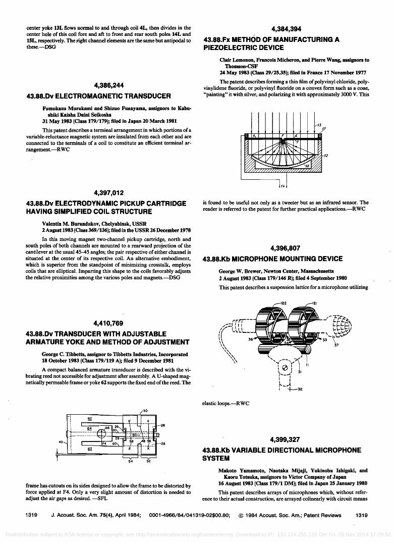
43.88.Fx METHOD OF MANUFACTURING A PIEZOELECTRIC DEVICE
4,386,244
43.88.Dv ELECTROMAGNETIC TRANSDUCER
Clair Lemonon, Francois Micheron, and Pierre Wang, assignors to Thomson-CSF
24 May 1983 {Class 29/2S.3S); filed in France 17 November 1977
The patent describes forming a thin film of polyvinyl chloride, poly- vinylidene fluoride, or polyvinyl fluoride on a convex form such as a cone, "painting" it with silver, and polarizing it with approximately 3000 V. This
Fumukazu Murukami and Shizuo Funayama, assignors to Kabu- shiki Kaisha Daini Seikosha
31 May 1983 (Class 179/179); filed in Japan 20 March 1981
This patent describes a terminal arrangement in which portions of a variable-reluctance magnetic system are insulated from each other and are connected to the terminals of a coil to constitute an efficient terminal ar-
rangement.mRWC
4,397,012
43.88.Dv ELECTRODYNAMIC PICKUP CARTRIDGE HAVING SIMPLIFIED COIL STRUCTURE
,55
is found to be useful not only as a tweeter but as an infrared sensor. The reader is referred to the patent for further practical applications.--RWC
Valentin M. Burundukov, Chelyabinsk, USSR 2 August 1983 (Class 369/136); filed in the USSR 26 December 1978
In this moving magnet two-channel pickup cartridge, north and south poles of both channels are mounted to a rearward projection of the cantilever at the usual 45-45 angles; the pair respective of either channel is situated at the center of its respective coil. An alternative embodiment, which is superior from the standpoint of minimizing crosstalk, employs coils that are elliptical. Imparting this shape to the coils favorably adjusts the relative proximities among the various poles and magnets.--DSG
4,396,807
43.88. Kb MICROPHONE MOUNTING DEVICE
George W. Brewer, Newton Center, Massachusetts 2 August 1983 (Class 179/146 R); filed 4 September 1980
This patent describes a suspension lattice for a microphone utilizing
4,410,769
43.88.Dv TRANSDUCER WITH ADJUSTABLE
ARMATURE YOKE AND METHOD OF ADJUSTMENT
George C. Tibbetts, assignor to Tibbetts Industries, Incorporated 18 October 1983 (Class 179/119 A); filed 9 December 1'981
A compact balanced armature transducer is described with the vi- brating reed not accessible for adjustment after assembly. A U-shaped mag- netically permeable frame or yoke 62 supports the fixed end of the reed. The
', I 6 .................. ---•.6 Jr 64 66202
'1i "-" .... 54 52
frame has cutouts on its sides designed to allow the frame to be distorted by force applied at F4. Only a very slight amount of distortion is needed to adjust the air gaps as desired. --SFL
elastic loops.--RWC
4,399,327
43.88. Kb VARIABLE DIRECTIONAL MICROPHONE SYSTEM
Makoto Yamamoto, Naotaka Mijaji, Yukinobu Ishigaki, and Kaoru Totsuka, assignors to Victor Company of Japan
16 August 1983 (Class 179/1 DM); filed in Japan 25 January 1980
This patent describes arrays of microphones which, without refer- ence to their actual construction, are arrayed colinearly with circuit means
1319 d. Acoust. Soc. Am. 75(4), April 1984; 0001-4966/84/041319-02500.80; ¸ 1984 Acoust. Soc. Am.; Patent Reviews 1319
Redistribution subject to ASA license or copyright; see http://acousticalsociety.org/content/terms. Download to IP: 132.174.255.116 On: Fri, 28 Nov 2014 17:29:50