metals engineering-------second class--...
TRANSCRIPT

Metals Engineering-------second class-- U.O.T
1. D.F.Baddley, J.A. Cannon-progressive Engineering Material-Hodder & stoughton-London-1988.
2. C.A. Chadwick, D.A. Smith-Grain Boundary structure and properties, Academic press London-1976.
3. F. Haessner-Recrystallization of metallic materials, Dr. Riederer Veriag Gmph. Stuttgart-1978.
4. S.K. Hajra choudhury-Materials science and processes, Indian book distributing Co.-1985.
5. R.A. Higgins-Engineerings Metallurgy, The English University press.LTD, fourth edition-1973.
6. R.W.K. Honey Combe-the plastic deformation of Metals, edward Arnold-1985.
7. D. Hull-Introduction of dislocation, pergamon press-1979. 8. R.S. Khurmi & R.S. Sedha- Materials science, S. Chand &
Company (Pvt) LTD-1987. 9. L. Kovacs, L. Zsoldos-dislocations and plastic deformation
pregamon press-1973.
10. W.C Leslie – the physical Metallargy of steel – Mc Graw – Hill International book Company-1982.
11.D.A. portor, K.E. Easterling-phase Transformation in Metals and Alloys Van Nostrand Reinhold (Uk) Co. LTD-1982.
12. V. Raghavan- Materials Science and Engineering-Prentice-Hall of India privete Limited-1985.
13. W.T. Read. Jr- Dislocation in crystals Mc Graw- Hill book company Inc.-1953. 14. R.E. Reed-Hill-Physical Metallurgy principles Van Nostrand-1973. 15. E.C. Rollason- Metallurgy for Engineers Edward Arnold fourth
edition-1980. 16. S.D. Sehgal, R.A. Lindberg-Materials, their Nature
properties&fabrication S. Chand & company (pvt) LTD-1975. 17. R.E. Smallman-Modern Physical Metallurgy Butter Worth
London- 4th edition-1985. 18. Thornton- -Fundamentals of Engineering Materials. 19. L.H. Van Vlack-Materials science for Engineers Addision-
Weseley. Pub.Co. Inc-1973. 20. J. wecrtman-Elementary dislocation theory-The Macmillan
Company-NewYork-1975.

21. W.A. Wood- The Study of metal structures and their mechanical property-pregamon Unified Engineering series-1971.
22. E.D Hondrros , M.P. seah, S.hofmann , and P.Lejcek , inphysical Metallurgy , edited by R.W. Cahn and P.haassen , 3rd ed.(north-holland , Amsterdam,1996 ) , Vo1.1.
23. A.P sutton and R.W. Balluffi , Interfaces in Crystallin solids (Oxford University press , New york , 1995)
24. Encyclopedia of Applied physics , edited by G.L. Trigg (VCM publishers , New york ,1992),Vo1.3.
25. j.p. Hirth and j.lothe: theory of Dislocations , (McGRAW-HILL Book company , New york , 1982) .
26. A.sutton and R.Balluffi , Interfaces in Crystallina Materials clarendon oxfoed , 1995).
27. M.Furtkamp , G.Gottstiein . D.A Molodov, V.N. Semenov and L.s. shvind erman : Acta Mater , Vol.46 (1998) P.4103
28. G.Gottstein and L.S. shvindlerman : Grain boundary migration in metals : thermodynamics , Kinetics , application (CRC press 1999)
29. G: Gottstein , U.Czubayko , D.A. Molodov , L.S Shvindlerman and W. Wunderlich : mater . Sci . forum Vol.204-206 (1996) Pp.99-108
30. MATERALS SCIENCE and ENGINEERING AN IN TRODUCTION fith Edition john willey & sons Inc 1999
31. Mikell P.Groover.
32. FUN DAMENTALS of Modern MANU FAC TURING ( Materials processes and Systems ) Johnwiley & sons Ins 1996
33. American Society for Metals (1987), "Alloy Phase Diagrams". Vol. 3, 2nd edition.
34. American Society for Metals (1987), "Heat Treatment". Vol. 4, 2nd edition.

Solid Solution Alloys:-
In certain alloys the complete solubility that exit in the liquid state, exit after the solidification. The solid alloys known as solid solution consist of one kind of crystal lattice structure. In which both metals however in the alloy is examine by microscopic. It is impossible intersect the two constituent a single phase structure exit. There are two types of solid solution alloys namely: Substitutional and Interstitial.
A) Substitutional Solid Solutions:- The atoms of the applied metal can be substitute for
those of that parent metal on the lattice. In such cases the metals must have nearly equal atomic diameter. Copper and Nickel are soluble in all proportions to form Substitutional Solid Solutions.
Figures explain formation of a Substitutional Solid
Solution alloy.

B)Interstitial Solid Solution:- The atoms of the added element inter the interstices
of the parent lattice. In other words, they fit into the spaces between the atoms of the parent metal this is of less common occurrence and is only possible if the atoms of the added element are small compare with those of the parent metal. Good example is that of carbon in iron to form that various step solid solutions.
Figures explain formation of an interstitial solid solution.
In certain alloys containing 3 metals not as ternary alloy, both types of solid solution may co-exit. For example, in austenitic manganese steel there is a substitutional solid solution of manganese and iron and also an interstitial solid solution of carbon in iron.


Interpretation of the simple eutectic diagram
Thermal equilibrium diagram of the simple eutectic
type

Thermal equilibrium diagram of the simple eutectic type
Let us consider a hypothetical simple eutectic diagram of two metals A,B. metal A melts at 700◦C and metal B melts at 500◦C, they form an eutectic contain 70%B, 30%A which melts at 300◦C. Consider the cooling of any alloy containing 30% B, the alloy contain more of metal A than required to form an eutectic upon reaching point (Q) on the liquidus (approximately 525◦C), crystal of metal A will be form as the temperature decreases more crystals of metal A are deposited and the liquid becomes progressively richer in metal B as represented by the liquidus (Q, E). At 400◦C the alloy will consist of solid metal A+ liquid of composition Z (47%A+53%). The relative weight of solid and liquid are given by relative line of the YZ & XY.
Weight of solid = YZ = 23 Weight of liquid = XY = 30
Upon reaching point R (300◦C) the liquid has attained the eutectic composition E (70%B, 30%A). At this temperature both metal A & B will crystallize simultaneously to form the eutectic structure. No farther changes will occur upon cooling to room temperature. The final microstructure will therefore consist of dendritic of metal A + eutectic.

All the alloys contain up to 70%B will consist of these two faces but the proportion of eutectic will increase with increasing contained of metal B. Alloys with greater than 70%B will commences to solidify by depositing metal B. The residual will become progressively rich with liquid A as the temperature force until reaches a composition 30%A, 70%B at 300◦C. At this temperature both metals will crystallize simultaneously as eutectic. The alloy of composition E will solidify entirely as eutectic at constant temperature 300◦C. It will be apparent that microscopic examination can be use to estimated the composition of any alloy. Examples of alloy system which give as to simple eutectic diagram (Bismuth- Cadmium), (Zinc-Tin), however most metals usually have a slight solid solubility, eutectic alloys are widely used for soldering and brazing and for casting cast.


Solid Solution Diagram:- • Phase: - a homogeneous aggregation of mater.
Every one notes that H2O can exit as a gas, a liquid and a solid. These are three different phases.
• Phase: - is a region of material that has uniform physical and chemical properties.

Solid Solution Diagram: -
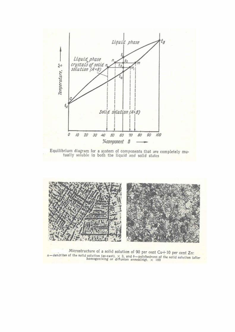
The equilibrium diagram of the solid solution type.
This diagram may be constructed in similar to that used for the simple eutectic type. Namely by going the first & second arrest points obtaining from series of cooling curves of alloys in the system. A typical solid solution type of diagram of is shown in the previous figure; the upper curve is the liguidus, and the lower curve is the solidus. Consider the cooling curve of an alloy of composition X, containing equal amounts of the two metals A & B. Solidification commences at T1 when a solid solution of composition S1 (richer in metal B than 50%) is deposited. Solidification proceeds by the absorption of metal A from the liquid when diffuses throw out the solid. Hence as the temperature falls from T1-T3, the solid solution changes its composition along the

solidus (S1-S3) and the liquid changes its composition along the liquidus (L1-L3) at T3. The alloy is completely solid and consists of uniform grains of solid solution of composition S3; the last drop of the liquid has the composition of L3. At some intermediate temperature T2, we have a solid solution of composition S2 in equilibrium with a liquid solution of composition L2. The relative weight of the solid & liquid are given by the relative lengths of the lines L2m & S2m. Weight of solid solution S2 = L2m Weight of liquid solution L2 = S2m Effect of cooling rate:-
It has been that the initial dendritic deposits are richer in metal B; the last liquid to solidify was richer in metal A. With slow cooling rates diffusion has time to occur producing a structure consisting of a single constitutor phase, similar to that of a pure metal. However in practice the cooling rate is too rabbit to allow diffusion to occur and this is not as cored structure results. Coring: - can be eliminated by annealing, when diffusion of the two metals occurs, for example binary solid solution alloys like copper-nickel, bismuth- antimony, and gold-silver.

Effect of annealing on the micro structure of a cast
solution alloy.

Combination Type Diagram:-
Equilibrium diagram of binary series of alloys in which two metals are partially soluble in each other
in the solid state.
This type of equilibrium diagram is really the combination of the two previous types. The liquidus line AEB is similar to that of the simple eutectic diagram. The solidus line in this diagram ACEDB and certain two parts namely AC and AB which are similar to the solidus line on that solid solution diagram. The solid solution of B in A and A in B increase with temperature as shown by the lines FC and GD respectively. The maximum solubility happens at the eutectic temperature, at the composition of the two solid solution α and β and denoted by the points C and D respectively. In this case the eutectic of composition E consist of the two solid solutions α and β. Consider the cooling of alloy of composition P, on the liquidus

line the solid solution of composition S will deposit. As the temperature fall to the eutectic temperature, the alloy will now consist of α of composition C and liquid of composition E. The liquid will solidify completely to form eutectic of the two solid solutions α and β in the proportion ED/EC=α/β, and upon farther cooling the α and β in the eutectic will become poorer in the metal B and A respectively. These compositions at room temperature are represented by F and G respectively. The primary dendrites of α solid solution will also become poorer in metal B changing in composition along CF and this will precipitate small amounts of β solid solution which is associated with the eutectic. Examples of the binary alloy system of this type are lead-tin, copper-silver and bismuth- tin alloys.


Micro Constituents of Steel:- Constituent of steel as seen under the microscope may
be classified as:- 1- Ferrite: - It is the name given to the grains or
crystals of solid solution of carbon in α iron. The solubility of carbon in α iron is 0.025% melted at 732◦C. When low carbon steel (less than 0.8% C) cool slowly from temperature above or within critical range, it consist chiefly of ferrite. (Properties) it is ductile, highly magnetic and it has a low tensile strength of approximately 2800 Kg/cm2.

2- Cementite: - It is a product which contains 6.67% carbon and 93.33% iron by weight. It is found in steel containing over 0.8% carbon when it cools slowly from (r just above) the critical alloy. The amount of cementite increase with increasing the percentage of carbon in iron. It is identify round particles in the structure. (Properties) it is extremely highly brittle and magnetic below 210 ◦C.
3- Pearlite: - It is a mechanical structure of about (87% ferrite + 13% cementite). It is found in all steels when cool slowly under 723 ◦C. Steel with 0.8% carbon is wholly pearlite. The soft steel contains less than 0.8% carbon containing ferrite + pearlite which is hard. Steel contains more than 0.8% carbon and (pearlite + cementite). The structure of pearlite consists of thin alternating plates of cementit and ferrite. (Properties) it is strong metal, may be cut reasonably well with cutting tool and it has tensile strength of 8750 Kg/cm2.
4- Austenite: - It is a solid solution of carbon or iron carbide (Fe3C) in γ iron. When low carbon steel is heated, its constituent remains particles "doesn't change" until reaching under the critical temperature 723 ◦C. At this temperature, the pearlite contain of the metal get completely changed into the new substance austenite. On farther heating the metal higher than the critical temperature, the remaining ferrite or cementite is observed by austenite. The maximum solubility of carbon in austenite is 1.7% at 1130 ◦C. (Properties) it is generally soft, ductile, non- magnetic and it is denser than ferrite.
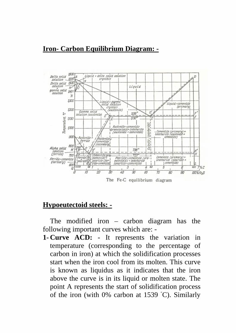
Iron- Carbon Equilibrium Diagram: -
Hypoeutectoid steels: -
The modified iron – carbon diagram has the following important curves which are: - 1- Curve ACD: - It represents the variation in
temperature (corresponding to the percentage of carbon in iron) at which the solidification processes start when the iron cool from its molten. This curve is known as liquidus as it indicates that the iron above the curve is in its liquid or molten state. The point A represents the start of solidification process of the iron (with 0% carbon at 1539 ◦C). Similarly

the point C represents the start of solidification processes of iron (with 4.3% carbon at 1130 ◦C). Also the point D represents the iron containing 6.7% carbon, I starts to solidify at a temperature higher than 1539 ◦C. This point is not of much particle important.
2- Curve AECF: - It also represents the variation in the temperature from A to E and ECF corresponding to the percentage of carbon in iron at which the solidification processes is completed when the iron is cold from its molten state. This curve is known as (solidus) as it indicates that the iron below this curve exit in solid state. The point A represents that the iron with the 0% carbon is solidify at 1539◦C. Similarly the points E, C and F indicate that the iron contain 0.7%, 4.3% and 6.7% carbon respectively solidify completely at 1130 ◦C.
3- Curve GSE: - It also represents the variation in temperature according to the percentage of carbon in the iron at which the transformation process from austenite into a mixture of austenite and ferrite or austenite and cementite starts, when the iron cool from a temperature above the curve GSE to a temperature below it. The points G, S and E represent the start of transformation process of iron with 0% carbon, 0.8% carbon and 1.7% carbon respectively.
4- Curve GPQ: - It also represents the variation in temperature (according to the percentage of carbon in iron) at which the transformation process from austenite to ferrite completed, when the iron cools from a temperature above the curve GP to a temperature below it. Similarly the curve PQ

represents the transformation of a little part of ferrite into cementite, while the remaining part remains as ferrite when the iron is farther cool from a temperature above the curve PQ to a temperature below it. The points G, P and Q represent the iron with 0% carbon, 0.025% carbon and 0.0025% carbon.
5- Curve PSK: - It represents a constant temperature line (corresponding to the percentage of carbon in iron) at which the transformation processes from a mixture of austenite and ferrite or austenite and cementite into a mixture of ferrite and cementite completed when the iron cool from a temperature above the curve PSK to a temperature below it. The points P, S and K represent the iron contain 0.025% carbon, 0.8% carbon and 6.67% carbon.
Notes: -
This graph, which is known as iron- carbon equilibrium diagram has the following important points: - 1- The percentage of carbon is between 0% and 6.67%. 2- Iron contains carbon from 0% to 1.7% known as
steel. 3- Steel contains carbon up to 0.8% known as
hypoeutectoid steel and the steel contains carbon from 0.8% to 1.7% known as hypereutectoid steel.
4- Iron contains carbon more than 1.7% known as cast iron.


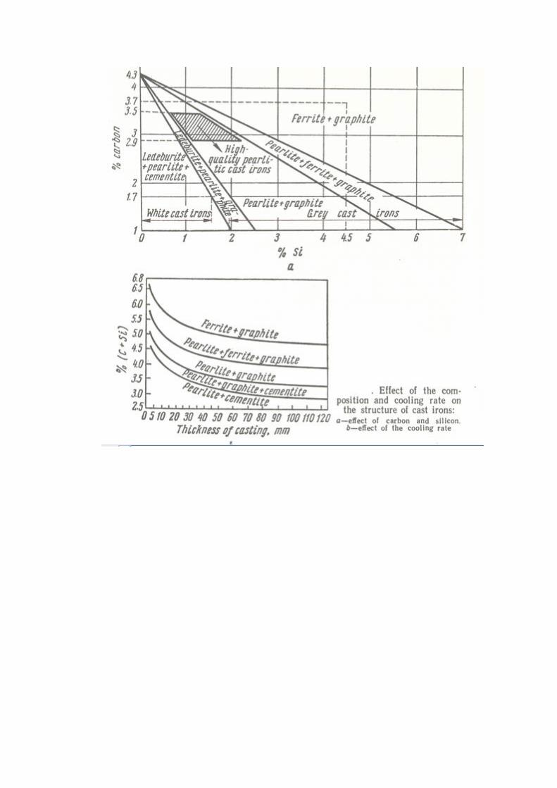
Cast Iron: -
In general contains 2-4% carbon which exit into two forms, either in the combine form as unstable iron carbide (Fe3C) known as cementite or in the free form known as graphite. Similar variations are possible with different properties. Specific types are as follows: - 1- White cast iron: - cast iron with (Fe3C) rather than
graphite. 2- Gray cast iron: - With graphite flakes and therefore
a gray fracture surface. 3- Malleable cast iron: - Cast iron that under goes
graphitization after solidification. Graphite exit as clusters.
4- Spheroidal graphite iron: - Cast iron in which graphite spheroids during solidification

Eutectic composition: - The composition of the liquid solution with the minimum melting temperature (at the intersection of the two liquid solubility curve). OR: - The composition of a liquid that acts to form two solids at the eutectic temperature. Eutectic temperature: - It is the melting temperature of any alloy with the eutectic composition. OR: - It is the temperature at the intersection of two liquid solubility curves. OR: - The temperature at which the liquid of eutectic composition freezes to form two solids simultaneously under equilibrium condition. OR: - The temperature at which the liquid and the solid are in equilibrium.