· metal oxide varistor(mov) metal oxide varistor(mov) applications surge protection in: consumer...
TRANSCRIPT


www.passivecomponent.com
Table of Contents
Varistors-5D Series ................................................................................................................................ 3
Varistors-7D Series ................................................................................................................................ 4
Varistors-10D Series .............................................................................................................................. 5
Varistors-14D Series .............................................................................................................................. 6
Varistors-20D Series .............................................................................................................................. 7
Varistors-25D Series .............................................................................................................................. 8
Varistors-5E、7E Series ........................................................................................................................ 9
Varistors-10E、14E Series ................................................................................................................... 10
Varistors-18E、20E Series ................................................................................................................... 11
V-I Curve ................................................................................................................................................ 12
Packing Specification (5Ø - 25Ø Series) ............................................................................................ 15
Taping Specifications - 5Ø and 7Ø ..................................................................................................... 16
Taping Specifications - 10Ø and 14Ø ................................................................................................. 17
Taping Specifications - 18Ø and 20Ø ................................................................................................. 18
Big Size Varistor - 32D Series .............................................................................................................. 19
Big Size Varistor - 34mm Single Series .............................................................................................. 20
Big Size Varistor - 34mm Dual Series ................................................................................................. 21
Big Size Varistor - 40D Series .............................................................................................................. 22
Big Size Varistor - 53D Series .............................................................................................................. 23
Packing of Big MOV and Soldering of MOV ....................................................................................... 25
Multilayer Chip Varistor(MLV) ............................................................................................................. 26
Subject PageSubject Page
INDEX
*�The�specifications�are�subject�to�change�or�our�products�in�it�may�be�discontinued�without�advance�notice.�Please�check�with�our�sales�representatives�or�product�engineers�before�ordering.*�This�catalog�has�only�typical�specifications�because�there�is�no�space�for�detailed�specifications.�Therefore,�please�approve�our�product�specifications�or�transact�the�approval�sheet�for�product�specification�before�ordering.�

1
www.passivecomponent.com
■ HOW TO ORDER
SR 241 K 10 D S 40 C X
Type Code
SR: Walsin�Varistor�
Varistor Voltage
�(DC�volt)�(From�180�to�112)�Two�significant�digits�Followed�by�no.�of�zeros�180=18volt�101=100volt�102=1000volt�
Tolerance
J:±5%
K:±10%�
Disk Size Code
05:5mm07:7mm10:10mm14:14mm18:18mm20:20mm25:25mm
Disk type
D:�Standard�disk�type
E:�High�energy�disk�type�
Lead Type or Taping Code
S�:�Straight�Lead�L�:�Inline�Crimped�O:�Outward�CrimpedI��:�Inward�Crimped�
Taping�Code�(Please�see�below)�
Lead Cutting
Lead�Cutting�for�Bulk�Packing:�A0=10±1.0mm�B0=19mm�minC0=29mm�min�D0=39mm�minE0=49mm�minF0=10mm�min�H0=30mm�min�G0=20mm�minL0=50mm�min�I0=40mm�minA5=15±1.0mm�G5=25mm�min
Coating
-P=Phenoliccoating�-B=Phenolic�coating�-S=Silicone�coating-F=HF�Epoxy�coating-Y=Without�coating-T=Epoxy�coating
Spacial Request
■�Special�����lead�cutting���tolerance■�Special�lead���spacing�(Please���see�below)■�Special�varistor���voltage����range...etc
*��If�customers�have�no�special�request�on�lead�shape,�we�provide�straight�lead�for�voltage�type�≤�471K�and�in-line�crimped�lead�for�voltage�type�≥�511K.
■ VARISTOR SPECIAL REQUEST F:0.5mm�lead�length�tolerance�for�short�lead�cutting�(exclude�straightlead)� � � � � � � �X:7.5mm�lead�spacing�for�20D�and�20E�(lead�wire�is�0.8mm�diameter)� � � � � � � � �Z:5mm�lead�spacing�for�10D(E),�14D(E)�H:Special�request�
■ DIMENSIONS QUICK REFERENCE :If�specific�item’s�dimensions,�please�contact�sales
Series 5D,5E 7D,7E 10D,10E 14D,14E 18E 20D,20E 25D
Dmax 7.0� 9.5� 12.0� 16.5� 20.0� 22.5� 28.0�d* 0.6� 0.6� 0.8� 0.8� 0.8� 1.0� 1.0�
W** 5.0� 5.0� 7.5� 7.5� 7.5� 10.0� 12.7�Hmax 12.5� 14.5� 19.0� 22.5� 26.0� 29.0� 36.5�H1max 10.0� 12.0� 17.0� 20.5� 24.0� 28.0� 34.0�Tmax 4.9� 4.9� 8.5� 8.5� 9.0� 9.0� 9.5�
�*�±0.02���**�±1.0� � � � � � � � � � � � ������(Unit:�mm)
Metal Oxide Varistor(MOV) Metal Oxide Varistor(MOV)
■ VARISTOR PART NUMBER EXAMPLES :Ex.1.� SR241K07DT14:�7mm,�241K,�inward�crimped�lead�and�reel� �taped.� � � �Ex.2.� SR361K10DI45:�10mm,�361K,�bulk�packing,�inward�crimped�� lead,lead�cutting�length�4.5�±1.0mm� �Ex.3.� SR621K20EOP2:�20mm,�621K,�high�energy,�bulk,�outward� �� crimped�lead,�lead�spacing�12mm±1.0mm.� �Ex.4.� SR271K20DO65X:�20mm,�271K,�bulk,�outward�crimped�lead,�� lead�spacing�7.5�mm,�lead�cutting�6.5�±�1.0mm� � �Ex.5.� SR241K10DS40F:�10mm,�241K,�bulk,�straight�lead,�lead�� cutting4.0�±�0.5mm.�
Remark:�� �The�lead�length�(L)�is�20mmminimum�unless�requested�by�customers;�please�refer�to�leadcutting�code�in�“How�to�Order”.� �

www.passivecomponent.com
2
■ CHARACTERISTICS■�High�performance�transient�voltage�suppression� � �■�Short�response�time�to�surge�voltage�■�Low�standby�power�dissipation■�Excellent�clamping�characteristics■�High�performance�withstanding�surge�currents■�High�reliability■�UL,�CSA,�VDE�and�CQC�recognized� � � �
■ DEFINITION OF VARISTOR TERMSRated RMS Voltage, Rated DC Voltage :The�maximum�designated�values�of�power�system�voltagethat�may�be�applied�continuously�between�the�terminals�of��a�device.�Varistor Voltage :Test�characteristic�that�is�used�to�classify�varistors�by�type.A�test�current�of�1mA�DC�is�typically�used�to�determinevaristor�voltage�classification�type.�Varistor�voltage�clamping�characteristics�can�be�defined�at�various�test�levels.Rated Peak Single Pulse Transient Current :Maximum�surge�current,�8/20�µs�waveform�which�a�varistor�israted�to�withstand�for�a�single�surge.Rated Single Pulse Transient Energy :Maximum�allowable�energy�for�a�single�impulse�(see�specifiedwaveforms).Maximum Clamping Voltage : Measured�peak�voltage�across�the�device�terminals�whena�current�impulse�of�specified�amplitude�and�waveform�isconducted�through�the�varistor.Typical Capacitance :Typical�capacitance�values�are�measured�at�a�test�frequencyof�1kHz.�Capacitance�values�are�only�for�reference�purpose�only,�not�subject�to�outgoing�inspection.
■ ENERGY DERATING VERSUS TEMPERATURE
Metal Oxide Varistor(MOV) Metal Oxide Varistor(MOV)
■ APPLICATIONS ■�Surge�protection�in:
■�Consumer�electronics■�Industrial�electronics■�Communication�electronics■�Measuring�and�controlling�systems■�Electronic�home�appliances
■�Protection�against�surges�induced�by�lighting�striking�incoming� � ��power�lines.
■�Suppression�of�surges�caused�by�switching�inductive�loads�suchas�transformers,�relays�and�coils.�
■�Protection�of�rectification�diodes,�SCRs,�power�transistors,� � ����semiconductor�devices,�etc�
■ GENERAL CHARACTERISTICS Storage Temperature :�–55˚C�to�+125˚COperating Surface Temperature :�125˚COperating Ambient Temperature :�–55˚C�to�+85˚C�(without�derating)Maximum Voltage-Temperature Coefficient :�<�–0.05%�/�˚CInsulation Resistance :�1000�Mega-ohm�minimumHi Pot (Leads To Case, 1 Min.) : 2500�VDCTypical Response Time :�<15�Nero-secondsEpoxy Rating : 94V-0Current / Energy Derating (>85˚C ) : –2.5%�/�˚CDC Leakage Current : 200µA�maximum�(at�rated�DC�working�voltage�)Solderability : MIL-STD-202FPower Dissipation Ratings(P, in-watts) :Disc�Size� 11Vac~40Vac� 50Vac~680Vac�5mm� 0.01� 0.157mm� 0.02� 0.2510mm� 0.05� 0.414mm� 0.1� 0.618mm� --� 0.820mm� 0.2� 1.025mm� --� 1.232mm� --� 1.634mm(single)� --� 2.134mm(dual)� --� 2.7340mm� --� 2.153mm� --� 2.5All�definitions�are�according�to�IEEE�specifications�C62.33.
■ PEAK CURRENT PER PULSE VERSUS PULSE DURATION
■ ■ Surge�protection�in:■ ■
■ ■
■ ■
■ ■
■ ■
■ ■
■
■
���������derating)
voltage�)
All�definitions�are�according�to�IEEE�specifications�C62.33.
�����DURATIONNumber of
Pulses on Order
From 100 %
Respectively :
18mm -- 0.8
10mm 0.05 0.414mm 0.1 0.6
Typical�capacitance�values�are�measured�at�a�test�frequency
50Vac~680VacDisc�Size 11Vac~40Vac5mm 0.01 0.157mm 0.02 0.25
waveforms).Maximum Clamping Voltage :Measured�peak�voltage�across�the�device�terminals�whena�current�impulse�of�specified�amplitude�and�waveform�isconducted�through�the�varistor.Typical Capacitance :
rated�to�withstand�for�a�single�surge.Rated Single Pulse Transient Energy :Maximum�allowable�energy�for�a�single�impulse�(see�specified
Typical Response Time : <15�Nero-secondsvaristor�voltage�classification�type.�Varistor�voltage�clampingcharacteristics�can�be�defined�at�various�test�levels.Rated Peak Single Pulse Transient Current :Maximum�surge�current,�8/20�µs�waveform�which�a�varistor�is
Solderability : MIL-STD-202FPower Dissipation Ratings(P, in-watts) :
Epoxy Rating : 94V-0Current / Energy Derating (>85˚C ) : –2.5% / ˚CDC Leakage Current : 200µA�maximum�(at�rated�DC�working
Operating Surface Temperature :�125˚C
Insulation Resistance : 1000�Mega-ohm�minimumHi Pot (Leads To Case, 1 Min.) :�2500�VDC
Test�characteristic�that�is�used�to�classify�varistors�by�type.A�test�current�of�1mA�DC�is�typically�used�to�determine
■�APPLICATIONS
Low�standby�power�dissipation Industrial�electronicsCommunication�electronics
Protection�of�rectification�diodes,�SCRs,�power�transistors,semiconductor�devices,�etc
Excellent�clamping�characteristicsHigh�performance�withstanding�surge�currentsHigh�reliabilityUL,�CSA,�VDE�and�CQC�recognized
■High�performance�transient�voltage�suppression
The�maximum�designated�values�of�power�system�voltagethat�may�be�applied�continuously�between�the�terminals�of�a�device.Varistor Voltage :
Suppression�of�surges�caused�by�switching�inductive�loads�suchas�transformers,�relays�and�coils.
Operating Ambient Temperature : –55˚C�to�+85˚C�(without
Maximum Voltage-Temperature Coefficient : < –0.05% / ˚C
Consumer�electronics
■�DEFINITION�OF�VARISTOR�TERMS ■�GENERAL�CHARACTERISTICSRated RMS Voltage, Rated DC Voltage : Storage Temperature : –55˚C�to�+125˚C
Short�response�time�to�surge�voltage
Measuring�and�controlling�systemsElectronic�home�appliances
Protection�against�surges�induced�by�lighting�striking�incomingpower�lines.
20mm 0.2 1.025mm -- 1.2
2.1
32mm -- 1.634mm(single) -- 2.1
53mm -- 2.5
of�1kHz.�Capacitance�values�are�only�for�reference�purposeonly,�not�subject�to�outgoing�inspection.
34mm(dual) -- 2.7340mm --
■�ENERGY�DERATING�VERSUS�TEMPERATURE ■�PEAK�CURRENT�PER�PULSE�VERSUS�PULSE
106 Pulses
1 Pulses10 Pulses102 Pulses103 Pulses104 Pulses105 Pulses

3
www.passivecomponent.com Varistors-5D Series Varistors-7D Series
Part Number
MaximumAllowable Voltage
VaristorVoltage
WithstandingSurge Current
(8/20 µs)
Max. Clamping Voltage (8/20 µs)
MaximumEngergy
TypicalCapacitance
SafetyApproval
Acrms DC DC Volts 1 time Vc Ip 2ms 10/1000µs @1kHz
Volts Volts Min Max Amps Volts Amps Joules pF
SR�180K05D□□ 11 14 16 20 100 36 1 0.4� 0.6� 1500 △
SR�220K05D□□ 14 18 20 24 100 43 1 0.6� 0.8� 1260 △
SR�270K05D□□ 17 22 24 30 100 53 1 0.7� 0.9� 1050 △
SR�330K05D□□ 20 26 30 36 100 65 1 0.9� 1.2� 850 △
SR�390K05D□□ 25 31 35 43 100 77 1 1.1� 1.3� 600 △
SR�470K05D□□ 30 38 42 52 100 93 1 1.4� 1.6� 500 △
SR�560K05D□□ 35 45 50 62 100 110 1 1.5� 1.9� 400 △
SR�680K05D□□ 40 56 61 75 100 135 1 1.8� 2.3� 360 △
SR�820K05D□□ 50 66 74 90 400 135 5 2.4� 3.0� 350 △
SR�101K05D□□ 60 85 90 110 400 165 5 2.4� 3.5� 320 △
SR�121K05D□□ 75 102 108 132 400 200 5 3.0� 5.0� 250 △
SR�151K05D□□ 95 127 135 165 400 250 5 3.5� 5.5 180 △
SR�181K05D□□ 120 160 170 207 400 320 5 4.2� 8.0� 155 △ ☆
SR�201K05D□□ 130 175 185 225 400 340 5 5.0� 8.5� 140 △ ☆
SR�221K05D□□ 140 180 198 242 400 360 5 6.0� 9.0� 125 △ ☆
SR�241K05D□□ 150 200 216 264 400 395 5 6.5� 10.0� 115 △ ☆
SR�271K05D□□ 180 230 255 311 400 475 5 7.5� 11.0� 105 △ ☆
SR�301K05D□□ 195 250 270 330 400 525 5 8.0� 11.5� 95 △ ☆
SR�331K05D□□ 210 275 297 363 400 540 5 8.5� 11.7� 85 △ ☆
SR�361K05D□□ 230 300 324 396 400 595 5 9.0� 13.0� 80 △ ☆
SR�391K05D□□ 250 330 351 429 400 650 5 10 15 75 △ ☆
SR�431K05D□□ 275 370 387 473 400 710 5 11 16 65 △ ☆
SR�471K05D□□ 300 385 423 517 400 775 5 13 19 55 △ ☆
SR�511K05D□□ 320 420 459 561 400 865 5 15 21 39 △ ☆
SR�561K05D□□ 360 470 522 638 400 960 5 17 25 36 △ ☆
SR�621K05D□□ 390 505 558 682 400 1040 5 19 27 33 △ ☆
SR�681K05D□□ 420 560 612 748 400 1120 5 21 30 30 △ ☆
Remark:� � � � � � � �1.�□□:�Suffix�adding;�please�refer�“How to Order”�for�details� � � � � � � �2.�All�parts�approved�as�follows:� � � � � � � �(1)�△: UL 1449,3rd�edition�recognized�(File�#�E309297).�� � � � � � � � � �(2)�☆ : CSA 22.2�#1�certified�(Certificate�File�#�LR109496-1).�� � � � � � � �(3)�CQC�recognized�for�all�part�numbers�(CQC04001010926)� � � � � � � �

www.passivecomponent.com
4
Varistors-5D Series Varistors-7D Series
Part Number
MaximumAllowable Voltage
VaristorVoltage
WithstandingSurge Current
(8/20 µs)
Max. Clamping Voltage (8/20 µs)
MaximumEngergy
TypicalCapacitance
SafetyApproval
Acrms DC DC Volts 1 time Vc Ip 2ms 10/1000µs @1kHz
Volts Volts Min Max Amps Volts Amps Joules pF
SR�180K07D□□ 11 14 16 20 250 36 2.5 0.8 1 2900 △ ◇
SR�220K07D□□ 14 18 20 24 250 43 2.5 0.9 1.3 2400 △ ◇
SR�270K07D□□ 17 22 24 30 250 53 2.5 1 1.4 1800 △ ◇
SR�330K07D□□ 20 26 30 36 250 65 2.5 1.2 1.7 1500 △ ◇
SR�390K07D□□ 25 31 35 43 250 77 2.5 1.5 2.1 1230 △ ◇
SR�470K07D□□ 30 38 42 52 250 93 2.5 1.8 2.5 950 △ ◇
SR�560K07D□□ 35 45 50 62 250 110 2.5 2.2 3.1 890 △ ◇
SR�680K07D□□ 40 56 61 75 250 135 2.5 2.5 3.8 850 △ ◇
SR�820K07D□□ 50 66 74 90 1200 135 10 3.5 5.5 830 △ ◇
SR�101K07D□□ 60 85 90 110 1200 165 10 4 6.5 730 △ ◇
SR�121K07D□□ 75 102 108 132 1200 200 10 5 7.8 570 △ ◇
SR�151K07D□□ 95 127 135 165 1200 250 10 6.5 9.7 400 △ ◇
SR�181K07D□□ 120 160 170 207 1200 300 10 8.8 12 305 △ ☆ ◇
SR�201K07D□□ 130 175 185 225 1200 340 10 10 13 275 △ ☆ ◇
SR�221K07D□□ 140 180 198 242 1200 360 10 11 14 250 △ ☆ ◇
SR�241K07D□□ 150 200 216 264 1200 395 10 11 16 230 △ ☆ ◇
SR�271K07D□□ 180 230 255 311 1200 455 10 12 18 205 △ ☆ ◇
SR�301K07D□□ 195 250 270 330 1200 505 10 13 19 185 △ ☆ ◇
SR�331K07D□□ 210 275 297 363 1200 540 10 14 20 170 △ ☆ ◇
SR�361K07D□□ 230 300 324 396 1200 595 10 15 25 155 △ ☆ ◇
SR�391K07D□□ 250 330 351 429 1200 650 10 17 26 145 △ ☆ ◇
SR�431K07D□□ 275 370 387 473 1200 710 10 20 28 130 △ ☆ ◇
SR�471K07D□□ 300 385 423 517 1200 775 10 21 30 115 △ ☆ ◇
SR�511K07D□□ 320 420 459 561 1200 850 10 23 32 88 △ ☆ ◇
SR�561K07D□□ 360 470 522 638 1200 960 10 27 39 85 △ ☆ ◇
SR�621K07D□□ 390 505 558 682 1200 1040 10 29 43 82 △ ☆ ◇
SR�681K07D□□ 420 560 612 748 1200 1120 10 32 45 78 △ ☆ ◇
Remark:� � � � � � � � � � � � �1.�□ □:�Suffix�adding;�please�refer�“How to Order”�for�details� � � � � � �2.�All�parts�approved�as�follows:� � � � � � � � � � �(1) △: UL 1449,3rd�edition�recognized�(File�#�E309297).�� � � � � � � � � �(2) ☆: CSA�22.2�#1�certified�(Certificate�File�#�LR109496-1).�� � � � � � � �(3) ◇: VDE/CECC�42000/42200/42201,�IEC�61051-1/61051-2/61051-2-2�(Certificate�#��40010090)� � � �(4)�CQC�recognized�for�all�part�numbers�(CQC04001010927)
5
www.passivecomponent.com Varistors-10D Series Varistors-14D Series
Part Number
MaximumAllowable Voltage
VaristorVoltage
WithstandingSurge Current
(8/20 µs)
Max. Clamping Voltage (8/20 µs)
MaximumEngergy
TypicalCapacitance
SafetyApproval
Acrms DC DC Volts 1 time Vc Ip 2ms 10/1000µs @1kHz
Volts Volts Min Max Amps Volts Amps Joules pF
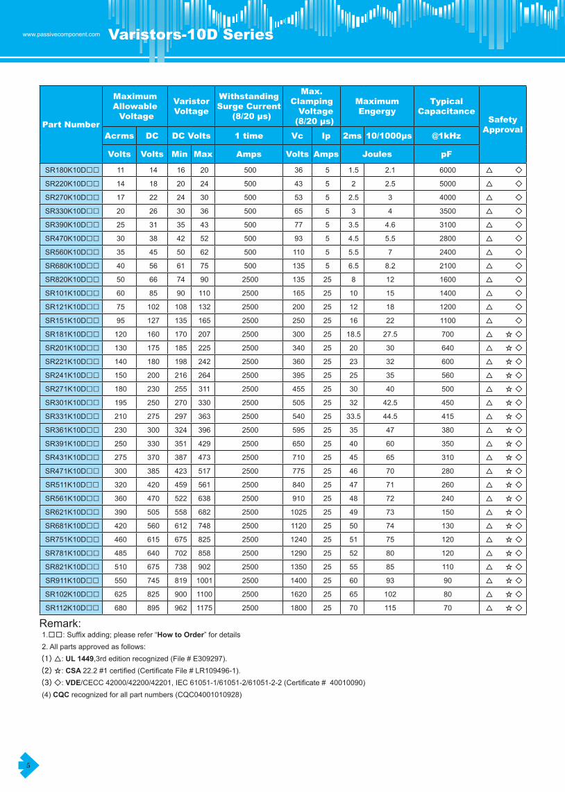
SR180K10D□□ 11 14 16 20 500 36 5 1.5 2.1 6000 △ ◇
SR220K10D□□ 14 18 20 24 500 43 5 2 2.5 5000 △ ◇
SR270K10D□□ 17 22 24 30 500 53 5 2.5 3 4000 △ ◇
SR330K10D□□ 20 26 30 36 500 65 5 3 4 3500 △ ◇
SR390K10D□□ 25 31 35 43 500 77 5 3.5 4.6 3100 △ ◇
SR470K10D□□ 30 38 42 52 500 93 5 4.5 5.5 2800 △ ◇
SR560K10D□□ 35 45 50 62 500 110 5 5.5 7 2400 △ ◇
SR680K10D□□ 40 56 61 75 500 135 5 6.5 8.2 2100 △ ◇
SR820K10D□□ 50 66 74 90 2500 135 25 8 12 1600 △ ◇
SR101K10D□□ 60 85 90 110 2500 165 25 10 15 1400 △ ◇
SR121K10D□□ 75 102 108 132 2500 200 25 12 18 1200 △ ◇
SR151K10D□□ 95 127 135 165 2500 250 25 16 22 1100 △ ◇
SR181K10D□□ 120 160 170 207 2500 300 25 18.5 27.5 700 △ ☆ ◇
SR201K10D□□ 130 175 185 225 2500 340 25 20 30 640 △ ☆ ◇
SR221K10D□□ 140 180 198 242 2500 360 25 23 32 600 △ ☆ ◇
SR241K10D□□ 150 200 216 264 2500 395 25 25 35 560 △ ☆ ◇
SR271K10D□□ 180 230 255 311 2500 455 25 30 40 500 △ ☆ ◇
SR301K10D□□ 195 250 270 330 2500 505 25 32 42.5 450 △ ☆ ◇
SR331K10D□□ 210 275 297 363 2500 540 25 33.5 44.5 415 △ ☆ ◇
SR361K10D□□ 230 300 324 396 2500 595 25 35 47 380 △ ☆ ◇
SR391K10D□□ 250 330 351 429 2500 650 25 40 60 350 △ ☆ ◇
SR431K10D□□ 275 370 387 473 2500 710 25 45 65 310 △ ☆ ◇
SR471K10D□□ 300 385 423 517 2500 775 25 46 70 280 △ ☆ ◇
SR511K10D□□ 320 420 459 561 2500 840 25 47 71 260 △ ☆ ◇
SR561K10D□□ 360 470 522 638 2500 910 25 48 72 240 △ ☆ ◇
SR621K10D□□ 390 505 558 682 2500 1025 25 49 73 150 △ ☆ ◇
SR681K10D□□ 420 560 612 748 2500 1120 25 50 74 130 △ ☆ ◇
SR751K10D□□ 460 615 675 825 2500 1240 25 51 75 120 △ ☆ ◇
SR781K10D□□ 485 640 702 858 2500 1290 25 52 80 120 △ ☆ ◇
SR821K10D□□ 510 675 738 902 2500 1350 25 55 85 110 △ ☆ ◇
SR911K10D□□ 550 745 819 1001 2500 1400 25 60 93 90 △ ☆ ◇
SR102K10D□□ 625 825 900 1100 2500 1620 25 65 102 80 △ ☆ ◇
SR112K10D□□ 680 895 962 1175 2500 1800 25 70 115 70 △ ☆ ◇
Remark:� � � � � � � � � � � � �1.□□:�Suffix�adding;�please�refer�“How to Order”�for�details� � � � � � � �2.�All�parts�approved�as�follows:� � � � � � � � � �(1) △: UL 1449,3rd�edition�recognized�(File�#�E309297).�� � � � � � � �(2) ☆: CSA 22.2�#1�certified�(Certificate�File�#�LR109496-1).�� � � � � � � �(3) ◇: VDE/CECC�42000/42200/42201,�IEC�61051-1/61051-2/61051-2-2�(Certificate�#��40010090)� � �(4) CQC�recognized�for�all�part�numbers�(CQC04001010928)� � � � � � � � �

www.passivecomponent.com
6
Varistors-10D Series Varistors-14D Series
Part Number
MaximumAllowable Voltage
VaristorVoltage
WithstandingSurge Current
(8/20 µs)
Max. Clamping Voltage (8/20 µs)
MaximumEngergy
TypicalCapacitance
SafetyApproval
Acrms DC DC Volts 1 time Vc Ip 2ms 10/1000µs @1kHz
Volts Volts Min Max Amps Volts Amps Joules pF
SR180K14D□□ 11 14 16 20 1000 36 10 3.5 4 15000 △ ◇ #
SR220K14D□□ 14 18 20 24 1000 43 10 4 5 12000 △ ◇ #
SR270K14D□□ 17 22 24 30 1000 53 10 5 6 8500 △ ◇ #
SR330K14D□□ 20 26 30 36 1000 65 10 6 7.5 7200 △ ◇ #
SR390K14D□□ 25 31 35 43 1000 77 10 7 8.6 6300 △ ◇ #
SR470K14D□□ 30 38 42 52 1000 93 10 8.5 10 5500 △ ◇ #
SR560K14D□□ 35 45 50 62 1000 110 10 10 11 4800 △ ◇ #
SR680K14D□□ 40 56 61 75 1000 135 10 12 14 4000 △ ◇ #
SR820K14D□□ 50 66 74 90 4500 135 50 15 22 3300 △ ◇ #
SR101K14D□□ 60 85 90 110 4500 165 50 20 30 2900 △ ◇ #
SR121K14D□□ 75 102 108 132 4500 200 50 22 34 2600 △ ◇ #
SR151K14D□□ 95 127 135 165 4500 250 50 30 45 2000 △ ◇ #
SR181K14D□□ 120 160 170 207 4500 300 50 33 53 1400 △ ☆ ◇ #
SR201K14D□□ 130 175 185 225 4500 340 50 38 60 1370 △ ☆ ◇ #
SR221K14D□□ 140 180 198 242 4500 360 50 40 60 1150 △ ☆ ◇ #
SR241K14D□□ 150 200 216 264 4500 395 50 45 66 1060 △ ☆ ◇ #
SR271K14D□□ 180 230 255 311 4500 455 50 52 72 950 △ ☆ ◇ #
SR301K14D□□ 195 250 270 330 4500 505 50 56 78 890 △ ☆ ◇ #
SR331K14D□□ 210 275 297 363 4500 545 50 63 87 800 △ ☆ ◇ #
SR361K14D□□ 230 300 324 396 4500 595 50 70 98 725 △ ☆ ◇ #
SR391K14D□□ 250 330 351 429 4500 650 50 72 102 665 △ ☆ ◇ #
SR431K14D□□ 275 370 387 473 4500 710 50 75 115 600 △ ☆ ◇ #
SR471K14D□□ 300 385 423 517 4500 775 50 80 125 570 △ ☆ ◇ #
SR511K14D□□ 320 420 459 561 4500 840 50 82 128 530 △ ☆ ◇ #
SR561K14D□□ 360 470 522 638 4500 910 50 85 139 480 △ ☆ ◇ #
SR621K14D□□ 390 505 558 682 4500 1025 50 88 142 270 △ ☆ ◇ #
SR681K14D□□ 420 560 612 748 4500 1120 50 90 142 240 △ ☆ ◇ #
SR751K14D□□ 460 615 675 825 4500 1240 50 100 143 210 △ ☆ ◇ #
SR781K14D□□ 485 640 702 858 4500 1290 50 105 148 205 △ ☆ ◇ #
SR821K14D□□ 510 675 738 902 4500 1350 50 110 157 200 △ ☆ ◇ #
SR911K14D□□ 550 745 819 1001 4500 1400 50 120 175 175 △ ☆ ◇ #
SR102K14D□□ 625 825 900 1100 4500 1620 50 130 190 145 △ ☆ ◇ #
SR112K14D□□ 680 895 962 1175 4500 1800 50 140 215 140 △ ☆ ◇ #
Remark:� � � � � � � � � � � � �1.�□□:�Suffix�adding;�please�refer�“How to Order”�for�details� � � � � � � �2. All parts approved as follows:
(1) △: UL 1449,3rd�edition�recognized�(File�#�E309297).�� � � � � � � � �(2) ☆: CSA 22.2�#1�certified�(Certificate�File�#�LR109496-1).�(3) ◇: VDE/CECC�42000/42200/42201,�IEC�61051-1/61051-2/61051-2-2�(Certificate�#��40010090)� � �(4)��#�:�VDE/IEC�60950-1,Annex�Q�(Certificate�#��40010090)�� � � � � � � �(5)�CQC�recognized�for�all�part�numbers�(CQC04001010929)� � � � � � � � �

7
www.passivecomponent.com Varistors-20D Series Varistors-25D Series
Part Number
MaximumAllowable Voltage
VaristorVoltage
WithstandingSurge Current
(8/20 µs)
Max. Clamping Voltage (8/20 µs)
MaximumEngergy
TypicalCapacitance
SafetyApproval
Acrms DC DC Volts 1 time Vc Ip 2ms 10/1000µs @1kHz
Volts Volts Min Max Amps Volts Amps Joules pF
SR390K20D□□ 25 31 35 43 2000 77 20 24 26 10000 △ ◇
SR470K20D□□ 30 38 42 52 2000 93 20 30 33 9350 △ ◇
SR560K20D□□ 35 45 50 62 2000 110 20 35 38 8000 △ ◇
SR680K20D□□ 40 56 61 75 2000 135 20 40 43 6800 △ ◇
SR820K20D□□ 50 66 74 90 6500 135 100 37 48 5600 △ ◇
SR101K20D□□ 60 85 90 110 6500 165 100 38 50 4700 △ ◇
SR121K20D□□ 75 102 108 132 6500 200 100 40 55 4100 △ ◇
SR151K20D□□ 95 127 135 165 6500 250 100 50 70 3200 △ ◇
SR181K20D□□ 120 160 170 207 6500 300 100 60 85 2500 △ ☆ ◇
SR201K20D□□ 130 175 185 225 6500 340 100 70 95 2200 △ ☆ ◇
SR221K20D□□ 140 180 198 242 6500 360 100 75 100 2000 △ ☆ ◇
SR241K20D□□ 150 200 216 264 6500 395 100 82 110 1900 △ ☆ ◇
SR271K20D□□ 180 230 255 311 6500 455 100 90 127 1700 △ ☆ ◇
SR301K20D□□ 195 250 270 330 6500 505 100 100 135 1540 △ ☆ ◇
SR331K20D□□ 210 275 297 363 6500 540 100 110 148 1400 △ ☆ ◇
SR361K20D□□ 230 300 324 396 6500 595 100 120 163 1320 △ ☆ ◇
SR391K20D□□ 250 330 351 429 6500 650 100 130 180 1210 △ ☆ ◇
SR431K20D□□ 275 370 387 473 6500 710 100 140 190 1120 △ ☆ ◇
SR471K20D□□ 300 385 423 517 6500 775 100 150 220 1000 △ ☆ ◇
SR511K20D□□ 320 420 459 561 6500 840 100 152 222 950 △ ☆ ◇
SR561K20D□□ 360 470 522 638 6500 910 100 154 226 900 △ ☆ ◇
SR621K20D□□ 390 505 558 682 6500 1025 100 158 228 770 △ ☆ ◇
SR681K20D□□ 420 560 612 748 6500 1120 100 160 230 700 △ ☆ ◇
SR751K20D□□ 460 615 675 825 6500 1240 100 175 255 640 △ ☆ ◇
SR781K20D□□ 485 640 702 858 6500 1290 100 180 265 590 △ ☆ ◇
SR821K20D□□ 510 675 738 902 6500 1350 100 190 282 510 △ ☆ ◇
SR911K20D□□ 550 745 819 1001 6500 1400 100 215 310 430 △ ☆ ◇
SR102K20D□□ 625 825 900 1100 6500 1620 100 230 342 380 △ ☆ ◇
SR112K20D□□ 680 895 962 1175 6500 1800 100 250 383 340 △ ☆ ◇
Remark:� � � � � � � � � � � � �1.�□□:�Suffix�adding;�please�refer�“How to Order”�for�details� � � � � � � �2.�All�parts�approved�as�follows:� � � � � � � � � �(1) △:UL 1449,3rd�edition�recognized�(File�#�E309297).�� � � � � �(2) ☆: CSA�22.2�#1�certified�(Certificate�File�#�LR109496-1).�� � � � � � � �(3) ◇: VDE/CECC�42000/42200/42201,�IEC�61051-1/61051-2/61051-2-2�(Certificate�#��40010090)� � � �(4) CQC�recognized�for�all�part�numbers�(CQC04001010931)� � � � � � � � �

www.passivecomponent.com
8
Varistors-20D Series Varistors-25D Series
Part Number
MaximumAllowable Voltage
VaristorVoltage
WithstandingSurge Current
(8/20 µs)
Max. Clamping Voltage (8/20 µs)
MaximumEngergy
TypicalCapacitance
SafetyApproval
Acrms DC DC Volts 1 time Vc Ip 2ms 10/1000µs @1kHz
Volts Volts Min Max Amps Volts Amps Joules pF
SR181K25D□□ 120 160 170 207 18000 300 100 90 180 3900 △ ☆
SR201K25D□□ 130 175 185 225 18000 340 100 100 200 3600 △ ☆
SR221K25D□□ 140 180 198 242 18000 360 100 105 225 3300 △ ☆
SR241K25D□□ 150 200 216 264 18000 395 100 110 235 3050 △ ☆
SR271K25D□□ 180 230 255 311 18000 455 100 120 245 2600 △ ☆
SR301K25D□□ 195 250 270 330 18000 505 100 125 255 2400 △ ☆
SR331K25D□□ 210 275 297 363 18000 545 100 130 270 2200 △ ☆
SR361K25D□□ 230 300 324 396 18000 595 100 160 315 2050 △ ☆
SR391K25D□□ 250 330 351 429 18000 650 100 175 342 1900 △ ☆
SR431K25D□□ 275 370 387 473 18000 710 100 190 370 1700 △ ☆
SR471K25D□□ 300 385 423 517 18000 775 100 200 390 1600 △ ☆
SR511K25D□□ 320 420 459 561 18000 840 100 210 422 1400 △ ☆
SR561K25D□□ 360 470 522 638 18000 910 100 215 460 1200 △ ☆
SR621K25D□□ 390 505 558 682 18000 1025 100 225 495 1800 △ ☆
SR681K25D□□ 420 560 612 748 18000 1120 100 230 515 1100 △ ☆
SR751K25D□□ 460 615 675 825 18000 1240 100 250 530 1000 △ ☆
SR781K25D□□ 485 640 702 858 18000 1290 100 260 540 980 △ ☆
SR821K25D□□ 510 675 738 902 18000 1350 100 270 550 920 △ ☆
SR911K25D□□ 550 745 819 1001 18000 1400 100 300 600 880 △ ☆
SR102K25D□□ 625 825 900 1100 18000 1620 100 340 630 760 △ ☆
SR112K25D□□ 680 895 962 1175 18000 1800 100 390 700 650 △ ☆
Remark:� � � � � � � �1.�□□:�Suffix�adding;�please�refer�“How to Order”�for�details� � � � � � � �2.�All�parts�approved�as�follows:� � � � � � � �(1) △: UL 1449,3rd�edition�recognized�(File�#�E309297).�� � � � � � � �(2) ☆: CSA�22.2�#1�certified�(Certificate�File�#�LR109496-1).�� � � � � � � �(3) CQC recognized�for�all�part�numbers�(CQC04001010932)� � � � � � � �

9
www.passivecomponent.com Varistors-5E/7E Series Varistors-10E/14E Series
Part Number
MaximumAllowable Voltage
VaristorVoltage
WithstandingSurge Current
(8/20 µs)
Max. Clamping Voltage (8/20 µs)
MaximumEngergy
TypicalCapacitance Safety
ApprovalAcrms DC DC Volts 1 time Vc Ip 10/1000µs @1kHz
Volts Volts Min Max Amps Volts Amps Joules pF
SR820K05E□□ 50 66 74 90 800 135 5 3.5 355 △
SR181K05E□□ 120 160 170 207 800 320 5 8 130 △
SR201K05E□□ 130 175 185 225 800 340 5 8.5 120 △ ☆
SR221K05E□□ 140 180 198 242 800 360 5 9 110 △ ☆
SR241K05E□□ 150 200 216 264 800 395 5 10.5 100 △ ☆
SR271K05E□□ 180 230 255 311 800 475 5 11 90 △ ☆
SR301K05E□□ 195 250 270 330 800 525 5 12 84 △ ☆
SR331K05E□□ 210 275 297 363 800 540 5 13 75 △ ☆
SR361K05E□□ 230 300 324 396 800 595 5 16 69 △ ☆
SR391K05E□□ 250 330 351 429 800 650 5 17 63 △ ☆
SR431K05E□□ 275 370 387 473 800 710 5 20 57 △ ☆
SR471K05E□□ 300 385 423 517 800 775 5 21 50 △ ☆
SR511K05E□□ 320 420 459 561 800 865 5 22 35 △
SR561K05E□□ 360 470 522 638 800 960 5 23 32 △
SR621K05E□□ 390 505 558 682 800 1040 5 25 30 △
SR681K05E□□ 420 560 612 748 800 1120 5 26 27 △
Remark:� � � � � � � � � � � � �1.�□□:�Suffix�adding;�please�refer�“How to Order”�for�details� � � � � � � �2. All parts approved as follows:
(1) △: UL 1449,3rd�edition�recognized�(File�#�E309297).�� � � � � � � � �(2) ☆: CSA�22.2�#1�certified�(Certificate�File�#�LR109496-5).�� � � � � � � �(3) ◇: VDE/CECC�42000/42200/42201,�IEC�61051-1/61051-2/61051-2-2�(Certificate�#��40003435)� � � �(4) # : VDE/IEC�60950-1,Annex�Q�(Certificate�#��40003435)�� � � � � � �(5)�CQC�recognized�for�all�part�numbers�(CQC04001010926�~�CQC04001010931)
Part Number
MaximumAllowable Voltage
VaristorVoltage
WithstandingSurge Current
(8/20 µs)
Max. Clamping Voltage (8/20 µs)
MaximumEngergy
TypicalCapacitance Safety
ApprovalAcrms DC DC Volts 1 time Vc Ip 10/1000µs @1kHz
Volts Volts Min Max Amps Volts Amps Joules pF
SR820K07E□□ 50 66 74 90 1750 135 10 7.0� 790 △ ◇
SR181K07E□□ 120 160 170 207 1750 320 10 16.0� 210 △ ◇
SR201K07E□□ 130 175 185 225 1750 340 10 17.5� 200 △ ☆ ◇
SR221K07E□□ 140 180 198 242 1750 360 10 19.0� 190 △ ☆ ◇
SR241K07E□□ 150 200 216 264 1750 395 10 21.0� 170 △ ☆ ◇
SR271K07E□□ 180 230 255 311 1750 475 10 24.0� 150 △ ☆ ◇
SR301K07E□□ 195 250 270 330 1750 525 10 26.0� 140 △ ☆ ◇
SR331K07E□□ 210 275 297 363 1750 540 10 28.0� 130 △ ☆ ◇
SR361K07E□□ 230 300 324 396 1750 595 10 32.0� 123 △ ☆ ◇
SR391K07E□□ 250 330 351 429 1750 650 10 35.0� 116 △ ☆ ◇
SR431K07E□□ 275 370 387 473 1750 710 10 40.0� 108 △ ☆ ◇
SR471K07E□□ 300 385 423 517 1750 775 10 42.0� 100 △ ☆ ◇
SR511K07E□□ 320 420 459 561 1750 865 10 46.0� 78 △ ◇
SR561K07E□□ 360 470 522 638 1750 960 10 47.0� 75 △ ◇
SR621K07E□□ 390 505 558 682 1750 1040 10 51.0� 72 △ ◇
SR681K07E□□ 420 560 612 748 1750 1120 10 57.0� 69 △ ◇
1.�□□:�Suffix�adding;�please�refer�“How to Order”�for�details� � ��� 2.�Safety�approval:�please�refer�to�"�Remark"�above.�

www.passivecomponent.com
10
Varistors-5E/7E Series Varistors-10E/14E Series
Part Number
MaximumAllowable Voltage
VaristorVoltage
WithstandingSurge Current
(8/20 µs)
Max. Clamping Voltage (8/20 µs)
MaximumEngergy
TypicalCapacitance Safety
ApprovalAcrms DC DC Volts 1 time Vc Ip 10/1000µs @1kHz
Volts Volts Min Max Amps Volts Amps Joules pF
SR820K10E□□ 50 66 74 90 3500 135 25 14 1780 △ ◇
SR181K10E□□ 120 160 170 207 3500 320 25 33 460 △ ◇
SR201K10E□□ 130 175 185 225 3500 340 25 35 430 △ ☆ ◇
SR221K10E□□ 140 180 198 242 3500 360 25 39 410 △ ☆ ◇
SR241K10E□□ 150 200 216 264 3500 395 25 42 380 △ ☆ ◇
SR271K10E□□ 180 230 255 311 3500 475 25 49 350 △ ☆ ◇
SR301K10E□□ 195 250 270 330 3500 525 25 53 320 △ ☆ ◇
SR331K10E□□ 210 275 297 363 3500 540 25 58 300 △ ☆ ◇
SR361K10E□□ 230 300 324 396 3500 595 25 65 285 △ ☆ ◇
SR391K10E□□ 250 330 351 429 3500 650 25 70 270 △ ☆ ◇
SR431K10E□□ 275 370 387 473 3500 710 25 80 255 △ ☆ ◇
SR471K10E□□ 300 385 423 517 3500 775 25 85 230 △ ☆ ◇
SR511K10E□□ 320 420 459 561 3500 865 25 92 210 △ ☆ ◇
SR561K10E□□ 360 470 522 638 3500 960 25 97 170 △ ☆ ◇
SR621K10E□□ 390 505 558 682 3500 1040 25 107 146 △ ☆ ◇
SR681K10E□□ 420 560 612 748 3500 1120 25 110 136 △ ☆ ◇
SR751K10E□□ 460 615 675 825 3500 1240 25 115 124 △ ☆ ◇
SR781K10E□□ 485 640 702 858 3500 1290 25 120 120 △ ☆ ◇
SR821K10E□□ 510 675 738 902 3500 1350 25 125 110 △ ☆ ◇
SR911K10E□□ 550 745 819 1001 3500 1400 25 130 90 △ ◇
SR102K10E□□ 625 725 900 1100 3500 1620 25 145 80 △ ◇
SR112K10E□□ 680 895 962 1175 3500 1800 25 155 70 △ ◇
1.�□□:�Suffix�adding;�please�refer�“How to Order”�for�details� ����������������2.�Safety�approval:�please�refer�to�"�Remark"�on�page�9.�
Part Number
MaximumAllowable Voltage
VaristorVoltage
WithstandingSurge Current
(8/20 µs)
Max. Clamping Voltage (8/20 µs)
MaximumEngergy
TypicalCapacitance Safety
ApprovalAcrms DC DC Volts 1 time Vc Ip 10/1000µs @1kHz
Volts Volts Min Max Amps Volts Amps Joules pF
SR820K14E□□ 50 66 74 90 6000 135 50 28 3310 △ ◇ #
SR181K14E□□ 120 160 170 207 6000 320 50 56 800 △ ◇ #
SR201K14E□□ 130 175 185 225 6000 340 50 70 770 △ ☆ ◇ #
SR221K14E□□ 140 180 198 242 6000 360 50 78 740 △ ☆ ◇ #
SR241K14E□□ 150 200 216 264 6000 395 50 84 700 △ ☆ ◇ #
SR271K14E□□ 180 230 255 311 6000 475 50 99 640 △ ☆ ◇ #
SR301K14E□□ 195 250 270 330 6000 525 50 107 620 △ ☆ ◇ #
SR331K14E□□ 210 275 297 363 6000 540 50 115 580 △ ☆ ◇ #
SR361K14E□□ 230 300 324 396 6000 595 50 140 540 △ ☆ ◇ #
SR391K14E□□ 250 330 351 429 6000 650 50 150 500 △ ☆ ◇ #
SR431K14E□□ 275 370 387 473 6000 710 50 165 460 △ ☆ ◇ #
SR471K14E□□ 300 385 423 517 6000 775 50 175 400 △ ☆ ◇ #
SR511K14E□□ 320 420 459 561 6000 865 50 190 350 △ ☆ ◇ #
SR561K14E□□ 360 470 522 638 6000 960 50 210 320 △ ☆ ◇ #
SR621K14E□□ 390 505 558 682 6000 1040 50 215 270 △ ☆ ◇ #
SR681K14E□□ 420 560 612 748 6000 1120 50 225 250 △ ☆ ◇ #
SR751K14E□□ 460 615 675 825 6000 1240 50 230 230 △ ☆ ◇ #
SR781K14E□□ 485 640 702 858 6000 1290 50 235 210 △ ☆ ◇ #
SR821K14E□□ 510 675 738 902 6000 1350 50 240 190 △ ☆ ◇ #
SR911K14E□□ 550 745 819 1001 6000 1400 50 255 170 △ ◇ #
SR102K14E□□ 625 725 900 1100 6000 1620 50 290 165 △ ◇ #
SR112K14E□□ 680 895 962 1175 6000 1800 50 310 140 △ ◇ #
1.�□□:�Suffix�adding;�please�refer�“How to Order”�for�details� � ���2.�Safety�approval:�please�refer�to�"�REMARK"�ON�PAGE�9.

11
www.passivecomponent.com Varistors-18E/20E Series V-I CURVE
Part Number
MaximumAllowable Voltage
VaristorVoltage
WithstandingSurge Current
(8/20 µs)
Max. ClampingVoltage
(8/20 µs)
MaximumEngergy
TypicalCapacitance
SafetyApprovalAcrms DC DC Volts 1 time Vc Ip 10/1000µs @1kHz
Volts Volts Min Max Amps Volts Amps Joules pF
SR820K18E□□ 50 66 74 90 8000 135 75 46 3500 △ ◇ #
SR181K18E□□ 120 160 170 207 9000 320 75 70 1600 △ ◇ #
SR201K18E□□ 130 175 185 225 9000 340 75 130 1270 △ ◇ #
SR221K18E□□ 140 180 198 242 9000 360 75 135 1220 △ ☆ ◇ #
SR241K18E□□ 150 200 216 264 9000 395 75 140 1200 △ ☆ ◇ #
SR271K18E□□ 180 230 255 311 9000 475 75 150 1050 △ ☆ ◇ #
SR301K18E□□ 195 250 270 330 9000 525 75 170 1010 △ ☆ ◇ #
SR331K18E□□ 210 275 297 363 9000 540 75 190 950 △ ☆ ◇ #
SR361K18E□□ 230 300 324 396 9000 595 75 215 870 △ ☆ ◇ #
SR391K18E□□ 250 330 351 429 9000 650 75 240 800 △ ☆ ◇ #
SR431K18E□□ 275 370 387 473 9000 710 75 260 730 △ ☆ ◇ #
SR471K18E□□ 300 385 423 517 9000 775 75 290 660 △ ☆ ◇ #
SR511K18E□□ 320 420 459 561 9000 865 75 314 570 △ ☆ ◇ #
SR561K18E□□ 360 470 522 638 9000 960 75 320 520 △ ☆ ◇ #
SR621K18E□□ 390 505 558 682 9000 1040 75 330 470 △ ☆ ◇ #
SR681K18E□□ 420 560 612 748 9000 1120 75 340 430 △ ☆ ◇ #
SR751K18E□□ 460 615 675 825 9000 1240 75 360 390 △ ☆ ◇ #
SR781K18E□□ 485 640 702 858 9000 1290 75 365 370 △ ☆ ◇ #
SR821K18E□□ 510 675 738 902 9000 1350 75 388 310 △ ☆ ◇ #
SR911K18E□□ 550 745 819 1001 9000 1400 75 405 280 △ ☆ ◇ #
SR102K18E□□ 625 725 900 1100 9000 1620 75 450 250 △ ☆ ◇ #
SR112K18E□□ 680 895 962 1175 9000 1800 75 500 230 △ ☆ ◇ #
1.�□□:�Suffix�adding;�please�refer�“How to Order”�for�details� � 2.�Safety�approval:�please�refer�to�"�Remark"�on�page�9.�
Part Number
MaximumAllowable Voltage
VaristorVoltage
WithstandingSurge Current
(8/20 µs)
Max. Clamping Voltage (8/20 µs)
MaximumEngergy
TypicalCapacitance
SafetyApprovalAcrms DC DC Volts 1 time Vc Ip 10/1000µs @1kHz
Volts Volts Min Max Amps Volts Amps Joules pF
SR820K20E□□ 50 66 74 90 10000 135 100 56 5300 △ ◇ #
SR181K20E□□ 120 160 170 207 12000 320 100 135 1800 △ ◇ #
SR201K20E□□ 130 175 185 225 12000 340 100 140 1700 △ ☆ ◇ #
SR221K20E□□ 140 180 198 242 12000 360 100 155 1600 △ ☆ ◇ #
SR241K20E□□ 150 200 216 264 12000 395 100 170 1500 △ ☆ ◇ #
SR271K20E□□ 180 230 255 311 12000 475 100 190 1300 △ ☆ ◇ #
SR301K20E□□ 195 250 270 330 12000 525 100 210 1200 △ ☆ ◇ #
SR331K20E□□ 210 275 297 363 12000 540 100 228 1100 △ ☆ ◇ #
SR361K20E□□ 230 300 324 396 12000 595 100 275 1050 △ ☆ ◇ #
SR391K20E□□ 250 330 351 429 12000 650 100 305 1000 △ ☆ ◇ #
SR431K20E□□ 275 370 387 473 12000 710 100 330 950 △ ☆ ◇ #
SR471K20E□□ 300 385 423 517 12000 775 100 350 900 △ ☆ ◇ #
SR511K20E□□ 320 420 459 561 12000 865 100 382 800 △ ☆ ◇ #
SR561K20E□□ 360 470 522 638 12000 960 100 395 760 △ ☆ ◇ #
SR621K20E□□ 390 505 558 682 12000 1040 100 410 710 △ ☆ ◇ #
SR681K20E□□ 420 560 612 748 12000 1120 100 423 670 △ ☆ ◇ #
SR751K20E□□ 460 615 675 825 12000 1240 100 435 620 △ ☆ ◇ #
SR781K20E□□ 485 640 702 858 12000 1290 100 450 580 △ ☆ ◇ #
SR821K20E□□ 510 675 738 902 12000 1350 100 460 530 △ ☆ ◇ #
SR911K20E□□ 550 745 819 1001 12000 1400 100 510 470 △ ☆ ◇ #
SR102K20E□□ 625 725 900 1100 12000 1620 100 560 425 △ ☆ ◇ #
SR112K20E□□ 680 895 962 1175 12000 1800 100 620 380 △ ☆ ◇ #
1.�□□:�Suffix�adding;�please�refer�“How to Order”�for�details� � � 2.�Safety�approval:�please�refer�to�"�Remark"�on�page�9.�

www.passivecomponent.com
12
Varistors-18E/20E Series V-I CURVE

13
www.passivecomponent.com V-I CURVE V-I CURVE

www.passivecomponent.com
14
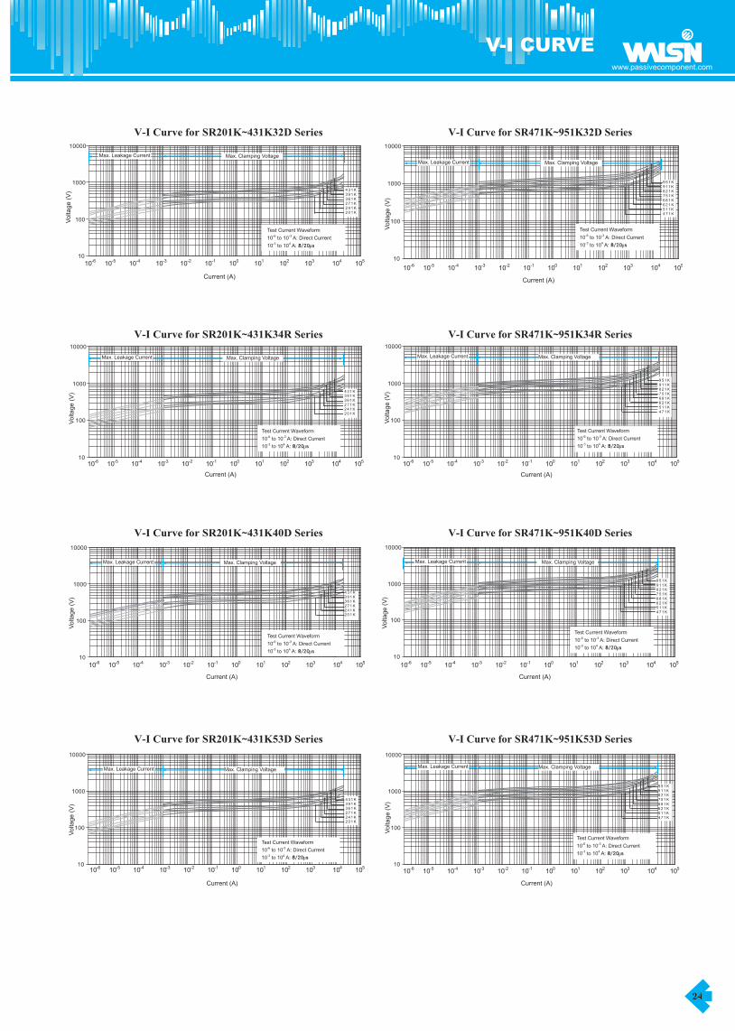
V-I CURVE V-I CURVE
15
www.passivecomponent.com
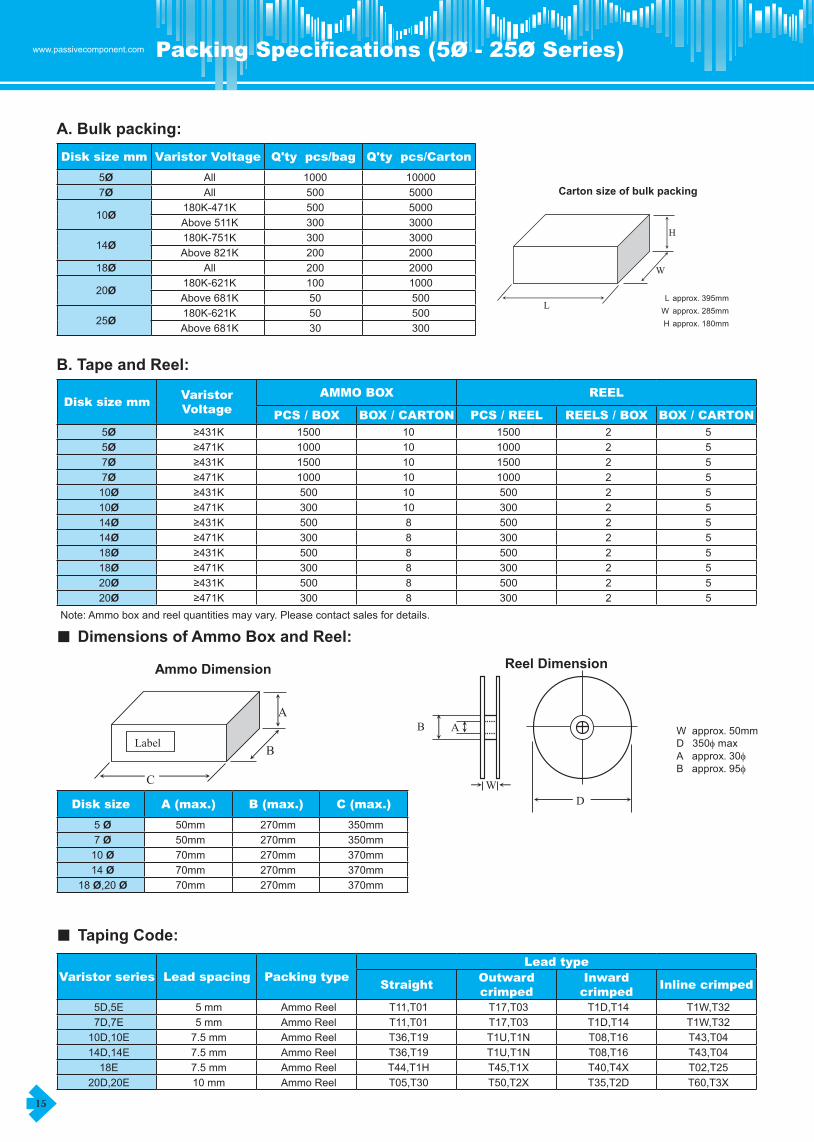
A. Bulk packing: Disk size mm Varistor Voltage Q'ty pcs/bag Q'ty pcs/Carton
5Ø All 1000 100007Ø All 500 5000
10Ø180K-471K 500 5000Above�511K 300 3000
14Ø180K-751K 300 3000Above�821K 200 2000
18Ø All 200 2000
20Ø180K-621K 100 1000Above�681K 50 500
25Ø180K-621K 50 500Above�681K 30 300
B. Tape and Reel:
Disk size mmVaristor Voltage
AMMO BOX REEL
PCS / BOX BOX / CARTON PCS / REEL REELS / BOX BOX / CARTON5Ø ≥431K 1500 10 1500 2 55Ø ≥471K 1000 10 1000 2 57Ø ≥431K 1500 10 1500 2 57Ø ≥471K 1000 10 1000 2 510Ø ≥431K 500 10 500 2 510Ø ≥471K 300 10 300 2 514Ø ≥431K 500 8 500 2 514Ø ≥471K 300 8 300 2 518Ø ≥431K 500 8 500 2 518Ø ≥471K 300 8 300 2 520Ø ≥431K 500 8 500 2 520Ø ≥471K 300 8 300 2 5
Note:�Ammo�box�and�reel�quantities�may�vary.�Please�contact�sales�for�details.�
■ Dimensions of Ammo Box and Reel:
Disk size A (max.) B (max.) C (max.)
5 Ø 50mm 270mm 350mm7�Ø 50mm 270mm 350mm10�Ø 70mm 270mm 370mm14�Ø 70mm 270mm 370mm
18�Ø,20�Ø 70mm 270mm 370mm
■ Taping Code:
Varistor series Lead spacing Packing typeLead type
StraightOutward crimped
Inward crimped
Inline crimped
5D,5E 5 mm Ammo�Reel T11,T01 T17,T03 T1D,T14 T1W,T327D,7E 5 mm Ammo�Reel T11,T01 T17,T03 T1D,T14 T1W,T3210D,10E 7.5�mm Ammo�Reel T36,T19 T1U,T1N T08,T16 T43,T0414D,14E 7.5�mm Ammo�Reel T36,T19 T1U,T1N T08,T16 T43,T0418E 7.5�mm Ammo�Reel T44,T1H T45,T1X T40,T4X T02,T25
20D,20E 10�mm Ammo�Reel T05,T30 T50,T2X T35,T2D T60,T3X
A. Bulk packing:Carton size of bulk packing
L approx.�395mmW approx.�285mmH approx.�180mm
B. Tape and Reel:
Note:�Ammo�box�and�reel�quantities�may�vary.�Please�contact�sales�for�details.
■ Dimensions of Ammo Box and Reel:Ammo Dimension Reel Dimension
■ Taping Code:
5
2 5
2 52 5
52 52 52 5
52 52 52 5
88888
2
2
2300500300
1010101010108
300
1500100015001000500300500300500
20f
20f
1000500300500300500300500
10f
10f
14f
14f
18f
18f
≦431K≧471K≦431K≧471K≦431K≧471K
150010001500
BOX / CARTON
≦431K≧471K
BOX / CARTONDisk size mm Varistor Voltage
PCS / BOX
AMMO BOX REEL
PCS / REEL REELS / BOX
200020001000500500300
Q'typcs/Carton
10000
5000500030003000
1000
500500
505030
100
Varistor VoltageAll
All180K-471K
300300200200
Q'ty pcs/bag
20f
25f
Above�511K180K-751KAbove�821K
All180K-621KAbove�681K180K-621KAbove�681K
≧471K
5f
5f
7f
7f
≦431K≧471K≦431K
Disk size5 f7 f10 f
Disk size mm
5f
7f
14f
10f
18f
C (max.)50mm 270mm 350mm
A (max.) B (max.)
350mm70mm 270mm 370mm50mm 270mm
20D,20E 10�mm
370mm70mm 270mm 370mm
14 f18 f, f
70mm 270mm
5D,5E 5 mm7D,7E 5 mm
14D,14E 7.5�mm
Varistor series
T1W,T32Straight Outward crimped Inward crimped Inline crimped
T17,T03Ammo�Reel T11,T01 T1D,T14T11,T01 T17,T03 T1D,T14
Lead typePacking typeLead spacing
T08,T16
T1W,T3210D,10E 7.5�mm Ammo�Reel T36,T19 T1U,T1N T08,T16 T43,T04
Ammo�Reel
18E 7.5�mm Ammo�Reel T44,T1H T45,T1X T40,T4XT60,T3XAmmo�Reel T05,T30 T50,T2X T35,T2D
T43,T04T02,T25
Ammo�Reel T36,T19 T1U,T1N
L
W
H
C
B
A
Label
WD
W��approx.�50mmD���350f maxA���approx.�30fB���approx.�95f
AB
Packing Specifications (5Ø - 25Ø Series) Taping Specifications - 5Ø and 7Ø

www.passivecomponent.com
16
D
d
P
P0
P1
F
Δ h
W
W0
W1
W2
H1
H0
LX
D0
t
L
A
P2
11Max 11Max
6.35±0.7 6.35±0.7
*�Tolerances�are�+1.0�and�-0.5
All�dimensions�are�in�millimeters.
6.35±0.7 6.35±0.7 6.35±0.7 6.35±0.7
— 13Max 13Max — 15Max 15Max
11Max 11Max
4±0.2 4±0.2
<�0.7 <�0.7
11Max 11Max
4±0.2 4±0.2 4±0.2 4±0.2
<�0.7 <�0.7 <�0.7 <�0.7
16±0.5 16±0.5
1.0Max 1.0Max 1.0Max 1.0Max 1.0Max 1.0Max
— 16±0.5 16±0.5 —
1.5Max
30Max 30Max 30Max 32Max 32Max 30Max
1.5Max 1.5Max 1.5Max 1.5Max
10Min
9±0.5 9±0.5
2.0Max
10Min 10Min 10Min 10Min
9±0.5 9±0.5 9±0.5 9±0.5
3.85±0.7
2.0Max
18* 18* 18* 18* 18* 18*
2.0Max 2.0Max
12.7±1
2.0Max
3.85±0.7
5.0±0.8 5.0±0.8 5.0±0.8 5.0±0.8 5.0±0.8
3.85±0.7 3.85±0.7
9Max
3.85±0.7
12.7±1
12.7±0.3 12.7±0.3 12.7±0.3 12.7±0.3 12.7±0.3
12.7±1 12.7±1
10Min
12.7±1
9Max
0.6 0.6 0.6 0.6 0.6
7Max 7Max
Length�of�Clipped�Lead
9Max
Hole�Center�to�Component�Center
7Max
0.6
12.7±1
12.7±0.3
3.85±0.7
5.0±0.8
2.0Max
T32,�T1W
Component�Alignment
Base�paper�Tape�Width
Adhesive�Tape�Width
Hole�Position
Component�Height�from�Seating�Plane
Adhesive�Tape�Border
Component�Height
Lead-Wire�Clinch�Height
Lead-Wire�Protrusion
Based�on�EIA-468-B�Specification
Body�Diameter
Lead�Wire�Diameter
Pitch�of�Component
Feed�Hole�Pitch
Feed�Hole�Center�to�LeadLead�to�Lead�Distance�(Center�toCenter)
1.5Max
Feed�Hole�Diameter
Total�Tape�Thickness
7Φ (7D, 7E)5Φ (5D, 5E)Disk Size
Item
Taping�Code T11,�T01 T17,�T03,�T14,T1D T32,�T1W T11,�T01 T17,�T03,�T14,�T1D
P
P0
Fd
D0
H0
W1 WW
0W
2
DH
1
LX
A
L
P2
Δh
P1
T17(Ammo��Box)T03(Reel)
P
P0
Fd
D0
H0
W1 WW
0W
2
D
H1
LX
A
L
P2
ΔhT1D(Ammo��Box)T14(Reel)
P1
P
P0
Fd
D0
H0
W1 WW
0W
2
D
H1
LX
A
L
P2
T1W(Ammo��Box)T32(Reel)
P1
Δh
Packing Specifications (5Ø - 25Ø Series) Taping Specifications - 5Ø and 7Ø
ItemDisk Size
5Ø (5D, 5E) 7Ø (7D, 7E)
Taping�Code T11,�T01 T17,�T03,�T14,�T1D T32,�T1W T11,�T01 T17,�T03,�T14,�T1D T32,�T1WBody�Diameter D 7Max 7Max 7Max 9Max 9Max 9MaxLead�Wire�Diameter d 0.6 0.6 0.6 0.6 0.6 0.6Pitch�of�Component P 12.7±1 12.7±1 12.7±1 12.7±1 12.7±1 12.7±1Feed�Hole�Pitch P0 12.7±0.3 12.7±0.3 12.7±0.3 12.7±0.3 12.7±0.3 12.7±0.3Feed�Hole�Center�to�Lead P1 3.85±0.7 3.85±0.7 3.85±0.7 3.85±0.7 3.85±0.7 3.85±0.7Lead�to�Lead�Distance�(Center�to�Center) F 5.0±0.8 5.0±0.8 5.0±0.8 5.0±0.8 5.0±0.8 5.0±0.8Component�Alignment Δh 2.0Max 2.0Max 2.0Max 2.0Max 2.0Max 2.0MaxBase�paper�Tape�Width W 18* 18* 18* 18* 18* 18*Adhesive�Tape�Width W0 10Min 10Min 10Min 10Min 10Min 10MinHole�Position W1 9±0.5 9±0.5 9±0.5 9±0.5 9±0.5 9±0.5Adhesive�Tape�Border W2 1.5Max 1.5Max 1.5Max 1.5Max 1.5Max 1.5MaxComponent�Height H1 30Max 30Max 30Max 32Max 32Max 30MaxLead-Wire�Clinch�Height H0 — 16±0.5 16±0.5 — 16±0.5 16±0.5Lead-Wire�Protrusion Lx 1.0Max 1.0Max 1.0Max 1.0Max 1.0Max 1.0MaxFeed�Hole�Diameter D0 4±0.2 4±0.2 4±0.2 4±0.2 4±0.2 4±0.2Total�Tape�Thickness t <�0.7 <�0.7 <�0.7 <�0.7 <�0.7 <�0.7Length�of�Clipped�Lead L 11Max 11Max 11Max 11Max 11Max 11MaxComponent�Height�from�Seating�Plane A — 13Max 13Max — 15Max 15MaxHole�Center�to�Component�Center P2 6.35±0.7 6.35±0.7 6.35±0.7 6.35±0.7 6.35±0.7 6.35±0.7Based�on�EIA-468-B�Specification� � � � � � � � *�Tolerances�are�+1.0�and�-0.5��All�dimensions�are�in�millimeters.� � � � � � � � � � � �
T17(Ammo�Box)T03(Reel)
T1D(Ammo�Box)T14(Reel)
T1W(Ammo�Box)T32(Reel)
T11(Ammo�Box)T01(Reel)

17
www.passivecomponent.com
D
d
P
P2
P0
F
Δ h
W
W0
W1
W2
H1
LX
D0
t
L
A
All�dimensions�are�in�millimeters.
— 22.5Max 22.5Max
<�0.7
Hole�Center�to�Component�Center 12.7±0.3 12.7±0.3 12.7±0.3
Based�on�EIA-468-B�Specification *�Tolerances�are�+1.0�and�-0.5
11Max
12.7±0.3 12.7±0.3 12.7±0.3
Component�Height�from�Seating�Plane — 19.5Max 19.5Max
<�0.7 <�0.7
11Max 11Max 11Max
Total�Tape�Thickness <�0.7 <�0.7 <�0.7
Length�of�Clipped�Lead 11Max 11Max
1.0Max
Feed�Hole�Diameter 4±0.2 4±0.2 4±0.2 4±0.2 4±0.2 4±0.2
Lead-Wire�Protrusion 1.0Max 1.0Max 1.0Max 1.0Max 1.0Max
37Max 40Max 40MaxComponent�Height 33Max 38.5Max 35.5Max
9±0.5
Adhesive�Tape�Border 1.5Max 1.5Max 1.5Max 1.5Max 1.5Max 1.5Max
Hole�Position 9±0.5 9±0.5 9±0.5 9±0.5 9±0.5
18*
Adhesive�Tape�Width 10Min 10Min 10Min 10Min 10Min 10Min
Base�paper�Tape�Width 18* 18* 18* 18* 18*
7.5±0.8
Component�Alignment 2.0Max 2.0Max 2.0Max 2.0Max 2.0Max 2.0Max
Lead�to�Lead�Distance�(Center�toCenter) 7.5±0.8 7.5±0.8 7.5±0.8 7.5±0.8 7.5±0.8
12.7±0.3 12.7±0.3 12.7±0.3Feed�Hole�Pitch 12.7±0.3 12.7±0.3 12.7±0.3
0.8±0.05
Pitch�of�Component 25.4±1 25.4±1 25.4±1 25.4±1 25.4±1 25.4±1
Lead�Wire�Diameter 0.8±0.05 0.8±0.05 0.8±0.05 0.8±0.05 0.8±0.05
T43,�T04
Body�Diameter 14Max 14Max 14Max 17.5Max 17.5Max 17.5Max
ItemDisk Size
10Φ (10D, 10E) 14Φ (14D, 14E)Taping�Code T19,�T36 T1N,�T1U,�T08,
T16 T43,�T04 T11,�T01 T1N,�T1U,�T08,T16
PP2
F
W1
WW0
W2
D
H1
LX
L
P0
△ h
D0
18 ± 2
T36(Ammo��Box)T19(Reel)
d
P
F
P2
W1 WW
0W
2
DH
1
LX
A
L
P0
△ h
D0
16 ± 1
T1U(Ammo��Box)T1N(Reel)
d
P
P0
F
D0
16 ±
1 W
1 WW0
W2
D
H1
LX
A
L
P2
Δh
T08(Ammo��Box)T16(Reel)
d
PP2
F
W1 WW
0W
2
D
H1
LX
A
L
P0
D0
T43(Ammo��Box)T04(Reel)
16 ± 1
Δh
d
Taping Specifications - 10Ø and 14Ø Taping Specifications - 18Ø and 20Ø
ItemDisk Size
10Ø (10D, 10E) 14Ø (14D, 14E)
Taping�Code T19,�T36 T1N,�T1U,�T08,�T16 T43,�T04 T11,�T01 T1N,�T1U,�T08,�T16 T43,�T04Body�Diameter D 14Max 14Max 14Max 17.5Max 17.5Max 17.5MaxLead�Wire�Diameter d 0.8±0.05 0.8±0.05 0.8±0.05 0.8±0.05 0.8±0.05 0.8±0.05Pitch�of�Component P 25.4±1 25.4±1 25.4±1 25.4±1 25.4±1 25.4±1Hole�Center�to�Component�Center P2 12.7±0.3 12.7±0.3 12.7±0.3 12.7±0.3 12.7±0.3 12.7±0.3Feed�Hole�Pitch P0 12.7±0.3 12.7±0.3 12.7±0.3 12.7±0.3 12.7±0.3 12.7±0.3Lead�to�Lead�Distance�(Center�to�Center) F 7.5±0.8 7.5±0.8 7.5±0.8 7.5±0.8 7.5±0.8 7.5±0.8Component�Alignment Δh 2.0Max 2.0Max 2.0Max 2.0Max 2.0Max 2.0MaxBase�paper�Tape�Width W 18* 18* 18* 18* 18* 18*Adhesive�Tape�Width W0 10Min 10Min 10Min 10Min 10Min 10MinHole�Position W1 9±0.5 9±0.5 9±0.5 9±0.5 9±0.5 9±0.5Adhesive�Tape�Border W2 1.5Max 1.5Max 1.5Max 1.5Max 1.5Max 1.5MaxComponent�Height H1 33Max 38.5Max 35.5Max 37Max 40Max 40MaxLead-Wire�Protrusion Lx 1.0Max 1.0Max 1.0Max 1.0Max 1.0Max 1.0MaxFeed�Hole�Diameter D0 4±0.2 4±0.2 4±0.2 4±0.2 4±0.2 4±0.2Total�Tape�Thickness t <�0.7 <�0.7 <�0.7 <�0.7 <�0.7 <�0.7Length�of�Clipped�Lead L 11Max 11Max 11Max 11Max 11Max 11MaxComponent�Height�from�Seating�Plane A — 19.5Max 19.5Max — 22.5Max 22.5MaxBased�on�EIA-468-B�Specification� � � � � � � *�Tolerances�are�+1.0�and�-0.5�� �All�dimensions�are�in�millimeters.� � � � � � � � � � � �

www.passivecomponent.com
18
D
d
P
P2
P0
F
Δ h
W
W0
W1
W2
H1
LX
D0
t
L
A
** For 18Φ, D=22max, H1=46max and A=26max.
Based�on�EIA-468-B�Specification *�Tolerances�are�+1.0�and�-0.5
All�dimensions�are�in�millimeters.
11Max 11Max 11Max
Component�Height�from�Seating�Plane — 29Max** �28Max** — 29Max �28Max
Length�of�Clipped�Lead 11Max 11Max 11Max
4±0.2
Total�Tape�Thickness <�0.7 <�0.7 <�0.7 <�0.7 <�0.7 <�0.7
Feed�Hole�Diameter 4±0.2 4±0.2 4±0.2 4±0.2 4±0.2
48Max
Lead-Wire�Protrusion 1.0Max 1.0Max 1.0Max 1.0Max 1.0Max 1.0Max
Component�Height 48Max** 48Max** 48Max** 48Max 48Max
9±0.5
Adhesive�Tape�Border 1.5Max 1.5Max 1.5Max 1.5Max 1.5Max 1.5Max
Hole�Position 9±0.5 9±0.5 9±0.5 9±0.5 9±0.5
18*
Adhesive�Tape�Width 10Min 10Min 10Min 10Min 10Min 10Min
Base�paper�Tape�Width 18* 18* 18* 18* 18*
10.0±1.0
Component�Alignment 2.0Max 2.0Max 2.0Max 2.0Max 2.0Max 2.0Max
Lead�to�Lead�Distance�(Center�toCenter) 7.5±0.8 7.5±0.8 7.5±0.8 10.0±1.0 10.0±1.0
12.7±0.3
Feed�Hole�Pitch 12.7±0.3 12.7±0.3 12.7±0.3 12.7±0.3 12.7±0.3 12.7±0.3
Hole�Center�to�Component�Center 12.7±0.3 12.7±0.3 12.7±0.3 12.7±0.3 12.7±0.3
1.0±0.1
Pitch�of�Component 25.4±1 25.4±1 25.4±1 25.4±1 25.4±1 25.4±1
Lead�Wire�Diameter 0.8±0.1 0.8±0.1 0.8±0.1 1.0±0.1 1.0±0.1
T60,�T3X
Body�Diameter 24Max** 24Max** 24Max** 24Max 24Max 24Max
Taping�Code T44,�T1H T45,�T1X,�T40,T4X T02,�T25 T05,�T30 T50,�T2X,�T35,
T2D
ItemDisk Size
Lead Spacing 7.5 mm Lead Spacing 10.0 mm20Φ (20D, 20E), 18Φ (18E) 20Φ (20D, 20E)
PP2
F
W1
WW0
W2
D
H1
LX
L
P0
△ h
D0
18 ± 2
7.5mm�Lead�Spacing����T44(Ammo��Box)����T1H(Reel)10mm�Lead�Spacing����T05(Ammo��Box)����T30(Reel)
d
P
F
P2
W1 WW
0W
2
D
H1
LX
A
L
P0
△ h
D0
16 ± 1
7.5mm�Lead�Spacing����T45(Ammo��Box)����T1X(Reel)10mm�Lead�Spacing����T50(Ammo��Box)����T2X(Reel)
d
P
P0
F
D0
16 ±
1 W
1 WW0
W2
D
H1
LX
A
L
P2
Δh
7.5mm�Lead�Spacing����T40(Ammo��Box)����T4X(Reel)10mm�Lead�Spacing����T35(Ammo��Box)����T2D(Reel)
d
PP2
F
W1 WW
0W
2
D
H1
LX
A
L
P0
D0
7.5mm�Lead�Spacing�����T02(Ammo��Box)�����T25(Reel)10mm�Lead�Spacing�����T60(Ammo��Box)�����T3X(Reel)
16 ± 1
Δh
d
Taping Specifications - 10Ø and 14Ø Taping Specifications - 18Ø and 20Ø
Item
Disk Size
20Ø (20D, 20E), 18Ø (18E) 20Ø (20D, 20E)
Lead Spacing 7.5 mm Lead Spacing 10.0 mm
Taping�Code T44,�T1H� T45,�T1X,�T40,�T4X� T02,�T25� T05,�T30 T50,�T2X,�T35,�T2D� T60,�T3XBody�Diameter D 24Max** 24Max** 24Max** 24Max 24Max 24MaxLead�Wire�Diameter d 0.8±0.1 0.8±0.1 0.8±0.1 1.0±0.1 1.0±0.1 1.0±0.1Pitch�of�Component P 25.4±1 25.4±1 25.4±1 25.4±1 25.4±1 25.4±1Hole�Center�to�Component�Center P2 12.7±0.3 12.7±0.3 12.7±0.3 12.7±0.3 12.7±0.3 12.7±0.3Feed�Hole�Pitch P0 12.7±0.3 12.7±0.3 12.7±0.3 12.7±0.3 12.7±0.3 12.7±0.3Lead�to�Lead�Distance�(Center�to�Center) F 7.5±0.8 7.5±0.8 7.5±0.8 10.0±1.0 10.0±1.0 10.0±1.0Component�Alignment Δh 2.0Max 2.0Max 2.0Max 2.0Max 2.0Max 2.0MaxBase�paper�Tape�Width W 18* 18* 18* 18* 18* 18*Adhesive�Tape�Width W0 10Min 10Min 10Min 10Min 10Min 10MinHole�Position W1 9±0.5 9±0.5 9±0.5 9±0.5 9±0.5 9±0.5Adhesive�Tape�Border W2 1.5Max 1.5Max 1.5Max 1.5Max 1.5Max 1.5MaxComponent�Height H2 48Max** 48Max** 48Max** 48Max 48Max 48MaxLead-Wire�Protrusion Lx 1.0Max 1.0Max 1.0Max 1.0Max 1.0Max 1.0MaxFeed�Hole�Diameter D0 4±0.2 4±0.2 4±0.2 4±0.2 4±0.2 4±0.2Total�Tape�Thickness t <�0.7 <�0.7 <�0.7 <�0.7 <�0.7 <�0.7Length�of�Clipped�Lead L 11Max 11Max 11Max 11Max 11Max 11MaxComponent�Height�from�Seating�Plane A — 29Max** �28Max** — 29Max �28MaxBased�on�EIA-468-B�Specification� � � � � � *�Tolerances�are�+1.0�and�-0.5�� �All�dimensions�are�in�millimeters.� � � � � � **�For�18Ø,�D=22max,�H1=46max�and�A=26max.� �

19
www.passivecomponent.com
7.5 2.5±1.0 5.7±1.07.5 2.5±1.0 5.5±1.07.5 2.8±1.0 5.4±1.08.5 2.8±1.0 5.2±1.09.0 3.1±1.0 4.8±1.09.0 3.3±1.0 4.6±1.09.0 3.6±1.0 4.4±1.09.0 3.6±1.0 4.2±1.09.7 3.8±1.0 4.2±1.09.7 3.8±1.0 4.0±1.09.7 4.3±1.0 3.9±1.09.7 4.6±1.0 3.6±1.010.5 4.8±1.0 3.3±1.010.5 4.8±1.0 3.1±1.010.5 5.1±1.0 2.9±1.011.5 5.6±1.0 2.5±1.011.5 5.6±1.0 2.3±1.012.0 5.8±1.0 2.1±1.012.0 6.4±1.0 2.1±1.0
□�-�Part�Number�Suffix�Code�(�ie:�SR201K32DML)No suffix - Straight Lead L - Straight Lead – Left Side Lead OrientationQ - 90º Bend Lead R - Uncoated Disk – without LeadsF – Un-Coated Disk – with Leads M – One Side Coated Disk – with one Right Orientation Lead onlyML – One Side coated Disk – with one Left Orientation Lead only N – Uncoated Disk – with one Right Orientation Lead onlyNL – Uncoated Disk – with one Left Orientation Lead only
UL�1449�recognized�(File�#�E309297)CSA�22.2�#1�certified��(File�#206608)
1175 1815 2001100 1650 200 1000
680 895 760 30 900962
855 1043 1570 200 1100625 825 680 30 900
PartNumber
SR201K32D□
AC RMSVolts
DCVolts
ContinuousRated
Voltage
Maximum Ratings
130 175 210 30
Rated SinglePulse Transient
MinVolts
MaxVolts
Varistor Voltage@ 1mA DC
Energy Peak10/1000s
Jules8/20μs
K Amps
Electrical Characteristics
Tmax. S d
Volts Amps
Maximum ClampingVoltage
@ Test Current 8/20μs
PF
TypicalCapacitanc
e @1KHZ
25℃ mm mm mm
SR221K32D□340 200 4700360 200 4300
SR391K32D□SR431K32D□SR471K32D□SR511K32D□
SR241K32D□SR271K32D□SR331K32D□SR361K32D□
SR821K32D□SR911K32D□SR951K32D□SR102K32D□
SR621K32D□SR681K32D□SR751K32D□SR781K32D□
SR112K32D□
184 224140 180 225 30 198 242150 200 4000200 240 30 216180 230 255 30
264 395
363 550 200 3000255 311 455 200
230 300 315 30
3500210 275 300 30 297
429 650 200 2500324 396 595 200
275 370 360 30
2800250 330 330 30 351
517 775 200 2000387 473 710 200
320 420 430 30
2200300 385 380 30 423
682 1025 200 1600459 561 840 200
420 560 495 30
1900390 505 470 30 558
825 1240 200 1400612 748 1120 200
485 640 550 30
1500460 615 520 30 675
1355 200 1200702 858 1290 200
745 620 30
1300510 675 580 30 738 902
1150575 765 650 30
819 1001 1500 200550
90°Bend�Leads�Part�Number�Suffix�“Q”
S
φ3.40±0.1
d
3.0�TYP.
25.4�± 0.57.04±0.2
T40.0�MAX.
51.0�MAX.
0.51±0.05
5.08�TYP.
Straight�Leads�Part�Number�No�Suffix�
S
φ3.40±0.3.7 ±0.25
7.04±0.2
56.0�MAX.
40.0�MAX.
0.51±0.05
3.0�TYP.
T
Big Size Varistor - 32D Series Big Size Varistor - 34mm Single Series
Part Number
Maximum Ratings Electrical Characteristics
Tmax. s dContinuous Rated
Voltage
Rated SinglePulse Transient
Varistor Voltage
@ 1mA DC
Maximum Clamping Voltage
@ Test Current 8/20µs
Typical Capacitance @1KHZ 25℃
Energy PeakAC
RMS Volts
DCVolts
10/1000µsJules
8/20µsKAmps
MinVolts
MaxVolts
Volts Amps PF mm mm mm
SR201K32D□ 130 175 210 30 184 224 340 200 4700 7.5 2.5±1.0 5.7±1.0
SR221K32D□ 140 180 225 30 198 242 360 200 4300 7.5 2.5±1.0 5.5±1.0
SR241K32D□ 150 200 240 30 216 264 395 200 4000 7.5 2.8±1.0 5.4±1.0
SR271K32D□ 180 230 255 30 255 311 455 200 3500 8.5� 2.8±1.0 5.2±1.0
SR331K32D□ 210 275 300 30 297 363 550 200 3000 9.0� 3.1±1.0 4.8±1.0
SR361K32D□ 230 300 315 30 324 396 595 200 2800 9.0� 3.3±1.0 4.6±1.0
SR391K32D□ 250 330 330 30 351 429 650 200 2500 9.0� 3.6±1.0 4.4±1.0
SR431K32D□ 275 370 360 30 387 473 710 200 2200 9.0� 3.6±1.0 4.2±1.0
SR471K32D□ 300 385 380 30 423 517 775 200 2000 9.7 3.8±1.0 4.2±1.0
SR511K32D□ 320 420 430 30 459 561 840 200 1900 9.7 3.8±1.0 4.0±1.0
SR621K32D□ 390 505 470 30 558 682 1025 200 1600 9.7 4.3±1.0 3.9±1.0
SR681K32D□ 420 560 495 30 612 748 1120 200 1500 9.7 4.6±1.0 3.6±1.0
SR751K32D□ 460 615 520 30 675 825 1240 200 1400 10.5 4.8±1.0 3.3±1.0
SR781K32D□ 485 640 550 30 702 858 1290 200 1300 10.5 4.8±1.0 3.1±1.0
SR821K32D□ 510 675 580 30 738 902 1355 200 1200 10.5 5.1±1.0 2.9±1.0
SR911K32D□ 550 745 620 30 819 1001 1500 200 1150 11.5 5.6±1.0 2.5±1.0
SR951K32D□ 575 765 650 30 855 1043 1570 200 1100 11.5 5.6±1.0 2.3±1.0
SR102K32D□ 625 825 680 30 900 1100 1650 200 1000 12.0� 5.8±1.0 2.1±1.0
SR112K32D□ 680 895 760 30 962 1175 1815 200 900 12.0� 6.4±1.0 2.1±1.0
□�-�Part�Number�Suffix�Code�(�ie:�SR201K32DML)�No suffix - Straight Lead L - Straight Lead�–�Left�Side�Lead�OrientationQ - 90º Bend Lead R - Uncoated Disk�–�without�LeadsF – Un-Coated Disk�–�with�Leads� � � � �������M – One Side Coated Disk�–�with�one�Right�Orientation�Lead�onlyML – One Side coated Disk –�with�one�Left�Orientation�Lead�only� �������N – Uncoated Disk –�with�one�Right�Orientation�Lead�onlyNL – Uncoated Disk�–�with�one�Left�Orientation�Lead�only�
UL�1449�recognized�(File�#�E309297)CSA�22.2�#1�certified��(File�#206608)

www.passivecomponent.com
20
7.5 2.5±1.0 5.7±1.07.5 2.5±1.0 5.5±1.07.5 2.8±1.0 5.4±1.08.5 2.8±1.0 5.2±1.09.0 3.0±1.0 5.0±1.09.0 3.1±1.0 4.8±1.09.0 3.3±1.0 4.6±1.09.0 3.6±1.0 4.4±1.09.0 3.6±1.0 4.2±1.09.7 3.8±1.0 4.2±1.09.7 3.8±1.0 4.0±1.09.7 4.0±1.0 4.0±1.09.7 4.3±1.0 3.9±1.09.7 4.6±1.0 3.6±1.010.5 4.8±1.0 3.3±1.010.5 5.1±1.0 3.1±1.010.5 5.6±1.0 2.9±1.011.5 5.6±1.0 2.5±1.011.5 5.6±1.0 2.3±1.012.0 5.8±1.0 2.1±1.012.0 6.4±1.0 2.1±1.0
□�-�Part�Number�Suffix�Code�(�ie:�SR201K32RML)No suffix - Straight Lead L - Straight Lead – Left Side Lead OrientationQ - 90º Bend Lead R - Uncoated Disk – without LeadsF – Un-Coated Disk – with Leads M – One Side Coated Disk – with one Right Orientation Lead onlyML – One Side coated Disk – with one Left Orientation Lead only N – Uncoated Disk – with one Right Orientation Lead onlyNL – Uncoated Disk – with one Left Orientation Lead only
UL�1449�recognized�(File�#�E309297)CSA�22.2�#1�certified��(File�#206608)
1350900 1100 1650 1700962 1175 1815 1500SR112K34R□
300300
4040
625 825 1250680 895
855 1045 1570 300 1900SR102K34R□
819 1001 1500 300 2100SR951K34R□ 575 765 1200 40
738 902 1355 300 2300SR911K34R□ 550 745 1150 40
702 858 1290 300 2500SR821K34R□ 510 675 1100 40
675 825 1240 300 2700SR781K34R□ 485 640 1020 40
612 748 1120 300 2900SR751K34R□ 460 615 980 40
558 682 1025 300 3200SR681K34R□ 420 560 910 40
522 638 910 300 3500SR621K34R□ 390 505 800 40
459 561 840 300 3800SR561K34R□ 360 470 710 40
423 517 775 300 4000SR511K34R□ 320 420 640 40
387 473 710 300 4500SR471K34R□ 300 385 600 40
351 429 650 300 5000SR431K34R□ 275 370 550 40
324 396 595 300 5600SR391K34R□ 250 330 490 40
297 363 550 300 6000SR361K34R□ 230 300 460 40
270 330 505 300 6500SR331K34R□ 210 275 430 40
255 311 455 300 7100SR301K34R□ 195 250 405 40
216 264 395 300 8000SR271K34R□ 180 230 390 40
198 242 360 300 9000SR241K34R□ 150 200 360 40
185 225 340 300 10000SR221K34R□ 140 180 330 40
Amps PF mm mm mm
SR201K34R□ 130 175 310 40
S dContinuous
RatedVoltage
Rated SinglePulse Transient Varistor Voltage
@ 1mA DC
Maximum ClampingVoltage
@ Test Current 8/20μs
TypicalCapacitanc
e @1KHZ
25℃AC RMSVolts
DCVolts
Energy
PartNumber
Maximum Ratings Electrical Characteristics
Tmax.
Peak10/1000s
Jules8/20μs
K AmpsMin
VoltsMaxVolts Volts
Straight Leads Part Number No Suffix 90°Bend Leads Part Number Suffix “Q”
42.0 MAX.
42.0 MAX.
φ3.40±0.1
T
25.4±0.51 3.55±0.25
12.7 TYP.
3.0 TYP.
.
S
0.51±0.05
T
42.0
25.4±0.51
5.08 TYP.
3.0 TYP.
42.0 MAX.
0.5±0.05
φ3.40±0.1
d 8.0±0.5
7.04±0.2
Big Size Varistor - 32D Series Big Size Varistor - 34mm Single Series
Part Number
Maximum Ratings Electrical Characteristics
Tmax. s dContinuous Rated
Voltage
Rated SinglePulse Transient Varistor
Voltage@ 1mA DC
Maximum Clamping Voltage
@ Test Current 8/20µs
Typical Capacitance @1KHZ 25℃Energy Peak
AC RMS Volts
DCVolts
10/1000µsJules
8/20µsKAmps
MinVolts
MaxVolts
Volts Amps PF mm mm mm
SR201K34R□ 130 175 310 40 185 225 340 300 10000 7.5 2.5±1.0 5.7±1.0
SR221K34R□ 140 180 330 40 198 242 360 300 9000 7.5 2.5±1.0 5.5±1.0
SR241K34R□ 150 200 360 40 216 264 395 300 8000 7.5 2.8±1.0 5.4±1.0
SR271K34R□ 180 230 390 40 255 311 455 300 7100 8.5 2.8±1.0 5.2±1.0
SR301K34R□ 195 250 405 40 270 330 505 300 6500 9.0� 3.0±1.0 5.0±1.0
SR331K34R□ 210 275 430 40 297 363 550 300 6000 9.0� 3.1±1.0 4.8±1.0
SR361K34R□ 230 300 460 40 324 396 595 300 5600 9.0� 3.3±1.0 4.6±1.0
SR391K34R□ 250 330 490 40 351 429 650 300 5000 9.0� 3.6±1.0 4.4±1.0
SR431K34R□ 275 370 550 40 387 473 710 300 4500 9.0� 3.6±1.0 4.2±1.0
SR471K34R□ 300 385 600 40 423 517 775 300 4000 9.7 3.8±1.0 4.2±1.0
SR511K34R□ 320 420 640 40 459 561 840 300 3800 9.7 3.8±1.0 4.0±1.0
SR561K34R□ 360 470 710 40 522 638 910 300 3500 9.7 4.0±1.0 4.0±1.0
SR621K34R□ 390 505 800 40 558 682 1025 300 3200 9.7 4.3±1.0 3.9±1.0
SR681K34R□ 420 560 910 40 612 748 1120 300 2900 9.7 4.6±1.0 3.6±1.0
SR751K34R□ 460 615 980 40 675 825 1240 300 2700 10.5 4.8±1.0 3.3±1.0
SR781K34R□ 485 640 1020 40 702 858 1290 300 2500 10.5 5.1±1.0 3.1±1.0
SR821K34R□ 510 675 1100 40 738 902 1355 300 2300 10.5 5.6±1.0 2.9±1.0
SR911K34R□ 550 745 1150 40 819 1001 1500 300 2100 11.5 5.6±1.0 2.5±1.0
SR951K34R□ 575 765 1200 40 855 1045 1570 300 1900 11.5 5.6±1.0 2.3±1.0
SR102K34R□ 625 825 1250 40 900 1100 1650 300 1700 12.0� 5.8±1.0 2.1±1.0
SR112K34R□ 680 895 1350 40 962 1175 1815 300 1500 12.0� 6.4±1.0 2.1±1.0
□�-�Part�Number�Suffix�Code�(�ie:�SR201K32RML)No suffix - Straight Lead L - Straight Lead�–�Left�Side�Lead�OrientationQ - 90º Bend Lead R - Uncoated Disk�–�without�LeadsF – Un-Coated Disk�–�with�Leads� � � � �������M – One Side Coated Disk�–�with�one�Right�Orientation�Lead�onlyML – One Side coated Disk�–�with�one�Left�Orientation�Lead�only� �������N – Uncoated Disk�–�with�one�Right�Orientation�Lead�onlyNL – Uncoated Disk�–�with�one�Left�Orientation�Lead�only
UL�1449�recognized�(File�#�E309297)�CSA�22.2�#1�certified��(File�#206608)

21
www.passivecomponent.com Big Size Varistor – 34mm Dual Series Big Size Varistor - 40D Series
Part Number
Maximum Ratings Electrical Characteristics
Tmax. sContinuous
RatedVoltage
Rated SinglePulse Transient Varistor
Voltage@ 1mA DC
Maximum Clamping Voltage
@ Test Current 8/20µs
Typical Capacitance @1KHZ 25℃
AC RMS Volts
DCVolts
Energy Peak
10/1000µsJules
8/20µsKAmpsLead
1-2or2-3
8/20µsKAmpsLead 1-3
MinVolts
MaxVolts
Volts Amps PF mm mm
SR221K34RD□ 130 175 310 40 80 185 225 340 300 7900 9.1� 4.1±1.0SR221K34RD□ 140 180 330 40 80 198 242 360 300 7200 9.2� 4.2±1.0SR241K34RD□ 150 200 360 40 80 216 264 395 300 6600 9.3� 4.6±1.0SR271K34RD□ 180 230 390 40 80 255 311 455 300 5600 9.5� 4.8±1.0SR301K34RD□ 195 250 405 40 80 270 330 505 300 5200 10.5� 5.2±1.0SR331K34RD□ 210 275 430 40 80 297 363 550 300 4800 11.3� 5.4±1.0SR361K34RD□ 230 300 460 40 80 324 396 595 300 4400 11.5� 5.8±1.0SR391K34RD□ 250 330 490 40 80 351 429 650 300 4100 11.6� 6.2±1.0SR431K34RD□ 275 370 550 40 80 387 473 710 300 3800 11.9� 6.5±1.0SR471K34RD□ 300 385 600 40 80 423 517 775 300 3400 12.8� 6.9±1.0SR511K34RD□ 320 420 640 40 80 459 561 840 300 3200 13.1� 7.2±1.0SR561K34RD□ 360 470 710 40 80 522 638 910 300 2700 13.4� 7.7±1.0SR621K34RD□ 390 505 800 40 80 558 682 1025 300 2600 13.6� 8.2±1.0SR681K34RD□ 420 560 910 40 80 612 748 1120 300 2400 13.9� 8.8±1.0SR751K34RD□ 460 615 980 40 80 675 825 1240 300 2200 15.3� 9.3±1.0SR781K34RD□ 485 640 1020 40 80 702 858 1290 300 2100 15.5� 9.6±1.0SR821K34RD□ 510 675 1100 40 80 738 902 1355 300 2000 15.5� 10.1±1.0SR911K34RD□ 550 745 1150 40 80 819 1001 1500 300 1800 17.0� 11.1±1.0SR951K34RD□ 575 765 1200 40 80 855 1045 1570 300 1700 17.2� 11.3±1.0SR102K34RD□ 625 825 1250 40 80 900 1100 1650 300 1600 18.0� 11.8±1.0SR112K34RD□ 680 895 1350 40 80 962 1175 1815 300 1500 18.6� 13.0±1.0
□�-�Part�Number�Suffix�Code�(�ie:�SR201K34RD)No suffix - Straight LeadQ - 90º Bend Lead
UL�1449�recognized�(File�#�E309297)� � � � � � �CSA�22.2�#1�certified��(File�#206608)

www.passivecomponent.com
22
Big Size Varistor – 34mm Dual Series Big Size Varistor - 40D Series
Part Number
Maximum Ratings Electrical Characteristics
Tmax. s dContinuous Rated
Voltage
Rated SinglePulse Transient Varistor
Voltage@ 1mA DC
Maximum Clamping Voltage
@ Test Current 8/20µs
Typical Capacitance @1KHZ 25℃
Energy Peak
AC RMS Volts
DCVolts
10/1000µsJules
8/20µsKAmps
MinVolts
MaxVolts Volts Amps PF mm mm mm
SR201K40D□ 130 175 310 40 185 225 340 300 10000 7.5� 2.5±1.0 5.7±1.0
SR221K40D□ 140 180 330 40 198 242 360 300 9000 7.5� 2.5±1.0 5.5±1.0
SR241K40D□ 150 200 360 40 216 264 395 300 8000 7.5� 2.8±1.0 5.4±1.0
SR271K40D□ 180 230 390 40 255 311 455 300 7100 8.5� 2.8±1.0 5.2±1.0
SR331K40D□ 210 275 460 40 297 363 550 300 6000 9.0� 3.1±1.0 4.8±1.0
SR361K40D□ 230 300 475 40 324 396 595 300 5600 9.0� 3.3±1.0 4.6±1.0
SR391K40D□ 250 330 490 40 351 429 650 300 5000 9.0� 3.6±1.0 4.4±1.0
SR431K40D□ 275 370 550 40 387 473 710 300 4500 9.0� 3.6±1.0 4.2±1.0
SR471K40D□ 300 385 600 40 423 517 775 300 4000 9.7� 3.8±1.0 4.2±1.0
SR511K40D□ 320 420 640 40 459 561 840 300 3800 9.7� 3.8±1.0 4.0±1.0
SR621K40D□ 390 505 800 40 558 682 1025 300 3300 9.7� 4.3±1.0 3.9±1.0
SR681K40D□ 420 560 910 40 612 748 1120 300 3000 9.7� 4.6±1.0 3.6±1.0
SR751K40D□ 460 615 920 40 675 825 1240 300 2600 10.5� 4.8±1.0 3.3±1.0
SR781K40D□ 485 640 930 40 702 858 1290 300 2500 10.5� 4.8±1.0 3.1±1.0
SR821K40D□ 510 675 940 40 738 902 1355 300 2300 10.5� 5.1±1.0 2.9±1.0
SR911K40D□ 550 745 960 40 819 1001 1500 300 2200 11.5� 5.6±1.0 2.5±1.0
SR951K40D□ 575 765 1000 40 855 1043 1570 300 2000 11.5� 5.6±1.0 2.3±1.0
SR102K40D□ 625 825 1055 40 900 1100 1650 300 1900 12.0� 5.8±1.0 2.1±1.0
SR112K40D□ 680 895 1155 40 962 1175 1815 300 1800 12.0� 6.4±1.0 2.1±1.0
□�-�Part�Number�Suffix�Code�(�ie:�SR201K53DQ)No suffix - Straight Lead L - Straight Lead�–�Left�Side�Lead�OrientationQ - 90º Bend Lead R - Uncoated Disk�–�without�LeadsF – Un-Coated Disk�–�with�Leads� � � � �������M – One Side Coated Disk�–�with�one�Right�Orientation�Lead�onlyML – One Side coated Disk�–�with�one�Left�Orientation�Lead�only� �������N – Uncoated Disk�–�with�one�Right�Orientation�Lead�onlyNL – Uncoated Disk –�with�one�Left�Orientation�Lead�only
UL�1449�recognized�(File�#�E309297)� �CSA�22.2�#1�certified��(File�#206608)

23
www.passivecomponent.com Big Size Varistor - 53D Series V-I CURVE
Part Number
Maximum Ratings Electrical Characteristics
Tmax. s dContinuous Rated
Voltage
Rated SinglePulse Transient Varistor
Voltage@ 1mA DC
Maximum Clamping Voltage
@ Test Current 8/20µs
Typical Capacitance @1KHZ 25℃Energy Peak
AC RMS Volts
DCVolts
10/1000µsJules
8/20µsKAmps
MinVolts
MaxVolts
Volts Amps PF mm mm mm
SR201K53D□ 130 175 490 70 185 225 340 500 15000 7.5 2.5±1.0 5.7±1.0SR221K53D□ 140 180 530 70 198 242 360 500 13800 7.5 2.5±1.0 5.5±1.0SR241K53D□ 150 200 570 70 216 264 395 500 12500 7.5 2.8±1.0 5.4±1.0SR271K53D□ 180 230 630 70 255 311 455 500 11000 8.5 2.8±1.0 5.2±1.0SR331K53D□ 210 275 680 70 297 363 550 500 9000 9.0 3.1±1.0 4.8±1.0SR361K53D□ 230 300 730 70 324 396 595 500 8500 9.0 3.3±1.0 4.6±1.0SR391K53D□ 250 330 880 70 351 429 650 500 7500 9.0 3.6±1.0 4.4±1.0SR431K53D□ 275 370 950 70 387 473 710 500 7000 9.0 3.6±1.0 4.2±1.0SR471K53D□ 300 385 1000 70 423 517 775 500 6500 9.7 3.8±1.0 4.2±1.0SR511K53D□ 320 420 1100 70 459 561 840 500 6000 9.7 3.8±1.0 4.0±1.0SR561K53D□ 360 470 1200 70 522 638 910 500 5600 9.7 4.3±1.0 4.0±1.0SR621K53D□ 390 505 1300 70 558 682 1025 500 5200 9.7 4.3±1.0 3.9±1.0SR681K53D□ 420 560 1500 70 612 748 1120 500 4800 9.7 4.6±1.0 3.6±1.0SR751K53D□ 460 615 1600 70 675 825 1240 500 4300 10.5 4.6±1.0 3.3±1.0SR781K53D□ 485 640 1650 70 702 858 1290 500 3900 10.5 4.8±1.0 3.1±1.0SR821K53D□ 510 675 1800 70 738 902 1355 500 3700 10.5 5.1±1.0 2.9±1.0SR911K53D□ 550 745 2000 70 819 1001 1500 500 3300 11.5 5.6±1.0 2.5±1.0SR951K53D□ 575 765 2100 70 855 1043 1570 500 3200 11.5 5.6±1.0 2.3±1.0SR102K53D□ 625 825 2200 70 900 1100 1650 500 3000 11.5 5.8±1.0 2.1±1.0SR112K53D□ 680 895 2500 70 962 1175 1815 500 2800 11.5 6.4±1.0 2.1±1.0SR122K53D□ 750 970 2700 70 1062 1300 1980 500 2700 12.6 7.0±1.0 1.5±1.0
□�-�Part�Number�Suffix�Code�(�ie:�SR201K53DQ)No suffix - Straight Lead L - Straight Lead�–�Left�Side�Lead�OrientationQ - 90º Bend Lead R - Uncoated Disk�–�without�LeadsF – Un-Coated Disk�–�with�Leads� � � � �������M – One Side Coated Disk –�with�one�Right�Orientation�Lead�onlyML – One Side coated Disk –�with�one�Left�Orientation�Lead�only� �������N – Uncoated Disk�–�with�one�Right�Orientation�Lead�onlyNL – Uncoated Disk�–�with�one�Left�Orientation�Lead�only
UL�1449�recognized�(File�#�E309297)� � � � � � � � � � �CSA�22.2�#1�certified��(File�#206608)� � � � � � � � � � � �
www.passivecomponent.com
24
Big Size Varistor - 53D Series V-I CURVE

25
www.passivecomponent.com
Carton size of bulk packing
L approx.�395mmW approx.�285mmH approx.�180mm
■ Packing Specification of Big MOV (32~53mm)Disk size mm Varistor Voltage Q'ty PCS/BOX Q'TY PCS/CARTON
681K~122K 40 16032D 431K~621K 60 240
201K~391K 80 320
34R 431K~621K 60 240201K~391K 80 320
60 240201K~391K 80 320681K~122K 40 160
Please consult sales for detail specification
201K~391K 80 320
■ Wave Soldering Profile
681K~122K 40 16040D 431K~621K
681K~122K 40 16053D 431K~621K 60 240
L
W
H
Packing of Big MOV and Soldering of MOV Multilayer Chip Varistor (MLV)
■ Packing Specification of Big MOV (32~53mm)
Disk size mmVaristor Voltage
Q'ty PCS/BOXQ'ty PCS/CARTON
32D
201K~391K 80 320
431K~621K 60 240
681K~122K 40 160
34R
201K~391K 80 320
431K~621K 60 240
681K~122K 40 160
40D
201K~391K 80 320
431K~621K 60 240
681K~122K 40 160
53D
201K~391K 80 320
431K~621K 60 240
681K~122K 40 160
Please�consult�sales�for�detail�specification� �
■ Wave Soldering Profile

www.passivecomponent.com
26
Packing of Big MOV and Soldering of MOV Multilayer Chip Varistor (MLV)
■ INTRODUCTION-PLATED & LEAD-FREE TERMINATIONHigh�Speed�ESD�Voltage�Suppressor� is�an�advanced�series�of�Walsin‘s�Multilayer�Chip�Varistor� (MLV).�Nowadays,�more�and�more�communication�devices�become�compact�and�apply�denser�and�higher�frequency�circuits� inside.�Protection�against� the�electronic�static�discharge�(ESD)�generated�from�human�body�transient�voltage�surge� is�more� important�when�downsize�of�high-speed�transistor�makes� its�vulnerability� to�ESD�and�surge.�Walsin’s�High�Speed�ESD�Voltage�Suppressor�provides�protection�from�ESD�and�EFT�in�high-speed�data� line�and� radio� frequency� (RF)�circuits.�Also,� if�capacitance�of�MLV� is�a�concern� to�circuit�designers,�Walsin�MLV�H�Series�would�supply�a�solution,�MLV�with�specified�capacitance�and�range.�It�is�compatible�with�modern�reflow�and�wave�soldering�procedures.�We�would�give�you�a�solution�to�transient�over�voltage�and�ESD�protection�to�your�products.�
■ FEATURES‧Multilayer�Fabrication�Technology‧Small�size(0402&0603)‧-55℃to�125℃�Operating�Temperature�Range‧Operating�Voltage�Range�VM(DC)=5.5V�~�38V‧Able�to�withstand�ESD�test�of�IEC-61000-4-2��‧Bi-directional�Clamping�characteristic‧Standard�/�Low�/�customized�Capacitance�Types�Available
WTCPart Number
Maximum Ratings Specifications
Maximum Continuous Working Voltage
Max. Clamping Voltage at Specified Current
(8/20µs)
Nominal Voltage at 1mA(DC) Current
Max. Capacitance @ 1MHz
VM(DC) VCVN(DC)
Min.VN(DC)
Max.C
(V) (V) (V) (V) (pF) %
VH0402M050CGT5R0 5 72�at�1A 28 38 4~9 +80/-20%VH0402M050CGT100 5 72�at�1A 28 38 7~13 ±30%VH0402M050CGT220 5 52�at�1A 18 28 15.4~28.6 ±30%VH0402M050CGT330 5 52�at�1A 18 28 23.1~42.9 ±30%VH0402M050CGT560 5 52�at�1A 18 28 39.2~72.8 ±30%VH0402M050CGT101 5 52�at�1A 18 28 70~130 ±30%VH0402M120CGT5R0 12 72�at�1A 28 38 4~9 +80/-20%VH0402M120CGT100 12 72�at�1A 28 38 10 ±30%VH0402M120CGT220 12 55�at�1A 20 30 22 ±30%VH0402M120CGT330 12 55�at�1A 20 30 33 ±30%VH0402M120CGT560 12 55�at�1A 20 30 56 ±30%VH0402M120CGT101 12 55�at�1A 20 30 100 ±30%VH0402M240CGT0R8 24 200�at�1A 100 150 0.8~1.5 +80/-20%VH0402M240CGT2R5 24 200�at�1A 100 150 2~4.5 +80/-20%VH0603M050CGT5R0 5 55�at�1A 20 30 4~9 +80/-20%VH0603M050CGT100 5 65�at�1A 24 36 10 ±30%VH0603M050CGT220 5 34�at�1A 15 25 22 ±30%VH0603M050CGT330 5 34�at�1A 15 25 33 ±30%VH0603M050CGT560 5 36�at�1A 15 25 56 ±30%VH0603M050CGT101 5 36�at�1A 15 25 100 ±30%VH0603M120CGT5R0 12 85�at�1A 33 50 5~9 +80/-20%VH0603M120CGT100 12 60�at�1A 27 42 10 ±30%VH0603M120CGT220 12 55�at�1A 20 30 22 ±30%VH0603M120CGT330 12 55�at�1A 20 30 33 ±30%VH0603M120CGT101 12 55�at�1A 20 30 100 ±30%VH0603M240CGT0R8 24 200�at�1A 100 150 0.8~1.5 +80/-20%VH0603M240CGT2R5 24 240�at�1A 100 150 2~4.5 +80/-20%
Size 0402 0603 0805 1206
L 1.00±0.10 1.60±0.15 2.00±0.20 3.20�±0.20
W 0.50±0.10 0.80±0.15 1.25±0.20 1.60�±0.20
T 0.50±0.10 0.80±0.15 0.80±0.200.80±0.10*,�1.10±0.20**
a 0.25±0.15 0.35±0.15 0.50±0.20 0.65�±�0.25
Unit:�mm���Note:��*�means�VZ1206�5.5Vdc~22Vdc�items,�**�means�VZ1206�26Vdc~38Vdc�items
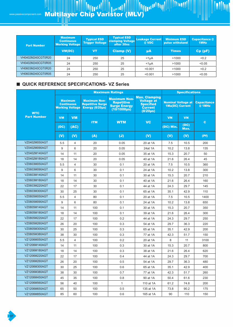
27
www.passivecomponent.com Multilayer Chip Varistor (MLV)
Part Number
Maximum Continuous
Working Voltage
Typical ESD Trigger Voltage
Typical ESD clamping Voltage
after 30ns
Leakage Current @ VDC
Minimum ESD pulse withstand
Capacitance @ 1MHz
VM(DC) VT Clamp (V) µA Times Cp (pF)
VH0402M240CGT0R20 24 250 25 <1μA >1000 <0.2VH0402M240CGT0R05 24 250 25 <1μA >1000 <0.05VH0603M240CGT0R20 24 250 25 <0.001 >1000 <0.2VH0603M240CGT0R05 24 250 25 <0.001 >1000 <0.05
■ QUICK REFERENCE SPECIFICATIONS- VZ Series
WTCPart Number
Maximum Ratings Specifications
Maximum Continuous
Working Voltage
Maximum Non-Repetitive Surge Energy (8/20µs)
Maximum Non-Repetitive
Surge Energy (10/1000µs)
Max. Clamping Voltage at Specified Current (8/20µs)
Nominal Voltage at 1Ma(DC) Current
Capacitance @ 1MHz
VM VMITM WTM VC
VN VN
C
(DC) (AC) (DC) Min.(DC) Max.
(V) (V) (A) (J) (V) (V) (V) (Pf)
VZ0402M050AGT 5.5 4 20 0.05 20�at�1A 7.5 10.5 200VZ0402M090AGT 9 6 20 0.05 24at�1A 10.2 13.8 135VZ0402M140AGT 14 11 20 0.05 35�at�1A 15.3 20.7 50VZ0402M180AGT 18 14 20 0.05 40�at�1A 21.6 26.4 45VZ0603M050AGT 5.5 4 30 0.1 20�at�1A 7.5 10.5 360VZ0603M090AGT 9 6 30 0.1 24�at�1A 10.2 13.8 300VZ0603M140AGT 14 11 30 0.1 30�at�1A 15.3 20.7 210VZ0603M180AGT 18 14 30 0.1 40�at�1A 21.6 26.4 160VZ0603M220AGT 22 17 30 0.1 44�at�1A 24.3 29.7 145VZ0603M300AGT 30 25 30 0.1 65�at�1A 35.1 42.9 110VZ0805M050AGT 5.5 4 80 0.1 20�at�1A 7.5 10.5 1400VZ0805M090AGT 9 6 80 0.1 24�at�1A 10.2 13.8 650VZ0805M140AGT 14 11 100 0.1 30�at�1A 15.3 20.7 350VZ0805M180AGT 18 14 100 0.1 39�at�1A 21.6 26.4 300VZ0805M220AGT 22 17 100 0.2 44�at�1A 24.3 29.7 250VZ0805M260AGT 26 20 100 0.3 54�at�1A 29.7 36.3 220VZ0805M300AGT 30 25 100 0.3 65�at�1A 35.1 42.9 200VZ0805M380AGT 38 30 100 0.3 77�at�1A 42.3 51.7 150VZ1206M050AGT 5.5 4 100 0.2 20�at�1A 8 11 3100VZ1206M140AGT 14 11 100 0.3 30�at�1A 15.3 20.7 800VZ1206M180AGT 18 14 100 0.3 38�at�1A 21.6 26.4 620VZ1206M220AGT 22 17 100 0.4 44�at�1A 24.3 29.7 700VZ1206M260AGT 26 20 100 0.5 54�at�1A 29.7 36.3 480VZ1206M300AGT 30 25 100 0.6 65�at�1A 35.1 42.9 400VZ1206M380AGT 38 30 100 0.7 77�at�1A 42.3 51.7 260VZ1206M450AGT 45 35 100 0.8 90�at�1A 50.4 61.6 230VZ1206M560AGT 56 40 100 1 110�at�1A 61.2 74.8 200
VZ1206M650AGT 65 50 100 0.5 135�at�1A 73.8 90.2 175
VZ1206M850AGT 85 60 100 0.6 165�at�1A 90 110 150

