metal injection anchors for use in masonry … · this etag applies to injection anchors consisting...
TRANSCRIPT
European Organisation for Technical Approvals Europäische Organisation für Technische Zulassungen Organisation Européenne pour l’Agrément Technique
Established pursuant to Annex II of the Council Directive 89/106 of 21 December 1988 on the approximation of laws, regulations and administrative provisions of Member States relating to construction products
(Construction Products Directive)
ETAG 029
GUIDELINE FOR EUROPEAN TECHNICAL APPROVAL
of
METAL INJECTION ANCHORS FOR USE IN MASONRY
Edition June 2010
This Guideline for European Technical Approval is established and published in accordance with Article 11 of the Construction Products Directive as a basis for the preparation and issue of European Technical Approvals in accordance with Article 9.1 of the Construction Products Directive.
European Technical Approvals are issued by Approval Bodies authorised and notified in accordance with Article 10 of the Construction Products Directive. These bodies are organized in EOTA.
The European Technical Approval, according to the Construction Products Directive, is a favourable technical assessment of the fitness for use of a construction product and the technical specification of the assessed product, serving as basis for the CE marking of this product when and where a harmonised standard according to the Directive is not or not yet available.
Due to technical innovation and the progress of the state of the art, Guidelines for technical approval might not reflect the latest developments and experiences gained in approval procedures. The reader of this Guideline is therefore advised to check with an EOTA member whether there are further provisions which have to be taken into account in the use of the Guideline.
Copy right: EOTA
Note: The copyright refers to the English reference version established by EOTA. For publications in accordance with Article 11.3 of the Construction Products Directive the national laws, regulations and administrative provisions of the Member State concerned are applicable.
__________________________________________________________________________________________________
EOTA Kunstlaan 40 Avenue des Arts B - 1040 BRUSSELS
ETAG 029
Introduction Notes Table of contents
1 Scope of the ETAG 3 1.1 Definition of the construction product 3 1.2 Intended use of the construction product 6 1.3 Assumed working life of the construction product 6 1.4 Terminology 6
1.4.1 Common terms relating to the Construction Products Directive 6 1.4.2 Specific terms used in this ETAG 7
1.5 Procedure in the case of a significant deviation from the ETAG 8
2 Assessment of fitness for use 9 2.1 Meaning of "fitness for use" 9 2.2 Elements of the assessment of fitness for use 9 2.3 Relationship of requirements to the product characteristics and
methods of verification and assessment 10 2.3.1 Relationship of requirements to the product characteristics 10 2.3.2 Use categories 11 2.4 Product characteristics which are relevant for the fitness for use
relating to Mechanical Resistance and Stability (ER1) 11 2.4.1 Method of verification /General) 11 2.4.2 Method of assessing and judging (General) 16
2.5 Verification method relating to Safety in Case of Fire (ER2) 22 2.6 Verification method relating to Hygiene, Health and the Environment (ER3) 23 2.7 Verification method relating to Durability 23
3 Evaluation and attestation of conformity and CE marking 26 3.1 System of attestation of conformity 26 3.2 Tasks and responsibilities of the manufacturer and notified bodies 27
3.2.1 Tasks of the manufacturer 27 3.2.2 Tasks of notified bodies 28
3.3 CE marking and accompanying information 28 3.4 Marking of the product 29
4 Assumptions under which the fitness for the intended use is assessed 29 4.1 Design method for anchorages 29 4.2 Packaging, transport, storage of the product 30 4.3 Installation of the product in the works 30
5 Identification of the construction product 31
6 Format of ETAs issued on the basis of the ETAG 33
7 Reference documents 33
Annex A Details of Tests
Annex B Recommendations for tests to be carried out on construction works
Annex C Design methods for anchorages
Addendum Format of ETAs issued on the basis of the ETAG
Page 2
ETAG 029
1 SCOPE OF THE ETAG The ETAG "METAL INJECTION ANCHORS FOR USE IN MASONRY“ covers the assessment of post-installed injection anchors placed into pre-drilled holes in masonry and anchored by bonding and mechanical interlock. The injection anchors are intended to be used for anchorages for which requirements for mechanical resistance and stability and safety in use in the sense of the Essential Requirements N° 1 (ER1) and N° 4 (ER4) of the CPD [1] shall be fulfilled; failure of anchorages made with these products would cause an immediate risk to human life and possible lead to considerable economic consequences. They are for fixing and/or supporting structural elements (which contribute to the stability of the works) or heavy units. The fixture can be supported either statically determinate (one or two supports) or statically indeterminate (more than two supports). The following annexes are full parts of the ETAG: Annex A: Details of tests Annex B: Recommendations for tests to be carried out on construction works (informative) Annex C: Design methods for anchorages 1.1. Definition of the construction product 1.1.1 Types and operating principles This ETAG applies to injection anchors consisting of a threaded rod, deformed reinforced bar, internal threaded socket, or other shapes and the mortar, placed into drilled holes in masonry and anchored by bonding the metal part to the sides of the drilled hole by means of mortar and by mechanical interlock (see Figure 1.1). For proper injection of the mortar, mesh sleeves made of metal or plastic are also covered in this ETAG (see Figure 1.2). Injection anchors are supplied and used as a unit. However if the metal parts are commercial standard parts supplied by another party than the approval holder (e.g. manufacturer of standard rods), the conditions according to 4.3 have to be fulfilled. 1.1.2 Materials This ETAG applies to anchors in which all the metal parts directly anchored in the masonry and designed to transmit the applied loads are made of either carbon steel, stainless steel or malleable cast iron. The bonding material may be manufactured from cementitious mortar (grout), synthetic mortar or a mixture of the two including fillers and/or additives. 1.1.3 Dimensions This ETAG applies to anchors with a minimum thread size of 6 mm (M6). The minimum anchorage depth of the anchor min hef shall be 50 mm. This ETAG applies to applications where the minimum thickness of the masonry members in which injection anchors are installed is at least h = 100 mm. Anchors with internal thread are covered only if they have a thread length of at least d + 5 mm after taking account of possible tolerances.
Page 3

ETAG 029
Figure 1.1 Example of injection anchors
Page 4

ETAG 029
Threaded anchor rod set in solid brick using injection mortar
Threaded anchor rod set in perforated brick using injection mortar and mesh sleeve
Threaded anchor rod set in hollow block using injection mortar and mesh sleeve
Figure 1.2 Example of injection anchors
Page 5

ETAG 029
1.1.4 Base material (masonry) This ETAG applies to the use of injection anchors in masonry units of clay, calcium silicate, normal weight concrete, lightweight aggregate concrete (solid and hollow format blocks), autoclaved aerated concrete or other similar materials. As far as the specification of the different masonry units is concerned, EN 771-1 to 5:2003+A1:2005 [2] may be taken as reference. The design and construction of masonry structures in which the injection anchors are to be anchored shall be in accordance with EN 1996-1-1:2005 [6] and the relevant national regulations. Attention is drawn to the fact that the standards for masonry are not very restrictive with regard to details of units (e.g. type, dimensions and location of hollows, number and thickness of webs). Anchor resistance and load displacement behaviour, however, decisively depend on these influencing factors. Usually solid masonry units do not have any holes or cavities other than those inherent in the material. However, solid units may have a vertical perforation of up to 15% of the cross section. Therefore testing in solid material cover units with vertical perforation of up to 15% cross section is also required. Masonry units consisting of hollow or perforated units have a certain volume percentage of voids which pass through the masonry unit. For the assessment of injection anchors anchored in hollow or perforated units it has also to be assumed that the anchor may be situated in solid material (e.g. joints, solid part of unit without holes) so that also tests in solid material may be required. 1.2 Intended use of the construction product The injection anchors are intended to be used for anchorages for which requirements for mechanical resistance and stability and safety in use in the sense of the Essential Requirements N° 1 (ER1) and N° 4 (ER4) of the CPD shall be fulfilled; failure of anchorages made with these products would cause an immediate risk to human life and possible lead to considerable economic consequences. They are for fixing and/or supporting structural elements (which contribute to the stability of the works) or heavy units. This ETAG applies to anchors subject to static or quasi-static actions in tension, shear or combined tension and shear or bending; it is not applicable to anchors loaded in compression or subject to fatigue, impact, or seismic actions. This ETAG covers applications only where the masonry members in which the anchors are embedded are subject to static or quasi-static actions. 1.3 Assumed working life of the construction product The provisions and the verification and assessment methods included or referred to in this ETAG have been written based upon the assumed working life of the injection anchors for the intended use of 50 years when installed in the works, provided that the injection anchors is subject to appropriate installation and use (see 4.3). These provisions are based upon the current state of the art and the available knowledge and experience. "Assumed working life" means that, when an assessment following the ETAG provisions is made, and when this working life has elapsed, the real working life may be, in normal use conditions, considerably longer without major degradation affecting the Essential Requirements. The indications of durability (linked to the working life) of the construction product cannot be interpreted as a guarantee given by the product manufacturer or his representative or the Approval Body issuing the ETA, but are regarded only as a means for choosing the appropriate products in relation to the expected economically reasonable working life of the works (see 5.2.2 of the Interpretative Documents). 1.4 Terminology 1.4.1 Common terms relating to the Construction Products Directive For the meaning of these terms see EOTA document "Common terms used in Guidelines for European Technical Approval" published on the EOTA website.
Page 6

ETAG 029
1.4.2 Specific terms used in this ETAG 1.4.2.1 General Anchor = a manufactured, assembled component including bonding materials for achieving anchorage between the base material (masonry) and the fixture. Anchor group = several anchors (working together) Fixture = component to be fixed to the masonry Anchorage = an assembly comprising base material (masonry), anchor or anchor group and component fixed to the masonry. 1.4.2.2 Anchors The notations and symbols frequently used in this Guideline are given below. Further particular notation and symbols are given in the text. b = width of the member of the base material c = edge distance ccr,N = edge distance for ensuring the transmission of the characteristic tensile resistance of a single injection anchor cmin = minimum allowable edge distance d = anchor bolt/thread diameter do = drill hole diameter dcut = cutting diameter of drill bit dcut,m = medium cutting diameter of drill bit df = diameter of clearance hole in the fixture dnom = outside diameter of anchor h = thickness of masonry member (wall) hmin = minimum thickness of masonry member ho = depth of cylindrical drill hole at shoulder h1 = depth of drilled hole to deepest point hef = effective anchorage depth hnom = overall anchor embedment depth in the masonry lunit = length of the masonry unit s = spacing of the injection anchor scr,N = spacing for ensuring the transmission of the characteristic resistance of a single injection anchor smin = minimum allowable spacing scr,test = spacing of a group of anchors in the relevant test T = torque moment Tinst = installation torque moment recommended by the manufacturer Tu = maximum torque moment during failure tfix = thickness of fixture t = thickness of outer web of the brick 1.4.2.3 Base materials (masonry) and metal parts of anchor ρ = bulk density of masonry unit fb = normalised mean compression strength of masonry unit fb,test = mean compression strength of the test masonry unit at the time of testing fy,test = steel tensile yield strength in the test fyk = nominal characteristic steel yield strength fu,test = steel ultimate tensile strength in the test fuk = nominal characteristic steel ultimate strength 1.4.2.4 Loads/forces F = force in general N = normal force (+N = tension force) V = shear force M = moment NRk,VRk = characteristic anchor resistance (5 %-fractile of results) under tension or shear force respectively
hSdN ( ) = design value of tensile load (shear load) acting on the most stressed anchor of an h
SdV anchor group
Page 7
ETAG 029
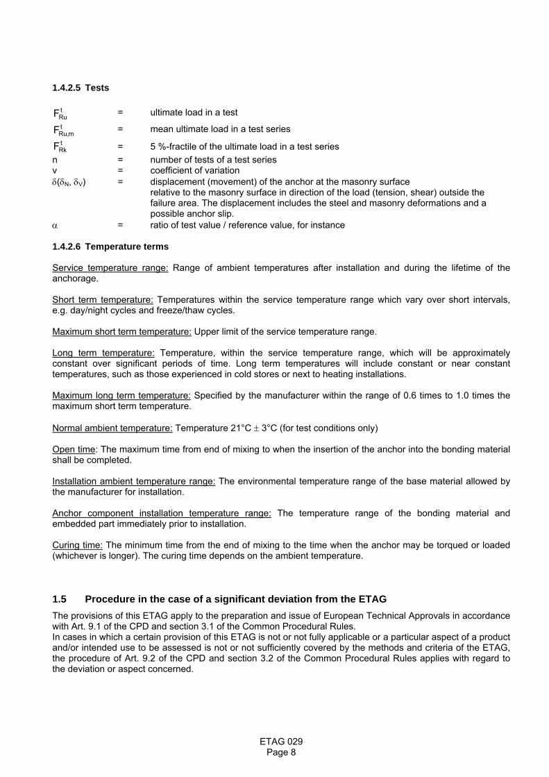
1.4.2.5 Tests
tRuF = ultimate load in a test t
mRu,F = mean ultimate load in a test series tRkF = 5 %-fractile of the ultimate load in a test series
n = number of tests of a test series v = coefficient of variation δ(δN, δV) = displacement (movement) of the anchor at the masonry surface relative to the masonry surface in direction of the load (tension, shear) outside the
failure area. The displacement includes the steel and masonry deformations and a possible anchor slip.
α = ratio of test value / reference value, for instance 1.4.2.6 Temperature terms Service temperature range: Range of ambient temperatures after installation and during the lifetime of the anchorage. Short term temperature: Temperatures within the service temperature range which vary over short intervals, e.g. day/night cycles and freeze/thaw cycles. Maximum short term temperature: Upper limit of the service temperature range. Long term temperature: Temperature, within the service temperature range, which will be approximately constant over significant periods of time. Long term temperatures will include constant or near constant temperatures, such as those experienced in cold stores or next to heating installations. Maximum long term temperature: Specified by the manufacturer within the range of 0.6 times to 1.0 times the maximum short term temperature. Normal ambient temperature: Temperature 21°C ± 3°C (for test conditions only) Open time: The maximum time from end of mixing to when the insertion of the anchor into the bonding material shall be completed. Installation ambient temperature range: The environmental temperature range of the base material allowed by the manufacturer for installation. Anchor component installation temperature range: The temperature range of the bonding material and embedded part immediately prior to installation. Curing time: The minimum time from the end of mixing to the time when the anchor may be torqued or loaded (whichever is longer). The curing time depends on the ambient temperature. 1.5 Procedure in the case of a significant deviation from the ETAG The provisions of this ETAG apply to the preparation and issue of European Technical Approvals in accordance with Art. 9.1 of the CPD and section 3.1 of the Common Procedural Rules. In cases in which a certain provision of this ETAG is not or not fully applicable or a particular aspect of a product and/or intended use to be assessed is not or not sufficiently covered by the methods and criteria of the ETAG, the procedure of Art. 9.2 of the CPD and section 3.2 of the Common Procedural Rules applies with regard to the deviation or aspect concerned.
Page 8

ETAG 029
2 ASSESSMENT OF FITNESS FOR USE 2.1 Meaning of "fitness for use" "Fitness for (the intended) use" of a construction product means that the product has such characteristics that
the works in which it is to be incorporated can, if properly designed and built,
1. satisfy the Essential Requirements when and where such works are subject to regulations containing such requirements (CPD Art. 2.1) and
2. be fit for their intended use, account being taken of economy, and in this connection satisfy the Essential Requirements for an economically reasonable working life, if normally maintained (see CPD Annex I, sentence 1 and 2).
2.2 Elements of the assessment of fitness for use The assessment of the fitness of a construction product for its intended use includes:
the identification of the characteristics of the product which are relevant to its fitness for use (in the following referred to as "regulatory characteristics");
the establishment of methods for the verification and assessment of the regulatory product characteristics and the expression of the respective product performances;
the identification of such regulatory characteristics to which the option "No Performance Determined" applies for the reason that in one or more Member States they are not relevant for the fulfilment of the requirements applicable to the works;
the identification of such regulatory characteristics for which limit values (threshold values) have to be respected for technical reasons.
Page 9
ETAG 029
2.3 Relationship of requirements to the product characteristics and methods of verification and assessment
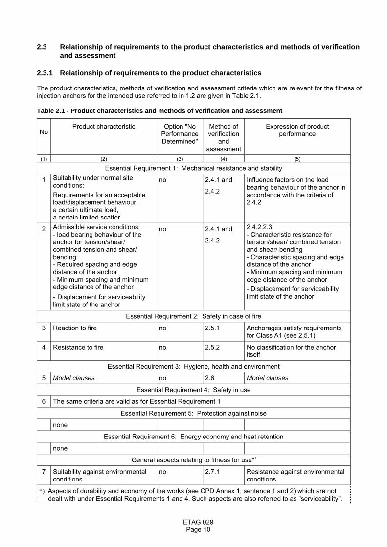
2.3.1 Relationship of requirements to the product characteristics The product characteristics, methods of verification and assessment criteria which are relevant for the fitness of injection anchors for the intended use referred to in 1.2 are given in Table 2.1. Table 2.1 - Product characteristics and methods of verification and assessment
No
Product characteristic
Option "No Performance Determined"
Method of verification
and assessment
Expression of product performance
(1) (2) (3) (4) (5)
Essential Requirement 1: Mechanical resistance and stability
1 Suitability under normal site conditions: Requirements for an acceptable load/displacement behaviour, a certain ultimate load, a certain limited scatter
no 2.4.1 and
2.4.2
Influence factors on the load bearing behaviour of the anchor in accordance with the criteria of 2.4.2
2 Admissible service conditions: - load bearing behaviour of the anchor for tension/shear/ combined tension and shear/ bending - Required spacing and edge distance of the anchor - Minimum spacing and minimum edge distance of the anchor - Displacement for serviceability limit state of the anchor
no 2.4.1 and
2.4.2
2.4.2.2.3 - Characteristic resistance for tension/shear/ combined tension and shear/ bending - Characteristic spacing and edge distance of the anchor - Minimum spacing and minimum edge distance of the anchor - Displacement for serviceability limit state of the anchor
Essential Requirement 2: Safety in case of fire
3 Reaction to fire no 2.5.1 Anchorages satisfy requirements for Class A1 (see 2.5.1)
4 Resistance to fire no 2.5.2 No classification for the anchor itself
Essential Requirement 3: Hygiene, health and environment
5 Model clauses no 2.6 Model clauses
Essential Requirement 4: Safety in use
6 The same criteria are valid as for Essential Requirement 1
Essential Requirement 5: Protection against noise
none
Essential Requirement 6: Energy economy and heat retention
none
General aspects relating to fitness for use*)
7 Suitability against environmental conditions
no 2.7.1 Resistance against environmental conditions
*) Aspects of durability and economy of the works (see CPD Annex 1, sentence 1 and 2) which are not dealt with under Essential Requirements 1 and 4. Such aspects are also referred to as "serviceability".
Page 10

ETAG 029
2.3.2 Use categories The Guideline applies to anchorages in respect to the following use categories: 2.3.2.1 Use categories in respect of the base material: Use category b: Metal injection anchors for use in solid1) masonry Use category c: Metal injection anchors for use in hollow or perforated masonry Use category d : Metal injection anchors for use in autoclaved aerated concrete masonry Use category c covers also use category b 1) covers also units with vertically perforation of up to 15% cross section 2.3.2.2 Use categories in respect of installation and use: Category d/d- Installation and use in structures subject to dry, internal conditions, Category w/d- Installation in wet substrate and use in structures subject to dry, internal conditions, Category w/w- Installation and use in structures subject to other environmental conditions (e.g. wet). Use category w/w covers also use category w/d. 2.3.2.3 Use categories in respect to the service temperature range: The functioning of an injection anchor, including its ability to continue to withstand its design load with an appropriate safety factor and to limit displacements, shall not be adversely affected by temperatures in the base material near to the surface within a temperature range to be specified by the manufacturer which may be either: (Ta) - 40°C to + 40°C (max short term temperature + 40°C and max long term temperature + 24°C) (Tb) - 40°C to + 80°C (max short term temperature + 80°C and max long term temperature + 50°C) (Tc) on manufacturer's request with –40°C to T1 (short term: T1>+40°C, long term:0.6 T1 to 1.0 T1) Injection anchors are not affected by service temperatures down to - 40°C. If there is no experience for unknown bonding materials on their performance at - 40°C then normal pull-out tests at - 40°C will be required. The performance shall not be adversely affected by short term temperatures within the service temperature range or by long term temperatures up to the maximum long term temperature. Performance at the maximum long term temperature and maximum short term temperature is checked by tests described in 2.4.1.1.2 2.4 Product characteristics which are relevant for the fitness for use
relating to Mechanical Resistance and Stability (ER 1) 2.4.1 Method of verification (General) The tests involved in the assessment of injection anchors fall into 3 categories: (1) Tests for confirming their suitability (see 2.4.1.1) (2) Tests for evaluating the admissible service conditions (see 2.4.1.2) (3) Tests for checking durability (see 2.7.1) The details of tests are given in Annex A. It is assumed that for each injection anchor size there is only one anchorage depth. If the injection anchors are intended to be installed with two anchorage depths the tests have to be carried out at both depths. 2.4.1.1 Tests for suitability The purpose of the suitability tests is to establish whether an anchor is capable of safe, effective behaviour in service including consideration of adverse conditions both during site installation and in service. The types of suitability tests, test conditions, the number of required tests and the criteria applied to the results shall be taken in accordance with Table 2.4.1. Detailed information about special tests are given in the chapters after the Table.
Page 11
ETAG 029
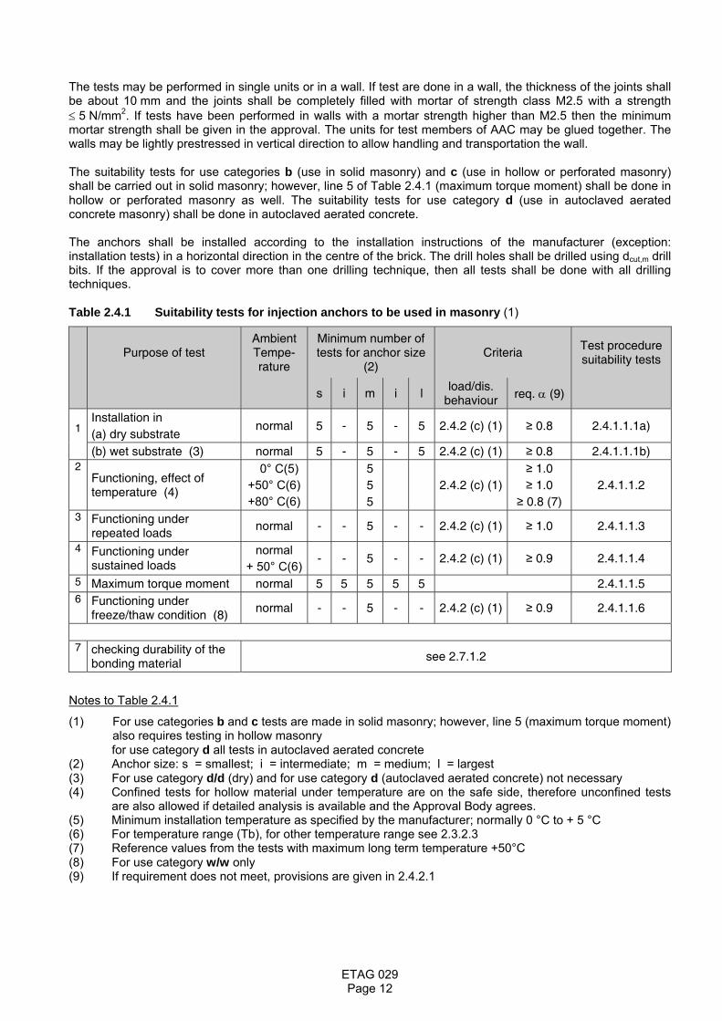
The tests may be performed in single units or in a wall. If test are done in a wall, the thickness of the joints shall be about 10 mm and the joints shall be completely filled with mortar of strength class M2.5 with a strength ≤ 5 N/mm2. If tests have been performed in walls with a mortar strength higher than M2.5 then the minimum mortar strength shall be given in the approval. The units for test members of AAC may be glued together. The walls may be lightly prestressed in vertical direction to allow handling and transportation the wall. The suitability tests for use categories b (use in solid masonry) and c (use in hollow or perforated masonry) shall be carried out in solid masonry; however, line 5 of Table 2.4.1 (maximum torque moment) shall be done in hollow or perforated masonry as well. The suitability tests for use category d (use in autoclaved aerated concrete masonry) shall be done in autoclaved aerated concrete. The anchors shall be installed according to the installation instructions of the manufacturer (exception: installation tests) in a horizontal direction in the centre of the brick. The drill holes shall be drilled using dcut,m drill bits. If the approval is to cover more than one drilling technique, then all tests shall be done with all drilling techniques. Table 2.4.1 Suitability tests for injection anchors to be used in masonry (1)
Purpose of test
Ambient Tempe-rature
Minimum number of tests for anchor size
(2) Criteria
Test procedure suitability tests
s i m i l
load/dis. behaviour req. α (9)
1
Installation in (a) dry substrate
normal 5 - 5 - 5 2.4.2 (c) (1) ≥ 0.8 2.4.1.1.1a)
(b) wet substrate (3) normal 5 - 5 - 5 2.4.2 (c) (1) ≥ 0.8 2.4.1.1.1b) 2
Functioning, effect of temperature (4)
0° C(5) +50° C(6) +80° C(6)
5 5 5
2.4.2 (c) (1) ≥ 1.0 ≥ 1.0
≥ 0.8 (7) 2.4.1.1.2
3 Functioning under repeated loads
normal - - 5 - - 2.4.2 (c) (1) ≥ 1.0 2.4.1.1.3
4 Functioning under sustained loads
normal + 50° C(6)
- - 5 - - 2.4.2 (c) (1) ≥ 0.9 2.4.1.1.4
5 Maximum torque moment normal 5 5 5 5 5 2.4.1.1.5 6 Functioning under
freeze/thaw condition (8) normal - - 5 - - 2.4.2 (c) (1) ≥ 0.9 2.4.1.1.6
7 checking durability of the
bonding material see 2.7.1.2
Notes to Table 2.4.1
(1) For use categories b and c tests are made in solid masonry; however, line 5 (maximum torque moment) also requires testing in hollow masonry for use category d all tests in autoclaved aerated concrete
(2) Anchor size: s = smallest; i = intermediate; m = medium; l = largest (3) For use category d/d (dry) and for use category d (autoclaved aerated concrete) not necessary (4) Confined tests for hollow material under temperature are on the safe side, therefore unconfined tests
are also allowed if detailed analysis is available and the Approval Body agrees. (5) Minimum installation temperature as specified by the manufacturer; normally 0 °C to + 5 °C (6) For temperature range (Tb), for other temperature range see 2.3.2.3 (7) Reference values from the tests with maximum long term temperature +50°C (8) For use category w/w only (9) If requirement does not meet, provisions are given in 2.4.2.1
Page 12

ETAG 029
2.4.1.1.1 Installation in dry or wet substrate (a) Installation in dry substrate; these tests have to be done for all use categories Confined tension tests in dry solid masonry according to Annex A, A.5.4 a). (b) Installation in wet substrate; for use category d/d (dry) and for use category d (autoclaved aerated concrete) not necessary Confined tension tests in wet solid masonry according to Annex A, A.5.4 b). 2.4.1.1.2 Influence of temperature on characteristic resistances a) Effect of increased temperature The confined tension tests shall be carried out according to Annex A, A.5.5 a) for the different temperature ranges given in 2.3.2.3. b) Effect of low installation temperature The confined tension tests shall be carried out at the end of the curing time while maintaining the temperature of the test member at the specified lowest installation temperature ± 2K. Details of the tests are described in Annex A, A.5.5 b). c) Minimum curing time at normal ambient temperature Perform tension tests according to Annex A, A.5.5 c) at normal ambient temperature at the corresponding minimum curing time specified by the manufacturer. 2.4.1.1.3 Repeated loading The injection anchor is subjected to 1 x 10⁵ load cycles with a maximum frequency of approximately 6 Hz. After completion of the load cycles the anchor shall be unloaded, the displacement measured and a tension test performed according to Annex A. Details of the tests are described in Annex A, 5.6. 2.4.1.1.4 Sustained loading The test is performed at normal temperature (T= + 21°C) for temperature range (Ta), (Tb) and (Tc) and at maximum steady temperature for temperature range (Tb) and (Tc) [T= + 50°C for temperature range b)]. The anchor shall be installed at normal temperature subjected to a tension (sustained) load. After completion of the sustained load test the anchor shall be unloaded, the displacement measured and immediately after unloading a tension test performed. Details of the tests are described in Annex A, A.5.7. 2.4.1.1.5 Maximum torque moment The torque moment shall be measured with a calibrated torque moment transducer. The torque moment shall be increased until failure of the injection anchor. Details of the tests are described in Annex A, A.5.8. 2.4.1.1.6 Functioning under freeze/thaw conditions In general the tests are carried out for injection anchors with a service condition in wet substrate only. The tests are performed in freeze-thaw resistant base material. The tests may also be carried out in freeze-thaw resistant concrete C50/60; in this case the corresponding reference tests are required in concrete under normal conditions as well. The displacements shall be measured during the temperature cycles. After completion of 50 cycles carry out a tension test at normal ambient temperature. Details of the tests are described in Annex A, A.5.9.
Page 13

ETAG 029
2.4.1.2 Tests for evaluating the admissible service conditions The tests may be performed in single units or in a wall. If test are done in a wall, the thickness of the joints shall be about 10 mm and the joints shall be completely filled with mortar of strength class M2.5 with a strength ≤ 5 N/mm2. If tests have been performed in walls with a mortar strength higher than M2.5 then the minimum mortar strength shall be given in the approval. The units for test members of AAC may be glued together. The walls may be lightly prestressed in vertical direction to allow handling and transportation. For determination of the admissible service conditions, the tests given in Table 2.4.2 shall be carried out. If existing information is available from the manufacturer and the corresponding test report contains all relevant data, then the Approval Body may reduce the number of tests for admissible service conditions, making use of this existing information. However, it will be considered in the assessment only if the results are consistent with the test results of the Approval Body. All tests for determination of admissible service conditions shall be carried out according to Annex A in the base material for which the injection anchor is intended to be used at normal ambient temperature (+21°C ± 3°C). The drill holes shall be drilled using dcut,m drill bits. The minimum edge distance cmin and minimum spacing smin shall be given by the manufacturer and shall be confirmed by the corresponding tests. The determined characteristic resistances for the approval are valid only for the bricks and blocks which are used in the tests regarding base material (masonry or aerated concrete), size of units, compressive strength and configuration of the voids. Therefore the following information has to be given in the test report and in the approval: Base material, size of units, normalised compressive strength; volume of all holes (% of the gross volume); volume of any hole (% of the gross volume); minimum thickness in and around holes (web and shell); combined thickness of webs and shells (% of the overall width); appropriation to a group of Table 3.1 of EC 06 [6]. As far as the specification of the different masonry units is concerned, EN 771-1 to 5:2003 +A1:2005 [2] may be taken as reference. The characteristic resistance of the anchor may be determined by "job site tests" according to Annex B, if the anchor has an approval with characteristic values for the same base material as it is present on the construction works. Furthermore job site tests for use in solid masonry are possible only if the injection anchor has an approval for use in solid masonry and job site tests for use in hollow or perforated masonry are possible only if the injection anchor has an approval for use in hollow or perforated masonry.
Page 14

ETAG 029
Table 2.4.2 Tests for admissible service conditions for injection anchors for use in masonry
1 3 4 5 6 7 8
Purpose of test Load direc-tion
Distances Member thickness
h Remarks Number of
tests (2)
Test procedure described in
Annex A s m l
1 Reference tension tests for suitability tests (1) N
s > scr,N c > ccr,N
≥ hmin test with single
anchors 5 5 5 Annex A, A.5.1
2 Characteristic resistance for tension loading not influenced by edge and spacing effects (2)
N s > scr,N (4)
c > ccr,N ≥ hmin
test with single
anchors 5 5 5 Annex A, A.5.2
3 Characteristic resistance for shear loading not influenced by edge and spacing effects (2)
V s > scr,N c > ccr,N
≥ hmin test with single
anchors 5 5 5 Annex A, A.5.3
4 Minimum edge distance for characteristic tension resistance(3)
N s > smin c = cmin
= hmin test with single
anchors 5 5 5 Annex A
Notes to Table 2.4.2
(1) Reference tension tests for determination of the results of the suitability tests. They have to be carried out on the same masonry units regarding base material, size of units and compressive strength as used for the corresponding suitability tests. The results of reference tests may also be considered for evaluating the characteristic resistance of the anchors.
(2) The tests shall be carried out at the most unfavourable setting position in the brick of hollow or perforated masonry, which give the lowest characteristic resistance of the anchor
(3) Tension tests with single anchors near the free edge of a wall to determine the characteristic resistance depending on the minimum edge distance cmin
This test may be omitted if the minimum edge distances and spacing are greater than the following values:
smin = cmin = ≥ 50mm ≥ 3 do for solid material
smin = cmin = ≥ 100mm ≥ 6 do for hollow material
(4) For determination of a group of two or four injection anchors the following spacing may be used: for anchorages in solid masonry and AAC: scr,N = 20d for anchorages in hollow or perforated masonry: scr,N = lunit
lunit = given in the approval (length of masonry unit in the tests)
The spacing scr,N may also be evaluated by appropriate tests with a anchor group of two anchors with scr,test
scr,N = shall be given in the approval (spacing of a group of anchors in the tests)
Page 15
ETAG 029
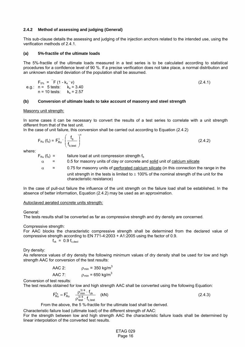
2.4.2 Method of assessing and judging (General) This sub-clause details the assessing and judging of the injection anchors related to the intended use, using the verification methods of 2.4.1. (a) 5%-fractile of the ultimate loads The 5%-fractile of the ultimate loads measured in a test series is to be calculated according to statistical procedures for a confidence level of 90 %. If a precise verification does not take place, a normal distribution and an unknown standard deviation of the population shall be assumed. F5% = ⎯F (1 - ks . v) (2.4.1) e.g.: n = 5 tests: ks = 3.40 n = 10 tests: ks = 2.57 (b) Conversion of ultimate loads to take account of masonry and steel strength Masonry unit strength: In some cases it can be necessary to convert the results of a test series to correlate with a unit strength different from that of the test unit. In the case of unit failure, this conversion shall be carried out according to Equation (2.4.2)
FRu (fb) = . tRuF
α
⎟⎟⎠
⎞⎜⎜⎝
⎛
test,b
b
ff
(2.4.2)
where: FRu (fb) = failure load at unit compression strength fb α = 0.5 for masonry units of clay or concrete and solid unit of calcium silicate α = 0.75 for masonry units of perforated calcium silicate (in this connection the range in the
unit strength in the tests is limited to ± 100% of the nominal strength of the unit for the characteristic resistance)
In the case of pull-out failure the influence of the unit strength on the failure load shall be established. In the absence of better information, Equation (2.4.2) may be used as an approximation. Autoclaved aerated concrete units strength: General: The tests results shall be converted as far as compressive strength and dry density are concerned. Compressive strength: For AAC blocks the characteristic compressive strength shall be determined from the declared value of compressive strength according to EN 771-4:2003 + A1:2005 using the factor of 0.9. fck = 0.9 fc,decl Dry density: As reference values of dry density the following minimum values of dry density shall be used for low and high strength AAC for conversion of the test results:
AAC 2: ρmin = 350 kg/m3 AAC 7: ρmin = 650 kg/m3
Conversion of test results: The test results obtained for low and high strength AAC shall be converted using the following Equation:
test,c
4/3test
ck4/3
mintRu
tRu f
fFF K
⋅ρ⋅ρ
= (kN) (2.4.3)
From the above, the 5 %-fractile for the ultimate load shall be derived. Characteristic failure load (ultimate load) of the different strength of AAC: For the strength between low and high strength AAC the characteristic failure loads shall be determined by linear interpolation of the converted test results.
Page 16

ETAG 029
Steel strength: In case of steel failure the failure load shall be converted to the nominal steel strength by Equation (2.4.4)
FRu (fuk) = . tRuF
u,test
uk
ff
(2.4.4)
where: FRu (fuk) = failure load at nominal steel ultimate strength (c) In all tests the following criteria shall be met: (1) The load-displacement curves shall show a steady increase (see Figure 2.4); uncontrolled slip of injection
anchors is not allowed.
Uncontrolled slip occurs when the mortar with the embedded part is pulled out of the drilled hole (because then the load displacement behaviour depends significantly on irregularities of the drilled hole). The corresponding load when uncontrolled slip starts is called load at loss of adhesion Nu,adh. For the requirement on the load-displacement curves with respect to uncontrolled slip the following evaluation shall be done:
Nu,adh shall be evaluated for every test from the measured load displacement curve. In general the load at
loss of adhesion is characterised by a significant change of stiffness, see Figure 2.4 a. If the change in stiffness at a defined load is not so obvious e.g. the stiffness is smoothly decreasing, than the load at loss of adhesion shall be evaluated as follows:
1) Compute the tangent to the load-displacement curve at a load 0.3 Nu (Nu = peak load in test). In general the tangent stiffness can be taken as the secant stiffness between the points 0/0 and 0.3 Nu/δ0,3 (δ0,3 = displacement at N = 0.3 Nu).
2) Divide the tangent stiffness by a factor of 1.5. 3) Draw a line through the point 0/0 with the stiffness as calculated in 2). 4) The point of intersection between this line and the measured load-displacement curve gives the load
Nu,adh where the adhesion fails, see Figure 2.4 b. If there is a peak in the load-displacement curve to the left side of this line which is higher than the load at
intersection then Nu,adh is taken as the peak load, see Figure 2.4 c. If there is a very stiff load-displacement curve at the beginning (δ0,3 ≤ 0.05mm) then the drawing of the line
for the calculation can be shifted to the point (0.3 Nu/δ0,3 ), see Figure 2.4 d. For all tests, the factor α1 shall be calculated according to Equation (2.4.5):
α1 = 4
M
pRk,
adhu,
NN
γγ⋅ (2.4.5)
Nu,adh = load at loss of adhesion as defined above NRk,p = characteristic resistance for pullout failure given in the approval γ4 = 1.3 γM = partial safety factor given in the approval The minimum value of α1 of all tests is decisive. If the value of α1 is less than 1.0 then the characteristic resistance NRk,p shall be reduced according to 2.4.2.2.3. The evaluation of the load at loss of adhesion is not required when failure occurs between mortar and embedded part along the entire embedment depth (see definition of uncontrolled slip). In this case the factor α1 may be taken as 1.0.
Page 17

ETAG 029 Page 18
a) load at loss of adhesion by a significant change of stiffness b) evaluation of load at loss of adhesion
c) evaluation of load at loss of adhesion d) evaluation of load at loss of adhesion
Figure 2.4 Examples of load-displacement curves
(2) In general, in each test series, the coefficient of variation of the ultimate load shall be smaller than
v = 30 % in the suitability tests and v = 20 % in the admissible service condition tests. If the coefficient of variation of the ultimate load in the suitability test is greater than 30%, then the following αV-value has to be taken into account:
αV = [ ] )30%v(03.011
−⋅+ ≤ 1.0 (2.4.6)
If the coefficient of variation of the ultimate load in the admissible service condition test is greater than 20%, then the following αV-value has to be taken into account:
αV = [ ] )20%v(03.011
−⋅+ ≤ 1.0 (2.4.7)
ETAG 029
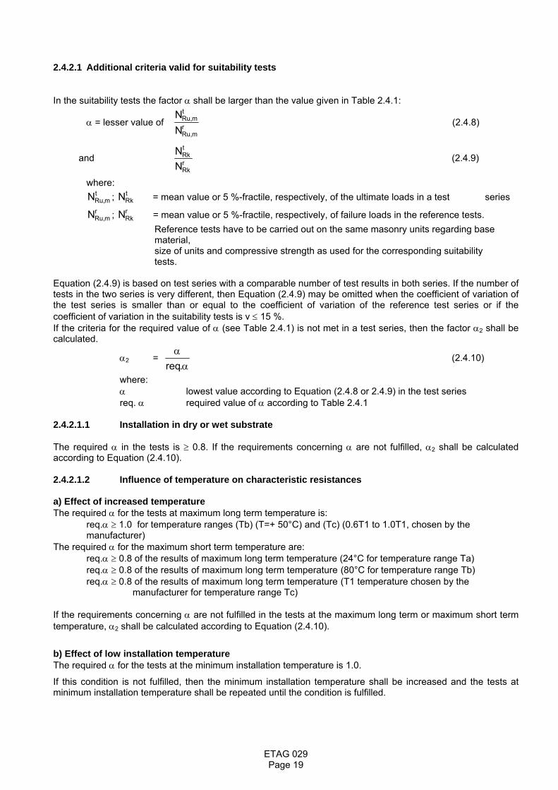
2.4.2.1 Additional criteria valid for suitability tests In the suitability tests the factor α shall be larger than the value given in Table 2.4.1:
α = lesser value of rmRu,
tmRu,
NN
(2.4.8)
and rRk
tRk
NN
(2.4.9)
where: ; = mean value or 5 %-fractile, respectively, of the ultimate loads in a test series t
mRu,N tRkN
; = mean value or 5 %-fractile, respectively, of failure loads in the reference tests. rmRu,N r
RkN Reference tests have to be carried out on the same masonry units regarding base
material, size of units and compressive strength as used for the corresponding suitability tests. Equation (2.4.9) is based on test series with a comparable number of test results in both series. If the number of tests in the two series is very different, then Equation (2.4.9) may be omitted when the coefficient of variation of the test series is smaller than or equal to the coefficient of variation of the reference test series or if the coefficient of variation in the suitability tests is v ≤ 15 %. If the criteria for the required value of α (see Table 2.4.1) is not met in a test series, then the factor α2 shall be calculated.
α2 = α
α.req
(2.4.10)
where: α lowest value according to Equation (2.4.8 or 2.4.9) in the test series req. α required value of α according to Table 2.4.1 2.4.2.1.1 Installation in dry or wet substrate The required α in the tests is ≥ 0.8. If the requirements concerning α are not fulfilled, α2 shall be calculated according to Equation (2.4.10). 2.4.2.1.2 Influence of temperature on characteristic resistances a) Effect of increased temperature The required α for the tests at maximum long term temperature is:
req.α ≥ 1.0 for temperature ranges (Tb) (T=+ 50°C) and (Tc) (0.6T1 to 1.0T1, chosen by the manufacturer)
The required α for the maximum short term temperature are: req.α ≥ 0.8 of the results of maximum long term temperature (24°C for temperature range Ta) req.α ≥ 0.8 of the results of maximum long term temperature (80°C for temperature range Tb) req.α ≥ 0.8 of the results of maximum long term temperature (T1 temperature chosen by the manufacturer for temperature range Tc) If the requirements concerning α are not fulfilled in the tests at the maximum long term or maximum short term temperature, α2 shall be calculated according to Equation (2.4.10).
b) Effect of low installation temperature The required α for the tests at the minimum installation temperature is 1.0.
If this condition is not fulfilled, then the minimum installation temperature shall be increased and the tests at minimum installation temperature shall be repeated until the condition is fulfilled.
Page 19
ETAG 029
c) Minimum curing time at normal ambient temperature The mean failure loads and the 5% fractile of failure loads measured in tests at the normal ambient temperature and corresponding minimum curing time shall be at least 0.9 times to the values measured in reference tests with a "long curing time" in the tests for admissible service conditions. The "long curing time" is the maximum curing time normally used in admissible service condition tests (24 hours for resins, 14 days for cementitious mortars).
If this condition is not fulfilled, then the minimum curing time at normal ambient temperature shall be increased and the corresponding tests shall be repeated or the characteristic resistance for pull-out failure given in the ETA is reduced according to Equation 2.4.10. 2.4.2.1.3 Repeating loading The increase of displacements during cycling shall stabilise in a manner indicating that failure is unlikely to occur after some additional cycles. This condition may be assumed as fulfilled if the displacements after cycling at max N of the test are smaller than the mean value of the displacements overcoming the friction resistance in the reference tests. If the above condition on the displacement is not fulfilled, the tests have to be repeated with a lower maximum load (max N) until this condition is fulfilled. Then the characteristic resistance NRk shall be reduced by the factor max N (applied) / max N (required). The required α for the pull-out tests subsequent to the cycling loading is 1.0. If this condition is not fulfilled, α2 shall be calculated according to Equation (2.4.10). 2.4.2.1.4 Sustained loading The displacements measured in the tests have to be extrapolated according to Equation (2.4.11) (Findley approach) to 50 years (tests at normal ambient temperature), or 10 years (tests at maximum long term temperature), respectively. The curve fitting shall start with the displacement measured after approximately 100 h. s(t) = so + a · tb (2.4.11) so = initial displacement under the sustained load at t = 0 (measured directly after applying the sustained load) a, b = constants (tuning factors), evaluated by a regression analysis of the deformations measured during the sustained load tests The extrapolated displacements shall be less than the mean value of the displacements at the load at overcoming the friction resistance in the reference tests. If this condition is not fulfilled, the tests have to be repeated with a lower load Np until the requirement is fulfilled and the characteristic resistance shall be reduced by the factor Np (applied) / Np (required). The failure loads measured in the pull-out tests subsequent to the sustained loading shall be compared with the failure loads measured in the reference tests (sustained load tests at normal temperature) or in the suitability tests at maximum long term temperature (sustained load tests at maximum long term temperature). The required α is 0.9. If this condition is not fulfilled, α2 shall be calculated according to Equation (2.4.10). 2.4.2.1.5 Maximum torque moment The installation of the injection anchor shall be practicable without steel failure, turn-through in the hole or failure of the anchorage. This condition may be assumed to be fulfilled if the following conditions are met. The ratio of the maximum torque moment Tu during failure to the installation moment Tinst recommended by the manufacturer shall be determined for every test. The 5%-fractile of the ratio for all tests shall be at least 2.1. The conversion to the nominal masonry strength may be omitted for these determinations. 2.4.2.1.6 Functioning under freeze/thaw conditions The rate of displacement increase shall be reduced with increasing number of freeze/thaw cycles to a value almost equal to zero.
Page 20

ETAG 029
2.4.2.2 Criteria for admissible service conditions tests 2.4.2.2.1 General In all tension tests, the requirement for the load/displacement curves shall satisfy the requirements laid down in 2.4.2 c (1). The requirements on the coefficient of variation of the ultimate loads are given in 2.4.2 c (2). 2.4.2.2.2 Characteristic resistance of a single anchor for the different conditions The characteristic resistances of the injection anchor for the different failure modes under tension and shear loading shall be evaluated by the corresponding tests to get the required values for the design method according to Annex C.
2.4.2.2.3 Characteristic resistance of a single anchor in the ETA The characteristic resistances of single anchors without edge and spacing effects under tension loading shall be calculated as follows: NRk = NRk,0 ⋅ min1) (min α1 ; min α2, line 1,3,4,6 ) ⋅ min α2, line 2 ⋅ min α3 ⋅ min αV (2.4.12)
1) The lowest value of min α1 or min α2, line 1,3,4,6 is used . with: NRk,0 = characteristic resistance evaluated from the results of tests according to Table 2.4.2,
line 2 min α1 = minimum value α1 (reduction factor from the load/displacement behaviour) according
to Equation (2.4.5) of all tests (≤ 1.0) min α2,line 2 = minimum value α2 (reduction factor from the ultimate loads in the suitability tests)
according to Equation (2.4.10) of suitability tests according to Table 2.4.1, line 2 (temperature) (≤ 1.0)
min α2,line 1,3,4,6 = minimum value α2 (reduction factor from the ultimate loads in the suitability tests) according to Equation (2.4.10) of suitability tests according to Table 2.4.1, line 1, 3, 4 and 6 (≤ 1.0)
min αV = minimum value αV to consider a coefficient of variation of the ultimate loads in the suitability and admissible service condition tests larger than 30% or 20% respectively, Equations (2.4.6) and (2.4.7).
min α3 = minimum value α3 (reduction factor from the durability behaviour) according to Equation (2.7.1) of all tests (≤ 1.0)
The value of the characteristic resistance FRk shall be rounded down to the following numbers: 0.3 / 0.4 / 0.5 / 0.6 / 0.75 / 0.9 / 1.2 / 1.5 / 2 / 2.5 / 3 / 3.5 / 4 / 4.5 / 5 / 6 / 7.5 / 9 kN
The determined characteristic resistances for the approval are valid only for the bricks and blocks which are used in the tests regarding base material, size of units, compressive strength and configuration of the voids. Therefore the following information has to be given in the test report and in the approval: Base material, size of units, normalised compressive strength; volume of all holes (% of the gross volume); volume of any hole (% of the gross volume); minimum thickness in and around holes (web and shell); combined thickness of webs and shells (% of the overall width); appropriation to a group of Table 3.1 of EC 06. The characteristic resistance of the injection anchor may be determined by "job site tests" according to Annex B, if the anchor has an approval with characteristic values for the same type of base material (e.g. clay, calcium silicate, lightweight aggregate or autoclaved aerated concrete) as it is present on the construction works. Furthermore job site tests for use in solid masonry are possible only if the injection anchor has an approval for use in solid masonry and job site tests for use in hollow or perforated masonry are possible only if the metal injection anchor has an approval for use in hollow or perforated masonry.
Page 21

ETAG 029
2.4.2.2.4 Displacement behaviour As a minimum, the displacements under short and long term tension and shear loading shall be given in the approval for a load F which corresponds to the value according to Equation (2.4.13).
F = MF
RkFγ⋅γ
(2.4.13)
with; FRk = characteristic resistance according to 2.4.2.2.3 γF = 1.4 γM = corresponding material partial safety factor The displacements under short term tension loading (δNO) are evaluated from the tests with single anchors without edge or spacing effects according to Table 2.4.2, line 2. The value derived shall correspond to the 95 %-fractile for a confidence level of 90 %. The long term tension loading displacements δN∞ may be assumed to be equal to 2.0-times the value δNO. The displacements under short term shear loading (δVO) are evaluated from the corresponding shear tests with single anchors. The value derived shall correspond to the 95 %-fractile for a confidence level of 90 %. The long term shear loading displacements δV∞ may be assumed to be equal to 1.5-times the value δVO. Under shear loading, the displacements might increase due to a gap between fixture and anchor. The influence of this gap is taken into account in design. 2.5 Verification methods relating to Safety in Case of Fire (ER 2) 2.5.1 Reaction to fire The metal parts of injection anchors and the cementitious mortar are assumed to satisfy the requirements for Class A1 of the characteristic reaction to fire, in accordance with the provisions of EC Decision 96/603/EC (as amended) without the need for testing on the basis of its listing in that Decision. The bonding material (synthetic mortar, cementitious mortar or a mixture of the two including fillers and/or additives) is located between the metal anchor rod and the wall of the drilled hole in the end use. The thickness of the mortar layer is about 1 to 2 mm and most of the mortar is material classified class A1 according to EC Decision 96/603/EC. Therefore it may be assumed that the bonding material (synthetic mortar or a mixture of synthetic mortar and cementitious mortar) in connection with the injection anchor in the end use application do not make any contribution to fire growth or to the fully developed fire and they have no influence to the smoke hazard. In the context of this end use application of the anchorages the bonding material can be considered to satisfy any reaction to fire requirements. 2.5.2 Resistance to fire It is not possible to classify an anchor itself for its fire resistance. The suitability of an injection anchor for use in a system that is required to provide a specific fire resistance class may be determined by reference to the simplified design method according to chapter 2.2 and the tabulated data given in Technical Report TR 020:2004 [7] "Evaluation of anchorages in concrete concerning Resistance to Fire". However, an earlier pull-out of the anchor can occur, since the reduction of the strength of the bond mortar at higher temperatures may be decisive. Therefore, the characteristic resistance for pull-out failure shall always, also for the simplified design method according to 2.2, be determined for the certain product by fire tests according to 2.3.1.2. Alternatively, the fire performance of any anchor and its suitability for use in fire resistance applications may be determined using the test procedure detailed in chapter 2.3 of this Technical Report.
Page 22
ETAG 029
2.6 Verification methods relating to Hygiene, Health and the Environment (ER 3) The product must be such that, when installed according to the appropriate provisions of the Member States, it allows for the satisfaction of the ER3 of the CPD as expressed by the national provisions of the Member States and in particular does not cause harmful emission of toxic gases, dangerous particles or radiation to the indoor environment nor contamination of the outdoor environment (air, soil or water). 2.6.1 Method of verification (Release of dangerous substances) 2.6.1.1 Presence of dangerous substances in the product The applicant shall submit a written declaration stating whether or not the product contains dangerous substances according to European and national regulations, when and where relevant in the Member States of destination, and shall list these substances. 2.6.1.2 Compliance with the applicable regulations
If the product contains dangerous substances as declared above, the approval will provide the method(s) which has been used for demonstrating compliance with the applicable regulations in the Member States of destination, according to the EU data-base (method(s) of content or release, as appropriate). 2.6.1.3 Application of the precautionary principle An EOTA member has the possibility to provide to the other members, through the Secretary General, warning about substances which, according to Health authorities of its country, are considered to be dangerous under sound scientific evidence, but are not yet regulated. Complete references about this evidence will be provided.
This information once agreed upon, will be kept in an EOTA data base, and will be transferred to the Commission services.
The information contained in this EOTA data base will also be communicated to any approval applicant.
On the basis of this information, a protocol of assessment of the product, regarding this substance, could be established on request of a manufacturer with the participation of the Approval Body which raised the issue. 2.6.2 Method of assessing and judging (Release of dangerous substances) The product/kit shall comply with all relevant European and national provisions applicable for the uses for which it is brought to the market. The attention of the applicant shall be drawn on the fact that for other uses or other Member States of destination there may be other requirements which would have to be respected. For dangerous substances contained in the product but not covered by the approval, the NPD option (no performance determined) is applicable 2.7 Verification methods relating to Durability 2.7.1 Method of verification 2.7.1.1 Tests for checking durability of the metal parts (corrosion) No special tests are required. The durability of the coating of the metal part that ensures the suitability and the bearing behaviour of the anchor shall be shown. Furthermore it shall be shown that the coating does not negatively effect the durability of the bonding material. No special test conditions can be given in this Guideline for checking the durability of any coating because this depends on the type of coating. Any appropriate tests shall be decided on by the responsible Approval Body. Zinc coatings (electroplated or hot dip galvanised) need not be subjected to testing if used under dry internal conditions
Page 23

ETAG 029
2.7.1.2 Tests for checking durability of the bonding material The durability of the bonding material (except for cementitious mortar) shall be verified by slice tests. With slice tests, the sensitivity of installed anchors to different environmental exposures can be shown. In general the slice tests shall be carried out in concrete. The slice test is described in Annex A, A.5.10 in detail. Slice tests in an alkaline liquid are required only for applications in use category w/w according to section 2.3.2.2 if the injection anchor is installed in
- masonry from normal weight or lightweight concrete masonry units - joints of masonry made from clay or calcium silicate units filled with non carbonated cementitious mortar
Slice tests may be omitted for applications in
- masonry made from normal weight or lightweight concrete masonry units if the characteristic resistance is calculated according to Equation (2.4.12) with α3 = 0.3
- joints of masonry units made out of clay or calcium silicate filled with cementitious mortar, if the characteristic resistance of the anchor for the corresponding masonry unit given in the ETA is NRk ≤ NRk (concrete brick) with NRk (concrete brick) calculated according to Equation (2.4.12) with α3 = 0.5 or the mortar is carbonated over the embedment depth of the anchor. Carbonated mortar may be assumed if the structure is sufficiently old (e.g. ≥ 15 years)
2.7.2 Method of assessing and judging 2.7.2.1 Durability of the metal parts The assessment/testing required with respect to corrosion resistance will depend on the specification of the injection anchor in relation to its use. Supporting evidence that corrosion will not occur is not required if the steel parts of the metal injection anchor are protected against corrosion, as set out below: Injection anchors intended for use in structures subject to dry, internal conditions:
No special corrosion protection is necessary for steel parts as coatings provided for preventing corrosion during storage prior to use and for ensuring proper functioning (e.g. a zinc coating with a minimum thickness of 5 microns) is considered sufficient.
Injection anchors for use in structures subject to external atmospheric exposure or exposure in permanently damp internal conditions:
The metal parts of the anchors shall be made of an appropriate grade of stainless steel. The grade of stainless steel suitable for the various service environments (marine, industrial, etc.) shall be in accordance with existing rules. Grade A4 of ISO 3506-1 and 2:2009 [4] or equivalent may be used under internal and external or other environmental conditions if no particularly aggressive conditions exist.
Injection anchors for use in structures subject to external atmospheric exposure or exposure in permanently damp internal conditions or particularly aggressive conditions: If the anchor is to be used in particularly aggressive conditions such as permanent or alternate
immersion in seawater or the splash zone of seawater, chloride atmosphere of indoor swimming pools or atmosphere with extreme chemical pollution (e.g. in desulphurization plants or road tunnels, where de-icing materials are used) stainless steel material 1.4529, 1.4565 and 1.4547 according to EN 10088- 3:2009 [5] can be used.
Where a form of protection (material or coating) other than those mentioned above is specified, it will be necessary to provide evidence in support of its effectiveness in the defined service conditions; with due regard to the aggressiveness of the conditions concerned. If an anchor involves the use of different metals, these shall be electrolytically compatible with each other. In dry internal conditions, carbon steel is compatible with malleable cast iron. Assessment of the durability of the coating is based on the type of coating and the intended conditions of use (i.e. dry internal or external conditions).
Page 24

ETAG 029
2.7.2.2 Durability of the bonding material In the slice tests according to Annex A, A.5.10 it shall be shown that the bond strength of the slices stored in an alkaline liquid and sulphurous atmosphere media is at least as high as that of the bond strength of the comparison tests on slices stored under normal conditions. To show compliance with this requirement of the slice tests the factor α3 shall be calculated according to Equation (2.7.1).
α3 = dry,um
)stored(umminτ
τ (2.7.1)
min τum(stored) = minimum mean bond strength of the slices stored in different media τum,dry = mean bond strength of the comparison tests on slices stored under normal
condition The bond strength in the slice tests shall be calculated according to Equation (2.7.2)
τu = sl
u
hdN⋅⋅π
(2.7.2)
Nu = measured maximum load d = diameter of the embedded part hsl = thickness of slice, measured values If the value α3 is less than 1.0 for the tests in alkaline fluid and 0.9 for tests in sulphurous atmosphere then the
characteristic resistance NRk shall be reduced according to 2.4.2.2.3.
Remark: Slice tests in an alkaline liquid are required only for applications in use category w/w according to section 2.3.2.2 if the injection anchor is installed in
- masonry from normal weight or lightweight concrete masonry units - joints of masonry made from clay or calcium silicate units filled with non
carbonated cementitious mortar Slice tests may be omitted for applications in
- masonry made from normal weight or lightweight concrete masonry units if the characteristic resistance is calculated according to Equation (2.4.12) with α3 = 0.3
- joints of masonry units made out of clay or calcium silicate filled with cementitious mortar, if the characteristic resistance of the anchor for the correspondent masonry unit given in the ETA is NRk ≤ NRk (concrete brick) with NRk (concrete brick) calculated according to Equation (2.4.12) with α3 = 0.5 or the mortar is carbonated over the embedment depth of the anchor. Carbonated mortar may be assumed if the structure is sufficiently old (e.g. ≥ 15 years)
Page 25

ETAG 029
3 EVALUATION AND ATTESTATION OF CONFORMITY AND CE MARKING 3.1 System of attestation of conformity According to the communication of the European Commission, the system of attestation of conformity laid down in Commission Decision 97/177/EC dated 17 February 1997 of the OJ L 073 dated 14 March 1997, is given in Table 3.1. Table 3.1 System of attestation of conformity applicable to "Metal injection anchors for use in masonry"
Product Intended use Level(s) or class(es)
Attestation of conformity system
Metal injection anchors for use in masonry
for fixing and/or supporting to masonry, structural elements (which contributes to the
stability of the works) or heavy units 1
The system of attestation of conformity referred to above is defined as follows: System 1: Certification of the conformity of the product by a notified certification body on the basis of: (a) Tasks for the manufacturer:
(1) factory production control; (2) further testing of samples taken at the factory by the manufacturer in accordance with a
prescribed test plan; (b) Tasks for the notified body:
(3) initial type–testing of the product; (4) initial inspection of factory and of factory production control; (5) continuous surveillance, assessment and approval of factory production control.
Page 26

ETAG 029
3.2 Tasks and responsibilities of the manufacturer and notified body 3.2.1 Tasks of the manufacturer The corner stones of the actions to be undertaken by the manufacturer of "Metal injection anchors for use in masonry" in the procedure of attestation of conformity are laid down in Table 3.2. Table 3.2 is an example only; the control plan depends on the individual manufacturing process and has to be established between notified body and manufacturer for each product. Table 3.2 - Control plan for the manufacturer; corner stones
No Subject/type of control
Test or control method
Criteria, if any
Minimum number
of samples
Minimum frequency of
control
(1) (2) (3) (4) (5) (6) Factory production control (FPC)
[including testing of samples in accordance with a prescribed test plan]*
1 Metal part/dimensions and tolerances Measuring or optical
Laid down in control plan 3 Every shift or 8 hours of
production per machine
2 Metal part/material properties e.g. tensile strength or hardness, elastic limit, elongation on rupture
e.g. tensile test, hardness testing Brinell or Vickers
Laid down in control plan 3 Every shift or 8 hours of
production per machine
3 Metal part/ coating Measuring of thickness
Laid down in control plan 3 Every shift or 8 hours of
production per machine
4 Mortar/ components/mass mass Laid down in control plan 3 Every shift or 8 hours of
production per machine
5 Mortar / condition Laid down in control plan 2 Every shift or 8 hours of
production per machine
6 Mortar / density Laid down in control plan 2 Every shift or 8 hours of
production per machine
7 Mortar / viscosity Laid down in control plan 2 Every shift or 8 hours of
production per machine
8 Fingerprint of bonding material each batch
Page 27
ETAG 029
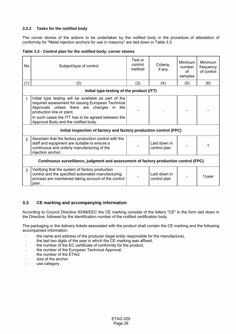
3.2.2 Tasks for the notified body The corner stones of the actions to be undertaken by the notified body in the procedure of attestation of conformity for "Metal injection anchors for use in masonry" are laid down in Table 3.3. Table 3.3 - Control plan for the notified body; corner stones
No Subject/type of control
Test or control method
Criteria, if any
Minimum number
of samples
Minimum frequency of control
(1) (2) (3) (4) (5) (6)
Initial type-testing of the product (ITT)
1 Initial type testing will be available as part of the required assessment for issuing European Technical Approvals unless there are changes in the production line or plant. In such cases the ITT has to be agreed between the Approval Body and the notified body.
- . - -
Initial inspection of factory and factory production control (FPC)
2 Ascertain that the factory production control with the staff and equipment are suitable to ensure a continuous and orderly manufacturing of the injection anchor.
- Laid down in control plan - 1
Continuous surveillance, judgment and assessment of factory production control (FPC)
3 Verifying that the system of factory production control and the specified automated manufacturing process are maintained taking account of the control plan.
- Laid down in control plan - 1/year
3.3 CE marking and accompanying information According to Council Directive 93/68/EEC the CE marking consists of the letters "CE" in the form laid down in the Directive, followed by the identification number of the notified certification body. The packaging or the delivery tickets associated with the product shall contain the CE marking and the following accompanied information:
- the name and address of the producer (legal entity responsible for the manufacture), - the last two digits of the year in which the CE marking was affixed, - the number of the EC certificate of conformity for the product, - the number of the European Technical Approval, - the number of the ETAG - size of the anchor - use category
Page 28

ETAG 029
Example of CE marking and accompanying information:
Letters "CE"
1234 Identification number of notified certification body Any Company Street 1, City,
Country Name and address of the producer (legal entity responsible
for the manufacture)
10 Two last digits of year of affixing CE marking 1234-CPD-0321 Number of EC certificate of conformity
ETA-06/2135 Number of European Technical Approval ETAG 029 ETAG number
M10 / Use category b,c and w/w size / use category 3.4 Marking of the product Every injection anchor shall be clearly identifiable before installation1) and shall be marked by:
- the name or identifying mark of the producer - the injection anchors identity (commercial name) - the intended use (durability use, e.g. an additional mark for stainless steel anchors to
distinguish them from non-stainless steel anchors). The intended use may be included in the injection anchor identity.
- the minimum anchorage depth or the maximum admissible thickness of the fixture - if an injection anchor is designed for use at more than one anchorage depths while maintaining the
same thread diameter, the anchorage depths available and used shall be discernible after installation of the injection anchor.
1) For use of commercial standard rods see 4.3 4 ASSUMPTIONS UNDER WHICH THE FITNESS FOR THE INTENDED USE IS ASSESSED 4.1 Design method for anchorages The assessment of the injection anchor shall be made assuming that one of the design methods given in Annex C is used. However, if an alternative design method shall be proposed, the Approval Body shall judge this design method and the relevance of the assessment, in particular the relevance of the tests to be undertaken. The overall assumption shall be made that the design and dimensioning of anchorages is based on technical considerations and in particular the following:
- the preparation of verifiable calculation notes and drawings for determining the relevant masonry in the region of the anchorage, the loads to be transmitted and their transmission to the supports of the structure.
- consideration not only of direct loads but also the important additional loads caused by restraint of
intrinsic (e.g. shrinkage) or extrinsic deformation (e.g. by temperature variations) in the injection anchor, in the fixture or in the base material together with verification of the distribution of loads in these structures and assemblies.
Page 29

ETAG 029
4.2 Packaging, transport, storage of the product Any special transport conditions shall be stated on accompanying documents. Any special storage conditions shall be stated on packaging including Storage temperature range Restrictions such as keeping away from heat and direct sunlight Expiry date. 4.3 Installation of the product in the works The loading capacity and reliability of anchorages are greatly affected by the manner in which the injection anchors are installed. The manufacturer’s installation instructions therefore form a fundamental part of the assessment of the fitness for use of an injection anchor. This Guideline takes account of a reasonable degree of imperfection in relation to installation and thus control methods on site after installation will in general not be necessary. This assumes, however, that gross errors on site will be avoided by use of instructions and correct training of the installers and supervision on site. The anchor shall be used only as supplied by the manufacturer without exchanging the components of an anchor. Commercial standard threaded rods, washers and hexagon nuts may also be used if the following requirements are fulfilled:
1. Material, dimensions and mechanical properties of the metal parts (rod, washer, nut) according to the specifications given in an Annex XX of the ETA Remark: The Annex XX has to contain all details of the metal parts. The material of stainless steel is given according to EN 10088:2009 [5], the mechanical properties according to EN ISO 898-1 and 2:2009 [8] (galvanised steel) and according to EN ISO 3506-1 and 2:2009 [4] (stainless steel) respectively.
2. Confirmation of material and mechanical properties of the metal parts by inspection certificate 3.1
according to EN 10204:2004 [9]; the documents shall be stored.
3. Marking of the rod with the envisaged embedment depth. This may be done by the manufacturer of the rod or the person on job site.
Installation instructions shall typically include the following:
- Before placing an injection anchor, the checks to be made to ensure that the use category applies and the strength class, density etc. of the base material is not lower than that to which the characteristic loads apply.
- Holes to be drilled perpendicular to the surface unless specifically required otherwise by the manufacturer’s instructions.
- Normally hard metal hammer-drill bits in accordance with ISO or National Standards shall be used. - All special drill bits (e.g. stopdrills or diamond core drill bits) required in accordance with manufacturer’s
installation instructions to be in compliance with the manufacturer’s specifications. This may be checked by comparing the drill bit manufacturer’s declared performance and characteristics against the specifications of the anchor manufacturer.”
- Instructions for hole cleaning shall specify in detail the type of cleaning equipment to be used, e.g. the volume of blow out pump and diameter and material of brush, together with the precise cleaning procedure including the number and order of blowing/brushing actions.
- Injection anchors to be installed ensuring not less than the specified embedment depth. The edge distance and spacing to be kept to the specified values, no minus tolerances to be allowed.
- Remark to the different installation temperature Temperature limits The following temperature limits shall be specified: Installation ambient temperature range Bonding material installation temperature range. Operational time limits
Open time and curing time shall be stated in relation to the relevant temperature limits, e.g.: Open time related to bonding material installation temperature Curing time in relation to installation ambient temperature
Page 30

ETAG 029
If tables are used to indicate times-versus-temperature ranges, they shall be inclusive so that the relevant time is clear for all temperatures within the appropriate range. An accepted example is given in the following:
Installation ambient Curing time temperature °C (minutes) E.g. 5 - 15 120 min 16 - 25 60 min
The following example is not accepted: Installation ambient Curing time temperature °C (minutes) 5 120 min 15 60 min
When curing times are stated it shall be made clear that this is the earliest time that the injection anchor may be torqued or loaded. A longer waiting time may be recommended for proof of ultimate load tests on site, if so, this shall be stated.
Finally it is assumed that the necessary information and appropriate specifications for correct installation are available on site and that the person responsible transmits all the necessary information to the installer. It is to be further assumed that installation is carried out by trained personnel under the supervision of the person responsible for technical matters on site. Where pictograms are used their meaning shall be clear and unambiguous. If necessary, text in the appropriate language shall be added to clarify the meaning. 5 IDENTIFICATION OF THE CONSTRUCTION PRODUCT In order to ensure that the injection anchor samples used for the initial assessment conform to the specification referred to in the approval, it is necessary to identify their relevant specifications and characteristics which can influence their functioning, performance or durability. Identification tests are for verifying the characteristics of the injection anchors, including dimensions, constituent materials, anti-corrosion protection and the marking of the injection anchors and various components. Wherever possible, checks shall be carried out on finished components. Where dimensions or other factors prevent testing to a recognized standard, e.g. tensile properties where the required ratio of length to diameter does not exist in the finished component, then the tests shall still be carried out on the finished component if practicable, in order to produce results for comparison purposes. Where this is not possible, tests shall be carried out on the raw material; however, it shall be noted that where the production process changes the characteristics of the material, then a change to the production process can render the results of these tests invalid. A minimum number of each component depending on factors such as the production process and the bag size is to be taken and dimensions measured and checked against the drawings provided by the manufacturer. The tolerances specified for all components shall be complied with and the dimensions of these elements shall conform to the appropriate ISO or European standards where relevant. The results obtained shall be assessed to ensure that they are within the manufacturer’s specification. The product which is the subject of the European Technical Approval shall be identified by:
- Testing of product characteristics as laid down in the following. - Fingerprinting. - Formulation. - Manufacturing process parameters. - Calculations, detailing, drawings.
Page 31
ETAG 029
Metal parts: During tests on the constituent materials of the components of the metal parts, the following properties shall be determined: tensile strength, elastic limit, elongation at rupture, hardness. The measured values shall be compared with minimum values or strength classes indicated in ISO or European standards. The manner in which the components are fabricated shall also be checked (e.g. cold-forming, quenching, hardening). For the testing of carbon steel screws, bolts, nuts, reference can be made to ISO 898-1 and 2:2009. For the testing of stainless steel screws, bolts, nuts reference can be made to ISO 3506-1 and -2:2009. For quenched components, the surface hardness and case depth are to be determined. Hardness testing shall be by either the Brinell or Vickers methods. Wherever possible, the material declaration, according to the relevant material standard, shall be provided. Bonding material: All components of the bonding materials shall be described in a chemically unambiguous way and be identified by standard tests (e.g. fingerprinting tests). All component amounts shall be specified either by mass, volume or percentage, with appropriate tolerances. The following characteristics shall be specified where relevant in accordance with ISO, European or national standards, together with any others as appropriate.
1 Organic Bonding agents Resin, hardener and additives shall be identified by the following tests: - density - viscosity - ignition loss and ash content - conventional dry extract - grain size analysis - tensile strength - bending strength - compressive strength - open time - reactivity (gel or setting time) (this may be tested with a standardised formulation, not necessarily that specified for the bonding anchor). In addition, the following tests are necessary: Resin and hardener cured by polyaddition mechanism Epoxies - epoxy index (equivalent) - amine equivalent Polyurethanes - hydroxyl equivalent - isocyanate equivalent Resin and hardener cured by polymerisation Unsaturated polyester, vinylester (epoxymethacrylates) and vinylesterurethanes (urethanmethacrylates) - hardener (catalyst) content of peroxide Methylmethacrylates (MMA) - hardener, content of peroxide Filler - specification of filler material (e.g. tested by density) including type - specification of filler shape (e.g. fibre, balls, ...) - grain size analysis
Page 32
ETAG 029 Page 33
2 Inorganic bonding agents - material specification by chemical analysis - active binder batching - grain size analysis - density - dry extract - setting test - shrinkage and swelling test - bend and compressive strength at 7 and 28 days - ignition loss and ash content Filler, additives - specification of filler material and additives - specification of filler shape
6 FORMAT OF ETAs ISSUED ON THE BASIS OF THE ETAG European Technical Approvals issued on the basis of this ETAG shall be in accordance with the ETA format given in the Addendum to the ETAG. 7 REFERENCE DOCUMENTS [1] Directive relating to construction products (CPD): Council Directive of 21 December 1988 on the
approximation of laws, regulations and administrative provisions of the Member States relating to construction products (89/106/EEC) taking account of the modified provisions (93/68/EEC)
[2] EN 771-1 to 5:2003 + A1:2005: Specification for masonry units [3] EN 12602:2008: Prefabricated reinforced components of autoclaved aerated concrete [4] ISO 3506-1 and 2:2009: Mechanical properties of corrosion-resistant stainless-steel fasteners – Part 1:
Bolts, screws and studs; Part 2: Nuts [5] EN 10088-4 and 5:2009: Stainless steels – Part 4: Technical delivery conditions for sheet/plate and strip
of corrosion resisting steels for construction purposes; Part 5: Technical delivery conditions for bars, rods, wire, sections and bright products of corrosion resisting steels for construction purposes
[6] EN 1996-1-1:2005: Design of masonry structures. Part 1-1: General rules for reinforced and
unreinforced masonry structure [7] TR 020:2004: EOTA: Evaluation of Anchorages in Concrete concerning Resistance to Fire [8I ISO 898-1 and 2:2009: Mechanical properties of fasteners made of carbon steel and alloy steel - Part 1:
Bolts, screws and studs; Part 2: Nuts [9] EN 10204:2004: Metallic products – Types of inspection documents [10] ISO 5468:2007: Rotary and rotary impact masonry drill bits hard metal tips – Dimensions [11] EN 1990:2002 - Eurocode 0: Basis of Structural Design [12] EN 1991:2002 - Eurocode 1: Actions on Structures