metal detector handbook
TRANSCRIPT

A book aboutmetal detectors,
covering detection proceduresin the field, and the
testing and evaluation of metal detectors
for humanitarian demining
Authors: Dieter Guelle, Andy Smith, Adam Lewis, Thomas Bloodworth
EUROPEANCOMMISSION


Metal detector handbookfor humanitarian demining
A book about metal detectors, covering detection proceduresin the field, and the testing and evaluation of metal detectors
for humanitarian demining
AuthorsDieter Guelle, Andy Smith, Adam Lewis, Thomas Bloodworth

Acknowledgements
We acknowledge help, advice and invaluable input from the following individuals. While they share in any merit thisbook may deserve, any errors and failings remain the authors’ alone.
For advice and assistance with technical aspects, special thanks to Yogadhish Das. For help and advice on a wide varietyof other aspects, our thanks to Jacky D’Almeda, Roger Hess, Tim Lardner, Russell Gasser, Ken O’ Connell, Franciska Borry,Marta Garotta, Gian Luigi Ruzzante, J. T. (Theo) van Dyk, Edgardo Maffia, Pete Hindy, and Chris Leach.
Many other people have helped in small ways — too many to mention by name. Our thanks to you all.
© All photographs and diagrams are copyright of the authors unless otherwise acknowledged.
Europe Direct is a service to help you find answers to your questions about the European Union
New freephone number:
00 800 6 7 8 9 10 11
A great deal of additional information on the European Union is available on the Internet.It can be accessed through the Europa server (http://europa.eu.int).
Cataloguing data can be found at the end of this publication.
Luxembourg: Office for Official Publications of the European Communities, 2003
ISBN 92-894-6236-1
© European Communities, 2003Reproduction is authorised provided the source is acknowledged. All photographs and diagrams are copyright of theauthors unless otherwise achnowledged.
Printed in Italy

Working in a research environment, it is always of con-cern when I am confronted with statements, like ‘To date,technology has had only a marginal impact on mineaction equipment.’ Therefore, it was a very rewardingmoment when, earlier this year, I was able to communi-cate the results of the European Committee for Standard-isation (CEN) working group on an agreement by an international community of experts on how to test andevaluate metal detectors to be used in humanitarian mineclearance.
During the work on the establishment of this workshopagreement, it became obvious that there are at least twoareas related to metal detectors that need furtherresearch. The first one is the electromagnetic characterisa-tion of soils and terrain in general terms, in order to pre-dict the performance of metal detectors in differentmined areas. The second one is the assessment of the per-formance of mine detection on the basis of reliable statis-tical testing. Work in both demanding areas of research isnow in progress.
In order to ensure that our research efforts will make animpact in humanitarian mine clearance, it is vital that theresults can be implemented by those working in the field.To achieve this, it is important to communicate the resultsachieved, through training sessions and presentations in adigestible way. It is therefore important to have hand-
books available, which present the actual state of knowl-edge and which are written by experts in both mine clear-ance and technical development in easily understandablelanguage. The handbook in front of you is such an example combining these vital ingredients.
An interesting point that arises from the handbook is thatdeminers working in the field can provide useful informa-tion to researchers and developers by making simplemeasurements to record the conditions that they meet,for example, by measuring the soil properties.
I am pleased that the Joint Research Centre (JRC) has beenable to contribute to the production of this handbookand I hope that it will soon become a reference for thosewho are confronted with the challenging task of mineclearance.
Dr Alois J. SieberHead of Unit,‘Humanitarian Security’
Institute for the Protection and Security of the Citizen (IPSC)
Joint Research Centre, European Commission, Ispra (VA), Italy
Foreword
3


Dear readers,
I have been using metal detectors of one kind or anotherfor over 20 years. First with the US Army, and for the lastfive years while establishing and managing humanitarianclearance programmes in the Balkans, Asia and Africa.Part of my role has been to train local deminers in how touse a range of different detectors in both shallow anddeep-level searches.
Over the last 10 years, detector designs have changed andthe features available have become more sophisticated.With this, I have had to learn constantly about thestrengths and weaknesses of the new equipment. Manu-facturers have usually done their best to assist, but theyrarely understand exactly what we need in the field or theconditions we will be using it in. So I have usually had tofind my own ways of getting the answers I was looking for.
Over the past 10 years, accidents have occurred becausedeminers and their supervisors have not understood thelimitations of the detector they were using. It is essentialfor the user to know the real detection depth that can beachieved at the task site and what is a safe rate of for-ward advance. Both of these depend on what the de-miner is searching for, but fortunately the smallest targetthat may be present in a particular area can usually bepredicted.
This handbook instructs the reader on how to confidentlyassess their detector’s ability in the place where they mustwork. The problem of electro-magnetic ground is ad-dressed in detail, including advice on how to predict theclearance-depth that will be possible in other areas. Thebook also includes detailed advice on how to conduct com-parative trials of metal detectors.
None of this is theoretical. It is all based on genuine hands-onexperience and the solutions are practical to use in the field.The book includes a quick field-user index and is even printedon tough, washable paper so that it will survive field-use.
For those who want to understand how detectors work inmore detail, there is a technical chapter. Even this is writ-ten in simple language so that most people will be able tounderstand it.
I recommend all trainers to read this book and all sitemanagers to carry a copy into the field. If the rules out-lined in this book are followed and adapted when neces-sary, deminers/operators will be safer and we will all beable to have greater confidence in the depth and thoroughness of clearance that has been achieved.
Cheers,Roger Hess
Demining and Explosive Ordnance Disposal TechnicalConsultant
Introduction
5


Throughout this book, the following abbreviations andacronyms are used.
ADP Accelerated Demining Programme
AG anti-group (mine)
AP anti-personnel (mine)
AT anti-tank (anti-vehicle) (mine)
CCW United Nations Convention on ConventionalWeapons
CEN European Committee for Standardisation
CWA European Committee for Standardisation workshop agreement
DDAS Database of Demining Accidents
DNT dinitroluene
EDD explosive detecting dog
EDR explosive detecting rat
EIT electrical impedance tomography
EM electromagnetic
EMI electromagnetic interference
EOD explosive ordnance disposal
ERW explosive remnants of war
FFE free from explosive
FNA fast neutron analysis
GC ground compensating (of metal detectors)
GICHD Geneva International Centre for HumanitarianDemining
GPR ground-penetrating radar
GPS Global Positioning System
GRH ground reference height
HD humanitarian demining
HE high explosive
ICBL International Campaign to Ban Landmines
IMAS International Mine Action Standards
IPPTC International Pilot Project for Technical Cooperation
Abbreviations and acronyms
7

8
IR infrared
ITEP International Test and Evaluation Programme
ITOP International Test Operational Procedures standards
NATO North Atlantic Treaty Organisation
NGO non-governmental organisation
NQR nuclear quadrupole resonance
PE plastic explosive
QA quality assurance
RDX Research Department Explosive (cyclonite)
SD self-destruct
SDA self-deactivate
TNA thermal neutron analysis
TNT trinitrotoluene (explosive)
UN United Nations
UNADP United Nations Accelerated Demining Programme
UNMAS United Nations Mine Action Service
UXO unexploded ordnance
WWI World War One
WWII World War Two

To prevent constant repetition, the authors have adoptedsome simple definitions that the reader should under-stand before reading the book. Each follows what webelieve is the ‘normal’ field-use of terminology.
Contaminated ground: The expression ‘contaminatedground’ is used to refer to ground with pieces of manu-factured metallic material in it. The metallic material maybe fragments from explosive devices, bullets, casings ordiscarded material with a metallic content.
Detector sensitivity: The expression ‘detector sensitiv-ity’ is used to refer to the metal detector’s ability to locatea target at varying depths, so is directly related to the dis-tance from the search-head at which a target can be
detected. The greater the distance between the search-head and the target at which a detector signals, thegreater its ‘sensitivity’.
Magnetic ground: The expression ‘magnetic ground’ isused throughout this book to indicate ground that haselectro-magnetic properties that make a metal detectorsignal. The cause may be spread throughout the groundover a wide area, or may be erratic such as when somerocks, stones or building blocks make the detector signal.
Search-heads or coils: Metal detector search-heads aresometimes called the ‘coil’ or ‘coils’. Throughout this bookthe terms are used to refer to the same part of the metaldetector.
Definitions
9


2.3.3. Batteries 342.3.4. Locating metal/mines 35
2.4. Using metal detectors 38appropriate for the threat2.4.1. Tripwires 382.4.2. Minimum metal mines 402.4.3. Fragmentation mines 402.4.4. Anti-vehicle mines 412.4.5. Detecting deep-level 41
explosive remnants of war
2.5. Targets for routine 44metal detector checks
2.6. Real mined areas 452.6.1. Grassland 462.6.2. Woodland 472.6.3. Open hillside 482.6.4. Unsurfaced roads and tracks 492.6.5. Surfaced roads, railway tracks 502.6.6. Urban (town or city) 512.6.7. Village 522.6.8. Mountain (high altitude, 53
steep gradient)
2.6.9. Desert 542.6.10. Paddy field 55
Contents
11
Chapter 1: Background to humanitarian 15demining
1.1. The development of mines 18
1.2. Detecting mines 201.2.1. Manual detection 21
using metal detectors
1.2.2. Manual detection 22using area excavation
1.2.3. Explosive detecting 22dogs and manual methods
1.2.4. Mechanical and manual 23methods
1.3. Treaties controlling mine use 23
Chapter 2: The role of metal detectors 27in humanitarian demining
2.1. Types of mined areas 28
2.2. Using metal detectors 29during surveys
2.3. Using metal detectors 30in area demining2.3.1. Daily routines 302.3.2. Test-pieces 32

12
2.6.11. Semi-arid savannah 562.6.12. Bush 57
Chapter 3: Detector standards and detector 59test standards
3.1. International standards 59for metal detectors
3.2. International standards 60for metal detectors in humanitarian demining
3.3. European Committee 61for Standardisation workshop agreement (CWA 14747:2003)3.3.1. What is covered by the 61
detector test agreement?
3.4. Previous metal detector tests 62in humanitarian demining3.4.1. Why so many field trials? 64
3.5. The output of humanitarian 64demining detector trials
3.6. Output of the international 66pilot project for technical cooperation trials3.6.1. Tests in air 663.6.2. Tests in the ground 673.6.3. Tests in the field 67
3.6.4. Miscellaneous tests 68
3.7. Output of other tests/trials 68
3.8. Do current detectors match 72the needs in humanitarian demining?
3.9. Lessons for future tests/trials 733.9.1. Data collection/analysis 74
during field tests/trials
Chapter 4: Metal detector technology 77
4.1. How metal detectors work 77
4.2. Electromagnetic properties 79of materials
4.3. Metal detector working 80principles4.3.1. Pulsed induction versus 80
continuous wave
4.3.2. Frequency-domain versus 83time-domain
4.3.3. Single coil versus separate 83excite/receive coils
4.3.4. Static and dynamic modes 834.3.5. Single receive coil versus 84
double-D (differential) receive coils
4.3.6. Bipolar pulse versus 85unipolar pulse

13
4.3.7. How are metal detectors 86designed for demining different from other types
4.3.8. What is important from 86the user’s point of view?
4.4. Suppression of electromagnetic 87interference
4.5. Ground compensation 88
4.6. How the electromagnetic 91properties of materials are quantified4.6.1. Conductivity and resistivity 914.6.2. Magnetic susceptibility 92
and permeability
4.7. Factors that affect detection 924.7.1. The metal object or ‘target’ 934.7.2. Distance between 93
the detector’s search-head and the metal object
4.7.3. Ground properties 95
4.8. Metal detectors, radar 96and radio waves
Chapter 5: Training 97
5.1. Deminers and their basic 97training requirements
5.2. Training in the use 99of metal detectors
5.3. Recommendations for trainers 1005.3.1. Self preparation 1005.3.2. Trainee assessment 1005.3.3. Structuring your training 102
5.4. The training content 1045.4.1. Assuring trainee competency 1055.4.2. Search-head sensitivity 105
profile (footprint)
5.4.3. Determining a field-accurate 108sensitivity profile (footprint)
5.4.4. Discriminating adjacent targets 1095.4.5. Stacked signals 1095.4.6. Linear metal targets 1095.4.7. Electromagnetic disturbance 1105.4.8. Pinpointing targets 110
5.5. Work in ‘prepared’ 111and ‘unprepared’ areas
5.6. Rescue/evacuation 112using metal detectors
Chapter 6: The use of metal detectors 115in mined areas
6.1. The detector ‘set-up’ 116
6.2. Adjusting for different ground 118

14
6.3. Adjusting to specific targets 120
6.4. Discrimination 121of ‘innocent’ metal
6.5. Action on getting 122a detector signal
Chapter 7: The way forward 127
7.1. Lies, damned lies and statistics 127
7.2. Reducing false alarms 128
7.3. Incremental improvements 1297.3.1. Incremental advances 129
in metal detection
7.3.2. Incremental advances 130in other technologies
Annex A: Explosive detecting dogs (EDDs) 131
Annex B: Other explosive remnants 135of war detection methods
Annex C: Explosive content of mines 151
Annex D: CWA 14747:2003 test overview 157
Annex E: Calibration of the Schiebel AN19/2 M7 159
Annex F: Suggested further reading 161
INDEX
Quick reference index for field users 163
Main index 165

While aspects of mine clearance have been a part of mili-tary procedures for more than 80 years, the specialisedclearance of all explosive remnants of war (ERW) onlybegan in the late 1980s when civilian organisations start-ed humanitarian demining (HD) in Afghanistan and Cam-bodia. HD involves clearing ground that has no militarysignificance and where all explosive items must beremoved or destroyed to a recorded depth. This is done inorder to support peacetime activities and protect civiliansfrom ERW injury. By contrast, military demining is usuallycarried out for strategic purposes and under pressure towork quickly. Often, only a route through a mined area iscleared. In return for speed, the military may find itacceptable to use armoured vehicles or take losses amongtheir soldiers. Well-equipped forces will usually clearroutes mechanically, avoiding putting personnel on theground. Land ‘cleared’ in this way is not safe for civiliansto use. In humanitarian demining, the deployment ofpeople to clear the ground is routine — and it is notacceptable to take losses among deminers or among thecivilians who will use the land at a later time.
Still in its adolescence, HD was started by charity-fundednon-governmental organisations (NGOs). Their lead wasquickly followed by United Nations (UN) supported pro-grammes largely staffed by seconded military personnel.Before long, commercial demining companies had sprungup, offering more cost-effective clearance to the donors.Huge variations in working speed and methods raised ques-tions over the quality of the work and opinion over safetyvaried widely. The need for the industry to adopt agreedminimum standards became obvious at the UN-sponsoredInternational Conference on Mine Clearance Technology (1)held in July 1996, in Copenhagen. The process of definingand implementing international standards began. In 1997,the first international standards for humanitarian demi-ning were published. The move towards adopting interna-tional standards continued with the United Nations MineAction Service (UNMAS) publication of greatly revised International Mine Action Standards (IMAS) in 2001 (2).
The IMAS defines ‘demining’ in the HD context as: ‘theclearance of contaminated land by the detection, removal
(1) http://www.un.org/Depts/dha/mct/(2) http://www.mineactionstandards.org/imas.htm
Chapter 1: Background to humanitariandemining
15

16
or destruction of all mine and unexploded ordnance(UXO) hazards’ (3).
With the ink still wet on the international standards thereis some way to go before they are universally adopted. Insuch a young ‘industry’, it is not surprising that there arevery few specialist publications dealing with particularaspects of HD. What is published is often of more interestto scientists and researchers than to the men and womenactually clearing the ground. This book is primarily writ-ten for those training deminers but may also be of use toscientists and researchers.
In Cambodia and Afghanistan, where formal HD began, theERW problem was the result of protracted conflicts resul-ting from the East–West divide and the cold war. Similarly,communist–capitalist ideologies fuelled the long-term con-flicts in Angola and Mozambique and led to the wide-spread contamination of ground. In the Balkans, it was thepolitics surrounding the end of the cold war that fuelledconflicts in what had been a weapons-producing area.Again, mines and other ordnance were often used withoutconcern for the long-term threat. From Lebanon toNamibia, Bosnia and Herzegovina to Vietnam, andGuatemala to Peru, the ERW left over after conflicts takes asteady toll on lives and limbs, and prevents safe reconstruc-tion. Actual numbers of dangerous items on the ground arenot known, but it is known that huge areas of land are
abandoned and that this inhibits the transition to peace inmany ways, crippling the lives of many in the process.
The ERW that has received most publicity are mines andbooby traps that are designed to be victim activated andso pose a great threat to post-conflict civilians. But manycivilians are also injured by unexploded ordnance and bymunitions that may have been poorly stored and havebecome unstable. Sometimes the civilians are injuredwhen trying to recycle the explosive and metal content ofERW in order to earn a little money.
Humanitarian deminers do not only clear mines. Theymust also clear all ERW and leave the area safe for itsintended use. Sometimes this means that an area must besearched to a considerable depth to find all unexplodedordnance. This is usually necessary when there are plansto carry out construction on the site of a former battle orbombing site.
To date, the manual deminer has usually relied on a metaldetector to help locate concealed ERW. Until recently, thedetectors used had all been designed for military usebecause the HD market did not warrant the investmentrequired to develop new models. This meant that thedetectors often had features that were not necessary ordesirable in HD, but those features sometimes increasedthe price. For example, some detectors are supplied with
(3) Annex A of the International Mine Action Standards (IMAS), Section 01.10, Paragraph A1.2. http://www.mineclearancestandards.org, the text in bold is the authors’.

17
a case that is infrared (IR) invisible allowing it to be back-packed in a conflict without showing up on the enemy’sIR night-sights. This expensive feature is entirely irrelevantin HD. Most of the detectors were primarily designed tobe used for short periods while standing. In HD, it isincreasingly common for short detectors to be used whilekneeling, squatting or bending — and to be switched onfor six hours or longer every working day.
Manufacturers of many of the latest generation of metaldetectors have listened to the needs of HD and tried todesign for its needs as well as the military. Many newerdesigns are intended to be used while kneeling, squattingor bending and most now have the option of a speakerinstead of headphones. The best are simple and robustenough for fairly constant use in difficult conditions.
Perhaps of most importance, detector designers haveincreasingly listened to the HD need for a detector capa-ble of locating small metal pieces in ground that has elec-tromagnetic properties that can make detectors signal asif metal were present (4). This feature is also of occasionalbenefit to military purchasers, although the higher sensi-tivity may slow down the process of crossing a minedarea. When the military have to use metal detectors, itcan be a high priority to minimise the number of detectorsignals that would slow down the process of crossing the
mined area. When operating under fire or with a tighttime constraint, tiny scraps of rusted metal are often seenas ‘false alarms’. While minimising false alarms is also aconcern in HD, any piece of metal is generally not seen asa ‘false alarm’ at all. In areas cleared by metal detectors, itis common for the quality assurance (QA) check to requirethat the area be metal-free, so every scrap of metal mustbe removed. In HD, it is always better to spend time dig-ging up a nail than to suffer an injury.
In some cases, demining groups may choose to tunedown a sensitive detector so that it does not signal onvery small metal pieces. This is done when the devices inthe area are known to include relatively large amounts ofmetal, and when other hazards can be confidently exclud-ed. If this is done, any QA checks carried out with detec-tors on that ground must be carried out with the samedetector tuned to the same level of sensitivity. In these circumstances, some groups prefer to use explosivedetecting dogs (EDDs) for QA.
Despite the desire of many detector manufacturers tosupply what is needed in HD, the commercial realityrequires that they also try to sell for military use. As withother equipment used in HD, the potential market is justnot big enough to warrant the development of modelsdesigned solely to meet humanitarian demining needs.
(4) Very few detectors had ground-compensating features between WW II and the beginning of the 1990s.

18
1.1. The development of mines
Victim-initiated explosive devices, placed under, on, ornear the ground, have been used in war for centuries (5).The earliest ‘mines’ were probably underground tunnelspacked with explosive and detonated beneath the enemy.This is how they got their name. Today we understand‘mines’ to mean containers filled with explosive that areinitiated by the victims or their vehicles. Developed duringWorld War One (WWI), these began to be widely usedduring World War Two (WWII). Seen as a ‘force-multiplier’, they allowed the users to:
(a) provide a defensive barrier around vulnerable sitesand utilities. The initiation of the mines would pro-vide early warning of attack and, if dense enough,the mined area might stop an attack in its tracks;
(b) channel enemy troops and vehicles into an unminedarea where they themselves would be vulnerable toattack;
(c) deny the enemy safe access to utilities they might need,even after those placing the mines had withdrawn;
(d) assist in surprise attacks and ambushes.
Some of these uses required that the enemy knew themines were there, others relied on surprise. The nature of
the conflict and the professionalism of those engagedhave affected the way in which mines are used. In con-flicts where the opponents have large differences in mili-tary equipment and capability, such as insurgency wars,the less well-equipped groups have tended to make max-imum use of unmarked ‘surprise’ mines. In conflicts whereone side has no desire permanently to occupy the territory, the use of unmarked minefields is common.
With the increased use of mines, methods of detectingthem began to emerge. Early mines were usually cased inmetal, so the development of metal detectors as mine-detectors began.
The early detectors were relatively crude devices requiringa lot of power. To minimise their metal content, thedetector heads were first made using wood, then hardplastic (Bakelite). Often heavy and awkward to use, theyallowed paths to be cleared through areas sown withmetal-cased mines.
Anxious to maximise their military effectiveness, minedesigners responded to the use of metal detectors byreducing the mines’ metal content. They used wood andBakelite to make the mine bodies and they began toreduce the metal content in the firing mechanism. Thiscoincided with the rapid development of a wide range ofsmall mass-produced mines designed to be initiated by aperson’s weight — anti-personnel (AP) blast mines — and
(5) Those interested in the history might like to read the accounts by Schneck, Grant, McGrath, and McCracken (see Annex F).

19
anti-personnel fragmentation mines, sometimes calledanti-group (AG) mines, that were often tripwire initiated.Since WWI, early versions of these mines had beendeployed to inhibit infantry movements in the same wayas anti-tank (AT) mines were used to restrict the use ofvehicles. During WWII, AP mines were increasingly used toprotect AT mines so that a person attempting to clearthem with an insensitive metal detector would step on anAP mine laid nearby.
Some old designs of AP blast mine were still in wide-spread use recently, notably the PMN and GYATA-64.These will usually remain functional for at least 25 yearsafter being placed. Many other early designs are nolonger used and so are rarely found, but they may remainin military stores and so remain a threat. The earlier minesusually contained significant metal in the parts of theirfiring mechanism and also between 100 and 300 g of highexplosive. Later AP blast mines (such as the M14, PMA-3and Type 72 AP) contained much less explosive, whichallowed them to be smaller, cheaper to produce and easier to conceal. The increased reluctance to risk foot-soldiers in conflict led to the development of ‘scatterable’AP blast mines that were dispersed from vehicles, helicop-ters or as submunitions dispersed from a canister in theair. These were used in such numbers that enemy soldierswere denied use of the target area. Ignoring earlier con-ventions, these mined areas could not be easily mappedor marked and are almost always poorly defined.
Some of the simplest early fragmentation mines are stillfound widely, notably the POMZ-2 and POMZ-2M which areeasily reproduced locally. A more complex and (in militaryterms) more effective fragmentation mine is the boundingtype. These mines are propelled above the ground beforeexploding and sending lethal fragments in all directions.While many of the early designs of bounding fragmenta-tion mines have been abandoned, the OZM range is stillfound in many areas and the later generation PROM-1 andValmara-69 are infamous for having claimed the lives ofmore humanitarian deminers than any other mines.
Figure 1.1:An early mine detector with a wooden search-head.The extra pole is a handleextension and leadcounterweight. This is the PolishMk3 as used by the British armyduring WWII. The full length of the handle is over 2.5 m.

20
Another category of fragmentation mine is the ‘directionalfragmentation’ or ‘off-route’ mine. On detonation, thesespread pre-cut metal fragments in a limited arc from oneside. Designed to be used by people who remain behind themine, they are often detonated by a soldier at the appro-priate time (as in an ambush). When fitted with a command-detonation fuze, these devices are not techni-cally ‘mines’ according to the definition agreed in the con-vention to limit use of AP mines (see Section 1.3).
Scatterable fragmentation mines have also been devel-oped, sometimes deployed with remotely placed AT minesas submunitions dispensed from cluster bombs. As withscatterable blast mines, the method of remote deploy-ment means that the mined area is usually unmarked andpoorly defined.
1.2. Detecting mines
In humanitarian demining, the common methods ofdetection in current use are:
• manual, using metal detectors;
• manual, using area excavation;
• dogs and manual;
• mechanical and manual.
Notice that all include the use of manual deminers. This isbecause, to date, the industry has not accepted that anyfully mechanised method of ground processing can findand remove all ERW. The machines have not yet matchedthe mental and physical attributes of the deminers.
Figure 1.2:The photograph shows twometal detectors used inhumanitarian demining and illustrates the way thatmetal detectors have developed.On the left is the Schiebel AN19introduced in the 1980s,for years the workhorse of the industry. More moderninstruments are now availablefrom several manufacturers(including Schiebel themselves).On the right is an example,the Foerster Minex 2FD 4.500,which features an extendableone-piece design and groundcompensation (GC).

21
1.2.1. Manual detection using metal detectors
All deminers know that their most reliable detection toolsare their eyes and brains. It is often evident where minesare placed, and in many cases parts of the device are visi-ble after the undergrowth has been removed. This isoften true with recently placed AP mines of all types, andsometimes true of AT mines. But when mines were placeda decade or more ago, they have often become moredeeply concealed. Even when partly exposed, their caseshave weathered and may be impossible to see. Whereland erosion or the deposit of alluvial sediment occurs,mines can move from their original place or becomeburied deeply beneath ‘new’ soil. New alluvial soil is veryfertile and can be thick with roots that the mine is tan-gled inside. Apart from those areas, deeply buried APpressure mines are usually only found in areas that weremined many years ago. In a few cases, AP mines weredeeply buried on placement, despite the fact that thismade it less likely that they would explode as designed.The presence of deeply buried mines, or the belief thatthey may be present, can slow demining down a greatdeal and so increase the cost.
As long as the ground is not too naturally magnetic orcontaminated by scrap metal, manual deminers rely onmetal detectors to locate the metallic parts of mines andUXO that cannot be seen.
The metal content of fragmentation mines is so high thatthey do not normally present a detection problem. Also,
most of them are designed to be laid with their fuzemechanism above ground, and many are placed with halftheir body exposed, so they are often easy to see after theundergrowth has been removed.
The reduction of metal content in AP blast mines over theyears has led to a few modern mine designs having no metalcontent. Thankfully, very few of these mines have foundtheir way into use and their manufacture and sale is now re-stricted by the terms of the 1997 Mine Ban Treaty (see Sec-tion 1.3). Some have been found during HD using dogs orexcavation. Of those known to the authors (notably the M1APD 59 found in Lebanon and Angola) the detonators ap-pear to have deteriorated and become non-functional aftera decade in the ground. It is to be hoped that similar prob-lems occur with other non-metallic fuze systems.
The detection and fairly accurate location of metal in theground is essential for deminer safety. It is not only neces-sary to get a signal, the deminer must also be able to cen-tre the reading and place a marker almost exactly wherethe metal is. This allows the deminer to start probing orexcavating a safe distance away from the reading. Thedeminer probes or digs sideways towards the reading soas to approach the device from the side and avoid press-ing directly onto the pressure plate of a mine. But minesare not always lying flat in the ground. If they have tilted,a cautious deminer can still set the mine off. Detonating amine while exposing it is the most common accident inHD. When adequately protected, most deminers survivethis without disabling injury.

22
1.2.2. Manual detection using area excavation
In areas where magnetic ground or scrap metal contami-nation is so high that a detector signals constantly, thedeminers may have to put the detectors aside and excavate the entire top-surface of the ground to anappropriate clearance depth. This ‘difficult’ ground may bea naturally occurring high level of magnetic ground inter-ference or may be caused by mankind. In many areas, nonatural magnetic ground occurs, but in all areas that havebeen occupied by people, some scrap metal contamina-tion occurs. In the experience of the authors, and as acrude ‘rule of thumb’, if more than three pieces of metalare found per square metre, it can be faster to excavatethe entire area than safely to excavate the metal piecesseparately. The excavation process is so slow that it is usu-ally only done in very limited areas where there areknown to be mines, although it has been done over longstretches of road. Explosive detecting dogs may be usedto reduce the suspect area to a minimum before startingto excavate.
If a mine has been deliberately buried deeply, as with anAT mine on an unsurfaced road, the removal of the top ofthe road may reveal where a deeper hole has been previ-ously dug and so allow the mine to be unearthed. How-ever, this is not always the case and the use of dogs tolocate the well-spaced mines on roads is usually preferred.
1.2.3. Explosive detecting dogs and manualmethods
Explosive detecting dogs may be used to reduce an areaprior to manual clearance, and occasionally for precise minedetection. To increase confidence, it is normal for at leasttwo dogs to be run over the same piece of suspect ground.It is generally accepted that dogs cannot reliably pinpointthe source of the explosive in a densely mined area wherethe scent from more than one source may combine. Dogscan only be used to pinpoint mines when the mines arewidely scattered. Where dogs are used to pinpoint explo-sives, one common method is to ‘box’ the area into 8–10 metre squares. The dogs are then run inside each boxedarea from which any dense undergrowth must have alreadybeen cleared (usually using an armoured machine). Whenthe dogs signal, a manual deminer then clears (using a metaldetector and/or excavation techniques) an area extendingseveral metres around the spot where the dog indicated.Sometimes the deminer must clear the entire marked ‘box’in which the dog indicated the presence of explosives. This isbecause it is recognised that the dog’s ability to pinpoint theposition of the explosive (and to discriminate two readingswithin a few metres of each other) may not be reliable.
Dogs are also used as a quality control check on land thathas been cleared, especially if the devices found have notbeen detonated where they were found. Destroying thedevices in situ can spread the explosive scent over a widearea, which means that there must be a time intervalbefore dogs can be reliably used to check the ground.

23
In all cases, the dog acts as a ‘detector’ and anything itdetects is investigated by manual deminers (6). For moreabout the use of dogs, see ‘Annex A: Explosive detectingdogs (EDDs)’. For an indication of the variety of types ofhigh explosive (HE) that a dog may have to locate, see‘Annex C: Explosive content of mines’.
1.2.4. Mechanical and manual methods
Machines are increasingly being used to assist in the man-ual demining process. The most common use is to cut theundergrowth before the deminers start work. Other usesinclude the use of back-hoes to remove and spread outbuilding rubble or the collapsed sides of trenches. Onroads and in open areas, they are increasingly being usedto carry one or another means of detection. This usuallyallows an array of detectors to be used, so potentiallyincreasing speed (7). More controversially, ground millingmachines, flails and rollers are sometimes used to deto-nate or destroy mines where they lie.
In all cases, to have confidence that all ERW has been re-moved, manual deminers must follow the machines. Some-times they may use dogs as detectors, often metal detectors.
1.3. Treaties controlling mine use
Two major international treaties control the use of land-mines: Protocol II to the Convention on ConventionalWeapons (CCW) of 3 May 1996 and the Ottawa
(6) At the time of writing, the GICHD does not have a dedicated website recording the research it is organising into the use of dogs.There are several relevant papers on the GICHD site, for example, http://www.gichd.ch/docs/studies/dogs.htm
(7) Currently, there are several vehicle-based metal detector arrays in existence and several prototype multi-sensor systems combiningother detection techniques such as GPR and NQR with metal detection (see ‘Annex B: Other explosive remnants of war detectiontechnologies’).
Figure 1.3:A mechanically prepared area being marked out for searching by dogs.

24
Convention or Mine Ban Treaty of 3 December 1997. Thefull names of these treaties are respectively:
Protocol on Prohibitions or Restrictions on the Use ofMines, Booby-Traps and Other Devices as Amendedon 3 May 1996 (Protocol II as amended on 3 May1996) annexed to the Convention on Prohibitions orRestrictions on the Use of Certain ConventionalWeapons Which May Be Deemed to Be ExcessivelyInjurious or to Have Indiscriminate Effects (8); and
Convention on the Prohibition of the use, stockpiling,production and transfer of anti-personnel mines andon their destruction (9).
Under the CCW, the manufacture of completely non-metallic anti-personnel mines is banned and other restric-tions are placed on anti-tank mines and booby traps aswell as anti-personnel mines. Mines designed to be acti-vated by metal detectors are banned. It is forbidden touse mines against other than military objectives. Almostall countries with a significant arms production capabilityare State parties to the CCW or have signed it.
Under the Ottawa Convention, anti-personnel mines areessentially banned completely. Its provisions do not applyto anti-tank mines. Many arms-producing countries havesigned it but those who have not include such major arms
producers as the United States, Russia and China. At thetime of writing, the existing, new and applicant MemberStates of the EU have signed and ratified it with theexception of Greece and Poland (signed but not ratified),and Finland, Latvia, Estonia and Turkey (not signed).
AP mines are often seen as the greatest threat to civiliansafter conflicts have ended, and the Ottawa Conventionwas built around them. The Ottawa Convention (and thepublic campaigning that surrounded it) has had an obvi-ous effect on AP mine production and deployment. Thedevelopment of metal-free mines has virtually ceased.Although there is continued disagreement about the mil-itary utility of AP mines, some of those who have notsigned the Ottawa Convention have agreed to increasethe metal content of their stocks of minimum metal minesso that they can be more readily detected. Others areseeking to perfect mines that self-deactivate (SDA) or self-destruct (SD) after a set period of time, so theoreticallyremoving the persistence of their threat to non-combatants. Currently, there is mixed opinion over whetherSD and SDA mines will perform as designed. There arealso concerns about clearing up SDA mines that havedeactivated, but still contain a detonator and high explo-sive and so remain a threat to civilians.
One unintentional effect of the Mine Ban Treaty may bethe increased use of other munitions that have an
(8) The text of CCW Protocol II can be found at http://www.unog.ch/frames/disarm/distreat/mines.htm(9) The text of the Ottawa Convention can be found at http://www.icbl.org/treaty/text.php3

25
area-denial effect similar to mines, but that are notdesigned as mines. An example of this is the BLU-97 sub-munition that has a high failure rate on impact and aninertia fuze system that can be sensitive to any latermovement. Where these have been used (most recently inIraq, Afghanistan, Kosovo and Kuwait), both deminersand civilians have been killed by them in relatively largenumbers. The BLU-97 is not the only submunition thatcauses these problems. The BL-755, M118 ‘Rockeye’, BLU-61, BLU-62 and KB1 are others. Some campaigners are cur-rently seeking to limit their use or change their design sothat they pose less of a threat when the conflict hasceased. At the time of writing, new protocols restrictingor banning these devices are being prepared for consider-ation as additions to amended Protocol II of the CCW. The
change in the public attitude to the use of indiscriminateand persistent weapons coincided loosely with the end ofthe cold war and the consequent reduction in ideologicalwars that were fought by proxy on foreign soils. In thosewars, mines were often seen as cheap and effective force-multipliers, and were provided in huge numbers to thecombatants by outside agencies. The scale of the mineproblem in Mozambique, Angola, Afghanistan and Cambodia dates from this time.
While the use of AP mines has declined, their continuedacceptance and use in non-signatory States such as Azer-baijan, Myanmar (Burma), Chechnya, China, India, Korea,Nepal, Pakistan, Russia, Sri Lanka and Uzbekistan indicatethat the ‘ban’ is far from complete.


The process of demining can be crudely divided into fivegeneral stages. Metal detectors may be used duringstages 1, 2, 3, and 5.
1. Locate the mined areas.
2. Determine where the mines are within the suspect area.
3. Locate each individual mine/UXO.
4. Destroy each individual item.
5. Check that the area is really clear before release tothe public.
Until recently, these were often referred to as:
1. Survey Level 1 — Country survey including impact survey
2. Survey Level 2 — Technical survey, area reduction
3. Mine detection/Demining
4. Demolition
5. Survey Level 3 — Quality control/Sampling
A further survey level (Survey Level 4), is sometimes usedto describe the subsequent searching of the area fordeep-level ordnance that would not be found without aspecialist deep-level detector (see Section 2.4.5, ‘Detectingdeep-level explosive remnants of war’).
The first version of the UN’s International Mine Action Stan-dards (IMAS) recognised the distinctions in survey levelslisted above. The 2002 revision of the IMAS uses the term‘General mine action assessment’ to cover what was re-ferred to in the earlier IMAS as ‘Survey Levels 1 to 3’, alongwith ‘Impact studies’, ‘Post clearance inspection’ and ‘Sam-pling’. The activities are combined under one heading be-cause this allows the survey and mine clearance process tobe seen as integrated and continuous, rather than as a se-ries of tasks that should be completed sequentially (10). Forexample, information that may be part of a general SurveyLevel 1 may only be discovered during a Level 2 technicalsurvey or actual demining, but provision should still bemade for it to be recorded and used during future planningand prioritisation tasks. No survey task should be thoughtof as being ‘finished’ until the clearance is completed andthe land returned to the users.
(10) See http://www.mineclearancestandards.org/links.htm
Chapter 2: The role of metal detectors in humanitarian demining
27

28
The term ‘Survey Levels 1 to 3’ is still widely used, but whatit actually involves varies in different parts of the world andmay be surprisingly limited. In most areas, a Level 1 surveydoes not involve placing perimeter signs around a suspectarea — so does not include any means of warning the pop-ulation that a danger exists. It is only during a Level 2 tech-nical survey that perimeter markings are placed. In manyareas a technical survey is not carried out separately, but aspart of ‘area reduction’ immediately prior to clearance, sothe area may be left unmarked for years.
The elements of ‘General mine action assessment’(described in IMAS 08.10) can be crudely expressed as:
1. emergency threat assessment/survey;
2. technical survey and clearance (including impact survey) — IMAS 08.20;
3. post-clearance documentation (including QA inspec-tions) — IMAS 08.30.
2.1. Types of mined areas
The use of a metal detector can be influenced by theplace where the mines are situated.
While every mined area is unique, common characteristics aresometimes identified in order to reach generalised conclu-sions. The following generic mined area ‘scenarios’ are takenfrom the Geneva International Centre for HumanitarianDemining’s (GICHD) study of global operational needs (11).
Grassland Open (flat or rolling) landWoodland Heavily wooded landHillside Open hillsideRoutes Unsurfaced roads and tracks,
including 10 m on either sideInfrastructure Surfaced roads, railway tracks
(to 10 m on both sides)Urban Large town or cityVillage Rural population centreMountain Steep and high altitude Desert Very dry, sandy environmentPaddy field Land allocated for the growing
of rice Semi-arid savannah Dry, open and flat, little
vegetationBush Significant vegetation
and possible rock formations
A scenario is assigned to each mined area. The scenario isthen refined by assigning defining characteristics, such asa description of the ground type, the level of magneticinterference and/or scrap metal contamination,
(11) Geneva International Centre for Humanitarian Demining, Mine action equipment: Study of global operational needs, Geneva,2002, ISBN 2-88487-004-0.

29
vegetation, slope, the presence of trenches and ditches,fences and walls, buildings and building debris, water-courses, ease of site access and the mine/UXO hazard. Thiswas done as part of an exercise to find out which HDactivities could most effectively be improved (see also Sec-tion 2.6, ‘Real mined areas’.)
Of special relevance to the use of metal detectors is the levelof naturally occurring magnetic interference and of scrapmetal that may be present. The level of metal detector ‘dis-turbance’ that results can be recorded using the GICHDmethod as ‘none’, ‘low’, ‘medium’ or ‘high’. The definitionof ‘medium’ includes a reduction in the ability to detectminimum metal mines and ‘an impact on safety and therate of clearance’. The definition of ‘high’ is that the distur-bance prevents ‘the use of conventional mine-detectors’.These conditions can occur in any of the listed scenarios.
The GICHD study allows a variety of conditions to beassessed as part of the HD planning process. The antici-pated threat is an integral part of this. For example, itmay be that the area has a medium level of ground ‘dis-turbance’ but that minimum metal mines were not usedthere, so reliance on appropriately tuned/adjusted metaldetectors may still be safe. However, there is not current-ly an industry-wide agreement about how the level of‘disturbance’ should be measured.
It may not be quite so obvious that the practicalities ofdemining with metal detectors can also be influenced byother factors. Examples are listed below.
(a) The terrain — steep and irregular land can make it im-possible or unsafe to use a detector in the way described ina group’s operating procedures. For example, the deminersmay need to change their normal safety distances, orchange the normal working position of deminers.
(b) Rocky ground — which can make it impossible to usethe group’s ‘normal’ marking procedures during detectionand clearance.
(c) Wet ground — which can inhibit the operation ofsome detectors and change the apparent level of whatthe GICHD study called ground ‘disturbance’.
2.2. Using metal detectors duringsurveys
The way in which mined areas are surveyed varies widelyaround the world. At some stage during the planning ofclearance, there should be a detailed survey in order forthe planning authority to decide which demining meth-ods and resources are appropriate to use in the suspectarea. During this, a metal detector can be used to gainsome indication of its ability to locate the target minesunder local conditions.
In some areas, a sloping cutting in the side of a trench canbe used to get a reasonable indication of a particular

30
detector’s ability to locate particular mines at variousdepths. This can be important when a clearance contractspecifies the depth to which the deminers must work. Thecavity around the mine may affect performance, so theresult should be checked by burying a target mine at themaximum detection depth.
2.3. Using metal detectors in areademining
Area demining is the clearance of ERW from land undergiven conditions. Some indication of how varied those con-ditions can be has already been given. To begin to under-stand how that variability can affect the use of a metal de-tector, the reader may like to look around the vicinity oftheir own homes assuming that everywhere is mined. Ifthey were to take a detector onto the nearest patch ofgrass, it is likely that they would get very many signals fromburied metal that has accumulated over the years. In realmined areas, the vegetation, moisture, magnetic ground,ground incline and many other features affect detector use.
Metal detectors cannot be used as mine-detectors every-where, but the latest GC models can be used in mostmined areas. Where they are used, some rules should befollowed to make their use as safe as possible.
2.3.1. Daily routines
The group’s operating procedures are approved routinesfor the deminer to follow. The daily detector routines arestanding (or standard) operating procedures (SOPs) likeany other and should be documented. As a general rule,it is very important to follow the instructions provided inthe manufacturer’s manual when setting any detector upfor optimal use.
Figure 2.1:The picture on the left showsFredrik Pålsson using a cuttingin the side of a trench duringdetector selection trials in Afghanistan during 1999.

31
While the manual may specify further checks, the follow-ing routines are the minimum checks that should be madebefore using any metal detector in a mined area.
(a) Checking the detector’s general condition. Checkthat the battery connections are tight and reliable,and (when possible) that the batteries retain a suit-able charge level. Check the detector for visible dam-age, loose screws or connections, and any other partsknown to fail or identified in the detector manual.Only after a detector has passed these checks shouldits functions be checked.
(b) Checking the detector’s functions. After assem-bling the detector, it must be checked to ensure thatit is working properly. This process has various names,but it is often called the ‘set-up’ or the ‘warm-up’.Detector manufacturers usually provide a sample tar-get for the detector to signal on. This is often called a‘test-piece’. Most test-pieces are not only designed toshow that the detector signals on metal. They are alsodesigned to indicate whether the detector signals onthe target at a set distance from the detector-head(usually in air). This is usually referred to as measuringthe detector’s ‘sensitivity’. After this test, the deminerknows whether the detector is functional. The timeneeded to conduct a ‘set-up’ test varies by detectortype, but is generally not more than a few minutes.
(c) Adjusting the detector to the ground condi-tions. Checks (a) and (b) are usually carried out in
strict accordance with the instructions found in thedetector’s manual. Adjustment to the ground condi-tions may also be adequately explained in the manual, but is often extended with the experience ofthe users.
A detector without a GC facility may simply be ‘tuneddown’ by reducing its sensitivity until it no longer sig-nals on the patch of pre-cleared ground used as a testarea. Detectors with a GC facility may be adjustedautomatically, or manually. In both cases, thedetector’s ability to detect at depth is frequent-ly reduced by the adjustment.
(d) Adjusting the detector to the target. This is themost important check because it can make the workboth safer and easier but it is not carried out by alldemining groups. It involves reducing the danger toone that is known. This is achieved by checking thatthe detector can find what the deminers are lookingfor. The most difficult target to find is selected. Thiswill often be a minimum metal mine but may be abigger metal target buried at a greater depth. Somedemining groups use real mines that have been ren-dered safe. Some demining groups use test-piecesthat simulate the detectability of the target mine. Thetarget is buried at the maximum clearance depthrequired and the detector is used to locate it.
This check is not only of the detector’s ability to dothe job required. It can also be used to check the

32
deminer’s ability to use the detector in the wayrequired. By carrying it out, the deminers are givenconfidence in the equipment and in their ability touse it. When it includes measuring the ‘sensitivityarea’ of the detector beneath the ground, it can alsoprovide vital information about how far to advancethe detector-head on each sweep (see Section 5.4.2,‘Search-head sensitivity profile (footprint)’). By inclu-ding this routine before work, the deminers areshown that those in charge care about their safety.The authors recommend that this check always be suc-cessfully completed before deminers are allowed towork in the mined area.
Routines while working in the mined area are listedbelow.
(e) Maintaining confidence. After check (d) above, thedeminers start to use the detectors to search for metalin the mined area. Many models of detector make asound to show that they are working normally. This isoften called a ‘confidence click’. Although the soundshould be enough to give confidence, deminers usual-ly feel a need to make their own regular check thatthe detector is working. This is done by routinely pre-senting the detector to a visible metallic target, suchas tools or the eyelets on the user’s boots.
(f) Repeating ‘set-up’ for changed conditions. Work-ing hours vary, but on average a metal detector isused for about six hours a day in HD. If the detector is
turned off during that time, checks (a) to (d) shouldbe repeated when it is turned back on. The ambientconditions in the work area will also change over asix-hour period. For example, the temperature andthe level of humidity may rise a great deal. Also, thecondition of the detector and its batteries canchange. As a result, all detectors should be ‘set up’again after a predetermined time. At the very least,set-up checks (a) to (d) should be repeated if there isa temperature change of 10°C.
(g) End-of-day check. The last routine at the end of theworking day is to clean and disassemble the detector,repeating check (a) in the process. The detector canthen be packed away ready for use the next day.
2.3.2. Test-pieces
Two kinds of detector test-piece are recommended: the‘manufacturer’s test-piece’ and a ‘confidence test-piece’.The manufacturer’s test-piece is usually supplied with aspecific detector. These test-pieces are small pieces ofmetal, often encased in plastic. They are used with a dis-tance scale to check that the detector is working properlyand achieving its design ‘sensitivity’.
The ‘confidence test-piece’ is either an original mine (freefrom explosive) or a surrogate designed to be a substitutefor the metal content of a mine. Some surrogates attemptto simulate a generic mine type rather than a particular

33
mine model. Some attempt to simulate a specific mine,and may be called ‘simulants’. The distinction betweenthe use of the terms ‘surrogate’ and ‘simulant’ is not uni-versal and the words are often used to mean the samething. Both surrogates and simulants may be designed tohave detection characteristics similar to those of realmines and so be used as substitutes for them when testingdetectors.
While we follow field-use and make no strict distinctionbetween ‘simulant’ and ‘surrogate’ in this book, a stan-dardised naming convention for mine targets exists as oneof the four-nation international test operational proce-dures standards (ITOP 4-2-521) and has been recognisedby the North Atlantic Treaty Organisation (NATO) (Stanag4587) (12). This convention defines ‘types’ in the followingway.
Type 1: Production mine — a fully ‘live’ mine.
Type 1a: Production mine — a mine with an active fuzebut the main HE charge removed.
Type 2: Surrogate mine — a production mine with a dis-abled fuze.
Type 3a: Surrogate mine — a production mine that isfree from explosive (FFE), air-filled.
Type 3b: Surrogate mine — a production mine that is FFEand filled with an inert material.
Type 4a: Reproduction mine — a model of a specific typeof real mine (air-filled).
Type 4a: Reproduction mine — a model of a specific typeof real mine (inert-material-filled).
Type 4c: Reproduction mine — a model of a specific typeof real mine (explosive-filled).
Type 5a: Simulant mine — a generic model of a class ofmine, with significant explosive fill.
Type 5b: Simulant mine — as 5a with an active fuze butwithout a main charge.
Type 5c: Simulant mine — as 5a but with no fuze andonly trace amounts of explosive.
Type 6: Simulant mine — a generic model of a class ofmine that is FFE.
Type 7: Instrumented mine — as may be used for test-ing mechanical clearance equipment.
Type 8: Calibration target — for example, a metal test-piece.
(12) For more details, see Target standardisation for demining testing, 20 December 1999, http://www.itep.ws/standards/pdf/TSFDTnon4.2.521.pdf

34
A range of ITOP surrogates (13) that can be used for test-ing radar, metal detectors and mechanical equipment areavailable commercially with restrictions. However, theyare expensive and the authors know of no NGO or com-mercial demining clearance organisation that uses themin the field.
It is usually accepted that the best ‘confidence test-piece’ isan original mine taken from the area to be cleared, or froma mined area of a similar age nearby. After removal, themine is rendered free from explosive (FFE) and clearlymarked so that no one can confuse it with a live mine. TheFFE process usually involves removing the detonator, whichis sometimes replaced by a similar-sized piece of metal butis often left absent. This ‘confidence test-piece’ now con-tains metal of the same type and in the same condition asthe metal in the mines that must be found. Some groupsprefer to remove the metal from a mine and use that metalto make a test-piece that does not look like a mine at all. Ef-fective ‘confidence test-pieces’ can also be made using anypiece of metal that the detector reacts to at the same depthand with the same strength as the target mine. However,one advantage of using FFE targets that still look like minesis psychological. When the deminer uses a test-piece thatlooks exactly like what he (14) wants to find, his confidencein the detector and his own abilities is enhanced.
Caution: Some demining groups prohibit rendering anydevice FFE in their SOPs. Others only allow some kinds ofmine to be rendered FFE. Dismantling and removing thehigh explosive from some designs of mine is alwaysunsafe. Mines that have been in the ground for long peri-ods can become unstable. In the authors’ opinion, a suit-ably experienced person should always carry out the FFEprocess and no attempt should ever be made to FFE anyobviously damaged device.
2.3.3. Batteries
Every metal detector used in HD requires batteries. (Re-search into clockwork and inertia-charged batteries has notresulted in a fieldable product at the time of writing.) Mostmanufacturers recommend a battery type to use. For exam-ple, some of the European and Australasian manufacturersrecommend alkaline batteries. Unfortunately, when demi-ning for long periods in remote areas, specific batteriesmay not be easily available. If the right voltage batteries ofthe wrong type are used, the metal detector will still work.However, it will be unlikely to work for the number of op-erational hours claimed by the manufacturer. Some de-mining groups routinely use the cheapest batteries, othersgo to great lengths to maintain supply of the recom-
(13) For more details, see ‘Scientific and technical report — Simulant mines (SIMs)’, 21 October 1998 http://www.uxocoe.brtrc.com/TechnicalReps/misc1.htm
(14) We use ‘he’ rather than ‘he/she’ not as a value judgement, but to reflect the fact that most deminers are male, and so that thetext flows more easily.
35
mended type and brand. Still others use rechargeable bat-teries. As long as the performance of the detector ischecked regularly and the batteries are replaced as soon asperformance falls-off, the decision over which batteries touse is a matter of opinion. In the authors’ experience, theoption that looks cheapest may not really save money.
Detector manufacturers tend to design their equipmentto use batteries of a readily available physical size andvoltage. This is convenient, of course, but also means thatthe batteries can be used to power other equipment. Toprevent batteries being ‘secretly’ discharged by poweringradios, music systems, flashlights, etc., a strict control overthe use of batteries is advisable.
Most modern detectors include a battery-check circuit towarn the user when the power state is low. Some de-mining groups routinely change their detector batteriesbefore the detector warns of a low-battery state. This maybe done to simplify logistics by replacing all batteries atthe same time. Some groups believe that it enhances safe-ty to replace batteries before the need is indicated, butthe manufacturers of modern detector models deny this.The authors questioned many manufacturers about thisand all claimed that their detectors lost no sensitivitybefore the point when they began to warn of severelydepleted power in the batteries. At the time of writing,no independent test of the battery check-circuit againstthe battery-state of leading detectors has been published.The authors recommend instigating the battery replace-ment regime that feels safest.
Rechargeable batteries are used by some groups butshould not be used with standard chargers and powerfrom generators. Some specialist charging systems areavailable. Ideally these have a charging time of not morethan four hours and can use a wide range of power inputsso that an unstable mains power supply, generator or avehicle may be reliably used as a power source.
In one prototype detector tried in Mozambique, a photo-voltaic solar collector was connected to the detector pole.The solar-panel charged an accumulator in the detector.This worked in field trials but was not developed and mar-keted commercially. While such a power source would beundesirable in a detector developed for military use, itcould have potential in HD. Anyone with experience of pur-chasing detector batteries in HD is aware of the cost savingsthat could result from a ‘battery-free’ solar-power source.
2.3.4. Locating metal/mines
When a detector signals the presence of metal, the de-miner must always assume that the signal is from a mine.Although signal strength may vary, this cannot be usedreliably to discriminate the signals from a crushed beercan and a grenade, or a ring-pull and a minimum metalmine. If the signal occurs in a place that is consistent withthe pattern of mines already located, or where mineshave been specifically reported, the deminer may haveextra reason to believe it is the signal from a mine. Inother cases, the deminer has to believe that every detec-

36
tor signal could be. It is not always easy to maintain asuitable level of deminer caution because deminers spendmost of their time locating metal that is not part of a dan-gerous item.
To illustrate this point, a recent report about Afghandeminers stated that they expect to investigate 1 000detector readings for each mine found. In 1999, the de-miners at the United Nations accelerated demining pro-gramme (UNADP) in Mozambique, had an average of 550detector readings for each mine. During 2000, that num-ber was reduced to 330 by increasing the use of explosivedetecting dogs to reduce the search area. Even thereduced average number of 330 to 1 means that deminerscommonly investigate hundreds of innocent objects foreach metal piece connected with ERW.
To maintain concentration and adherence to SOPs at alevel that prevents accidents, a combination of self-discipline and strict supervision is required.
As a crude average, in around 50 % of cases the source ofthe signal is visible. When the metal is not visible, thedeminer must start an excavation procedure. This proce-dure varies according to the demining group’s SOPs.
What follows is a generic example that may not cover allpossible excavation procedures.
(a) The deminer uses the detector to find the signal again,approaching from different directions. This gives moreinformation about the size of the reading and its precise
position (for a description of ‘pinpointing’ a detectorreading, see Section 5.4.8, ‘Pinpointing targets’). Withsome detectors, the detector-head can be turned onto itsside and the edge of the head used to find the ‘centre’ ofa shallow reading (the authors do not recommend this).Some groups place a marker in the centre of the reading.
(b) Most important is that the detector should then beused to determine precisely where the signal starts anda marker should be placed at the closest point of thesignal to the deminer.
(c) In a two-man drill, the deminer with the detector thenwithdraws and the excavating deminer comes forward.In a one-man drill, the deminer puts down his detectorand starts to prod/excavate at least 20 cm back from theclosest marker. Some groups measure the distance backfrom the reading by using the width of the detector’ssearch-head. Other demining groups use a stick or apurpose-made measure. The deminer then uses histools to excavate a hole at least 10 cm wide approach-ing the signal. If the area over which the detector sig-nalled was wider than 10 cm, the excavation should beat least 5 cm wider than the area. The depth of the ex-cavation varies according to the mined area, but is usu-ally at least 10 cm and may be much deeper. Generally,when making a deeper excavation the deminer muststart further away from the signal.
For all prodding and excavation, the authors recom-mend using tools that are designed so that they will

37
not break up in a detonation and that will keep theuser’s hands 30 cm from any blast.
(d) When no closer than 5 cm to the nearest marker, thedeminer should start to probe forward with a prod, try-ing to feel the side of any obstruction. The probeshould be inserted at intervals spaced to reflect the sizeof the target and at a low angle to the ground (usually30° or less). The low angle reduces the risk of pressingonto a mine’s pressure plate but also reduces the risk ofinjury if a mine is initiated. If the ground is severelycompacted or contains a lot of roots or stones, it maybe necessary to vary the prodding angle in order to de-fine the outline of any concealed object. In very hardground, it may be impossible to prod forward withoutapplying extreme pressure. In this case the hole mustbe cautiously extended towards the signal by scrapingaway the face of the excavation. Alternatively, watermay be used to soften the ground. (Those using watershould be aware that water can alter the ground’sproperties and affect the sensitivity of some detectors.)If the prodder locates no obstruction that could be amine, the hole is extended towards the signal and themetal located. If the prodding indicates an obstructionthat could be a mine, the ground is further loosenedwith the probe and carefully removed until a part ofthe device is visible.
Deminers using a one-man drill usually have thedetector close to them as they excavate. This allowsthe deminer to use his detector to pause and re-check
the position of the detector reading as he works.When no obstruction is found with the prodder, hav-ing the detector close by can also make it far easier tolocate the metal piece that caused the signal. In a typ-ical example, the deminer may prod and loosen theground where the detector made a reading. He thenchecks that the reading is still in the same place, andstarts gently to remove the loose ground, checkingthe detector reading constantly. When the detectorreading moves, the deminer knows that the fragmentwas in the last bit of ground he moved. If all the loos-ened ground is put aside and the detector continuesto signal in the original place, the deminer must moveback to the start of his excavation and work forwardagain at greater depth. This usually means that thedeminer must make the first excavation wider toallow him to use his tools properly.
(e) When a deminer has exposed enough of the device tobe sure that it is a mine or UXO, the information isusually passed to a supervisor. If the demining grouproutinely moves the type of device located for remotedemolition, the deminer may have to expose theentire device before calling the supervisor.
(f) When the supervisor arrives, he either decides howmuch of the device needs to be exposed in order toguarantee a safe and effective demolition, or disarmsthe device and it is removed for remote demolition.Disarming usually involves removing the fuze, deton-ator and/or booster charge. Decisions over whether to

38
destroy devices in situ or move them for bulk demoli-tion may be influenced by the desire to use explosivedetecting dogs in the area, or by a desire not to haveto close working lanes pending an in situ demolition.Some fragmentation mines may be disarmed andmoved to prevent the risk of spreading metal frag-ments over the working area when they aredestroyed. Most groups recognise that there are afew especially sensitive mines that should never bedisarmed, and that damaged devices should always bedestroyed in situ. Although all disarming proceduresinvolve some risk, there is also a small risk involved inlaying charges for in situ demolition. The authors ofthis book recommend destroying mines in situ unlessthere is a compelling reason to do otherwise.
Some demining groups use a shaped hook to lift andturn a mine prior to disarming. This is done using along rope from a safe distance. Many mines can befitted with anti-handling devices and all can bebooby-trapped to hinder clearance. This can be rela-tively common in areas where rapid clearance wasanticipated, such as parts of the Balkans. By movingthe mine remotely, any functional anti-disturbancedevice will be initiated and the mine will detonate ata safe distance from the deminers.
In general, UN-controlled demining groups carry outin situ demolitions of mines at the end of the workingday. Some NGOs and commercial groups withdrawtheir deminers and destroy devices in situ as soon as
they are found. From their observations, the authorsbelieve that most demining groups (including thoseunder UN control) routinely move common UXO suchas mortar bombs and remove fuzes from commonfragmentation mines to allow remote demolition.
2.4. Using metal detectorsappropriate for the threat
Many of the older metal detectors with no ground-compensating (GC) characteristics are still in use in HD atthe time this book is being written. Depending on theconditions where they are being used, these older designsmay be able to locate the threat reliably. For this reason,some of the commercial companies and NGOs retain someold models and use newer GC detectors only whenground conditions make this necessary.
2.4.1. Tripwires
Tripwires are commonly used with fragmentation mines.A tripwire may activate the mine when the wire is pulled(pull-mode) or when the wire is cut (tension-releasemode). Pull-mode is far more common. Mines could beplaced at both ends of a tripwire, so the deminers mustcheck both ends. Tripwire-activated fragmentation minesare also often laid with AP pressure mines around them or

39
beside the wire. When placed, the fragmentation mineand its tripwire is visible, so the AP pressure mines areplaced to prevent the enemy moving into the area andcautiously disarming them.
With the passage of time, tripwires may rust, break or beburned off during vegetation fires. A broken tripwire isnot safe. Parts of the tripwire may litter the ground, con-fusing the deminer as he searches for buried AP pressuremines. The end of the wire attached to the mine may becaught among undergrowth and so may still initiate themine if walked into. Some of the fuzes used with tripwiremines are also pressure and tilt-sensitive, so must beapproached with great caution even when the tripwireitself has gone.
Using a metal detector in a fragmentation mine area isfurther complicated by the fact that some mines willprobably have detonated. The wires can be pulled by ani-mals passing through the area, and sometimes by becom-ing caught in growing vegetation. Any detonation willhave spread metal fragments over a wide area. Immedi-ately after detonation the fragments are almost all on (orvery near) the ground surface but after the passage oftime they can become buried.
Tripwire detection drills usually start by using a ‘feeler’(usually a stiff wire or thin stick) to reach into the uncutovergrowth ahead of the deminer to a depth of about30 cm at ground level. The stick is then gently lifted andany obstruction investigated. This works well in sparse
vegetation but in heavily overgrown areas the stick is con-stantly snagged by undergrowth and the process takes avery long time.
In long grass, some groups run the metal detector overthe top of the grass before carrying out a ‘feeler’ drill.Other groups report that their detectors do not reliablysignal on tripwires.
When the deminer is confident that there are no tripwires inthe area immediately ahead, he can cautiously cut and re-move the undergrowth. While doing this, the deminer mustconstantly look out for the fuzes of tripwire mines that maybe above ground. He should pass his detector over eachlayer of vegetation before cutting. Striking the fuze with avegetation cutting tool can initiate it, and several deminershave died as a result of accidentally striking such a fuze.With the undergrowth removed, a metal detector can thenbe used to check whether any metal is buried in the area.
In recent years, many groups have developed armouredmachines to cut the undergrowth ahead of the deminersso that tripwire risks are reduced. Increasingly, demininggroups are issuing deminers with light magnets withwhich to sweep the ground surface when fragment con-tamination is high. The magnet is used between cuttingthe vegetation and using the detector, so removing sur-face fragments and reducing detector signals.
There is a need for further research into why some metaldetectors have apparent difficulty locating tripwires. Thecause may be a basic technology limitation, the type of

40
metal in the tripwire, a feature of the detector design, amistake in the way the user makes adjustments, a resultof the way in which the detector is actually moved, or acombination of one or more of these. It is reported thateven purpose-designed tripwire detectors do notwork well.
2.4.2. Minimum metal mines
The term ‘minimum metal’ is used to describe a mine inwhich the metal content is so small that it is difficult todetect with a metal detector. In some, the PMA-2 forexample, the only metal is a small aluminium tube aroundthe detonator. Others, such as the M14, also include a firing pin. Still others also include a spring (Type 72 AP),and tiny ball bearings (R2M2) (see Figure 2.3).
The type of metal is significant. For example, some detec-tors fail to signal on high-chrome stainless steel or high-carbon spring metal. Some also have difficulty finding theheavily rusted steel in older mines.
The depth of the metal is also significant. All metal detec-tors have a sensitivity range, and the maximum detectiondepth of a target can be significantly reduced when adetector is used in GC mode. Fortunately, most minimummetal AP mines were not designed to be deeply buried.
Some have become deeply buried over time, but most arevery close to the surface.
This is not true of minimum metal AT mines. Thedetonator in an AT mine is bigger than in an AP mine.Sometimes the pin and spring are also bigger, but notmuch. AT mines may be buried far deeper that AP mines.They have been found at a metre below the surface.Some metal detectors can locate a metal-cased AT mine atthat depth in easy ground. No metal detector known tothe authors can reliably detect a minimum metal AT mineat that depth. Mine detecting dogs have done so, but it isnot known how reliably. A working group at the GICHD iscurrently engaged in a study of explosive detecting dogsthat is intended to clarify their abilities, effective trainingmethods and the context in which they can be reliablyused (15).
2.4.3. Fragmentation mines
The presence of metal fragments (usually cast-iron or mildsteel) in a fragmentation mine is generally easy to locatewith a metal detector. The common POMZ and PMR frag-mentation mines are stake mounted. If mounted onwooden stakes, they will often fall over. On metal stakes,this is less likely except in soft ground. When still on theirstakes, they can be located by eye. If they have fallen over,
(15) At the time of writing, the GICHD working group does not have a dedicated website recording its research into the use of dogs.There are several relevant papers on the GICHD site, for example, at http://www.gichd.ch/docs/studies/dogs.htm

41
they present a large metal signature to the metal detector.Bounding fragmentation mines either contain pre-cutmetal fragments inside a metal jacket that may have a plas-tic outer (as with the Valmara-69), or have thick walls thatshatter into fragments on initiation (as with the OZM-4).These mines are frequently placed with half of the bodyabove ground. Their fuze is always exposed. If groundmovement, falling vegetation or floodwater sediment burythem later, they have a large metal signature that is usuallysimple to find with a metal detector.
See Section 2.4.1, ‘Tripwires’, where the use of AP pressure-initiated mines alongside fragmentation mines isdiscussed.
2.4.4. Anti-vehicle mines
Many of the anti-vehicle or anti-tank mines found aroundthe world are old designs encased in metal (such as theTM-46 and TM-57). The large steel case and metal fuzesare generally easy to detect at a reasonable depth even inmagnetic ground. Often, AP pressure mines are used toprotect the outer edge (or every mine) in an AT minefield.This is intended to discourage the enemy from trying tobreach the minefield by removing or defusing the ATmines. Conventionally, three AP pressure mines are placedclose to three sides of the AT mine. The fourth side is theside closest to the defenders and it is left without a mineso that they can approach the AT mine to maintain theintegrity of the minefield when necessary.
When an AP blast mine is placed close to a large metal-cased AT mine, a metal detector should be able to dis-criminate between the two signals and allow both to beprecisely located. If the AP pressure mine is of a minimummetal type, some detectors are unable to distinguish orpinpoint the smaller signal (see Section 2.4.2, ‘Minimummetal mines’).
2.4.5. Detecting deep-level explosive remnantsof war
Explosive remnants of war can frequently become buriedat depths beyond the range of conventional metal detec-tors. This may be due to natural events that deposit spoilon top of the devices. More frequently, ERW that have a‘delivery method’ which involves ground impact can bedeeply buried on arrival. Examples range from mortarsand artillery to air-delivered bombs. Opinion varies overthe average percentage of munitions that fail to detonateas designed but the authors accept that 15 % is probablya low estimate.
Most conventional detectors used in demining have a nor-mal working depth of not more than 20 cm. Optimised tofind small metal objects that are near the surface, theymay find large devices at a deeper level but few can reli-ably locate a large metal-cased AT mine at depths over40 cm. When an area is cleared using ordinary metaldetectors, deeply buried ERW will be missed. Those issuing demining clearance contracts recognise this and

42
specify a depth to which clearance must be carried out. Inmagnetic ground, this depth may be as little as 10 cm.
Deeply buried ERW does not normally present a threat topedestrians, but does present a threat to heavy vehiclesand to anyone seeking to build on the affected land. Itcan also present a threat to farmers who plan to level andplough the land. As a result, responsible mine action cen-tres are beginning to deploy ‘deep-search’ teams in areaswhere deeply buried ERW presents a high risk. Deep-search methods are usually only used after conventionaldemining methods have declared the area clear. This isbecause a detector optimised to search deeply may misssmall metal signatures on or close to the ground surface.
Two categories of technology are commonly used in deep-search: ‘active’ and ‘passive’ instruments. The distinctionbetween active and passive instruments is that an activeinstrument applies energy in some form to the region ofinvestigation while a passive sensor makes do with what-ever energy happens to be naturally present.
Active instruments work on the same principles as thoseused in the metal detectors used in conventional de-mining but have a much larger search-head (coil). Thesearch-heads can be a metre in diameter. The sensitivity ofa metal detector falls the further away from the search-head the target is. This ‘range’ is generally about two orthree search-head diameters. Making the search-headlarger increases the maximum detection depth so that a1 m diameter coil may have an effective range of up to
3 m. But increasing the search-head size also reduces thesensitivity to small targets because the large coil spreadsthe magnetic field over a wide area, which reduces itslocal intensity and allows small targets to be missed. So anactive instrument is a conventional metal detector opti-mised to search deeply for larger metal targets.
Passive instruments are ‘magnetometers’, which measurethe natural magnetic field of the earth. The presence of alarge magnetic object, such as a steel-cased bomb, disturbsthe pattern of this field. Because they rely on magnetism,they cannot locate non-magnetic metals. The user makes
Figure 2.2: A fluxgate magnetometer.The two sensors of the gradiometer are mountedat opposite ends of the verticalblack tube.

43
detailed measurements with the magnetometer and infersthe location and depth of any magnetic objects from theshape of the disturbance, which is referred to as an ‘anom-aly’. Magnetometers cannot detect plastic mines with onlyminimal magnetic content but can detect steel-cased minesand mines containing steel fragmentation. A magnetometermay be able to detect large targets at depths of up to 5 m.
The conventional instrument for passive UXO detection iscalled the fluxgate magnetometer (16). A fluxgate is a spe-cial material whose magnetisation is very sensitive to themagnetic field in its vicinity. A small piece is containedinside the instrument, surrounded by a measuring coilconnected to an electronic circuit.
The magnetometer read-out is usually in the form of ameter showing positive and negative values in nanoteslaunits (nT). The earth’s natural field varies between 25 000and 50 000 nT, depending on where you are. A good UXOdetector has a sensitivity of about 1 nT, so the anomaliesthat it is capable of detecting are extremely subtle.
UXO magnetometers are usually constructed with twofluxgate sensors connected in opposite directions at either
end of a tube about half a metre or so long. Uniformfields which affect both sensors equally do not give a sig-nal. Only fields which are stronger at one end of the tubethan another cause a signal. This arrangement is referredto as a ‘gradiometer’. Its advantage is that the strong uni-form background field of the earth is removed, whichmakes it easier to show the anomalies.
Also available commercially for UXO detection are alkali-metal vapour magnetometers (17). These instrumentsmake use of the light spectra of potassium or caesiumvapours, which are very sensitive to magnetic fields. Theauthors do not have experience in their use and cannotcomment on their merits with respect to the establishedfluxgate technology.
When the magnetic ground disturbance allows a freechoice on which instrument to use, active systems are usu-ally preferred when searching for ERW that is not verydeep. This is likely to include projectiles from shoulder-fired weapons, mortars, small- to mid-range artillery, andcluster-bombs. Passive instruments are the best choice ifthe area has been subjected to aerial bombardment orlarge calibre artillery (above 200 mm) because of their
(16) The fluxgate magnetometer was invented by H. Aschenbrenner and G. Goubau in 1936, and developed by V. Vacquier and, inde-pendently, F. Foerster. For its history, see http://www-ssc.igpp.ucla.edu/personnel/russell/ESS265/History.htmlFor more information you may like to contact companies selling fluxgate magnetometers, such as at http://www.foerstergroup.comhttp://www.vallon.de http://www.ebingergmbh.de http://www.bartington.com
(17) For more information, you may like to contact companies selling alkali metal vapour magnetometers, such as those athttp://www.scintrexltd.com http://www.gemsys.ca

44
increased detection depth. When the required depth ofclearance exceeds 5 m, boreholes can be used to increasethe detection depth.
The most effective method of detecting deeply burieditems is by using geo-mapping and data-logging equip-ment along with the search instrument(s). This methodcan help to eliminate human error caused by an operatorwalking erratically and swinging a detector to the rightand left while searching. It can also provide an accuraterecord for later analysis and verification. Because the pre-viously cleared land is safe to walk on during the search,there is not a need for ‘real-time’ detection.
Geo-mapping involves using a simple assembly to hold thedetector in a level, straight position while it is movedacross the search area. This usually means that it is mount-ed on a vehicle. The data-logger records the signals. Thesearch swathes can be either manually recorded or plot-ted by differential GPS systems for greater accuracy.
Maintaining the detector-head(s) in steady and parallellines during the search provides signals that the computercan readily analyse to construct an image of them that isvery easy to read. Expressed simply, when analysed by com-puter, the user can often reliably estimate the size anddepth of the object detected (some hand-held operatorsclaim they can do this accurately, but the claim is not veri-fied). When looking for large, air-dropped munitions thisinformation is essential in order to decide how large an areashould be evacuated (for safety) during the excavation task.
2.5. Targets for routine metaldetector checks
The targets used by deminers who want to check thattheir detector can find the threat in their area shouldmatch that threat. They may be actual examples of themines (that have been rendered safe), substitutes madeusing the metal content from the target mines, or simu-lants that have a similar effect on a metal detector. Thesesimulants may not have a metal content that copies themetal in the targets as long as a metal detector reacts similarly to it.
Figure 2.3 shows the metal content of some common anti-personnel blast mines. The presence of a number of metal
Figure 2.3:The metal content of some commonly found mines

45
parts does not necessarily mean that a mine will be easyto locate even if it is not deeply buried.
The GYATA 64 contains a large firing pin, coil- and leaf-springs, a circlip, a small piece of chopped lead and a det-onator. The metal tends to rust and can be far more diffi-cult to detect after it has corroded than it is when ‘new’.
The R2M2 contains a stainless steel spring and ball bear-ings than can be very hard to detect. The pin is cut from asteel sewing needle and is very thin. So it is often only thealuminium-alloy of the small detonator shell that makes ametal detector signal.
The Type 72a has two small aluminium-alloy detonatorshells one on top of the other, a steel-alloy pin and smallspring that is part of the arming mechanism. The spring ismade of a metal that may not signal even when heldagainst a search-head. The pin is above the stacked deto-nators, so it is that tiny stack that a metal detector mustfind.
The only metal in the PMA-2 is the small aluminium-alloydetonator shell. Fortunately it is usually laid with its pres-sure ‘spider’ above ground and so the detonator is veryclose to the surface.
The PMN has a large firing pin, springs, a piece ofchopped lead and a circlip. It is usually located by detect-ing the large aluminium-alloy band that clamps the rub-ber top in place. Metal detectors locate ‘rings’ of metalmore easily than other shapes.
2.6. Real mined areas
The scenarios described in the GICHD ‘Study of global oper-ational needs’ (see Section 2.1, ‘Types of mined areas’) weresimplified in order to limit the variables to a manageablenumber and reach generalised conclusions. They serve thepurpose of the study well, but should not be thought of ascomprehensive. In fact, all mined areas are unique andpresent unique challenges and few fall neatly into any oneof the categories the study has adopted. The photographsin this section are intended to provide readers with an ideaof how varied the demining context can be.

46
2.6.1. Grassland
The three pictures below show deminers working on whatmight be defined as ‘grassland’ but each scenario is verydifferent.
Mined area ‘A’ shows theclearance of a border minefieldin Africa. The long grass is asmall patch in dense bush.The mined area stretcheshundreds of kilometres andpasses through terrain frommountains to jungle.
Mined area ‘B’ shows clearancein the garden of houses inside acity in the Balkans.The clearance was complicatedby burned out vehicles, possiblebooby traps and the discoveryof corpses.
Mined area ‘C’ shows glassland around a pylonin Afghanistan. Unusually for Afghanistan, theground was saturated and unstable.

47
2.6.2. Woodland
The nature of ‘woodland’ varies significantly according toyour geographic location. The density of plant growth isperhaps the most obvious variation but some plants arealso very fibrous and difficult to cut — and some wood-land is the habitat of snakes and other dangerouswildlife.
As the GICHD study recognised, demining in these twoenvironments are very different activities for many reasons other than the variation in vegetation but thevegetation variation is also significant.
Mined area ‘A’ shows woodland in the Balkans. The undergrowthbetween the trees is relatively low.
Mined area ‘B’ shows woodland in southern Africa. The undergrowthis dense and matted.

48
2.6.3. Open hillside
An ‘open hillside’ may imply the absence of an under-growth problem but this may depend on the time of year,and also on what is thought of as ‘open’. In some areas,the term ‘hillside’ may also imply a need for the deminersto have climbing skills.
Any description of a landscape is to some extent subjec-tive. Our description of the road bridge in ‘D’ as ‘heavilyovergrown’ might be challenged by someone working ina jungle area.
Mined area ‘A’ shows a hillside in the Balkans. The mined area crossedthe hills but additional mines were placed in the gully where attackersmight take cover.
Mined areas ‘B’ and ‘C’show deminers working onopen hillsides inAfghanistan.
Picture ‘D’ shows an open hillside in Africa. The heavily overgrownroad bridge has been mined and the suspect area extends among thebaobab trees where goats are allowed to graze.

49
2.6.4. Unsurfaced roads and tracks
If a route is defined as including 10 m on both sides of theroad (as it was for the GICHD study) the variation in whatthis can actually involve is as varied as mine-clearance itself.
(18) Photograph reproduced courtesy of Menschen gegen Minen (MgM), a German demining NGO.(19) Photograph reproduced courtesy of Menschen gegen Minen (MgM), a German demining NGO.
Mined area ‘A’ shows a roughdirt road running through densebush. Clearing the sides tookfar longer than clearing theroad.
Mined area ‘B’ shows adirt road near the coastwhere the ground issandier and theundergrowth less dense.A mine is just visible inthe picture (lower right).
Mined area ‘C’ (18) shows a dirt road that is mined and has beenabandoned but is still used as a path. The belief that a person could notset off an anti-vehicle mine is very common but not always true. Anti-personnel mines are sometimes placed on top of an anti-vehicle mine.
Mined area ‘D’ (19) shows a dirt road that is being reclaimed byundergrowth. This is common and dirt road clearance can be
complicated by difficulties locating the original route of the road.In extreme cases, the route is located by aerial survey.

50
2.6.5. Surfaced roads, railway tracks
Surfaced roads and railway tracks are part of a country’sinfrastructure that can be high demining priorities, alongwith power lines, bridges, dams, airports, etc. The varia-tion in condition of the roads or railway lines can make itimpossible to make general assumptions about the clear-ance that work worldwide.
(20) Photograph reproduced courtesy of Menschen gegen Minen (MgM), a German demining NGO.
Picture ‘A’ shows a brokenroad surface. Mines areoften concealed in thepotholes. They may also beconcealed under the thintar by melting areas andputting the soft tar back ontop of mines.
Picture ‘B’ (20)shows a surfacedroad that hasbecome sodamaged that itcannot betraversed in anordinary vehicle.
Picture ‘C’ shows a railway line.Clearance is complicated by thepresence of wrecked carriagesand by the fact that the line hasbeen turned upside down, thenbooby-trapped.

51
2.6.6. Urban (town or city)
Urban mined areas vary dramatically from town to townand country to country.
Mined area ‘A’shows a suburb ofa Balkan city.The building hasbeen booby-trapped to preventthe return of thepeople who livedthere.
Mined area ‘B’ shows a building in an abandoned part of an Africancity. Undergrowth is now a real problem for the deminers. The buildingis not booby-trapped but there are unexploded munitions around and
the area around the building has been mined.
Picture ‘C’ shows a suburb in thesame city where unexplodedmunitions are lying within metresof houses among rat-infestedrefuse. The difficulties deminersface are very different from thosein the Balkans.
Picture ‘D’ shows a pile ofordnance in the foreground. Themunitions have been moved by
people anxious to rebuild after aconflict has ended. On this site,
some people have built alongsidethe mined area and over the top
of munitions.

52
2.6.7. Village
In different countries, a ‘village’ may mean anything froma group of stone houses with street lights and tarredroads to a cluster of reed huts.
Mined area ‘A’ shows the edge of a rural village in Africa. Thesuddenly dense undergrowth marks where a defensive minefield wasplaced. This village is still occupied and the mined area is used as arubbish dump.
Mined area ‘B’ shows a village of brick and concrete that has beenabandoned and so has become heavily overgrown.
Mined area ‘C’ shows mineclearance in a village in Cambodia.The village is occupied and thedeminers have to work around thechildren and the chickens.

53
2.6.8. Mountain (high altitude, steep gradient)
Terms such as ‘steep’ and ‘high altitude’ allow a good dealof latitude depending on which country you are in.
Mined area ‘A’ shows amountain gorge in Afghanistanwhere the road was defensivelymined. The area around the roadwas actually quite readilyaccessible, but deminers didhave to change the way thatthey worked in order to clearsafely in a confined space.
Mined area ‘B’ shows amountainous area in theBalkans. The mountains are notquite on the scale of those inAfghanistan. The area beingcleared is not on the steepslopes, but it was still called‘mountain clearance’ locally.
Mined area ‘C’ shows deminingon what the Afghans call a ‘hill’but would probably be called a
‘mountain’ in most othercountries.

54
2.6.9. Desert
Deserts are not only rolling sand dunes sculpted by thewind — although these do pose special problems in de-mining because the depth of devices can vary overnight.Most areas of desert that are prioritised for clearance areused by people, so they are not entirely inhospitable.
Mined area ‘A’ is high in the mountains and the ground is not sand,but baked clay. The site is hard to get to and the ground is too hard tosafely excavate.
Picture ‘B’ shows acommon post-warproblem, whether in thedesert or the jungle. Theabandoned tank containsa variety of ammunitionand may be booby-trapped. Deminers have toclear around and inside itbefore it can be removed.Sometimes abandonedmilitary assets alsocontain corpses that mustbe removed and disposedof with dignity.
Mined area ‘C’shows another
problem thatdeminers may findin remote areas ofdeserts. A nomad
family has campedin the suspect area
and the deminersmust try to
encourage thefamily to movebefore starting
work.
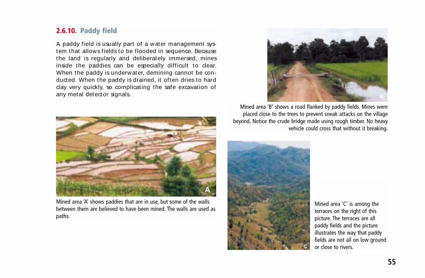
55
2.6.10. Paddy field
A paddy field is usually part of a water management sys-tem that allows fields to be flooded in sequence. Becausethe land is regularly and deliberately immersed, minesinside the paddies can be especially difficult to clear.When the paddy is underwater, demining cannot be con-ducted. When the paddy is drained, it often dries to hardclay very quickly, so complicating the safe excavation ofany metal detector signals.
Mined area ‘A’ shows paddies that are in use, but some of the wallsbetween them are believed to have been mined. The walls are used aspaths.
Mined area ‘B’ shows a road flanked by paddy fields. Mines wereplaced close to the trees to prevent sneak attacks on the village
beyond. Notice the crude bridge made using rough timber. No heavyvehicle could cross that without it breaking.
Mined area ‘C’ is among theterraces on the right of thispicture. The terraces are allpaddy fields and the pictureillustrates the way that paddyfields are not all on low groundor close to rivers.

56
2.6.11. Semi-arid savannah
Defined as having little vegetation, the circumstances thatdeminers face in arid grassland can also be very varied.
Mined area ‘A’ is an area ofsparse grassland that wasmined to prevent the movementof tanks across it. The ground isvery hard and stony, and thegrass never grows more than20 cm high. The small bush thatcan be seen to the right of thedeminer’s head is very toughand can only be easily cut usingwire-cutters.
Mined area ‘B’ is an area of arid grassland around the base of powerlines which were mined to prevent attack. The deminer is checking
how the sensitivity of his detector is affected close to theelectromagnetic lines.
Mined area ‘C’ shows the samepower line. Each pylon was mined,and some areas between themwere also mined.
Picture ‘D’ shows a termite moundclose to the pylon shown in ‘C’.These are common obstacles insome countries. In many places,
deminers have to cope with bitinginsects and venomous snakes.

57
2.6.12. Bush
‘Bush’ is the term used throughout Africa for the light for-est that covers a significant proportion of the continent. Itusually comprises well-spaced trees without dense under-growth beneath. The height of the trees depends on therainfall and the soil quality.
Mined area ‘A’shows bush on theapproaches to areservoir. The areawas mined toprevent attacks onthe water supply.
Mined area ‘B’ is part of a borderminefield. It shows how conditions in
the bush vary according to the season— and also the way that wildlife may
find sanctuary in mined areas. Thepresence of a healthy giraffe does not
prove the area is safe, the bones ofless lucky animals are further inside
the minebelt.
Mined area ‘C’shows an areawhere bush hasbeen reclaimingfarmed land for 20years. The deminerhas just cut thesmall tree he iscarrying out of theway. When bush isgrowing up, thearea between thetrees tends to bedensely overgrown.
Mined area ‘D’ was taken further along the border in the sameminefield as picture ‘B’. The land in these areas is often very irregular,including ravines and massive obstructions like these boulders.


The first metal detectors to be used as mine-detectors weredeveloped for the military. Following military custom, awritten instruction was produced for their use and this pro-vided a ‘standard’ for the users. Since then, other ‘standards’for metal detector use have been developed by organisa-tions that use detectors in their work (such as police, cus-toms and security organisations). The most comprehensiveof these ‘standards’ cover design and manufacturing fea-tures as well as performance specifications/expectations.
3.1. International standards for metaldetectors
In recent years, a need for a metal detector standard that isrelevant to humanitarian demining has been recognised.This need became urgent as detector manufacturers beganto offer products with widely varying capabilities. Today’spurchasers need independently derived and universally ap-plied ‘benchmarks’ to help them select which metal detec-tors to buy.
Because military forces can be directly involved in breach-ing through minefields, some of their needs are shared
with HD, so the existing standards of most immediate rele-vance to HD are those used by military forces. The standarddocuments in this area are the National Institute of Justice(NIJ) Standard 0602.02 (September 2000), and PerformanceSpecification MIL-PRF-23359H (November 1997). The latterhas been widely adopted/adapted for use by the armedforces in countries other than the United States. The ‘Inter-national test operational procedures standards’ (ITOP) wasanother document adopted in 1999 by France, Germany,the United Kingdom and the United States. The Perfor-mance Specification MIL-PRF-23359H and its variations allinclude a detailed specification of military needs that in-cludes many elements that are of no relevance in humani-tarian demining. For example, there are general require-ments that the detectors have a ‘camouflage’ colour, thatthey be hardened against nuclear, biological, chemical(NBC) agents, and that they operate without visible or au-dible emissions. Some performance specifications are notonly unnecessary, but are inadequate for HD. For example,the MIL standard states that a detector should ‘have agreater than 92 % probability of detecting standard metal-lic military mines … and mines containing small metalliccontent’. This level of detector performance is inadequatefor HD. Also, the scope of the MIL standard does not coverthe many variables that affect detector performance so
Chapter 3: Detector standards and detectortest standards
59

60
does not lend itself to adaptation for HD purposes. Simi-larly, the ITOP (which has been adopted by NATO) definesdetection standards and testing requirements from a mili-tary perspective that is only partially applicable to HD andcannot be readily adapted.
The UN’s International Mine Action Standards include astandard for the ‘Test and evaluation of mine actionequipment’ (IMAS 03.40), which outlines basic principlesfor test and evaluation techniques. Being a documentwith wide applicability, it does not provide specific con-tent of relevance to testing and evaluating metal detec-tors, but it does provide a basic template that could beused to build a standard.
3.2. International standards for metal detectors in humanitarian demining
When this book was in preparation, the first agreementover standards for metal detectors in HD was reached.The process began when the European Commission man-dated the European Committee for Standardisation (CEN)
(21) to make progress in standardisation within humani-tarian demining. In response, CEN BT/WG 126 was estab-lished. WG 126 recommended that CEN workshops shouldbe established to work on the test and evaluation of bothmetal detectors and mechanical equipment for use in HD.The international test and evaluation programme (ITEP)(22) also requested a CEN workshop on metal detectortesting and evaluation.
Before European standards are formally adopted, theymust go through a ratification process that can take sev-eral years. However, a CEN workshop agreement is similarto a ‘draft’ standard and can be used pending achieve-ment of a formal European standard. Any European stan-dard on metal detectors that is produced may or may notbe based on the CEN workshop agreement.
The UNMAS has agreed to reference the CEN workshopagreement in its IMAS.
Adoption of the CEN workshop agreement will allow testand evaluation of metal detectors in HD to be made in aninternationally standardised way. Like IMAS documents,the agreement will be subject to revision over time. Theearly adoption of this agreement allows purchasers tounderstand better what they are buying and this shouldincrease safety by ensuring that deminers are using the
(21) The CEN is the European standardisation organisation that establishes common standards for industry and science and of whichalmost all European countries are members.
(22) The ITEP develops standards for testing and evaluating all kind of humanitarian demining equipment.

61
best tools for the job. The CEN agreement also providesmanufacturers with procedures that make it easier forthem to evaluate their own products. CWA 14747:2003(the agreement from CEN workshop 07), was formallypublished on 18 June 2003 (23).
3.3. European Committee for Standardisation workshopagreement (CWA 14747:2003)
The CWA 14747:2003 lists the metal detector tests thatare of greatest relevance in HD. It details how the detec-tors should be tested, so allowing manufacturers to knowwhat is expected from their products. It is hoped that thiswill make it easier for manufacturers to respond to theneeds in HD. The manufacturers will know what theyshould do to characterise their detector’s performance, itsdifferent technical functions, durability, ergonomics, andmaintenance. They will have the added advantage ofknowing the tests that will be applied to their competi-tors’ equipment, and so be better able to estimate the rel-ative success of their products. It is not expected that thiswill result in all detectors becoming the same because theagreement only provides a minimum test and evaluation
regime. Manufacturers can make their detectors do more,and the agreement includes suggestions for additionaltests and specialist goals that are not ‘standard’ require-ments. The agreement specifies the minimum informationthat manufacturers should supply with their products andstates how that information should be derived.
3.3.1. What is covered by the detector testagreement?
The tests are divided into those specified by the user,those carried out in air and in the ground, and field tests(which may be in air or in the ground). Some can only bedone under controlled conditions in laboratories whileothers can only be done in the field. Advice and directionson how to carry them out are given, along with indica-tions of the kind of measurements to be made and howto record and analyse the results.
The tests of detectors carried out in laboratories undercontrolled conditions should be identical in order for theirresults to be replicable and directly comparable. Theresults will provide an overview of technical details andperformance characteristics that makes it easier for aprospective purchaser to pre-select a shortlist of potentialproducts.
(23) CEN workshop agreement, ‘Humanitarian mine action — Test and evaluation — Metal detectors’, CWA 14747:2003, published 18June 2003.

62
Currently, purchasers may have to test many makes andmodels of detector in their working area before they canchoose which model to buy. With CWA 14747:2003 inplace, the purchaser should get enough information tostart to make informed judgements over which detectorsare suitable for the proposed area of use. When coupledwith some of the information given in this book, theauthors believe that end-users will be able to carry out apre-selection that refines possible choices to just a fewmodels (or possibly only one) before any field trials.
The CEN agreement cannot be retrospective, so there willbe no information about many detectors that are in usebut have been superseded in manufacture. This informa-tion may be essential when the end-users are trying todetermine the possible advantages of upgrading themetal detectors they use. At present there are uncon-firmed plans for tests of the currently used detector fleetto be made under the neutral auspices of the ITEP.
The matrix in Annex D gives an overview of the CWA14747:2003 tests. We have designed the structure to aidunderstanding rather than to reflect any internal struc-ture of the agreement itself. Similarly, we have sometimesused naming conventions to assist understanding ratherthan those used in the agreement. Despite these minorchanges, we are confident that the reader will have nodifficulty locating relevant tests in the formal document.
Some of the user and miscellaneous tests are not finely de-tailed. This is because they are intended to cover the users’
unique needs in their own area. For example, the targetsused in miscellaneous tests must match the anticipatedthreat in the area where the detector will be used. It is rec-ommended that such targets include ‘difficult’ mines andcommonly found mined-area scrap metal pieces. The inclu-sion of scrap metal may help the deminer to gain confi-dence about the detector’s ability and detection depth. Itwill also make the deminer familiar with the varied audiblesignals that the detector may make. The combination oftargets used and the ground in which they are concealedwill make each purchaser’s miscellaneous testing unique.Unlike the laboratory tests, the results are unlikely to be di-rectly relevant to a different purchaser in another area.
3.4. Previous metal detector tests in humanitarian demining
Armed forces all over the world have carried out selectiontests in order to decide which equipment to purchase.Anecdotal evidence suggests that commercial interestsmay occasionally have outweighed the interests of theend-users. For example, a particular detector’s perform-ance may have been adopted as the benchmark, whichmakes it unlikely that any other detector would ‘beat’ itin all areas. But in most cases a genuine attempt has beenmade to make an unbiased selection. However, as previ-ously mentioned, the requirements of armed forces arenot the same as the needs in HD.

63
During the 1990s, metal detector manufacturers selling tothe HD market found that there was a demand for someperformance characteristics that had not been needed bytheir military and ‘treasure-hunter’ customers. Using a de-tector for six hours every day, for example, led to a long andreliable battery-life having a high priority. It was no longeracceptable simply to advise that new batteries be used eachtime the detector was used. Despite a relatively small num-ber of potential customers in HD, many manufacturers haveinvested heavily in the refinement and revision of their detectors to meet HD needs. This may be because theyrecognise that a selectable performance level and im-proved ergonomics would also be attractive to their mili-tary market. The commitment and the interest involved indetector development over the past decade leaves the au-thors convinced that a ‘smart detector’ (24) will soon beavailable. In this context, ‘soon’ may be as early as next year.There is already one ‘dual-sensor’ detector (see Annex B,Section B2.8.1, ‘Metal detection and ground-penetratingradar’) combining metal detection with a ground-penetrat-ing radar in military use, and this may be improved and re-fined for appropriate HD use within the next few years.
During the period of rapid metal detector development,formal HD evaluation of some models was carried out inCambodia, Afghanistan, Mozambique and Bosnia andHerzegovina. Most of these field trials made direct per-
formance comparisons between the available detectorsbut the full results were not published. The ‘trials’ becameinternal ‘selection’ procedures and although the resultswere shared informally, the testing itself varied and theresults were often of little relevance to a demining groupworking on another continent.
The Cambodia trials were carried out in the mid-1990s. TheBosnia and Herzegovina trials were carried out in 1997. Tri-als in Afghanistan were carried out in 1999, 2000 and 2002.Preliminary and final trials were carried out in Mozambiquein 1999 and 2000. In each place, the detail of the testingvaried, and in most places, the models of detector testedalso varied. There were many variations in testing proto-cols, models of detector and the way that results wererecorded. Apart from learning from each other about howfield trials should be conducted, the results from each trialcould not be usefully shared. For similar reasons, the resultsof many smaller trials carried out by individual demininggroups cannot be usefully shared with others.
The most sophisticated and expensive series of detectortrials/tests was started by the international pilot projectfor technical cooperation (IPPTC) (25) in December 1998.This was a brave attempt to achieve an objective compar-ison of 29 different models of metal detector and includ-ed laboratory and field tests on three continents. It took
(24) ‘Smart’ metal detector — A detector capable of reducing ‘false’ alarms by providing reliable information about the size, shapeand/or type of metal detected.
(25) Participants — Canada, European Commission, the Netherlands, United Kingdom, United States.

64
21 months to complete the trials and a further eightmonths to publish the results. Some criticisms of the rangeof tests and the models ‘selected’ were made (26) but themajor weakness of the results was the time it took forthem to be made available. Almost three years after thedetectors were selected for test, a whole new generationof untested detectors were already on the market. A sub-stantial amount of time, effort and money had beenspent in an attempt to make it easy for a purchaser tochoose the best detector for his needs, but the value ofthe results was compromised by the late publication.Much of the delay in this project was due to protracteddiscussions about what tests to conduct and how toreport the results. It is hoped that the existence of CWA14747 reduces this problem in subsequent similar trials.
3.4.1. Why so many field trials?
There are several reasons for the rush of metal detectortrials in recent years. Chief among these is the fact thatorganisations in HD subject their detectors to heavy use,and even the most robust usually need replacement everythree to five years. Some HD organisations also updatetheir detectors regularly to improve the clearance outputor the safety of the deminer. In other cases, sponsors,
donors or controlling agencies may have required thatequipment trials be carried out. Whatever the reason forreplacing an old detector, it was the range of new modelsthat dictated that the user should not simply buy more ofwhat he had last time. Without the help of repeatabletests and a standard that allowed the purchaser to predicthow a particular detector would perform, comparativefield trials had to be carried out. Even when CWA14747:2003 has been in use for some time, a purchasercannot accurately predict how a detector will actually per-form in the local ground conditions. This is largelybecause local mined area survey groups have no simpleand scientifically rigorous way of measuring and record-ing those conditions. This problem has been recognisedand research into defining and resolving it is currentlyunder way. In the meantime, CWA 14747:2003 shouldmean that the users only have to field trial a few models.
3.5. The output of humanitariandemining detector trials
Since the trial in Bosnia and Herzegovina (27), all major HDfield trials have had a structure similar to that adopted by
(26) Sometimes detector users did not understand the practical value of the tests, why some of their concerns were not covered, orwhy they included tests of detectors that had never been used in HD.
(27) Full title, ‘Hand-held metal detector trial conducted in the Former Republic of Yugoslavia’, January 1997 (Bosnia and Herzegovina,Sarajevo, Mostar), for the UN Mine Action Centre Sarajevo.

65
CWA 14747:2003. They have involved tests in air, in theground and to meet the specific needs of HD in the area.Over the same period, small demining organisations andinstitutes also conducted independent tests — either forpurchasing detectors or for special research aims. General-ly, the aim was to determine the best overall detector,but this objective was not achieved — possibly because auniversal detector has not yet been made. Most of thewell-known detectors have advantages and weaknesses,performing better and worse than their competitors invaried contexts.
The results were intended to provide an overview of:
(a) the basic detection capability of the detectors;
(b) the detectors’ reaction to the metals used in mines;
(c) what influenced the detector’s signal (28); and
(d) whether it was possible to detect targets in magneticground conditions, and if so, how best to do this.
Tests (a) to (c) are ‘general’ tests while (d) is specific to theuser group’s requirements. This does not imply that (a) to(c) are less important, although the decision over whichdetector to purchase will depend heavily on a positiveresult for (d). This is because in test (d) detectors are test-ed against the greatest threat in the area. In most cases,
this will be a mine with a minimum metal content. Mini-mum metal mines are not always the main cause of civil-ian casualties, but they are usually the targets most likelyto be missed when using a metal detector. It is not possi-ble for an outsider to reliably state which mine will bemost difficult to detect because mines deteriorate in vari-ous ways and may become more difficult to detect withthe passage of time. An example is the GYATA-64, whichhas a large metal content, but can become very hard todetect when the metal corrodes (see Figure 2.3).
The tests of detection capability in air and in the groundare also important. Their results provide a ready compari-son of each detector’s general ability to detect metal, easeof use and ability to work in the relevant ground condi-tions. Most detectors sold for use in HD today have a GCcapability intended to filter out magnetic interferencefrom the ground. Their designers have developed differ-ent technologies to achieve this end. Some detectorsautomatically and constantly search the ground forchanges in the background magnetic ‘noise’ in order tofilter it out. Others have to be manually ‘set up’ to com-pensate for magnetic ground. Still others compensatesemi-automatically with the user applying some proce-dures. The relevant method is described in the detector’suser manual and should be followed strictly. The variousprocesses involved in achieving ground compensationmean that some detectors maintain their detection
(28) See Section 2.3, ‘Using metal detectors in area demining’.

66
sensitivity while others have a reduced detection capabili-ty when in GC mode. A loss of detection sensitivity meansa reduced depth at which targets can be detected.
The sensitivity of some detectors cannot be reduced. Others can be reduced, but this facility must be limited sothat detection capability is never reduced to zero withoutswitching off the detector. An erratic or automatic reduc-tion of sensitivity must be avoided for obvious reasons.The sensitivity tests (a) to (c) will help to reveal a detec-tor’s general strengths and weaknesses.
The tests include other features such as the ability to dif-ferentiate between two targets, to detect along lineartargets (metal fences, railways, gates, etc.), to detect trip-wires, and to determine the shape and position of targets(pinpointing). These special tests may vary for the regionbut they are of great importance in building deminer con-fidence in the equipment.
3.6. Output of the international pilotproject for technical cooperationtrials
The IPPTC trials were the most comprehensive and scien-tifically sophisticated trials of metal detectors to date.New testing equipment was developed and a newapproach towards ease of test replication was adopted,
although some of the trials could only be done with spe-cial measuring instruments that are not commonly avail-able. The following examples briefly describe the IPPTCapproach — from which many lessons have been learnedand many aspects have been incorporated into the CWA14747:2003.
The results of the IPPTC trials were recorded in a neutralmanner and made widely available. The readers of theresults are presumed to have knowledge of detectors andthe ability to analyse the conclusions to meet their ownneeds. Unfortunately, the results had been superseded bynew detector developments even before they were pub-lished. The IPPTC trials began in 1999. By December 2000(when the Mozambique accelerated demining pro-gramme (ADP) trials began), six new or varied modelswere available for inclusion. At the time of writing (threeyears later), the authors are aware of a further six modelsthat would be included in any current assessment.
3.6.1. Tests in air
The following tests were conducted in air and in labora-tories under controlled environmental conditions. Thesame tests could be carried out in the field but theywould be less controlled and environmental variablescould influence the results.
• Calibration test. The calibration test established therepeatability of the detector’s set-up routine. The

67
distance was measured at which a specific targetcould be detected after each detector was set up tothe manufacturer’s specifications. The practical resultsshowed differences between the types of detector,with the distance fluctuating up to 8 cm. These differ-ences could be life-threatening in a mined area if thecheck against a ‘confidence target’ is not done.
• Drift test. The drift test measured the detector’s abil-ity to locate the same target over a 30-minute period.The detector was set up as specified for the start ofthe test, and not adjusted during the test. The resultsshowed a fluctuation of up to 9 cm. Fluctuations ofthis magnitude could lead to mines being missed.
• Moisture test. This test checked whether the pres-ence of moisture on the search-head affected thedetection capability. A detector head may be wetafter rain or when there is dew on the ground (it isnot ‘normal’ for deminers to work in the rain). Theresults showed that the presence of moisture couldreduce the detection distance by up to 11 cm.
• Sweep speed test. This test was to determinewhether a particular speed of detector-head move-ment gave the best detection capability. The resultsidentified the optimum speeds and should also alertusers that the sweep-speed can be important.
• Scan profile test. This was the first time that a ‘scanprofile test’ to determine the ‘footprint’ of a detectorhad been included in any formal trials. A standard tar-
get was used and the magnetic search field was meas-ured at different depths between it and the search-head. The results showed that all the detectors testedhad a crudely conical footprint (widest at the top),although some of the manufacturers have previouslystated that this is not really so. Depending on thedetector, the target and its position, the resultsshowed each detector’s sensitivity in air. The practicaluse of this test is explained in Section 5.4.2, ‘Search-head sensitivity profile (footprint)’.
3.6.2. Tests in the ground
The in-ground tests were intended to establish the detec-tors’ ability to locate standard and other targets at varieddepths and in magnetic ground. Targets were selectedand placed, with detailed records of the time of place-ment and their precise position recorded.
3.6.3. Tests in the field
The IPPTC field tests were carried out in Cambodia andCroatia. After the publication of the results, another testwas conducted in Central America. In each of these tests,varied ground was used to help define the detectioncapability. The conductivity of each ground type wasmeasured vertically and horizontally. The magnetic sus-ceptibility was also measured. Unfortunately, these meas-urements have not provided an answer to the question

68
‘what has direct influence on the performance of thedetector’. This means that, at present, only a test in theplace of use can provide an accurate indication of how adetector will perform there.
Comparing the detection of the same targets in air and inthe ground gave an indication of how severely the influ-ence of magnetic ground could affect performance. Theresults can be summarised as:
• All detectors were influenced by the reactionbetween magnetism in the ground and the detector’selectro-magnetic field. Manufacturers’ attempts toreduce the influence used varied approaches, some ofwhich were more effective than others.
• Some detectors that could not be set up to compensatefor ground magnetism were unable to detect mineswith a minimum metal content in magnetic ground.Some of those detectors could not reliably detect minesin non-magnetic ground at depths of 20 cm.
• Some detectors could be set up to compensate for dif-ficult ground but lost detection sensitivity as a result.
• Some detectors could be set up to compensate for dif-ficult ground while maintaining a normal detectionsensitivity in air.
3.6.4. Miscellaneous tests
The mine action centres responsible for providing supportand personnel for the tests added the miscellaneous tests.The targets were almost all the problem mines (or parts ofthe mines) that were found in the country where the testing occurred.
3.7. Output of other tests/trials
Most other international tests were carried out under the con-trol of (or on behalf of) the UNMAS. In these, groups of spe-cialists carried out tests to determine the detectors’ suitabilityfor purchase for use in UN-directed mine clearance opera-tions. The detectors under test varied from trial to trial but thestructure and content of all the trials was generally similar. Anexception was the test/trial carried out in Mozambique by theUN accelerated demining programme. This test/trial differedbecause it included measuring the detector’s reaction to mag-netic ground (29), and because all the short-listed detectorswere used in different mined areas (‘live’) for several weeks.
The ADP quality assurance team that conducted the testsestablished their own method of measuring the magneticground interference in their varied working areas. The tool
(29) The US army are reported to have used a graded system defining magnetic properties of soil in the 1960s. This knowledge waslost and was not known to participants in the ADP when their test area was devised.

69
used to make the measurements was the most commonmetal detector available to the ADP. It was used because itwas available and because it was a static detector that gavea constant reading when held stationary above a targetand/or magnetic ground.
The detector was set at a particular sensitivity and liftedabove the ground to the level where the audible detectorsignal stopped. See Annex E, ‘Calibration of the SchiebelAN19/2 M7’, for a description of how to calibrate the de-tector before doing this. The distance from the search-head
to the ground was measured. This gave a crudely repeat-able measure by which a magnetic ground interference‘reference’ could be determined. By testing all types of de-tector used by the ADP on ground with measured levels ofmagnetic interference, it was possible to usefully predicteach type of detector’s performance in ground with similarmagnetic properties. Later, using dedicated measuring in-struments, it was confirmed that the ‘reference’ resultsfrom the Schiebel detector were accurate enough to be re-liably used to anticipate the increased detection difficultyas the ground reference height (GRH) increased.
Detectors and ground reference height and GYATA 64
Det
ecti
on
dep
th in
cm
25
20
15
10
5
0
0
5
10
15
20
25
Gro
un
d r
efer
ence
hei
gh
t in
cm
1 2 3 4 5 6Test lanes
Group 1 Group 2 Group 3 Ground ref.
Figure 3.1: Summarised results using a Gyata-64 AP blast mine as the target

70
To carry out the tests, the ADP built protected lanes filledwith varied reference ground in their dedicated trainingarea. This facility was unique at the time, and is still avail-able for others to use. Their results showed a clear linkbetween magnetic ground interference and the depth atwhich targets could be detected.
The left vertical axis shows detection depth in centime-tres. The horizontal axis shows the test lane in which thetarget was concealed. The right vertical axis shows thereversed GRH to illustrate how it affects the detection
ability. Each lane has a different magnetic ground refer-ence, with increased magnetic ‘disturbance’ as you readfrom left to right. See Figure 2.3 for a picture of theGYATA-64 showing its large metal content.
Group 1 comprised the ADP’s preferred detectors, all ofwhich had a GC capability. Group 2 comprised groundcompensating detectors that lost significant sensitivitywhen the GC feature was used. Group 3 comprised detec-tors that had no GC capability.
Detectors and ground reference height and mine type 72a
Det
ecti
on
dep
th in
cm
Gro
un
d r
efer
ence
hei
gh
t in
cm
0
5
10
15
20
251 2 3 4 5 6
Test lanes
14
12
10
8
6
0
4
2
Group 1 Group 2 Group 3 Ground ref.
Figure 3.2: Summarised results using a Type 72A blast mine as the target

71
The graph illustrates the reaction of the detectors to theincreasing magnetic interference in the test lanes. Withthe increase of the magnetic interference, Groups 2 and 3lost sensitivity by around half or became entirely inca-pable of detecting the target (depending on the target’smetal content). A certain stabilisation of performanceoccurred in Test Lane 4, which was defined as the ‘medium’ magnetic ground reference.
The left vertical axis shows detection depth in centi-metres. The horizontal axis shows the test lane in whichthe target was concealed. The right vertical axis shows thereversed GRH to illustrate how it affects the detectionability. Each lane has a different magnetic ground refer-ence, with increased magnetic ‘disturbance’ as you readfrom left to right.
The ADP found the performance of the detectors inGroups 2 and 3 unacceptable when the magnetic groundreference was higher than 8 cm (which was the measuredbenchmark for the third lane (TL 3) in the training area).See Figure 2.3 for a picture of Type 72a showing its smallmetal content.
Since the completion of the test/trial, some detector manu-facturers have used the ADP test lanes for internal assess-ments of their detectors. The ADP continues to use itsmake-shift measuring method to get a crude record ofmagnetic interference during technical surveys because it
allows them to determine which model of detector to usein that area. While it may not be ‘scientifically rigorous’,they are in no doubt that it is useful when planning thedeployment of their detector fleet.
In their test conclusion in 2000, representatives of theADP stated that the:
‘ADP knows of no instrument that measures the level ofmagnetic interference ground reference. Our approachis one simple way, but not a solution. The issue of beingable to measure a ground reference will gain impor-tance when the IMSMA (information management sys-tem for mine action) database is available worldwide. Itwill then become important to have a worldwide stan-dard. Survey can define the ground reference level innumbers and the detectors will be easy to assess againstspecified targets, under equal conditions.’
Later in the IPPTC report’s abstract and conclusions, a sim-ilar statement recommended that mined-area surveyorsshould conduct simple conductivity and susceptibilitymeasurements (30). Specialist equipment to do this doesexist. Called ‘susceptibility meters’, the HD community hasyet to fully recognise their potential value.
While laboratory testing provides a high-level qualitycheck, it cannot cover practical concerns such as how eas-ily the deminers can set up the detector or how much it is
(30) CCMAT Canada carried out measurements of the magnetic properties of the ground before the IPPTC trial.

72
setting ‘drifts’ during real use. Neither can tests in air giveresults that can be used to reliably infer a metal detector’sperformance in real ground conditions. Laboratory testsare invaluable but must still be followed by field trials inthe area of use. After successful trials, deminers shouldalways perform a ‘confidence’ test against a realistic tar-get directly before entering each mined area. This finaltest must always be conducted as close as possible to thearea where the detector will be employed.
3.8. Do current detectors match theneeds in humanitarian demining?
If an experienced deminer were asked, ‘Do the detectorson the market match the needs in the field?’ the usualanswer would probably include, ‘yes’, ‘if’ and ‘but’.
The deminer would only answer ‘no’ when the detectorwas being used at its technical limits. Although work isconstantly ongoing to improve detectors, the work is con-strained by the fact that the effects of varying groundconditions on detector performance are not clearly understood.
A detector’s limitations can be defined by reference tothree performance areas. The first is its ability to detect arange of different kinds of sizes of metal targets. This‘advantage’ may be complicated by the ‘disadvantage’ ofan increased alarm rate if tiny metal targets are thendetectable. The second performance area is the sensitivityor detection depth, which is dependent on the target andthe user’s skills. The third performance area is the detec-tor’s ability to compensate for the magnetic interferencefrom the ground — and the effect the compensation mayhave on the first two.
If manufacturers are to improve their detectors further,more information is needed from the field. It would, forexample, be possible for existing geological data to becombined with information gained during mined-areasurveys, and those data to be included in the IMSMA
Figure 3.3: A Bartington meter formeasuring magnetic grounddisturbance. Notice the waythat it resembles a conventionalmetal detector.

73
database. To achieve this, standard tools and proceduresfor collecting ground samples and magnetic referencedata would have to be agreed. The results would be use-ful for planning the appropriate clearance resources touse in an area, and could also give scientists a better ideaof the range of magnetic ground problems that could beexpected within a particular country.
3.9. Lessons for future tests/trials
Summarised reports of previous detector tests/trials areavailable on various websites. While lacking detail, thesegive the basic test structure and the general conclusionsof the test/trials. Some general lessons that may be of useto anyone planning detector tests/trials can be derivedfrom them. In brief, these are listed below.
1. Begin by clearly defining the aim and objectives ofthe test/assessment — including the type of targetand the context in which it must be found.
2. Select the detectors to test with reference to the aimsand objectives. Narrow down the selection to meetthe particular need.
3. Devise tests that can be repeated in the future — so al-lowing the results to be updated without the need toconduct complete retrials. Be aware of import restrictionsand try to ensure that no restricted equipment is used.
4. Describe the tests and how the data will be collectedand assessed as clearly as possible before starting anypart of the tests.
5. Tell the manufacturers your aims and objectives andask them to advise which of their detectors are mostlikely to meet your needs.
6. Give the manufacturers the opportunity to includeprototype models of new developments in the rangeof detectors for test/trial.
7. Prepare a test area that includes a range of typicalsoil/ground from the mined areas where you will work.
8. Include ‘end-users’ in the testing. Prepare question-naires designed to record the end-user’s opinions onease-of-use, ergonomics, training, durability, etc.
9. Include as many real targets in your test/trial as possi-ble. These should represent the main threat from theareas where the detector will be used. (Rememberthat the ‘main threat’ is defined as the device(s) mostlikely to be missed with a detector.)
10. Be aware that individuals influence results. The resultof the same test with the same detector may varyaccording to the operator. Devise your tests/trials toovercome this by repeating them with as many oper-ators as is practical. Also, before the test/trial, youshould decide how any conflict or contradictions inthe results will be evaluated.

74
11. Define how you will assess the training and mainte-nance package that will be available.
12. Decide how to calculate the potential detectors’ run-ning costs.
13. Establish contacts enabling you to ask other organisa-tions about their experiences with the detectors thatperform well.
3.9.1. Data collection/analysis during fieldtests/trials
Decisions over what data to collect and how to recordthat information should be made at the same time asdeciding the aims and objectives of the test/trial. Thesedecisions should lead to the preparation of simple data-record sheets that will be filled out during the test/trial.The easier the data-record sheets are to understand andcomplete, the fewer mistakes will be made. A well-designed record sheet will require the recorder to fre-quently mark a ‘Hit/Miss’ or ‘Yes/No’ choice that minimisessubjective judgement. The design of the data-recordsheets should also allow easy comparison between record-ed results, such as: the sensitivity in air to the same target;differentiation between two targets; the detection of targets close to large linear metal targets; etc. For consis-tency between trials, distances and depths should bemeasured in millimetres. With enough forward planning,field test/trial data can be measured and recorded by peo-
ple without any special qualifications as long as they payattention to detail.
Depending on the country and the clearance depthrequired, the targets should be buried at several depthsthat reflect the depth of mines actually found. For thesensitivity measurement, the targets should be buried atthe maximum clearance depth required. When measuringa target’s depth, all targets (mines, simulants or surro-gates) must be measured to the top of the target. If tar-gets are placed some time before the test/trials, a checkshould be made to ensure that the depth of each targethas not changed. This check must not disturb the groundin a way that could affect the detectability of the targets.We recommend using a thin, stiff wire to penetrate theground directly above the target, then measuring thedepth at which the obstruction is encountered. Do notplace targets inside plastic tubes in magnetic groundbecause the presence of the tube influences some detec-tors and can make detectors signal (in a similar way tofalse readings from cracks in sun-baked ground). We rec-ommend that small targets are set in a larger resin castingor made a part of a bigger target that is easier to deployaccurately and to find later.
The following information should be collected before andduring the test/trial. More data may be included, but theyare unlikely to affect the result and may confuse theanalysis. If no specialist measuring instruments are avail-able this is unlikely to affect the test/trial results but itmay make them less useful or compelling to others.

75
We recommend that the following general informationabout each test/trial be recorded.
• Ideally, the magnetic ground properties should berecorded so that the test/trial results can be comparedwith those from other tests where the same magneticmeasurements were made. Such a comparison may bemore useful after the completion of further researchinto the way that various ground conditions affectdetector performance, but the data should be gath-ered now.
• Information about the test area, the targets and theirplacement should be noted, including a geo-referencefor the site and details of controls and inspections.
• Fully detail the make, model and year of manufactureof the detectors involved as well as the used targets.
• Record the meteorological conditions in the test area reg-ularly during the test/trial. This should include a record ofthe temperature (or the air and ground), ground mois-ture, humidity, and the wind speed and direction.
• Describe the ground conditions accurately. This shouldvary for lanes that have been made using difficultsoil/ground brought to the test area. Record the vari-ous magnetic properties and include details of howthese measurements were obtained. Record the scrapmetal content (if any), composition, texture, distribu-tion of stones/rock, moisture content and vegetationthat is present for each lane in the test area.
• Record all the test/trial results as accurately as possibleusing prepared data sheets designed for ease of use.
• Describe the conduct of the tests/trials in detail, cov-ering the start/stop times and those requirementsmade in relevant demining group SOPs.
As well as actual performance data, we recommend thatthe following information about detectors be recordedduring the actual test/trials. This will make the subsequentevaluation easier.
• Record any reliability and compatibility events experi-enced during preparation.
• Make a safety assessment of each model, includingergonomic and human health aspects.
• Record the training required before first use, and assessthe ease of training for general use for each model.
• Record any apparent effects of the climate on eachmodel.
• Examine and record any transportation and handlingissues.
• Examine each model for apparent durability andrecord notes on the ‘supportability’ of the equipmentin the field.
After analysis, the data collected should be presented in away that makes them easy to understand. This may be in

76
text, tables, photographs, video, charts, and/or graphs.The data should be described in sufficient detail to enablethe reader to understand the basis for the analysis andconclusions. For more information the reader should con-sult CWA 14747:2003.

This chapter introduces the technology on which currentmetal detectors rely. The principles are explained, andsome of the science is introduced so that you can betterunderstand why the metal detector is the most commonlyused detection tool in demining. A better understandingof why detectors work can significantly increase safetyand efficiency.
4.1. How metal detectors work
This section explains the principle of electromagneticinduction.
When a metal detector is switched on, an electric current ispassed around the windings of a coil which is contained inthe search-head. Electric currents always produce mag-netic fields, that is to say, they can exert a force on iron(and certain other materials) and can align a compass nee-dle, just like an ordinary magnet or the natural north–southfield of the earth. (31).) The expression ‘magnetic field’means an area of space where there is a magnetic effectwith significant strength, pointing in a definite direction.
The magnetic field generated by the current flowing in thesearch-head is called the ‘primary magnetic field’. The direc-tion of the field is along the lines, which are called ‘lines offlux’, shown in Figure 4.1. The strength of the field is pro-portional to the density of the lines of flux. The field isstrongest near to the wires of the coil where the lines of fluxare concentrated, and the direction of the field is so that thelines of flux make loops around the wires of the coil.
(31) The generation of magnetic fields by electric currents was discovered by H. C. Ørsted of the University of Copenhagen in 1820 anddeveloped in detail by D. F. J. Arago and A. Ampère in Paris in the same year.
Chapter 4: Metal detector technology
77
Figure 4.1: The primary magnetic field of a metal detector

78
The electronic circuit of the detector is designed to pro-vide the current in the coil either in the form of pulses orin the form of a smoothly varying wave. In both cases thecurrent repeats, usually at between 1 000 times and50 000 times a second. As a result, the magnetic field ofthe metal detector varies rapidly in time as well as inspace — which is unlike the field of any ordinary magnetor the magnetic field of the planet itself.
The laws of electromagnetic induction (32) state the following.
1. A time-varying magnetic field induces an electric volt-age which is proportional to the rate of change of themagnetic flux.
2. The induced voltage is in a direction, positive or neg-ative, so that it opposes the change that produced it.
Metals conduct electricity. This means that electric cur-rents flow in them when an electric voltage is applied.
When a piece of metal is put in the changing magneticfield of a detector’s search-head, the following happens.
(a) If the metal is magnetic (such as ordinary mild steel),it will become magnetised. The magnetised metal willproduce its own magnetic field.
(b) Whether or not the metal is magnetic, the electricvoltage induced by the changing magnetic fieldmakes currents flow around in the metal (followingthe first law of electromagnetic induction). The cur-rents tend to flow around the lines of flux in patternslike eddies in a river, so they are called ‘eddy cur-rents’. The eddy currents also produce their own mag-netic field.
For both reasons, metal objects generate a ‘secondarymagnetic field’. It spreads out in space and reaches backto the wires of the coil in the search-head. This secondaryfield varies in time along with the primary field. Again,according to the first law, an electric voltage is theninduced in the coil. Following the second law, this voltagewill tend to oppose the efforts of the circuit to vary thecurrent.
An electronic circuit measures the induced voltage in thecoil. This voltage consists of a fixed part, induced by theprimary magnetic field, and a part induced by the second-ary magnetic field which only occurs when a metal objectis present. The circuit is constructed to sound an alarmwhen the induced voltage rises above a chosen threshold.The threshold is adjusted until the detector remains quietin the absence of metal and signals only when metal ispresent.
(32) The first law of electromagnetic induction was discovered by M. Faraday of the Royal Institution, London, in 1831 and the secondlaw by H. F. E. Lenz of the St Petersburg Academy of Science, in 1833.

79
The primary field is shown in blue, and the secondarymagnetic field produced by a small metal object, in black.
The strength of the secondary field will depend on theproperties of the object. In general, on the surface of theobject it is of the same order of magnitude as the primaryfield. In Figure 4.2, the black secondary field flux lines areshown more concentrated than the blue primary field fluxlines, to make the shape of the fields clear.
4.2. Electromagnetic properties of materials
To discuss this topic, we pose some questions that are fre-quently asked and then give answers.
Are all metals magnetic?
No. Some metals are (mild steel, cast iron) and some arenot (aluminium, copper, brass).
Do all metals conduct electricity?
Yes. However, some metals have quite low conductivitywhich makes them more difficult to detect, especially if theyare also non-magnetic. See Section 4.6 for details of how theelectromagnetic properties of materials are quantified.
Can metal detectors find both types of metal?
Yes. In a magnetic metal, both magnetism and the flow ofeddy currents generate a secondary magnetic field thatcan be detected. In a non-magnetic metal, only the eddycurrent mechanism operates. But in all types of metal, asecondary magnetic field is generated and therefore ametal detector can find them.
What are ferrous materials?
Ferrous materials are materials which contain iron. Thisincludes all kinds of steel and cast-iron and iron-bearingminerals like magnetite and haematite.
Figure 4.2: The presence of a secondary magnetic field

80
Are all ferrous materials magnetic?
No. Some stainless steel alloys (usually with a large percentage of chromium) are almost completely non-magnetic in spite of containing a large percentage ofiron. These are often called ‘austenitic’. Austenitic alloysare sometimes used in mines and can be hard to detectbecause they also have quite low conductivity.
Are all magnetic materials ferrous?
No. Apart from iron, some other elements which can besignificantly magnetic are nickel, cobalt and manganese(these elements may be alone or in compounds). Forexample, the copper-nickel alloys used in some coins aremagnetic.
Are metal detectors affected by materials which donot conduct electricity?
Yes. They can be affected by materials that are magneticbut do not conduct electricity. A familiar example is ordi-nary rust. Such materials do not support eddy currents butdo generate secondary magnetic fields and can make ametal detector signal. This is important because iron oxideand other magnetic minerals occur naturally in some soilsand rocks and can affect metal detectors even when thereis no man-made metal debris present.
4.3. Metal detector working principles
The principle of electromagnetic induction is common to allmetal detectors but there are many variations in the way itis used. A substantial number of patents (33) have been filedand each manufacturer advocates the advantages of theirparticular technical approach. It is wise to view claims oftechnical superiority sceptically because good quality in-struments using quite different working principles areavailable. It has not yet been established which, if any, ap-proach is really the best. In any case, the practical merits ofa particular detector will not rely solely on its working prin-ciple. The experience of the designers with certain types ofcircuit or coil can be very relevant, as can the availability ofgood components or the ease of manufacture.
4.3.1. Pulsed induction versus continuous wave
In all metal detectors the magnetic field must vary intime. This may be achieved either by generating it in theform of short pulses with periods between where the cur-rent is zero (Figure 4.3), or by varying smoothly in theform of one or more sine waves (Figure 4.4).
Some pulsed induction metal detectors are: Ebinger420GC, Guartel MD8, Minelab F1A4 and F3, Schiebel AN19(PSS12), Vallon 1620 and VMH2. Some continuous wave
(33) See the survey by Sigrist and Bruschini in Annex F, ‘Suggested further reading’.

81
Figure 4.3: Magnetic field measured from a Vallon VMH2 detector
This is a pulsed induction detector with a bipolar field, having a 370 Ìs pulse width and 225 Hz repetition frequency.

82
Figure 4.4: Magnetic field measured from a Foerster Minex 2FD 4.500 detector
This is a continuous wave detector employing one sine wave signal at 2 400 Hz and another smaller one at 19 200 Hz.

83
metal detectors are: CEIA MIL D1, Foerster Minex 2FD andEbinger 420SC.
4.3.2. Frequency-domain versus time-domain
In frequency-domain detectors, the circuit measures theinduced voltage as sine waves of one or more individualfrequencies. Both the amplitude (the height of the sinewave) and the phase (the extent to which the inducedvoltage sine wave lags behind or leads the current wave)may be measured.
In time-domain detectors, measurements are made at cer-tain times after each pulse. The direct effect of the pri-mary magnetic field occurs within the first microsecond orso but the secondary magnetic fields may last for tens ofmicroseconds. The detection circuit reads the coil voltageafter the effect of the primary field has died away, whenany remaining voltage is due to the secondary field, forexample, at 35 microseconds. In many designs, the receivecircuit is switched off completely during the pulse, toavoid being swamped by the strong effect of the primarymagnetic field.
Time-domain detectors always have pulsed fields. Fre-quency-domain detectors usually have continuous wavefields, but may not always do so. A frequency-domain
detector can be constructed with a pulsed field becauseany periodically repeating signal can always be brokendown into a sum of sine waves of different frequencies(34). So equivalent sine waves can be extracted even froma pulsed field detector and it can be made to work in thefrequency-domain.
4.3.3. Single coil versus separate excite/receivecoils
In some detectors, the induced voltage is measured acrossthe same coil that is used to produce the primary mag-netic field. In others, it is measured across a separate coil.For example, the Schiebel AN19 has two concentric coils,one to excite and one to receive. By contrast, the Ebinger420GC uses a single-coil search-head design.
4.3.4. Static and dynamic modes
When a detector search-head is held still above a metal ob-ject and the alarm sounds continuously, the detector isworking in ‘static mode’. In ‘dynamic mode’ detectors, thealarm turns off after a few seconds because the circuit com-pares the induced voltage with its value a few seconds earlier and only sounds the alarm if the voltage has changed.
(34) This is a mathematical fact which is true of all sorts of phenomenon, not just electromagnetic fields. It was discovered in Greno-ble in 1807 by Jean-Baptiste Joseph Fourier, who was working on heatwaves.

84
Both modes have strengths and weaknesses. Dynamicmode can help when working in the presence of someconstant background disturbance, such as alongside ametal rail or fence or when attempting to locate a smallAP mine in the vicinity of a large metal-cased AT mine.Static mode allows the operator to move the search-headvery slowly without missing the mine and is sometimesthought simpler to understand.
The Guartel MD8, Minelab F1A4 and Vallon detectors aredynamic mode detectors. Static mode is used in the Foer-ster Minex 2FD 4.500 and Schiebel AN/19. A recent versionof the Ebinger 421GC detector allows the operator toselect between static and dynamic modes.
Some very simple dynamic mode detectors actually have astatic primary magnetic field and rely on the movementof the search-head to generate the time variation, butthis type of design is not used in high-sensitivity instru-ments of the quality required for demining.
4.3.5. Single receive coil versus double-D(differential) receive coils
In some detectors, the receive coil is split into two D-shaped halves, one of which is ‘backwards’, so making ashape like . The two halves are connected in such a waythat the voltage induced in one is subtracted from thevoltage induced in the other. The detector signals whenthere is a difference between what is ‘seen’ by the two
halves of the receive-coil, and this is why it is called a ‘dif-ferential design’.
Because differential coil detectors respond to the differ-ence between the properties of the objects sensed by thetwo Ds, they do not respond to factors that influenceboth sides of the coil equally. This means that they are rel-atively insensitive to the magnetic properties of theground itself when those properties are evenly spread.
As the search-head passes over the object, the detector sig-nals when the metal is under one D, goes briefly silentwhen the metal is equally under both Ds and sounds againwhen the metal is under the other D. The metal can be lo-cated with some precision using the position of the ‘null’between the two Ds. This design allows superior pinpoint-ing of a target but at the price of ‘blind-spots’ in front ofand behind the entire search-head. However, these blind-spots mean that the design can also be used beside rails andmetal fences. If the detector search-head is swept parallelto a linear metal object, with the line dividing the twohalves of the coil perpendicular to the object, both sides ofthe coil will be affected approximately equally and thepresence of a rail or fence can be cancelled out.
So it is important that double-D search-heads shouldalways be swept from side to side. If it is used by movingthe search-head back and forth in a push-pull movement,this could lead to missing mines in the blind spots.
The double-D design is used in the CEIA MIL D1, FoersterMinex 2FD and Guartel MD8 detectors.

85
In Figure 4.5, the top of a PROM-1 bounding fragmenta-tion mine can be seen in front of the search-head. Themine is just to one side of the centre line, in the null area.If the detector is used correctly, by sweeping from left toright, the mine will be detected when it is nearer one Dthan the other. If it used incorrectly, by sweeping forward,the mine could be missed, or even activated.
4.3.6. Bipolar pulse versus unipolar pulse
In pulsed-induction detectors, the pulses can be ‘unipolar’or ‘bipolar’. A unipolar pulse means that the pulsed cur-rent in the coil only flows in one direction. A bipolar pulsemeans that in alternate pulses the current flows in oppo-site directions (as in Figure 4.3). With bipolar pulses, theaverage current (and therefore the magnetic field) overmany pulses is zero, but it is not zero for a unipolar pulsetrain. This may be relevant for those who feel concernover the risk that the small constant magnetic field pro-duced by metal detectors could trigger a magnetic influ-ence fuze.
A demining organisation must decide whether or not it issafe to select a detector with unipolar pulses. Activationof magnetic influence fuzes by metal detectors is a theo-retical possibility but has not been a recorded cause ofaccidents in humanitarian demining (36). Magnetic influ-ence fuzes are used in a minority of AT mines and somebooby traps, but they have a limited field life and the fewthat are known to have been found during humanitariandemining have been ‘inert’ (with dead batteries). In theopinion of the authors, it is acceptable to use a detectorwith a unipolar field in an area where the risk-assessmentis that active magnetic influence fuzes are unlikely to befound.
(35) Photo courtesy of F. Littmann.(36) This has not been the cause of any incidents recorded in the DDAS.
Figure 4.5:A Guartel MD8 search-head (35)
86
4.3.7. How are metal detectors designed for demining different from other types?
Metal detectors are used in many other applicationsincluding the body-search of persons (either as walk-through or hand-held), for treasure-hunting, for pipe andcable detection and on industrial production lines. Thecoil (search-head) size and shape are dictated by theapplication.
The effective range of a detector depends to a largeextent on the diameter of the coils used in the search-heads. Detectors with bigger coils have better detectioncapability at greater distances. This raises the question:why do not all detectors have large coils in their search-heads? The main reason is that the sensitivity of thedetector to small objects is reduced by making the coillarger, so a 1 m-diameter coil would not be able to find asmall mine even if it was not far below the surface. This isbecause the large coil spreads the magnetic field over awide area, so the local field intensity is reduced.
So there is a trade-off. All other things being equal, a de-tector with a small coil will show a relatively high detectioncapability for metal objects that are close to it, but a poorlong-range performance. Detectors with larger coils gener-ally have a better detection capability at distance, butpoorer detection capability for nearby metal objects. Thereare two other reasons why large coils would be unsuitablefor detecting small mines. Interference from magnetic orconducting ground (see Section 4.5) is proportionally
greater for a large diameter coil and it is also harder to pin-point a small mine with a large coil. The diameter of a de-mining detector coil is usually around 20 cm and that of aUXO detector coil about a metre.
Access to the place to be searched may also affect thechoice of coil. Demining detectors usually have flat coils, either circular or elliptical in shape. The Guartel MD8 has anoption for a cylindrical wand coil for use in narrow gaps.
Design of detectors is a trade-off between cost and quality factors: sensitivity, effectiveness of ground com-pensation and electromagnetic interference suppression,reliability, weight, balance, ease of use, robustness andbattery life. Those designed for treasure-hunting are simi-lar in layout to demining detectors, and may have groundcompensation, but are usually much cheaper and not assensitive, robust or well-made. Some treasure-huntingdetectors are fitted with visual displays. These are undesir-able in demining detectors because it is important not todistract the deminer from visual clues on the ground.
4.3.8. What is important from the user’s point of view?
As explained above, there are considerable differences inthe details of how metal detectors are designed. From theuser’s point of view, some of these differences matter alot more than others. Whether a detector is frequency-domain or time-domain, has a single-coil or separate

87
receive-transmit coils does not change the practicalitiesvery much, if at all. On the other hand, a detector with adouble-D coil behaves very differently from one with asimple circular coil and it is dangerous to confuse the two.Similarly, a detector that operates in static mode behavesvery differently from one that operates in dynamic mode.Accurate pinpointing cannot be achieved unless the oper-ator is aware of these things. Training should emphasisethose factors that really matter to the deminer with adetector in his hands.
4.4. Suppression of electromagneticinterference
Electromagnetic interference (EMI) arises when a signalfrom an external source induces a voltage in the detectorcoil, making the detector signal without metal being pres-ent. It is also possible for the detector’s electronics to beaffected directly by an electromagnetic signal, rather thanvia the coil. A detector affected by electromagnetic inter-ference will often make a sound which is obviously differ-ent from the signal it makes when it is has detected metalin normal use.
The main EMI sources are:
• high-voltage power lines and substations;
• radio transmitters;
• electric motors;
• other metal detectors.
Some detectors are equipped with filters to suppress radiosignals and signals with the frequency of electric powertransmission (50 Hz in Europe and most of the world,60 Hz in the United States and a few other countries).Some detectors allow selection between 50 and 60 Hz fil-ters. EMI suppression is important in humanitarian demi-ning because it may be necessary to work close to electricpower lines, radio masts or industrial facilities in circum-stances where it is inconvenient or impractical to arrangeto have them switched off.
Metal detectors will only interfere with each other if theyare close together, but the interference distance variesfrom 1 and 20 m depending on the detector model. Whentwo different models of detector are brought closetogether, it is possible that only one of the detectorswould be affected by the other.
Some detectors such as the Vallon VMH2, CEIA MIL D1and Minelab F1A4 have circuits which can be adjusted orsynchronised to allow two detectors to operate on differ-ent channels, so that they do not interfere with eachother. Interference between detectors is not a routineproblem in humanitarian demining because deminers usu-ally work at a safety distance from each other of 25 m.Interference between detectors becomes a safety issuewhen a deminer has been injured but his detector is stillswitched on. A rescue team must then approach the

88
casualty using another detector before carrying out anevacuation.
4.5. Ground compensation
One of the main limitations of metal detectors is that theycan be affected by the ground itself, which limits howhigh the sensitivity of the detector can be adjusted. Thishappens because the ground also conducts electricity tosome extent and can also be magnetic. The same mecha-nisms that allow the detector to find metal may also makeit respond to the ground. It is also relevant that while themetal components of mines are often very small, theground fills all the space under the search-head. So evenwhen the ground’s electric and magnetic properties aremuch weaker than those of the metal, they can still com-plicate detection.
Metal detector manufacturers have devoted a great deal ofresearch and development effort to overcoming this prob-lem. High-quality modern detectors are equipped with spe-cial systems called ‘ground compensation’ (see p. 20) cir-cuits which reduce their sensitivity to the ground withoutreducing the sensitivity to metal very much. Except in thevery best of detectors, however, there may still be some re-duction in sensitivity to metal when used in GC mode.
It is usually necessary to make a preliminary adjustment tothe ground conditions in the place where the deminers areworking. This typically involves holding the detector in theair and moving the search-head down to the soil whilst either activating an automatic learning sequence using apush-button or adjusting the circuit manually using a dial.Ground compensation procedures generally vary betweenmodels of detector, so particular attention should be paidto the details given in the instruction manual.
Ground compensation in a time-domain detector can beachieved by identifying a characteristic decay time for theground and programming the receiver circuit so that thealarm does not sound when the detector encounters atarget with this particular decay time. In most cases, thedecay time for ground is shorter than that of all but thesmallest metal objects, so the detector can reject theground signal without missing metal items unless they arevery small (Figure 4.6). Because of this, any pulse induc-tion design which samples a few tens of microsecondsafter the pulse automatically has a degree of ground com-pensation. In severe cases, however, where the decay timeof the ground is long, sensitivity to metal will be reducedif the detector is adjusted to reject the ground signal. Oneway to get around this is to use current pulses of differentlengths (37). These can give rise to different decay times inthe same object. It is very unlikely that the ground andthe metal object will have the same decay time for all
(37) Bruce, H., Candy, US Patent 5 537 041 (1996).

89
pulse lengths so the circuit can be programmed to distin-guish the ground signal and reject it.
Ground compensation in a frequency-domain detectorworks in more or less the same way. The detector identi-fies the phase-change of the signal, i.e. the time lag ofthe induced signal behind the current (Figure 4.7) and isadjusted to ignore signals with the phase-change charac-teristic of the ground. To avoid rejecting metal by mis-
take, additional variables can be introduced by usingmore than one sine-wave frequency, which is rather likeusing variable pulse lengths in a time-domain detector.
If the signal is sampled after about 20 microseconds, thesoil signal in this case is negligible. Even better groundcompensation can be achieved by measuring the decaytime of the signal and/or using excitation pulses of differ-ent lengths.
Simple time domain detector signalsSi
gn
al (
arb
itra
ry u
nit
s)
Time/micro-seconds
-20 -10 0 10 20 30 40 50 60
Coil current
Mine signal
Soil signal
1.2
1
0.8
0.6
0.4
0.2
0
Figure 4.6: Soil and mine signals in a time-domain detector

90
If the receiver is set up to reject signals of a certain phase(i.e. which lead the current by a certain fraction of awave) the soil signal in this case will be ignored. Even bet-ter ground compensation can be achieved by using two ormore frequencies.
The double-D coil design gives a degree of suppression ofground effects automatically because the ground is under-neath both Ds and the signals from the two approximatelybalance out. It is not completely effective because, if theground is not exactly flat, the amount under each D may be
Simple frequency domain detector signals
Sig
nal
(ar
bit
rary
un
its)
Time/micro-seconds
Coil current
Mine signal
Soil signal
1
0.8
0.6
0.4
0.2
0
-0.2
-0.4
-0.6
-0.8
-1
0 100 200 300 400 500 600
Figure 4.7: Soil and mine signals in a frequency-domain detector

91
different. The ground properties may also vary from pointto point and so be different under one D to under the other.
‘Noisy’ or ‘uncooperative’ magnetic ground is common. Ahigh proportion of iron oxide or other ferrous minerals inthe ground is often the cause. Red clay soils such as the‘laterite’ of Cambodia and Angola, and the bauxite soilsof the Dalmatian coast of Croatia are examples. Groundwith the black iron-bearing mineral magnetite may alsobe ‘noisy’. However, the presence of magnetic mineralsdoes not always give rise to a long decay time and theexact conditions that affect metal detector use are stillthe subject of research. What is known is that a combina-tion of high electrical conductivity and high magneticeffects is the worst situation of all.
Exposure to high temperatures by burning may adverselychange the ground properties. Volcanic minerals may alsoaffect detectors. Individual stones and rocks may give sig-nals even when the soil itself does not. Conversely, the soilcan give signals but contain rocks which do not — a situ-ation that is also undesirable because the properties willthen vary from point to point. Ground which is verysaline, for example on a beach, may conduct electricityunusually well and so may make a detector signal as if itwere metal.
4.6. How the electromagneticproperties of materials are quantified
4.6.1. Conductivity and resistivity
Some metals conduct electricity better than others. This isimportant because, in general, the better the metal con-ducts, the easier it is to detect. Soils and water also con-duct electricity but nothing like as well as any metal.
The electric conductivity of a material can be expressed as anumber which measures how much current a piece of thematerial conducts, allowing for its size and shape and whatvoltage has been applied to it (38). It is expressed in ‘siemensper metre’, written S/m or S m -1. Some people prefer othernames: ‘per ohm per metre’, which is written ø -1 m -1, and‘mho per metre’, but they all mean the same thing.
Resistivity is the opposite of conductivity. It describes theability of the material to resist the flow of electrical cur-rent. To calculate it, just divide 1 by the conductivity. It isexpressed in ‘ohm metres’ written ø m. For example, highpurity copper has a resistivity of:
1 ÷ 59 x 10 6 S/m = 1.7 x 10 -8 ø m (0.000 000 017 ø m)
(38) A formal definition is, ‘the current per unit cross sectional area per unit electric field’ (the electric field is the gradient of the voltage). See Electromagnetic fields and waves: including electric circuits by P. Lorrain, D. Corson, F. Lorrain, W. H. Freeman, 3rdedition, 1988 — ISBN: 0-716-71823-5.

92
To avoid such very small numbers, some people expressresistivity of metals in ‘micro-ohm centimetres’ or µø cm.1 µø cm = 10 -8 ø m.
4.6.2. Magnetic susceptibility and permeability
The simplest way to describe the magnetic quality of amaterial is to use a measure of its ‘relative magnetic per-meability’. This is a measure of how much the materialmagnifies the effect of the magnetic field. For steel, thiscan be as high as a few hundred times. For non-magneticmaterials (and for air), the ‘relative magnetic permea-bility’ is 1. Because it is just a relative scale, there are nospecial units to remember.
Materials which are very slightly magnetic have a relativemagnetic permeability just slightly greater than 1. It isthen often more convenient to use the difference from 1,which is called the ‘système international (SI) magneticsusceptibility’ (39).
Example: A particular soil has an SI magnetic susceptibility of0.002. Its relative magnetic permeability is 1 + 0.002 = 1.002.
4.7. Factors that affect detection
Modern metal detectors are extremely sensitive deviceswith the capacity to detect small amounts of metal.
(39) Système international — the international system of measurement units that has been adopted worldwide. We note that the SIconvention is used here because there is an older unit system known as the ‘cgs’ or centimetre-gram-second system. In the ‘cgs’system the susceptibility is also just a scale factor (scientists call such quantities ‘dimensionless’), but its values are different fromthe values in the SI system.
Table of conductivity values for various materials:
Pure silver 61 million S/m
High purity copper 59 million S/m
Aluminium 40 million S/m
Lead 4.8 million S/m
Stainless steel 1 to 1.75 million S/m
Graphite 130 000 S/m
Silicon 0.3 to 15 000 S/m
Sea water 3 to 5 S/m
Freshwater 0.001 S/m
Wet soil 0.01 to 0.001 S/m
Dry soil 0.0001 to 0.00001 S/m

93
However, it is worth remembering all of the factors thatcan influence detection capability when a metal detectoris used in a real situation.
4.7.1. The metal object or ‘target’
The characteristics of a metal object govern whether ornot it can be detected. The size of a target is important,but more important is its shape and orientation withrespect to the detector coil. Objects are easier to detect ifthe detector can easily generate eddy currents in themetal.
For example, a complete ring of metal parallel to thedetector coil is much easier to detect than a broken ringor loop which currents cannot circulate around. Turning aring so that its axis is perpendicular to that of the coil willreduce the signal it produces in a metal detector. So aPMN mine (see Figure 2.3) with its large metal ringaround the rubber top will be an easy target when lyinghorizontal. If the same mine is placed on its side, detec-tion will be more difficult.
In the past, detection capabilities have been expressed interms of the mass of metal detectable. Without any defini-tion of the shape and orientation of the metal object, this isnot a helpful approach. One gram of aluminium in the formof a flat foil parallel to the detector coil is much easier todetect than a gram of aluminium in the form of a very thin,long pin with its axis parallel to that of the coil.
The metal from which the object is made also has an important effect. As previously mentioned, metals withhigh conductivity are easier to detect than those with lowconductivity, and magnetic metals are easier than non-mag-netic ones.
4.7.2. Distance between the detector’s search-head and the metal object
The strength of the magnetic field produced by the metaldetector diminishes with distance from the coil, as can beseen clearly in Figure 4.1. Similarly, detection capabilityreduces rapidly the further a metal object is away fromthe search-head. At three or four coil diameters, even verylarge metal objects do not trigger a signal.
The interplay between the target characteristics and thedistance at which it can be detected is the normal way ofdefining detection capability. In particular, people use themaximum height in air or maximum depth in the groundbeneath a detector’s search-head at which a given targetcan be detected.
The detection capability is not constant at all points under asearch-head. Small metal objects at a given depth may onlybe detected when located precisely on the coil axis. But alarge object at the same depth may produce an alarm whenthe detector coil is some distance to the side of the object.
To measure this spatial variation in detection capability, asensitivity profile (footprint) measurement is often made.

94
Figure 4.8 shows one way in which such measurementscan be presented. A detector has been swept from side toside over a metal target, moving the search-head forwardbetween each sweep, so producing an area scan. Theaudio signal from the detector alarm has been recordedand plotted for each point in the scan as a colour corre-sponding to the signal strength. Dark blue indicates a lowor zero signal. Red indicates a high signal strength. Thescan has been repeated with the target held at three dif-ferent depths below the detector coil and the results havebeen plotted together.
At 20 mm below the detector, the signal is very strongover a circular area of about 300 mm in diameter underthe detector coil. At 110 mm below the detector, the sig-nal strength is reduced and it is clear that maximum signalonly occurs in the centre of the footprint, on the coil axis.At 200 mm below the detector, the target gives only avery weak signal.
For all detectors, the sensitive area of the footprintalways gets smaller as depth increases. This variation withdepth is often described as a sensitivity or detection‘cone’. For different detectors, the patterns are slightlydifferent, particularly for those with differential designs,but the basic principle is the same. It is very importantthat users are aware of this effect. For example, imaginethat a detector is being used to search for a target at adepth at which it is only just detectable (in a small area onthe coil axis). The search-head needs to be moved forwardbetween sweeps in steps small enough to ensure that the
high sensitivity ‘spot’ covers all of the ground. If thesearch-head is moved forward by too large a step (movingforward by a set distance is often a ‘rule’) the mine mayeasily be missed.
An alternative way of presenting the sensitivity profile isin diagrams showing contours defined by the limiting caseof detection for particular targets. Figure 4.9 shows anexample of this approach, with the contours for three dif-ferent targets, 3, 5, and 10 mm-diameter steel balls. Atthe detector settings for which the diagram was
Figure 4.8: False-colour sensitivity profile at three different values ofthe detector height above a metal target (Minelab F3 measured atJRC, Ispra)

95
produced, the target can be detected within the contourbut not outside it. The contours for the 10 mm and 5 mmballs show that the maximum detection depth is achievedon the coil axis. At a given depth, it is possible to estimatethe width of the region over which these targets can bedetected.
In the case illustrated, the maximum detection depth forthe very small (3 mm-diameter) ball is under the windingsof the coil rather than on the coil axis. For some detectors,it is noticeable that the most sensitive region at very close
range does occur under the windings. This fact is some-times used in the procedures for locating very small metalobjects that are close to the ground surface.
Diagrams showing detection limit contours can be pro-duced for any section through a detector coil. For exam-ple, plots of the contours in a horizontal plane (parallel tothe coil) are often made. For a method of determiningthe profile of a detector for a target while in the field, seeSection 5.4.3, ‘Determining a field-accurate sensitivity pro-file (footprint)’.
4.7.3. Ground properties
In demining operations, the ground properties will oftenhave an influence on metal detectors. For simple detec-tors, this may require the sensitivity to be reduced toavoid signals from the ground. Even if ground compensa-tion functions are used, the detection capability may bereduced. This means that for a given target the maximumdetection depth can be reduced, sometimes significantly.Another way of expressing this is that at the area underthe detector giving the required detection, capability canshrink, or even disappear.
One important aspect of such ‘noisy’ ground is that it isoften heterogeneous, that is the ground properties varyfrom place to place. This heterogeneity may be caused,for example, by magnetic stones in a relatively benignsoil, or by non-magnetic stones in a magnetic soil. The
Figure. 4.9: Schematic view of a sensitivity profile on a sectionthrough a metal detector coil showing contours of detection limits for 3, 5 and 10 mm steel balls

96
ground compensation methods of some detectors copewell with this. Other detectors have problems with suchsituations. One example of such heterogeneity is thecracking that can occur in dried earth. Some detectors(notably some differential designs) have been known tosignal on such cracks.
The fact that some detectors can give a signal from cracksor other voids in magnetic ground may actually help theirdetection capability in some situations. A buried minimummetal mine displaces a volume of soil and replaces it withmaterials that for the most part have no influence on ametal detector so can be considered as a void in mag-netic ground. The apparent ‘void’ may make a detectorsignal. However, relying on this phenomenon for detectionis not recommended!
4.8. Metal detectors, radar and radiowaves
The electromagnetic fields used by metal detectors arenot quite the same thing as radio waves. Radio waves arethe result of another law under which a changing electricfield generates a magnetic field — almost the mirrorimage of the first law of electromagnetic induction statedabove. The effect of the two laws working together isthat the electric and magnetic fields sustain each otherand can spread out to huge distances, which is why radio
is an excellent means of communication. But this can onlyhappen if there is an antenna big enough to support thewave at the start of its journey. How big an antenna isneeded depends on the ‘frequency’ of the signal. The ‘fre-quency’ is the number of times that it is repeated eachsecond. The lower the frequency, the bigger the antennanecessary. To broadcast a significant amount of radiopower at the frequencies used in metal detectors wouldrequire an antenna hundreds of metres long. A metaldetector search-head is too small to broadcast much radiopower and the electromagnetic fields it generates are ofa different kind (called ‘near-field’) which have a re-stricted range, at most a few times the diameter of thesearch-head. It is possible to transmit radio waves of higherfrequencies up to hundreds of millions of times a secondfrom a small antenna suitable for use as a hand-heldmine-detector and this is exactly what happens in aground penetrating radar detector.

Well-planned and executed training can have a profoundinfluence on self-discipline and safety in mined areas.Demining is inherently dangerous and, when using ametal detector in a mined area, the deminer will face thatdanger on his own. A deminer’s training must be goodenough to mean that he always acts safely regardless ofwhether a supervisor is watching. Because deminers arehuman, they will forget detail and can even forget to becautious. Nothing is more dangerous than a deminer whois overconfident or begins to believe that he is somehowimmune to danger.
A training inadequacy was identified as a possible causein more than 20 % of the accidents recorded in the data-base of demining accidents (DDAS) (40).
Here is a short example of extended experience leadingto over-confidence. The UNADP, Mozambique, has alow mine accident rate despite having about 380 sur-veyors and deminers working in mined areas. In 1999,for the first time in five years, a UNADP deminer had anaccident while excavating a detector reading. About ayear later, a second deminer initiated a mine with aprodder. Both deminers had excellent records and hadworked as deminers for more than four years. They had
become over-confident and had begun to break estab-lished rules as they worked. The cause of the accidentswas identified and refresher training was improved. Atthe time of writing, more than three years have passedwithout any further excavation accidents.
Ongoing training can bring people down to earth and re-mind them that there are sensible rules they have to follow.A mine does not respect experience. It treats soldiers, civil-ians, diplomats, animals, journalists and deminers in thesame way. Despite the dangers inherent in mine clearance,adequate training and appropriate caution can make it rel-atively safe. In professional demining organisations, manymore staff are the victims of traffic accidents and diseasethan of accidents with explosive ERW.
5.1. Deminers and their basic trainingrequirements
People who choose to become deminers often have noother way to earn a living. Humanitarian mine clearanceusually begins immediately after the end of a national
(40) A searchable collection of accident reports and inquiries authored by Andy Smith, published by the GICHD and available on CD.Contact [email protected]
Chapter 5: Training
97

98
conflict which may have gone on for decades. During theconflict, the people will have had little opportunity to geta formal education or enter a career path other than assoldiers. So it is not surprising that immediately after theend of a conflict many deminers will be ex-soldiers. Some-times they are recruited as a deliberate policy to reducethe number of ex-soldiers who are unemployed and seenas a threat to peace.
Many demining organisations like to recruit ex-soldiers.The structure of demining organisations is often similar tothat of the military and both require firm discipline, so awell-trained soldier can be an ideal deminer candidate. Astime passes after a conflict, fewer ex-soldiers are availableand more civilians are recruited. The job is attractive tocivilians because it usually pays a relatively high wage (forthe area) and generally inspires respect from the community. Most of the people recruited have few skillsor qualifications that would enable them to get otherjobs commanding respect.
The qualifications needed to become a basic deminer arenot high. Good general health, hearing and sight are theonly physical requirements. Any specific skills and qualifications are a bonus and may help a person gain rapidpromotion. Depending on the employer, people with goodeducation and leadership skills can get further training andmove into supervisory, survey, training or management roles.
While a deminer need not be well-educated, he mustlearn to be competent with the tools he relies on. Most
are low-tech, such as tools for excavation and vegetationcutting. The only hi-tech tool he must master is his metaldetector. A deminer who wanted to become a surveyorwould usually have to learn to use computers, GPS (Glob-al Positioning System) and total stations (theodolites) forminefield mapping and documentation. Others mightaspire to specialising in communications equipment, med-ical support or logistical support where other hi-techequipment is used.
Well-established country demining programmes generallyhave some kind of career path allowing a deminer toadvance. Smaller organisations often do not. Globally, theaverage age of the basic deminer is below 30. The
Figure 5.1:A typical range of deminingequipment that a deminer mustlearn to use

99
deminer’s life in the field is often hard with few luxuries.He must be prepared to spend extended periods awayfrom home and family. It is not surprising that many moveinto other occupations after acquiring saleable skills oramassing some savings.
A basic deminer training course should last about four to sixweeks (the authors are concerned by the fact that manysmall organisations reduce this). The most important partsof the training cover the technical skills needed to use theequipment and the safety rules that must be applied. Thistraining involves the inculcation of drills that should be-come ‘automatic’ so that everyone knows what they (andothers) should do. Examples of such drills are the investiga-tion of a metal detector reading, what to do when a mine isfound, and how to respond to an accident in the minefield.
5.2. Training in the use of metaldetectors
This section deals only with the training that is directlyconnected with metal detectors and the detection ofERW. It does not attempt to cover other training needs inhumanitarian demining, but some of the approaches maybe applicable to broader training needs.
Although a deminer’s training is not extensive, someparts are critical. Appropriate training in the use of their
metal detector can save their life, so should be as simpleand direct as possible. If it is unnecessarily complicated, itcan cause confusion and result in mistakes being made.Most of the manufacturers of modern detectors under-stand the importance of making the detector easy to use.Many of the latest models are designed to limit the pos-sibility of deminer error, or of the deminer reducing sen-sitivity to a dangerous level. Many are supplied with botha manual and a summarised ‘field-card’ that shows themain features of the detector and its use. The manufac-turers often use pictures to carry the message on the‘field-card’, so avoiding language problems. Increasingly,the manufacturers include a CD-based training course.Unfortunately these courses are usually in English (or an-other European language) and the computers needed toshow them are not always available. The manuals arealso usually in a European language. Many deminers donot read and write easily in their own language so, if theinstructions are complicated, the user is unlikely to dis-cover how to get the best from the detector. From hisknowledge of the manual, the field-card and his addi-tional instruction, the deminer must be able to work in-dependently in a mined area. It is not enough to know asimple drill. A change in the environmental conditions orthe variation from one mined area to another can meanthat the deminer must adjust the detector appropriately.The training must give the deminer full knowledge ofhow to use the detector in all the possible clearance situ-ations that he may be confronted with. It must also givehim complete confidence that he knows everything thathe may need to know.

100
5.3. Recommendations for trainers
When a group is purchasing a number of detectors,responsible manufacturers usually provide a package oftraining, maintenance, and spares with their delivery.Under this arrangement, the manufacturer’s staff willtrain the deminer trainers. In a few cases, the manufac-turers take over the training of actual deminers. This isnot ideal because it means that the expensive outsiderswould have to return each time that new deminers needto be trained or when refresher training is needed. Ideal-ly, the manufacturer’s staff will instruct the deminer train-ers and should provide them with a clear explanation ofthe technical attributes of the detector and how best touse it.
While this gives the deminer trainers a good background, itshould not be simply passed on to the deminers. The reasonfor this is that the manufacturer’s trainer will not have beena deminer. He will usually have very limited knowledgeabout the trainees, the areas where the detector will beused, and of the working routines of those who will use it.The deminer trainers should use the manufacturer’s train-ing as a starting point. From the very beginning they shouldthink about what they will adopt from this training, whatthey will leave out, and what must be added to adequatelyprepare the deminers for their work. The deminer trainershould consider the types of targets to be used, the differ-ent ground conditions in the area of responsibility andother environmental conditions that may influence the de-
tector. If he has prepared a list of these considerations inadvance, he can ask the manufacturer’s trainer for adviceand training recommendations.
5.3.1. Self preparation
Before the first practical lessons with deminers, we rec-ommend that the trainer completes the following. Thetrainer should spend at least one day using the detector:
• getting completely familiar with the detailed set-upand specific functions;
• practising setting the detector up to locate selectedtargets in the ground;
• determining the maximum detection depth of themain threat in the area;
• checking for possible EMI that might arise whenworking (from fences, railways, power lines, workingradar and radio stations etc.);
• practising pin-pointing with different targets (point,linear, and polygon targets).
5.3.2. Trainee assessment
First it must be determined whether the training is aimedat experienced deminers (experienced with a different

101
detector) or for new trainee deminers who have not usedany kind of detector before.
New deminers (without field experience)You, the trainer, must allow time to introduce the conceptof metal detection and how a detector works. The trainershould consider very carefully what details to cover andwhat may be interesting but could confuse the deminer.In addition to an introduction to the technology, thetrainees must learn all the things that are describedbelow. Do not explain the difference between this detec-tor and others because they do not need to know thisand it may simply confuse them.
Experienced deminersWhen the trainees have previous experience with anotherdetector(s) the main differences between the old and thenew should be covered. Concentrate on the following points.
Working principles — static or dynamic detector. If thenew detector works on a dynamic principle and the previ-ous detector worked on the static principle, the trainingwill take more time than when the change is from dyn-amic to static.
NB: A dynamic detector can only signal the presence ofmetal if the detector head is moved above the metal. Astatic detector can signal the presence of metal withoutmoving the detector head.
Depending on the length of time that the trainees haveused their old detector, it will take them more or less time
to get accustomed to any new version. When changingfrom static to dynamic, the deminer must understand thatwhen a dynamic detector is held stationary over a targetit will stop signalling. If the deminer was previously welltrained, his use of the detector will have become habit-ual. He will want to hold the detector head over the sig-nal and change the height to help find the centre of thereading. To break this habit and establish a new one,allow extra training time in safe areas.
The sensitivity — in terms of the ability to detect a spe-cific target at depth. The trainer should know the newdetector well enough to answer any questions clearly. Heshould demonstrate the real ability of the detector in dif-ferent places under different conditions so that thetrainees start to want this detector instead of the previousmodel. If the experienced deminer ends up saying, ‘I wantmy old one’, either the trainer has failed or the newdetectors were poorly selected.
The detector signal(s) — the varied signals that a detec-tor can make in the presence of a target are almost asimportant as its sensitivity. People with a ‘musical ear’ andsome technical understanding may get far more informa-tion from the variety of signals than just an indicationthat metal is present. Some detector manuals include adescription of the sounds that may be made but we havenot yet seen a manual that included actual recordings.This is unfortunate because recordings would be of realhelp while training and be of great assistance to thosetechnical advisors without genuine hands-on experience.

102
The way the sounds vary with the targets can be used tomake the training interesting. A simple competition canbe devised to engage interest and gain better perform-ance from the deminers (this is known to have workedwell in some organisations). Deminers with a natural flaircombined with field experience can become extremelygood at interpreting the sound made by their metaldetectors. Even beginners can progress beyond simply‘target’ and ‘no target’ and this raises their self-confidence. As a minimum, the deminer should learn touse the signal to differentiate between targets that are‘point’, ‘linear’ and ‘polygon’ shaped.
Other ‘special’ signals — as well as signalling on thepresence of metal, detectors may make a sound to givethe user confidence that the detector is working. The‘confidence tone’ is usually made at regular intervals andmay be called the ‘confidence click’. Some manufacturessay that their detector’s internal controls are so foolproofthat a ‘confidence tone’ is not needed. Most detectorsalso have one or more warning sounds to indicate thatsomething in the detector has ‘failed’. The sounds warn-ing of detector failure must be recognised before thedetector is relied upon, so it is important that they arefamiliar to the user. There are usually two warning tones,one of which is the ‘battery low’ signal that warns theuser that the detector can only work adequately for a lim-ited time. The second warning sound indicates thatanother failure has occurred and the detector is not func-tional. The batteries may have become too close toexhaustion for the detection circuit to operate or there
may have been a failure in a component. In most casesthe ‘failure tone’ is a continuous signal that cannot beturned off without switching off the detector. Any othersignals will be explained in the manual and the deminersshould be familiar with them all. The ‘failure tone’ signalsoccur very rarely, so most deminers will not hear themunless they are included in their training. During everytraining and refresher course, the trainer should make thedeminers familiar with the sounds and ensure that theyknow how they should react. It may not be necessary tostop work immediately when a ‘battery low’ warning isheard, although most demining groups either replace bat-teries early or stop as soon as there is a warning of lowbattery capacity. When other ‘failure tones’ are heard, it iscritical that the deminer stops using the detector immediately.
To simulate a ‘battery low’ situation during training,either use old batteries, a mixture of old and new batter-ies, or follow the instructions in the manual. To simulate adetector ‘failure’, it is often possible to unfasten the cableor connection to the search-head. Do not forget that ifthe batteries are not connected to the electronicunit, the detector will not signal at all.
5.3.3. Structuring your training
It will take less time and thought to structure trainingappropriately if you are familiar with the detector (Sec-tion 5.3.1) and know the group to be trained (Section

103
5.3.2). Two general rules may be worth mentioning. Thefirst is that repetition is important so that the use of thedetector becomes habitual, so generally you should notchange the exercises covered without good reason. Thesecond is that it is a good teaching principle to progressfrom the general to the detailed, moving from simple tomore complicated points. We recommend the followingtopics to be covered.
1. Introduce the general components of the detector(assembly and disassembly).
2. Demonstrate the working principle (static or dynamic).
3. Set up the detector to find varied targets in differentground/soils.
4. Demonstrate detection signals and allow time forlearning signals. Use different visible targets (point,linear, polygon-shaped with small and large metalcontent).
5. Demonstrate all possible warning signals.
6. Show the maximum detection distance with the tar-gets in-air and in-ground (use FFE mines as targetswhen possible in order to help build confidence).When the trainees are deminers experienced withanother detector, show the comparative advantagesof the new detector. It may be appropriate to com-pare the in-air detection performance with the testresults from comparative trials (such as the IPPTC).
7. Explain the area of sensitivity under the search-head(sometimes called the ‘sensitivity profile’, ‘footprint’or ‘sensitivity cone’). Understanding the footprintarea is essential if the user is to cover the completesearch area in sensitivity range and clearance depth(see Sections 4.7.2 and 5.4.3).
8. Teach how to pinpoint the targets — demonstrate thedifferent ways and train the deminers to do it in theway that is most efficient with their detectors (seeSection 5.4.8).
9. Organise a small competition in which the traineesfind the targets (use FFE mines if possible). Althoughtime penalties may be appropriate, be careful not toturn the competition into a race.
Additional personnel and logistical support — Whenthe structure and content of the training has been de-cided, it is necessary to decide what personnel and techni-cal support will be needed to carry it out. Bear in mindthat every trainee should be kept busy all of the time.Decide how many detectors and other tools are required.Estimate a time schedule remembering that the smallerthe group of trainees, the more intensive the training canbe. Estimate transportation needs, food and accommoda-tion requirements and any additional manpower that willbe needed. Remember that communication and medicalsupport staff will be required at the site.
The preparation of the training area — This is themost important part of the preparation. Prepare the sites

104
in a way that allows optimal and varied training. Trainingshould take place in training lanes and in simulatedmined areas (which may sometimes be the same places).When training areas close to real mined areas are select-ed, this can make it easier to access FFE mines to use astargets. By planning carefully, it may be possible toeconomise on movement from one place to another whilestill giving the trainees experience in different groundconditions. Use a variety of training sites and a range oftargets to increase competence and confidence. It is notas important that experienced deminers do their trainingclose to real mined areas as it is for novices, but it isalways useful.
5.4. The training content
The authors cannot attempt to cover the detailed use ofall the different makes of metal detector. The trainer musttake those details from the relevant user manual. Ourobjective here is to give generic advice on detector train-ing. To do this, we will concentrate on special targets andunusual situations that require special skills and experi-ence. Other useful information can be found throughoutthis book, and especially in Chapter 2, ‘The role of detec-tion in humanitarian demining’.
When devising the training areas, the trainer must use hisimagination to provide exercises that are as realistic as
possible. Some of the exercises described later in this sec-tion can only be done close to real objects (railway orelectrical supply lines). Others such as target proximityexercises can be simulated. Still others may never occur insome countries and may be omitted. The list covers thebasic requirements but the trainer should consider theworking area and alter them or add other exercises asappropriate. Crucially, the trainer should always study allavailable accident reports (with all demining groups) andensure that relevant lessons are incorporated.
The way in which each aspect of the training is actuallyconducted should reflect the normal working practiceswithin the demining group so that good minefield behav-iour is reinforced.
The first contact between the deminer and the detectorwill be during their training. The trainer should try tomake the introduction like ‘love at first sight’. Some willlike the colour, the shape, the sounds it makes. But if thetrainer has difficulty getting it out of its case and assem-bled or has other problems preparing it for use, this willgive the deminers a bad first impression. That will meanthat the trainer must overcome the bad impression duringthe training, so adding to his work.
The introduction to the parts of the detector and itsworking principle can be done with the trainees in largegroups when convenient. All the other activities listed inSection 5.3.3, ‘Structuring your training’, should be carriedout in small groups. The smaller the group the easier it

105
will be for the trainer to ensure that every deminerunderstands and has plenty of time for hands-on practice.The trainer must be sure that all the trainees understandfully and should allow questions to be asked at any time.He should answer those questions as carefully andpatiently as possible in order to bring all of the trainees tothe same level of understanding and competence. By reg-ularly changing between demonstration, questioning, dis-cussion and then practise, the trainer can maintain thetrainees’ concentration. Whatever the teaching style, thetrainees must have the opportunity to practise finding thedifferent targets as often as possible. They shouldprogress from targets laid on the surface to targets con-cealed below the ground, from big targets to smaller upto the limits of the detector. At the end of the trainingthe trainee must be confident that he will find the targetsat the required depth in every mined area. To achievethis, the targets used must include FFE mines or crediblesimulants hidden at the maximum required clearancedepth.
NB: The trainees may be allowed to excavate targets intraining lanes without following excavation drills. How-ever, whenever training takes place in a simulated minedarea, the targets should always be excavated followingapproved excavation drills.
The correct use of the equipment should become ‘auto-matic’, so the training should include a large element ofrepetition. This can be disguised by repeating similar prac-tical exercises in different simulated search-lanes.
5.4.1. Assuring trainee competency
To achieve full competency, the training must go beyondthe ability to determine whether a target’s shape is ‘point,linear or polygon’. It should cover how to decide the safedistance to advance the detector search-head on eachsweep, how to discriminate between two targets closetogether, and how best to exclude interference frommaterials or electromagnetic fields that may be around.Such disturbance may result from the properties of min-erals in the ground, or man-made devices such as radios,power lines or radar stations. Some of these disturbancesmay be rare but if there is any chance of them occurringthe training should cover what a deminer must do whenthey happen. Our experience is that the ‘unusual’ canhappen with surprising frequency, especially if the de-miners are unprepared for it!
The training should cover all situations that are knownand that could realistically occur within the region(s)where the trainees will work. It should always cover thesituation where there are two mines (or signals) closetogether.
5.4.2. Search-head sensitivity profile (footprint)
Knowing about the detectors and their working principlesis not enough. It is essential that the user fully understandthe footprint, sensitivity profile or cone beneath the detec-tor head because this is the area that is actually searched.

106
Assessment of the sensitivity profile (footprint) was intro-duced in the IPPTC detector tests (41). The detection areawas scanned at different heights from a target and theresult for every metal detector using current principleswas a crude ‘cone’ shape.
The data for the following drawing were taken from theADP international detector trial showing average figuresfor four metal detectors (the ‘best’ ones). For demonstra-tion purposes, we have used the simplest illustrationavailable.
Expressed simply, the length of the cone depends onthree things:
1. the model of detector in use;
2. the sensitivity setting necessary to search successfullyfor a specific target, or the sensitivity achieved afterusing the ground compensation facility (when available);
3. the metal content of the target.
It is known that other factors also influence the cone, butto a lesser extent. For example, the influence of theground can be important. You can find the original explan-ation of ground influence on the ADP tests in their finalreport on the ITEP website (42).
The drawing shows the way that a detector’s footprintvaries according to the target and its depth. Determiningthe footprint for a particular target allows you to knowhow far you can safely advance the search-head on eachsweep without missing that target at the establisheddepth. If the GYATA-64 cone is 250 mm long you can seethat at a 130 mm clearance depth the area covered byeach sweep is more than half the size of the search-head.That means that the deminer may safely move his detec-tor half a search-head forward on each sweep — as long
(41) See http://demining.jrc.it/ipptc/index.htm or http://www.itep.ws(42) See http://www.itep.ws, click on ‘Reports’ and in the search area insert ‘Final Report’.
Figure 5.2: Example of sensitivity cones for two specified mines

107
as the required clearance depth is only 130 mm. If hemoves it more than this, he will miss some areas.
Figure 5.2 shows that to achieve the same search-head ad-vance when looking for the much smaller target (Type 72a),it would be necessary to remove 70 mm from the top sur-face of the ground. This is because the Type 72a would haveto be no deeper than 60 mm to ensure detection whenmoving the search-head forward by half its width. In thiscase, it would not be enough to move the search-head for-ward in very small advances because the profile shows thatthis mine could not be found at the required depth.
Failure to understand the importance of the sensitivityprofile (footprint) may explain why some mines havebeen missed in the past. Many groups do not determinethe search-head footprint even when they do check thedetector’s ability to find the target at the required depth.Failure to do this means that users cannot be certain thatthey are advancing at a safe rate.
Here is a way to train deminers to understand the sensi-tivity profile.
1. Measure the maximum detection distance of your tar-get in air (doing this in ground beside the workingarea is described later in this section).
2. Make a sketch with the search-head length/diameteras the base-line and draw a line from the centre ofthe base lane extending the length of the detectiondistance.
3. Join the ends of the base-line to the maximum detec-tion distance. The result is a pointed cone. While thisis a ‘simplified’ profile, it errs on the safe side.
4. From the centre of the base-line, measure along themaximum detection distance to the required detec-tion distance, and draw a line parallel to the base-linethat meets the sides of the cone. The length of thatline is the footprint for that target at your givenclearance depth.
5. Decide the possible advance of the search-head withevery new sweep, which should be less than the foot-print to allow an overlap.
This method works with most detectors but can be diffi-cult if the detector works in dynamic mode or has a double-D search-head and the ground is very magnetic.
It has already been stressed that it is always best to test thedetector’s effectiveness in conditions that are as close aspossible to those in the working area. This is not possibleduring demonstrations of detection theory and introduc-tions to assessing the detector’s capabilities, but nothinggives deminers more confidence than personal experiencein a realistic setting. After the first mine has been success-fully detected using the correct sweep-advance, you can of-ten see the confidence of the deminer increase. When ademiner has done one sensitivity profile he will never forgetit. Confident that he understands the detector’s abilities andlimitations, he will be very careful to ensure that he coversthe entire clearance lane with the detector’s footprint.

108
Using the explanation above, the trainer should getgroups of two to four trainees to produce a more accu-rate detector search-head sensitivity profile (footprint) forfield use. The working principle of the detector has aninfluence but it is quite easy to do accurately for staticand dynamic mode detectors.
5.4.3. Determining a field-accurate sensitivityprofile (footprint)
This section describes how to define the search-head sen-sitivity profile (footprint) in length and width using thesearch-head on realistic ground.
Set up the detector to the ground as described in Section6.2, ‘Adjusting for different ground’. A place free of veg-etation with a sloping hole must be prepared. The holeshould be deep enough for the search-head to be pre-sented horizontally to the vertical wall of the hole asshown in the drawing below.
If the detectors are adjustable to the local conditions, thedetector should make no noise or other disturbance whenin place as shown above.
Now the target/mine should be held in the same orienta-tion to the search-head as it would be if it were beneath theground and the search-head were being used to find it.Move the target/mine parallel to the centre of the bottomof the search-head. Start close to the search-head and move
the target away in 20 mm increments. Mark the placewhere the detector signal becomes uncertain or ends. Thisis the maximum sensitivity depth. Now, scratch a ‘centre-line’ on the ground from the centre of the detector head tothe maximum depth. Move the target towards this fromone side, marking the place where the detector signal be-gins. Repeat this at 20 mm intervals, moving the targetfrom each side towards the centre-line. Make a mark eachtime the detector starts to signal. The marks you makeshow the limit of the sensitivity area. Turn the detectorsearch-head 90° and repeat. You must turn the detectorhead to allow for different search-head geometry.
The outline you have marked on the ground will be closeto a cone. It will be specific to the target, so the smallesttarget mine expected in the area should be used.
To show how the cone varies according to the metallic sig-nature of the target, repeat this again using a larger
Figure 5.3: Determining the search-head footprint in the field

109
target. With large targets such as UXO, the cone mayextend beyond the sides of the search-head.
When several deminers are collaborating to do this test, itshould be repeated with each deminer taking a turn tomove the target and to define the place where the signalstarts/stops. Slight differences will occur but the generalshape should not change.
5.4.4. Discriminating adjacent targets
The trainees must know the detector’s discrimination limits,and how to pinpoint readings that are close together in thebest way possible. This should be practised from two direc-tions, extending and contracting the distance between thetargets. In this way the deminers will not only be told thelimitations, they will experience them and so will be confi-dent about the point at which two signals merge into one.As in other aspects of the training, it can help to concen-trate the minds of the trainees if the trainer explains thepossible consequences of getting it wrong. In this case, thetrainer should explain how two devices close together mayboth explode if one is initiated. This could dramatically in-crease the risk of severe injury even if the deminer is wear-ing very good protective equipment.
5.4.5. Stacked signals
In many theatres, there are instances when a large ATmine has a much smaller AP mine (or mines) placed above
it. If the AT mine has a metal case its large signal can eas-ily mask the smaller signal from the AP mine(s). Similarly,it is also common for AP blast mines to be laid aroundfragmentation mines or their tripwires. The trainer shouldset up examples so that the trainees experience the limi-tations of the detector and so know when there may besignals that have been missed and can excavate withappropriate caution.
In these situations it can be advantageous to use a detector with a double-D search-head. By keeping thecentre-line of the search-head directed towards thestronger signal the user can stop it making the detectorsignal. The signal from the smaller mine can then befound by sweeping the search-head from side to sidewhile keeping the centre-line towards the large signal.
5.4.6. Linear metal targets
Sometimes there are conditions that the deminer has toclear alongside linear metal targets such as railways,metal fences, concrete walls reinforced with steel, pipesand pipelines, etc. The training should include examplesso that the trainees learn the limitations of the detectorand how close they can reliably work. The targets shouldbe FFE examples of the mines in the region or crediblesurrogates because the detector’s ability will vary depend-ing on the target. Only by training in a way that closelymirrors reality can the trainer prepare the trainees appro-priately for what they will find when they work.

110
5.4.7. Electromagnetic disturbance
Detectors may be influenced by electromagnetic wavesthat are transmitted by different sources. Electricity sup-ply lines are commonly mined by both sides in a conflict,so are a common source of disturbance. Other sourcesmay be radio or radar stations. The electromagnetic dis-turbance may make the detector signal constantly, butmay cause them to compensate for the disturbance and solose sensitivity. A mine that was easy to locate at therequired depth outside the influence of the power linemay become impossible to detect beneath them. Thetrainer must ensure that the trainees know how thedetector will react and what they should do. More impor-tantly, the trainees must know what they should not do.
5.4.8. Pinpointing targets
Pinpointing the source of the detector signal increasesefficiency and safety, but the accuracy of pinpointing isnot just dependent on the deminer’s skills. The metal con-tent of the target, the particular detector, and the opera-tor’s ability all affect the potential for accuracy. In labora-tory conditions a well-trained technician may achieve anaccuracy of a few millimetres but it may not be realistic topinpoint with an accuracy greater than 40 mm with thesame detector in the field. This level of accuracy is usuallystill acceptable because it is within the radius of the small-est mine. A double-D search-head can increase pinpoint-ing accuracy for reasons described in Section 4.3.5, ‘Single
receive coil versus double-D (differential) receive coils’.With other detectors, approaching from each side is usu-ally enough to allow the centre of the target to be deter-mined as shown below.
Figure 5.4: Pinpointing: (a) with normal search-heads; (b) with double-D
It should also be remembered that a mine may give morethen one signal. This can be because the metal content isspread out within the device. For example, the PMD-6anti-personnel blast mine has a large fuse and detonatorat one end and small hinge pins at the other. A gooddetector may define both ends as separate indications.Deminers with experience of the PMD-6 can often use thesignals to tell the mine’s orientation beneath the ground,which can make the excavation approach safer. This is onereason why it is important for deminers to know themetal configuration in the mines they must deal with.Most mines have their metal parts close to each other. Inmost cases they are either concentrated in the centre, passthrough the centre, or extend outward from the centre.

111
Only a few are ‘offset’, but these include common minessuch as the PMN-2. When deminers know that the metalmay extend to the furthest side of the mine, they canunderstand why it is essential to start an excavation a safedistance from the reading.
5.5. Work in ‘prepared’ and ‘unprepared’ areas
In this context, a ‘prepared’ area means a dedicated train-ing area in which all of the possible detector signals willbe on targets that were deliberately placed. The area mayinclude lanes using varied ground samples brought fromother places and with targets that have been placed forextended periods of time. An ‘unprepared’ area moreaccurately reflects the general conditions that will befound in the mined areas. Often close to a real minedarea, it will contain natural scrap metal, undergrowth andobstructions. The trainer must also hide targets at record-ed depths, so some preparation is still necessary. Theexperience that the trainees get in the unprepared areasshould provide a bridge linking the artificial training areaand the real mined areas.
The training in prepared areas should be used to coverthe reaction of the detector to all the content listed in theprevious section. The trainer will need to spend less timeover preparation in unprepared areas but there are real
advantages to having well prepared permanent trainingareas. In both, the trainer should start with visible targetsand progress to the detection of buried targets at a depththat shows the limit of the detection ability.
At all times, the trainer should remember that therequirements of experienced deminers are different fromthose of inexperienced newcomers. When the trainees areexperienced, it may be appropriate to limit the work onprepared areas and move to unprepared areas morequickly. The area will contain realistic scrap metal andhave ground conditions that closely resemble those in themined area. If the trainees are newcomers, or if the newdetector’s abilities vary considerably from the old, moretime should be spent in a prepared training area practis-ing detection, pinpointing and determining the depth ofa target. Of course, all relevant SOPs regarding mined-area actions must be enforced during the training. Forexample, targets should be excavated as if they were‘live’. This helps to reinforce other aspects of deminertraining and avoids the trainees adopting bad habits.
The lanes in a prepared area can be set up with a widerange of different targets at various depths in variedground so that in each lane the trainee has a new chal-lenge. This allows the range of potential problems to bepresented very quickly. But training lanes in a preparedarea are essentially artificial and the trainees will under-stand that they are learning how to find targets — notmines. Inexperienced trainees will find the transition toan unprepared area more challenging, and not just

112
because there are additional scrap metal targets. Experi-enced deminers will know that they are safe and may findthe transition less challenging.
When selecting and establishing an unprepared trainingarea, the trainer should select the site long before thetraining is scheduled to start. This will allow targets to beplaced and ‘settle in’ so that their position is not obvious.If time is limited, it may be appropriate to disturb theground in many places where targets are not placed. FFEmine targets (or credible surrogates) should be positionedin a pattern that is known from real mined areas. Addsome details from personal experience, such as boobytraps, UXO (also FFE, of course), tripwires, stakes andother mined-area ephemera so that you will keep thetrainee’s concentration high for the first day at least. Letthem experience what it is like to cut vegetation and findnothing more dangerous than scrap metal later in thetraining. It is essential that newcomers experience this sothat they realise how often they will investigate scrapmetal before they find a real explosive target. Do not for-get to ensure that each trainee experiences situationswhere targets with a large and small metal content areclose together.
It is a mistake to make experienced deminers bored, so donot keep them away from their work longer than necessary.On the other hand do not release them into a live area be-fore you are sure that they are properly trained to copewith all situations that may arise. The experienced de-miners may feel that they know all they need to very
quickly, so the trainer should stress that adequate trainingfor one situation may be dangerously inadequate for an-other. Give examples from recorded accidents when possi-ble, and ensure that the trainees understand the signifi-cance of the more difficult exercises they have to do. It maybe appropriate for us to observe that, if the training is notcomprehensive, the deminers will need more ‘refresher’courses when they move to different working areas.
5.6. Rescue/evacuation using metaldetectors
Trainers must always keep in mind that, no matter howgood the training, accidents will occur and deminers mustbe prepared to cope with them.
We hope that no readers will ever be involved in the res-cue of an injured person from a live area. The situation israre, but the need does arise. The most common case iswhen a civilian is injured by a mine and deminers arecalled to evacuate them. Methods for doing this shouldbe covered in the demining group’s SOPs. When theinjured person is a deminer, it is possible that his detectorwill still be switched on and functioning. This is rare, butthere are several recorded examples in the DDAS.
In humanitarian demining, detectors are generally used ata distance of at least 25 m from each other in accordance

113
with the UN’s International Mine Action Standards. Theonly situation in which detectors may have to work veryclosely together is when a person must be rescued from amined area. This is not because two deminers approachthe victim with detectors, but because the victim’s detec-tor may be switched on. In the worst case the victim’sdetector is pointing towards the rescuers.
Because this is the ‘worst case’, it is the one that the train-ing should cover. In most cases, only one type of metaldetector is available to the rescuers and this will be thesame model as that used by the victim. This is bad becauseboth detectors will operate at the same frequency and somay interfere with each other at distances of up to 20 m,depending on the model. Newer designs sometimes havea ‘noise cancelling’ capability designed to eliminate inter-ference between detectors, and this may work reasonablywell. If the demining group uses different models ofmetal detector, a test should be done to determine theminimum interference distance between them. In somecases this may be as low as 0.75 m which would allow thevictim and other detector to be removed from the areawithout a problem. This should be demonstrated to thetrainees.
To establish the possible working distance between thesame model of detector, simply switch them on, set themto their highest sensitivity and listen to the noise theymake as they are moved closer together. Hold the detec-tors in the air with their detector heads facing each other.When the noise changes, their distance apart is the closest
that they can be safely used. This test will result in a‘worst case’ safe distance. In reality, the detectors areunlikely to be facing each other and may not be adjustedto maximum sensitivity. However, remember that an acci-dent is a stressful situation and the deminer using thedetector may not be thinking as clearly as usual. He maywant to work too quickly and be unable to make a clearjudgement, so the rules should protect them. This is oneof the situations where everybody should carry out thedrill automatically and in accordance with their training.
Usually, it is the closest deminer(s) who must go to theaccident site with a detector and the field supervisor. Thetrainer should set up a worst case simulated accident inwhich the victim has fallen into the mined area with hisdetector. The victim’s detector is switched on and pointingtowards the rescuers. There is no easy way to approach itsafely or to pull it out. The trainer can vary this, creatingdifferent and complex situations but must never forget todemonstrate the solutions.
A possible solution is to always have another model of de-tector on site and have this written into the SOPs. Anotheris to use a hook and line (perhaps a fishing line) to try to re-move the detector. Depending on the safe distance for de-tector use, it may be possible to begin the approach andthen use a long stick with a hook to reach the detector. Ofcourse, whatever method is used should not further endan-ger the victim by risking detonating another mine. Whenno dedicated equipment is available, the trainer should im-provise using whatever is available on site.


After deminers have learned how to use a metal detector indifferent situations they are theoretically ready for em-ployment in mined areas. If their trainer has used the advicein this book, the deminers should be confidently able to usethe detector in all predictable situations, and should beclear about when it is not safe to use the detector.
What follows are two examples intended to show howdeminers work, and how they rely on their detectors. Thefirst illustrates the point that competence with a detectoris not enough to ensure that a deminer can do the job.
During seven years’ field experience I only experiencedone occasion when a deminer was not able to movefrom training to the live area. In this case, he was ableto use the detector as well as anybody. It was not obvi-ous during his training that he was suppressing a deepfear. Shortly after his training ended and he was work-ing in a mined area, his supervisor noticed that he wasworking very slowly and investigating a detector read-ing in the wrong way. The supervisor corrected himand watched to see whether the deminer had under-stood correctly. It became obvious that the deminerdid not want to investigate the place where the detec-tor was signalling. The supervisor corrected him for a
second time. As he did so the deminer suddenly start-ed to beat the ground close to the place where thedetector was signalling and cried ‘Is that OK?’ Thatwas his last minute in a mined area.
His fear and the stress he suffered could have led to in-jury or death. As I mentioned, this has only happenedonce and I have never heard of people in other organi-sations having similar experiences — but that may onlybe because people are reluctant to talk about it.
The second example illustrates the way that deminersgain confidence in their detectors, and quickly learn theirlimitations.
During a long-term detector trial, some deminers usedthe trial detectors in live mined areas. Selected and ex-perienced deminers were trained in how to use the de-tectors for two days. The training took place within theareas they had just cleared and verified, and used defused mines as targets. Detector models capable offinding the targets were selected and used for furtherclearance in the live area. For the first two days back inthe live area, each deminer was under close supervision(one supervisor for each deminer). All the mines found
Chapter 6: The use of metal detectors in mined areas
115

116
during that time were checked with all the detectors un-der field trial and it was possible to see the deminers’confidence grow each time it was confirmed that thedifferent detectors signalled on the mine. Sometimes ittook 10 minutes to walk to the place where the minewas found. On the first day, nobody complained aboutthis as they walked. On the second day, deminers startedto ask, ‘Why should I walk there when I know that I canget it with my detector?’ After using the detectors anddiscussing their performance between themselves forthree weeks, the deminers established a ‘ranking order’for the detectors they were testing. They had not seenany of the rest of the tests but their ‘ranking order’ wasvery close to the eventual trial results. They were alsoable to give advice to the manufacturers about ergonomics and other practical hints for daily use.
Deminers must know a detector’s strengths and limita-tions because it is often the only tool standing betweenthem and a severe accident.
The rest of this chapter covers the use of metal detectorsin the field, how to prepare them for a specific area andhow the ‘set-up’ may vary.
6.1. The detector ‘set-up’
The normal detector ‘set-up’ and daily routines aredescribed in Chapter 2. The information given in Chapter
2 is not repeated here but as a reminder, we wrote aboutusing two test-pieces — one from the manufacturer andone representing the main threat in the actual minedareas.
It can be critical that everyone in the command chainknows the detector and the difference between it andother models. The following example illustrates this.
The clearance in an area had been started using amodel of detector that could not reliably detect theexpected mines at the required clearance depth. Thesedetectors had to be used with their search-heads veryclose to the ground, and at a sensitivity setting atwhich they made a constant sound. Even then, testsshowed that they might miss mines at the requireddepth. Two new detectors with improved sensitivitywere deployed in the area as part of detector trials.
One of the trial detectors was sufficiently sensitivethat it could detect the particular mine at the requireddepth when set to its lowest sensitivity. By using thelowest sensitivity, the user avoided getting detectionsignals on tiny pieces of metal that were too small tobe the mine. The demining group used SOPs thatrequired deminers to double-check each other’s work.The deminer who double-checked used a differentdetector and it signalled on the tiny pieces of metalthat the first detector had ignored.
The organisation was clearing ‘metal-free’, whichmeant that no metal signal should be found in the

117
cleared area. The supervisor had been on holiday andalthough he had trained with the new detectors hehad not been told how the use of the new detectorhad affected the ‘metal-free’ rule. Where that detec-tor was used, the presence of very small metal pieceswas not a clearance failure because there was com-plete confidence that the detector was able to detectthe target at the required depth.
The supervisor suspended use of the new detector, andwas correct to do so. His doing so started a debateamong the deminers about how the new detectorcould affect their safety. At the end, the deminersunderstood that the issue was not of safety, but ofinadequate communication between managers. Thesuspension was lifted and work with the detector con-tinued. That area is now in full agricultural use.
Geologists and other experienced people can sometimespredict the mineral content of the ground and its magneticproperties by simply looking at its colour. Occasionally, suchpredictions are accurate but one should not rely on guess-work when the safety of deminers is involved. The mag-netic properties of the ground can change significantlyover a few metres — and completely over 100 metres. As anexample, when the Schiebel AN-19 was used to get a mag-netic ground reference in Mozambique it was not uncom-mon for that reference to vary by a third within 100 metres.In the absence of any generally accepted rules, experienceshows that there may be very significant changes in themagnetic characteristics of the ground within even rela-
tively small mined areas so it is essential that frequentchecks on detector performance are made.
Having understood the previous chapters in this book, thereader should understand how to set up the detector toperform optimally on varied ground. The set-up dependsessentially on the following factors:
• whether the detector is adjustable to the propertiesof the ground and, if so, the procedure to compen-sate for the ground’s influence while minimising anyreduction in detection depth;
• the metal content of the main threat (defining the‘main threat’ as the mine that may be missed duringclearance rather than the most common mine). First,ensure that the target can be detected in air, then atthe required depth in the ground at regular intervalsinside cleared parts of the mined area.
Magnetic ground is not the only thing that can influencedetector performance. Other factors can have an effect,often in conjunction with each other. From experience,the reduction of detection depth they can cause is usuallynot more than 20 mm, but it can be far worse. Theseother influences include:
• In tidal areas the salt water in the ground may makea metal detector signal (see Section 4.6) and (depend-ing on the model) can make it impossible to use thedetector. When the tide recedes and the ground driesout, it may be possible to use the detector again.

118
• The ambient temperature can affect the electronics ofsome detectors, requiring adjustments to be made asthe temperature changes during the day.
• Atmospheric humidity should not affect well-sealeddetectors, but when humidity levels are very high it iswise to check that performance has not changed.
• The compactness of the ground can influence its mag-netic properties, and so the detector’s performance.This may be especially relevant when mechanicalassets have been used to prepare an area. In com-pacted areas, such as well-used paths or the tracks ofheavy vehicles, older designs of detector may givereadings when moved across the line between com-pacted and uncompacted ground.
Newer, more sensitive detector models may react to otherground variations. For example, detectors with double-Dsearch-heads may signal on the kind of crazy-pavingcracks that occur as any ground dries out. Sometimes suchfalse readings can be avoided by simply changing thesweep direction.
6.2. Adjusting for different ground
Most of the currently available detectors lose some sensi-tivity when using GC to compensate for magnetic groundconditions. At the time of writing, this is true for allexcept a very few detectors. Some exhibit other problemsin GC mode and may give an unacceptably high numberof false positive (43) readings.
It is easy to check whether a detector’s GC capabilityshould be used at a site. First, set the detector to maxi-mum sensitivity as described in the manufacturer’s manu-al. When GC features are available, their use is alwaysexplained in detail in the detector’s manual and should befollowed strictly. If the detector works in static mode, putthe detector down so that the search-head is touching theground. If the detector works in dynamic mode, sweepthe search-head close to the ground. On magneticground, the detector will make a noise that can bereduced by turning down the sensitivity or by using thedetector’s GC capability.
Ground compensation is generally achieved by either tun-ing the GC control, by pressing a GC button, or by using ascrewdriver. The process can take anything from a fewseconds to 10 minutes depending on the design and onthe technical understanding of the user. Some models
(43) ‘False positive’ readings include readings from magnetic ground because the metal oxides that cause the signals are not actuallymetals.

119
require the search-head to be brought into a specific posi-tion during tuning. Other models require the search-headto be moved to varying heights from the ground. Afteradjustment, some models automatically adjust their com-pensation to the ground, others will need readjustment asground conditions change. When the GC adjustment hasbeen completed (and unless the detector adjusts its GCsettings automatically) check the detector’s sensitivity tothe target in air. Sometimes the detector does not react atthe usual distance from the target, so indicating a reduc-tion in potential detection depth.
The following generic rules can be used to confidentlyassess a detector’s performance in GC mode.
• A target representing the main threat in the areashould be buried at the required clearance depth. Theplace of burial should be not more than 50 m fromthe clearance lane of the deminer — the closer thebetter. (When possible, check whether there are bigdifferences in ground disturbance between one sec-tion and another by using a static detector asdescribed under Section 6.3, ‘Adjusting to specific targets’.)
• The detector should be adjusted to the ground asdescribed in the manufacturer’s manual, using a placewhere there are no pieces of metal in the ground.
• Then the detector should be used to detect the buriedtarget. If the detector only signals on the presence ofthe target, the GC adjustment has been successful.
These procedures allow the detector to ‘cancel’ the mag-netic signal from the ground as described in Chapter 4. Ifthe clearance area has ‘hot stones’ (highly magneticstones) they will still make the detector signal. To reducethese false positive signals, try placing a layer of thosestones on the ground where the GC adjustment takesplace. When the difference between the hot stones andthe ground is not too great, this can sometimes help. Per-sonal experience shows that this is most effective when asingle stone larger than the search-head is used. However,if the adjustment causes such a reduction in sensitivitythat the target mines cannot be located at the correctdepth, you may have to live with false positives from hotstones. Another effective way to reduce the effect of hotstones is to lift the detector higher above the ground by afew centimetres. This can sometimes reduce the signalfrom the stone while leaving the signal from a targetclear. The effectiveness of these approaches depends onthe sensitivity of the detector and the metal content ofthe target. A little trial and error with your own targetand detector (in the right context) should be very helpful.However, these assessments should be made in a controlled manner by the supervisor, and not left to individual deminers.
When conducting ‘metal-free’ clearance, remember that isimportant to record the detector settings accurately, andrecord exactly which areas were cleared using those set-tings. If this is not done, problems can arise when qualityassurance checks are made using different settings or dif-ferent detectors. As detector capabilities and settings

120
become more varied, it may be appropriate to considerthe use of dogs or other means of QA.
6.3. Adjusting to specific targets
In an ideal situation, the deminer knows what kind ofmine is in the area he must clear. This knowledge makesthe work a lot easier and several times faster than whenthe threat is not known. The efficiency of demining assetsis almost always increased when the surveyors confidentlyidentify the threat in the area to be cleared.
The main targets of HD are mines, but deminers must alsoclear UXO. In former combat/battle areas, there may befar more UXO than mines and the UXO may pose agreater threat to civilians. After a conflict has ended andthe movement of displaced people has stopped, mostmined areas are known to the local population so theycan be avoided. But it can be much harder to avoid theUXO problem, which tends to be widely spread and oftentantalisingly visible in a way that attracts the young andcurious.
A surveyor should make close contact with the people liv-ing in the area to be cleared before making any decisionabout the extent of contamination. In some countries,survey teams undertake simple explosive ordnance dispos-al (EOD) tasks. This can make the survey team very popu-lar. Popularity is not much good in itself, but it can lead to
relevant survey information being made more readilyavailable so it is always valuable. In most cases, people liv-ing in mined areas know where the danger lies. When themined areas were put there to protect them, local peoplewere sometimes involved in mine laying. Even when theywere not involved, they have had to learn which areas toavoid. If any of them were involved in placing the mines(or present when they were placed) their information canbe invaluable.
The level of confidence that the surveyors have in theirresults has a direct influence on how the deminersapproach the threat in the mined area, and on whichdemining assets are deployed.
While survey can often achieve a high level of confidencein determining the types of mines and where they are, itis limited unless it also includes some information aboutthe magnetic properties of the suspect ground. Onlywhen survey also includes a means of assessing how wellthe available metal detectors can perform in the area, canbetter-informed decisions about the deployment of demi-ning assets be made.
Recently, an improvised ground-property measuringinstrument has been compared with purpose-designedinstruments and shown to perform very well. The SchiebelAN-19 (a static metal detector) was used to give a reason-ably accurate measure of the magnetic influence of theground, so providing a crude guide to the use of all metaldetectors in the measured areas (see Section 3.7, ‘Output

121
of other tests/trials’, also ‘Annex E: Calibration of theSchiebel AN19/2 M7’).
In almost all demining contracts, clearance to a specifieddepth must be achieved. So all demining groups must besure that they can detect the target mines at the depth dic-tated by the national mine action authority. To apply for ademining contract, the demining group should be able todemonstrate that they have a detection tool/method thatcan safely locate the targets to the required depths, andalso that their methods will not miss other explosive itemsthat may also be in the area. To be confident of this, thedemining group must understand the strengths and weak-nesses of the available metal detectors and know the mag-netic properties of the ground in the area.
When the survey includes a measure of the magneticproperties of the ground, the demining group can have aclear idea of the detectors they must use. Some detectorsare easy to adjust to targets by increasing or reducing thesensitivity, others have fixed settings or permanently workat their highest level of sensitivity. Using the right detec-tor that is set up for optimum performance against thethreat can sometimes allow demining organisations toreduce the false readings and to speed up the clearancewithout affecting safety. For example, where the threat ofmines has a large metal signature it may not be necessaryto work strictly ‘metal-free’. This is only an option whenthe demining groups have complete confidence in theability of their detector and fully understand its strengthsand limitations.
Detector manufacturers are increasingly offering sophisti-cated sensitivity adjustments that allow the user to adjustthe detector’s software. These adjustments allow the detec-tor to perform optimally in a particular area and can lead toa small reduction in ‘false positive’ signals. It is essential fordemining groups to provide effective training so that thedeminers can regularly make appropriate adjustments.
6.4. Discrimination of ‘innocent’ metal
Although some discrimination between innocent metaland metal associated with explosives can be made byadjusting the detector to ‘miss’ very small metal indica-tions, currently available metal detectors are generallyunable to discriminate between innocent metal and metalconnected with explosive devices. Other technologies areneeded to make this kind of discrimination possible (see‘Annex B: Other ERW detection technologies’). To date,millions of euro and dollars have been spent on researchinto completely separate methods, or methods that canbe combined with metal detection to increase target dis-crimination. These programmes are ongoing and mayyield useful results soon, although developers would dowell to remember that any solution must be both usableand affordable. In the meantime, deminers are not wait-ing because clearance must be done now.
Ignoring innocent metal can currently be achieved byusing EDDs. This usually gives a confidence level that is

122
accepted in the demining community although there issome disagreement about how effective EDDs really are.For more on the use of dogs, see ‘Annex A: Explosivedetecting dogs (EDDs)’. Research is also going on into theuse of other biosensors as described in ‘Annex B: OtherERW detection technologies’.
Some demining groups use ground-engaging mechanicalequipment to provide confirmation that an area is free ofmines, or even as a primary clearance tool. This also effec-tively ignores ‘innocent’ metal but confidence in thesemethods is not widespread because the performance ofthese machines varies widely on different ground. Also, ahigh percentage of mines laid decades ago will no longerfunction as designed but are still very dangerous andmust be removed. Mechanical ground clearance is not anaccepted method within humanitarian demining. Anymethod of mechanically ‘proving’ an area (for area reduction or for QA) should be assessed in the appropriatecontext and with the correct targets to ensure thoroughcoverage before being approved for use.
6.5. Action on getting a detector signal
A ‘reading’, a ‘detection alarm’, or a ‘detector signal’ aresome of the names used to describe the noise made whena metal detector reacts on metal within its detectionrange.
A detector signal is often a highpoint in the deminer’s life— if not quite as pleasant as some other highpoints. Ademiner may investigate hundreds of detector signalsbefore he discovers a really dangerous item. Nonetheless,he must approach each signal as if it were dangerous. Hemust not feel entirely safe until he has either uncoveredthe mine/UXO or the innocent metal piece, and haschecked the site again to ensure that there are no furthersignals. Behind this simple rule there are complex proce-dures that must be followed.
Before these procedures are required, the deminer is usu-ally confronted with an area where no one has wanted togo for some time, and where nature has had a free hand.Various assets, from machines to judicious burning, may beused to cut the undergrowth ahead of the deminer but of-ten he has to do some vegetation removal by hand. Whenappropriate, the deminer may use his detector during veg-etation cutting. He may sweep the undergrowth at differ-ent heights to try to detect tripwires. Some groups use trip-wire detection sticks instead or as well as metal detectors. Ifnon-metal ‘tripwires’ are suspected, the undergrowth maybe burnt off in order to destroy them.
After the undergrowth (and any mobile obstructions) areremoved, the deminer starts to search using a metaldetector. When there is a detector signal, he must investi-gate the cause.
What follows are generic procedures for a deminer to fol-low when his detector makes a signal. Not every group

123
works in the same way, but this description is of an ‘ade-quate’ and ‘proven’ procedure.
(a) The search-head must be used to approach the signalfrom different angles to help ‘pinpoint’ the signalsource. This also helps to determine whether there ismore than one signal source close together. If thedeminer finds that there is more than one signal, hemust pinpoint and mark the signal closest to him andplace a marker. A marker should usually be light-weight, non–metallic and a bright colour. Unless thesignal is from a single ‘point’ source, we recommendusing two markers, one marking the point nearest tothe deminer at which the detector starts to signal, theother marking what seems to be the centre of thatsignal reading.
(b) While working, the deminer should look at theground surface carefully to see whether there is any-thing obviously metallic. Some groups carry smallmagnets with which they can sweep above theground and attract small items of scrap metal.
If there is metal present, the deminer can oftenretrieve it, then check with the detector whetherthere is another signal. If the metal is not loose andentirely on the surface, he should never try to pull itfrom the ground.
(c) Usually, the next step is to start to excavate at a dis-tance from the reading. When AP mines are suspect-ed, the excavation should be started at least 200 mm
back from the marker closest to the deminer. Thedeminer should dig a hole about 200 mm deep and atleast 100 mm wide. Starting from this small pit, hewill be able to prod and excavate forward with a verylow chance of putting pressure on the top of themine. The excavation is started on safe ground andthe danger area starts beyond the first marker. Theprodder and other tools should not be used at anangle greater than 30° to the ground surface. Thelower to the ground that a deminer can keep hisexcavation tools, the lower the risk of accidentally initiating a mine.
Figure 6.1: Excavating a detector signal
(d) Using the small pit he has excavated, the deminershould use a prodder to ‘feel’ forward towards theclosest marker. Loosened soil should be removed withanother tool. If the ground is very hard, the deminermay have to scrape forward, but always cautiously. In

124
many cases, experienced deminers have a ‘feeling’about the situation and seem to know when they areclose to a mine.
(e) Working forward with increased caution after passingthe closest marker, the deminer will reach the areawhere the detector signalled and locate the signalsource. If it is not a mine, he may have to use his detec-tor to help search the loosened soil for the metal.
(f) When there was more than one signal, the excavationshould be extended (or started again) whether or nota mine was located at the first signal.
This sounds easy and it is easy to describe but really thevariety of ground conditions make it difficult. Often thereis significant vegetation in the mined area and, even afterit has been cut down, the roots remain and can surroundmines. The force needed to cut them is often more thanenough to initiate a mine. Pulling on a root could also initiate a mine.
The properties of the ground also affect the excavationprocess. Ground hardness, stones, bedrock and moisturecontent all complicate the excavation process.
But perhaps what makes it most hazardous is the numberof false positive signals in an area. Those placing the minesmay have spread scrap metal around deliberately or acci-dentally, and known defensive mine-belts are often used asrubbish dumps. In these areas, the number of false positivealarms can make a deminer impatient and careless.
The lowest clearance rate that we are aware of was ina mined area close to military barracks that were nolonger used. A power transformer and the surround-ing area were mined and fenced. Local villagers weretold about the danger and nobody entered the area.The years went by and the villagers got into the habitof throwing rubbish over the fence. When the de-miners went to clear the area they found a 2 m-highlayer of rubbish close to what remained of a barbedwire fence. The demining group had no armouredexcavator to help prepare the area so the deminershad to take away the rubbish by hand — including oldstoves, bicycles, plastic bags, beer cans, etc. Water hadto be used to loosen the rubbish and make it possibleto move. The overall clearance rate achieved was lessthan 0.5 m2 per deminer per day. Mines were foundand the area is now used for house building.
NB: The authors do not recommend storing fuzed devicesin the way shown in Figure 6.3. We include the picturemerely as an example of the range of devices that a de-miner may expect to encounter in a single mined area.
Combined with the rest of this book, the authors feel thatthey have written enough in this chapter. We hope thateverybody who depends on a metal detector will use thisbook to provide background knowledge — and hope thatit will help them to cope safely in whatever situationsthey may encounter.

125
Figure 6.2: Scrap metal removed from mined areas

126
Figure 6.3:ERW content of a minedarea

Manual demining with a metal detector and excavationtools is still the most common way of clearing ground.This is the case because it results in the greatest confi-dence that the deminers will locate anything that laterusers of the ground will encounter. As well as having beenproven effective, it is also relatively inexpensive and local-ly sustainable.
The authors believe that the way forward must takeaccount of the current state of the industry, its techno-logy and skills, and build on them. But if any change is tobe a real ‘advance’, it must not reduce safety for the deminers or for the end-users of the land.
7.1. Lies, damned lies and statistics
Those engaged in research into alternative ERW detectionmethods are rarely experienced deminers and often havevery little relevant field experience. This may explain whymany of the published reports on the research effort areprefaced by a justification for the work that relies on ill-informed statistical estimates of the need for their efforts.
But the way forward should not be based on ignorance ormisrepresentation of the true situation.
Exaggerated estimates of the time it will take to clear theERW from post-conflict countries (450 to 500 years (44), forexample) make people believe that anything has to be animprovement over the intolerably slow current methodsusing metal detectors and excavation tools. In fact, thereis no real evidence that it will take centuries to do the jobusing current techniques. In Europe, after WWII, therewas a very high density of ERW in many areas, but it wasquickly reduced to a minimal threat and is still beingworked on as the need arises (Belgium is still estimated tohave 4 500 000 000 buried UXOs, mostly WWI shells).
Learning from the experience in Europe, many argue that‘speed’ is not really a major issue. They argue that the cre-ation of a sustainable local capacity to deal with long-term residual threats is what really matters, and that it isnot at all clear that investment in very sophisticated toolsand equipment would help this at all.
Whatever your opinion on that, it is wrong to assume thatcurrent methods are always ‘slow’. The speed of mostclearance has increased dramatically over the past 10
(44) Alternatives for landmine detection, RAND Science and Policy Institute, 2003(http://www.rand.org/publications/MR/MR1608/index.html).
Chapter 7: The way forward
127

128
years. Techniques have evolved along with the tooling,often with significant increases in efficiency. Machines areoften used to prepare the ground. Dogs are widely used,and modern metal detectors are much improved overthose available only five years ago.
Unacceptable injuries to deminers may also be cited as thejustification for a research effort. Yet accidents using currentdemining efforts are very rare (45) and fatalities even rarer.When civilian mine accidents are cited, those doing so fre-quently ignore the fact that mines are not always the causeand often not the main problem. At least as many civiliansare injured by unconcealed ERW other than mines as they de-liberately interact with them. There is compelling evidencethat improving deminer and civilian training would reduceunnecessary injury — and this could be achieved without thedelay and speculative investment involved in research.
But, while the above is true, conflicts continue and someof the devices used in new wars present a greater dangerto deminers and the public than conventional mines(some submunitions, for example). While conflicts contin-ue, it is never going to be possible to predict accuratelythe amount of time or the technologies that may beneeded to clear up after them.
However ill-informed the justification for some research efforts may be, a lot of effort is going into looking for
alternative methods of detecting concealed ERW and thesemay eventually prove invaluable to the humanitarian effort.Research efforts have involved extending the use of existingtechnologies and the development of new technologies.The aim of many is to increase the speed and efficiency ofground clearance by reducing the number of ‘false alarms’.
7.2. Reducing false alarms
Alternative detection systems are often presented as waysof reducing the number of ‘false alarms’ that occur withmetal detection technology. This is especially true of multi-sensor systems, where one method is used to ‘confirm’ anindication by another. While reducing ‘false alarms’ wouldincrease the speed of operations, a greater understandingof what constitutes a false alarm may be required.
There are three typical false alarms:
• false indication — where nothing is present;
• false positive — where the article present is not anERW item;
• false negative — where an item of ERW is present butthe detection system fails to indicate this.
(45) Smith, Andy, ‘What use is a database of demining accidents?’, James Madison University, Journal of Mine Action, Issue 6.2, Summer 2002 (http://maic.jmu.edu/journal/index/index.htm).

129
Of these, the false indication and false positive result inextra work, but do not have a direct impact on safety. Ifthey make the operator ‘careless’, they may have an indi-rect impact on safety but this can be controlled by ade-quate supervision (and better area reduction). A falsenegative is a major safety issue, with missed items result-ing in deminer and civilian injury. This already happens(rarely) and any new technology cannot be allowed to riskincreasing the number of these incidents.
Because safety is supposed to be the prime concern in HD,concerns to limit false positives must start with a require-ment that false negatives be reduced to zero (or as closeto zero as possible).
Many multi-sensor approaches appear to be driven by thedesire to limit false positives without paying significantattention to false negatives. Increasing confidence that anitem is present prior to its excavation is good, but devel-opers must understand that if all uncertain readouts aretreated as negatives, there will be a truly negative effecton safety. If they are all treated as possible positives, thepromised gains in speed will often disappear.
7.3. Incremental improvements
In the past, successful developments in demining tech-nologies and demining techniques have occurred in smallsteps, requiring minor changes in the proven working
method. The authors believe that future successes arelikely to follow the same pattern. The detection technolo-gies we believe most likely to be adopted widely andimprove performance in HD are those that take accountof current working methods and equipment and moveforward by a single step at a time. As a result, the singlemost likely developments that we anticipate are improve-ments using current metal detection technologies.
7.3.1. Incremental advances in metal detection
With the increased ability to tune a detector to cancelelectromagnetic signals from the ground and to canceltiny signals in areas where items with a significant metalcontent are expected, there have already been significantsteps forward in metal detector sophistication. In manycases this requires a leap forward in operator sophistica-tion as well, and some problems with getting the bestfrom those detectors exist, but enhanced training andsimplification of the operator controls are addressingthese issues. This book is part of that effort.
In addition to the technological advances being made bymetal detector manufacturers, a research programmefunded by the German Government is scheduled to start inAutumn 2003. Designed to support metal detector researchand accelerate technological advance, the research will cover:
• tomography
• improved signal analysis

130
• development of soil/ground and target databases.
This work will provide much needed support for thedevelopment of improved hand-held and vehicle-basedsystems.
7.3.2. Incremental advances in othertechnologies
Of the ‘new’ technologies, most promising may be thehand-held ground-penetrating radar (GPR) and GPR multi-sensor systems, in which the new is married to the old andtrusted technology. While acknowledging reservationsabout reliability/safety, these could (if proven) enhancespeed after safe working practices have been developed.Their high cost may be expected to fall dramatically if aneventually proven utility were to drive commercial cloningand a high demand.
Next most likely to prove useful are those explosive-vapour detection systems that could be used to performarea reduction, as long as they are proved to work reli-
ably. Because these methods would introduce a new tech-nology to HD, they cannot be seen as merely a step for-ward, but their user interface must be familiar and theindications must be unequivocal. The development of bio-logical systems (plants and micro-organisms) or furtherelectronic means of ‘explosive sniffing’ seem most likelyto lead to products for field assessment in the short tomedium term.
It has been proposed that hand tools able to ‘detect’ thearticle encountered and/or to record the forces beingapplied would be useful. Field experience makes it hardto see how the introduction of excavation tools with asensing element could increase the safety or speed of cur-rent demining methods. The complexity of such a toolcould decrease safety by rendering it frangible in a blastand by confusing the user. However, the further develop-ment of simple purpose-designed hand tools with blast-resistance may make the deminer’s work both easier andsafer without significant additional cost.
An introduction to many areas of detection research isgiven in ‘Annex B: Other ERW detection methods’.

Humanitarian deminers have used dogs since the late1980s in Cambodia and Afghanistan. Today, they are stillthe only alternative to a metal detector in regular fielduse. EDDs are routinely used in area reduction, so identi-fying areas where there is no ERW and reducing theperimeter of the area that must be searched with an-other method. They are also widely used for QA to checkan area that has been declared clear using anothermethod of detection. The use of EDDs to detect individualitems in a suspect mined area continues despite some mis-givings about how appropriate they are for actual mine-field clearing tasks. Improvements in the manner in whichthey are run, and increasing the number of animals work-ing the same area, have increased the confidence of someusers. In areas with sparse contamination, or where indi-vidual booby-traps are anticipated, most experienceddeminers accept that well-trained dogs can be used toreliably detect individual items (or their vicinity).
Two broad categories of EDD use can be distinguished. Theseare to run dogs over the suspect area, or to take air samplefilters in a suspect area and present the filters to dogs later.The latter is sometimes called ‘remote sensing’. For an indi-cation of the range of high explosive that a dog may be look-ing for, see ‘Annex C, Explosive content of mines’.
Although opinion varies, it is generally agreed that the dogdoes not operate alone. Each dog and its handler make up
a detector between them. The dog must be physically fitand want to please its handler, and the handler must knowhow to ‘read’ his dog. Dogs may indicate a signal by sittingor lying down, or by standing still. The handler must knowwhat the dog’s movements mean at all times. This is truewhether the handler controls a dog (or dogs) in the field, oris in charge of several animals in a remote laboratory.
Currently, there is no general agreement over preciselyhow EDDs locate ERW, or why they sometimes fail to doso. As a result, opinions over how best to use them ortheir general reliability vary widely. That said, there aresome relatively uncontroversial observations that may bemade about them. It is widely accepted that the perform-ance of a single dog should not be relied on. In the field,it is usual to run two or three dogs over the same area. Ifany dogs signal, the area should then be investigatedmanually. Some demining groups ignore a signal from asingle dog. When ‘remote sensing’ in the laboratory, itmay be easy to present filters to as many as a dozen dogs,and the significance of a reaction may be weighted. Forexample, if only one dog signals, those in charge maydecide that this is a ‘negative’ and the area is uncontami-nated. Outside the EDD community, opinion varies widelyabout how effective dogs are at detection, especiallywhen used to detect individual items. From experience,the authors believe that an average 90 % detection ratein real mined areas would be unusually high.
Annex A: Explosive detecting dogs (EDDs)
131

132
The most varied and controversial aspect of EDD use istheir training. Some dogs are trained to signal on trip-wires, bullets, grenades, mortars and the empty plasticcases of mines. Others are specifically trained to ignoreitems that are seen as distractions, such as bullets or wires.Still others are trained using samples of various HE out-side containers. While disagreements about how best totrain are profound, it is widely agreed that whenever pos-sible the training should reflect what you want the dog tofind, and that training should be continuously updated.
Many EDD users accept that a dog is not simply lookingfor the smell of explosive, but for the mixture of odourthat may emanate from ERW. The smell will be of the HEcombined with the munition’s case and will includeodours from the ground and from plants in the immedi-ate area. This mixture of smells is sometimes called a‘cocktail’. The cocktail associated with different ERW indifferent places will vary significantly. Many accept thatthis means that a dog will be most effective if its continu-ous training ends by searching for the actual devices thatare expected in the suspect area. When dogs are used forQA, samples actually taken from the mined area can beused. They are placed in adjacent soil and left for as long
as possible to ‘settle’, the cocktail from the sample willthen closely resemble what the dog must search for.
Odours permeate from concealed objects in unpredictableways, which means that many demining groups acceptthat dogs cannot be reliably used to pinpoint the preciselocation of the ERW. They may reliably indicate the pointwhere the odour cocktail starts or is most intense, butthat may not be directly over the concealed ERW. Currentresearch suggests that dogs should indicate within ametre radius of an object, but this is still a controversialview. When there are many mines or explosive items inclose proximity, the animals can become confused andmay be unreliable. For these reasons, most groups do notuse dogs in densely contaminated areas, and manualdeminers generally search a fairly large area (up to100 m2) around the site indicated by a dog.
The GICHD has recently published an overview of thestate-of-the-art of MDDs which may be downloaded fromhttp://www.gichd.ch/publications/MDD_index.htm. Included in this document is a detailed scientific study (46)indicating that dog performance is still not properlyunderstood.
(46) Phelan, J. M., and Webb, S. W., Chemical sensing for buried landmines, fundamental processes influencing trace chemical detection.

133
Figure A1: A dog is not a machine and is much harder to learn to usethan a metal detector.An outsider cannot check the set-up of the dog or the handler, or theway they are working together (47).
(47) The drawing is reproduced courtesy of Theo van Dyk.


This annex introduces some of the main areas of researchinto ERW detection that are not reliant solely on metaldetection. This annex is not comprehensive or highlydetailed because that would go beyond the scope of thisbook. We start by looking at various bio-detection meth-ods (Section B1), then at other approaches (Section B2).
B1. Bio-sensors in humanitariandemining
When searching for mines and ERW, metal detectors areused to try to locate the metallic parts of the device. It canbe very difficult to reliably detect devices in which themetallic content has been minimised, especially whenthose devices are in magnetic ground that affects themetal detector’s sensitivity. In HD, entirely non-metallicmines are so rarely encountered that they need not beconsidered.
Almost all ERW have a metallic content. But all ERW has anexplosive content. The interest in using bio-sensors to lo-cate the ERW, stems from the sensors’ potential to locate
the presence of small traces of HE and so find the ERW re-gardless of its metal content or other characteristics.
The known biosensor methods are discussed but access todetails of some research and development efforts has beenso restricted that we have found no useful details on whichto comment. For example, we have no information aboutthe use of biomimetic robots, or the use of rats with behav-iour-controlling implants. Some details of other researchareas are known but ignored, such as the use of trained dol-phins to detect underwater mines where the relevance ofthe research to HD is not clear. Only those technologieswith obvious intended HD relevance are discussed.
B1.1. Detecting high explosive
The term ‘bio-sensor’ covers sensing by any living thing —the sensor may be an animal, insect, plant or micro-organism — and may include mechanical, electrical orelectro-chemical means of measuring the reaction of liv-ing tissue to traces of HE.
Unfortunately, ERW does not all contain the same or sim-ilar HE, so the idea that there is a single target to find canbe misleading.
Annex B: Other explosive remnants of war detection methods
135

136
The most common HE found in mines is trinitrotoluene(TNT). Research Department Explosive (RDX), sometimesalso called hexagen or cylonite, is common, too, some-times mixed with TNT and sometimes with other explo-sives. Although TNT is common, it is far from universal,even when you only consider the content of landmines.
In the lists in Annex C, you will find that while most mineshave a TNT content, some of those that are well-known(and have caused significant accidents) do not. For exam-ple, the PMA-3, M14 and P2-Mk-2 all have Tetryl charges.
The chemicals present are not always necessary con-stituents of the actual explosive. As a minimum, a usefulsensor of high explosive would have to be able to locatea variety of grades of plastic explosives (with and withouta TNT content), DNB, DNT, HMX, PETN, RDX and Tetryl aswell as TNT.
This leads us to observe that the location of man-mademine-casings (metal or plastic) might be simpler thanusing a single method to try to locate all the possiblechemicals that may emanate from HE.
Dogs used in HD may be trained to seek the smell of anentire object, including its casing, but the authors are notaware of other bio-sensor research directed towards de-tecting casings on their own. This could be useful. For ex-ample, the detection of the presence of certain plasticscould sometimes be as useful as the detection of metal.While we are unaware of any documented research inthis area, we have heard of dog-handlers using ‘clean’
casings for training in an attempt to get the dogs to sig-nal on the casing rather than the HE content. The resultsof these attempts have not been published. It is generallyagreed that no one is 100 % certain quite what an all-purpose explosive detecting dog actually detects when itworks — and that the dog is probably reacting to a com-bination of ‘clues’. See ‘Annex A: Explosive detectingdogs (EDDs)’.
The belief that all mines allow explosive vapour tomigrate through the casing may be wrong. It seems thatsome mines (plastic or metal-cased) are hermeticallysealed and so may not release any HE vapours for detec-tion. There is evidence that breaking the seal to disarmthese mines before using them as training aids rendersthem detectable by dogs, but the animals will not signalon the same mines that have their seals intact. Furtherresearch into this is required.
B1.2. Advantages and disadvantages of bio-sensors
The potential advantage of using bio-sensors is theirapparent ability to locate very small traces of high explo-sive. In theory, a bio-sensor could be trained to locatenon-metallic mines and metallic-cased ERW with equalease. If the device were very deeply buried but had beenthere for some time, a bio-sensor should react to its pres-ence despite it being at depths far greater than thoseaccessible to conventional metal detectors.

137
Dogs can do this, and may be trained to search for morethan simply the HE content. But the main disadvantage ofusing animals is that the animal has no gauge that can bechecked to see whether it is working well today. Thismeans that the individual animal’s performance can neverbe guaranteed. The quality of the training is also hard tomeasure with complete confidence. These problems couldpossibly be overcome with improved research but the con-tinued variation in training methods used with dogs andtheir handlers indicates a lack of general agreement overwhat is most effective. It is possible that what can beachieved is so dependent on context that general rulescould never be universally applied.
It is generally agreed that dogs and their handlers work asa team and so must be ‘compatible’. This may be by‘bonding’, ‘friendship’, by ‘discipline’ or by a combinationof all three. Cultural variations in the attitude of people,to animals in general, and dogs in particular, can have asignificant effect of the way dogs are trained and howthe EDD team works.
The use of insects can take advantage of their instinctiveor ‘hard-wired’ behaviour. This avoids any complex train-ing requirement and can give confidence that they shouldact predictably in all circumstances, (see Section B1.4).Similarly, the use of live animal tissue that has a mecha-nistic reaction to the presence of HE overcomes concernsabout training but brings its own problems in terms of
keeping the tissue alive and presenting it with suitablesamples of air that are not contaminated with other sub-stances that may cause a tissue reaction.
The generation of simple fungi, moulds or plants thatreact to the presence of HE may also be a way of ‘hard-wiring’ the desired mechanistic reaction. Genetic modifi-cations to make organisms change in the presence of HEmolecules could, theoretically, be more reliable than anyother detection method (see Section B1.5).
That said, the other major problem with the specific useof bio-detectors to detect a particular explosive is therange of high explosives that are commonly used in mod-ern munitions. This gives the versatile ability of dogs —capable of detecting more than just the HE — a distinctadvantage over many proposed alternatives (see ‘AnnexA: Explosive detecting dogs (EDDs)’).
B1.3. Explosive detecting rats (EDRs)
Research into the use of rats for detecting explosives hasbeen going on for several years. APOPO (48), the maingroup engaged in this, uses large ‘cane’ or ‘pouched’ rats.Apart from its funders, the APOPO research is supportedby at least two well-known demining NGOs. Some of theirearly work was reported to involve automated trainingregimes using a Pavlovian reward system that involved no
(48) See http://www.apopo.org/

138
human interaction. In early 2003, the authors were toldthat this line of research had not been as successful as hadbeen hoped, and that more conventional training meth-ods were being used. Recent tests on the rats’ ability todetect TNT suggested that they could reliably detectsmaller traces of TNT than dogs.
The rats have been trained to work in a ‘hamster wheel’that is pushed over the ground, while running betweentwo handlers tethered on a harness, and in laboratoriesfor the remote sensing of HE presented on air filters.
The advantages that EDRs may have over EDDs have beenreported to include very fast training, fast reproduction,resistance to disease, low cost and very high sensitivity.Disadvantages are believed to include a limited learningcapacity, confusing reaction signals, inability to cope withextended exposure to sunlight, sensitivity to changes ofenvironment, and their small stature making it difficultfor them to traverse suspect areas thoroughly. All thesedisadvantages may be much less important when usingthe animals for ‘remote sensing’.
At the time of writing, no field trial results have beenpublished.
B1.4. Insects
The US Government has sponsored some well-publicisedresearch (49) into the use of bees to locate explosives.Press releases from other sources have covered researchinto the use of wasps. Research into the use of otherinsects may be being made.
The use of bees is taking two directions. In one, the bee is‘untrained’ but advantage is taken of its natural foragingbehaviour. Sensors scan the bees on their return to the hive,checking for specific chemicals. The second research direc-tion involves taking advantage of the bees’ ability to ‘learn’behaviour patterns to make them associate HE vapour withfood (sugar). By ‘training’ them with suitably laced bowls ofsugar, the bees learn to be attracted to the explosive vapour.After training, the bees are intended to be attracted to anyreal sources of HE vapour that may be in their area.
Theoretically, by swarming over the HE source in search ofthe sugar, the bees pick up traces of HE on their ‘furry’bodies. Any explosive molecules they carry can then bedetected when the bee returns to the hive. Research into‘scanning’ the bee for molecules of HE is ongoing. Also,research is under way into miniaturising transmitters sothat each bee could be ‘tagged’ and its flight-path andswarm sites recorded. Present recording of the bee’sflight-path appears to be limited to recording a directionof flight from the hive.
(49) At the Pacific Northwest National Laboratory, and separately, at the Sandia National Laboratory, both in the United States.

139
As currently formulated, it seems that the research intobees could lead to a method of area reduction. When nomolecules of explosive were present in a hive, the area inthe search radius of the bees would be declared clear. How-ever, it needs to be proved that the bees would always col-lect some molecules of the entire range of possible HE ifany were present. A reliable way of recording the precisearea visited by the bees would also be required before themethod could have any real potential.
As is common when new ideas become public, there issome scepticism about this area of research. Commonlyasked questions are listed below.
• When trained, does the insect always respond to itstraining appropriately?
• How long does it take for the insect to ‘unlearn’ theassociation of HE vapour with sugar?
• How are existing HE molecules removed from thebees and the hive?
• How is the extent of the hive’s foraging area record-ed, and how could it be controlled?
It is not clear whether a particular type of bee is beingstudied, or whether a variety of bees from around theworld are included in the research. The ‘learning’ andretention of different species may vary significantly. If asingle type of bee is the subject of the research, it maynot be compatible with the area where it could be used.
An alien bee in Africa, for example, may be mobbed byaggressive local species, or may upset the local ecosystem.
Limitations on the operating temperature of bees andtheir inability to search in dense vegetation mean that,even if existing challenges are solved, their potential utility is uncertain.
B1.5. Plants
Research into the use of genetically modified simple plantsthat change colour in response to the presence of HE is be-ing carried out in Europe and is nearing the stage of field tri-als. The area to be checked is first cleared of undergrowthand then sprayed with the seeds in a growth slurry. Withinfour to six weeks, the plants are mature and any that are incontact with tiny traces of HE have changed colour. After sixweeks, the plants die without producing seeds.
In addition to a possible use in the detection of minesduring demining, the system is believed to have potentialutility as a tool for the objective QA of areas that havebeen cleared by another method (and so is already freefrom significant undergrowth).
B1.6. Bacteria
Research into the use of modified bacterium that fluo-resces in response to the presence of HE was undertaken

140
some years ago. Reportedly, the fieldable product releasesbacteria in a slurry that adheres to vegetation. The bacte-ria absorb the molecules from HE that are concentrated inany vegetation growing over an HE source. The bacteriathat have absorbed HE molecules fluoresce and can beseen using a special filter. Within a short time, all the bac-teria die.
Early trials on a US farm showed that the bacteria fluo-resced as desired, but that any HE that was on the groundsurface or without any vegetation growing above it wentundetected.
The current bacterium (or method of deployment) isreported to require the ground to be moist. It is alsoreported that the hand-held fluorescence detection toolmay need to be improved, and that further research toreduce false alarms may be needed (50).
B1.7. Reactive antibody detection
The antibody technique (51) relies on the fact that antibod-ies react predictably and reliably in the presence of specificchemicals. The technology is reported to be capable of
measuring the change in fluorescence wavelength on anantibody bio-sensor when explosive vapour in parts as lowas one in 1.5 billion are present. Sample air is drawn be-tween sensor plates and any explosive molecules that arepresent react with the antibodies on the plates, temporar-ily reducing the fluorescent light from the plates. The lightreduction is detected and the operator alerted.
In addition to confirmation of the system’s ability to detectthe full range of HE, testing is needed to determine whether,in areas where explosive devices have detonated, the systemis able to discriminate between explosive residue and explo-sive devices. Also it needs to be confirmed whether the sys-tem can operate reliably in real-world conditions withoutsignalling falsely on common natural chemicals.
Questions over the frequency of antibody replacementafter signals raise issues over the practicality and the run-ning cost of the equipment.
B1.9. Artificial (bio) nose
Several efforts to reproduce a dog’s olfactory capabilitiesare known to have occurred. Only one known to the
(50) For further information about genetically modified bacteria, see Oak Ridge National Laboratory Review, Volume 32, Number 2,1999, and Fliermans, C. B., Microbial mine detection system, June 2000, Euroem Conference Edinburgh, United Kingdom. Also thepaper by Fliermans, C. B., and Lopez-de-Victoria, G., ‘Microbial mine detection system’ in Detection and remediation technologiesfor mines and minelike targets VII, SPIE Proceedings, Vol. 3392, Paper #: 3392-141 pp. 462–468.
(51) See: http://www.bioapp.se/eng-tekprod_intro.html

141
authors relied on the use of a biological component,although it is possible that other parallel research is tak-ing place. As long as a decade ago, researchers at a UKuniversity found that live cow-gut responded to the pres-ence of traces of explosive in a measurable way. It wasreported that the response occurred with tiny amounts ofexplosive vapour in the air. There were problems withkeeping the tissue alive and replacing dying tissue withlive substitutes.
It is not known whether the research has continued.No fieldable product has been reported.
B.2. Other detection methods
This section introduces research areas based on physicalmethods of detection.
B2.1. Ground-penetrating radar (GPR)
Ground-penetrating radar works by sending radio wavesinto the ground and subjecting the signals that return toanalysis. The returned signal depends on the presence ofan object which is different from the background, and inparticular on certain ‘dielectric’ properties of that object.For plastic-cased mines buried in dry sand there is almostno dielectric contrast. Plastic-cased mines in wet soil showup far better but the short-wavelength radar waves
needed to find small mines (over 800 MHz frequency) donot penetrate wet soil very well.
The reflected signal is processed to present the user withsome kind of ‘readout’ (that may be visual or by sound) thatprovides information about what has been encounteredand where it is positioned. In many cases, the return signalis analysed by reference to a library of ‘known’ signals to al-low discrimination to be enhanced. Discrimination detail isdependent on the wavelength, and the depth of groundpenetration is reduced as detail is increased.
GPR has been used successfully for pipeline detection andin archaeology for some years. These uses have requireddetection of relatively large objects or cavities and usedlarge detection apparatus. Confidence in the potential ofGPR stems from its success in these other applications, butthis confidence may not be well founded. The detectionof plastic-cased mines and ERW present other problems,particularly when they may be concealed amid similarlysized clutter at shallow depths in wet or dry ground.Detection of metal-cased mines or ERW by radar is gener-ally considered to be far easier.
B2.2. Electrical impedance tomographydetection
Electrical impedance tomography (EIT) is a method of map-ping electrical conductivity. Electrodes are connected to adelineated target area and current is applied to them in

142
pairs. For each pair of driving electrodes, the voltage on allelectrodes is measured. The conductivity may then be com-puted from the measurements. Its proposed application toHD involves placing grids of electrode spikes into dampground. Water jets have also been used instead of spikes tocarry the current. Hidden objects disturb the natural con-ductivity and can be discriminated. The grid makes themapping of their position reasonably accurate, althoughthe definition of the concealed object is currently poor.
While applying water to the ground before use mightcause a problem in some areas, for anyone involved in HDthe main problem with the system is obvious. The elec-trodes have to be in contact with, or beneath, the groundsurface. This makes it likely that the grid would detonatemines when being placed in a mined area. Whether steel orwater probes are used, sufficient pressure to penetrate theground has to be applied, and detonations could follow.
Questions remain over the accuracy and efficiency of dataanalysis, methods of vegetation removal, use on irregularground and eventual cost-effectiveness.
B2.3. X-ray backscatter detection
While we all know that medical x-rays that are recordedafter passing through the medium to be interrogated canproduce detailed images, interrogating from one sideonly means that it is only the ‘backscattered’ x-rays thatcan be used to build a picture. These can be used to build
an image, but the image resolution and penetrationdepth are severely limited by practical constraints on asystem’s size.
Hand-held systems can be achieved using photons fromlow-energy sources (with low shielding needs), but such asystem cannot interrogate the ground to acceptable clear-ance depths or in real-time and the output is unlikely toresult in a resolution that could allow the reliable discrim-ination of mines from clutter.
X-ray backscatter has a particular application for the insitu analysis of possible chemical or biological weapons,such as mustard gas shells from WWI.
B2.4. Infrared and multi-spectral detection
Infrared and multi-spectral detection of mines relies onimaging variations in ‘heat’ and ‘light’ radiating frommines on the surface or from the ground covering con-cealed mines. It can be broadly divided into two researchareas, those using thermal variations and those interrogating the reflected light from the suspect area.Multi-spectral cameras operate over multiple wave-lengths, visible, near-infrared and lower frequency ther-mal infrared, and so can gather more information thanthose with narrower sensitivity.
The thermal variation principle relies on the fact that themine gains or loses heat at a different rate from its

143
surroundings. Thermal imaging during a time of tempera-ture change can make it possible to determine where anobject with ‘different’ thermal properties is located. Thattemperature change may be natural or may be stimulatedby an external heat source.
The reflected light principle relies on the fact that minesreflect light in a way that varies from their surroundingsmostly due to polarisation. This is obvious if the mine isexposed and smooth-surfaced. If the mine is concealed,the disturbance of the soil during its concealment is alsoreported to reflect light in a way that will be at variancewith its surroundings. More controversially, the moisturevariation in vegetation growing over the mine is alsoclaimed to cause variations in reflected light.
While surface mines and those recently concealed couldtheoretically be detected using infrared methods from theair, most HD is carried on in areas where mines have beenin place for long periods. Soil variations over them havedissipated and vegetation above them may have rootsthat are not impeded by the presence of the mines and sohave ‘normal’ moisture content. Prototype systems haveshown that rapid variations in natural temperature canmake the thermal image processing unreliable, and timealone is enough to make the reflected light systems un-reliable unless the mines are on (or breach) the surface —and so are visible to the human eye.
An infrared sensor formed the basis of the airborne stand-off mine detection system (Astamids). This programme
failed to meet US Government requirements because ofthe poor performance of the IR sensor, and was renamedthe light airborne mine detector (LAMD). Its current statusis not known. An infrared and high-power microwavedetection system is currently under development in Cana-da. The developers claim that the system can work incloudy or wet conditions, but false alarm rates and limita-tions on deployment have yet to be investigated in a realcontext.
We have heard of plans to develop an IR system thatinterrogates an area for an extended period (perhapsdays) in the belief that this would have potential uses inarea reduction where its cost was not an issue.
B2.5. Acoustic detection
Acoustic detection methods measure the properties of theinterface between the mine case and the soil, the proper-ties of the mine case or the acoustic properties of themine. In general, when sound is generated above themine, some of it penetrates the ground and is reflectedback, creating vibrations at the ground surface. The vibra-tions at the ground surface are measured and tests haveshown that buried objects can be discriminated. Theadvantage over other systems is that objects such as minesare made from materials that have different structuralproperties (different modulus) from soil and most clutter,or resonate in a particular way due to the materials, andtheir construction and cavities.

144
Non-contact microphones are adversely affected by thepresence of significant vegetation and it is not yet clearwhat depths can be achieved over varied soil and in dif-ferent soil moisture levels.
B2.6. Detecting explosives
The technologies discussed under this heading have beendeveloped to detect the high explosive within ERW, nottiny traces of it that may have escaped into the surround-ing environment (see Section B2.7, ‘Physical/chemicaldetection of explosive traces’). They rely on detectingradiation emitted by interaction of high explosive withneutrons, thermalisation (slowing) of backscattered neu-trons by the explosive and plastic mine case, or molecularresonance techniques like NQR in the nitrogen containedin high explosive.
Developed largely for security applications, it has beensuggested that they may be useful as ‘confirmation sen-sors’, used to confirm the presence of explosives whenanother detection method has indicated a suspect area.
B2.6.1. Nuclear quadrupole resonance (NQR)
Research and development on NQR for demining has cen-tred in the United States, with work also in the UnitedKingdom, Russia and Slovenia. Despite its name, NQR useshigh-frequency radio waves and does not exploit aradioactive source so does not produce potentially harm-
ful radiation. It ‘detects’ by stimulating the resonancefrom nuclei that have ‘electric quadrupole moments’ anddetecting the resulting faint radio signal.
Research with RDX and Tetryl has produced results veryquickly, but RDX and Tetryl are apparently much easier toconfirm with this method than TNT (when confirmationmay take several minutes). Even more problematic is thefact that frequency used to identify TNT is in the AM radioband, and broadcasts in that band can ‘jam’ successful de-tection. Also, we understand that the technology cannotcurrently search to a 20 cm depth (except for RDX), cannotconfirm any device that is metal-cased (the system can locate a metal-cased device but cannot confirm if explosiveis present), and seems to rely on a precise relationship between the HF wave source and the ground surface.
B2.6.2. Thermal neutron analysis (TNA)
This method relies on finding the high concentrations ofnitrogen present in most HE. Detection is achieved by irra-diation with thermal neutrons and detecting the charac-teristic gamma emissions from nitrogen that is present inmost HE. Thermal neutrons are generated by slowingdown fast neutrons that have been emitted from aradioisotope source or electronic neutron generator. Thedeceleration may take place in a deliberately designedmoderator, or in the ground itself.
The technology is limited by the need to generate highdensities of neutrons to ‘illuminate’ the mine, and

145
especially by the gamma waves generated by nitrogen andespecially silicon in the soil. This is a fundamental physicallimitation. Ultra-selective detectors can help to overcomethe problem with silicon, but are very expensive and re-quire cryogenic cooling. Analysis of more than one gammaenergy may allow some improvement in the future.
This method is known to have been fielded by the Cana-dian military as a confirmation sensor in the detection oflarge AT mines. The system is large and very heavy, so isvehicle-mounted, and is apparently either not sensitive ornot fast enough to reliably detect smaller anti-personnelmines. It seems to be incapable of working at an adequate depth (20 cm).
TNA systems have also been used for inspecting mail andairport baggage — with significant false alarms reportedfrom innocent items. Work on what input to reject andrefining filter algorithms is known to be ongoing in boththe United States and Russia.
Concerns about user irradiation, or incidental irradiationduring an accident may be reduced by the use of electricallypulsed sources. The recent heightened security climate maymake it unlikely that any equipment using a neutron sourceand/or particle accelerator would be cleared for use in ‘un-stable’ countries. Regardless of whether it might really bepossible to use such equipment as a ‘trigger’ in a nuclearbomb or the filling of a ‘dirty bomb’, there is concern that itcould be abused and this would almost certainly limit thedeployment of any system that was made effective.
B2.6.3. Fast neutron analysis (FNA)
Fast neutron analysis (FNA) is not necessarily ‘fast’. Thename is used to distinguish higher energy ‘fast’ neutronsfrom slower ‘thermal’ neutrons. It is used to determinethe elementary composition of the target area by irradiating the area with fast neutrons and recording thecharacteristic gamma-lines of the main elements that arepresent. The result is compared with the elementary com-position of HE, and when the proportions of the elementsmatch, this is presented as an ‘indication’.
As with TNA, FNA exploitation is limited by the method(s)used to detect the gamma output, and by the significantpresence of all four elements (hydrogen, carbon, nitro-gen, oxygen) of military explosive in the soil. Although inFNA the data-gathering requirement is complex, thepotential to identify a wider range of HE exists. It isclaimed that improvements in the data capture and pro-cessing could increase the sensitivity, detection depth andspeed of operation.
B2.6.4. Neutron backscatter
The neutron backscatter method is used to confirm thepresence of concealed materials with low atomic num-bers, principally hydrogen, and so it detects the plasticmine case if there is one. TNT has the same amount ofhydrogen as fairly wet soil (about 30 % moisture) so thetechnique is only likely to be reliable in deserts. A low-strength radiation source is usually used (and may be

146
electrically fired), which limits the necessary operatorshielding, but may still require operators to be a fewmetres away. In the prototype proposal we have seen, theresults were presented as an image (on an X-ray monitor)and interpreted by the user, but it could take several min-utes for enough data to be gathered and we understandthat detecting small mines at a depth of 5 cm in moist soilcannot be guaranteed. The presence of substances con-taining hydrogen (such as water) can produce constantfalse alarms which cannot be successfully filtered becauseit is effectively a hydrogen detector, and filtering out asignal from water would filter out any signal from themine. Variations in the distance from the ground to thesource, and to the ‘neutron detector’ are also reported toproduce false alarms.
While the use of one of the low-power electronic neutronsources under development in Canada and several placesin Europe might realistically reduce weight to a man-portable level, the high power requirements make thisunlikely. Neutron backscatter has been shown to beunable to detect small mines because the return signal isfar less than natural variation in the soil moisture.
B2.7. Physical/Chemical detection of explosivetraces
The term ‘physical/chemical’ is used to discriminate thesemethods from the biological methods of explosive tracedetection described in Section B1.
Almost by definition, mechanistic explosive vapour detec-tion methods must be slow. Seeking tiny traces of explo-sive, they may need time to accumulate samples and mayneed time to analyse what they find. For this reason, theyare frequently spoken of as ‘confirmation sensors’, usedto confirm the presence of explosives when anotherdetection method has indicated a suspect area.
All the technologies under this heading share some basiclimitations specific to their use in HD. The first is that com-prehensive research into trace-vapour leakage fromdevices has not been conducted — and it is not certainthat all devices will ‘leak’ detectable vapours. The secondis that the traces of explosive that may be found need notbe directly over the device from which they emanate, sothe ability to pinpoint them is likely to be limited. Thismay make their proposed use to ‘confirm’ a reading fromanother detection device inappropriate because anyvapour traces may be offset from that reading.
B2.7.1. Ion drift spectrometers (ion mobilityspectrometers (IMS))
Ion drift spectrometers are capable of identifying a vari-ety of chemical vapours in small traces. Used in securityapplications for checking samples from suspect places,they are reported to be fast to use. Some questions overfalse alarms have been raised. However, it is claimed thatthe technology can be 1 000 times more sensitive than amass spectrometer, capable of detecting in the parts perbillion range. Within limits, it can not only measure the

147
presence of a single family of chemicals (i.e. it detects anentire family of explosives), but it also gives some indica-tion of the quantity present. When a mix of chemicals arepresent, IMS do not offer selectivity. This may be anadvantage in HD because all explosives (including uncom-mon ones) are reported to be readily detected.
The equipment is delicate. The sample is ionised in a spe-cial chamber and the movement of the ions measured todetermine the chemical and its quantity. Despite researchinto developing this technology for hand-held use in theUnited States and Russia, the authors can find no reportsof field application or actual trials of hand-held systems inHD to date.
In theory, the system could identify the presence of tinytraces of a wide range of explosives. However, it has beensuggested that the range of naturally occurring chemicalsin the air and the ground may be too great to allow thesystem to achieve the required reliability.
B2.7.2. Fluorescent polymer detection
Similar to the ‘Reactive antibody detection’ system out-lined in Section B1.7, the fluorescent polymer techniquerelies on the fact that certain fluorescent polymers react
predictably and reliably in the presence of specific chemicals. The technology is reported to be capable ofmeasuring the change in fluorescence brightness on apolymer-coated sensor when HE traces in very low con-centrations are present.
Commercial prototypes have been produced that arehuman-portable and have low energy requirements. Sam-ple air is drawn between sensor plates and any explosivemolecules that are present bind with the polymer, tem-porarily reducing the fluorescent light from the plates.The light reduction is detected and the operator alerted.
In addition to confirmation of the system’s ability todetect the full range of HE, testing is needed to determine whether, in areas where explosive devices havedetonated, the system is able to discriminate betweenexplosive residue and explosive devices. Also it needs tobe confirmed whether the system can operate reliably inreal-world conditions, (such as mixed metal- and plastic-cased mines in high humidity and very dry or very wetenvironments) without signalling falsely on common nat-ural chemicals.
Questions over cleaning/replacing polymers after a signalraise questions over practicality and the running cost ofthe equipment (52).
(52) See la Grone, Marcus, J.; Fisher, Mark, E.; Cumming, Colin J., ‘Investigation of an area reduction method for suspected minefieldsusing an ultrasensitive chemical vapor detector’ in Detection and remediation technologiesfor mines and minelike targets VII, EricTowers, Proc. SPIE Vol. 4742, pp. 550–561.

148
B2.7.3. Electro-chemical ‘sniffing’
Sometimes named the ‘electronic nose’, several differenttechnologies are used including measuring the change inelectrical resistance of certain polymers or the change inresonant frequency of quartz micro-crystals coated withantigens which bind to explosive molecules. With the lat-ter, replacement of the electrode is necessary at regularintervals. Research into electrode sensitivity is known tobe ongoing in Germany, Sweden and the United States.
Research using polymer films has shown that the methodcan be very effective at detecting DNT in very low con-centrations (DNT is present in military grade TNT). Ques-tions over cleaning/replacing polymer films after a signalraise questions over practicality and the running cost ofthe equipment.
The sensor’s ability to detect the full range of HE withoutsignalling falsely on other chemicals needs to be confirmedbecause the antigen technique appears to be highly specificto just one type of explosive at a time. Other potential lim-itations are similar to those listed for fluorescent polymers,and include questions over the sensor’s ability to discrimi-nate between explosive residue and explosive devices andits reliability under varied real-world conditions.
Subject to the constraints on any trace-vapour sensor out-lined in the introduction to this section, the technologyhas the advantage of being ‘mechanistic’, so not subjectto the vagaries of training and behaviour that apply whenanimals are used for explosive detection.
B2.8. Sensor fusion — Multi-sensor detection
This section is limited to introducing the principles of sen-sor fusion and multi-sensor systems. One hand-held multi-sensor system that is in military use at the time of writingis discussed in Section 2.8.1.
The multi-sensor approach relies on the idea that usingseveral different detection systems to ‘interrogate’ thesame piece of ground should increase the probability of asuccessful detection. While this makes some sense, espe-cially when the methods used vary widely, if none of themhave a high probability of detecting an item on theirown, the combined output is not guaranteed to be anybetter than the best single method. They may reduce thenumber of false alarms that there would be with any onesystem, but reducing false alarms is not as desirable askeeping ‘false negatives’ (where items are missed) as lowas possible.
In a basic multi-sensor system, two or more differentmethods are used on the same piece of ground. The sim-plest example of this is the use of a deminer’s eyesight,metal detector and excavation tools. More complex exam-ples use two or more detection technologies over thesame piece of ground. The detection technologies may beapplied entirely independently — or may have theirresults linked in some kind of ‘sensor-fusion’.
When a deminer works, information from his tools andthe context is automatically combined with experienceand subjected to ‘data-fusion’ in his mind. In a

149
sensor-fusion system, two or more detection technologiesare used and the data from each method are combinedautomatically before being presented to the operator. Intheory, this increases detection probability, but in fact it islimited by the abilities of each detection technology usedand can introduce software errors that originated withthe authors of the sensor-fusion methods.
Sensor fusion efforts usually aim to reduce the false alarmrate while maintaining a detection rate that is as good orbetter than a single sensor. Most aim to achieve increasesin speed of ground clearance, rather than increases inthoroughness of clearance — although some new tech-nologies may achieve the latter.
Sensor-fusion sometimes requires the physical technologiesto be combined, which causes problems because manufac-turers are not set up to work together and their systemsmay interfere with each other. Separate detection tech-nologies may be mounted on the same platform and usedin sequence — with the slowest system acting as a ‘confir-mation sensor’ for other systems. When the first systemused is a sensitive metal detector well-adjusted for theground conditions, this should mean that the combinationresults in enhanced detection. In fact, if the confirmationsensor is only used where there is metal, the probability ofdetecting concealed devices is no better than it was whenthe metal detector was used on its own. If the confirmationdetector is less than 100 % accurate (or may err by indicat-ing false negatives) there is a higher chance of leavingmines in the ground and reducing safety.
B2.8.1. Metal detection and ground-penetrating radar
Dual-sensor systems combining metal detectors and GPRhave been developed to the point of field trials in boththe United Kingdom and the United Kingdom. The US sys-tem is undergoing trials with the US army in Afghanistanat the time of writing and some information has beenmade publicly available.
The US army countermine programme has developed a sys-tem that combines (currently) a MineLab F3 metal detectorand a GPR. They named the system the handheld standoffmine detection system (HSTAMIDS) when the research wasintended to include a more significant ‘standoff’ element.The name remains, despite the simplification of the effort.The system is undergoing further refinement so may be fur-ther enhanced, but the following describes the functional-ity of the HSTAMIDS in use in Afghanistan.
The metal detector and GPR on this model were hard-wirelinked. The user could not turn on the GPR on its own, butcould turn the GPR signal off to use the system as a stand-alone metal detector when desired. So in this configura-tion, the system could not be used to search for any non-metallic target. An experienced operator reported that itwas not possible to discriminate the shape of small objectssuch as anti-personnel mines, but that it was possible togauge the crude shape of large objects concealed at shallow depths.
When the MineLab F3 metal detector signalled, the metalindication triggered the audio output from the GPR. So

150
the user interface was by interpreting varying sounds, andthe difference in sound was easy to hear.
Normal use would be that a GPR signal accompanying ametal detection would always be investigated, and metalindications without an associated GPR reading would beignored. This is intended to speed the clearance processby allowing metal fragments to be left in the ground.
Questions over reliability in real contexts still need to beaddressed, along with realistic detection depths. Its per-formance in very dry or wet soils remains uncertain, alongwith its utility in real ground with clutter ranging fromstones and roots to pockets of moisture. If the system andits operator are less than 100 % reliable at either identi-fying a mine-like object or indicating that they cannot
determine whether a mine-like object is there, it can beargued that the system reduces ‘safety’ over the use ofthe MineLab on its own (when all metal indications wouldbe investigated as potential mines).
This system could not increase the number of deviceslocated using current metal detector methods. Therefore,while it may increase speed by allowing some metal to beleft in the ground, it would not improve detection rates.It could add increased speed, but if that is achieved at theexpense of missing mines, this is not an appropriate tooloutside a military context (where speed may be moreimportant than occasional missed devices).
There are plans to start commercial production of theHSTAMIDS system during 2003.

The range of explosive and incendiary chemicals that maybe included in munitions is very broad. For practical rea-sons, this annex only introduces the explosive content ofmines, and does that in general terms for those minescommonly encountered. Readers should be aware thatthe range of chemicals within modern munitions is veryextensive indeed.
NB: Readers should be aware that although a devicemay be recorded as having a particular explosive con-tent, there is no guarantee that some examples didnot have alternative fillings.
Purpose-designed landmines (AT or AP) contain a highexplosive charge. The HE is initiated by a shock wave atthe end of an explosive train that may include a ‘booster’(primer) and a detonator, but always includes a detonator.Particularly sensitive HE may also be initiated by a shock,such as an impact.
C1. High explosive (HE)
High explosive is defined as an explosive that generates ashock wave (blast front). These explosives all (we believe) in-clude a ‘nitro group’ (N02) chemical as part of the molecule.On detonation, the energy bound by the molecule is re-
leased and the constituents are rearranged to form carbondioxide, water vapour and nitrogen. Detonation produces ashock wave with an initial velocity that varies from explosiveto explosive, but always exceeds 2000 m/s. Anything thatproduces a lower velocity shock wave is a ‘low explosive’.
The most common HE found in mines is TNT. RDX is alsocommon, sometimes mixed with TNT and sometimes withother explosives. Although TNT is common, it is far fromuniversal, even when you only consider mines.
C2. Common HE main charges in mines
There are many more types of HE than those listed here.Some other types are mixes that may include RDX or TNT,but not all. Only the content of common mines are listed be-low. The mines made in some countries that have not dis-tributed them widely, such as India, have not been included.
C2.1. TNT, also called trinitrotoluene, tri, toliteor trotyl
The Western military grade of TNT is reported to be 99 %TNT and 1 % DNT, with an initial shock-wave velocity of
Annex C: Explosive content of mines
151

152
6 800 to 6 950 m/s. Crystalline and light yellow in colour,it is safe to handle. When detonated, it does not containenough oxygen for complete combustion. With low sensi-tivity is can be melted and cast into casings. DNT, dini-troluene, is not an HE in itself.
Sample mines (and country of origin)
PMN (AP blast, 240 g, former USSR); Gyata-64 (AP blast,300 g, Hungary); PMD-6 (AP blast, 200 g, former USSR);MAI-75 (AP blast, 120 g, Romania); PPM-2 (AP blast, 110 g,Germany); Type 72 (AP blast, 50 g, China); PMA-1A (APblast, 200 g TNT, former Yugoslavia); PMA-2 (AP blast,100 g TNT, former Yugoslavia); DEM-11 (AP blast, 122g,Germany); MI AP DV 59 — ‘Inkstand’ 9 (AP blast, 70 g,France); Type 58 (AP blast, 240 g, China); NR 409 (AP blast,80 g, Belgium) also known as M409 (AP blast, 80 g, Portu-gal); MD-82B (AP blast, 28g, Vietnam); MAPS or M/411 (APblast, 85 g, Portugal); PMD-7 (AP blast, 75 g, formerUSSR); MS3 (AP blast, 310 g, former USSR); APP M-57 (APblast, 200 g, North Korea); No 4 (AP blast, 188 g, Israel);No 10 (AP blast, 50 g, Israel); PP Mi-D (AP blast, 200 g, for-mer Czechoslovakia); PP Mi-Ba (AP blast, 152g, formerCzechoslovakia); PRB M35 (AP blast, 100 g TNT and potas-sium nitrate, Belgium); P-4-A/B (AP blast, 100 gTNT/PETN/wax 93:6:1, Spain).
POMZ-2 and 2M (AP fragmentation, 75g, former USSR);PMR-1 (AP fragmentation, 75g, former Yugoslavia); PMR-2 (AP fragmentation, 75g, former Yugoslavia); PMR-2A(AP fragmentation, 100 g, former Yugoslavia); PMR-3 (AP
fragmentation, 410 g, former Yugoslavia); OZM-3 (APfragmentation, 75g, former USSR); OZM-4 (AP fragmenta-tion, 170 g, former USSR); OZM-72 (AP fragmentation,500 g, former USSR); PP Mi-Sr (AP fragmentation, 360 g,former Czechoslovakia); Type 69 (AP fragmentation,105 g, China); MON-100 (AP fragmentation, 2 kg, formerUSSR); MON-200 (AP fragmentation, 12 kg, former USSR);M/966-B (AP fragmentation, 400 g, Portugal); P-40 (APfragmentation, 480 g, Italy); M2 (AP fragmentation,154 g, United States); M3 (AP fragmentation, 410 g, Unit-ed States); M16 and M16A1 (AP fragmentation, 575 g,United States); M16A2 (AP fragmentation, 600 g, UnitedStates); PMR-4 (AP fragmentation, 200 g, formerYugoslavia); DEM-31 (AP fragmentation, 540 g, Germany);S-Mine 35 (AP fragmentation, 182 g, Germany); Type 59(AP fragmentation, 75 g, China); MBV-78A1 (AP fragmen-tation, 75 g, Vietnam); MBV-78A2 (AP fragmentation,65 g, Vietnam); MDH-10 (AP fragmentation, 2 kg, Viet-nam); NO-MZ 2B (AP fragmentation, 65 g, Vietnam); P-40(AP fragmentation, 120 g, Vietnam); Type 58 (AP frag-mentation, 75g, China); M/966 (AP fragmentation, 154 g,Belgium); P-S-1 (AP fragmentation, 450 g, Spain).
TM(N)-46 (AT blast, 5.7 kg, former USSR); TM-57 (AT blast,6.34 kg, former USSR); TMM-1 (AT blast, 5.6 kg, formerYugoslavia); TMRP-6 (AT blast, 5.1 kg, former Yugoslavia);TMA-1A (AT blast, 5.4 kg, former Yugoslavia); TMA-2 (ATblast, 6.5 kg, former Yugoslavia); TMA-3 (AT blast, 6.5 kg,former Yugoslavia); TMA-4 (AT blast, 5.5 kg, formerYugoslavia); TMA-5 (AT blast, 5.5 kg, former Yugoslavia);TM-62B (AT blast, 7.5kg, former USSR); TM62 series (AT

153
blast, 7.5kg, may be RDX mix, former USSR); TMK-2 (ATshaped charge, 6 kg, former USSR); PT Mi-Ba-111 (ATblast, 7.2 kg, former Czechoslovakia); P2/3 Mk 2 (AT blast,5 kg, Pakistan); MAT-76 (AT blast, 9.5 kg, Romania); PT Mi-D (AT blast, 6.2 kg, former Czechoslovakia); TMD-1 and 2(AT blast, 5.5 kg, former Yugoslavia); PT Mi-K (AT blast, 5kg, former Czechoslovakia); SACI (AT blast, 7 kg, Italy);No 6(AT blast, 6 kg, Israel); M/71 (AT blast, 6.25 kg, Egypt);M6A2 (AT blast, 4.45 kg, United States); PT Mi-Ba-11 (ATblast, 6 kg, former Czechoslovakia); ‘AT-8’ (AT blast, 8 kg,Cuba); PM-60 (AT blast, 7.5 kg, Germany); Mk-5 (AT blast,3.7 kg, United Kingdom); Mk-7 (AT blast, 8.9 kg, UnitedKingdom); M1 and M1A1 (AT blast, 2.75 kg, UnitedStates); Tellermine 35 (AT blast, 5.5 kg, Germany); Teller-mine 42 (AT blast, 5.5 kg, Germany); Tellermine 43 (ATblast, 5.5 kg, Germany); Riegel Mine 43 (At Blast, 4 kg,Germany).
C2.2. RDX: also called hexogen and cyclonite;trinotro 1, 3, 5; triazo cyclohexane; T4
RDX is white and crystalline in appearance. It is thermallystable but shock-sensitive so requires some desentitisationfor safe use. It has an initial shock-wave velocity ofaround 8 500 m/s.
The mines listed immediately below include some with amixed RDX fill that does not include TNT. Mines with RDXand TNT mixed in them are listed under a separate heading.
Sample mines (and country of origin):
VS-50 (AP blast, 43 g, Italy); TS-50 (AP blast, 50 g, Italy);VS-MK2 (AP blast, 33 g RDX/wax, Italy); VAR/40 (AP blast,40 g, Italy); SB-33 (AP blast, 35 g RDX and HMX, Italy);R2M1 (AP blast, 58 g RDX/wax, South Africa); R2M2 (APblast, 58 g RDX/wax, South Africa); Goradze (AP blast —shaped charge, 5 g, former Yugoslavia); Gravel mines (APblast, 11–30 g RDX/lead azide or chlorate/phosphorus,United States); RAP No 1 and 2 (AP blast, 140 g PETN/RDX— Pentolite, Zimbabwe).
MON-90 (AP fragmentation, 6.2 kg (PVV-5A, RDX/PE), for-mer USSR); BLU-91/B Gator (AP fragmentation, 585 gRDX/Estane 95:5, United States); PSM-1 (AP fragmenta-tion, 170 g, Bulgaria); Model 123 (AP fragmentation,250 g, Thailand); ZAPS (AP fragmentation, 500 gPETN/RDX — Pentolite, Zimbabwe).
C2.3. RDX/TNT mixed
There are various mixes and names, including Cyclotol;TG40; Composition B, including a desensitiser, but allhave TNT and RDX in the mix. When known the ratio ofthe mix is given in percentages (i.e. 20:80 = 20 and 80 %).
Sample mines (and country of origin)
PMN-2 (blast, 100 g, former USSR); MAPS or M/411 (APblast, 85 g Composition B, Portugal); VAR/40 (AP blast,40 g Composition B, Italy); NR 409 (AP blast, 80 g,

154
Belgium) also known as M409 (AP blast, 80 g, Portugal);FIM-1 (AP blast, 152 g, Argentina).
Valmara 69 (AP fragmentation, 420 g Composition B,Italy); PMOM-1 (AP fragmentation, 425 g TNT/RDX 50:50,former Yugoslavia); MON-50 (AP fragmentation, 700 g(PVV-5A, RDX/PE), former USSR); AUPS (AP fragmentation,115 g Composition B, Italy); BLU-92/B Gator (AP fragmen-tation, 421 g RDX/TNT 60:40, United States); Claymore (APfragmentation, 700 g, Egypt); NR-413 (AP fragmentation,100 g Composition B, Belgium); M421 (AP fragmentation,100 g Composition B, Portugal); L1-12 (AP fragmentation,3 kg TNT/RDX 60:40, Sweden); Mk-2 (AP fragmentation,500 g TNT/ammonium nitrate — Amotol, United King-dom); M26 (AP fragmentation, 170 g Composition B, United States).
TM-72 (AT shaped charge, 2.5 kg, former USSR); Type 72(AT blast, 5.4 kg, China); TMK-2 (AT shaped charge, 6.5 kg,former USSR); VS-2.2 (AT blast, 2.2 kg Composition B,Italy), VS-1.6 (AT blast, 1.85 kg Composition B, Italy); M15(AT blast, 10.3 kg Composition B, United States); M19 (ATblast, 9.5 kg Composition B, United States); TC/3.6 (ATblast, 36 kg Composition B, Italy); TC/6 (AT blast, 6 kgComposition B, Italy); Barmine (AT blast, 8.1 kg, UnitedKingdom); SH-55 (AT blast, 5.5 kg Composition B, Italy);SB-81 (AT blast, 2.2 kg TNT/RDX/HMX — 84:125:1, Italy);No 8 (AT blast, 7 kg RDX/TNT 60:40, South Africa); PRB M3(AT blast, 6 kg, Belgium); PRB M3A1 (AT blast, 6 kg, Bel-gium); FIM-3 (AT blast, 6.1 kg, Argentina); C-3-A/C-3-B (ATblast, 5 kg RDX/TNT/aluminium 50:30:20, Spain).
C2.4. Tetryl
With an initial shock-wave velocity of 7 500–7 850 m/s andhigh sensitivity, tetryl is often used as a ‘booster’ to initi-ate less sensitive explosives, but is also the main HE chargein some mines.
Sample mines (and country of origin)
M14 (AP blast, 29 g, United States); P2 Mk 2 (AP blast,30 g, Pakistan); P4 Mk 1 (AP blast, 30 g, Pakistan); PMA-3(AP blast, 35 g, former Yugoslavia). M7 A2 (AP fragmen-tation — anti-vehicle, 1.62 kg, United States).
C2.5. Picric acid
Sample mines (and country of origin)
TMD-44 (AT blast, 5–7 kg TNT or picric acid, former USSR);TMD-B (AT blast, 5–7 kg TNT or picric acid, former USSR).
C2.6. Plastic explosive (PE)
PE is a general term used for high-powered explosives —sometimes any mixture containing RDX and/or PETN, orSemtex. (Semtex: 45 % RDX, 41 % Petn, 11 % HC oil(paraffin), 1.8 % Butadien.) All PE contains a binder withsuitable elastic properties, usually made up of a polymerand plasticizer. Polymers used may be polyisobutylene,

155
polystyrene, polyacronitrile, polyethylene (or others). Typ-ical plasticisers are dioctylphtalate, dibutylphtalate anddioctylsebacate.
Sample mines (and country of origin)
MINI-MS-803 (AP fragmentation, 460 g PE9, South Africa);M18A1 (AP fragmentation, 682 g C4, United States);Shrapnel Mine No 2 (AP fragmentation, 680 g PE9, SouthAfrica); MRUD (AP fragmentation, 900 g PETN- or RDX-based plastic, former Yugoslavia); PMR-U (AP fragmenta-tion, 100 g commercial PE, former Yugoslavia); PPMP-2
(AP fragmentation, 150 g commercial PE, formerYugoslavia); P5-MK1and 2 (PE-3A, AP fragmentation, Pak-istan); Type 66 (AP fragmentation, 680 g PE, China); PFM1(AP blast, 37 g liquid PE (VS6-D or VS-60D) former USSR);PGMDM/PTM-1S (AT blast, 1.1 kg PE, former USSR).
C2.7. Nitromethane/Nitroethane
Sample mines (and country of origin)
Dragon’s tooth (AP blast, 9 g, United States).

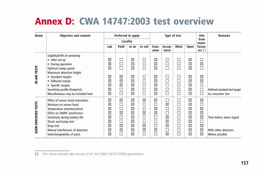
Name Objective and content Preferred to apply Type of test Info Remarks
Localityfrom
manu-Lab Field In air In soil Cons- Accep- Blind Open factur-
umer tance ers (*)
Stability/Drift of sensitivity• After set-up• During operationOptimal sweep speedMaximum detection height• Standard targets• Different metals• Specific targetsSensitivity profile (footprint) Defined standard test targetMiscellaneous may be included here As consumer test
Effect of sensor head orientationMoisture on sensor headTemperature extremes/shockEffect on EM/RF interferenceSensitivity during battery life Time before alarm signalShock and bump testDrop testMutual interference of detectors With other detectorsInterchangeability of parts Where possible
Annex D: CWA 14747:2003 test overview
157
IN A
IR T
ESTS
USE
R-SP
ECIF
IED
TES
TS
(*) For more details, see Annex C of the CWA 14747:2003 agreement.

158
Name Objective and content Preferred to apply Type of test Info Remarks
Localityfrom
manu-Lab Field In air In soil Cons- Accep- Blind Open factur-
umer tance ers (*)
Detection depth in different soils Measurements of soil• Standard targets As in air• Different metals As in air• Specific targets Chosen by end-userReliability tests
Locating accuracy (pinpointing) Not above minesShape determination of targets Point, linear, polygonResolution of adjacent targets AP and AT minesInfluence of specific mediaDetection near large linear metal Railway, fenceEffect of EM/RF interference Power lines, radioMutual interference of detectors Recovery test
IN S
OIL
AN
D F
IELD
TES
TS
In s
oil
Mis
cella
neou
s
(*) For more details, see Annex C of the CWA 14747:2003 agreement.

This annex describes how to calibrate the Schiebel metaldetector AN19/2 M7 before measuring the GRH. Thisprocess should be done before measuring the GRH ateach site.
The calibration is used to set the detectors to a repeatablesensitivity for measuring the GRH. This is necessary fortwo reasons. First, the detector must always be set up inthe same way if the GRH readings are to be meaningful.Secondly, the electronic units of these detectors are ‘indi-vidual’ and must be set to a common benchmark for theirresults to be interchangeable when different detectorsare used.
The targets to be used for this process are the Schiebeltest-piece (delivered with each detector) or a 10 mmdiameter chrome steel ball (53).
There are two ways to achieve the same sensitivity settings.
(a) The Schiebel test-piece is held 100 mm away from thecentre of the search-head in air. The sensitivity knob isthen moved clockwise to a point where a readingstarts. This should be repeated several times for con-firmation. The distance to the Schiebel test-piece
should not be measured from the real position of themetal piece but from the bottom of the arrow on theplastic cover (base of the arrow).
(b) A 10 mm diameter chrome steel ball is placed 140 mmaway from the centre of the search-head in air. Thesensitivity knob is then moved clockwise to a pointwhere a reading starts. This should be repeated several times for confirmation.
Use the marking and add another 50 mm for the Schiebeltest-piece, or use a 10 mm Ø chrome steel ball at 140 mmdistance to the centre of the search-head.
NB: Using the instructions above, whether the Schiebeltest-piece or the steel ball is used, the results in terms ofsetting a benchmark sensitivity will be similar enough togive interchangeable results.
After calibration, the measurement of the GRH (the heightat which the detector signals to the ground) is to be madewhen the detector makes the same sound as it did duringthe calibration procedure. At least five GRH measurementsshould be made at each place where a reading is taken andthe results should normally be within ± 5 mm of each other.This level of accuracy is both achievable in field conditions
(53) Chrome steel designations; UNS G52986, AISI 52100, UNI 100 Cr 6, DIN 1.3505.
Annex E: Calibration of the Schiebel AN19/2 M7
159


General
Brown, G. I., The Big Bang — a history of explosives, Sut-ton publishing, United Kingdom, 1998, ISBN 0 75091878 0 (hb)
GICHD, Mine action equipment: Study of global opera-tional needs, Geneva, 2002, ISBN 2-88487-004-0
Grant, Tim, The History of Landmines,http://members.iinet.net.au/~pictim/mines/history/history.html
Human Rights Watch, Landmine monitor report (annualpublication), International Campaign to Ban Landmines,www.hrw.org www.icbl.org
James Madison University, Journal of Mine Action (period-ical), Virginia, United States, http://maic.jmu.edu
McCracken, D., ‘Historical Development and Use of Land-mines’ paper in The Landmine Action Smart Book, Eds.Barlow, D.; Buse, M.; and Stephan, C., Mine ActionInformation Center — James Madison University,http://www.hdic.jmu.edu/Products/items/Smartbook/1Introduction.pdf
McGrath, Rae, Landmines and unexploded ordnance: Aresource book, Pluto Press, United Kingdom, 2000.
Monim and Gallimore, The Devil’s Gardens: A History ofLandmines, Random House, London, United Kingdom,2002, ISBN 0-7126-6859-4.
Schneck, William C., ‘The Origins of Military Mines’, Engi-neer Bulletin, July 1998, http://www.fas.org/man/dod-101/sys/land/mines.htm orhttp://tewton.narod.ru/history/istor-min-sneck.html
Smith, Andy (originator/editor), Database of DeminingAccidents (DDAS): software and data, GICHD, 2001: onrequest from [email protected]
US State Department, ’Milestones in Humanitarian Demi-ning’, Fact sheet, 22 February 2002,http://usinfo.state.gov/topical/pol/arms/minechron.htm
Technical
APOPO giant pouched rat research,http://www.apopo.org/
CEN workshop agreement, CWA 14747:2003 Humanitari-an Mine Action — Test and evaluation — Metal detec-tors, published 18 June 2003, http://humanitarian-security.jrc.it/demining/cw07/index.htm
Annex F: Suggested further reading
161

162
Das, Y.; Dean, J. T.; Lewis, D.; Roosenboom, J. H. J.; Za-haczewsky, G. (editors), International Pilot Project forTechnology Cooperation, Final Report, EUR 19719, EN— 2001, European Commission, JRC, 2001,http://demining.jrc.it/ipptc/
Fernandes, M., Lewis, A., and Littmann, F., ‘PROM 1 anti-personnel landmines (Possibility of activation by physi-cal contact with a metal detector)’, Technical noteNo S.P.I. 01.29.
Garrett, Charles, Modern metal detectors (Second edition),Ram Publishing Company, 1995, ISBN 0-915920-75-1.
Havard Bach, Biosensors Report:http://www.biosensor.se/dokument/biosensor_tech.pdf
King, Colin (Ed), Jane’s Mines and Mine Clearance (annualpublication), Jane’s Information Group, United King-dom, http://www.janes.com
RAND Science and Policy Institute, Alternatives for Land-mine Detection, 2003,http://www.rand.org/publications/MR/MR1608/index.html
Schubert, Hiltmar, and Kuznetsov, Andrey (editors), Detec-tion of explosives and landmines — methods and fieldexperience, NATO Science series, II Mathematics, Physicsand Chemistry — Vol. 66, Dordrecht, Boston, London,Kluwer Academic Publishers, 2002.
Sigrist, Christian, and Bruschini, Claudio, Metal Detectorsfor Humanitarian Demining: a Patent Search andAnalysis, revised December 2002,http://www.eudem.vub.ac.be/publications/files/MDPatentSearch/readme.htm
UNMAS, International Mine Action Standards, 2001, up-dated, 2003,http://www.mineactionstandards.org/imas.htm

Quick reference index for field users
Question Answer in section(s)
What is the minimum you should know about a detector before you enter 2.3; 5.3.2; 5.3.3; 5.4.2; 5.4.4; 5.4.5a mined area with it?
How does a metal detector work? 4.1
What is electromagnetic induction? 4.1; 4.3
What is the difference between ‘static’ and ‘dynamic’ detectors? 4.3.4
What is the difference between ‘pulse’ and ‘continuous wave’ detectors? 4.3
What kinds of search-head exist? 4.3.3; 4.3.5
What has to be checked before/after use? 2.3.1
What range of signals from a detector should you know? 2.3.1; 5.3.2; 4.4.5; 5.4.6; 5.4.7
What does ‘detector set-up’ mean? 6.1–3
What does the test-piece of the manufacture tell you? 2.3.2
What is a confidence test-piece? 2.3.2
What does ground compensation mean and how does it work? 4.5
How do you establish the safe advance for the detector sweep? 5.4.2; 5.4.3
Index
163

164
Question Answer in section(s)
What influences detector performance? 5.4.2; 6.1
How do you pinpoint a target? 5.4.8
How do you safely investigate a detector signal in a mined area? 2.3.4; 6.5
How do you set up a detector to a specific target? 2.3.1(d); 6.5
How do you establish the depth you can reliably clear to? 6.2–4

BBackscatter, neutron · 145, 146
Backscatter, x-ray · 142
Bacteria · 139, 140
Bartington · 72
Batteries · 31, 32, 34, 35, 63, 85, 102
Battery-life · 63
Bees · 138
Biosensors · 122, 162
Blast mine · 18, 19, 20, 21, 41, 44, 109, 110
BLU · 25, 153, 154
Booby traps · 16, 24, 46, 85, 112
Bounding mines · 85
Main index
165
AAccident · 21, 97, 99, 104, 113, 116, 145
Acoustic · 143
Action on getting a detector signal · 122
Adjacent targets · 109, 158
Adjustment, detector · 99, 118, 119, 121
ADP, UNADP · 8, 36, 97
Alluvial soil · 21
Anti-group mine (AG) · 7, 19
Antibody · 140, 147
Anti-personnel mine (AP) · 7, 18, 19, 20, 21, 24, 25, 38, 39,40, 41, 84, 109, 123, 151, 152, 153, 154, 155, 158
Anti-vehicle or anti-tank mine (AT) · 7, 19, 20, 21, 22, 40,41, 84, 85, 109, 145, 151, 152, 153, 154, 155, 158
Area-denial effect · 24
Area excavation · 20, 22

166
CCalibration test · 66
CEIA · 83, 84, 87
CEN workshop agreement · 60, 61
Chemical methods · 59, 132, 144, 146, 147, 148
Conductivity · 67, 71, 79, 91, 93, 141, 142
Confidence test-piece · 32, 34, 143
Continuous wave · 80, 83, 163
Convention on Conventional Weapons (CCW) · 7, 23
Copenhagen · 15
CWA 14747:2003 · 61, 62, 64, 65, 66, 76, 157, 161
DData fusion · 148
DDAS · 7, 97, 112, 161
Deeply buried ERW · 42
Detection capability · 65, 66, 67, 86, 93, 95, 96
Detection, factors affecting · 29, 84, 87, 92, 93, 106, 117
Detector performance · 59, 72, 75, 117, 164
Detector signal · 9, 17, 22, 31, 35, 36, 39, 45, 55, 59, 80, 84,87, 91, 96, 101, 108, 109, 110, 111, 117, 119, 122, 124,149, 159, 164
Detector signal, action on getting · 109, 116, 122, 129
Detector test-piece · 32
Dog handler · 136
Dogs · 17, 20, 21, 22, 23, 36, 38, 40, 120, 122, 128, 131,132, 136, 137, 138
Drift test · 67
EEbinger · 80, 83, 84
Eddy currents · 78, 79, 80, 93
EIT · 7, 141
Electro-chemical · 135, 148

167
Electromagnetic induction · 77, 78, 80, 96, 163
Electromagnetic interference (EMI) · 87
ERW · 7, 15, 16, 20, 23, 30, 36, 41, 42, 43, 97, 99, 121, 122,127, 128, 130, 131, 132, 135, 136, 141, 144
European Commission · 3, 60, 162
Evacuation · 88, 112
Excavate · 22, 36, 37, 105, 109, 123
Excavation procedures · 36
Explosive content of mines · 23, 131, 151
Explosive detecting dogs (EDDs) · 17, 23, 122, 131, 136, 137
Explosive detecting rats (EDRs) · 137, 138
FFalse alarms · 17, 128, 140, 145, 146, 148
Fast neutron · 7, 145
Field trials · 35, 62, 63, 64, 72, 139, 149
Flails · 23
Fluorescent polymer · 147
Fluxgate magnetometer · 43
Foerster · 82, 83, 84
Footprint · 32, 67, 93, 94, 95, 103, 105, 106, 107, 108, 157
Fragmentation mine · 19, 20, 39, 40, 85
Frequency-domain · 83, 86, 89
Fusion, data · 148
GGround compensation · 65, 86, 88, 89, 90, 95, 96, 106, 118,
163
Ground-penetrating radar (GPR) · 130, 141
Guartel. · 80, 84, 86
Gyata · 19, 45, 65, 70, 106, 152

168
HHandler,dog · 136
Hexogen (RDX) · 94
High explosive · 7, 19, 23, 24, 34, 131, 135, 136, 137, 144, 151
High voltage power lines · 54
HSTAMIDS · 149, 150
IIMAS · 7, 15, 27, 28, 60
Impedance · 7, 141
IMSMA · 71, 72,
Induction · 77, 78, 80, 85, 88, 96, 163
Influence on the performance · 68
Infrared · 8, 17, 142, 143
Injured person · 112
Insects · 137, 138
Interference, electromagnetic · 86, 87
Interference, magnetic ground · 22, 69, 70
Ion drift spectrometer · 146
IPPTC · 7, 63, 66, 67, 71, 103, 106
ITEP · 8, 60, 62, 106
ITOP · 8, 33, 34, 59, 60
JJoint Research Centre (JRC) of European Commission · 3,
94, 106, 161, 162
LLaterite · 91
Latest generation · 17
Linear targets · 66
Lines of flux · 77, 78

169
MM1 APD · 21
M14 · 19, 40, 136, 154
Machines · 20, 23, 39, 122, 128
Magnetic ground · 5, 9, 20, 30, 41, 42, 43, 65, 67, 68, 69,70, 71, 73, 74, 75, 91, 96, 117, 118, 135
Magnetometer · 42, 43
Metal detector · 9, 16, 19, 22, 28, 29, 30, 31, 32, 34, 39, 40,41, 42, 44, 45, 55, 59, 60, 61, 62, 63, 64, 65, 69, 72, 77,78, 79, 80, 88, 91, 93, 96, 97, 98, 99, 104, 106, 113, 115,117, 120, 122, 124, 127, 129, 131, 135, 148, 149, 150,159, 160, 162, 163
Metal detector standard · 59
Meteorological conditions · 75
Methods of detection · 20, 141
MIL standard · 59
Military use · 16, 17, 35, 63, 148
Mine Ban Treaty · 21, 24
Mine simulants · 17, 24, 46, 64
Mined area · 46, 47, 48, 51, 52, 53, 54, 55, 56, 57
Minelab · 80, 84, 87
Minimum metal mines · 40, 41, 65
Moisture test · 67
Mostar · 64
Multi-sensor · 148
NNational Institute of Justice (NIJ) · 59
Neutron · 145, 146
Nitroethane · 155
Nitromethane · 155
Nuclear quadrupole resonance (NQR) · 144
OOttawa Convention · 24

170
PPerformance characteristics · 61, 63
Permeability, magnetic · 92
PETN · 136, 152, 153, 154, 155
Picric acid · 154
Pinpointing · 36, 66, 84, 87, 110, 111, 158
Planning detector tests/trials · 73
Plants, detection by · 130, 132, 137, 139
PMA-1 · 152
PMA-2 · 40, 45, 152
PMA-3 · 19, 136, 154
PMN · 19, 45, 93, 111, 152, 153
Polymer, fluorescent · 147, 148
POMZ · 19, 40, 152
Primary magnetic field · 77, 78, 83, 84
Process of demining · 27
Prodder · 37, 97, 123
PROM · 19, 85, 162
Protocol II of the Convention on Conventional Weapons ·23, 24, 25
Pulsed induction · 80
QQA · 8, 17, 28, 120, 122, 131, 132, 139
RR2M2 · 40, 45, 153
Radio transmitters · 87
Rats · 135, 137, 138
RDX · 8, 136, 144, 151, 153, 154, 155
Remote sensing method for explosive detection · 131, 138
Rescue · 87, 112
Research and development · 88, 135, 144
Rollers · 23
171
SSafe distance · 21, 38, 105, 111, 113
Safety · 15, 21, 29, 32, 35, 44, 60, 64, 75, 77, 87, 97, 99,110, 117, 121, 127, 129, 130, 149, 150
Sarajevo · 64
Scan profile test · 67
Scatterable fragmentation mines · 20
Schiebel · 69, 80, 83, 84, 117, 120, 121, 159, 160
SD · 8, 24
SDA · 8, 24
Secondary magnetic field · 78, 79
Selection tests · 62
Semtex · 154
Sensitivity cone · 103
Sensitivity profile, field measurement · 32, 67, 93, 94, 95,103, 105, 106, 107, 108
Set-up, detector · 31, 32, 66, 100, 116, 117, 157, 163
Simulant mines · 33, 34, 44, 74, 105
Specific targets, adjusting to · 120
Spectrometer · 146
Submunition · 25
Surrogate mines · 32, 33, 34, 74, 109, 112
Survey · 27, 28, 64, 71, 98, 120, 121
Susceptibility · 67, 71, 92
Sweep speed test · 67
TTetryl · 136, 144, 154
Time domain · 12, 83, 86, 88, 89
TNT · 8, 136, 138, 144, 145, 148, 151, 152, 153, 154
Tomography · 7, 129, 141
Trainee competency · 105
Training · 3, 16, 40, 70, 71, 73, 74, 75, 87, 97, 98, 99, 100,101, 102, 103, 104, 105, 109, 111, 112, 113, 115, 121,128, 129, 132, 136, 137, 138, 139, 148

172
Content · 9, 16, 18, 21, 23, 24, 32, 40, 43, 44, 59, 60, 65, 68,70, 71, 75, 103, 104, 106, 110, 111, 112, 117, 119, 124,129, 131, 135, 136, 137, 143, 151, 157, 158
Preparation · 60, 74, 75, 100, 103, 111
Recommendations for trainers · 100
Requirements · 59, 60, 62, 75, 103, 104, 109, 143, 146, 147
Treaties · 23, 24
Trinitrotoluene · 8, 136, 151
Tripwire detection · 39, 122
Tripwires · 38, 39, 41, 66, 109, 112, 122, 132
Type 72 · 19, 40, 152, 154
UUNMAS · 8, 15, 60, 68, 162
UXO · 8, 16, 21, 27, 29, 37, 38, 43, 86, 109, 112, 120, 122
VVallon · 80, 84, 87
Valmara · 19, 41, 154
XX-ray · 142, 146


European Commission
EUR 20837 METAL DETECTOR HANDBOOK FOR HUMANITARIAN DEMINING
Luxembourg: Office for Official Publications of the European Communities
2003 — 172 pp. — 15 x 23 cm
ISBN 92-894-6236-1


BE
LGIQ
UE
/BE
LGIË
Jean
De
Lann
oyA
venu
e du
Roi
202
/Kon
ings
laan
202
B-1
190
Bru
xelle
s/B
russ
elT
él. (
32-2
) 53
8 43
08
Fax
(32
-2)
538
08 4
1E
-mai
l: je
an.d
e.la
nnoy
@in
fobo
ard.
beU
RL:
http
://w
ww
.jean
-de-
lann
oy.b
e
La li
brai
rie e
urop
éenn
e/D
e E
urop
ese
Boe
khan
del
Rue
de
la L
oi 2
44/W
etst
raat
244
B-1
040
Bru
xelle
s/B
russ
elT
él. (
32-2
) 29
5 26
39
Fax
(32
-2)
735
08 6
0E
-mai
l: m
ail@
libeu
rop.
beU
RL:
http
://w
ww
.libe
urop
.be
Mon
iteur
bel
ge/B
elgi
sch
Sta
atsb
lad
Rue
de
Louv
ain
40-4
2/Le
uven
sew
eg 4
0-42
B-1
000
Bru
xelle
s/B
russ
elT
él. (
32-2
) 55
2 22
11
Fax
(32
-2)
511
01 8
4E
-mai
l: eu
sale
s@ju
st.fg
ov.b
e
DA
NM
AR
K
J. H
. Sch
ultz
Info
rmat
ion
A/S
Her
sted
vang
4D
K-2
620
Alb
erts
lund
Tlf.
(45
) 43
63
23 0
0F
ax (
45)
43 6
3 19
69
E-m
ail:
schu
ltz@
schu
ltz.d
kU
RL:
http
://w
ww
.sch
ultz
.dk
DE
UT
SC
HLA
ND
Bun
desa
nzei
ger
Ver
lag
Gm
bHV
ertr
iebs
abte
ilung
Am
ster
dam
er S
traß
e 19
2D
-507
35 K
öln
Tel
. (49
-221
) 97
66
80F
ax (
49-2
21)
97 6
6 82
78
E-M
ail:
vert
rieb@
bund
esan
zeig
er.d
eU
RL:
http
://w
ww
.bun
desa
nzei
ger.
de
EL
LA
DA
/GR
EE
CE
G. C
. Ele
fther
ouda
kis
SA
Inte
rnat
iona
l Boo
ksto
reP
anep
istim
iou
17G
R-1
0564
Ath
ina
Tel
. (30
) 21
03
25 8
4 40
Fax
(30
) 21
03
25 8
4 99
E-m
ail:
eleb
ooks
@bo
oks.
grU
RL:
ww
w.b
ooks
.gr
ES
PA
ÑA
Bol
etín
Ofic
ial d
el E
stad
oT
rafa
lgar
, 27
E-2
8071
Mad
ridT
el.
(34)
915
3821
11(li
bros
),91
384
1715
(sus
crip
ción
)F
ax(3
4)91
538
2121
(libr
os),
913
8417
14(s
uscr
ipci
ón)
E-m
ail:
clie
ntes
@co
m.b
oe.e
sU
RL:
http
://w
ww
.boe
.es
Mun
di P
rens
a Li
bros
, SA
Cas
telló
, 37
E-2
8001
Mad
ridT
el. (
34)
914
36 3
7 00
Fax
(34
) 91
5 75
39
98E
-mai
l: lib
reria
@m
undi
pren
sa.e
sU
RL:
http
://w
ww
.mun
dipr
ensa
.com
FR
AN
CE
Jour
nal o
ffici
elS
ervi
ce d
es p
ublic
atio
ns d
es C
E26
, rue
Des
aix
F-7
5727
Par
is C
edex
15
Tél
. (33
) 14
0 58
77
31F
ax (
33)
140
58 7
7 00
E-m
ail:
euro
publ
icat
ions
@jo
urna
l-offi
-ci
el.g
ouv.
frU
RL:
http
://w
ww
.jour
nal-o
ffici
el.g
ouv.
fr
IRE
LAN
D
Ala
n H
anna
’s B
ooks
hop
270
Low
er R
athm
ines
Roa
dD
ublin
6T
el. (
353-
1) 4
96 7
3 98
Fax
(35
3-1)
496
02
28E
-mai
l: ha
nnas
@io
l.ie
ITA
LIA
Lico
sa S
pAV
ia D
uca
di C
alab
ria, 1
/1C
asel
la p
osta
le 5
52I-
5012
5 F
irenz
eT
el. (
39)
05 5
6 48
31
Fax
(39
) 05
5 64
12
57E
-mai
l: lic
osa@
licos
a.co
mU
RL:
http
://w
ww
.lico
sa.c
om
LUX
EM
BO
UR
G
Mes
sage
ries
du li
vre
SA
RL
5, r
ue R
aiffe
isen
L-24
11 L
uxem
bour
gT
él. (
352)
40
10 2
0F
ax (
352)
49
06 6
1E
-mai
l: m
ail@
mdl
.luU
RL:
http
://w
ww
.mdl
.lu
NE
DE
RLA
ND
SD
U S
ervi
cece
ntru
m U
itgev
ers
Chr
isto
ffel P
lant
ijnst
raat
2P
ostb
us 2
0014
2500
EA
Den
Haa
gT
el. (
31-7
0) 3
78 9
8 80
Fax
(31
-70)
378
97
83E
-mai
l: sd
u@sd
u.nl
UR
L: h
ttp://
ww
w.s
du.n
l
PO
RT
UG
AL
Dis
trib
uido
ra d
e Li
vros
Ber
tran
d Ld
.a
Gru
po B
ertr
and,
SA
Rua
das
Ter
ras
dos
Val
es, 4
-AA
part
ado
6003
7P
-270
0 A
mad
ora
Tel
. (35
1) 2
14 9
5 87
87
Fax
(35
1) 2
14 9
6 02
55
E-m
ail:
dlb@
ip.p
t
Impr
ensa
Nac
iona
l-Cas
a da
Moe
da, S
AS
ecto
r de
Pub
licaç
ões
Ofic
iais
Rua
da
Esc
ola
Pol
itécn
ica,
135
P-1
250
-100
Lis
boa
Cod
exT
el. (
351)
213
94
57 0
0F
ax (
351)
213
94
57 5
0E
-mai
l: sp
oce@
incm
.pt
UR
L: h
ttp://
ww
w.in
cm.p
t
SU
OM
I/FIN
LAN
D
Aka
teem
inen
Kirj
akau
ppa/
Aka
dem
iska
Bok
hand
eln
Kes
kusk
atu
1/C
entr
alga
tan
1P
L/P
B 1
28F
IN-0
0101
Hel
sink
i/Hel
sing
fors
P./t
fn (
358-
9) 1
21 4
4 18
F./f
ax (
358-
9) 1
21 4
4 35
Säh
köpo
sti:
akat
ilaus
@ak
atee
min
en.c
omU
RL:
http
://w
ww
.aka
teem
inen
.com
SV
ER
IGE
BT
J A
BT
rakt
orvä
gen
11-1
3S
-221
82
Lund
Tfn
(46
-46)
18
00 0
0F
ax (
46-4
6) 3
0 79
47
E-p
ost:
btje
u-pu
b@bt
j.se
UR
L: h
ttp://
ww
w.b
tj.se
UN
ITE
D K
ING
DO
M
The
Sta
tione
ry O
ffice
Ltd
Cus
tom
er S
ervi
ces
PO
Box
29
Nor
wic
h N
R3
1GN
Tel
. (44
-870
) 60
05-
522
Fax
(44
-870
) 60
05-
533
E-m
ail:
book
.ord
ers@
thes
o.co
.uk
UR
L: h
ttp://
ww
w.ts
o.co
.uk
ÍSLA
ND
Bok
abud
Lar
usar
Blö
ndal
Eng
jate
igi 1
7-19
IS-1
05 R
eykj
avik
Tel
. (35
4) 5
52 5
5 40
Fax
(35
4) 5
52 5
5 60
E-m
ail:
boka
bud@
sim
net.i
s
NO
RG
E
Sw
ets
Bla
ckw
ell
AS
Han
s N
iels
en H
auge
s gt
. 39
Bok
s 49
01 N
ydal
enN
-042
3 O
slo
Tel
. (47
) 23
40
00 0
0F
ax (
47)
23 4
0 00
01
E-m
ail:
info
@no
.sw
etsb
lack
wel
l.com
SC
HW
EIZ
/SU
ISS
E/S
VIZ
ZE
RA
Eur
o In
fo C
ente
r S
chw
eiz
c/o
OS
EC
Bus
ines
s N
etw
ork
Sw
itzer
land
Sta
mpf
enba
chst
raß
e 85
PF
492
CH
-803
5 Z
üric
hT
el. (
41-1
) 36
5 53
15
Fax
(41
-1)
365
54 1
1E
-mai
l: ei
cs@
osec
.ch
UR
L: h
ttp://
ww
w.o
sec.
ch/e
ics
B@
LGA
RIJ
A
Eur
opre
ss E
urom
edia
Ltd
59, b
lvd
Vito
sha
BG
-100
0 S
ofia
Tel
. (35
9-2)
980
37
66F
ax (
359-
2) 9
80 4
2 30
E-m
ail:
Mile
na@
mbo
x.ci
t.bg
UR
L: h
ttp://
ww
w.e
urop
ress
.bg
CY
PR
US
Cyp
rus
Cha
mbe
r of
Com
mer
cean
d In
dust
ryP
O B
ox 2
1455
CY
-150
9 N
icos
iaT
el. (
357-
22)
88 9
7 52
Fax
(35
7-22
) 66
10
44E
-mai
l: st
alo@
ccci
.org
.cy
EE
ST
I
Ees
ti K
auba
ndus
-Töö
stus
koda
(Est
onia
nC
ham
bero
fCom
mer
cean
dIn
dust
ry)
Too
m-K
ooli
17E
E-1
0130
Tal
linn
Tel
. (37
2) 6
46 0
2 44
Fax
(37
2) 6
46 0
2 45
E-m
ail:
einf
o@ko
da.e
eU
RL:
http
://w
ww
.kod
a.ee
HR
VA
TS
KA
Med
iatr
ade
Ltd
Str
ohal
ov P
rilaz
27
HR
-100
00 Z
agre
bT
el. (
385-
1) 6
60 0
8 40
Fax
(38
5-1)
660
21
65E
-mai
l: m
edia
trad
e@hi
.hin
et.h
r
MA
GY
AR
OR
SZ
ÁG
Eur
o In
fo S
ervi
ceS
zt. I
stvá
n kr
t.12
IIl e
mel
et 1
/AP
O B
ox 1
039
H-1
137
Bud
apes
tT
el. (
36-1
) 32
9 21
70
Fax
(36
-1)
349
20 5
3E
-mai
l: eu
roin
fo@
euro
info
.hu
UR
L: h
ttp://
ww
w.e
uroi
nfo.
hu
MA
LTA
Mill
er D
istr
ibut
ors
Ltd
Mal
ta In
tern
atio
nal A
irpor
tP
O B
ox 2
5Lu
qa L
QA
05
Tel
. (35
6) 2
1 66
44
88F
ax (
356)
21
67 6
7 99
E-m
ail:
info
@m
iller
mal
ta.c
om
PO
LSK
A
Ars
Pol
ona
Kra
kow
skie
Prz
edm
iesc
ie 7
Skr
. poc
ztow
a 10
01P
L-00
-950
War
szaw
aT
el. (
48-2
2) 8
26 1
2 01
Fax
(48
-22)
826
62
40E
-mai
l: bo
oks1
19@
arsp
olon
a.co
m.p
l
RO
MÂ
NIA
Eur
omed
iaS
tr.D
ioni
sie
Lupu
nr.
65,
sec
tor
1R
O-7
0184
Buc
ures
tiT
el. (
40-2
1) 2
60 2
8 82
Fax
(40
-21)
260
27
88E
-mai
l: eu
rom
edia
@m
ailc
ity.c
om
SLO
VA
KIA
Cen
trum
VT
I SR
Nám
estie
Slo
body
19
SK
-812
23 B
ratis
lava
1T
el. (
421-
2) 5
4 41
83
64F
ax (
421-
2) 5
4 41
83
64E
-mai
l: eu
rop@
tbb1
.cvt
isr.
skU
RL:
http
://w
ww
.cvt
isr.
sk
SLO
VE
NIJ
A
GV
Zal
ozba
d.o
.o.
Dun
ajsk
a ce
sta
5S
I-10
00 L
jubl
jana
Tel
. (38
6) 1
3 09
180
0F
ax (
386)
13
09 1
805
E-m
ail:
euro
p@gv
zalo
zba.
siU
RL:
http
://w
ww
.gvz
aloz
ba.s
i
TÜ
RK
IYE
Dün
ya A
ktüe
l A.S
Glo
bus
Dün
ya B
asin
evi
100,
Yil
Mah
alle
ssi 3
4440
TR
-800
50 B
agci
lar-
Ista
nbul
Tel
. (90
-212
) 44
0 22
27
Fax
(90
-212
) 44
0 23
67
E-m
ail:
aktu
el.in
fo@
duny
a.co
m
AR
GE
NT
INA
Wor
ld P
ublic
atio
ns S
AA
v. C
órdo
ba 1
877
C11
20 A
AA
Bue
nos
Aire
sT
el. (
54-1
1) 4
8 15
81
56F
ax (
54-1
1) 4
8 15
81
56E
-mai
l: w
pboo
ks@
info
via.
com
.ar
UR
L: h
ttp://
ww
w.w
pboo
ks.c
om.a
r
AU
ST
RA
LIA
Hun
ter
Pub
licat
ions
PO
Box
404
Abb
otsf
ord,
Vic
toria
306
7T
el. (
61-3
) 94
17
53 6
1F
ax (
61-3
) 94
19
71 5
4E
-mai
l: ad
min
@te
kim
agin
g.co
m.a
u
BR
AS
IL
Livr
aria
Cam
ões
Rua
Bitt
enco
urt d
a S
ilva,
12
CC
EP
2004
3-90
0 R
io d
e Ja
neiro
Tel
. (55
-21)
262
47
76F
ax (
55-2
1) 2
62 4
7 76
E-m
ail:
livra
ria.c
amoe
s@in
cm.c
om.b
rU
RL:
http
://w
ww
.incm
.com
.br
CA
NA
DA
Les
éditi
ons
La L
iber
té In
c.
3020
, che
min
Sai
nte-
Foy
Sai
nte-
Foy
, Qué
bec
G1X
3V
6T
él. (
1-41
8) 6
58 3
7 63
Fax
(1-
800)
567
54
49E
-mai
l: lib
erte
@m
edio
m.q
c.ca
Ren
ouf P
ublis
hing
Co.
Ltd
5369
Che
min
Can
otek
Roa
d U
nit 1
Otta
wa,
Ont
ario
K1J
9J3
Tel
. (1-
613)
745
26
65F
ax (
1-61
3) 7
45 7
6 60
E-m
ail:
orde
r.de
pt@
reno
ufbo
oks.
com
UR
L: h
ttp://
ww
w.r
enou
fboo
ks.c
om
EG
YP
T
The
Mid
dle
Eas
t Obs
erve
r
41 S
herif
Str
eet
1111
1 C
airo
Tel
. (20
-2)
392
69 1
9F
ax (
20-2
) 39
3 97
32
E-m
ail:
meo
@so
ficom
.com
.eg
UR
L: h
ttp://
ww
w.m
eobs
erve
r.co
m.e
g
MA
LAY
SIA
EB
IC M
alay
sia
Sui
te 4
7.01
, Lev
el 4
7B
angu
nan
Am
Fin
ance
(le
tter
box
47)
8 Ja
lan
Yap
Kw
an S
eng
5045
0 K
uala
Lum
pur
Tel
. (60
-3)
21 6
2 62
98
Fax
(60
-3)
21 6
2 61
98
E-m
ail:
ebic
@tm
.net
.my
MÉ
XIC
O
Mun
di P
rens
a M
éxic
o, S
A d
e C
V
Río
Pán
uco,
141
Col
onia
Cua
uhté
moc
MX
-065
00 M
éxic
o, D
FT
el. (
52-5
) 53
3 56
58
Fax
(52
-5)
514
67 9
9E
-mai
l: 10
1545
.236
1@co
mpu
serv
e.co
m
SO
UT
H K
OR
EA
The
Eur
opea
n U
nion
Cha
mbe
r of
Com
mer
ce in
Kor
ea
Sui
te 2
004,
Kyo
bo B
ldg.
1 C
hong
ro 1
-Ga,
Cho
ngro
-Gu
Seo
ul 1
10-7
14T
el. (
82-2
) 72
5-98
80/5
Fax
(82
-2)
725-
9886
E-m
ail:
eucc
k@eu
cck.
org
UR
L: h
ttp://
ww
w.e
ucck
.org
SR
I LA
NK
A
EB
IC S
ri La
nka
Tra
ns A
sia
Hot
el11
5 S
ir C
hitta
mpa
lam
A. G
ardi
ner
Maw
atha
Col
ombo
2T
el. (
94-1
) 07
4 71
50
78F
ax (
94-1
) 44
87
79E
-mai
l: eb
icsl
@sl
tnet
.lk
T’A
I-W
AN
Tyc
oon
Info
rmat
ion
Inc
PO
Box
81-
466
105
Tai
pei
Tel
. (88
6-2)
87
12 8
8 86
Fax
(88
6-2)
87
12 4
7 47
E-m
ail:
eiut
pe@
ms2
1.hi
net.n
et
UN
ITE
D S
TA
TE
S O
F A
ME
RIC
A
Ber
nan
Ass
ocia
tes
4611
-F A
ssem
bly
Driv
eLa
nham
MD
207
06-4
391
Tel
. (1-
800)
274
44
47 (
toll
free
tele
phon
e)F
ax (
1-80
0) 8
65 3
4 50
(to
ll fr
ee fa
x)E
-mai
l: qu
ery@
bern
an.c
omU
RL:
http
://w
ww
.ber
nan.
com
AN
DE
RE
LÄ
ND
ER
/OT
HE
R C
OU
NT
RIE
S/
AU
TR
ES
PA
YS
Bitt
e w
ende
n S
ie s
ich
an e
in B
üro
Ihre
rW
ahl/P
leas
e co
ntac
t the
sal
es o
ffice
of
your
cho
ice/
Veu
illez
vou
s ad
ress
er a
ubu
reau
de
vent
e de
vot
re c
hoix
Offi
ce fo
r O
ffici
al P
ublic
atio
nsof
the
Eur
opea
n C
omm
uniti
es2,
rue
Mer
cier
L-29
85 L
uxem
bour
gT
el. (
352)
29
29-4
2001
Fax
(35
2) 2
9 29
-427
00E
-mai
l: in
fo-in
fo-o
poce
@ce
c.eu
.int
UR
L: h
ttp://
publ
icat
ions
.eu.
int
7/20
03
Ven
ta•
Sal
g•
Ver
kauf
•P
vlè
sei
w•
Sal
es•
Ven
te•
Ven
dita
•V
erko
op•
Ven
da•
Myy
nti
•F
örsä
ljnin
ght
tp://
eur-
op.e
u.in
t/gen
eral
/en/
s-ad
.htm

ISBN 92-894-6236-1
9 789289 462365
15LB
-NA
-20-837-EN
-C