mescoot b handbook - mike eitel start frame b handbook.pdfmescoot bernard handbook me, lh, 02.05.12...
TRANSCRIPT

Me, LH, 02.05.12
1 - 14
MeScoot B Handbook.docx
MeScoot Bernard Handbook
Length 120 cm
Weight 34 Kg
Motor Power Adjustable, set to max 1 KW
Light brightness Adjustable, set to ca 5000 Lumen gross, 22°
Battery LiFePo4, 48v nominal, 15 Ah
Thrust > 25Kg
Main Features:
• Completely microprocessor controlled.
• Device on/off while closed housing with zero consumption when off.
• Manual fast switch off plus auto switch off, selectable 5/10/15/60 min.
• Regulated throttle controlled by potentiometer on top.
• Constant speed independent from battery voltage.
• Motor power ca. 100W to 1 KW. Current restricted to max. 20A.
• Different selectable ramp up / down time for motor.
• 5 different brightness steps, up to ca. 5000 lumen.
• Water intrusion detection with buzzer and LED warning.
• Buzzer can be switched off permanently.
• Multi color LED to show status.
• Voltage value shown by LED.
• Motor temperature shown by LED.
All rights reserved by:
Mike Eitel
Hügelweg 7
Ch-8224 Löhningen
+41 79 416 50 22

MeScoot Bernard Handbook Me, LH, 02.05.12
2 - 14
MeScoot B Handbook.docx
Index
Main Features: ............................................................................. 1
Command sequences .................................................................... 3
Start up 3
Normal operation signalization ............................................................... 3
Normal operation motor ......................................................................... 3
Normal operation light ........................................................................... 3
Shut down .............................................................................................. 3
Water intrusion ...................................................................................... 3
The mechanics .............................................................................. 4
Retrofitting ............................................................................................. 4
The electronic ............................................................................... 5
The light controller ................................................................................. 7
Brightness ................................................................................................ 7
Temperature ........................................................................................... 7
The power board .................................................................................... 7
Current .................................................................................................... 7
Speed ....................................................................................................... 8
The processor board ............................................................................... 8
Connector LED ......................................................................................... 8
Temperature sensor ................................................................................ 9
Potentiometer Voltage ............................................................................ 9
Potentiometer Motor current ................................................................. 9
Switch Auto Off time ............................................................................. 10
Switch Motor ramp timing .................................................................... 10
Switch Buzzer on ................................................................................... 10
Switch Water simulation ....................................................................... 10
The connections of battery and water detection ................................... 11
The battery ............................................................................................ 11
The water detection .............................................................................. 11
The test ...................................................................................... 12
Program code ............................................................................. 13
Circuit Drawings ......................................................................... 14

MeScoot Bernard Handbook Me, LH, 02.05.12
3 - 14
MeScoot B Handbook.docx
Command sequences
Simple instruction: Device is handled in the following way.
Start up
1. Load the battery and mount completely.
2. Press both switches for 5 seconds
3. Release throttle first
Normal operation signalization
• LED shows green with growing red phase for voltage ( 45 to 52 Volts)
• Next LED blue growing to violet for 40 to 65 degrees Celsius
Normal operation motor
• Now pressing throttle starts motor with ramp up.
• Releasing stops with different faster ramp down.
Normal operation light
• Short click on light switch goes one step up. 5 / 15 / 30 / 50 / 100 %
• Longer click steps one down.
• Quite long click switches light off directly.
Shut down
1. Even longer click on light prepares fast device off, shown by blinking
red LED.
2. This command is accepted as soon as motor is clicked and released.
Water intrusion
• Water intrusion is always shown by blinking blue LED and when
allowed by buzzer
LIGHT
Motor
LED
Speed

MeScoot Bernard Handbook Me, LH, 02.05.12
4 - 14
MeScoot B Handbook.docx
The mechanics
The body is based on an old military scooter, refurbished by Bernard himself.
Retrofitting
Bernard did a complete cleaning and repainting and exchange of O rings etc.
MeScoot Bernard Handbook Me, LH, 02.05.12
5 - 14
MeScoot B Handbook.docx
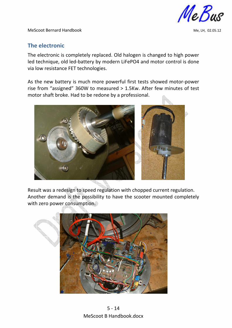
The electronic
The electronic is completely replaced. Old halogen is changed to high power
led technique, old led-battery by modern LiFePO4 and motor control is done
via low resistance FET technologies.
As the new battery is much more powerful first tests showed motor-power
rise from “assigned” 360W to measured > 1.5Kw. After few minutes of test
motor shaft broke. Had to be redone by a professional.
Result was a redesign to speed regulation with chopped current regulation.
Another demand is the possibility to have the scooter mounted completely
with zero power consumption.

MeScoot Bernard Handbook Me, LH, 02.05.12
6 - 14
MeScoot B Handbook.docx
Main light is now led based.
Everything is controlled by a microcontroller from Atmel ATMEGA32.
The complete electronic is distributed over three main PCB’s.
• The light controller
• The power board
• The processor board

MeScoot Bernard Handbook Me, LH, 02.05.12
7 - 14
MeScoot B Handbook.docx
The light controller
The light controller is mounted on the new led based light unit. The unit is
fabricated from massif aluminum and is placed between the body and the
glass, using the six old screw holes. It is has three LED-TECH 4 x Cree
XPGWHT-L1-1T-R5 led-PCB with changeable optics of 22° or 44°.
Brightness
The potentiometer allows adjusting the maximum brightness by regulating
the max current
Temperature
The potentiometer allows adjusting the maximum temperature by cutting
down the max current to 20% when threshold is reached. Momentary the
temperature is set to ca 50 degrees Celsius of the light-aluminum block.
The power board
The power board consists of the interfaces to power supply, motor, red-
contacts, speed potentiometer of the body.
Current
Brightness
Temperature
Current
Low Speed
High Speed

MeScoot Bernard Handbook Me, LH, 02.05.12
8 - 14
MeScoot B Handbook.docx
The potentiometer for the current control limits the maximum current thru
the motor. Via a comparator and flip-flop it’s stopping the main current
switch, a FET. The FF is reset with a fixed frequency of ca 25 kHz. That way
the battery is protected against to high current when motor is not turning.
Momentary it is set to ca 20A.
Speed
The speed is controlled by the main potentiometer on the housing. But there
are two additional potentiometers which change the max and the min speed.
The processor board
There are two potentiometers for voltage and motor current measure and
six switches to set device behavior
Connector LED
The Led is plugged via a 4-pin connector. That
way it is possible to remove the complete
electronics without the need of dismounting
the led from the waterproof PG, on top of the
scooter body.
Current
Temperature
LED
Switches
Voltage

MeScoot Bernard Handbook Me, LH, 02.05.12
9 - 14
MeScoot B Handbook.docx
Temperature sensor
The motor temperature is measured via a fix-cable NTC. The only way to
dismount is to unscrew the bracket on the motor and remove the copper
bracket with the sensor.
Potentiometer Voltage
The device voltage is measured and used for LED and LCD signalization. Via a
potentiometer the value coming from the power board is adapted to the
MCU input.
Potentiometer Motor current
The motor current is not identical with the battery current. Via a
potentiometer the value coming from the power board is adapted to the
MCU input. This value is shown on the LCD.

MeScoot Bernard Handbook Me, LH, 02.05.12
10 - 14
MeScoot B Handbook.docx
Switch Auto Off time
The time for auto switch of can be changed via the dip-switches 1 and 2.
Switch 1 Switch 2 Time until auto-off
OFF OFF 5 minutes
ON OFF 10 minutes
OFF ON 15 minutes
ON ON 60 minutes
Switch Motor ramp timing
The motor has two different ramps for up and down. The can be influenced
independently. The time is always the same between slow to fast speed.
That means the acceleration is always the same, when potentiometer is on
position half speed, time is reached in half of the ramp time.
Switch 3 Switch 4 Time until auto-off
OFF OFF Ramp UP slow
ON OFF Ramp UP fast
OFF ON Ramp DOWN slow
ON ON Ramp DOWN fast
Switch Buzzer on
The alarm signal for water and auto off is also driving a buzzer, with the
switch 5 this function can be canceled permanently.
Switch 5 Buzzer
OFF Buzzer off
ON Buzzer on
Switch Water simulation
The water detection can be tested with the switch 6.
Switch 6 Water
OFF Water detection in normal operation
ON Water detection simulated on.

MeScoot Bernard Handbook Me, LH, 02.05.12
11 - 14
MeScoot B Handbook.docx
The connections of battery and water detection
Both parts of the body can be separated completely.
The battery
The connector includes battery and LED
The water detection
The cable has to be connected with the
according pin in the body.
The connections of LCD and ISP programmer cable
Its possible to program inline with normal Atmel ISP programmer. And also
to connect a text LCD directly to MCU and see internal values for test.
Water detection
Battery
ISP prog. cable
LCD via cable

MeScoot Bernard Handbook Me, LH, 02.05.12
12 - 14
MeScoot B Handbook.docx
The test
The test was very successful.
Fast, non precise measurement showed more than 25 Kg impulse.

MeScoot Bernard Handbook Me, LH, 02.05.12
13 - 14
MeScoot B Handbook.docx
Program code ' -----[ Program Description ]------------------------------------------------------------- ' ' This program is used to control the scooter of Bernard Joly ' It's written for Bascom Version 2.0.7.4 from www.mcselec.com ' ' -----[ Disclaimer ]---------------------------------------------------------------------- ' ' This program is offered on an "AS IS" basis, no warranty expressed or implied. The ' programmer disclaims liability of any damages associated with the use of the hardware or ' software described herein. If you got the permission to use it you use it on your own ' risk. The author is not able to provide any free support. ' ' Copyright (c)1999 - 2012 Mike Eitel all rights reserved ' ' -----[ Revision History ]-------------------------------------------------------------- ' ' 131111 - Ver 0.80 Test HW Mike Eitel ' 200212 - Ver 0.90 First LED and LCD implementation Mike Eitel ' 200212 - Ver 0.91 Change to multitasking Mike Eitel ' 250312 - Ver 0.95 Final HW test implementation Mike Eitel ' 250312 - Ver 0.99 First implementation of all features Mike Eitel ' 160412 - Ver 1.00 First finished implementation Mike Eitel ' ' -----[ Basic HW definitions ]------------------------------------------------------------ ' 'ATMEGA32 Sig. PIN Device Sig. PIN Device 'PortA.0 AD0 40 Analog_MESS_V+ 'PinB.0 T0 01 IN_MOTOR_ON grey 'PortA.1 AD1 39 Analog_MESS_V+ 'PinB.1 T1 02 IN_LIGHT_ON white 'PortA.2 AD2 38 Analog_MESS_V+ 'PortB.2 INT2 03 OUT_RELAIS_ON violet 'PortA.3 AD3 37 Analog_MESS_V+ 'PortB.3 OCO 04 OUT_PWM_MOTOR yellow 'PortA.4 AD4 36 Analog_MESS_CUR 'PortB.4 /SS 05 Db4 LCD Pin 11 'PortA.5 AD5 35 Analog_MESS_CUR 'PxxxB.5 MOSI 06 ISP 'PortA.6 AD6 34 Analog_MESS_CUR 'PxxxB.6 MISO 07 ISP 'PortA.7 AD7 33 Analog_MESS_TMP 'PxxxB.7 SCK 08 ISP 'PortC.7 TOSC2 29 LED RED 'PinD.0 RXD 14 IN-Water & SWITCH-6 'PortC.6 TOSC1 28 LED GREEN 'PortD.1 TXD 15 Buzzer-OUT 'PortC.5 TDI 27 LED BLUE 'PortD.2 INT0 16 Rs LCD Pin 4 'PinC.4 TDO 26 IN_SW-1 'PortD.3 INT1 17 E LCD Pin 6 'PinC.3 TMS 25 IN_SW-2 'PortD.4 OC1B 18 Db5 LCD Pin 12 'PinC.2 TCK 24 IN_SW-3 'PortD.5 OC1A 19 Db6 LCD Pin 13 'PinC.1 SDA 23 IN_SW-4 'PortD.6 ICP1 20 Db7 LCD Pin 14 'PinC.0 SCL 22 IN_SW-5 'PortD.7 OC2 21 OUT_PWM_LED $regfile = "m32def.dat" 'regfile match the chip $crystal = 8000000 'crystal must match too $regfile = "m32def.dat" 'regfile match the chip $crystal = 8000000 'crystal must match too $prog &HFF , &H44 , &HD9 , &H00 ' generated. ' FB Fusebit settings ' FBH Fusebit High set. ' FBX Extended Fusebit ' -----[ Define ports ]-------------------------------------------------------------------- …………….

MeScoot Bernard Handbook Me, LH, 02.05.12
14 - 14
MeScoot B Handbook.docx
Electronics principal drawing