mesa boogie mark 1 re issue owner's manual manuals/mark1 reissue.pdf · carlton, robben ford,...
TRANSCRIPT
OOGIEBMESA
MARK 1 RE -ISSUE Owner's Manual

Hello from the Tone Farm
...You, smart player and all around intuitive human, have put your trust in us to be your amplifier company. This is something we do not take lightly. By purchasing and choosing this unit to be a part of your musical voice, you have become part of the Mesa family...WELCOME! Our goal is to never let you down. Your reward is that you are now the owner of a great amp, bred of fine all tube amp heritage...benefiting from the many pioneering and patented Mesa circuits that led to the refinement of your new instrument. Feel confident, as we do, this amp will inspire many hours of musical satisfaction and lasting enjoyment. It was built with you in mind, by players who know the value of a fine musical instrument and the commitment it takes to make great music. The same commitment to quality, value and support we make to you...our new friend.

FRONT PANEL:
REAR PANEL:
PrecautionsOverview 1
Inputs 1 & 2 / Volumes 1 & 2 2Treble 2 / 3Bass 3Middle 3Toggle Switches60 / 100 3Standby Switch 4Power / Tweed Switch 4 / 5
A.C. Receptacle 5Fuse 5Ground 5FX Loop & Level Control 6Slave 6Presence 7Reverb 7Speaker Jacks 7Tube Task Chart 8Personal Settings Page 9Tube Maintenance 10 /11Speaker Impedance Matching & Hook-Up Guide 12/13Wiring Schemes - Amplifier to Speaker Cabinets 14/17Bias Adjustment: a feature article by Randall Smith 18 /20On Triodes, Pentodes & Irishmen: a feature article by Randall Smith 21/23Parts Sheet 24
Table of Contents
MK-1
PRECAUTIONS & WARNINGSYour MESA/Boogie Amplifier is a professional instrument. Please treat it with respect and operate it properly.
USE COMMON SENSE AND ALWAYS OBSERVE THESE PRECAUTIONS:
YOUR AMPLIFIER IS LOUD! EXPOSURE TO HIGH SOUND VOLUMES MAY CAUSE PERMANENT HEARING DAMAGE !
No user serviceable parts inside. Refer service to qualified personnel. Always unplug AC power before removing chassis.
EXPORT MODELS: Always insure that unit is wired for proper voltage. Make certain grounding conforms with local standards.
READ AND FOLLOW INSTRUCTIONS OF PROPER USAGE.
WARNING: EU: permission from the Supply Authority is needed before connection.
WARNING: Vacuum tube amplifiers generate heat. To insure proper ventilation always make certain there is at least four inches (100mm) of space behind the rear of the amplifier cabinet. Keep away from curtains or any flammable objects.
WARNING: Do not block any ventilation openings on the rear or top of the amplifier. Do not impede ventilation by placing objects on top of the amplifier which extend past the rear edge of its cabinet.
WARNING: Do not expose the amplifier to rain, moisture, dripping or splashing water. Do not place objects filled with liquids on or nearby the amplifier.
WARNING: Always make certain proper load is connected before operating the amplifier. Failure to do so could pose a shock hazard and may result in damage to the amplifier.
Do not expose amplifier to direct sunlight or extremely high temperatures.
Always insure that amplifier is properly grounded. Always unplug AC power cord before changing fuse or any tubes. When replacing fuse, use only same type and rating.
Avoid direct contact with heated tubes. Keep amplifier away from children.
Be sure to connect to an AC power supply that meets the power supply specifications listed on the rear of the unit. Remove the power plug from the AC mains socket if the unit is to be stored for an extended period of time. If there is any danger of lightning occurring nearby, remove the power plug from the wall socket in advance.
To avoid damaging your speakers and other playback equipment, turn off the power of all related equipment before making the connections.
Do not use excessive force in handling control buttons, switches and controls. Do not use solvents such as benzene or paint thinner to clean the unit. Wipe off the exterior with soft cloth.
Be sure to have the warranty card filled out by the store at which it was purchased and return to Mesa/Boogie.

PAGE 1
VOLUME 2 MASTERVOLUME 1 BASS MIDDLE
2
5 678
1 0 109
34
2
5 678
1 0 109
34
2
5 678
1 0 109
34
2
5 678
1 0 109
34
2
5 678
1 0 109
34
POWER
60 RMS STANDBY TWEED
MARK I
ON100 RMS
1
2
TREBLE
FRONT VIEW: Mk 1
2
5 678
1 0 109
34
FUSE
8 4 4
3A GRND SLAVE LOOP PRES REV SPKRS
IN
2
5 678
1 0 109
34
2
5 678
1 0 109
34
2
5 678
1 0 109
34
FX LEVEL
OUT IN
REAR VIEW: Mk 1
OVERVIEW:
CONGRATULATIONS ! You’ve just become the proud owner of one of the most influential guitar amplifiers ever made - the BoogieMARK 1 ! This is the legendary amp that introduced all of the features most in demand by players today ! The Boogie MARK 1gave birth to the Multi-Stage High Gain Preamp, the 100/60 or Half Power switch, Direct or Line-Out the Preamp In/Out Jacks (EffectsLoop) and Pull Shift functions, too name just a very few. Aside from its tremendous impact on amplifier desigh, the Boogie MARK 1played a digantic role in shaping the sound of today’s guitarists. With its radically boosted preamp, monstrous power output and topquality rube circuitry, the Boogie MARK 1 produced tone that was unheard of in its day ! The MARK 1’S fat, warm, creamy soundushered in the era of High Gain-Singing Sustain lead tone and quickly became the instrument of choice for many of the 70’s greatestinnovators.
Carlos Santana first unveiled this tone on his early Abraxas album and the word was out ! Quick to follow were greats like LarryCarlton, Robben Ford, Eric Johnson, Al Dimeola, The Rolling Stones, The Who, Fleetwood Mac, etc...Soon the MARK 1 was staringback at coliseum audiences world-wide, looking awfully small up there in comparison to the GIGANTIC tone that it was unleashing !For the first ever, guitarists were playing the amplifier as well as the guitar. The Tone became the springboard for the style and in manycases actually BECAME the style !
Today - well aware of the amp’s unrivaled soulfulness - many top players have stashed their precious MARK 1’S, only breaking themout for prestigous studio dates. Other players scour the pawn shops and music stores searching for a stray homeless amp. TheMARK 1 has become a rare, much sought after classic. Aware of this enthusiasm and being dedicated to our customers, we decidedto re-issue the amp that started it all ! We’re sure that you are going to love your new instrument and hear sweet singing tone from thefirst note that you play ! Born for the Blues, but not at all hesitant to Rock the House, this is THE amp for the guitarist who wants theultimate in tone, with simple controls that REALLY work !
So - grab your favorite guitar and wail ! You might dedicate a few licks to your favorite players of yesteryear. Don’t be surprised whenyou cop their tone - in many cases you are playing through their amp ! We had a great time re-creating this legendary amp for you andwe learned a lot from visiting our roots again. You will too ! Enjoy !
MARK 1 Operating Instructions
PAGE 2
FRONT PANEL:
VOLUME 2VOLUME 1
1
2
2
5 678
1 0 109
34
2
5 678
1 0 109
34
1
2
2
5678
1
010
9
342
56 7 8
10
109
34
2
5678
10109
3
4
2
56 7 8
10
109
3
4
2
5678
1
010
9
3
4
25
67
8
10
109
34
VOLUME 2 TREBLEMASTERVOLUME 1 BASS MIDDLE
1
2
2
5678
10109
3
4
VOLUME 2 TREBLEMASTERVOLUME 1
2
5 678
1 0 109
34
2
5 678
1 0 109
34
2
5 678
1 0 109
34
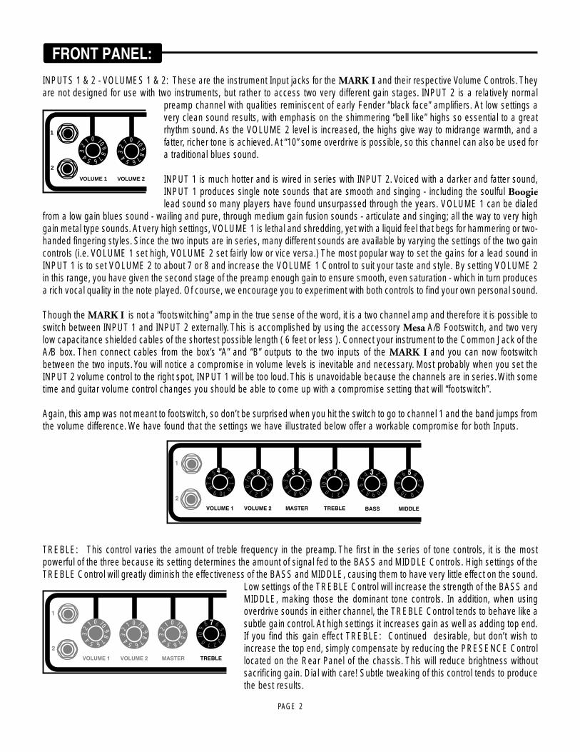
INPUTS 1 & 2 - VOLUMES 1 & 2: These are the instrument Input jacks for the MARK I and their respective Volume Controls. Theyare not designed for use with two instruments, but rather to access two very different gain stages. INPUT 2 is a relatively normal
preamp channel with qualities reminiscent of early Fender “black face” amplifiers. At low settings avery clean sound results, with emphasis on the shimmering “bell like” highs so essential to a greatrhythm sound. As the VOLUME 2 level is increased, the highs give way to midrange warmth, and afatter, richer tone is achieved. At “10” some overdrive is possible, so this channel can also be used fora traditional blues sound.
INPUT 1 is much hotter and is wired in series with INPUT 2. Voiced with a darker and fatter sound,INPUT 1 produces single note sounds that are smooth and singing - including the soulful Boogielead sound so many players have found unsurpassed through the years. VOLUME 1 can be dialed
from a low gain blues sound - wailing and pure, through medium gain fusion sounds - articulate and singing; all the way to very highgain metal type sounds. At very high settings, VOLUME 1 is lethal and shredding, yet with a liquid feel that begs for hammering or two-handed fingering styles. Since the two inputs are in series, many different sounds are available by varying the settings of the two gaincontrols (i.e. VOLUME 1 set high, VOLUME 2 set fairly low or vice versa.) The most popular way to set the gains for a lead sound inINPUT 1 is to set VOLUME 2 to about 7 or 8 and increase the VOLUME 1 Control to suit your taste and style. By setting VOLUME 2in this range, you have given the second stage of the preamp enough gain to ensure smooth, even saturation - which in turn producesa rich vocal quality in the note played. Of course, we encourage you to experiment with both controls to find your own personal sound.
Though the MARK I is not a “footswitching” amp in the true sense of the word, it is a two channel amp and therefore it is possible toswitch between INPUT 1 and INPUT 2 externally. This is accomplished by using the accessory Mesa A/B Footswitch, and two verylow capacitance shielded cables of the shortest possible length ( 6 feet or less ). Connect your instrument to the Common Jack of theA/B box. Then connect cables from the box’s “A” and “B” outputs to the two inputs of the MARK I and you can now footswitchbetween the two inputs. You will notice a compromise in volume levels is inevitable and necessary. Most probably when you set theINPUT 2 volume control to the right spot, INPUT 1 will be too loud. This is unavoidable because the channels are in series. With sometime and guitar volume control changes you should be able to come up with a compromise setting that will “footswitch”.
Again, this amp was not meant to footswitch, so don’t be surprised when you hit the switch to go to channel 1 and the band jumps fromthe volume difference. We have found that the settings we have illustrated below offer a workable compromise for both Inputs.
TREBLE: This control varies the amount of treble frequency in the preamp. The first in the series of tone controls, it is the mostpowerful of the three because its setting determines the amount of signal fed to the BASS and MIDDLE Controls. High settings of theTREBLE Control will greatly diminish the effectiveness of the BASS and MIDDLE, causing them to have very little effect on the sound.
Low settings of the TREBLE Control will increase the strength of the BASS andMIDDLE, making those the dominant tone controls. In addition, when usingoverdrive sounds in either channel, the TREBLE Control tends to behave like asubtle gain control. At high settings it increases gain as well as adding top end.If you find this gain effect TREBLE: Continued desirable, but don’t wish toincrease the top end, simply compensate by reducing the PRESENCE Controllocated on the Rear Panel of the chassis. This will reduce brightness withoutsacrificing gain. Dial with care! Subtle tweaking of this control tends to producethe best results.
PAGE 3
FRONT PANEL: (Continued)
1
2
VOLUME 2 TREBLEMASTERVOLUME 1
2
56 7 8
10
109
34
BASS
2
5 678
1 0 109
34
2
5 678
1 0 109
34
2
5 678
1 0 109
34
2
5 678
1 0 109
34
2
5678
1
010
934
MIDDLE
1
2
VOLUME 2 TREBLEMASTERVOLUME 1 BASS
2
5 678
1 0 109
34
2
5 678
1 0 109
34
2
5 678
1 0 109
34
2
5 678
1 0 109
34
2
5 678
1 0 109
34
POWER
60 RMS STANDBY TWEED
MARK I
ON100 RMS
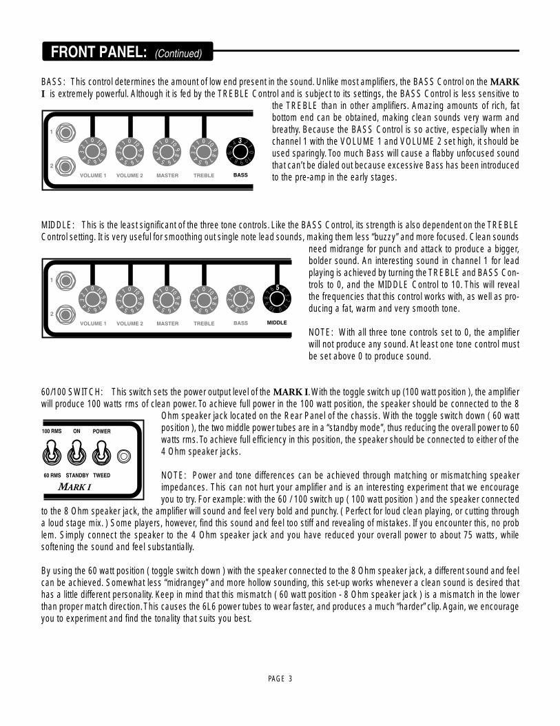
BASS: This control determines the amount of low end present in the sound. Unlike most amplifiers, the BASS Control on the MARKI is extremely powerful. Although it is fed by the TREBLE Control and is subject to its settings, the BASS Control is less sensitive to
the TREBLE than in other amplifiers. Amazing amounts of rich, fatbottom end can be obtained, making clean sounds very warm andbreathy. Because the BASS Control is so active, especially when inchannel 1 with the VOLUME 1 and VOLUME 2 set high, it should beused sparingly. Too much Bass will cause a flabby unfocused soundthat can’t be dialed out because excessive Bass has been introducedto the pre-amp in the early stages.
MIDDLE: This is the least significant of the three tone controls. Like the BASS Control, its strength is also dependent on the TREBLEControl setting. It is very useful for smoothing out single note lead sounds, making them less “buzzy” and more focused. Clean sounds
need midrange for punch and attack to produce a bigger,bolder sound. An interesting sound in channel 1 for leadplaying is achieved by turning the TREBLE and BASS Con-trols to 0, and the MIDDLE Control to 10. This will revealthe frequencies that this control works with, as well as pro-ducing a fat, warm and very smooth tone.
NOTE: With all three tone controls set to 0, the amplifierwill not produce any sound. At least one tone control mustbe set above 0 to produce sound.
60/100 SWITCH: This switch sets the power output level of the MARK I. With the toggle switch up (100 watt position ), the amplifierwill produce 100 watts rms of clean power. To achieve full power in the 100 watt position, the speaker should be connected to the 8
Ohm speaker jack located on the Rear Panel of the chassis. With the toggle switch down ( 60 wattposition ), the two middle power tubes are in a “standby mode”, thus reducing the overall power to 60watts rms. To achieve full efficiency in this position, the speaker should be connected to either of the4 Ohm speaker jacks.
NOTE: Power and tone differences can be achieved through matching or mismatching speakerimpedances. This can not hurt your amplifier and is an interesting experiment that we encourageyou to try. For example: with the 60 / 100 switch up ( 100 watt position ) and the speaker connected
to the 8 Ohm speaker jack, the amplifier will sound and feel very bold and punchy. ( Perfect for loud clean playing, or cutting througha loud stage mix. ) Some players, however, find this sound and feel too stiff and revealing of mistakes. If you encounter this, no problem. Simply connect the speaker to the 4 Ohm speaker jack and you have reduced your overall power to about 75 watts, whilesoftening the sound and feel substantially.
By using the 60 watt position ( toggle switch down ) with the speaker connected to the 8 Ohm speaker jack, a different sound and feelcan be achieved. Somewhat less “midrangey” and more hollow sounding, this set-up works whenever a clean sound is desired thathas a little different personality. Keep in mind that this mismatch ( 60 watt position - 8 Ohm speaker jack ) is a mismatch in the lowerthan proper match direction. This causes the 6L6 power tubes to wear faster, and produces a much “harder” clip. Again, we encourageyou to experiment and find the tonality that suits you best.

PAGE 4
POWER
STANDBY TWEED
MARK I
ON
POWER
STANDBY TWEED
MARK I
ON
STANDBY SWITCH: The STANDBY switch turns off the high voltages in your Boogie, while allowing it to idle, keeping the tubefilaments warm. It should be used during power-up to keep from “shocking” cold power tubes. Simply flip the POWER switch to the ON
position while leaving the STANDBY switch in the standby position (toggle down) for about a minute.
This reduces the strain on your power tubes and prolongs their toneful life substantially. Standby modeshould also be used during breaks in playing, as it produces less strain on tubes if they are kept warm,rather than turned completely on and off with every use.
POWER / TWEED SWITCH: This is the A.C. power switch for the MARK I and is unique in that it offers two modes of operation:NORMAL and TWEED. With the toggle switch up ( Power ), the amplifier operates like usual amplifiers: at the voltage rating present
at the wall socket ( normally between 110 and 120 volts in the United States ). With the toggle switch inthe TWEED position ( Down ), your Boogie becomes a unique and extremely versatile tone machine!Over the last decade we have put strong emphasis on not only the sound of our instruments, but on theway they respond to you as you play. TWEED is the ultimate example of this. By using a speciallydesigned tapped transformer, we were able to lower voltages across the circuit at will. This endows theamplifier with the best qualities of the early “tweed” amps of the 50’s, so sought after for their sweet,warm tone and spongy, elastic feel.
(Their weak, sagging power supplies just weren’t capable of the efficiency inherent in the modern amplifiers of today.) These vintagegems of yesteryear are wonderful to play at home or in the studio, but not too reliable or practical for everyday gig use. The specialtapped transformer of the MARK I combines the sound and feel of these vintage classics with necessary reliability found in moderndesign and construction. For everyday use in larger clubs or when you need lots of clean headroom, the NORMAL position is perfect.When you find yourself in that tiny barroom situation, where even the 60 watt power position gets you dirty looks from the bartender,simply switch to TWEED and you’ll both be happy. Likewise, if you find yourself in the studio needing a vintage sound with lots ofpower section overdrive, try TWEED. This feature is invaluable for late night practicing, or recording around the house. You’ll bewailing with the sound you’ve always dreamt of, while the next-door neighbors are fast asleep.
With the POWER switch in the TWEED position, it is also possible to utilize different types of power tubes for different sounds, stylesand feels. In this position, the MARK I can be used with not only the standard 6L6 type tubes, but also 6V6 and EL34 power tubesas well. Using these three types of power tubes, three very distinct personalities can be achieved. With the standard 6L6 tubes inplace, the amp is most versatile - warm and rich sounding, yet capable of delivering full power for lots of clean headroom. These tubescan be used in either the NORMAL ( switch up ) POWER position, or the TWEED ( switch down ) position for a softer sweeter sound.Installing the smaller 6V6 power tubes ( most often seen in the classic Fender Deluxe amps ) produces a sound that is vintage andbeyond. Wonderful for blues dates or the recording studio, these tubes create a sweet, round, yet bubbly sound. Easy to drive to clip,they are a favorite of many die-hard bluesmen with their emotional, explosive style of attack. In the 100 watt position with the TWEEDswitch down, the amplifier produces roughly 40 watts and roughly half that in the 60 watt position. This is possibly one of the mostenjoyable features of the MARK I and we strongly encourage you to try these various tubes.
REMEMBER...Only use the 6V6 tubes with the POWER switch in the TWEED ( down ) position. Using them in the POWER switch( Up ) position will cause them to burn out rapidly! For a proper impedance match when using 6V6 power tubes, the internal combospeaker should be connected to the 4 OHM SPEAKER JACK or used with a 16 Ohm speaker cabinet on the 8 OHM SPEAKERJACK. With the 60 / 100 switch in the 60 watt position, the 8 OHM SPEAKER JACK becomes a 32 Ohm jack and the 4 Ohm jackbecomes a 16 Ohm jack. Again, mismatching in the lower than proper impedance direction will cause power tubes to wear faster andsound somewhat “harsher”.
FRONT PANEL: (Continued)

PAGE 5
REAR PANEL:
FUSE
3A
FUSE
3A GROUND
FX LEVEL
POWER / TWEED SWITCH: Continued From hard rock to insane metal, the MARK I can be your essential ingredient toachieving any tone imaginable! Those players who want that British “crunch” tone can try replacing the output tubes with fourEuropean - style EL34 power tubes. Greatly enhanced, shredding top end and the grinding lows so important to a great metal soundresult from this tube change. And yet all the fluid, spongy feel remains intact for those hammer-ons, pull-offs, or those two-handedfingering lines that become noticeably effortless as the gain controls are increased. With EL34 power tubes in place, rated power isroughly 80 watts in the switch up ( 100 watt ) position and about half of that in the switch down ( 60 watt ) position. It is easy to obtainthe right grind at virtually any volume level. A metal player’s dream, the MARK I boasts gain and tone that put the “Modified” Britishheads to shame and it does so reliably and consistently!
AC RECEPTACLE: This grounded outlet provides A.C. power for effects and other powered devices that require 117 volts. It isactive whenever the amplifier’s A.C. power cord is plugged into the wall and is not affected by the POWER /TWEED switch located on the Front Panel.
FUSE: This is the A.C. line fuse for your Boogie. Should the fuse ever blow, be sure to replace it with the same rating in a SLO-BLOtype package. Domestic U.S. versions of the MARK I, require a 3 amp SLO-BLO Fuse. By far the most common cause of a blownfuse is a bad power tube. Always follow the cold start procedure mentioned earlier in the ON / STANDBY switch section and watch the
power tubes as you flip the STANDBY switch to the ON position. If a power tube is going bad or isarcing you will see it! Flip the STANDBY switch to standby immediately and replace the faulty powertube (s) and the fuse if necessary. If you see nothing abnormal as you lift the STANDBY switch, it ispossible that a power tube shorted temporarily and blew the Fuse. If this is the case it may workagain normally. To be extra safe you may want to replace all power tubes in the “shotgun” trouble-shooting tradition and save the replaced set as spares. Always carry along a few extra fuses andtubes, they could be worth their weight in gold when needed.
GROUND: This three position switch reverses the ground of your Boogie. It is often helpful in reducing annoying buzz and humwhich originate in the A.C. power wiring outside the amplifier. We recommend leaving the switch in it’s center ( OFF ) position, unless
position A or B definitely helps cure noise problems. In the center OFF position, yourBoogie cannot be the source of annoying microphone “ground shocks”.
FRONT PANEL: (Continued)
PAGE 6
REAR PANEL: (Continued)
FUSE
3A GRND SLAVE LOOP
FX LEVEL FX LEVEL
OUT IN
2
5 678
1 0 109
34
FUSE
3A GRND SLAVE
FX LEVEL FX LEVEL
OUT IN
2
5 678
1 0 109
34
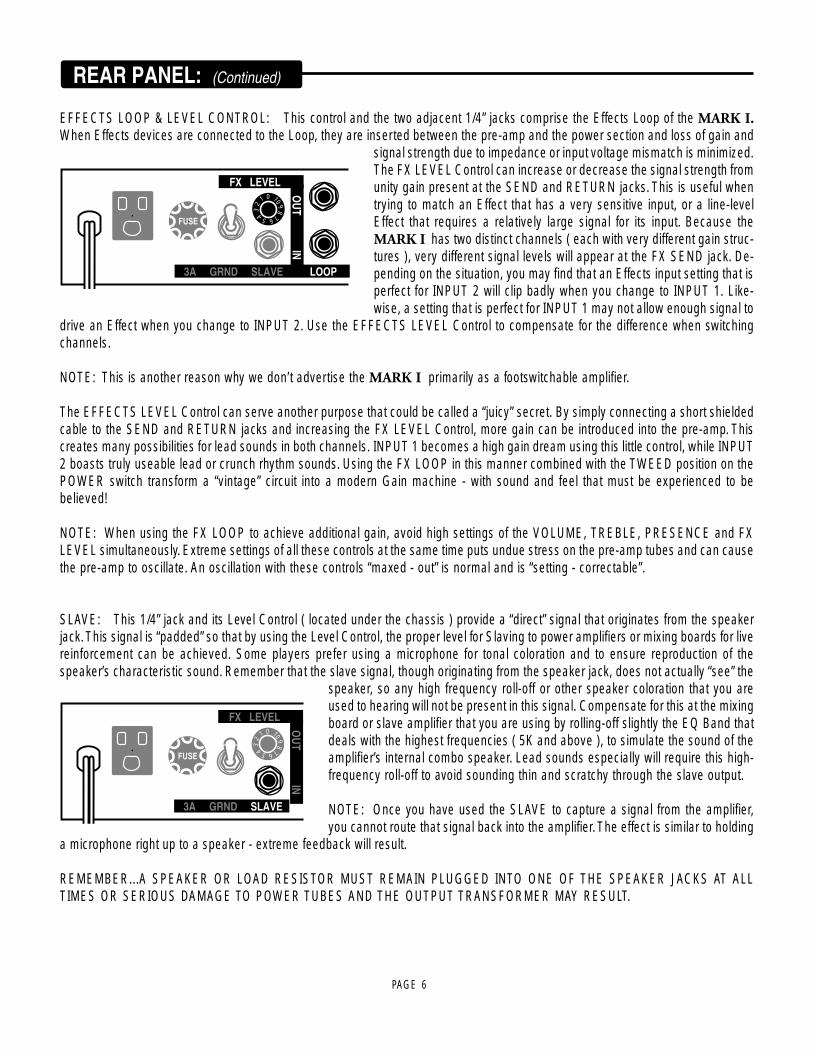
EFFECTS LOOP & LEVEL CONTROL: This control and the two adjacent 1/4” jacks comprise the Effects Loop of the MARK I.When Effects devices are connected to the Loop, they are inserted between the pre-amp and the power section and loss of gain and
signal strength due to impedance or input voltage mismatch is minimized.The FX LEVEL Control can increase or decrease the signal strength fromunity gain present at the SEND and RETURN jacks. This is useful whentrying to match an Effect that has a very sensitive input, or a line-levelEffect that requires a relatively large signal for its input. Because theMARK I has two distinct channels ( each with very different gain struc-tures ), very different signal levels will appear at the FX SEND jack. De-pending on the situation, you may find that an Effects input setting that isperfect for INPUT 2 will clip badly when you change to INPUT 1. Like-wise, a setting that is perfect for INPUT 1 may not allow enough signal to
drive an Effect when you change to INPUT 2. Use the EFFECTS LEVEL Control to compensate for the difference when switchingchannels.
NOTE: This is another reason why we don’t advertise the MARK I primarily as a footswitchable amplifier.
The EFFECTS LEVEL Control can serve another purpose that could be called a “juicy” secret. By simply connecting a short shieldedcable to the SEND and RETURN jacks and increasing the FX LEVEL Control, more gain can be introduced into the pre-amp. Thiscreates many possibilities for lead sounds in both channels. INPUT 1 becomes a high gain dream using this little control, while INPUT2 boasts truly useable lead or crunch rhythm sounds. Using the FX LOOP in this manner combined with the TWEED position on thePOWER switch transform a “vintage” circuit into a modern Gain machine - with sound and feel that must be experienced to bebelieved!
NOTE: When using the FX LOOP to achieve additional gain, avoid high settings of the VOLUME, TREBLE, PRESENCE and FXLEVEL simultaneously. Extreme settings of all these controls at the same time puts undue stress on the pre-amp tubes and can causethe pre-amp to oscillate. An oscillation with these controls “maxed - out” is normal and is “setting - correctable”.
SLAVE: This 1/4” jack and its Level Control ( located under the chassis ) provide a “direct” signal that originates from the speakerjack. This signal is “padded” so that by using the Level Control, the proper level for Slaving to power amplifiers or mixing boards for livereinforcement can be achieved. Some players prefer using a microphone for tonal coloration and to ensure reproduction of thespeaker’s characteristic sound. Remember that the slave signal, though originating from the speaker jack, does not actually “see” the
speaker, so any high frequency roll-off or other speaker coloration that you areused to hearing will not be present in this signal. Compensate for this at the mixingboard or slave amplifier that you are using by rolling-off slightly the EQ Band thatdeals with the highest frequencies ( 5K and above ), to simulate the sound of theamplifier’s internal combo speaker. Lead sounds especially will require this high-frequency roll-off to avoid sounding thin and scratchy through the slave output.
NOTE: Once you have used the SLAVE to capture a signal from the amplifier,you cannot route that signal back into the amplifier. The effect is similar to holding
a microphone right up to a speaker - extreme feedback will result.
REMEMBER...A SPEAKER OR LOAD RESISTOR MUST REMAIN PLUGGED INTO ONE OF THE SPEAKER JACKS AT ALLTIMES OR SERIOUS DAMAGE TO POWER TUBES AND THE OUTPUT TRANSFORMER MAY RESULT.
PAGE 7
REAR PANEL: (Continued)
FUSE
3A GRND SLAVE LOOP PRES
FX LEVEL FX LEVEL
OUT IN
2
5 678
1 0 109
34 2
5 678
1 0 109
34
FUSE
3A GRND SLAVE LOOP PRES REV
FX LEVEL FX LEVEL
OUT IN
2
5 678
1 0 109
34 2
5 678
1 0 109
34
2
5 678
1 0 109
34
SPKRS
2
5 678
1 0 109
34
8 4 4
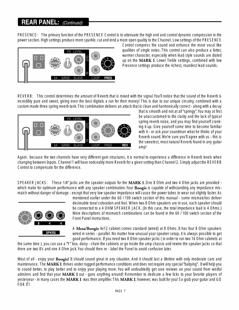
PRESENCE: The primary function of the PRESENCE Control is to attenuate the high end and control dynamic compression in thepower section. High settings produce more sparkle, cut and lend a more open quality to the Channel. Low settings of the PRESENCE
Control compress the sound and enhance the more vocal likequalities of single notes. This control can also produce a fatter,warmer character, especially when lead style sounds are dialedup on the MARK I. Lower Treble settings, combined with lowPresence settings produce the richest, roundest lead sounds.
REVERB: This control determines the amount of Reverb that is mixed with the signal. You’ll notice that the sound of the Reverb isincredibly pure and sweet, giving even the best digitals a run for their money! This is due to our unique circuitry, combined with acustom-made three spring reverb tank. This combination delivers an attack that is clean and harmonically correct - along with a decay
that is smooth and not at all “springy”. You may at firstbe unaccustomed to the clarity and the lack of typicalspring reverb noise, and you may find yourself crank-ing it up. Give yourself some time to become familiarwith it - or ask your soundman what he thinks of yourReverb sound. We’re sure you’ll agree with us - this isthe sweetest, most natural Reverb found in any guitaramp!
Again: because the two channels have very different gain structures, it is normal to experience a difference in Reverb levels whenchanging between Inputs. Channel 1 will have noticeably more Reverb for a given setting than Channel 2. Simply adjust the REVERBControl to compensate for the difference.
SPEAKER JACKS: These 1/4” jacks are the speaker outputs for the MARK I. One 8 Ohm and two 4 Ohm jacks are provided -which make for optimum performance with any speaker combination. Your Boogie is capable of withstanding any impedance mis-match without danger of damage - except that very low speaker impedance will cause the power tubes to wear out slightly faster. As
mentioned earlier under the 60 / 100 switch section of this manual - some mismatches deliverdesireable tonal coloration and feel. When two 8 Ohm speakers are in use, each speaker shouldbe connected to a 4 OHM SPEAKER JACK. (In this case, the total impedance load is 4 Ohms.)More descriptions of mismatch combinations can be found in the 60 / 100 switch section of theFront Panel instructions.
A Mesa/Boogie 4x12 cabinet comes standard (wired) at 8 Ohms. It has four 8 Ohm speakerswired in series - parallel. No matter how unusual your speaker setup, it is always possible to getgood performance. If you need two 8 Ohm speaker jacks ( in order to run two 16 Ohm cabinets at
the same time ), you can use a “Y” box, daisy - chain the cabinets or go inside the amp chassis and rewire the speaker jacks so thatthere are two 8’s and one 4 Ohm jack. You should then re - label the Panel to avoid confusion later.
Most of all - enjoy your Boogie! It should sound great in any situation. And it should last a lifetime with only moderate care andmaintenance. The MARK I thrives under rugged performance conditions and does not require any special “babying”. It will help youto sound better, to play better and to enjoy your playing more. You will undoubtedly get rave reviews on your sound from wistfuladmirers and find that your MARK I out - guns anything around! Remember to dedicate a few licks to your favorite players ofyesteryear - in many cases the MARK I was their amplifier. This MARK I, however, was built for you! So grab your guitar and GOFOR IT!
GRAYREVERBWHITE
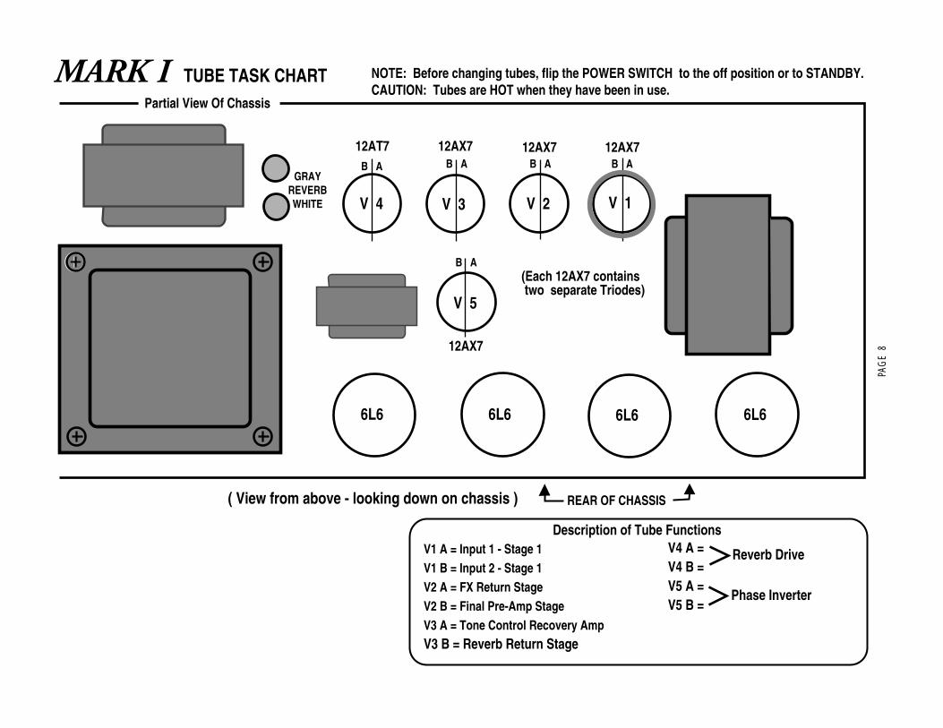
TUBE TASK CHARTMARK I
V 5
NOTE: Before changing tubes, flip the POWER SWITCH to the off position or to STANDBY. CAUTION: Tubes are HOT when they have been in use.
Partial View Of Chassis
(Each 12AX7 contains two separate Triodes)
V 2V 3V 4 V 1
B A B AB A B A
REAR OF CHASSIS ( View from above - looking down on chassis )
6L6 6L6 6L6 6L6
12AX7 12AX7 12AX7
12AX7
B A
12AT7
V1 A = Input 1 - Stage 1V1 B = Input 2 - Stage 1V2 A = FX Return StageV2 B = Final Pre-Amp StageV3 A = Tone Control Recovery AmpV3 B = Reverb Return Stage
V4 A = V4 B =V5 A =V5 B =
Description of Tube Functions
Reverb Drive
Phase Inverter
PAG
E 8
VOLUME 2 MASTERVOLUME 1 BASS MIDDLE
POWER
60 RMS STANDBY TWEED
MARK I
ON100 RMS
1
2
TREBLE
VOLUME 2 MASTERVOLUME 1 BASS MIDDLE
POWER
60 RMS STANDBY TWEED
MARK I
ON100 RMS
1
2
TREBLE
VOLUME 2 MASTERVOLUME 1 BASS MIDDLE
POWER
60 RMS STANDBY TWEED
MARK I
ON100 RMS
1
2
TREBLE
VOLUME 2 MASTERVOLUME 1 BASS MIDDLE
POWER
60 RMS STANDBY TWEED
MARK I
ON100 RMS
1
2
TREBLE
VOLUME 2 MASTERVOLUME 1 BASS MIDDLE
POWER
60 RMS STANDBY TWEED
MARK I
ON100 RMS
1
2
TREBLE
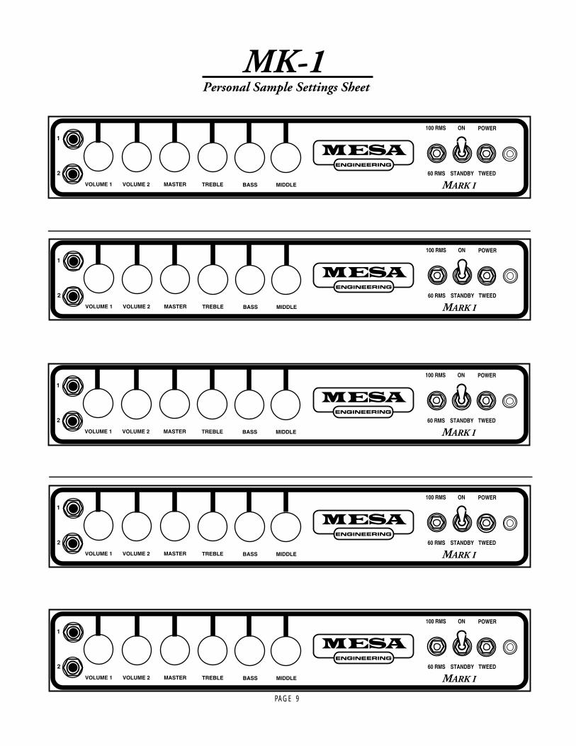
MK-1 Personal Sample Settings Sheet
PAGE 9
PAGE 10
TUBE MAINTENANCE & MICROPHONICS:You may occasionally experience some form of tube noise or microphonics. Certainly no cause for alarm, this quirky behavior comeswith the territory and the Tone. Much like changing a light bulb, you don’t need a technician to cure these types of minor userserviceable annoyances and in fact, you’ll be amazed at how easy it is to cure tube problems...by simply swapping out a pre-amp orpower tube!
First may we suggest that you set the amplifier up on something so that you can get to the tubes comfortably without having to benddown. It also helps to have adequate lighting as you will need to see the tube sockets clearly to swap tubes. Use Caution andcommon sense when touching the tubes after the amplifier has been on as they May Be Extremely Hot! If they are hot and you don’twant to wait for them to cool off, try grasping them with a rag and also note that the glass down around the bulbous silvery tip isconsiderably less hot which makes it easier to handle. Gently rock the tube back and forth as you pull it away from its socket.
DIAGNOSING POWER TUBE PROBLEMS:There are two main types of tube faults: shorts and noise. Both large and small tubes may fall prey to either of these problems butdiagnosis and remedy is usually simple.
If a fuse blows, the problem is most likely a shorted power tube, Shorts can either be mild or severe. In a mildly shorted tube theelectron flow has overcome the control grid and excess current flows to the plate. You will usually hear the amp become distorted andbegin to hum slightly. If this occurs, quickly look at the power tubes as you switch the amp to STANDBY and try to identify one asglowing red hot. It is likely that two of a pair will be glowing since the “shorted” tube will pull down the bias for its adjacent mates, butone tube may be glowing hotter — and that one is the culprit. The other two are often fine — unless they’ve been glowing bright redfor several minutes.
Because there is no physical short inside the tube (just electrons rioting out of control) merely switching to STANDBY for a fewmoments then back to OPERATE will usually cure the problem... at least temporarily. Watch the tubes carefully now. Should theproblem recur, the intermittent tube will visibly start to over heat before the others and thus it can be identified. It should be replacedwith one from the same color batch, shown on its label. Call us and we will send one out to you.
The severe short is not nearly so benign. In the worst cases, a major arcing short occurs between the plate and the cathode withvisible lightning inside the glass and a major noise through the speaker. If this is seen to happen, IMMEDIATELY turn the amp toSTANDBY. By this time the fuse probably will have blown. Such a short is usually caused by a physical breakdown inside the tubeincluding contaminate coming loose or physical contact (or near contact) between the elements. Replace it and the fuse with theproper slo-blo type and power up the amp using the power up procedure as we described earlier in this manual.
TUBE NOISE:Often caused by contamination within in a tube, the culprit can usually be identified, and by lightly tapping on the glass, you willprobably hear the noise change. Hearing some noise through the speakers while tapping on the 12AX7’s is normal however. And theone nearer the input will always sound louder because its output is being further amplified by the second 12AX7.
The power tubes should be all but quiet when they are tapped. If crackling or hissing changes with the tapping, you have probablyfound the problem. To confirm a noisy power tube, merely put the MARK I on STANDBY, remove it from its socket and turn it backon. It will cause no damage to run the MARK I briefly with one power tube missing. You may notice a slight background hum,however, as the push-pull becomes unbalanced. Whenever you are trying to diagnose a suspect tube, keep your other hand ON thePower and Standby switches ready to shut them off instantly in the unlikely case you provoke a major short.
If you think you’ve located a problem tube but aren’t sure, we recommend substituting the suspect with a new one just to be sure ofyour diagnoses. You will be doing yourself and us a big favor by just following the simple guidelines previously mentioned regardingtube replacement. You’ll probably be successful with much less effort than is required to disconnect everything and haul the unit to atechnician who will basically perform the same simple tests. If the tubes are still within their six-month warranty period, we will happilysend you a replacement. Just note the color designation on the tube label so that we can send you the appropriate match.

PAGE 11
DIAGNOSING PRE AMP TUBE PROBLEMS:Because your amplifier is an all tube design, it is quite possible that you will at some point experience minor pre-amp tube noise. Restassured - this is no cause for alarm and you can take care of the problem yourself in a matter of minutes by simply swapping tubes
Let us begin by saying; It is a “very good” idea to keep at least a couple of spare pre-amp tubes on hand at all times to insureuninterrupted performance. These minor pre-amp tube problems can take many forms but can generally be described in two catego-ries: Noise and Microphonics, Noise can be in the form of crackling, sputtering, white noise/hiss and/or hum. Microphonic problemsusually appear in the form of a ringing or high pitched squealing that gets worse as the gain or volume is increased thus are morenoticeable in the higher gain Lead modes. Microphonic problems are easily identified because the problem is still present even withthe instruments’ volume off or unplugged altogether - unlike pick-up feedback which ceases as the instrument is turned down. Micro-phonic noise is caused by mechanical vibration and shock: think of banging a microphone around and you’ll understand where theword came from.
The best way to approach a pre-amp tube problem is to see if it occurs only in one specific mode or channel. Then refer to the TubeTask Chart found on page page 8 and it should lead you to the tube needing replacement. Then all that remains is to swap the suspecttube for a known good performer.
If you cannot narrow down the trouble to a specific mode or channel, the problem may be the small tube that drives the power tubeswhich is operational in all modes and channels. Though rare, a problem with the driver tube would show up in all aspects of perfor-mance - so if you can’t narrow the problem down to being mode or channel specific, you may want to try replacing the driver tubeDriver problems generally show themselves in the form of crackling or hum in all modes of performance and/or weak overall outputfrom the amplifier. Occasionally an anemic driver tube will cause the amplifier to sound flat and lifeless, but this is somewhatuncommon, as worn power tubes are a more likely suspect for this type of problem.
Sometimes making the diagnosis is more trouble than it’s worth and it’s faster and easier to merely replace the small preamp tubesONE AT A TIME with a replacement known to be good. But MAKE SURE you keep returning the tubes to their original socket until youhit the one that cures the problem. You’ll notice that tubes located nearer to the Input jack always sound noisier...but this is becausethey are at the start of the chain and their noise gets amplified over and over by the tubes that follow. The tube that goes into this“input socket” (usually labled V1) needs to be the least noisy of the bunch. The tube that goes at the end of the preamp chain - justahead of the power tubes - can be quite noisy without causing any problem at all. The tubes in your amp have already been locatedin the most appropriate sockets and this is why you should NEVER pull them all out at once and ALWAYS swap them one at a timeALWAYS return a perfectly good tube to its original socket. Also it’s a good idea to put the amp on Standby when swapping tubes toreduce the heat build up in the tubes themselves and to prevent explosive noises (which can still occur even if you are pulling thetubes away from their sockets gently) from coming through the speaker.
Remember, take your time, be patient and chances are real good that you can fix your amp yourself by finding and replacing the badtube. It kills us to see someone who has shipped their amp back to us...and all it needed was a simple tube replacement! If you mustsend back your amp, unplug the power cord, speaker and reverb cables then remove the chassis from the cabinet by unscrewing thefour mounting bolts on top. The chassis then slides back like a drawer and comes out. Remove the big power tubes and mark themaccording to their location from left to right 1, 2 etc. They need to be wrapped separately with plenty of wadded up newspaper aroundthem and put in a smaller box within the larger carton. To wrap the chassis, use plenty of tightly wadded up newspaper so there is atleast six inches of “crush space” between the chassis and the cardboard box. Bubble wrap also works well but please DON’T usestyrene peanuts - they will shift during transit and get lodged inside your electronics as well as allowing your amp to end up at thebottom of the box unprotected and possibly damaged. Preamp tubes don’t normally wear out as a rule. Therefore, it is not a good ideato change them just for the sake of changing them. If there isn’t a problem - don’t fix it. If there is no result from your substitutions, itmay be possible that you have more than one problematic tube. Though rare, this does happen and though it makes the troubleshoot-ing process a little more intimidating, it is still possible to cure the problem yourself.
NOTE: It is normal to hear a slight metallic ringing sound when tapping on the preamp tubes. As long as the tube does not break intooscillation or start crackling or any other form of bizzare noise, it is considered normal and functional.

PAGE 12
SPEAKER IMPEDANCE MATCHING & HOOK-UP GUIDE:
IMPEDANCE:Wiring up speakers to provide the most effective load and making sure that all of them are in phase will help in creating the best soundpossible. This is not too difficult, as long as you understand a few things about loading and how to connect your speakers to providean optimal resistive load.
Mesa Boogie amplifiers can handle 4 and 8 ohms effectively. Never run below 4 ohms in a tube amplifier unless you are absolutelycertain that the system can handle it properly; this can cause damage to the Output transformer. A few amplifiers can handle 2 ohmseffectively without damaging them ( for example the Mesa’s Bass 400+ ). You can always have a higher resistance ( 16 ohms, forexample ) without damaging results, but too low of a resistance will likely cause problems.
MIS-MATCHING:When running a higher resistance ( for example: 8 ohm output into 16 ohm cabinet ), a slightly different feel and response will beeminent. A slight mismatch can provide a darker smoother tone with a little less output and attack. This response is a result of theamplifier running a bit cooler. Sometimes when using more than one cabinet a mismatch will be the only option.
WHAT IS MY CABINETS IMPEDANCE:If you have only a single speaker, you just match that single speakers impedance to the amplifier, and you are done. In many cases,you will have a number of speakers, and then you must calculate the “load” that the amplifier will need to support. There are generallythree ways to wire multiple speakers together. They are as follows:
SERIES:When you wire ( hook-up ) speakers in Series, the speakers resistance ( as measured in ohms ) is additive - i.e. putting two 8 ohmspeakers in Series results in a 16 ohm load.
Speaker A = 8 Ohms Speaker B = 8 Ohms
SERIES: Connect the Negative side of Speaker Ato the Positive side of Speaker B
POSITIVE = NEGATIVE =
Made byElectro-Voice
BLACK SHAD
OW
Made byElectro-Voice
BLAC
K SHADOW

PAGE 13
SPEAKER IMPEDANCE MATCHING & HOOK-UP GUIDE: (Continued)
PARALLEL:When wiring in parallel, the resistance of the speakers decreases. Two 8 ohm speakers wired in ( hooked-up ) Parallel results in a 4ohm load. It’s easy to calculate the effect of a resistive load when all the speakers are all the same resistance. It is really not suggestedto wire different resistive load values in Parallel ( 8 and 4, 16 and 8 etc. ) The formula for figuring the total impedance in Parallel is themultiplication of the two loads divided by the sum of the two loads - i.e. putting two 8 ohm speakers in Parallel results in a 4 ohm load.Connect the Positive side of Speaker A to the Positive side of Speaker B - Connect the Negative side of Speaker A to the Negativeside of Speaker B.
COMBINATION OF SERIES & PARALLEL:This is really just two sets of Parallel wired speakers connected in series. This is how you maintain a consistent load with multiplespeakers. The importance of this is more evident when you have more than one cabinet to connect to your amplifier. This is when you
need to figure out the loads and how to wire them up withoutapplying too low of a resistance on the amplifier.
Simply connect the Positive side of Speaker A to the Posi-tive side of Speaker C.
Connect the Negative side of Speaker A to the Positive sideof Speaker B, then on to the Positive side of Speaker D andfinally on to the Negative side of Speaker C.
And lastly, connect the Negative side of Speaker B to theNegative side of Speaker D.
4 Eight ( 8 ) Ohm speakers wired in Series Parallel = a TotalLoad of 8 Ohms.
POSITIVE
Speaker A8 Ohms
Speaker B8 Ohms
NEGATIVE
Total Load = 4 Ohms
Made byElectro-Voice
BLAC
K SHADOWMade by
Electro-Voice
BLAC
K SHADOW
Made byElectro-Voice
BLAC
K SHADOW
Made byElectro-Voice
BLAC
K SHADOWMade by
Electro-Voice
BLAC
K SHADOW
Made byElectro-Voice
BLAC
K SHADOW
SPEAKER A SPEAKER B
SPEAKER C SPEAKER D
NEGATIVE
All 4 Spkrs.are 8 Ohms
POSITIVE

1 2
54
4 Ohm Cabinet
3
8 OHM 4 OHM 4 OHM
Partial back view of some Mesa amp
8 Ohm CabinetSAFE MISMATCH
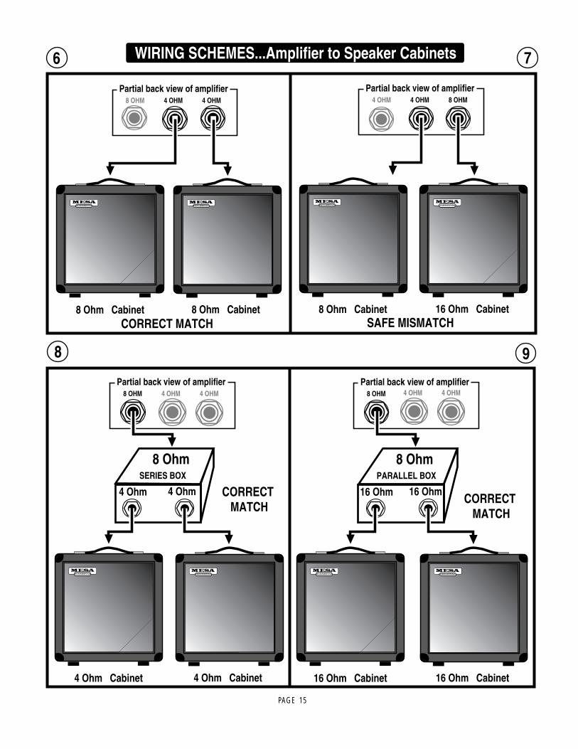
WIRING SCHEMES...Amplifier to Speaker Cabinets
4 OHM 8 OHM 16 OHM
Partial back view of amplifier
16 Ohm Cabinet
4 OHM 8 OHM 16 OHM
Partial back view of amplifier
16 Ohm CabinetSAFE MISMATCH
8 OHM 4 OHM 4 OHM
Partial back view of amplifier8 OHM 4 OHM 4 OHM
Partial back view of amplifier
8 Ohm Cabinet
4 Ohm Cabinet8 Ohm Cabinet
PAGE 14
8 OHM 4 OHM 4 OHM
Partial back view of amplifier
8 Ohm Cabinet 8 Ohm Cabinet
6
8 Ohm Cabinet 16 Ohm Cabinet
8
4 OHM 4 OHM 8 OHM
Partial back view of amplifier
SAFE MISMATCH
8 OHM
Partial back view of amplifier
SERIES BOX
8 Ohm
4 Ohm 4 Ohm
4 Ohm Cabinet 4 Ohm Cabinet
4 OHM 4 OHM 8 OHM
Partial back view of amplifier
PARALLEL BOX
8 Ohm
16 Ohm 16 Ohm
16 Ohm Cabinet 16 Ohm Cabinet
9
4 OHM 4 OHM
7 WIRING SCHEMES...Amplifier to Speaker Cabinets
CORRECT MATCH
CORRECT MATCH
CORRECT MATCH
PAGE 15

4 OHM 4 OHM 8 OHM
Partial back view of amplifier
8 Ohm Cabinet 8 Ohm Cabinet
SERIES BOX
16 Ohm
8 Ohm 8 Ohm
8 Ohm Cabinet
10
SAFE MISMATCH
12
4 OHM 4 OHM
Partial back view of amplifier
16 Ohm Cabinet 16 Ohm Cabinet
11
8 OHM
8 Ohm Cabinet
16 Ohm Cabinet 16 Ohm Cabinet
4 OHM4 OHM8 OHM
Partial back view of amp
PARALLEL BOX
8 Ohm
16 Ohm 16 Ohm
WIRING SCHEMES...Amplifier to Speaker Cabinets
CORRECT MATCH
SAFE MISMATCHPAGE 16

4 OHM 4 OHM 8 OHM
Partial back view of amplifier
8 Ohm Cabinet 8 Ohm Cabinet
SERIES BOX
16 Ohm
8 Ohm 8 Ohm
16 Ohm Cabinet
13
SAFE MISMATCH
WIRING SCHEMES...Amplifier to Speaker Cabinets
4 OHM4 OHM8 OHM
Partial back view of amplifier
16 Ohm Cabinet 16 Ohm Cabinet
PARALLEL BOX
8 Ohm
16 Ohm 16 Ohm
16 Ohm Cabinet
SAFE MISMATCH
14
PAGE 17
PAGE 18
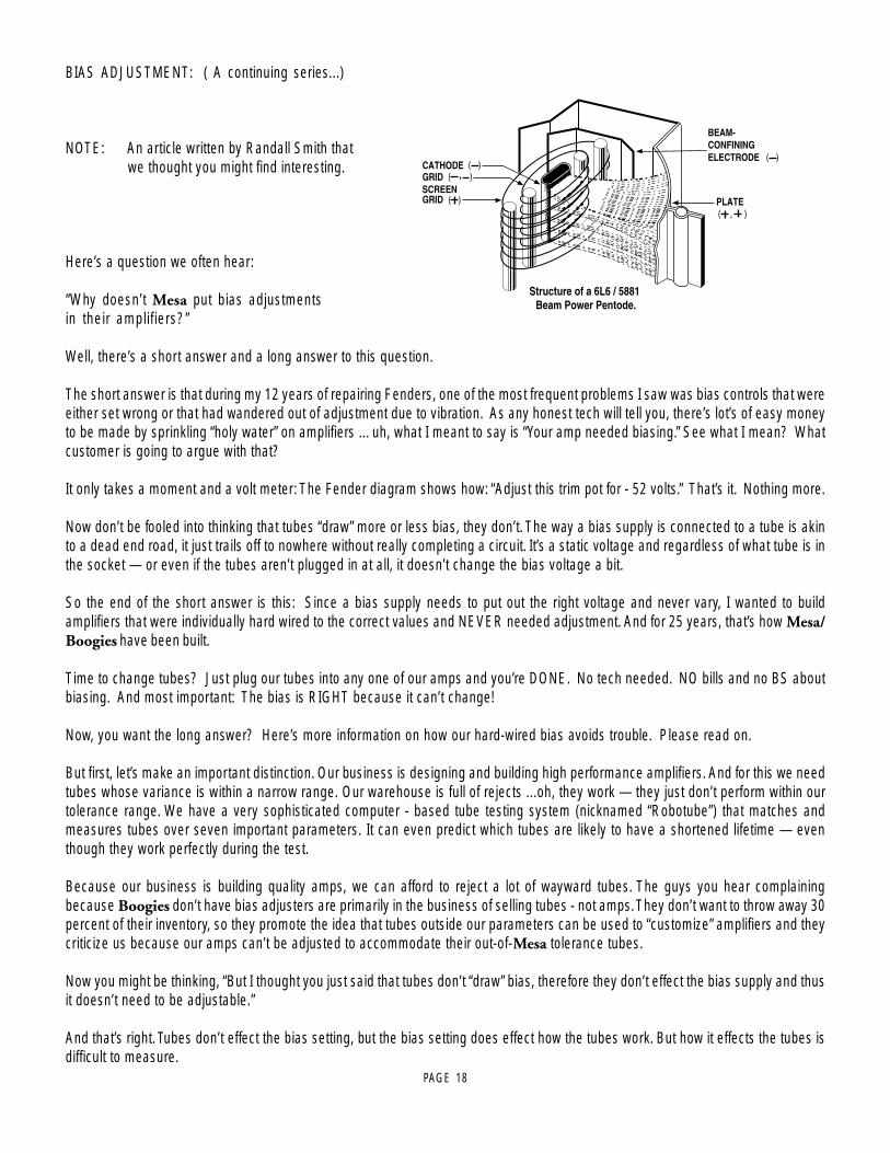
BIAS ADJUSTMENT: ( A continuing series...)
NOTE: An article written by Randall Smith that we thought you might find interesting.
Here’s a question we often hear:
“Why doesn’t Mesa put bias adjustmentsin their amplifiers?”
Well, there’s a short answer and a long answer to this question.
The short answer is that during my 12 years of repairing Fenders, one of the most frequent problems I saw was bias controls that wereeither set wrong or that had wandered out of adjustment due to vibration. As any honest tech will tell you, there’s lot’s of easy moneyto be made by sprinkling “holy water” on amplifiers ... uh, what I meant to say is “Your amp needed biasing.” See what I mean? Whatcustomer is going to argue with that?
It only takes a moment and a volt meter: The Fender diagram shows how: “Adjust this trim pot for - 52 volts.” That’s it. Nothing more.
Now don’t be fooled into thinking that tubes “draw” more or less bias, they don’t. The way a bias supply is connected to a tube is akinto a dead end road, it just trails off to nowhere without really completing a circuit. It’s a static voltage and regardless of what tube is inthe socket — or even if the tubes aren’t plugged in at all, it doesn’t change the bias voltage a bit.
So the end of the short answer is this: Since a bias supply needs to put out the right voltage and never vary, I wanted to buildamplifiers that were individually hard wired to the correct values and NEVER needed adjustment. And for 25 years, that’s how Mesa/Boogies have been built.
Time to change tubes? Just plug our tubes into any one of our amps and you’re DONE. No tech needed. NO bills and no BS aboutbiasing. And most important: The bias is RIGHT because it can’t change!
Now, you want the long answer? Here’s more information on how our hard-wired bias avoids trouble. Please read on.
But first, let’s make an important distinction. Our business is designing and building high performance amplifiers. And for this we needtubes whose variance is within a narrow range. Our warehouse is full of rejects ...oh, they work — they just don’t perform within ourtolerance range. We have a very sophisticated computer - based tube testing system (nicknamed “Robotube”) that matches andmeasures tubes over seven important parameters. It can even predict which tubes are likely to have a shortened lifetime — eventhough they work perfectly during the test.
Because our business is building quality amps, we can afford to reject a lot of wayward tubes. The guys you hear complainingbecause Boogies don’t have bias adjusters are primarily in the business of selling tubes - not amps. They don’t want to throw away 30percent of their inventory, so they promote the idea that tubes outside our parameters can be used to “customize” amplifiers and theycriticize us because our amps can’t be adjusted to accommodate their out-of-Mesa tolerance tubes.
Now you might be thinking, “But I thought you just said that tubes don’t “draw” bias, therefore they don’t effect the bias supply and thusit doesn’t need to be adjustable.”
And that’s right. Tubes don’t effect the bias setting, but the bias setting does effect how the tubes work. But how it effects the tubes isdifficult to measure.
..
.
.
.
...........
....
...
....
.......
..........
( )
( ) ( ) ,
( , )
( )
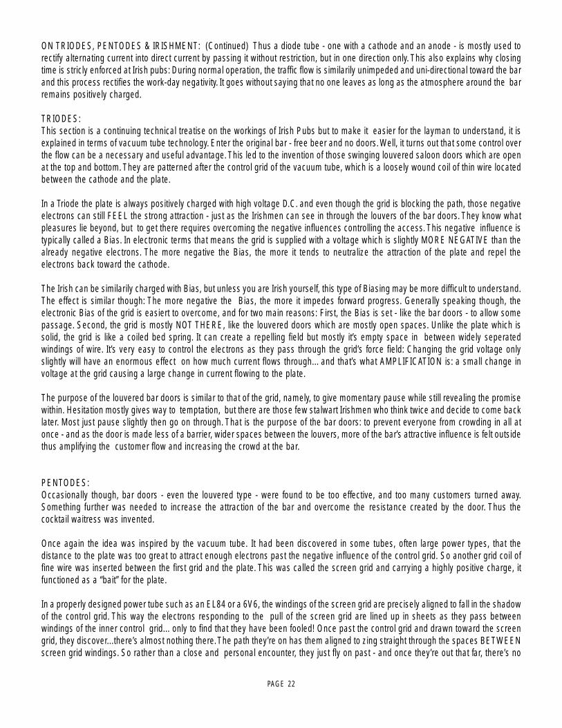
Structure of a 6L6 / 5881 Beam Power Pentode.
PLATE
BEAM-CONFININGELECTRODE
SCREENGRID
GRIDCATHODE
PAGE 19
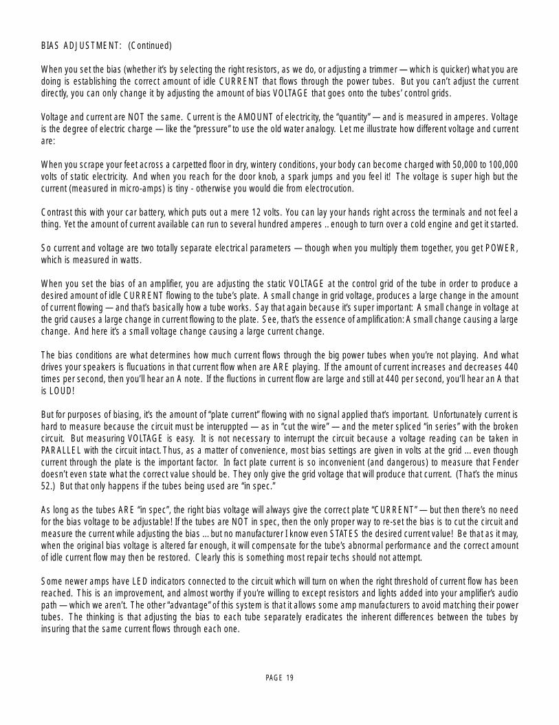
BIAS ADJUSTMENT: (Continued)
When you set the bias (whether it’s by selecting the right resistors, as we do, or adjusting a trimmer — which is quicker) what you aredoing is establishing the correct amount of idle CURRENT that flows through the power tubes. But you can’t adjust the currentdirectly, you can only change it by adjusting the amount of bias VOLTAGE that goes onto the tubes’ control grids.
Voltage and current are NOT the same. Current is the AMOUNT of electricity, the “quantity” — and is measured in amperes. Voltageis the degree of electric charge — like the “pressure” to use the old water analogy. Let me illustrate how different voltage and currentare:
When you scrape your feet across a carpetted floor in dry, wintery conditions, your body can become charged with 50,000 to 100,000volts of static electricity. And when you reach for the door knob, a spark jumps and you feel it! The voltage is super high but thecurrent (measured in micro-amps) is tiny - otherwise you would die from electrocution.
Contrast this with your car battery, which puts out a mere 12 volts. You can lay your hands right across the terminals and not feel athing. Yet the amount of current available can run to several hundred amperes .. enough to turn over a cold engine and get it started.
So current and voltage are two totally separate electrical parameters — though when you multiply them together, you get POWER,which is measured in watts.
When you set the bias of an amplifier, you are adjusting the static VOLTAGE at the control grid of the tube in order to produce adesired amount of idle CURRENT flowing to the tube’s plate. A small change in grid voltage, produces a large change in the amountof current flowing — and that’s basically how a tube works. Say that again because it’s super important: A small change in voltage atthe grid causes a large change in current flowing to the plate. See, that’s the essence of amplification: A small change causing a largechange. And here it’s a small voltage change causing a large current change.
The bias conditions are what determines how much current flows through the big power tubes when you’re not playing. And whatdrives your speakers is flucuations in that current flow when are ARE playing. If the amount of current increases and decreases 440times per second, then you’ll hear an A note. If the fluctions in current flow are large and still at 440 per second, you’ll hear an A thatis LOUD!
But for purposes of biasing, it’s the amount of “plate current” flowing with no signal applied that’s important. Unfortunately current ishard to measure because the circuit must be interuppted — as in “cut the wire” — and the meter spliced “in series” with the brokencircuit. But measuring VOLTAGE is easy. It is not necessary to interrupt the circuit because a voltage reading can be taken inPARALLEL with the circuit intact. Thus, as a matter of convenience, most bias settings are given in volts at the grid ... even thoughcurrent through the plate is the important factor. In fact plate current is so inconvenient (and dangerous) to measure that Fenderdoesn’t even state what the correct value should be. They only give the grid voltage that will produce that current. (That’s the minus52.) But that only happens if the tubes being used are “in spec.”
As long as the tubes ARE “in spec”, the right bias voltage will always give the correct plate “CURRENT” — but then there’s no needfor the bias voltage to be adjustable! If the tubes are NOT in spec, then the only proper way to re-set the bias is to cut the circuit andmeasure the current while adjusting the bias ... but no manufacturer I know even STATES the desired current value! Be that as it may,when the original bias voltage is altered far enough, it will compensate for the tube’s abnormal performance and the correct amountof idle current flow may then be restored. Clearly this is something most repair techs should not attempt.
Some newer amps have LED indicators connected to the circuit which will turn on when the right threshold of current flow has beenreached. This is an improvement, and almost worthy if you’re willing to except resistors and lights added into your amplifier’s audiopath — which we aren’t. The other “advantage” of this system is that it allows some amp manufacturers to avoid matching their powertubes. The thinking is that adjusting the bias to each tube separately eradicates the inherent differences between the tubes byinsuring that the same current flows through each one.

PAGE 20
BIAS ADJUSTMENT: (Continued)
Again, this has some merit .. but it’s still not as good as using tubes that are matched in the first place because compensating for themis-match causes the push-pull circuit itself to become unbalanced. Two wrongs don’t really make a right.
Some of the other recommended biasing, “methods” — such as -”.. tubes running red hot, increase the bias .. sounds harsh and runstoo cool, turn it down ...” are guesswork at best. Luckily, one of the great things about tube amps is that they can usually stand someabuse without causing any real harm ... at least not immediately.
But don’t these alterations imply that you are second-guessing the amp designer and that there’s a better set of operating conditionsthat the designer missed but the tube sellers have discovered?
Now some players may like the sound of their amp altered by tubes with extreme characteristics and with the bias set to helpcompensate. But often it is the mere novelty of change that they’re really responding to and when the amp goes back to the properoriginal way, we’ve seen them be far happier still!
Because every part in every one of our designs has been meticulously evaluated, compared and stressed over — no matter howseemingly insignificant it might be. And with every design we look for a “sweet spot” where all the parameters — including the bias —come together to give the best sonic performance, consistently and reliably. Every part and voltage is important — yet no onecomplains that these other parameters aren’t available for tinkering.
Consider our patented Simul-Class circuitry where there are two different bias voltages used for separate pairs of power tubes ... andchanging one voltage also changes the other. Great care goes into getting this just right and we think we’d be asking for trouble tohave it adjustable for the world to play with ... unless you like paying to have your amp messed up. Sorry, I meant to say, “Uh, ... youramp needed biasing.”
If that doesn’t appeal to you, then merely plug a matched set of Mesa tubes into one of our amps and you’re ready for tone. Guaran-teed. You’d be amazed at the number of service calls we field every day that lead to a diagnosis of out-of-tolerance, non-spec tubeproblems. To think these would be prevented by including a bias adjustment is something of an insult to you and us. If you put thewrong size tires on your car, do you think changing the pressure will make them right?
Please, don’t think this is a blanket indictment of the other guys selling tubes — it isn’t. And their tubes aren’t all bad either. It justdoesn’t make sense to pay more of your hard earned cash for tubes that were probably made in the same Russian or Chinese factoryand which have the possibility of being outside the performance window we select for your amp. And it pains us to hear the hype andmystique built up around biasing when twenty-five years of evidence affirms our decision to make bias circuits that “never needadjustment”. How much money and trouble that has saved Mesa/Boogie players you couldn’t estimate.
Our rigorously tested and hand selected tubes are available at your nearest Mesa/Boogie Pro Center or from us directly. Nobodyoffers better price, quality or warranty than we do ... so why swerve?
Next time we’ll talk about our part in developing the great Sylvania STR 415 type 6L6 and how we’re on the verge of seeing somethingfairly close reappear on the market. Remember, we still have some of these super rugged mondo-bottles available for older amps —Boogies only please! Until then, Relax, Breathe and Nourish your soul!
Cheers!Mesa/Boogie Ltd.
Randall SmithDesigner and President

PAGE 21
ON TRIODES, PENTODES & IRISHMENN
With apologies to Friends and Relatives from the Emerald Isle - who will make their appearance soon enough - the humor whichfollows is dedicated to the memories of Spec McAuliff and Fae (Rafael) McNally, two of the True Greats.
As their numerical references suggest, the terms Diode, Triode and Pentode indicate the number of elements within the vacuum tubei.e. two, three or five. All tubes also require a filament or heater which is not included in the count. Its purpose is to excite electronsfrom the cathode coating by raising the temperature such that they are able to boil out of the electron-rich coating material and forma cloud of free electrons in the vacuum space surrounding the cathode.
Although the term filament and heater are often used interchangeably, there are specific differences: A filament is a directly heatedcathode where cathode coating is applied directly to the heating element. Examples are 5U4 twin diode rectifier and 300B triodeamplifier tubes. A heater, on the other hand, is a heating element which is separate from the cathode and is usually inserted within thetubular cathode sleeve. Examples are 12AX7 twin triode amplifier and 6V6 or EL84 beam power pentode tubes. In all cases thisfundamental aspect of each tube’s construction is clearly visible, especially when the heating element is glowing red hot.
The cathode, then, would be considered the first numbered element because it is the source of the electrons. The word itself is fromthe Greek literally meaning completely down, which implies a sense of central origin - like the center of the earth where Tone begins.It might be said that an ecstatic audiophile experiences a positive catharsis, his soul being purified when his system transports him toAudio Nirvana. The only trouble with taking this positive imagery too far is that the cathode is, unfortunately, negative... at leastelectrically speaking. However this is easily remembered since virtually all musicians and audiophiles have also experienced themore common negative catharsis when they emerge from the emotional rebirth kicking and screaming in rage and frustration.
Once heated, the intrinsically negative electrons are energetic little fellows of almost no mass. Thus they may be accelerated almostinstantaneously and will travel through a vacuum a nearly the speed of light. Being of like, negative charge, they tend to repel oneanother and thus within the electron cloud surrounding the cathode, there is much jostling and elbowing as each one tries to maintainhis distance from all the others... unless there is a strong and universal attraction from an outside influence.
Visualize, if you will, a group of sub-atomic Irishmen milling about and in a repellent, negative state of mind. All are scowling and nonewants to have anything to do with the other. Now introduce a strong attraction say, a public bar, and you can easily picture an orderly,if rapid movement of the lot in a single direction. This is what happens when a positively charged element called the anode or plate isintroduced into the vacuum.
The plate is the large metal element most prominently visible through the glass of an electron tube. It is the outermost element of atube’s structure and it surrounds all the others. The cathode is at the center radiating electrons outwards. As higher and higherpositive voltage is applied to the plate, the attraction for the electrons surrounding the cathode is increased and with nothing standingin the way, full uninhibited flow to the plate occurs... sort of like removing the doors and offering free drinks to the crowd of surlyIrishmen milling around outside. As electrons flow to the plate, the space charge will continually be replenished by further ‘boiling’ ofthe hot, electron-rich cathode as you can easily imagine other Irishmen impatiently taking up the places of those who’ve gone inside- until the entire village is deserted.
Now, where do they come from and how do they emerge? Well, a grand and elegant lady once showed me how to revive flatchampagne: She dropped a raisin into the glass. There was a dramatic and immediate increase in effervescence with the introductionof a cathoding surface. Thousands of tiny bubbles suddenly appeared - and continued to flow from the raisin. Of course the bubbleswere made up of gas dissolved in the beverage, but the analogy makes it easy to visualize the loosely bound electrons dissolved inthe rich cathode coating as they effervesce from its heated surface.
But back to the electron flow. If the electrons are strongly attracted to a positively charged plate, then it follows that they are stronglyrepelled by a negatively charged plate and they are. Thus, if an alternating current - such as comes from a transformer - is applied tothe plate, electrons will flow only during the times when the plate is positively charged. During periods of negative plate charge,electron flow is stopped and the space charge of electrons remains compressed in the area around the cathode.
PAGE 22
ON TRIODES, PENTODES & IRISHMENT: (Continued) Thus a diode tube - one with a cathode and an anode - is mostly used torectify alternating current into direct current by passing it without restriction, but in one direction only. This also explains why closingtime is stricly enforced at Irish pubs: During normal operation, the traffic flow is similarily unimpeded and uni-directional toward the barand this process rectifies the work-day negativity. It goes without saying that no one leaves as long as the atmosphere around the barremains positively charged.
TRIODES:This section is a continuing technical treatise on the workings of Irish Pubs but to make it easier for the layman to understand, it isexplained in terms of vacuum tube technology. Enter the original bar - free beer and no doors. Well, it turns out that some control overthe flow can be a necessary and useful advantage. This led to the invention of those swinging louvered saloon doors which are openat the top and bottom. They are patterned after the control grid of the vacuum tube, which is a loosely wound coil of thin wire locatedbetween the cathode and the plate.
In a Triode the plate is always positively charged with high voltage D.C. and even though the grid is blocking the path, those negativeelectrons can still FEEL the strong attraction - just as the Irishmen can see in through the louvers of the bar doors. They know whatpleasures lie beyond, but to get there requires overcoming the negative influences controlling the access. This negative influence istypically called a Bias. In electronic terms that means the grid is supplied with a voltage which is slightly MORE NEGATIVE than thealready negative electrons. The more negative the Bias, the more it tends to neutralize the attraction of the plate and repel theelectrons back toward the cathode.
The Irish can be similarily charged with Bias, but unless you are Irish yourself, this type of Biasing may be more difficult to understand.The effect is similar though: The more negative the Bias, the more it impedes forward progress. Generally speaking though, theelectronic Bias of the grid is easiert to overcome, and for two main reasons: First, the Bias is set - like the bar doors - to allow somepassage. Second, the grid is mostly NOT THERE, like the louvered doors which are mostly open spaces. Unlike the plate which issolid, the grid is like a coiled bed spring. It can create a repelling field but mostly it’s empty space in between widely seperatedwindings of wire. It’s very easy to control the electrons as they pass through the grid’s force field: Changing the grid voltage onlyslightly will have an enormous effect on how much current flows through... and that’s what AMPLIFICATION is: a small change involtage at the grid causing a large change in current flowing to the plate.
The purpose of the louvered bar doors is similar to that of the grid, namely, to give momentary pause while still revealing the promisewithin. Hesitation mostly gives way to temptation, but there are those few stalwart Irishmen who think twice and decide to come backlater. Most just pause slightly then go on through. That is the purpose of the bar doors: to prevent everyone from crowding in all atonce - and as the door is made less of a barrier, wider spaces between the louvers, more of the bar’s attractive influence is felt outsidethus amplifying the customer flow and increasing the crowd at the bar.
PENTODES:Occasionally though, bar doors - even the louvered type - were found to be too effective, and too many customers turned away.Something further was needed to increase the attraction of the bar and overcome the resistance created by the door. Thus thecocktail waitress was invented.
Once again the idea was inspired by the vacuum tube. It had been discovered in some tubes, often large power types, that thedistance to the plate was too great to attract enough electrons past the negative influence of the control grid. So another grid coil offine wire was inserted between the first grid and the plate. This was called the screen grid and carrying a highly positive charge, itfunctioned as a “bait” for the plate.
In a properly designed power tube such as an EL84 or a 6V6, the windings of the screen grid are precisely aligned to fall in the shadowof the control grid. This way the electrons responding to the pull of the screen grid are lined up in sheets as they pass betweenwindings of the inner control grid... only to find that they have been fooled! Once past the control grid and drawn toward the screengrid, they discover...there’s almost nothing there. The path they’re on has them aligned to zing straight through the spaces BETWEENscreen grid windings. So rather than a close and personal encounter, they just fly on past - and once they’re out that far, there’s no

PAGE 23
PENTODES: (Continued) stopping them. The influence of the plate takes over and - being solid metal and of the highest positiveattraction - it is at this final destination that the electrons congregate.
Thus the proper cocktail waitress - visible through the louvers - is scantily clad so as to be all the more effective at reinforcing theattractive influence of her bar and by being located in between the door and the bar, she serves as bait to lure customers past thedoor’s negative influence. Once through the door however, it is the rare Irishman who actually comes in personal contact with thecocktail waitress as, for all intents and purposes, she - like the screen grid - turns out to be a vanishing illusion. Yet, having come thisfar, the solid influence of the bar itself now takes over and attracts the customers to congregate, having happily reached their destina-tion.
If you’re still following this and haven’t lost track of the count, you’ll know we’re still one element short of the five needed to make aPentode. This last part is a pair of beam-confining shields which being negatively charged, serve to direct the flow right toward theplate. This is much the way a short entrance hall to the bar prevents wandering accidentally into the Men’s room on the way.
Once at the bar though, the circuit is complete and the process of soul-nourishing works its ritual magic. Biases having beenovercome, illusory nightingales having vanished, the spirits truly soar and the once surly Irishmen now are filled with warmth, wit andkindred friendship, enjoying the music and glowing nicely with their heaters on.
With appreciative thanks to the inhabitants of the Land of the Leprechaun, we have now concluded our little diversion into themechanics of proper bar lay-out.
A feature article by Randall SmithDesigner / President
PAG
E 24
VOLUME 2 TREBLEMASTERVOLUME 1
POWER
BASS MIDDLE
1
2 60 RMS STANDBY TWEED
MARK I
ON100 RMS
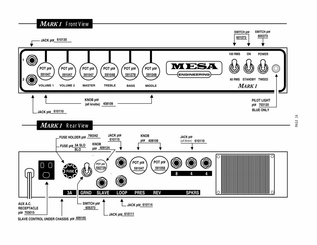
MARK I Front View
JACK pt#
KNOB pt# (all knobs)
JACK pt#
SWITCH pt#
PILOT LIGHT pt#
POT pt# POT pt# POT pt# POT pt#
591048
POT pt#
591278
POT pt#
591048
610130
610110
408109
591047 591047 591047
601073
SWITCH pt# 605373
703120BLUE ONLY
FUSE8 4 4
3A GRND SLAVE LOOP PRES REV SPKRS
FX LEVEL
INO
UT
MARK I Rear View
JACK pt#
POT pt# POT pt#
KNOBpt#
JACK pt#AUX A.C. RECEPTACLE pt# JACK pt#
POT pt#
KNOB pt#
FUSE HOLDER pt#
FUSE pt#
SWITCH pt#
JACK pt#(all three) 610110
610114
610111
605373
408109
591047 591058
610115
409124
592739
790342
3A SLO BLO
703015
SLAVE CONTROL UNDER CHASSIS pt# 409105

The Spirit of Art in Technology OOGIEBMESA
Thank you for trusting MESA/Boogie to be your amplifier company and we wish you many years of toneful enjoyment from this handbuilt all tube instrument.

The Spirit of Art in Technology
1317 Ross Street Petaluma, CA 94954USA
(707) 778-6565 FAX NO. (707) 765-1503