merry -go-round human powered genera tor
TRANSCRIPT

MERRY
HUMAN POWERED GENERA
Sarah Ashe and Salvador Navarro
ELECTRICAL ENGINEERI
California Polytechnic State University
MERRY-GO-ROUND
HUMAN POWERED GENERATOR
by
Sarah Ashe and Salvador Navarro
Senior Project
ELECTRICAL ENGINEERING DEPARTMENT
California Polytechnic State University
San Luis Obispo
2013 - 2014
TOR
NG DEPARTMENT

2 | P a g e
Table of Contents List of Tables and Figures ........................................................................................................... 3
Tables....................................................................................................................................... 3
Figures ..................................................................................................................................... 3
Abstract ....................................................................................................................................... 5
1) Introduction .......................................................................................................................... 6
2) Background .......................................................................................................................... 7
3) Requirements and Specifications ......................................................................................... 8
4) Design ................................................................................................................................ 10
Functional Decomposition ..................................................................................................... 10
Construction........................................................................................................................... 13
5) Hardware/Test Results ....................................................................................................... 17
Hardware ............................................................................................................................... 17
Test Results............................................................................................................................ 20
6) Conclusion and Recommendations .................................................................................... 25
Appendix A ............................................................................................................................... 26
SENIOR PROJECT ANALYSIS .......................................................................................... 26
1. Summary of Functional Requirements ........................................................................... 26
2. Primary Constraints ........................................................................................................ 26
3. Economic ........................................................................................................................ 26
4. If manufactured on a commercial basis: ........................................................................ 29
5. Environmental ................................................................................................................ 29
6. Manufacturability ........................................................................................................... 29
7. Sustainability .................................................................................................................. 29
8. Ethical............................................................................................................................. 30
9. Health and Safety ........................................................................................................... 30
10. Social and Political ..................................................................................................... 30
11. Development ............................................................................................................... 30
3 | P a g e
List of Tables and Figures
Tables
Table 3-1: Merry-Go-Round Requirements and Specifications ..................................................... 8
Table 4-1: Merry-Go-Round Generator Level 0 ........................................................................... 11
Table 4-2: AC Dynamo Generator Level 1 ................................................................................... 12
Table 4-3: AC-DC Rectifier Level 1 ............................................................................................ 12
Table 4-4 Boost Converter Level 1 ............................................................................................... 12
Table 4-5: Boost Converter Level 1 .............................................................................................. 13
Table A-1: Merry-Go-Round Cost, Time and Labor Estimates in EE460 ................................... 27
Table A-2: Bill of Materials Cost per Component........................................................................ 28
Figures
Figure 4-1: DC House System ...................................................................................................... 10
Figure 4-2: Level 0 Block Diagram of Merry-Go-Round ............................................................ 11
Figure 4-3: Level 1 Block Diagram of Merry-Go-Round ............................................................ 11
Figure 4-4: Base structure of the merry-go-round ........................................................................ 13
Figure 4-5: Center piece that holds the central shaft in place ....................................................... 14
Figure 4-6: The bearing mounted in the center of the merry-go-round ........................................ 14
Figure 4-7: Underneath the rotating platform where the cross beams are used for support ......... 15
Figure 4-8: Spacers mounted underneath the top base ................................................................. 15
Figure 4-9: Handrails being mounted to the rotating platform (top base) .................................... 16
Figure 4-10: Completed construction of the mechanical structure of the merry-go-round .......... 16
Figure 5-1: The complete system of the merry-go-round ............................................................. 17
Figure 5-2: AC dynamo generator ................................................................................................ 17
Figure 5-3: AC/DC rectifier .......................................................................................................... 18
Figure 5-4: DC/DC boost converter .............................................................................................. 18
Figure 5-5: 12V 8Ah rechargeable liquid sealed battery .............................................................. 19
Figure 5-6: DC/DC buck converter............................................................................................... 19
Figure 5-7: Standard USB Female connector ............................................................................... 20
Figure 5-8: The complete connection of the circuit ...................................................................... 20
Figure 5-9: Voltage waveform of the generators when the merry-go-round is starting to rotate at
low speed. ..................................................................................................................................... 21
Figure 5-10: Voltage waveform of the generators when the merry-go-round is rotating at a
constant high speed. ...................................................................................................................... 21
Figure 5-11: Voltage waveform of the generators when the merry-go-round is rotating at a
constant high speed. The time division is set to 1s/div. ................................................................ 22
Figure 5-12: Voltage waveform of the rectifier. The time division is set to 1s/div. ..................... 22
Figure 5-13: Voltage waveform of the rectifier. The time division is set to 100ms/div. .............. 23
Figure 5-14: Voltage waveform of the boost converter. ............................................................... 23

4 | P a g e
Figure 5-15: The current reading as the digital multi-meter is connected in series from the boost
converter to the battery. ................................................................................................................ 24
Figure 5-16: An iPhone being charged ......................................................................................... 24
Figure A-1: EE 460 Gantt Chart for the Human Powered Merry-Go-Round Generator.............. 27

5 | P a g e
Abstract
How do you bring electricity to families who have limited resources in a developing country? The DC House project, advised by Dr. Taufik, provides a way for kids to have fun, exercise and generate power for their homes – play-park human powered generators. This project intends to create a more efficient and cost effective way for playground equipment to be implemented for power generation. The redesigned and reconstructed merry-go-round human powered generator converts mechanical energy into electrical energy to power the DC house. This was a fully functioning generator that needed a better voltage gain, as well as, a more effective design for the physical merry-go-round. The merry-go-round utilizes renewable human energy, more specifically children’s energy, to create a sustainable source for the DC house. The generator supplies DC power to a battery where the DC house pulls its power from.
6 | P a g e
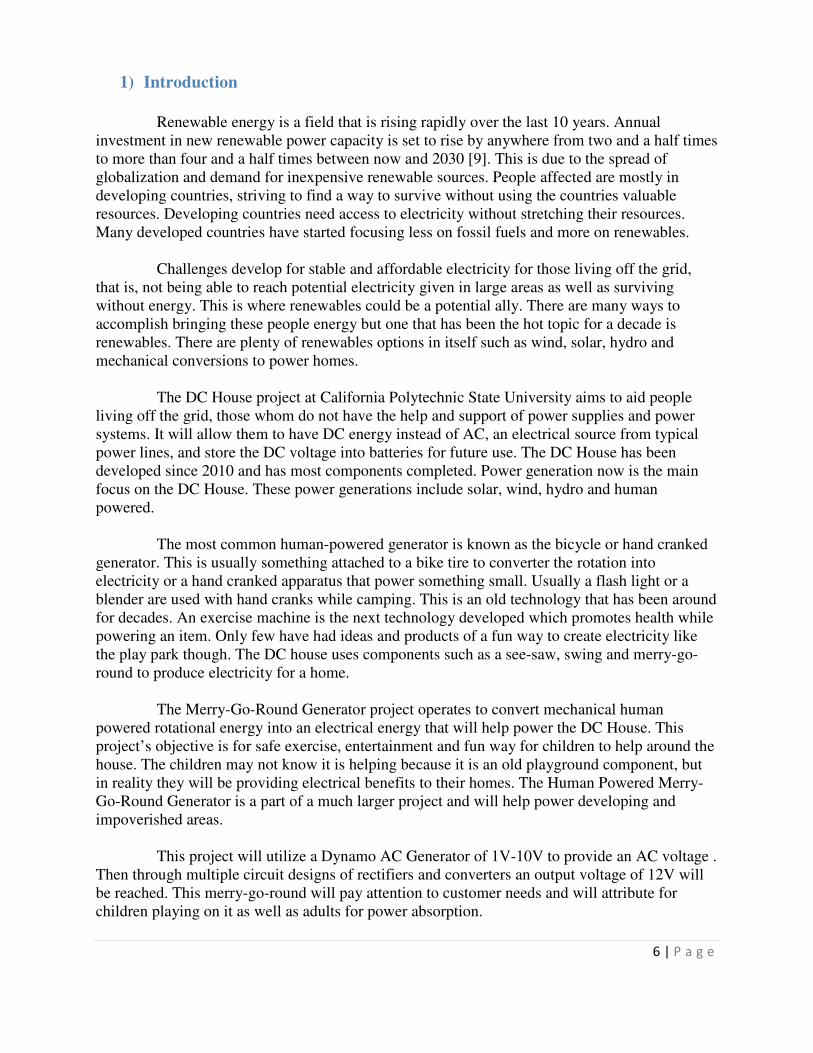
1) Introduction
Renewable energy is a field that is rising rapidly over the last 10 years. Annual investment in new renewable power capacity is set to rise by anywhere from two and a half times to more than four and a half times between now and 2030 [9]. This is due to the spread of globalization and demand for inexpensive renewable sources. People affected are mostly in developing countries, striving to find a way to survive without using the countries valuable resources. Developing countries need access to electricity without stretching their resources. Many developed countries have started focusing less on fossil fuels and more on renewables. Challenges develop for stable and affordable electricity for those living off the grid, that is, not being able to reach potential electricity given in large areas as well as surviving without energy. This is where renewables could be a potential ally. There are many ways to accomplish bringing these people energy but one that has been the hot topic for a decade is renewables. There are plenty of renewables options in itself such as wind, solar, hydro and mechanical conversions to power homes. The DC House project at California Polytechnic State University aims to aid people living off the grid, those whom do not have the help and support of power supplies and power systems. It will allow them to have DC energy instead of AC, an electrical source from typical power lines, and store the DC voltage into batteries for future use. The DC House has been developed since 2010 and has most components completed. Power generation now is the main focus on the DC House. These power generations include solar, wind, hydro and human powered. The most common human-powered generator is known as the bicycle or hand cranked generator. This is usually something attached to a bike tire to converter the rotation into electricity or a hand cranked apparatus that power something small. Usually a flash light or a blender are used with hand cranks while camping. This is an old technology that has been around for decades. An exercise machine is the next technology developed which promotes health while powering an item. Only few have had ideas and products of a fun way to create electricity like the play park though. The DC house uses components such as a see-saw, swing and merry-go-round to produce electricity for a home. The Merry-Go-Round Generator project operates to convert mechanical human powered rotational energy into an electrical energy that will help power the DC House. This project’s objective is for safe exercise, entertainment and fun way for children to help around the house. The children may not know it is helping because it is an old playground component, but in reality they will be providing electrical benefits to their homes. The Human Powered Merry-Go-Round Generator is a part of a much larger project and will help power developing and impoverished areas. This project will utilize a Dynamo AC Generator of 1V-10V to provide an AC voltage . Then through multiple circuit designs of rectifiers and converters an output voltage of 12V will be reached. This merry-go-round will pay attention to customer needs and will attribute for children playing on it as well as adults for power absorption.

7 | P a g e
2) Background
1.2 billion, nearly 17% of the world’s population, has no access to electrical power due to
no power generated systems or great distance from the power grid [19]. The United Nations
(UN) has issued the Sustainable Energy for All initiative which states that everyone in the world
will have access to electricity by 2030 [20]. In order to reach this goal, an estimated new capital
investment of $35-$40 billion a year is required.
One project that could contribute to helping lower the cost of capital for the UN is The
DC House Project [8]. This is a small scale electrical system that uses renewables strictly
independent of the grid. The DC House could also add to the UNs goal of doubling the world’s
renewables from 15% to 33% in the span of 2010-2035 [21]. This project was started by
California Polytechnic State University [8]. The DC House was created from the idea of using
advances in power electronics to help improve the world. The goal is to start expanding this
project into third-world countries by 2015.
The DC House’s drive is to provide DC power to those living in rural areas for whom
cannot access modern electricity. The DC house uses all renewable energy from renewable
resources to human powered generators. As power electronics develop the use for large
generators and distribution lines diminishes. This will reduce the cost while improving the
system’s efficiency. The Merry-Go-Round Human Powered Generator’s main priority, is to
provide a source of renewable energy to a household while attributing a way for children to
exercise and have fun. The merry-go-round will provide energy to the human powered aspect of
the DC House. This project was started in 2012 [15] where each component has been created and
altered by each group. The merry-go-round started with a simple design which was made out of
wood with casters to rotate and a magnetic field design where magnets rotated over coils to
produce a voltage. This design however was hard to rotate and did not produce enough volts to
charge a battery.
This project will focus mostly on redesigning the physical aspect of the merry-go-round
by making sure it is easy to spin. A child the age of at least 5 should be able to spin the merry-
go-round without a struggle. The old design took two grown men to get it to spin a little bit.
Also, the electronics will be changed to a couple dynamo generators instead of magnetics to
produce a small voltage which will then be rectified and boosted. A 12V rechargeable battery
will be used in this project which the other design tried to accomplish and failed.

8 | P a g e
3) Requirements and Specifications
The requirements and specifications listed in Table 2-1 were created using customer
needs. The specifications were justified viewing the previous model [15] [16] and adding percent
error. This merry-go-round needs to be mobile in case it will be shipped to other countries. Also,
if it will be implemented for poverty areas it will need to be low cost [9].
The generator should output 1V-4V AC which will be rectified and stepped up to 12V [10]. The
bulk of these requirements will be due to safety issues according to the IEEE Code of Ethics.
Table 3-1: Merry-Go-Round Requirements and Specifications
The requirements and specifications table format derives from [17], Chapter 3.
Marketing
Requirements
Engineering
Specifications Justification
1-5 Sustain an output power greater than 40 watts. Based upon previous system requirements [15].
1 Continuously rotatable in both directions. There should be no polarity issues therefore
allowing a bi-directional flow.
2,5 The final design will output 12V DC and
charge a car battery.
This will guarantee the household has a backup
battery for future use.
1-5 Mass production cost less than $250. Based upon previous system designs. Will be
built in developing countries where it needs to
be cost effective [15].
1,5,6 Easy to rotate for children ages 5 and up. Previous design was difficult to rotate.
Therefore not producing enough voltage output.
Also, children should be able to spin it by
themselves [15].
1-7 The base diameter 6ft and handle up to
800lbs.
The base will be long enough to hide the
generator and handle multiple kids.
1-7 Generator will output a 1V-4V AC voltage. This is a requirement from the linear
technologies boost converter module.
5 Any wiring used will be concealed yet
accessible.
This will prevent safety hazards while children
are playing on the merry-go-round.
Marketing Requirements
1. Rotate freely/bi-directionally.
2. Charge a 12V battery.
3. Mobile for transportation.
4. Low cost.
5. Structurally sound for desired rotation and weight.
6. Recyclable materials.
7. Able to handle all different weather conditions.

9 | P a g e
The Merry-Go-Round shall be stable and safe for all ages. It must be able to be rotated by a small child because the last design was hard to rotate by two men. The production cost shall not exceed $250 due to this project being placed in third world countries. It shall be able to store energy into a 12V rechargeable battery and then be able to pull power from the battery to power a USB port or any load in the DC house. The energy will be converted from AC to DC voltage and boosted to charge the battery. This will be done by using four dynamo generators in parallel which will produce an AC voltage in the range of 1V-4V. This AC voltage will then be pushed through a full bridge rectifier which will change the voltage from AC to DC. The DC voltage will then be put through a boost converter which will step up the DC voltage to the desired 12-14V to charge the battery. Also a buck converter will be used off the battery to power a USB port at 5V, where one can view that the battery is actually being charged and charge a small electronic such as a phone.

10 | P a g e
4) Design
Functional Decomposition
The merry-go-round will be issued in the human-powered portion of the DC House system,
shown in Figure 4-1. This will be intertwined with the other renewable sources connected to the
battery array and DC-DC converter connected to the home.
Figure 4-1: DC House System
A figure similar to Figure 4-1 can be found on the DC House Website showing the DC
House design [7].
A. LEVEL 0 BLOCK DIAGRAM
Humans apply mechanical energy by rotating the merry-go-round generator. The Level 0
block diagram in Figure 4-2 shows that the generator converts AC voltage to 12V DC. This 12V then is powered to a battery to charge.

11 | P a g e
Figure 4-2: Level 0 Block Diagram of Merry-Go-Round
Table 4-1 describes all functionalities of the level 0 block diagram including details on
the inputs and outputs.
Table 4-1: Merry-Go-Round Generator Level 0
Module Merry-Go-Round Generator
Inputs The human mechanical energy is from the rotation of the merry-go-round.
Outputs The 12V DC output is to charge the battery.
Functionality A rectified and regulated power will be produced by rotating the merry-go-
round. Then, the power will be connected to a DC battery.
B. LEVEL 1 BLOCK DIAGRAM
Figure 4-3 shows a deeper level then Figure 4-2. This block diagram shows the AC dynamo
generator, rectifier and boost converter used to output the 12V to be stored in a rechargeable battery. Then, a buck converter is added to step down to the USB’s 5V capacity.
Figure 4-3: Level 1 Block Diagram of Merry-Go-Round
Table 4-2 describes all functionalities of the AC dynamo generator. As the Merry-Go-Round rotates it will spin a rotor causing the generator to produce unregulated voltage which is then rectified and fed into the boost converter to produce a 12V output. There will be four dynamos in parallel each rated with 6W.
Human
Mechanical
Energy
Dynamo
Generator
AC/DC
Rectifier Boost
Converter
12V
Rechargeable
Battery Buck
Converter 5V USB
Port

12 | P a g e
Table 4-2: AC Dynamo Generator Level 1
Module AC Dynamo Generator
Inputs The human mechanical energy is from the rotation of the merry-go-round.
Outputs AC voltage at 1V – 12V.
Functionality The generator will convert the mechanical energy from the rotation to an AC
electrical voltage.
Table 4-3 describes all functionalities of the AC-DC Rectifier module. The rectifier will have the input of the AC dynamo generators output at 1V – 12V AC. Then, the rectifier will convert the AC voltage to a DC voltage equivalent with some AC output voltage ripple. This AC ripple can be reduced by implementing a capacitor filter.
Table 4-3: AC-DC Rectifier Level 1
Module AC-DC Rectifier
Inputs AC voltage at 1V-12V.
Outputs DC voltage close to 1V – 10V with an AC ripple output.
Functionality The AC-DC rectifier converts AC voltage to DC voltage with a peak value that
is very similar.
Table 4-4 describes all functionalities of the Boost Converter module. The boost converter will take a small input voltage and step it up to the desired output voltage. There is however a small ac output voltage ripple. Linear Technologies makes boost converter module which can handle these specifications [10].
Table 4-4 Boost Converter Level 1
Module Boost Converter
Inputs DC voltage close to 1V – 10V with an AC ripple output.
Outputs The 12V DC output is to charge the battery.
Functionality The boost converter will step up the smaller DC voltage at 1V-10V to a 12V
DC output.

13 | P a g e
Table 4-5 describes all functionalities of the Buck Converter module. The buck converter will take an input voltage and step it down to the desired output voltage. This voltage will be used to power a USB port for testing purposes and demonstrations.
Table 4-5: Boost Converter Level 1
Module Buck Converter
Inputs DC voltage of 12V.
Outputs The 5V DC output to power a USB port.
Functionality The buck converter will step down the DC voltage at 12V to a 5V DC output.
Construction
The Merry-Go-Round consists of four parts, each of which is very vital to the mechanical structure. The first part is the base which holds the Merry-Go-Rounds weight and stabilizes the rotating piece. It also harnesses the central shaft for which the Merry-Go-Round is revolving around. The next part is a bearing and dynamo generator mounts which are attached to the base underneath the rotating piece. Then a spacer of three 1” plywood pieces are attached to the top piece giving the dynamos the proper distance to place their rotors on to the rotating platform. Furthermore, a platform with a 6’ diameter is stabilized with cross beams and placed on top of the base. Lastly, handrails made of 3/4” conduit are bent in place and attached to center rotating shaft.
Figure 4-4: Base structure of the merry-go-round

14 | P a g e
Figure 4-4 shows the structure of the bottom of the base that will hold the merry-go-round together. These were created with 2’x6” and 2’x4” wood beams. The diameter of the base totals 4’.
Figure 4-5: Center piece that holds the central shaft in place
Figure 4-5 illustrates the center piece that holds the central shaft in place. It is made of a 2-3/8” fence post covered with a PVC adapter to the 1-5/8” fence post that will rest inside. YARDGAURD 2-3/8” galvanized steel tension bands were used to secure the fence post to the base structure.
Figure 4-6: The bearing mounted in the center of the merry-go-round
Figure 4-6 displays the base completely constructed with the bearing attached in the center. The bearing is a 12” diameter with a 1000lb rating. Dynamo generators will be attached at the edge into one of the support beams.

15 | P a g e
Figure 4-7: Underneath the rotating platform where the cross beams are used for support
Figure 4-7 shows the rotating platform upside down illustrating the cross beams for support, as well as, the 3’ in diameter circle which will be placed on the dynamos rotors to generate power as it rotates.
Figure 4-8: Spacers mounted underneath the top base
Figure 4-8 illustrates the spacers added to the rotating platform to give the ample amount of room for the dynamos to fit under the rotating piece.

16 | P a g e
Figure 4-9: Handrails being mounted to the rotating platform (top base)
Figure 4-9 displays the 3/4” conduit being connected by two U-brackets to an 8” 2’x4” piece of wood mounted to the rotating platform with two 1” L-brackets and one 2” L-brackets. This adds extra support and strength to the handles.
Figure 4-10: Completed construction of the mechanical structure of the merry-go-round
Figure 4-10 shows the finished construction of the mechanical structure of the merry-go-round. It displays the center shaft made of 1-5/8” fence post connected to the conduit by a 1-5/8” U-bracket bolted to a Halex 3/4” steel conduit and pipe hanger.

17 | P a g e
5) Hardware/Test Results
Hardware
This section discusses the different hardware used and how they are connected in the
system. Figure 5-1 describes where each circuit are connected in the system. As the merry-go-
round is rotating, it will be spinning a rotor from the dynamo generator which produces AC
voltage. In order to store the energy in a rechargeable battery, the AC signal needs to be rectified
to a DC signal. An AC/DC rectifier is used to convert the signal from AC to DC. After the
rectifier, there is a boost converter circuit that helps step-up the voltage to a desired output
voltage. A 12V rechargeable battery is placed right after the boost converter to store the energy.
For testing purposes, a buck converter is used to step-down the voltage to a desired voltage. An
iPhone is connected to a USB port to show the charging capability of the system.
Figure 5-1: The complete system of the merry-go-round
Figure 5-2: AC dynamo generator
Figure 5-2 illustrates an AC dynamo generator. Four generators are used in the merry-go-
round and are connected in parallel. This would allow more current to flow through the circuit to
Human
Mechanical
Energy
Dynamo
Generator
AC/DC
Rectifier Boost
Converter
12V
Rechargeable
Battery Buck
Converter 5V USB
Port

18 | P a g e
help charge the battery faster. Each generator is rated at 12V and 6W. The cost for one dynamo
generator is roughly around $20. Five dynamos were ordered in a packaged which had a total
savings of $40.
Figure 5-3: AC/DC rectifier
A 1A bridge rectifier is used to convert the AC signal to DC signal as shown in Figure 5-
3. The cost for one rectifier is about $0.50. Converting the signal to DC allows the system to use
a DC/DC boost converter – a power electronic circuit as shown in Figure 5-4. Essentially, the
converter is a replacement for a transformer which takes up less space on the board and cost less
to manufacture. Also, to store the energy generated from the merry-go-round to a 12V
rechargeable battery, the voltage generated by the generator needs to be converted to a DC
signal. The input of the converter is rated 2.5V to 25V and the output is rated 5V to 25V. The
potentiometer is adjusted to the desired output voltage of 14V. In order to have a working circuit,
the generator needs to output a minimal voltage of 2.5V to step it up to 14V. The cost for one
converter is $0.75.
Figure 5-4: DC/DC boost converter

19 | P a g e
Figure 5-5: 12V 8Ah rechargeable liquid sealed battery
Figure 5-6 shows a 12V 8Ah rechargeable liquid sealed battery. An 8Ah is selected in
order to charge an iPad within 8 hours. The following equation is used to determine the
minimum rating of the battery.
�ℎ =������� �� ����� × ����������ℎ����
� ��������� �����=12� × 8ℎ
12�= 8�ℎ
An iPad is rated at 12W and it usually takes about 6-8 hours to fully charge when charged
from the wall outlet. Since the rechargeable battery is rated at 12V, the total Ah comes out to be
8Ah. The cost of the battery is $22.
Figure 5-6: DC/DC buck converter
Figure 5-5 illustrates another power electronic circuit, DC/DC buck converter. This
converter steps down the voltage to a desired value. The input of the converter is rated 4V to
35V and the output is rated 1.23V to 30V. The potentiometer is adjusted to the desired output
voltage of 5V. The cost of the converter is $0.75. The converter steps down the voltage to 5V
which an iPad can be connected and charged from a USB female connector as shown in Figure
5-7. The USB connector cost approximately $1. Figure 5-8 illustrates the complete connection of
the system.

Figure
Figure 5-
Test Results
During the testing phase, an Analog Discovery Design Kit was used to measure the
voltages. The Analog Discovery Design Kit is a
This allowed an easy access to monitor the voltage waveforms from a remote location. This
section will overview the different output voltage waveforms from the three circuitry: generators,
rectifier and boost converter.
Figure 5-7: Standard USB Female connector
-8: The complete connection of the circuit
During the testing phase, an Analog Discovery Design Kit was used to measure the
voltages. The Analog Discovery Design Kit is a powered USB with dual channel oscilloscope.
This allowed an easy access to monitor the voltage waveforms from a remote location. This
section will overview the different output voltage waveforms from the three circuitry: generators,
20 | P a g e
During the testing phase, an Analog Discovery Design Kit was used to measure the
powered USB with dual channel oscilloscope.
This allowed an easy access to monitor the voltage waveforms from a remote location. This
section will overview the different output voltage waveforms from the three circuitry: generators,
21 | P a g e
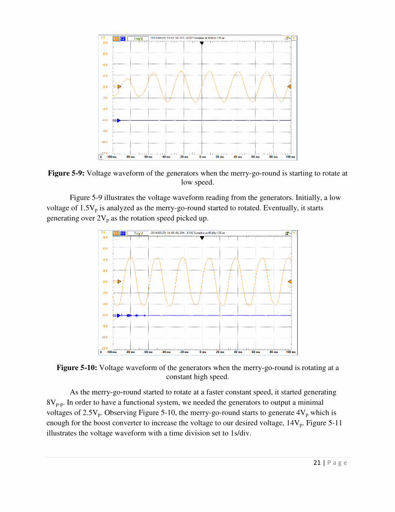
Figure 5-9: Voltage waveform of the generators when the merry-go-round is starting to rotate at low speed.
Figure 5-9 illustrates the voltage waveform reading from the generators. Initially, a low
voltage of 1.5Vp is analyzed as the merry-go-round started to rotated. Eventually, it starts
generating over 2Vp as the rotation speed picked up.
Figure 5-10: Voltage waveform of the generators when the merry-go-round is rotating at a constant high speed.
As the merry-go-round started to rotate at a faster constant speed, it started generating
8Vp-p. In order to have a functional system, we needed the generators to output a minimal
voltages of 2.5Vp. Observing Figure 5-10, the merry-go-round starts to generate 4Vp which is
enough for the boost converter to increase the voltage to our desired voltage, 14Vp. Figure 5-11
illustrates the voltage waveform with a time division set to 1s/div.

22 | P a g e
Figure 5-11: Voltage waveform of the generators when the merry-go-round is rotating at a constant high speed. The time division is set to 1s/div.
Figure 5-12: Voltage waveform of the rectifier. The time division is set to 1s/div.
After the generators, there is a rectifier connected which converts the AC signal to DC.
Figure 5-12 demonstrates the voltage waveform in DC voltage. Figure 5-13 illustrates the DC
voltage with a time division set to 100ms/div.

23 | P a g e
Figure 5-13: Voltage waveform of the rectifier. The time division is set to 100ms/div.
Figure 5-14: Voltage waveform of the boost converter.
After the rectifier there is a boost converter that is adjusted with a potentiometer to 14V. Analyzing Figure 5-14, one can see the output voltage is varying around our desired voltage. Figure 5-15 shows a digital multi-meter connected in series from the DC/DC boost converter to the 12V rechargeable battery. As analyzed in the photo, a recording of 25.9mA was recorded from the system. This illustrates the current flowing into the battery which demonstrates the charging functionality of the system.

24 | P a g e
Figure 5-15: The current reading as the digital multi-meter is connected in series from the boost converter to the battery.
Figure 5-16: An iPhone being charged
Lastly, to test if the circuit is working properly, an iPhone is connected to the USB
connector. As shown in Figure 5-16, it shows that the phone is currently being charged as
indicated by the picture shown on the screen of the phone.

25 | P a g e
6) Conclusion and Recommendations
This project’s main objective is to provide a fun and clean renewable energy for people living in a developing country or in a rural area where the grid does not reach. We re-created and re-designed a merry-go-round that converts mechanical energy from human production into electricity to charge a USB device. The old design used casters which caused high friction loss and made the merry-go-round hard to spin. Our design includes a new Lazy Susan bearing rated at 1000lbs which made the merry-go-round much easier to spin. The design was meant to be relatively simple for a cost efficient product. The merry-go-round itself can hold up to 900lbs (calculated from the rated bearing of 1000lbs minus the weight in material lying on the bearing) which is large enough for small children and a few adults. The merry-go-round will generate electricity under load and no-load conditions. The merry-go-round does generate up to 15V and will power the 12V rechargeable battery. The physical aspect of the merry-go-round however is not as stable as assumed for a few reasons.
Reusing material from the old merry-go-round proved efficient but may not last as long
as predicted. The material was stored in outside weather conditions and was not perfect for construction but recycling the old material for a demonstration product seemed ideal. Also, the base of the merry-go-round could be larger to accommodate better stability of the rotating piece. There could also be 4 casters added upside down and mounted to the base for more stability to keep the base the size it is. The casters would rotate with the top piece and add solid four areas further out on the merry-go-round diameter so it does not tip sideways. This project could also benefit from being multidisciplinary by involving a mechanical engineering student. The merry-go-round would profit from being designed in solid works and having someone who is good at welding design it out of metal. We used wood for the whole merry-go-round base and rotating apparatus because we only had tools served for wood material. Also, wood is cheaper than metal keeping our production cost down. Overall, the DC House is an ongoing project created by students and professors at California Polytechnic State University to help better the lives of others in developing countries. Our merry-go-round is a small portion of this project to help show the variety of renewable sources one can propose for a completely sustainable home. Creating a source that is able to provide enough electricity to power a small rechargeable 12V battery shows the concept behind a much greater energy source. Our hope is that another group will be able to create an energy storage and consumption source that can take energy from all the renewable resources and store it for use by the DC loads inside a DC House.

26 | P a g e
Appendix A
SENIOR PROJECT ANALYSIS
1. Summary of Functional Requirements
The merry-go-round human powered generator converts mechanical energy into electrical energy by the rotation of the merry-go-round. Humans/children can spin the physical aspect of the merry-go-round in a circular motion. This will turn the dynamo generators producing an electrical output charging a battery. The battery will be in an array for the DC house which can be stored for future energy absorption.
2. Primary Constraints
Figuring out the appropriate generator for the project that factors in characteristic rotational speed of the apparatus which provides a voltage output will be quite difficult. Also, factoring in if the merry-go-round needs to be mobile can cause mechanical design issues to the physical aspect. Balancing out specific weights on a model that breaks apart can cause balance, wear and tear issues and efficiency problems. This will cause consultations/teamwork from a mechanical engineer student. This in turn could increase the cost of the project due to labor and consultation prices. The merry-go-round is intended for use by multiple children creating vast amount data observations before production. Liability could also be an issue if America is shipping to a third world country.
3. Economic
This project is focused toward third world villages or impoverished areas. This project will provide an energy source for villages off the grid, which cannot not afford to deliver energy to power their homes. The production costs will take over producing at generation plants and delivering to remote areas for the duration of the products lifetime. This project is mostly on a charitable basis so for the donor there may be no profit. Possibly as a charity write off for taxes but the profit actually comes for the recipients. The recipients will have a renewable power source for a house that most likely never used to have power. This could be profitable for them by having a way to see at night instead of candle light where they smell smoke all night which could cause them medical problems. Also, the energy produced could provide a way to heat food and water which could kill bacteria. With proper maintenance the merry-go-round should last at least 10 years for each household. The project should cost less than $250. Maintenance should occur at least once every three years which could include paint costs and upgrades costing approximately $50 including labor cost for maintenance. To purchase the product the donor must use some sort of payment (i.e. credit, stock, bank notes, etc.), to the manufacturing company. There must also be a delivery fee to ship to the recipient and possibly assemble at their location. Financial capital then lies outside of this project. Human capital can be realized in a fun way to produce energy. The merry-go-round, generator, and voltage converter are realizations of the project that produce manufactured

27 | P a g e
capital. Each time the merry-go-round spins it creates energy that was never there as well as not using purchased energy from the grid.
GANTT CHART AND COST ESTIMATES:
Figure A-1: EE 460 Gantt Chart for the Human Powered Merry-Go-Round Generator
Table A-1: Merry-Go-Round Cost, Time and Labor Estimates in EE460
Material Cost to Purchase Time to Integrate into System (Days)
Optimistic Realistic Pessimistic Estimate Optimistic Realistic Pessimistic Estimate
Merry-Go-Round $100 $175 $300 $230 5 10 13 9
AC Generator $40 $50 $80 $60 7 9 11 9
AC-DC Converter $0.25 $0.50 $1.00 $0.60 3 7 12 7
Boost Converter $0.50 $0.75 $1.00 $0.75 2 4 7 4
Buck Converter $0.50 $0.75 $1.00 $0.75 1 1 3 2
12V Rechargeable Battery $15 $22 $30 $22 1 1 3 2
Misc. $20 $25 $50 $67 7 10 15 10
Total Cost and Time $176.25 $274 $463 $304 26 51 91 43
Actual Cost and Time $250 50

28 | P a g e
Table A-1 describes the different outcomes for the cost and time it will take to produce the merry-go-round. Each depends on optimistic, pessimistic and realistic costs. Each cost was estimated off actual products depending on the specifications needed. Making sure our project is cost efficient relies on having a distinct design before ordering. This could cost more time than money in the long run making the project have a constraint to finish construction. The Misc. items include labor, wiring, insulation and any other finishing costs.
Table A-2: Bill of Materials Cost per Component
Bill of Materials
Decription Quantity
Unit
Price
Total
Price
7/8in x 2ft x 2ft Plywood 3 $1.88 $5.64
7/8in x 4ft x 8ft Plywood 4 $9.55 $38.20
2in x 4in x 10ft Lumber 1 $4.25 $4.25
2in x 6in x 8ft Lumber 3 $4.98 $14.94
#8 1/2 in Flat Head Wood Screw 1lb. Pack 1 $6.47 $6.47
#8 1 in Flat Head Wood Screw 1lb. Pack 1 $6.95 $6.95
#8 1-1/2 in Flat Head Wood Screw (1lb. Pack) 1 $7.59 $7.59
#8 2 in Flat Head Wood Screw (1lb. Pack) 1 $7.98 $7.98
1-1/2 in L Bracket (4-Pack) 2 $2.67 $5.34
2 in L Bracket (2-Pack) 2 $3.47 $6.94
3/4in x 5ft Metal Conduit 4 $2.45 $9.80
1/2in Ridgid 2-Hole Conduit Straps (10-Pack) 1 $1.55 $1.55
3/4in Conduit Hanger with Nut and Bolt (5-Pack) 1 $1.55 $1.55
Grease 1 $3.56 $3.56
Dynamo Generator 12V 6W 4 $18.23 $72.92
Lazy Susan Bearing 1000lb Rating 1 $15.00 $15.00
3in Bolts Nuts and Washers (4 Pack) 6 $1.15 $6.90
1-1/2in Bolts, Nuts and Washers (4 Pack) 1 $1.15 $1.15
Plasti Dip Rubber Coating 1 $4.99 $4.99
1-5/8in x 8ft 16 Gauge Galvanized Steel Post 1 $15.98 $15.98
1-5/8in Chain Link Post Cap 1 $1.75 $1.75
1-5/8in Steel Tension Band 2 $0.78 $1.56
1-5/8in Brace Band 4 $1.31 $5.24
PVC 3/4in x 2 ft 2 $1.24 $2.48
PVC 3/4in Slip and Slip Coupling 2 $0.21 $0.42
1/2in x 6ft Plastic Conduit and End Tips 1 $8.79 $8.79
Junction Box 1 $17.29 $17.29
Redwood Waterproof Stain (1-Gal) 1 $22.56 $22.56
Total Cost
$297.79

29 | P a g e
4. If manufactured on a commercial basis:
This will be considered as a non-profit organization and will never be produced on a commercial basis.
5. Environmental
This project does not use conventional energy sources such as burning coal or nuclear power plants. This means there is not gaseous emissions except paint and lubricant evaporation which on a small scale will not harm the ozone. This project does take a good amount of space outdoors possibly removing vegetation and minerals. Although, this could be bypassed by good planning the merry-go-round could be placed in an area that has already been cleared due to previous natural weather. There also may be a need for chemicals such as weed killers to keep the electrical components under the merry-go-round away from any growing weeds. Also, animals may want to nest near or around the merry-go-round. This means the merry-go-round might need to be encaged or just watched for some animals. If any animals get up inside the merry-go-round while in motion they can be badly hurt. The material used in the production of the merry-go-round has a large impact once the merry-go-round does not work or will not be used again. Each of the materials can be broken down and recycled.
6. Manufacturability
The merry-go-round will not be designed and created completely from scratch; giving the project a chance for error in pre-manufactured parts. Also, the construction of the apparatus will be done by humans’ not precision machines causing some error in the efficiency of the spin. Assembling each piece together accurately will be tough but doable. All wiring will be concealed except connections to the battery array.
7. Sustainability
Making sure the merry-go-round has maintenance repairs at least once every three years to help with safety could cause challenges. There needs to be someone designated, not necessarily the recipient, to check the assembly is safe which could be an issue. Also, maintaining the electrical components in an outdoor environment could cause issues with the generators themselves. These need be checked once every two years for maximum output power. Each electrical component is replaceable but the merry-go-round itself should last the longest. Environmentally there is little to no impact due to the mechanical energy being used. No gas emissions will be given off from this project due to being separated from the grid. No natural resources will be needed since this is a renewable energy project. The generators could be changed to better improve the project as well as electricity conversion module.

30 | P a g e
8. Ethical
The IEEE Code of Ethics was followed throughout the duration of the design and manufacturing. This benefits many parties consuming, designing and using the product. If the IEEE Code of Ethics was not followed it could have result in injury and design failure. This apparatus may seem misused in the utilitarian sense showing that people are forced to operate the machine to produce the output power. This product does not discriminate against race, religion, gender, or national origin. Although, it does assume the recipient can see, walk and have the strength to push the merry-go-round in a circle. In the public aspect there could be a bill passed by a politician to order merry-go-round units using public funds. The Health and Safety and Environmental analysis addresses any dangers to manufacturers, users and the environment. This project also enhances equipment to generate electricity through exercise.
9. Health and Safety
This project will constitute fast and large moving parts with electric components. Most of the safety aspect is in the use of the merry-go-round itself. Children may be thrown from the apparatus as well as getting limbs caught since it rotates above the ground. There is also electricity running from the merry-go-round which is concealed properly in conduit to exclude the risk of shock or sparks. Manufacturing this product also will require safety precautions in using power tools.
10. Social and Political
The designers and manufacturers will profit during the design and implementation stage but once that is finished they are not included in the rest of the projects impacts. The recipient of the merry-go-round will benefit from getting a renewable energy source and getting rid of any conventional energy sources. The project does have some inequality being that it is designed to be only used in specific communities. This could change if mass produced but then in turn could cause the less fortunate communities to not have durable and efficient products because mass production brings down durability with cheaper material.
11. Development
Literature Search
[1] S. J. Chapman, “Synchronous Generators” in Electric Machinery Fundamentals,
5th Ed. New York: McGraw-Hill, 2012, pp. 191-270. [2] S. J. Chapman, “DC Motors and Generators” in Electric Machinery Fundamentals,
5th Ed. New York: McGraw-Hill, 2012, pp. 464-564. This book explains all the parameters used to design a transformer or inductor. As we will be using magnetic design to produce power, this will be a great reference. According to Google Scholar, “Electric Machinery Fundamentals” has been cited over 651 times. This book is being used in many creditable institutions.

31 | P a g e
[3] Taufik and D. Dolan, Introduction to Power Electronics, 11th Rev. California
Polytechnic State University, San Luis Obispo: California, 2013. This book explains how AC-DC converters functions. This is an important concept as we will be converting AC signal to DC signal. Also, we will be using a boost converter to increase the DC voltage. Dr. Taufik is a reliable source as he has many years of experience in power electronics. Also, he has been teaching at a creditable institution for over 10 years.
[4] N. Taufik, Introduction to Magnetic Design. California Polytechnic State University, San Luis Obispo:CA, 2013.
This book explains all the parameters used to design a transformer or inductor. As we will be using magnetic design to produce power, this will be a great reference. Dr. Taufik is a reliable source as he has many years of experience in magnetic design. Also, he has been teaching at a creditable institution for over 10 years.
[5] R. Melício, V. M. F. Mendes and J. P. S. Catalão. (2011, April 4th). “Wind Turbines
with Permanent Magnet Synchronous Generator and Full-Power Converters: Modelling, Control and Simulation” in Wind Turbines [Online]. Available: http://www.intechopen.com/books/wind-turbines/wind-turbines-with-permanent-magnet-synchronous-generator-and-full-power-converters-modelling-contro
[6] M. Smart. (2007, April 11). “BYU Engineering Students Develop Merry-Go-Round
to Power African School Houses,” [Online]. Available: http://news.byu.edu/archive07-apr-merrygoround.aspx
[7] Wikipedia. (2013, August 20). “Empower Playgrounds.” Wiki. Foundation, [Online]. Available: https://en.wikipedia.org/wiki/Empower_playgrounds#Play
The “Empower Playgrounds” is a great source to help start the merry-go-round generator
project. Millions of people use Wikipedia every day, but it does not mean it is a creditable source. Looking at the references provided at the bottom of Wikipedia is a good way to determine if the source is creditable or not. [8] Taufik. (2010, September 13). “The DC House Project,” Cal Poly, SLO [Online].
Available: http://www.calpoly.edu/~taufik/dchouse/ This website is a good source that explains why The DC House Project exists and its
main purpose. Dr. Taufik and his “The DC House Project” was feature on the EEWeb Pulse magazine.
Dr. Taufik is a reliable source as he has many years of experience in power electronics. Also, he has been teaching at a creditable institution for over 10 years.

32 | P a g e
[9] J. Isola, "Strong Growth for Renewables Expected Through to 2030," Bloomberg New Energy Finance, 22 April 2013. [Online]. Available: http://about.bnef.com/pressreleases/strong-growth-for-renewables-expected-through-to-2030/. [Accessed 19 October 2013]. This website explains why renewable energy is the future and why it is important to the developing countries. Bloomberg is nationally known magazine that has been around for over 30 years. Bloomberg news included more than 2,300 editors and reporters in 72 countries. [10] Linear Technology, "LTC3122 - 15V, 2.5A Synchronous Step-Up DC/DC Converter with Output Disconnect," May 2012. [Online]. Available: http://cds.linear.com/docs/en/datasheet/3122f.pdf. [Accessed 16 October 2013]. As we will be using DC/DC converter to boost the DC signal, this datasheet is a great source to know how the parameters operates. Linear Technology designs, manufactures and markets a broad line of standard high performance analog ICs.
[11] United State Patent Office, "ROUNDABOUT" US Patent, 12 June, 1928. [Online]. Available: http://pdfpiw.uspto.gov/.piw?docid/ [Accessed 20 October 2013]. Since we are designing a merry-go-round, this will be a great reference. Merry-go-round has been around for many years and this is one of the first basic merry-go-rounds built. This patent has been cited over 100 times.
[12] IEEE, "IEEE Code of Ethics," Institute of Electrical and Electronics Engineers,
2012. [Online]. Available: http://www.ieee.org/about/corporate/governance/p7-8.html.
[Accessed 2 December 2012]. The IEEE Code of Ethics is very important to follow as all electrical engineers follow
this code of ethics. IEEE is a creditable source and been around for 50 years. IEEE produces over 30% of the world’s literature in the electrical and electronics engineering fields.
[13] SEMIKRON. (2007, May 4th). “SKD 30 Datasheet (Power Bridge Rectifier)”
[Online]. Available: http://www.semikron.com/skcompub/en/search.htm?suche=SKD30&search_submit=+
[14] Linear Technologies. (2012). “LTC3122 15V, 2.5A Synchronous Step-Up DC/DC Converter w/ Output Disconnect,” [Online]. Available: http://www.linear.com/docs/41966

33 | P a g e
[15]D. Barnicle and D. Romero, “Merry-Go-Round Human Powered Generator” [16] M. Cabaj, DC House Model Design and Construction, San Luis Obispo, CA: California Polytechnic State University, 2012. This outlines the DC House and how it will function. We will be transmitting signals to the DC House from the merry-go-round, so it is important to know how the DC House functions. This is a reliable source since Dr. Taufik was the advisor for this project and approved the final design. As discussed before, Dr. Taufik is a creditable source.
[17] R. Ford and C. Coulston, Design for Electrical and Computer Engineers. McGraw-
Hill, 2007, p. 37
[18] IEEE Std 1233, 1998 Edition, p. 4 (10/36), DOI: 10.1109/IEEESTD.1998.88826
[19] http://www.economist.com/blogs/graphicdetail/2013/05/focus-6?fsrc=rss
[20]http://www.se4all.org/
[21]http://www.se4all.org/our-vision/our-objectives/renewable-energy/