menemh~hhe - apps.dtic.mil · afamrl-tr-85-028 00 myoelectric control of a computer based expert...
TRANSCRIPT

D-A154 981 MYOELECTRIC CONTROL OF 01 COMPUTER BASED EXPERT
SYSTEM I'llFOR FLIGHT CONTROL(U) AIR FORCE AEROSPACE MEDICAL
RESEARCH LAB WRIGHT-PATTERSON AFB OH D B ROGERS ET AL.
UNCLASSIFIED APR 85 AFRMRL-TR-85-08 F/G 5/B NmEEhh=1fE
MENEMh~hhE
11 .0 L'~ 1112. -4I
11111I Ln 32
III38 IL25 ~
MICROCOPY RESOLUTION TEST CHARTNATIONAL BUREAU OF STANDARDS 1963 A
AFAMRL-TR-85-028
00
MYOELECTRIC CONTROL OF A COMPUTER BASEDEXPERT SYSTEM FOR FLIGHT CONTROL
<S
DR. DANA B. ROGERSMR. PHILIP B. GLAESER
APRIL 1985 D ISJUN 1 0985
G
Approved for public release; distribution unlimited.
OTIC FiLE COPY .AIR FORCE AEROSPACE MEDICAL RESEARCH LABORATORYAEROSPACE MEDICAL DIVISIONAIR FORCE SYSTEMS COMMANDWRIGHT-PATTERSON AIR FORCE BASE, OHIO 45433-6573
85
* NOTICES
When US Government drawings, specifications, or other data are used forany purpose other than a definitely related Government procurementoperation, the Government thereby incurs no responsibility nor anyobligation whatsoever, and the fact that the Government may have for-mulated, furnished, or in any way supplied the said drawings, specifica-tions, or other data, is not to be regarded by implication or otherwise,as in any manner licensing the holder or any other person or corporation,or conveying any rights or permission to manufacture, use, or sell anypatented invention that may in any way be related thereto.
Please do not request copies of this report from Air Force AerospaceMedical Research Laboratory. Additional copies may be purchased from:
National Technical Information Service 0
5285 Port Royal RoadSpringfield, Virginia 22161
Federal Government agencies and their contractors registered withDefense Technical Information Center should direct requests for copiesof this report to:
Defense Technical Information CenterCameron StationAlexandria, Virginia 22314
TECHNICAL REVIEW AND APPROVAL
AFAMRL-TR-85-028
The voluntary informed consent of the subjects used in this research wasobtained as required by Air Force Regulation 169-3.
This report has been reviewed by the Office of Public Affairs (PA) andis releasable to the National Technical Information Services (NTIS). AtNTIS, it will be available to the general public, including foreignnations.
This technical report has been reviewed and is approved for publication.
FOR THE COMMANDER
JAMES C. ROCK, LT COL, USAF, BSCAssociate DirectorBiodynamics & Bioengineering DivisionAir Force Aerospace Medical Research Laboratory
. S . .. .
UNCLASSIFIED
SECURITY CLASSIFICATION OF THIS PAGE
REPORT DOCUMENTATION PAGE1. REPORT SECURITY CLASSIFICATION lb. RESTRICTIVE MARKINGS
UNCLASSIFIED -_-28. SECURITY CLASSIFICATION AUTHORITY 3. DISTRIBUTION/AVAILABILITY OF REPORT
2b. OECLASSIFICATION/DOWNGRADING SCHEDULE Approved for public msuse; o~strbution unlmited.
4. PERFORMING ORGANIZATION REPORT NUMBER(S) 5. MONITORING ORGANIZATION REPORT NUMBER(S)
AFAMRL-TR-85- 028
6a NAME OF PERFORMING ORGANIZATION 5b. OFFICE SYMBOL 7a. NAME OF MONITORING ORGANIZATIONAir Force Aerospace Medical (itapplicable)Research Lab, AFSC, AMD AFAMRL/BBS
6c. ADDRESS (City. State and ZIP Code) 7b. ADDRESS (City. State and ZIP Code)
Wright-Patterson AFB OH 45433-6573
U.. NAME OF FUNDING/SPONSORING Bb. OFFICE SYMBOL 9. PROCUREMENT INSTRUMENT IDENTIFICATION NUMBERORGANIZATI ON (if applicable)
Be. ADDRESS (City, State and ZIP Code) 10. SOURCE OF FUNDING NOS.
PROGRAM PROJECT TASK WORK UNITELEMENT NO. NO. NO. NO.
11. TITLE (Include Security Ctaification)MYOELECTRIC CONTROL 0A COMPUTER BASED EXPERT SYSTEM FOR FLIGHT CONJROL 62202F
12. PERSONAL AUTHOR(S)
Dr Dana B. Rogers Mr Philip B. Glaeser13a. TYPE OF REPORT 13b. TIME COVERED 14. DATE OF REPORT (Yr., Mo., Day) 15. PAGE COUNT
Technical FROM TO ApilI 198516. SUPPLEMENTARY NOTATION
I7 COSATI CODES 18. SUBJECT TERMS (Continue on reverse if necessary and identify by block number)
FIELD GROUP SUB. GR.
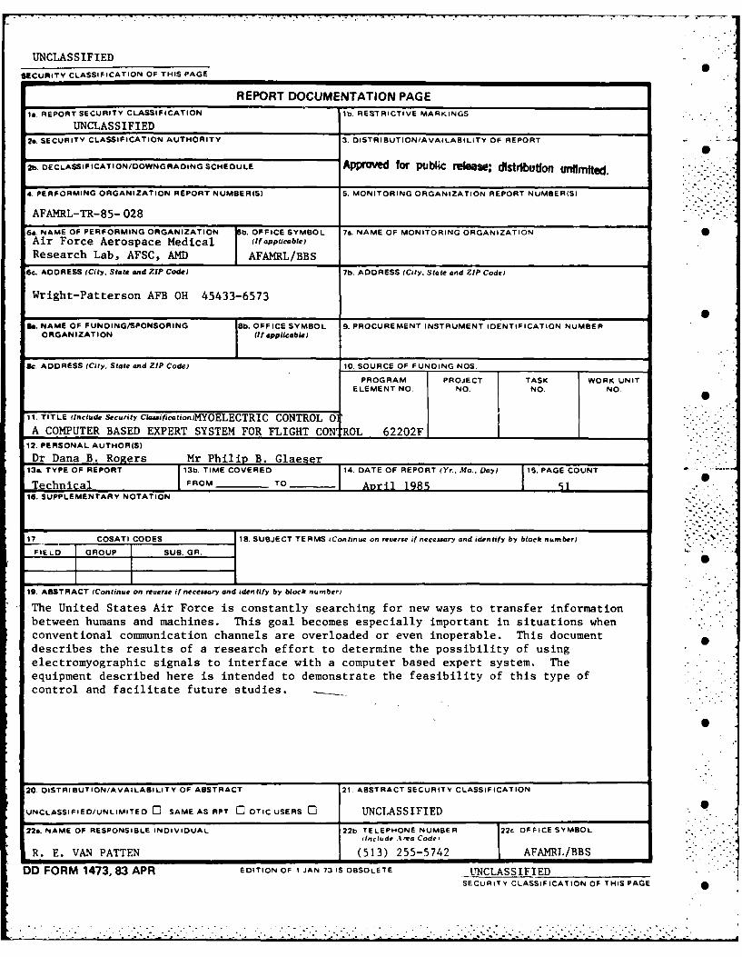
19. ABSTRACT (Continue on reuerse if neceuary and identify by block numbero
The United States Air Force is constantly searching for new ways to transfer information
between humans and machines. This goal becomes especially important in situations whenconventional communication channels are overloaded or even inoperable. This documentdescribes the results of a research effort to determine the possibility of usingelectromyographic signals to interface with a computer based expert system. Theequipment described here is intended to demonstrate the feasibility of this type ofcontrol and facilitate future studies.
20. DISTRIBUTION/AVAILABILITY OF ABSTRACT 21 ABSTRACT SECURITY CLASSIFICATION
UNCLASSIFIED/UNLIMITED 0 SAME AS RPT C1 DTIC USERS C3 UNCLASSIFIED 0
22s. NAME OF RESPONSIBLE INDIVIDUAL 22b TELEPHONE NUMBER 22c OFFICE SYMBOL(include At rra Code o
R. E. VAN PATTEN (513) 255-5742 AFAMRL/BBS
DD FORM 1473, 83 APR EDITION OF I JAN 73 IS OBSOLETE UNCLASSIFIEDSECURITY CLASSIFICATION OF THIS PAGE
Aoession Forr,c NTIS GRA&I
SCOpy DTIC TAB .11 (NS p lkianaouuced [ "--IPECTED nfsond Q
Justification
ABSTRACT D -i'.t "- "''. I V ".
KYOELECTRIC CONTROL OF A COMPUTER BASED EXPERT, ... rSYSTEM FOR FLIGHT CONTRTOL t ,
2*
The United States Air Force is constantly searching for
new ways to transfer information between humans and
machines. This goal becomes especially important in
situations when conventional communication channels are
overloaded or even inoperable. This document describes the
results of a research effort to determine the possibility of
using electromyographic signals to interface with a computer
based expert system. The equipment described here is
intended to demonstrate the feasibility of this type of
control and facilitate future studies.
This ...ork ,'as supported by the Aerospace 1.edical Research
T abcratory (USAF) under contract number F3602-81-C-0206
iii"
S ."-',_
TABLE OF CONTENTS
LIST OF ILLUSTRATIONS .. . .. .. .. .... vi
LIST OF TABLES .... . . . . . . . . . . . . . . . vii
CHAPTER
I. EMG SIGNAL PROCESSING.......... 5
Frequency Analysis ....... 5
Amplitude Analysis . ..... . . . . . 8
II. EMG CONDITIONING BOARD.................12S
III. SPEECH SYNTHESIS BOARD . .... . . . . 19
IV. MICROCOMPUTER INTERFACE. ........ . . 22*.
V. CONTROLLING SOFTWARE . . .. .. .. .... 27 .
Program: SPK-WORD ........... *. 27EG Input Algorithm. ............. 28Program: INP2CH . . . . . . . . . . . . . . 30Program: MENUS.................30
VI. EXPERIMENTATION . . . . . . .. . . . . . . 35
Procedure . . . . . . . . . . . . . . . . . 35Results . . . . . . . . . . . . . 37
VII. CONCLUSIONS AND RECOMMENDATIONS.........38
Summary.. . . . . . . . . . . . . . . 38
Recommnendations . . . . . ... . . . . 38
iv
IS
TABLE OF CONTENTS (continued).
APPENDIX
A SOFTWARELISTING . .. . . .. .. ....... 40
B CIRCUIT BOARD SCHEMATICS ................. 47
BIBLIOGRAPHY .50 ......... s
LIST OF ILLUSTRATIONS
FTCUR PAG
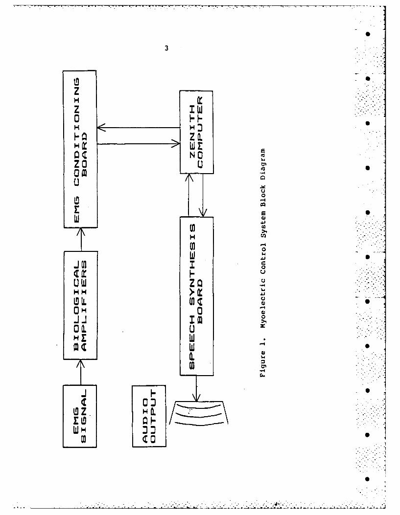
1. Myoelectric Control System Block Diagram ... 3
2. Center Frequency Analysis . . . . . . . . . . . 6
3. Frequency Bin Analysis . . .... . .. . .. 7
4. Typical EMG Signal . ... .. . .. .. . .. 8
5. Comparator Analysis . . . . . . . . . . . . . . 9
6. Integrator Analysis- Variable Time Period . . . 10
7. Integrator Analysis- Constant Time Period . 11
8. EMG Conditioning Board Block Diagram . . . . . 13
9. Electrode Pl e. . .. .. .. .. . . .. 14
10. High Pass Filter . . . . . . . . . . . . . . . 15 -
11. EMG Signal: Tense-Relaxed . . . . . . ... . 16
12. Before-After Filter Comparison . . . ... . 16
13. Rectifier/Integrator . . . . . . . .. .. .... 17
14. Comparator/Voltage Divider . . . . . ... . 18
15. Speech Synthesis Board Block Diagram ... . 20
16. Address Decode Logic ......... . . . . .. 25
17. Read/Write Decode Logic . . . . . . . . . . . . 26
18. EMG Input Algorithm Flowchart . . . . . . . . . 29
19. Menu Scan Flowhrt r. .. .. .. .. . ... 33
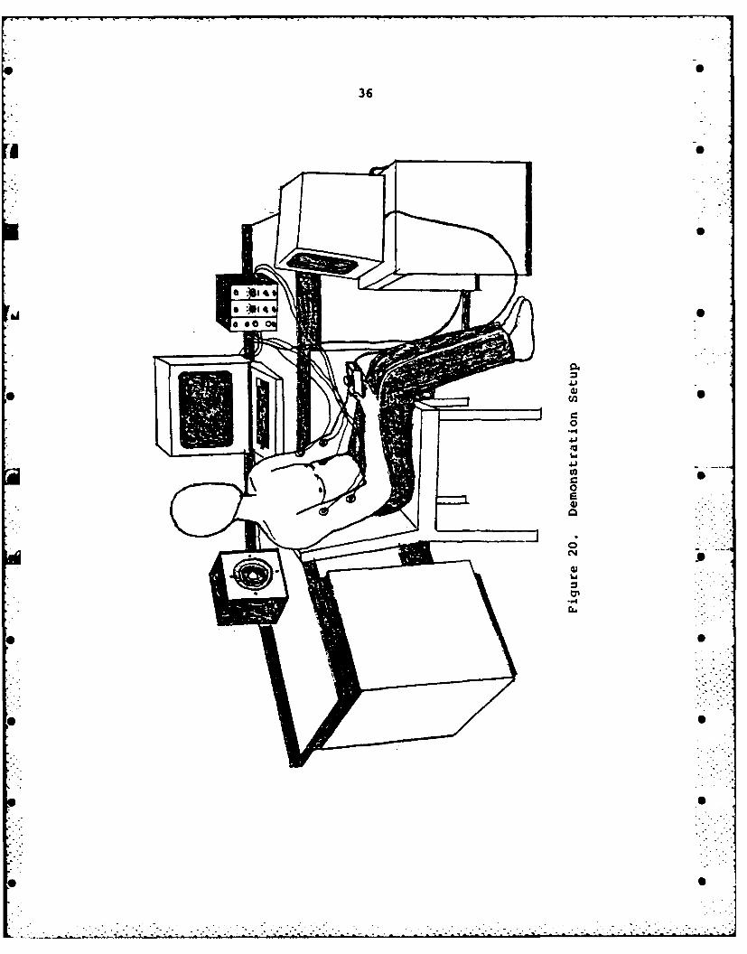
20. DemonstrationSetup... .. .. . . . .. 36
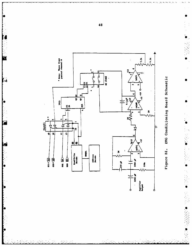
Bl. EMG Conditioning Board Schematic . . . . . . . 48
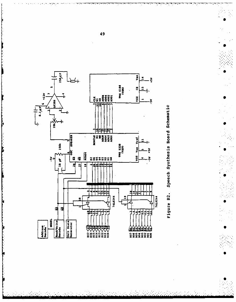
B2. Speech Synthesis Board Schematic .. . . . . . 49
v i
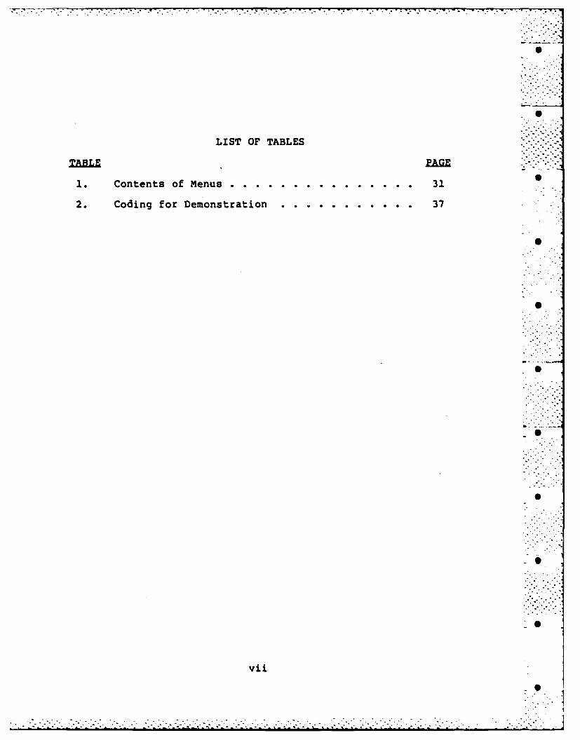
LIST OF TABLES
TBEPAGE 7
1. ContMen. so.. f .. e..n .. 31
2. Coding for Demonstration .. ............................ 37
vii

INTRODUCTION
An electromyographic or EMG signal describes the
electrical voltage which exists in an active muscle. Myo is
a Greek word for muscle. The electrochemical reactions
which are involved in the contraction of a muscle produce O
this voltage. The analysis of this signal has been used for
many purposes including prosthesis control and bioelectric
feedback. Prosthesis applications have shown that EMG
signals can be used for the voluntary control of artificial
limbs. Bioelectric feedback has been used to train airplane
pilots to perform straining maneuvers under high G forces. "
Straining maneuvers are used in order to prevent temporary
vision loss by the pilot.
Since the EMG signal still exists at high G forces, and ,
can be voluntarily controlled, it should be possible to use
the EMG as a means of controlling external devices under
high G forces. Under conditions when even motion is .
difficult, this form of communication can still provide a
working channel between human and machine.
This document describes a laboratory myoelectric
control system which can detect activity in muscles and
convert these signals into a digital format. The muscle -
inputs can then be used for computer control. The purpose B
of thu -thesis is to show that this type of control does
W . . . . .
2
work. In addition, this system is designed with features
that would enable its operation under high G forces. The
block diagram for the myoelectric control system is shown in
figure 1.
Chapter I describes methods of analyzing the raw EMG
signal. By examining the different approaches, a method of
processing the EMG for this system is proposed. The
description of the actual hardware design is the subject of
Chapter II.
Chapter III introduces the speech capabilities of the
system. Both the need for voice feedback and the operation
of the actual hardware are discussed.
The system is based around a Zenith Z-100.
microcomputer. The Zenith supports an S-100 bus system
which provides expansion slots for S-100 breadboards. All
of the interface between the Zenith and additional hardware
is done via the S-l00 bus. The details of how data is
exchanged between the Zenith and the breadboards are
explained in Chapter IV.
The software that controls the entire system is
important for two reasons. First, the software must
maintain complete control of the hardware in order to ensure
reliable operation. Second'ly, it must be able to
effectively use the information it receives in order to make
useful system decisions. Both aspects of the software are
brought out in Chapter V.
,S
. *. 1
0
w H
*j
z IW
H wf___-_ __ __ ZO,.
ZO NDU 0
U m4
uU
wrw
2 H01 . -
H I w
1
c 00W H
OH c3 0 0., . / . . 43 S.: -:.
I- " C" " -"
ono
WZ.-_: .': :. - "_ i .: ; :.2"":'-: - . ."- -": ': .- " - " - : " "S

4
Chapter VI contains descriptions and results of
experiments to test the system. Chapter VII contains
conclusions and recommendations for possible future
applications of this system.
-S i
S
-S ;~ii
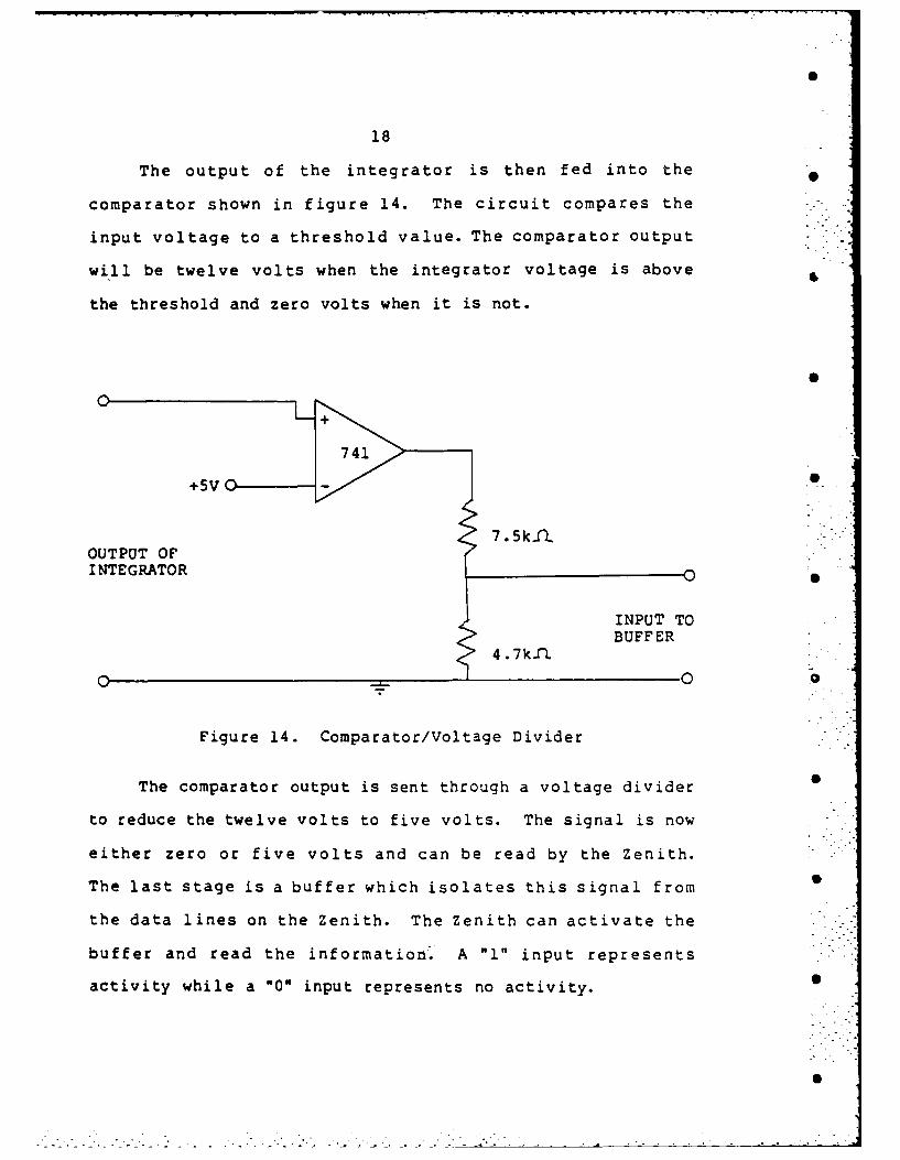
18
The output of the integrator is then fed into the
comparator shown in figure 14. The circuit compares the
input voltage to a threshold value. The comparator output
will be twelve volts when the integrator voltage is above
the threshold and zero volts when it is not.
oS
+5VO
7.5k- -
OUTPUT OFI NTEGRATOR
INPUT TO
BUFFER4.7k1I
0
Figure 14. Comparator/Voltage Divider
The comparator output is sent through a voltage divider B
to reduce the twelve volts to five volts. The signal is now
either zero or five volts and can be read by the Zenith.
The last stage is a buffer which isolates this signal from
the data lines on the Zenith. The Zenith can activate the
buffer and read the information. A "1" input represents
activity while a "0* input represents no activity. .
Si
0
17
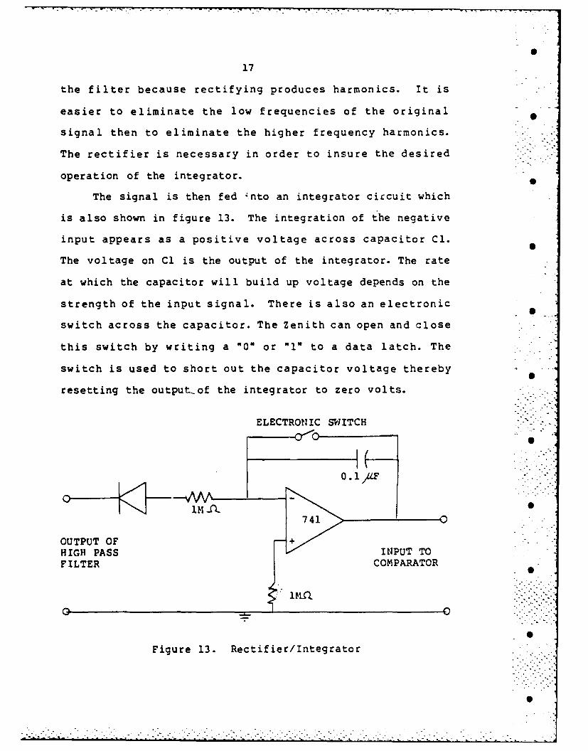
the filter because rectifying produces harmonics. It is
easier to eliminate the low frequencies of the original 0
signal then to eliminate the higher frequency harmonics.
The rectifier is necessary in order to insure the desired
operation of the integrator.
The signal is then fed 'nto an integrator circuit which
is also shown in figure 13. The integration of the negative
input appears as a positive voltage across capacitor Cl.
The voltage on Cl is the output of the integrator. The rate
at which the capacitor will build up voltage depends on the
strength of the input signal. There is also an electronic
switch across the capacitor. The Zenith can open and close
this switch by writing a "0" or "l" to a data latch. The
switch is used to short out the capacitor voltage thereby
resetting the output-of the integrator to zero volts.
ELECTRONIC SWITCH -
0.1 AF --741O -------
OUTPUT OF +HIGH PASS > INPUT TOFILTER COMPARATOR
Figure 13. Rectifier/Integrator
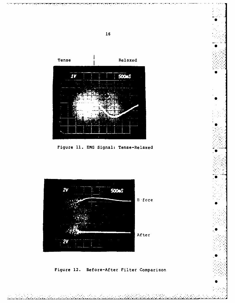
16
Tense IRelaxed
Figure 11. EMG Signal: Tense-Relaxed
D ffore
After
Figure 12. Before-After Filter Comparison
15
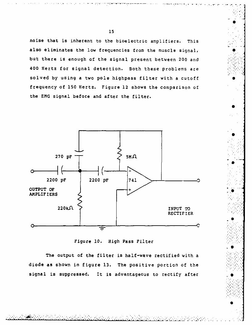
noise that is inherent to the bioelectric amplifiers. This
also eliminates the low frequencies from the muscle signal, S
but there is enough of the signal present between 200 and
400 Hertz for signal detection. Both these problems are
solved by using a two pole highpass filter with a cutoff S
frequency of 150 Hertz. Figure 12 shows the comparison of
the EMG signal before and after the filter.
270 pF 5M"
0 •
2200 pF 2200 pF 741
OUTPUT OF +AMPLIF IERS
220 kA INPUT TORECTIFIER
S
Figure 10. High Pass Filter
The output of the filter is half-wave rectified with a
diode as shown in figure 13. The positive portion of the
signal is suppressed. It is advantageous to rectify after
. . , . . .
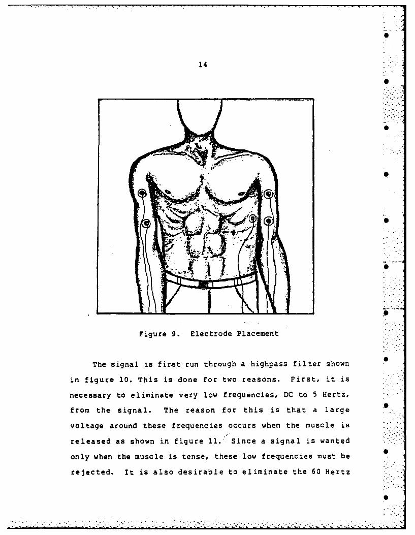
14
Figure 9. Electrode Placement
The signal is first run through a highpass filter shown
in figure 10. This is done for two reasons. First, it is
necessary to eliminate very low frequencies, DC to 5 Hertz,
from the signal. The reason for this is that a large
voltage around these frequencies occurs when the muscle is
released as shown in figure 11. Since a signal is wanted
only when the muscle is tense, these low frequencies must be
rejected. It is also desirable to eliminate the 60 Hertz
fromthesigal.The easn fr tis i tht alare °
. ° .. "
13
w -
o S
0 w z 3
00
w ..
0' 0
0 M c
u -.
I3 w
0 1'
* . .. - . .°.
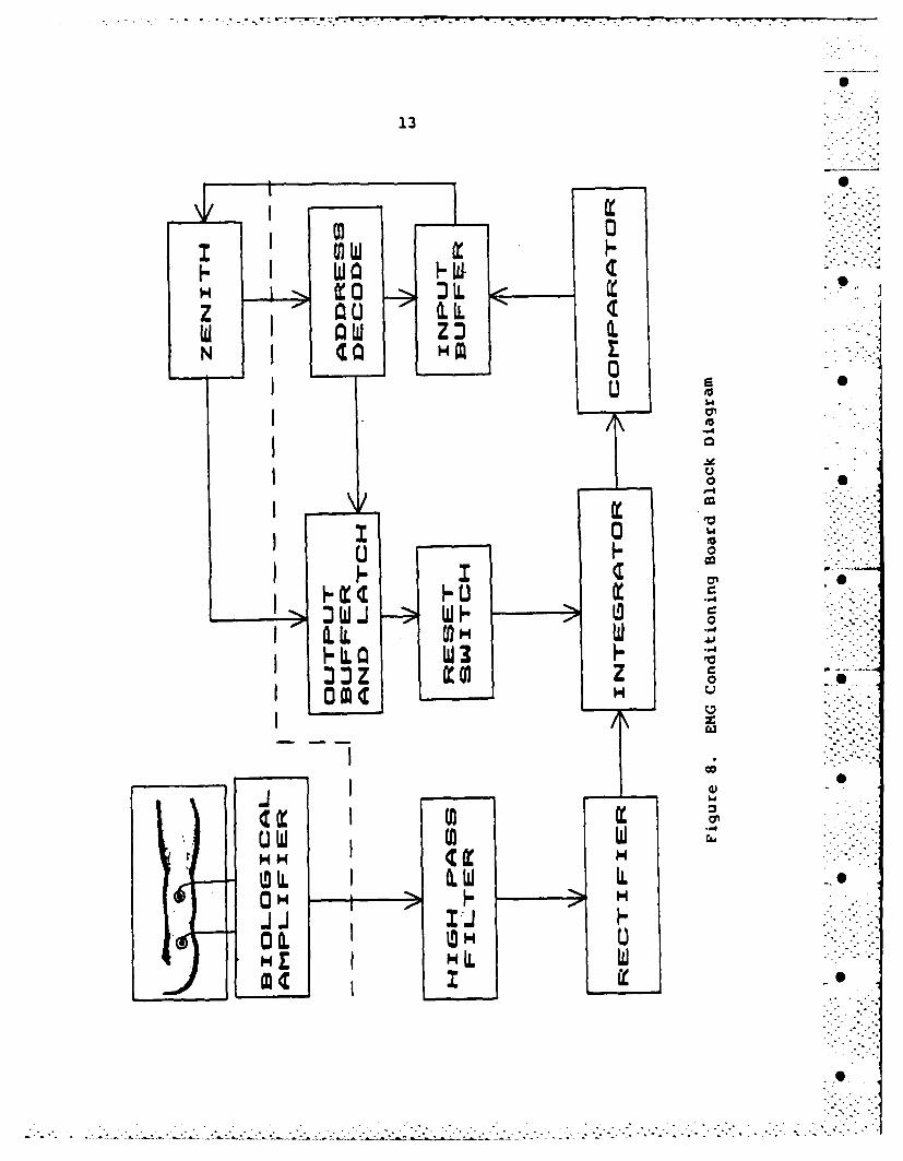
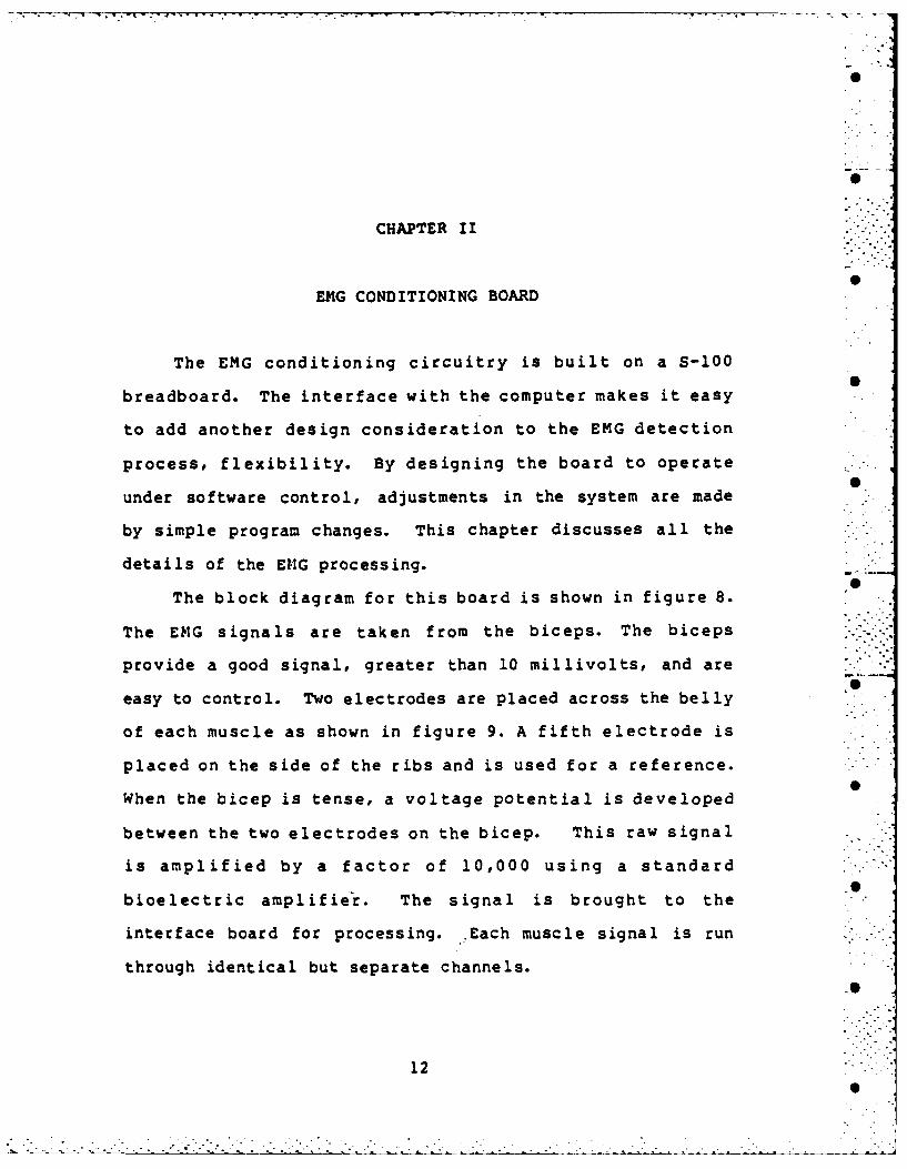
CHAPTER II
EMG CONDITIONING BOARD
The EMG conditioning circuitry is built on a S-100
breadboard. The interface with the computer makes it easy
to add another design consideration to the EMG detection
process, flexibility. By designing the board to operate
under software control, adjustments in the system are made
by simple program changes. This chapter discusses all the
details of the E1Z4G processing.
The block diagram for this board is shown in figure 8.
The EMG signals are taken from the biceps. The biceps
provide a good signal, greater than 10 millivolts, and are
easy to control. Two electrodes are placed across the belly
of each muscle as shown in figure 9. A fifth electrode is
placed on the side of the ribs and is used for a reference.
When the bicep is tense, a voltage potential is developed
between the two electrodes on the bicep. This raw signal
is amplified by a factor of 10,000 using a standard
bioelectric amplifier. The signal is brought to the
interface board for processing. .Each muscle signal is run
through identical but separate channels.
12
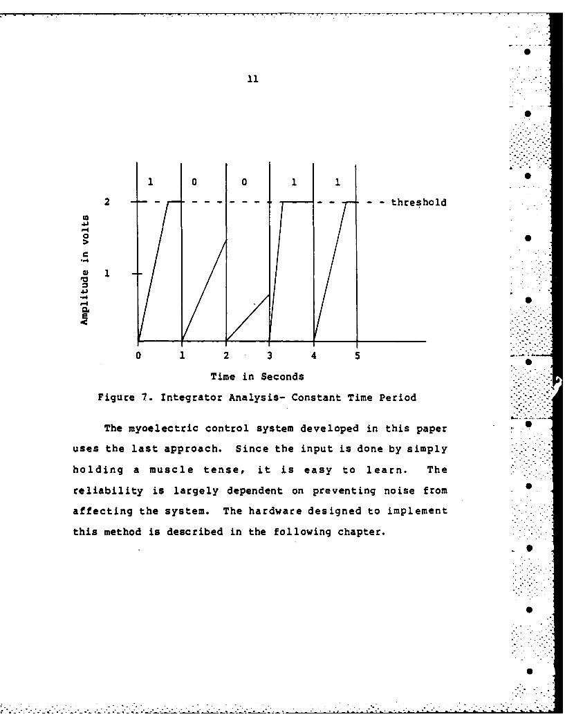
11
1 0 01 10
2 ---- -- threshold
°..'
0
"4 /
0 1 2 3 4 5 -
Time in Seconds
Figure 7. Integrator Analysis- Constant Time Period
The mycelectric control system developed in this paper
uses the last approach. Since the input is done by simply
holding a muscle tense, it is easy to learn. The
reliability is largely dependent on preventing noise from
affecting the system. The hardware designed to implement
this method is described in the following chapter.
S
• ° - - " .
0 -
-" - - - •
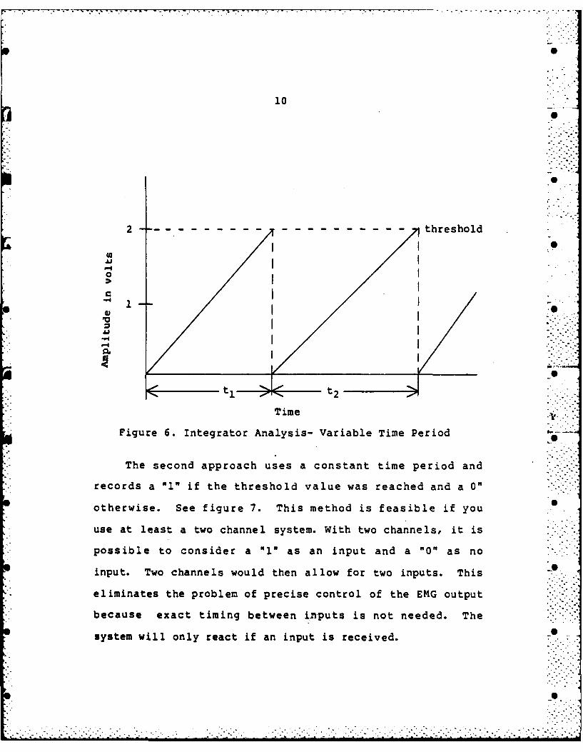
10
2 ----------- ---------- thresholdSI I
0I tI
Time Al
Figure 6. Integrator Analysis- Variable Time Period
The second approach uses a constant time period and
records a 0" if the threshold value was reached and a 0"
otherwise. See figure 7. This method is feasible if you
use at least a two channel system. With two channels, it is
possible to consider a "l" as an input and a "0" as no
input. Two channels would then allow for two inputs. This 0
eliminates the problem of precise control of the EMG output
because exact timing between inputs is not needed. The "
system will only react if an input is received. o
.S* " =
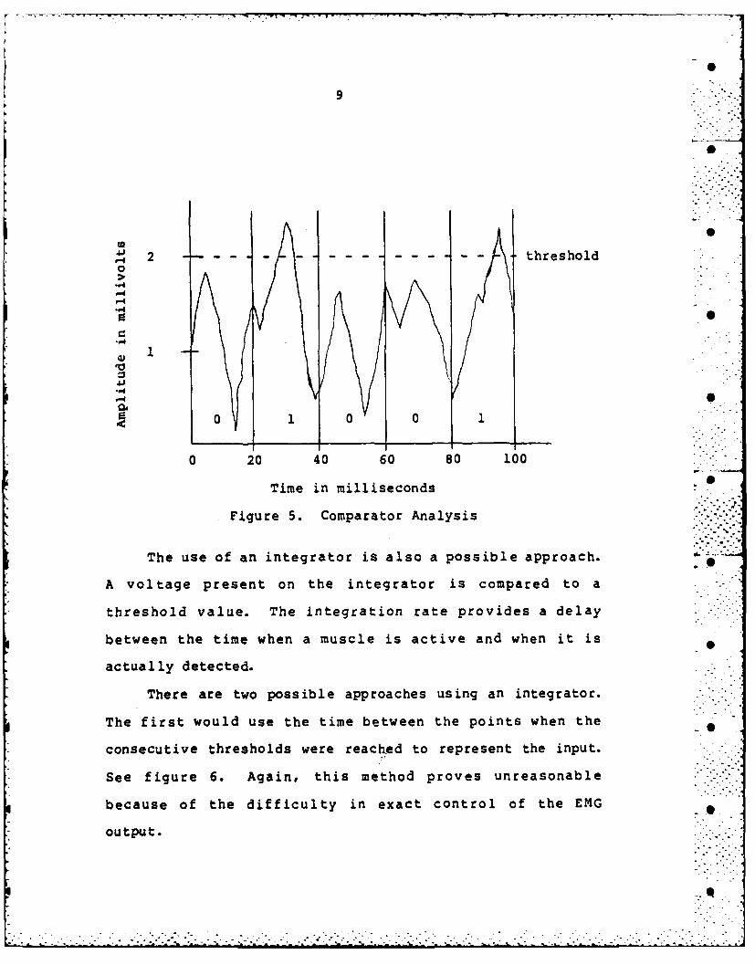
90
2 threshold0
-4
..4IA
50 1 0 01
0 20 40 60 80 100
Time in milliseconds 5
Figure 5. Comparator Analysis
The use of an integrator is also a possible approach.
A voltage present on the integrator is compared to a
threshold value. The integration rate provides a delay
between the time when a muscle is active and when it is
actually detected.
There are two possible approaches using an integrator.
The first would use the time between the points when the -
consecutive thresholds were reachjed to represent the input.
See figure 6. Again, this method proves unreasonable .
because of the difficulty in exact control of the EMG
output.
0S
8
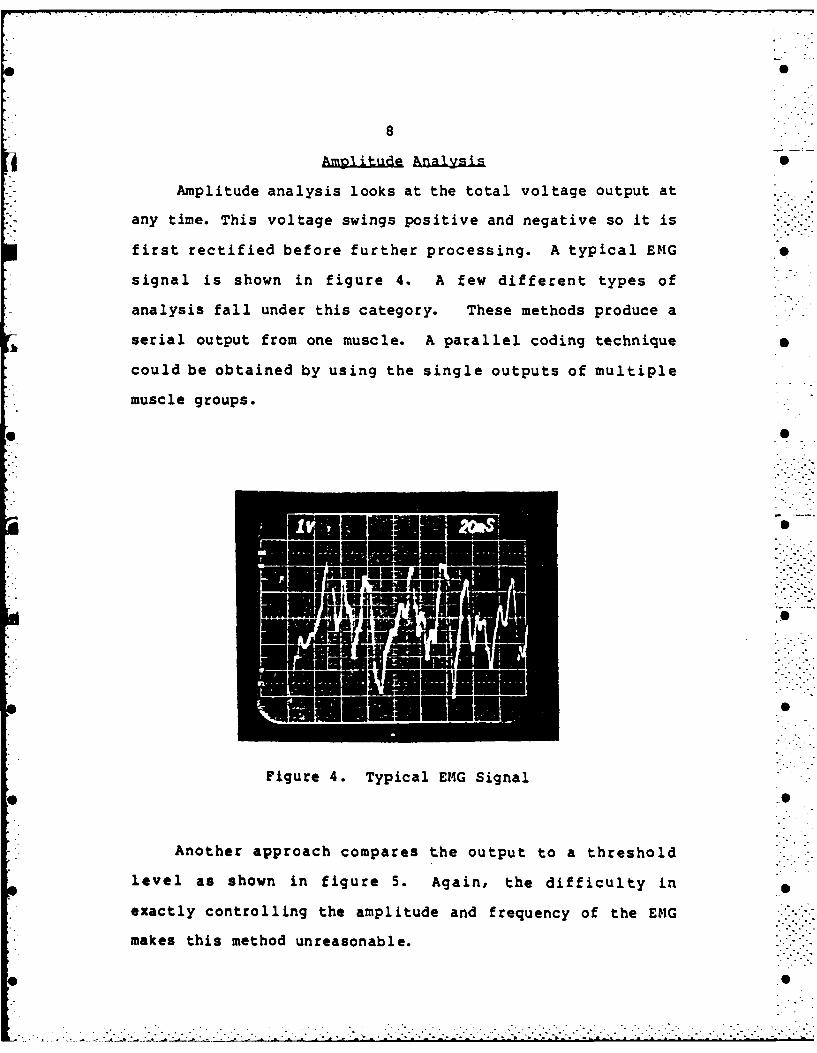
Am~1itkue Anaysis
Amplitude analysis looks at the total voltage output at
any time. This voltage swings positive and negative so it is
first rectified before further processing. A typical EMG
signal is shown in figure 4. A few different types of
analysis fall under this category. These methods produce a
serial output from one muscle. A parallel coding technique
could be obtained by using the single outputs of multiple
muscle groups.
Fiur 4.Tpcl6GSga
leve as howFiur 4.ur Typca Aginalh dfiulyi
exactly controlling the amplitude and frequency of the ENG
makes this method unreasonable.
7
004J+
wI
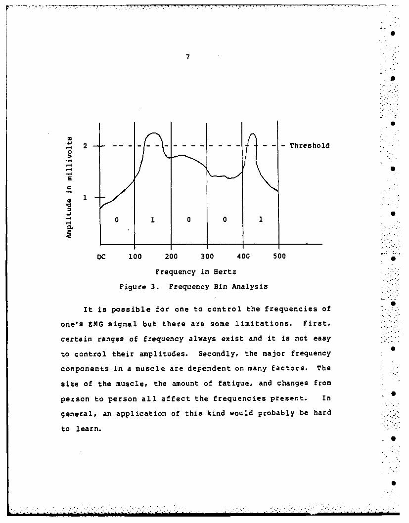
Figure~~~~ 3. Frqec inAayi
2e 2-------------------------------------- .- Threshold
0
E
.1i0 1 00 1+
DC 100 200 300 400 500
Frequency in Hertz -
Figure 3. Frequency Bin Analysis
It is possible for one to control the frequencies of . .
one's EMG signal but there are some limitations. First, "'
certain ranges of frequency always exist and it is not easy
to control their amplitudes. Secondly, the major frequency
conponents in a muscle are dependent on many factors. The
size of the muscle, the amount of fatigue, and changes from
person to person all affect the frequencies present. In
general, an application of this kind would probably be hard
to learn.
S+
S
. . . .. . . . .*
I
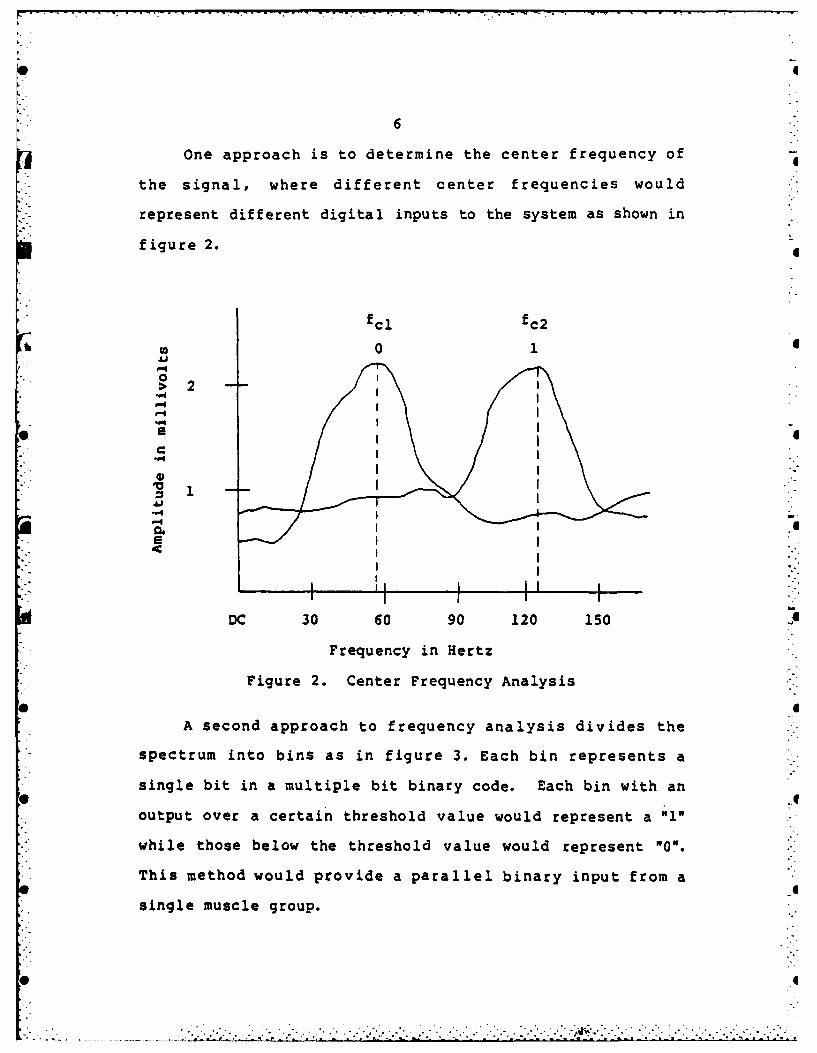
6
One approach is to determine the center frequency of
the signal, where different center frequencies would
represent different digital inputs to the system as shown in
figure 2.
fcl fc2
in 01
00I>2i I
.4
Ji 2I-
-* I I ""II
I-..I
:: tI I I' I ::DC 30 60 90 120 150
Frequency in Hertz
Figure 2. Center Frequency Analysis
A second approach to frequency analysis divides the
spectrum into bins as in figure 3. Each bin represents a
single bit in a multiple bit binary code. Each bin with an* .6output over a certain threshold value would represent a "I"
while those below the threshold value would represent "0".
This method would provide a parallel binary input from a
single muscle group.
-'.::, .. . ...., . *...... .. .'.2--.... .-. -.... . .... *:-. --.-...?,. .-.
CHAPTER I
*EMG SIGNAL PROCESSING
The detection and processing of the EM4G signal is the
most important aspect of the system. The method chosen must
be reliable. In addition, the operation of the system needs
to be easy to learn and perform. By meeting these
* conditions, the system will be effective in a variety of
environments.
An EMG signal has an amplitude of a few millivolts and
contains various frequencies concentrated between DC and 400
Hertz. The center frequency is usually between 50 and 70
Hertz. Many methods of analyzing the signal are available.
An overview of a few of these methods will develop a feel
for the problems involved in analyzing the EKG.
Frgunca. Analysis
Frequency analysis involves. determining the amplitudes
of each frequency component in the signal. This can be done,
for example, by analog filters, digital filters, or a
Fourier transform process. Two methods of interpreting the
results are discussed here.
5
CHAPTER III
SPEECH SYNTHESIS BOARD
The user needs feedback to help him maintain control of
the system. In addition to the visual feedback on the
monitor, an audible feedback of high quality speech is also
provided. Audio is included for two reasons. First, it
does not require constant attention. The user can be
concentrating on other tasks and still have immediate
knowledge of the system's activity. Secondly, the eyes fail
at a lower G level than the ears. Under high G conditions,
a speech system may be the primary form of feedback.
The speech synthesis board is based on the TMS 5220
voice synthesis processor (VSP), and its associated memory
chip, the TMS 6100 voice synthesis memory (VSM). The TMS
5220 uses linear predictive coding to produce high quality
speech. The TMS 6100 is a 128-kilobit ROM. The four ROMs
in this system provide a vocabulary of over 450 words. This
system is TTL compatible and easily interfaced to a
microcomputer.
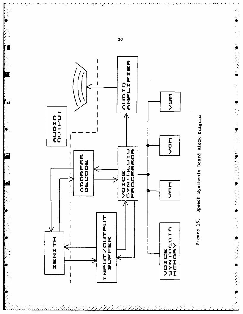
The block diagram of this c:ircuit is shown in figure
15. (Note that D7 is the least significant data line on the
TMS 5220.)
19
20
000
HIa:0
XA 00~
I~~ I x-Z u )
La S4ZN 0 > w
z0
b0
21
To initiate speech, the Zenith sends four hexadecimal
numbers to the VSP. These numbers represent a memory
location in the VSM. The code for one word starts at this
location. The Zenith then sends a "Speak" command and the
VSP uses the addressed code to create an audio output. The 0
Zenith continues to monitor the status of the VSP until the
speech process is completed. The Zenith then resets the VSP
and initiates another word or continues on with other 0
programming.
• S o
,. .
-.......... .... ......................-
CHAPTER IV
MICROCOMPUTER INTERFACE
For this system, the Zenith runs all software on an
8088 microprocessor. The 8088 also acts as the master of
the S-100 bus. A master is the device which controls the
bus. All other devices are controlled by the master and are
called slaves. A slave receives data from or sends data to
the bus master. Slaves are separated into two types, memory
devices and input/output or I/0 devices. Both the EMG
conditioning board and the speech synthesis board are I/O
devices.
Most signals on S-100 bus are either input or output
lines. The master sends information out on the output lines
and receives information on the input lines. In addition,
one special utility line is used. The following lists each
line used with its S-100 pin number and a description of its
function.
Input Lines
DIO-DI7 Pin Numbers: 95,94,41,42,91,92,93,43(Data lines) Description: DIO-DI7 is an eight bit
path to input data to the master. DIOis the least significant bit.
RDY Pin Number: 72 Active: High 0(Ready) Description: RDY is asserted high by a
slave to tell the master it is readyto complete the current bus cycle... .
22
23
Output Lines
AO-A7 Pin Numbers: 79,80,81,31,30,29,82,83(Address Lines) Description: AO-A7 is an eight bit
path used to address slaves. AO isthe least significant bit.
DOO-DO7 Pin Numbers: 36,35,88,89,38,39,40,90(Data Lines) Description: DOO-D07 is an eight bit
path to output data from the master.DOO is the least significant bit.
sINP Pin Number: 46 Active: High(status INPut) Description: This line is active when
the master is executing an inputcycle and reading data from an I/Oport address.
sOUT Pin Number: 45 Active: High(status OUTput) Description: This status line is
active when the master is executingan output cycle and writing data toan I/O port address.
pWR* Pin Number: 77 Active: Low(processor Description: pWR* is used to tell theWRite) slave when the data on the data
output bus is valid.
pDBIN Pin Number: 78 Active: High(processor Description: pDBIN is used to tell theData Bus IN) slave when to place its data on the
data input bus.
pSYNC Pin Number: 76 Active: High(processor Description: This is a strobe thatSYNChronize) indicates the start of every bus
cycle. It becomes active near thebeginning of every bus cycle andremains active for one clock cycle.
Utility Line
POC* Pin number: 99 Active: Low(Power On Clear) Description: POC* starts out low when
the system powers up and remains lowfor at least 10 milliseconds. It isused to insure that all hardware isinitiated in the proper state.
-- .. • -,..
24
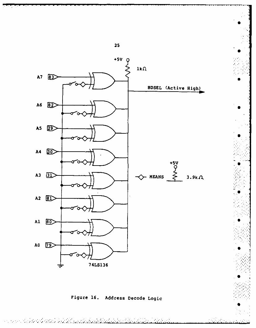
Each board has circuitry to decode the address lines as
shown in figure 16. Each address line is connected to the
input of an exclusive or gate. The other input to the gate
is connected to a combination of a switch and a pull-up
resistor. Considering a closed switch to represent logic 1 0
and an open switch logic 0, the signal on the address line
must match the switch to create a high output from the
exclusive or gate. The outputs of all eight gates are B
connected together along with a pull-up resistor. The
output of all gates must be high in order for the board
select signal, BDSEL, to be high. 0
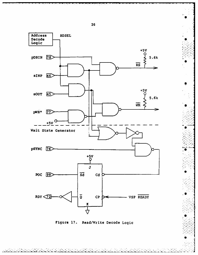
The BDSEL signal is combined with status and control
signals to determine the proper I/O operation. Figure 17
shows the read/write decode logic of the speech synthesis
board. Similar circuitry is used on the EIG conditioning
board except for the section labeled "Wait State Generator"
which is only present on the speech board. This added S
circuitry is necessary because the VSP cannot transfer data
as quickly as the 8088 can. The Wait State Generator delays
the read or write cycle of the 8088 until the VSP is ready B
to complete the data transfer.
When read or write operation is decoded by a board, the
buffer which isolates the computer's data lines from the
board is taken out of the high impedance state. This
connects the computer and board data lines together and
transfer of information can take place.
•S S •.
25
+SS
DDSEL (Active High)
A6S
ASS
A3MEANS 3.9kfl.
- 74LS136
Figure 16. Address Decode Logic
26
Address BDSELDecodeLogic
+5V
pDBIN 5.6
TsS
sINS
Wait State Generator *
pSYNC
Figure 17. Read/Write Decode Logic
CHAPTER V
CONTROLLING SOFTWARE -
The software for this system performs two functions.
First, it controls the operation of both the E1.G B
conditioning board and the speech synthesis board.
Secondly, it uses the decision making ability of the Zenith
in conjunction with the inputs from the EMG conditioning --
board to determine the system's output. In this manner, the
Zenith is used as the basis of an expert system. This
section reviews three programs and one algorithm which are
used to test and run the system.
Program- Si-R .
SPK-WORD is short for Speak-word. It is an interactive
program used to control the speech synthesis board. The
program prompts the user to input the hexadecimal address of - •
the word to be spoken. The program then manipulates the
input into the form the VSP requires and outputs the data.
The word is spoken and the program prompts for another
input. The routines used in this • program are used for all
programs which make use of the speech synthesis board. A
listing of this program is found in Appendix A. B
27
28
ET nu Aithbm
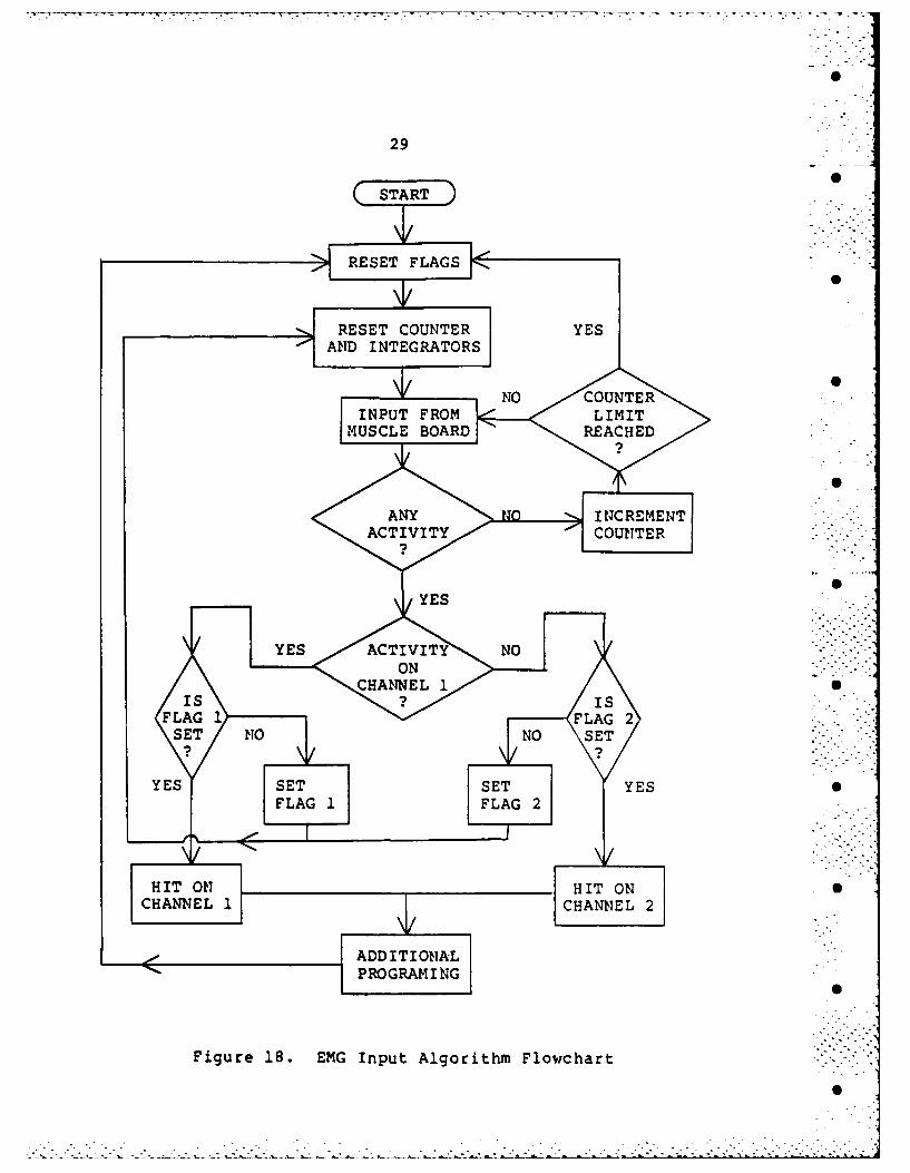
This algorithm controls the inputs from the EMG
conditioning board. An input from this board is referred to
as a nhit". This algorithm is flowcharted in figure 18. Its
operation is also described below.
One flag variable is used for each channel. The
algorithm initializes the system by resetting the flags, the
integrator voltage, and a counter. The output of each
channel is read in and checked for activity. If no activity
is found, the counter is advanced. The counter is then
checked to see if a limit is reached. if the limit was not
reached, the program goes back and checks the output of each
channel again. This process will continue if no input is
present until the counter reaches its limit. The program
will then go back to the start state. In this manner, the
counter limits the amount of time the integrator has to
build up voltage. This process proves to be very effective
in stopping noise f rom activating the EI4G board's output.
If activity is found on a channel, the f lag for that
channel is set to logical one. The program then resets the
counter and the integrator voltage to zero and checks for
more activity. If a channel is found to be active two times
in a row, then a "hit" will be recognized on this channel.
Using the f lags forces the muscl. to be tense for a longer
period of time which helps prevent erroneous inputs.
o- i
29
START
RESET COUNTER YE
AND NTEGATOR
YES

30
Progame NP2C
INP2CH stands for Input two Channels. It is listed in
Appendix A. This program enables the user to become
familiar with the operation of the EMG board and provides
for preliminary testing of the EMG input circuitry. it
displays the activity of each channel as either a "1" or a
NON on the screen. The Zenith beeps when a hit occurs. A
brief message is also displayed telling the user on which
channel the last hit occurred. In this manner, the user can
determine the required force and length of tension which he
needs to apply to have the computer recognize an input. It
is also useful to determine how quickly a series of inputs
can be given to the computer.
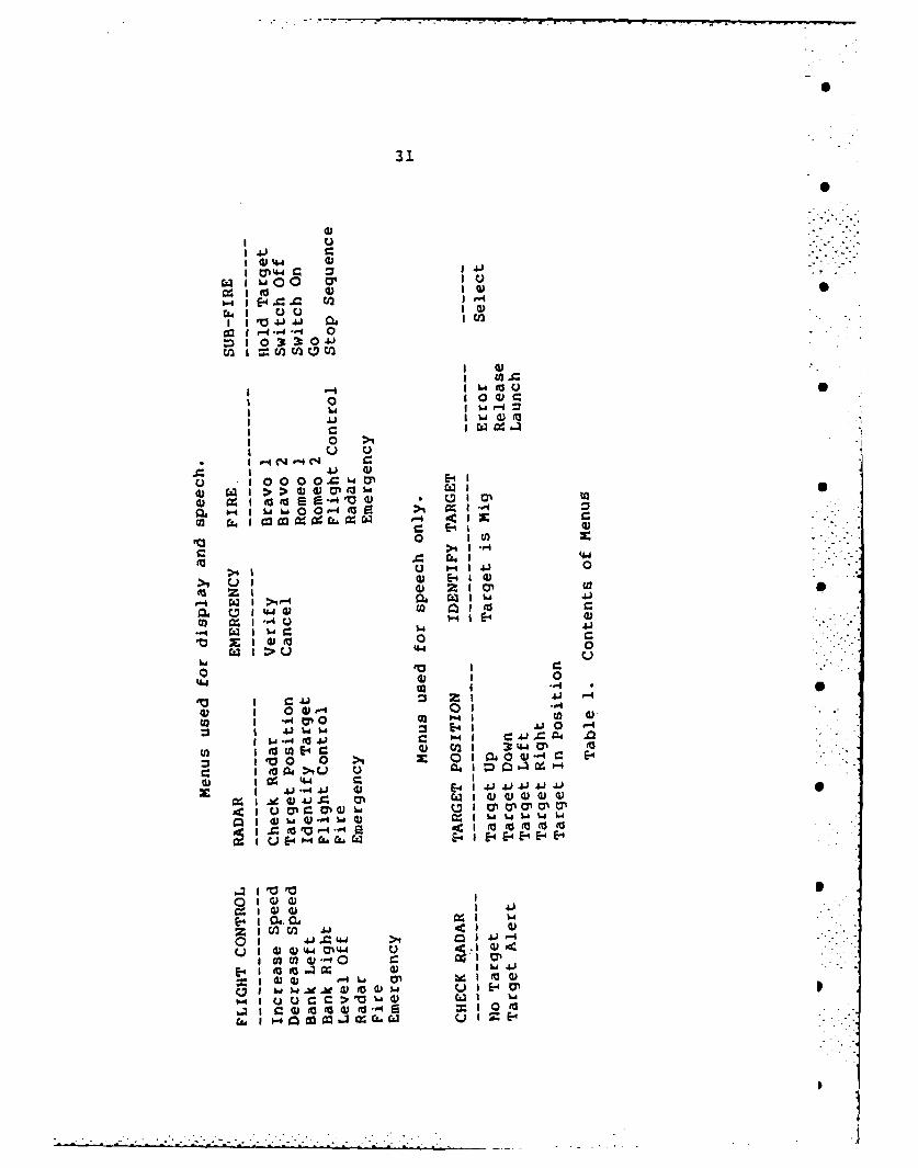
Brgam! MENUS
MENUS is a program which simulates the use of the
system to control a fighter aircraft. This program is also
listed in Appendix A. As the name implies, this program
consists of a series of menus. The menus are arranged in a
matrix format as shown in Table 1. The instructions on each
menu are used to control various aspects of the plane's
operation. Ten separate menus are used. The operation of
the program is explained below.
There are four matrices which are initialized at the
beginning of the program. The first is a string matrix
which contains the word which will be printed on the
monitor. The second is a numeric matrix which holds the
31
44 .: 4 "
0 01 4144
41 -
.-4, -4
1 0 3 ,3.0 4j.
r~i 0
SI .,3 ,0O
I 4-
I ' I8 '2
0IO41C0 ' .
I hiI ..... Ih& , 9.i4..2
i I ,C ' - _l
I 0- > I0 ' "
c w 44 .,-
CJ0
q C4 f-4C.14 "
0 *0 0 0h E
c1 ok 144
C% z~ 41z
02 ..C~l-. C • .-
-. - - .- 0 .--4 w I w1 f44
0 110
Li CDC4a-
_4 0, 0- U
0 Ai %AJ %A E- 2 --4 i41 "03 j w .
02 0 *.1 la2 o (u -- 4C E
tc w I U 0 CI IJ
aV 1 04 >j 41l i0 1 E-4 4-A J
41 ~ 4-i JC a%
AC I tr ci 4) U4hiI~ 020w0202d)
V V
Z I C/IC (v
41 41 %J
w I e w (D t w -1 h
~~C- I E-40212 ~ 10
32
number corresponding to the color to be used to display the
word. The color of each word is used to determine if the
instruction has been removed from the menu. The third
contains the number of words to be spoken with each
instruction. The fourth is a three dimensional string
matrix which holds the hexadecimal addresses of the words in
the VSM.
The row number of each column represents a different
instruction. Only one instruction on one menu is active at
any time. The computer keeps track of the current location
in the matrix by the row and column numbers.
The program always has two options. The first allows
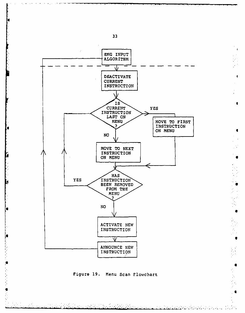
you to move to the next instruction on the menu. This
operation follows the flowchart shown in figure 19.
The second option selects the instruction which is
currently active. If this option is taken, the computer
first acknowledges the selection by saying "select". It
then determines the proper function by checking the row and
column numbers. Based on these numbers, the program
branches to a subroutine. Once the subroutine is complete,
the program returns to the EMG input algorithm.
The functions performed are only limited by the
capabilities of the computer. The ability to control
external circuitry is already shown by the speech board.
Extending this control to power devices, motors, etc., is
a simple process.
S
APPENDIX B
CIRCUIT BOARD SCHEMATICS
47S
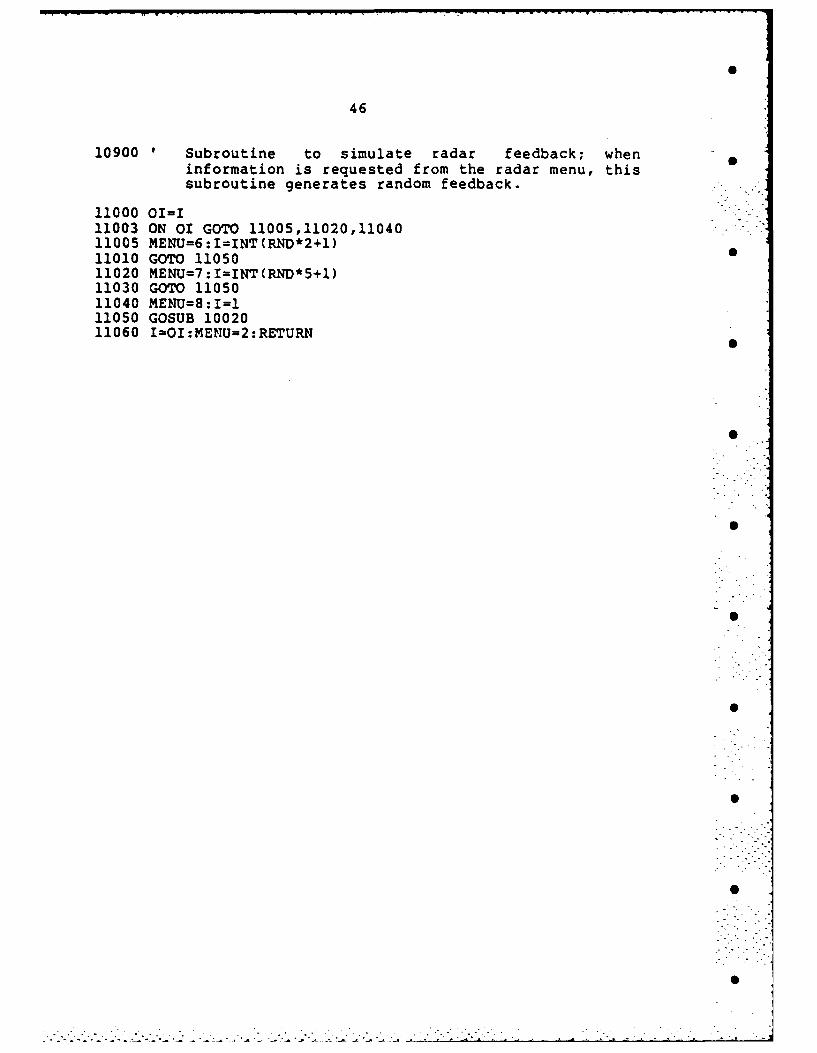
46
10900 Subroutine to simulate radar feedback; wheninformation is requested from the radar menu, thissubroutine generates random feedback.
11000 01=111003 ON 01 GOTO 11005,11020,1104011005 MENU=6:IINT(RND*2+1)11010 GOTO 1105011020 MENU=7:I=INT(RND*5+1)11030 GOTO 1105011040 MENU=J8:I1=111050 GOSUB 1002011060 I101:MENUJ2:RETURII
45
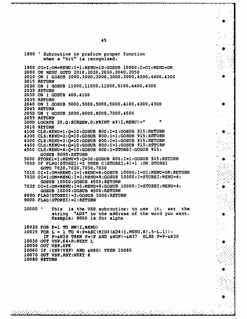
1800 'Subroutine to preform proper functionwhen a "hit" is recognized.
1900 OI=I:OM=MENU:I11:MENU=10:GOSUB 10000:I=OI:MEIVUOM2000 ON KENU GOTO 2010,2020,2030,2040,20502010 ON I GOSUD 3000,3000,3000,3000,3000,4200,4400,430002015 RETURN2020 ON I GOSUB 11000,11000,11000,5100,4400,43002025 RETURN2030 ON I GOSUB 400,41002035 RETURN2040 ON I GOSUB 5000,5000,5000,5000,4100,4200,43002045 RETURN2050 ON I GOSUB 3000,9000,8000,7000,45002055 RETURN3000 LOCATE 20,Q:SCREEN,0:PRINT A$(I,MENU)+"3010 RETURN4100 CLS:MENUm1:QinlO:GOSUB 800:1-1:GOSUB 915:RETURN4200 CLS:MENU-2:Q-10:GOSUB 800:1=1:GOSUB 915:RETURN4300 CLS:MENU-3:QinlO:GOSUB 800:Iu1:GOSUB 915:RETURN4400 CLS:MENU-4:Q-10:GOSUB 800:1=1:GOSUB 915:RETURN4500 CLS:MENU-4:0 10:GOSUB 800:I=STOREI:GOSUB 915:
GOSUB 9000:RETURN5000 STOREI-I:MEDIU-5:Q=30:GOSUB 800:1-1:GOSUB 915:RETURN7000 IF FLAG(STOREI)3 THEN C(STOREI,4)1l :ON STOREI
GOTO 7020,7020,7030,70307010 OI=I:OM-MENU:I=1:MENU-9:GOSUB 10000:I=OI:MENUrnOM:RETURN -
7020 OIiI:OM-MENU:1I-2:MEINU-9:GOSUB 10000:I=STOREI:MENU=4:GOSUB 10000:GOSUB 4500:RETURN
7030 OIuiI:OMENU:-3:METU-9:GOSUB 10000:I=STOREI:MENU=4:GOSUB 10000:GOSUB 4500:RETURN
8000 FLAG (STOREI) 3 :GOSUB 3000 :RETURN9000 FLAG (STOREI) -1:RETURN
10000 ' This is the VSP. subroutine; to use it, set thestring "ADS to'the address of the word you want.Example: 8000 is-for alpha
10020 FOR K-i TO NW(I,MENJ)10025 FOR L - 1 TO 4:P-ASC(MID$(AD$(I,MENU,K),5-L,1)):
IF P>&H39 THEN P-(P AND &HDF)-&H37 ELSE P=P-&H3010030 OUT VSP,64+P:NEXT L10050 OUT VSP,SPK10060 IF (INP(VSP) AND &H80) THEN 1006010070 OUT VSP,RST:NEXT K10080 RETURN
44
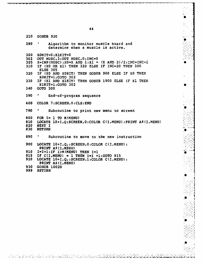
210 GOSUB 920
290 Algorithm to monitor muscle board anddetermine when a muscle is active.
300 XOHIT-O:XlHIT=0 "-.302 OUT MUSC,3:OUT MUSC,0:INC-0305 X-INP(MUSC):XO=X AND l:Xl = (X AND 2)/2:INC=INC+I 0310 IF (X0 OR Xl) THEN 320 ELSE IF INC=20 THEN 300
ELSE 305320 IF (XO AND XOHIT) THEN GOSUB 900 ELSE IF XO THEN
XOHIT=:GOTO 302330 IF (Xl AND XlHIT) THEN GOSUB 1900 ELSE IF Xl THEN
XIHIT=I:GOTO 302 S340 GOTO 300
390 ' End-of-program sequence
400 COLOR 7:SCREEN,0:CLS:END
790 ' Subroutine to print new menu to screen
800 FOR I= 1 TO M(MENU)810 LOCATE 10+I,Q:SCREEN,0:COLOR C(I,MENU):PRINT A$(I,MENU)820 NEXT I830 RETURN
890 ' Subroutine to move to the new instruction
900 LOCATE 10+I,Q,:SCREEN,0:COLOR C(I,MENU):PRINT A$(I,MENU)
910 11+:IF I>M(MENU) THEN I-l 1915 IF C(I,MENU) = 1 THEN I-I +I:GOTO 915920 LOCATE 10+I,Q,:SCREEN,I:COLOR C(I,MENU):
PRINT A$(I,MENU)930 GOSUB 10020999 RETURN
.. .." "
2 .S I-.
S
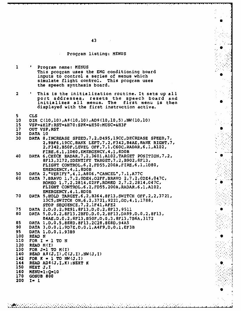
43
Program listing: MENUS
1 Program name: MENUSThis program uses the EMG conditioning boardinputs to control a series of menus whichsimulate flight control. This program usesthe speech synthesis board.
2 'This is the initialization routine. It sets up allport addresses, resets the speech board andinitializes all menus. The first menu is thendisplayed with the first instruction active.
5 CLS10 DIN C(l0,l0),A$(l0,l0),AD$(10,l0,5),NW(10,l0)15 VSP=&HlF: RST-&H70 :SPK=&H50 :MUSC=&H3F17 OUT VSP,RST20 DATA 1030 DATA 8,INCREASE SPEED,7,2,D495,19CC,DECREASE SPEED,7,
2,9BF6,l9CC,BANK LEFT,7,2,F342,B4AE,BANK RIGHT,7,2,F342,B50F,LEVEL OFF,7,l,C6OC,RADAR,6,l,A102,FIRE,6,1,1D80,EMERGENCY,4,1,8DOB
40 DATA 6,CHECK RADAR,7,2,3601,A102,TARGET POSITION,7,2,8F13,3172,IDENTIFY TARGET,7,2,B902,8Fl3,FLIGHT CONTROL,6,2,FD55,200A,FIRE,6 ,l,1D80,EMERGENCY,4,1,8DOB
50 DATA 2,"VERIFY",4,l,A806,"CANCEL",7,l,A77C60 DATA 7,BRAVO 1,7,2,ODE4,O2FF,BRAVO 2,7,2,ODE4,047C,
ROMEO l,7,2,2814,O2FF,ROMEO 2,7,2,2814,047C,FLIGHT CONTROL,6,2,FD55,200A,RADAR,6,1,A102,EMERGENCY,4 ,l,8DOB
70 DATA 5,HOLD TARGET,6,2,B364,8F13,SWITCH OFF,2,2,3721,13CS,SWITCH ON,6,2,3721,9221,GO,4,l,1788,STOP SEQUENCE,7,2,1F41,AFE2
75 DATA 2,D,0,2,9E91,8F13,D,0,2,8Fl3 ,951180 DATA 5 ,D,0,2,8F13,2BFD,D,0,2,8F13 ,DA99 ,D,0,2,8F13,
B4AE,D,0,2,8Fl3,BSOF,D,0,3,8F13,7B6A,317285 DATA l,D,0,5,8E8D,8Fl3,2C28,8E8D,94A590 DATA 3,D,0,l,9D7E,D,0 ,1,A4F9,D,0 ,l,EF3B95 DATA 1,D,0,l,93B9100 READ N110 FOR I -l1TO N120 READ M (V130 FOR J-1 TO M(I)140 READ A$(J,I),C(J,I),NW(J,I)142 FOR K - 1 TO NW(J,I)144 READ AD$(J,I,K):NEXT K150 NEXT J,I160 ENU-1:Q-l0170 GOSUB 800200 I- 1
42
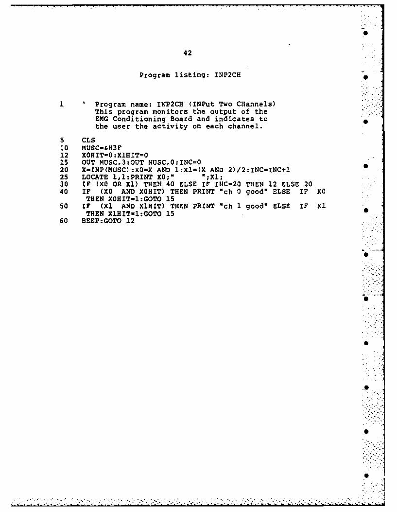
Program listing: INP2CH
1 'Program name: INP2CH (INPut Two CHannels)This program monitors the output of the --
EMG Conditioning Board and indicates tothe user the activity on each channel.
5 CLS10 MUSC=&H3F12 XOHIT-O:X1HIT=O15 OUT MUSC,3:OUT MUSC,0:INC=020 X=INP(MUSC):XO=X AND l:X1=(X AND 2)/2:INC=INC+l25 LOCATE l,l:PRINT XO;" ;l30 IF (XO OR Xl) THEN 40 ELSE IF INC=20 THEN 12 ELSE 2040 IF (XO AND XOHIT) THEN PRINT "ch 0 good" ELSE IF XO
THEN XOHIT-l:GOTO 1550 IF (Xl AND XlHIT) THEN PRINT 'ch 1 good" ELSE IF XI
THEN X1HITl1:GOTO 1560 BEEP:GOTO 12
41
Program listing: SPK-WORD* 6
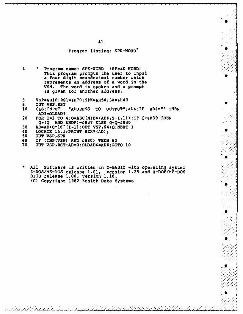
1 ' Program name: SPK-WORD (SPeaK WORD)This program prompts the user to inputa four digit hexadecimal number whichrepresents an address of a word in theVSM. The word is spoken and a promptis given for another address.
3 VSP-&HIF: RST-&H70 :SPK=&HSO :LA-&H405 OUT VSP,RST10 CLS:INPUT wADDRESS TO OUTPUTO;AD$:IF AD$-"" THEN
AD$-OLDAD$20 FOR 1-1 TO 4:Q-ASC(MID$(AD$,5-II)):IF Q>&H39 THEN
Q-(Q AND &HDF)-&H37 ELSE Q=Q-&H3030 AD-AD+Q*16^(I-l):OUT VSP,64+Q:NEXT I40 LOCATE 15,1:PRINT HEX$(AD);50 OUT VSP,SPK60 IF (INP(VSP) AND &H80) THEN 6070 OUT VSP,RST:AD-O:OLDAD$-AD$:GOTO 10
• All Software is written in Z-BASIC with operating systemZ-DOS/MS-DOS release 1.01, version 1.25 and Z-DOS/MS-DOSBIOS release 1.00, version 1.10.(C) Copyright 1982 Zenith Data Systems
. ... ..
39
The system can also be improved by making it more S
interactive with the user. For example, the user may be
given the option to change the limit of the counter used in - -
the E 1G input algorithm. Another option could change the
threshold value of the comparator on the EMG conditioning
board. This type of interaction would allow the user to
fine tune the system to provide maximum performance for a
variety of conditions.
S.i
. . ... -
.w . -. -
CHAPTER VII
CONCLUSIONS AND RECOMMENDATIONS 6
Summary
The final working system shows the capability of using 0
myoelectric signals to control a computer. This serves as a
direct link between the human operator and the computer.
Using this link, systems can be developed which capitalize
on the strengths of both human intelligence and computer
efficiency.
Recommendations
-The myoelectric control system will need to be upgraded
for operation in a G force environment. This section 0
discusses a few suggestions to improve the overall operation
the the system.
A parallel coding technique using signals from many
groups of muscles will probably be necessary. In addition,
tbis parallel coding should use muscle groups which are .
unrelated. This combination will decrease the chances of a r-
natural or reflex movement being recognized as a input. For -
example, blinking one eye would be more advantagious than .
blinking both eyes because blinking both eyes is a reflex. -
38
... -..

p S
37
Left I Right II Effect S
a I 0 II None0 I 1 II Scan1 1 0 II Select1 I 1 II First Arrival
Table 2. Coding for Demonstration
This test has been run on different people a number of
times. The outcome of all tests has been favorable. In
each case, the operator was able to maintain control over
both the Pong game and the myoelectric control system. To
test for possible noise effect on the system, the operator
was told to do nothing. The system was running for over a
half hour under these conditions with no spurious input
recognized. In addition, the operator can make slow easy
movements without having the system react.
I 0.. *".*. .
36
a ca
C
CHAPTER VI
EXPERIMENTATION
The experiments described here are done to test two
aspects of the myoelectric control system. First, an
experiment is performed to show that the user could control
the computer's operation without error. The second test is
to show that the user can be performing another task at thei -
same time. Both these tests are satisfied by the
demonstration outlined here.
A visual look at the test conditions is shown in figure
20. The user is hooked up to the myoelectric control system
and also holds the controls to a simple Pong game. The
object of the test is to operate the Pong game to the best
of the user's ability and still be able to control the
myoelectric control system. During the test, the user is
told what function the computer is to perform. The user
must then be able to get the computer to react in the
desired manner without missing a shot in the pong game. The
coding of the system is shown in 'Table 2.
35
I"0
34
These functions are also enhanced by the computer's
ability to act as an expert system. For example, the MENUS
program can detect errors in the required sequence to fire
an armament and inform the user of his mistake. This
program also remembers which armaments were fired and
removes them from the menu.
The computer can also monitor other input devices which
could aid in the operation of the entire system. This
activity is simulated by the MENUS program with the
subroutine to provide radar feedback. This subroutine could
be replaced by a system to monitor the actual radar. The S
computer can then use this input to assist the pilot.
S-
S
* S.
* -"°
33
EMG INPU
E:11G
-[AGOR
ALGORITH
DEACTIVAT
CURN
Figure 19. Menu Sca Flowhar
I ME
48
U
9 S
c
VVV"V
49
on bS
C40
lb q I
I' ~ ~ 0ii~ - .uUZZ44'~ ~ A
_ _ _ _ __w c 0
04 C-4
40
404
AJ~
VA 1
*q -c v~~~..' - -- q n ~~
°*._
*1 0
BIBLIOGRAPHY
1. Brody, G., Balasubramanian, R., and Scott, R. N., "AModel for Myoelectric Signal Generation," MedicalAnjd R jjagica Engineering, January 1974, pp. 29-41.
2. Doerschuk, P. C., Gustafson, D. E., and Willsky, A. S."Upper Extremity Limb Function Discrimination,"I=EE Transactions Bn c Engineering. k, 0Vol. 30, No. 1, January 1983, pp. 18-27.
3. Libes, Sol, and Garetz, Mark. interfacina t2 S-100/IEEE 696 microcomputers. Berkeley, California:Osborne/McGraw-Hill, 1981
4. Millman, Jacob. Microelectronics- Digital Aad AnalogCircijita And Sytems. New York: McGraw-Hill, Inc,1979
5. Petrofsky, J. S. "Computer Analysis of the Surface EMGDuring Isometric Exercise," St. Louis, Missouri. 5
6. Petrofsky, J. S. "Frequency and Amplitude Analysis ofthe EMG During Exercise on the Bicycle Ergometer,"St. Louis, Missouri.
7. Petrofsky, J. S. "On-line Analysis of the FatigueInduced in Muscle During Isometric Exercise," St.Louis, Missouri.
8. Rogers, D. B., "Myoelectric Feedback Control ofAcceleration Induced Visual Scene Dimming inAircraft Training Simulators." Ph.D. dissertation, 0University of Dayton, 1978.
9. Linear aaA Book, Fairchild Camera and InstrumentCorporation, 1982
10. NReview and Analysis of Literature Relating to •Neurobiological Coupling (Sensorimotor Control of --
Selected Devices through MicroprocessorInterface)", Technical Report Submitted to theUnited States Air Force, Dept. of Physiology andBiophysics, New York University Medical Center, 550First Avenue, New York, NY
so
. . . . ..... .
51
11. =L Dat B22k, Fairchild Camera and InstrumentCorporation, 1978
12. 2-100~g Seie J~~ Manu~ial, Zenith Data Systems, 1982
13. 7-nns, Vols. 1-2, Zenith Data Systems, 1982%
14. jjgja Z-BASILC (Z-DaL, Vols. 1-2, Zenith DataSystems, 1982
15. ZJ100 Aeris Technical Mtanua~l (adware), Zenith DataSystems, 1983
0

FILMED
7-85
DTIC