menards hb part 1 of 2 - menards® - dedicated to service...
TRANSCRIPT
INSTALLATION INSTRUCTIONS HORSE BARN
Our unique assembly process quickly transforms the individual pieces into a finished structure that will give you a lifetime of service. Great care has been taken to ensure complete satisfaction with your purchase. In the unlikely event that there are any missing or damaged parts or if you simply need technical assistance, please call our Toll Free Hot-line at 1-800-900-7222 and your questions will be addressed promptly. Thank you for choosing the Versatube Building System.
PAGE 1 © Mid-South Metal products, Inc. 2-12-03

SAFETY AND HAZARD INSTRUCTIONS
CAUTION: Read the following safety warnings and all instructions in their entirety prior to installation. If you have questions or are missing any parts, contact Mid-South Metal Products, Inc. (DBA, VersaTube Building systems) customer service at 1-800-900-7222 before proceeding. WARNING: Metal parts may get hot when exposed to high heat or direct sunlight. Avoid contact with skin and wear protective gloves and clothing to prevent the possibility of burns. WARNING: Standing or walking on the structure could cause damage to the sheet metal panels. If you must walk on the roof, step within 1’ of a major frame member on flat sections, not on major ribs. The structure must be properly braced to support human weight. Collapse of the structure may cause serious injury do to weight of components. WARNING: Avoid installation on windy days as wind may create hazards during the installation process. Wind may blow material or cause partially installed components to collapse prior to being secured or fully installed. The weight of the components or structure may cause serious injury if it should collapse. WARNING: Metal conducts electricity and electrical shock hazards exist since the structure is made of metal. During installation or storage, keep the structure and all components away from electrical sources. Make sure that your selected location is away from power lines, underground cables, and any other source of electrical power. Serious injury or even death may occur if contact is made with electrical current. WARNING: In the event that your structure is fully enclosed, be sure to provide proper and adequate ventilation. Hazardous, poisonous or noxious substances should not be stored in the structures absent proper ventila-tion. Follow all warnings and instructions of the manufacturer of any substance stored in your building. Also, proper ingress and egress should be provided to prevent persons or children from Becoming trapped inside the structure. WARNING: If metal panels are selected to cover all or a portion of your structure, be careful of the sharp edges which may cause cuts or lacerations. Wear protective work gloves and suitable clothing for protection and always take care when handling metal parts. Wear safety glasses when installing self-drilling screws or holding parts for someone who is installing screws. NOTE: Metal buildings can sweat in cold weather, barns in particular because of moisture in the exposed soil. If the moisture inside the barn is high and the temperature outside the barn is cold, condensation can form on the inside of the metal walls and roof. This can be reduced by creating more ventilation or insolating the barn.
PAGE 2 © MSMP INC. 1-29-03

ATTENTION: IT IS IMPORTANT THAT YOU READ THE FOLLOWING NOTES
BEFORE STARTING THE ASSEMBLY OF YOUR BARN
NOTE: If you are not mounting the barn to a level concrete footing or curb , you should level the selected area and remove high spots caused by roots or rocks. It is particularly important that the areas on which the barn base rail assemblies will sit are level with each other. Choose a level site away from power lines. Concrete footings are recommended. NOTE: If during the installation process you have Difficulty fitting frame components together, use an adjustable wrench to open end of receiving tube as shown at right. Close wrench down around bent portion of tube and bend wall outward.
What you’ll need: 2 Step Ladders
Work Gloves
Level
Shovel or Post Hole Digger
Tin Snips
Tape Measure
Hammer
Pencil/Marker
Cordless (14 or 18 volt) Or Electric Drill With 5/16" Socket Drive
PAGE 3 Saw of your choice to cross cut and rip lumber for stalls
Chalk Line and Mason Line
One must be able to Comfortably reach the peak of the barn 16' high.
© MSMP INC. 1-29-03
1/2” x 12” Masonry Drill Bit
Hammer Drill 1/2” chuck

PARTS LIST FOR MAIN FRAME SECTION (HB2-3612-M) AND PURLIN / GIRT KIT (HB-36-PG)
QTY. PART DESCRIPTION PART # LETTER
4 STARTER BASE RAIL (2 PINS, NO SWAGED END) 71-4602 A
4 6’ LENGTH EXTENSION BASE RAIL (1 PIN) 71-7040 B
6 SIDE POST 71-5008 C
6 5’ HEIGHT EXTENSION HE-5 D
3 PEAK 71-6000 E
6 RAFTER 71-2000 F
6 LEAN-TO RAFTER 71-8500 G
6 LEAN-TO BRACKETS BK-50 H
12 CORNER BRACKETS BK-40 I
12 1” SELF-DRILLING SCREWS (HEX HEAD) 70 PACK 71-9999 J
140 PAN HEAD, SQUARE DRIVE, SELF-DRILLING SCREWS 71-9999-PAN J1
4 LOWER GIRT 2 X 3 X 69 3/4” 7100-6975 K
40 UPPER SIDE GIRT / ROOF PURLIN 1 1/2” SQUARE X 69 3/4” 7500-06975 L
8 ANGLE BRACKET BK-10 N
40 SINGLE PURLIN BRACKET BK-30 M
12 DOUBLE PURLIN BRACKET BK-31 M2
8 DOUBLE PURLIN BRACKET (WIDE) BK-31W M3
A
B
C
I
G
I F
E
C
D A
B
H
PAGE 4
J CORNER BRACKET (I) AS SHIPPED
FOLDED
M
M3 M2
J1 I
H
© MSMP INC. 1-29-03
#2 Square Driver
K
N
K

NOTE: IF THE BARN FRAME THAT YOU HAVE PURCHASED DOSE NOT INCLUDE THE VERSATUBE STALL SYSTEM, YOU WILL BE INSTALLING LOWER AND UPPER GIRTS ON THE SIDES OF THE BARN. IF YOU HAVE PURCHASED THE VERSATUBE STALL SYSTEM, NO LOWER GIRTS ARE NECESSARY ON THE BARN SIDES WHERE STALLS ARE INSTALLED.
PARTS LIST FOR 12' BARN EXTENSION (HB-36-LE) & (HB-36-LE-PG)
THIS LIST INCLUDES THE PARTS YOU WILL NEED TO EXTEND THE MAIN FRAME 12'.
QTY. PART DESCRIPTION PART # LETTER
4 6’ LENGTH EXTENSION BASE RAIL (1 PIN) 71-7040 B
2 PEAK 71-6000 E
4 RAFTER 71-2000 F
4 LEAN-TO RAFTER 71-8500 G
4 5’ HEIGHT EXTENSION HE-5 D
4 LEAN-TO BRACKET BK-50 H
8 CORNER BRACKET BK-40 I
9 1” SELF-DRILLING SCREW (HEX HEAD) 70 PC. 71-9999 J
68 PAN HEAD, SQUARE DRIVE, SELF-DRILLING SCREWS 71-9999-PAN J1
4 LOWER GIRT 2 X 3 X 69 3/4” 7100-6975 K
40 UPPER SIDE GIRT / ROOF PURLIN 1 1/2” SQUARE X 69 3/4” 7500-06975 L
8 ANGLE BRACKET BK-10 N
28 DOUBLE PURLIN BRACKET BK-31 M2
16 DOUBLE PURLIN BRACKET, (WIDE) BK-31W M3
NOTE: BARN EXTENSIONS ARE 12’ IN LENGTH. THE MAIN (STARTER) SECTION IS 12’-2” LONG. STALLS FIT A 12’ SECTION. THE LENGTH OF YOUR BARN WILL BE DETERMINED BY THE NUMBER OF 12’ LENGTH EXTEN-SIONS THAT YOU ADD. (YOU WILL NEED PURLINS AND GIRTS FOR EACH SECTION) NOTE: THE (HB2-LE-PG) FOR BARNS WITH VERSATUBE STALLS WILL NOT HAVE LOWER GIRTS (K) OR ANGLE BRACKETS (N).
H
B
B
C
I
G L
K
I F E
C
N
H
I
M2
J M3
PAGE 5
D
© MSMP INC. 1-29-03

PARTS LIST FOR FRONT AND BACK ENCLOSURES WITH GIRTS (HB-36-FE) (HB-36-BE) (HB-36-FE-PG)
(HB-36-BE-PG)
QTY. PART DESCRIPTION PART # LETTER 4 DOOR TRACK BACKERS 2 X 3 X 69.25” 7100-6925 Q
2 DOOR HEADERS 2 X 3 X 137 7/8” 7100-1378 R
1 DOOR HEADER BRACE 2 X 2 X 68 1/2” 7400-6850 S
4 FRONT AND BACK BASE RAIL 2” SQ., 1 PIN 74-4601 T
4 FRONT AND BACK LEAN-TO VERTICALS 2” SQ. X 103” 7400-10300 U
2 T-CONNECTOR 71-BE-T V
2 BACK, CENTER UPRIGHT 2 X 2 X 81 3/4” SWAGED ONE END 74-8175 W
2 BASE RAILS 2 X 2 X 34 1/2” 7400-3450 X
1 BASE RAIL 2 X 2 X 24 1/2” 7400-2450 Y
2 BACK UPRIGHT EXTENSION 2 X 2 X 79 5/8” 7400-7962 Z
9 BACK CENTER GIRTS 1 1/2” SQUARE X 44 3/8” 7500-04437 L1
8 LOWER GIRT (BACK & FRONT LEAN-TO SEC.) 2 X 2 X 69 3/4” 7400-6975 K1
8 UPPER GIRT (BACK & FRONT LEAN-TO SEC) 1 1/2 SQ. X 69 3/4” 7500-06975 L2
2 ABOVE DOOR GIRTS 1 1/2 SQ. X 67 3/4” 7500-06775 L3
16 SINGLE PURLIN BRACKET BK-30 M
11 DOUBLE PURLIN BRACKET BK-31 M2
20 FLAT BRACKET BK-20 O
39 ANGLE BRACKETS BK-10 N
10 1” SELF-DRILLING SCREWS (HEX HEAD) 70 PACK 71-9999 J
50 PAN HEAD, SQUARE DRIVE, SELF-DRILLING SCREWS 71-9999-PAN J1
Q
K1 T
L2
L3 S
R
UX
L1
T K1
L2
Y
U
Z
W PAGE 6
N M2
M
J J1
V
O
#2 Square Driver
© MSMP INC. 1-29-03
L2

STEP 1: PREPARING THE FOUNDATION After you have chosen a site for your barn, carefully prepare the site so it is level 6’ beyond the building on all sides. The barn may be anchored in several ways: It may be placed on a concrete slab. It may be anchored on a concrete curb with piers or footing, or it may be anchored directly on the level ground with ground anchors set in concrete. A– If you will be poring a concrete slab the slab should be at least 4” thick with a 12” wide x 12” deep (or 1’ below frost line) footing around the parameter and down both sides of the center isle. The outside dimensions of the barn: The main barn unit is 36’-2” wide and 12’-2 1/2” long from outside of base rail to outside of base rail. Extensions to the main section are 12’ long. Base rails will be anchored to the concrete slab with 1/2” x 7” concrete anchor bolts (wedge anchors). B– If you will be anchoring your barn to concrete curbs, see the layout below. The piers should be 12” in diameter and 12” deep (or 12” below frost line) every 6’. Layout all piers and pour them first. Place a piece of rebar vertically and cen-tered in each pier extending above the top of the pier 3”. Piers should be level with each other. You may find that a 12” diameter concrete form (available at your building supply store) will help in leveling and pouring piers. POURING THE CURBS: Use 2 x 6 lumber to create forms for curbs. Install (2) #4 rebar rods down the length of each curb at mid-depth. (See detail on next page) Do not place the rebar in the center of the curb where concrete anchor bolts will be installed. Pour concrete level with top of forms. When concrete sets and forms are removed, backfill dirt to within 2” of the top of the curbs on the outside of the building and to within 3 to 4” of the top of the curb in the stalls. Note: the layout below is for a 36”-2” x 36’-2” barn frame. Add or subtract sections in 12’ increments.
IMPORTANT NOTE BEFORE YOU START ASSEMBLY OF THE BARN: (1) WE SUGGEST YOU CHECK WITH YOUR LOCAL BUILDING OFFICIAL REGARDING SITE LOCATION, PERMIT PROCEDURES, SAFETY REGULATIONS AND SPECIFICATIONS OF MATERIALS USED TO CONSTRUCT YOUR NEW BARN. (2)- IF SHEET METAL PANELS ARE NOT BEING USED IMMEDIATELY, STORE THEM IN A DRY AREA OUT OF THE SUN. (3)- BEFORE THE BUILDING IS DELIVERED MAKE SURE THAT YOUR SITE IS CLEAR. PREPARE THE SITE SO IT IS LEVEL 6’ BEYOND THE BUILDING ON ALL SIDES. REMEMBER TO MAKE SURE THERE IS ENOUGH ROOM FOR THE DELIVERY TRUCK TO MOVE AROUND YOUR SITE. THE BIGGER THE BUILDING ,THE BIGGER THE TRUCK DELIVERING THE BUILDING WILL BE.
ASSEMBLY INSTRUCTIONS
PAGE 7
DETAIL OF CURB AND PIER
CURB
PIER
LAYOUT SHOWN IS FOR 36”-2” X 36’-2” BARN.
GRADE
OR REQUIRED
DEPTH
6"
6" 6"
6"
6"
BACK FRONT
FOR ENCLOSED BACK CENTER ISLE, EXTEND
CENTER ISLE
6"
© MSMP INC. 2-3-03
12” Ø
72” TYPICAL
145”
141”
145”
12”
12”
5 1/2”
BARN EXTENSIONS ARE 12’.

C- If you choose to poor concrete footings for the exterior walls and down the center isle, see the drawings below for the footing layout and section. NOTE: The depth of the footing should be 12” or 12” below frost line. The divider walls can sit on concrete curbs 6” wide and 5 1/2” high. Install two pieces of #4 rebar down the length of each curb. (The rebar must not be placed in the center of the curb where concrete anchor bolts will be installed.) When concrete is set and forms are removed, backfill dirt to within 2” of the top of the footing on the outside of the building and to within 3” to 4” of the top of the footing/curb in the stalls.
PAGE 8
BACK
IF YOU WILL BE ENCLOSING THE BACK OF THE CENTER ISLE, EXTEND THE FOOTER ACROSS THIS SPACE.
FOOTING AND CURB LAYOUT
CURB FOOTING
FRONT
SIDE
SIDE
CENTER ISLE NOTE: ALL DIMENSIONS EXCEPT 6” CURB WITH ARE CENTER LINE DIMENSIONS
6"
12"
GRADE
5 1/2"
12” OR 12” BELOW FROST LINE
FOOTING SECTION FOR CENTER ISLE AND OUTSIDE WALLS
CURBS RUN FROM CENTER ISLE FOOTER TO FOOTER AT OUTSIDE OF BUILDING. THE CURBS PROVIDE A SUPPORT AND ANCHOR POINT FOR STALL DEVIDER WALLS.
CURB SECTION
6"
5 1/2"
GRADE
#4 REBAR, MID DEPTH
© MSMP INC. 2-3-03
#4 REBAR, MID DEPTH

STEP 2: ASSEMBLING BASE RAILS Find the Base Rails with 2 pins welded to them. These are the starter Base Rails (A). Place these base rails at the front of the building. Every additional Base Rail will be a 6’ Length Extension Base Rail (B). Base Rails (B) will have a swaged end. Place the 4 Starter Base Rails (B) at the front of the building. The center isle base rails will be 12’ outside to outside. The lean-to section base rails at the outside of the building will be 145” from the outside of the center section base rails to the outside of the lean-to base rails. The outside dimension of the barn is 36’-2”. Now, insert the 6’ Extension Base Rails (B) into the Starter Base Rails (A). The number of base rails inserted will deter-mine the length of the building. Example: a 36’-2” long building will have 1 starter base rail and 5 extension base rails from the front to the back of the building. The illustration below shows a 36’-2” x 36’-2” building. Note: the pins on the base rails are on 6’ centers. The inside distance from one pin to the next must be carefully set at 70”. Measure and set the base rails to the dimensions shown below. Take a diagonal measurement on each 12’ section to be sure the base rails are square. The diagonal measurements should be equal. HINT: It may be helpful to snap chalk lines to use as a guide to keep base rails square and straight. Fasten the base rails together with (1) 1” self– drilling screws (J) on the inside, top edge of each joint. Anchor each base rail with concrete anchor bolts or 30” concrete ground anchors depending on your foundation.
PAGE 9
STARTER BASE RAIL (A)
6’ EXTENSION BASE RAIL (B)
(B)
70”
70”
70” BETWEEN PINS
12’
12’-1”
DIAGONAL MEASUREMENTS SHOULD BE EQUAL
12’-1”
36’-2” OUTSIDE TO OUTSIDE
BASE RAIL ASSEMBLY
(A)
1/2”
1”
SCREW LOCATION DETAIL Place one self-drilling screw 1” from the pin and 1/2” from the inside edge of the base rail.
© MSMP INC. 2-3-03
OUTSIDE TO OUTSIDE OF CENTER ISLE RAILS

If you will be anchoring the base rails to the ground, you will need to layout the base rails for the center isle and lean-to sections, mark on the ground the locations of the anchor holes, slide the base rails to one side and dig 1’ wide x 2’ deep holes at each anchor location. Now, reposition the base rails over the holes, recheck all dimensions and drop a 30” ground anchor through each anchor hole in the base rails. Tap the anchors down with a hammer and poor concrete in each anchor hole up to grade. Recheck all dimensions wile the concrete is still soft. Let the concrete set before attaching frame sections. If you are anchoring the base rails to a concrete slab or curbs, place base rails on slab, square and set dimensions as shown on page 9 and anchor base rails to concrete with 1/2” x 7” concrete anchor bolts (wedge anchors) and flat washers.
CONCRETE
30” GROUND ANCHOR
24”
FLAT WASHER
DRILLED HOLE CONCRETE
BASE RAIL
ANCHOR BOLT DETAIL FOR SLAB OR CURB MOUNTING
ANCHOR BOLT
STEP 3: ANCHORING THE BASE RAILS
30” GROUND ANCHOR
STEP 4: ASSEMBLING THE CENTER ISLE ROOF/WALL SECTIONS
PAGE 10
HELPFUL HINT: Prior to starting step 4, it is helpful to align each peak so the slight dimple in the bend is to the same side. This will make the inside roof framing appear straight and even.
Slight dimples in tube should be on the same side of structure
© MSMP INC. 2-11-03
12”

ROOF/WALL SECTION ASSEMBLY Take one Side Post (C) and insert one Height Extension (D) on bottom and one rafter (F) on top as shown below. Repeat this assembly with another Side Post , Height Extension and Rafter. Now, Connect the two assemblies with one Peak (E). Measure 12 feet across the assembly from outside to outside toward the top and bottom of the Assembly. Try to keep the joint spacing equal on both sides of the assembly. Recheck the 12 foot outside dimensions and fasten each joint with two #12 x 1” Self-Drilling Screws (J). (See illustration below for screw locations.) Place the Roof/Wall section assembly on the Base Rail assembly (center isle rails) to check the fit. Make any necessary adjustments. (this may require reattaching of joints on the Roof/Wall section assembly). Make equal adjustments on both sides of the assembly. When the assembly fits properly, lay it back on the ground and use it as a template or guide for assembling the remaining Roof/Wall sections.
D
D SELF-DRILLING SCREW (J)
C
F
E
F
C
CORNER BRACKET (I) LOCATION
ROOF/WALL SECTION
STEP 6: ATTACHING ROOF/WALL SECTIONS TO BASE RAILS
NOTE: this step will take two people to complete safely and easily. Lift and place the legs of each as-sembly on the base rail pins. Fasten each joint with 2 self-drilling screws (J). Do not place the screws on the outside of the building where sheet metal will be attached.
CENTER ISLE BASE RAILS
12’ SECTION ONLY SHOWN
PAGE 11 © MSMP INC. 3-11-03
12'
12'
TYPICAL JOINT, SIDE POST TO RAFTER AND RAFTER TO PEAK
HEIGHT EXTENSION TO SIDE POST (2 SCREWS)

STEP 6: ASSEMBLY OF LEAN-TO SECTIONS Connect one Side Post (C) with one Lean-to Rafter (G) and one Lean-to Bracket (H). Do not fasten the Lean-to Bracket joint at this time. Fasten the connecting joint of the side post and rafter with two 1” Self-Drilling screws. Put a mark on all side posts of the center section frame 122 1/4” up from the bottom of the base rail. This will be the location of the bottom of the Lean-to Bracket when you attach the Lean-to assembly to the center frame. Now, put the assembly in place on the barn as shown with the side post (C) on the first pin of the (lean-to) base rail (A) and the Lean-to Bracket (H) on the center isle frame side post. The bottom of the Lean-to Bracket should match up with the line you marked on the center isle frame side post. (Note that the joint of the lean-to rafter and the lean-to bracket are is not yet fastened) Clamp or install one screw in the lean-to bracket to attach it to the center isle frame. Measure the dis-tance from the outside of the center isle frame to the outside of the lean-to section side post at the top and set the dimension at 145”. Fasten the joint of the lean-to bracket (H) and the Lean-to rafter (G) with the dimension set at 145”, with two 1” self-drilling screws (J). This assembly should be plumb. Check the center isle frame for plumb and the lean-to section for plumb. Make any adjustments necessary to make all components plumb. Now, remove the screw or clamp used to fasten the lean-to bracket to the center isle frame. Remove the assembly from the base rail and use the assembly as a template for the remaining lean-to section assemblies. Assemble the remaining lean-to sections and install them to the barn. If you will be installing the Versatube Stall system, do not place any screws in the joint of the lean-to side post to the base rail pin at this time. If you will not be installing the Versatube Stall System, fasten each joint with two 1” self-drilling screws at this time. (do not place the screws on the outside of the building where sheet metal panels will be installed.)
122 1/4”
MARK
LEAN-TO BRACKET (H)
LEAN-TO RAFTER (G)
LEAN-TO SIDE POST (C)
145”
NO SCREWS IN THESE JOINTS IF YOU WILL BE INSTALLING THE VERSATUBE STALL SYSTEM.
FASTEN THIS JOINT WITH 2 SCREWS
DO NOT FASTEN THIS JOINT WITH SCREWS UNTIL MEASUREMENTS ARE SET.
PAGE 12
#12 X 1” SELF-DRILLING SCREW (J)
© MSMP INC. 4/01

STEP 7: BACK ENCLOSURE ASSEMBLY, HB-36-BE & HB2-36-BE THESE ASSEMBLY INSTRUCTIONS ARE FOR BOTH THE (HB-36-12, BARN WITHOUT STALL SYSTEM) AND THE (HB2-3612, BARN WITH STALL SYSTEM). IF YOU WILL NOT BE INSTALLING THE VERSATUBE STALL SYSTEM, YOU WILL INSTALL UPPER AND LOWER GIRTS IN THE LEAN-TO SECTIONS OF THE BARN. IF YOU WILL BE INSTALLING THE VERSATUBE STALL SYSTEM, NO UPPER OR LOWER GIRTS WILL BE INSTALLED IN THE LEAN-TO SECTIONS. SEE PAGE 6 FOR PARTS LIST FOR FRONT AND BACK ENCLOSURES.
BASE RAIL ASSEMBLY: In the Lean-to sections of the barn, (back wall), place 1 Front/Back Base Rail (T) 2” square, 142” long with 1 pin welded in the center. Fasten the Base Rail at both ends to the barn outside base rail and to the cen-ter isle base rail with Angle Brackets (N) and 1” self-drilling screws (J). Anchor the center of the Base Rail with a concrete anchor bolt as you did the other base rails. Now, if you will not be installing a door at the back of the barn, assemble 2 T-Sections (V), 1 Center Base Rail (Y), and 2 Base Rails (X) as shown between the center isle base rails at the back of the barn (do not fasten the joints with screws at this time. If the base rails are not being anchored to a concrete slab or curb mark the location of the T-Section holes on the ground, remove the base rail assembly and dig anchor holes as you did for the other base rails. Replace the base rail assembly and attach the end base rails (X) to the center isle base rails with Angle Brackets (N) and Self-Drilling Screws (J). Measure and set the distance from the center isle base rail (inside) to the outside of the T-Section vertical pin at 44 5/8”. Do this for both T– Sections (V). Center the center base rail (Y) and fasten all the joints with two 1” Self-Drilling Screws (J) at this time. (Place the screws on the top of the base rails.) Now, anchor the T-Sections (V) to the curb, slab, or ground as you did the other base rails. (Make sure the base rail assembly is straight before anchoring.)
44 5/8” (V)
(Y)
(X)
(T)
(N) Typical 6 places
(T)
JOINT DETAIL
INSTALLING BACK VERTICALS: In the lean-to sections of the barn install Back Vertical Tubes (U) 2 x 2 x 103” long, on the base rail pins. Make sure that the verticals are plumb and fasten them on the inside of the rafter with a Flat Bracket (O) and 1” Self-Drilling Screws (J). If you are not installing the Versatube Stall System, at-tach the verticals at the bottom with 1” Self-Drilling Screws (J) at this time. Place the screws on the side of the tube joint. If you are going to install the Versatube Stall System, the joint will be fastened when you install the vertical channels. In the center/back section of the barn you will install an assembled back vertical in two places on the T-Section pins. To create the back center vertical join one Back Center Upright (W) and one Back Upright Extension (Z). Plumb the verticals and fasten to the rafters on the inside of the building with Flat Brackets (O) and 1” self-drilling screws (J).
(U)
(U)
(W)
(Z)
FLAT BRACKET JOINT DETAIL
(O)
PAGE 13
See parts list on page 6 for part description
BACK FRAME OF BARN
© MSMP INC. 4/01

STEP 8: INSTALLING BACK GIRTS
NOTE: If you will be installing the Versatube Stall System, you will not install upper or lower girts in the lean-to sections. Install the 9 girts in the center isle section first. These girts are 1 1/2” square tube 44 3/8” long (L1). Install the girts as shown below at the heights specified and with the purlin brackets indicated in the illustration below. If you will not be installing the Versatube Stall System, install Upper girts (L2) and Lower Girts (K1) in lean-to sections as shown below. Use Angle Brackets (N) to attach lower girts in lean-to sections.
DOUBLE PURLIN BRACKET (M2)
SINGLE PURLIN BRACKET (M)
(M)
(M)
(M2)
(M2)
ANGLE BRACKET (N)
(N)
(N)
(M2)
(M) 48”
LOWER GIRT (K1)
FROM BOTTOM OF BASE RAIL TO TOP OF GIRT
36 1/2”
36 1/2”
(L2)
IMPORTANT: Check the frame for plumb before you attach girts to brackets. Keep checking frame for plumb as you go along.
PAGE 14
PAN HEAD SCREWS ON OUTSIDE OF BARN (J1)
(J)
(J) (J)
(M2)
(M)
OVERLAP SINGLE PURLIN BRACKETS
SINGLE PURLIN BRACKET DETAIL
DOUBLE PURLIN BRACKET DETAIL
LOWER GIRT DETAIL ANGLE BRACKET (N)
(J1)
(J)
(M)
(J)
(N)
(L1) 9 PLACES
© MSMP INC. 4/01
#10 x 7/8” Square Drive Self-Drilling Screw (J1) and #2 Square Driver
#12 x 1” Self-Drilling Screw

STEP 9: FRONT ENCLOSURE ASSEMBLY INSTALLING THE LEAN-TO SECTION BASE RAILS. Place a Front/Back Base Rail (T) between the center isle and outside base rails in both lean-to sections at the front of the barn (2 places). Fasten both ends of the base rails (T) to the center isle and outside base rails with Angle Brackets (N) and 1” Self-Drilling Screws (J). Note: If you will be installing the Versatube Stall System, the angle brackets must be installed on the inside corners so they do not interfere with the installation of Stall Panel Vertical Channels on the side posts. (See detail below) If you will not be installing the Versatube Stall System, you can mount the angle brackets on the top of the base rail. Anchor the base rail through the hole near the pin as you did the other base rails. (Ground Anchor or Concrete anchor bolt)
(T)
(T)
(J)
ANCHOR HOLE
Now, install the Center Uprights (W). Place the uprights on the base rail pins, plumb the uprights, and fasten them to the rafter above with a Flat Bracket (O) and Self-drilling screws (J) on the inside of the barn. (See detail)
PLACE BRACKET ON INSIDE OF BARN
(J)
(O)
(W)
(W) PIN
PIN
PAGE 15 © MSMP INC. 4/01

INSTALLATION OF FRONT ENCLOSURE CONTINUED INSTALLING THE DOOR HEADER TUBES AND DOOR TRACK BACKER TUBES: Install the 1 Door Header Tube (R) at a height of 8’. Fasten the header tube to the barn frame with angle brackets (N) on the bottom side. (Make sure that the header is level and that the 3” surface faces forward) Now, place another Header Tube (R) 1” above the first header tube and fasten it on top at both ends with Angle Brackets (N). On the back of the header tubes attach 2 Flat brackets (O) to tie the header tubes together 45” from the ends. (See detail) Fasten an additional Flat Bracket (O) at both ends of both header tubes. (See detail). Now, attach the Door Track Backer Tubes (Q) in the lean-to sections. Lined up the top Backer tube flush with the Top Header Tube and the bottom Backer Tube 1” below the bottom Header tube. (there should be a 2” space between the top and bottom backer tubes) Fasten these tubes at both ends as you did the header tubes. (No center brackets are re-quired)
(R) (N)
(N)
(N)
(N)
(O)
(R) (Q)
(Q)
(Q)
(Q) (R)
(O) (N) (N)
(O)
DETAIL OF JOINT, HEADER TUBES (R) AND DOOR TRACK BACKER TUBES (Q)TO FRAME POST
FRAME POST
DETAIL OF HEADER ASSEMBLY FROM INSIDE BARN
(R) HEADER TUBES 2 1/4" APART
DETAIL OF DOOR TRACK BACKER TUBES (Q) TO LEAN-TO VERTICAL (W)
(N)
(N)
(O)
USE SELF-DRILLING SCREWS (J) TO ATTACH ALL BRACKETS
PAGE 16
VIEW FROM INSIDE OF BARN
© MSMP INC. 1-10-03
8'
(Q)
1"
CENTER HOLES NOT USED
2" (W)
(W)
45"
45"
1"
4 PLACES
(Q)
2"

INSTALLATION OF DOOR HEADER VERTICAL BRACE AND FRONT GIRTS
DOOR HEADER VERTICAL BRACE: Note: the Vertical Header Brace (S) comes from the factory 68 1/2” long to allow for different header assemblies. You will need to cut the Vertical Header Brace to 66 1/4” long for the assembly shown. (This assembly is for a rounded barn door track with flush mount brackets.) Place a Door Header Vertical Brace (S) on top of the top Door Header (R) centered in the frame center isle space. Fas-ten the bottom of the Door Header brace to the Door Header with a Angle Bracket (N) and Self-Drilling Screws (J). Fas-ten the top of the Door Header Brace to the Peak (E) with a Flat Bracket (O) and Self-Drilling screws (J) on the inside of the barn. (See illustrations) INSTALLING GIRTS: Install the Above Door Girts (L3) as shown using Single Purlin Brackets (M) on the outside corners and a Double Purlin Bracket (M2) in the center. (See illustration for location dimension) Use Hex head screws (J) except on the outside sur-face of the barn in Single Purlin brackets (M). Use Pan head, square drive screws (J1) on outside of building. A square drive bit is provided with screws. (See detail.) Now, install the Upper Girts (L2) and the Lower Girts (K1) in the lean-to sections as shown. On the top girts use Single Purlin Brackets (M) on the outside ends and a Double Purlin Bracket (M2) in the center. Fasten the Lower Girts (K1) to the frame with Angle brackets (N) on the top or bottom side. (See detail)
(M2)
(J)
(N)
(J)
TYPICAL LOWER GIRT JOINT
TYPICAL PURLIN/GIRT WITH DOUBLE BRACKET JOINT
TYPICAL GIRT END JOINT
VERTICAL BRACE TO PEAK DETAIL ON INSIDE OF BARN
VERTICAL BRACE TO HEADER JOINT
USE #12 X 1” SELF-DRILLING SCREWS (J) WITH ALL BRACKETS
PAGE 17
(M)
(O)
(N)
(K1)
(S)
(L3)
(L2)
4 Places
4 Places
(J1)
(J)
(J1)
© MSMP INC. 4/01
#2 SQUARE DRIVER
TOP DOOR HEADER

STEP 10: INSTALLING CORNER BRACKETS Corner Brackets (I) are shipped to you unfolded. You must first fold all of the corner brackets as shown to fit the corners of the lean-to and center isle side posts. Place the corner brackets on each side post bent corner, square them with the flat roof and side portions of the side post and attach them with 8 Self-drilling screws (J) as illustrated.
4 SCREWS (J) ON BOTH SIDES OF POST
SIDE POST (C)
CORNER BRACKET (I) UNFOLDED
FOLDED
TYPICAL BRACKET LOCATIONS
(I)
(I) (I)
(I)
STEP 11: INSTALLING ROOF PURLINS AND SIDE GIRTS
The roof purlins and the upper side girts are the same part. (L) 1 1/2” square x 69 3/4” long. The purlin/girts will be attached to the frame with purlin brackets. Single Purlin Bracket (M), Double Purlin Bracket (M2), and Double Purlin Bracket WIDE (M3). Use Single Purlin Brackets (M) at the ends of the building (front and back). Fasten with Self-drilling screws (J) to the purlin and use Pan head Self-drilling screws (J1) to fasten the tongue to the building frame (see detail). Use Double Purlin Brackets (M3) when joining two purlin/girts over a Corner Bracket (I). (see detail) Use Double Purlin Brackets (M) at all other double purlin/girt joints. (see detail) Use Angle Brackets (N) to fasten Lower Girts (K) 2” x 3” x 69 3/4” long to frame. See the Purlin/Girt layout drawing for purlin and girt location and measurements.
SINGLE PURLIN BRACKET (M)
DOUBLE PURLIN BRACKET (M2)
DOUBLE PURLIN BRACKET WIDE (M3)
PAGE 18
(J)
ANGLE BRACKET (N)
© MSMP INC. 4/01

48"
94"
48"
48"
48"
34 1/2" 1"
2"
34 1/2"
1"
PURLIN/GIRT LAYOUT GUIDE
ALL PURLINS AND GIRTS, EXCEPT THE LOWER SIDE GIRTS, ARE THE SAME. 1 1/2” SQUARE X 69 3/4”
(K)
NOTE: LOWER SIDE GIRTS (K) ARE 2” X 3” X 69 3/4”. (IN FRONT SECTIONS ONLY.)
Attach the girts on the sides of the barn first. The frame sections should be 72” on center or 70” between posts. Plumb the frame sections and continue to check the measurement between posts as you install the purlins and girts. Hint: If you mark the bracket locations on the frame sections at both ends of the barn first, you can use a mason line or chalk line to mark all the bracket locations in the center of the building. This method will keep all of your purlins and girts looking straight and assure that the screws used to fasten the roof panels will always hit the purlins properly. The details below will show you the correct brackets to use at each purlin/frame joint.
TYPICAL JOINT FOR LOWER SIDE GIRTS. USE ANGLE BRACKET (N)
TYPICAL SINGLE PURLIN JOINT AT THE FRONT AND BACK OF THE BARN. USE SINGLE PURLIN BRACKET (M)
TYPICAL DOUBLE PURLIN JOINT. USE DOUBLE PURLIN BRACKET (M2)
TYPICAL CORNER JOINT USE DOUBLE PURLIN BRACKET (WIDE) (M3)
(N)
(M)
(M3)
(M2)
PAGE 19
(N)
(M)
(J1)
(J)
(J)
(M3) (J1)
(J)
(L)
(M2)
(J)
© MSMP INC. 2-11-03
#12 x 1” Self-Drilling Screw (J)
#10 x 7/8” Square Drive Screw (J1)
(K)
(K)

STEP 12: INSTALLATION OF DUTCH DOOR FRAME AND GIRTS
A Dutch door frame will be installed in every other section of your barn. STEP 1: Install two angle brackets (N) as shown at right with screws (J). Position the top surface of the bracket 48” from the bottom of the base rail. These brackets will be used to attach short girts on both sides of the door. STEP 2: Pre-attach three angle brackets (N) to each door jamb tube. One bracket at each end of the tube and one with the top surface of the bracket 46” from the bottom end of the tube. Note: You are creating a left and right door jamb, so position the brackets flush with what will be the inside of the door jamb when they are installed. The door jamb tubes are 2” x 4” x 87” long. STEP 3: Install the door frame top support (2” x 3” x 69 34”) as shown 87” from the bottom to the top of the base rail. The support tube is 1/4” shorter than the space between frame sections. You may want to measure and pre-attach the angle brackets to the barn frame. STEP 4: Attach the door jambs, header tube and short girts as shown below. Be sure that the door jambs are plumb and all tubes are flush with the inside of the barn frame. The door frame will hang out 1” beyond the barn frame. Check all measurements carefully.
46”
48”
87”
8 9/16”
8 9/16”
47 7/8”
DOOR FRAME TOP SUPPORT 2” X 3” X 69 3/4”
DOOR HEADER TUBE 2” X 4” X 48 7/8”
PRE-ATTACH BRACKETS TO DOOR JAMBS
INSTALL SHORT GIRTS ON BOTH SIDES OF DOOR FRAME. 2” X 3” X 8 1/2”
ANGLE BRACKETS (N)
PAGE 20

STEP 13: ASSEMBLING AND INSTALLING DUTCH DOOR STEP 1: Attach hinges to top and bottom door with 5/16” Lag Screws. It is recommended that a pilot hole be drilled to prevent splitting of the wood. The center line of the hinge pin should be 1/8” from the edge of the door. The typical gap between door and jamb on both sides is 1/4”. NOTE: Position the hinges on the side of the doors that will allow the doors to swing open back against the barn where they could be latched open and away from the wind. Position the hinges on the doors approximately in the position shown at right. STEP 2: Attach the large portion of the barn latch to the bottom door in the location shown at right. Use screws provided with your door. STEP 3: Place the bottom door in the door opening and place two 1/2” blocks of wood under the bottom edge. Center the door in the frame, use shims as required, and attach the hinges to the door frame with #12 x 1” self-drilling screws. Place the top door in the opening above the bottom door with two 3/8” thick spacer blocks between the door sections. Center the door and attach the hinges to the frame as you did the bottom door.
LAG SCREW
1/8”
1/2” SPACE
1/8” SPACE AT TOP 3/8” SPACE BETWEEN DOORS
1/4” SPACE
1/4” SPACE
STEP 4: Install Astrical on bottom side of top door with #10 x 3/4” phillips pan head screws provided with door. (see illustration above) STEP 5: With door closed and flush with out-side of frame, Install Door Stop (1” x 1” x 86 3/4” tube with 4 holes) on inside of doors. Use #13 x 2” pan head, square drive, self-drilling screws (black). Illustration below.
ASTRICAL
Outside of door
Top Door
Bottom Door
#13 x 2” PAN HEAD, SELF-DRILLING SCREW
INSIDE OF BARN
LATCH SIDE OF DOORS
DOOR STOP
STEP 6: Install catch portion of door latch on bottom door with screws provided. STEP 7: Install Barrel bolt latch to lock the top door to the bottom door on the inside of the doors. (Below at right)
BARREL BOLT LATCH
CATCH
INSIDE
PAGE 21

STEP 8: INSTALLING J-TRIM AROUND DUTCH DOOR FRAMES Cut two pieces of J-Trim 89” long and attach them to the door frame as shown below with #10 x 7/8” pan head, self-drilling, square drive screws (gold color). Use 3 screws per trim strip. The top of the trim should be flush with the top of the door frame. Cut a piece of J-Trim 54” long to cap the door frame. Make two 1” long cuts at each end of the J-trim to create a flap that can be folded down into the side J-trim pieces. Center the Top J-Trim on top of the door frame and fasten it to the door frame support tube with 3 screws.
PAGE 22
SIDE J-TRIM
TOP J-TRIM
CLIP AND FOLD ENDS DOWN INTO SIDE J-TRIM
REV 2-12-03
J-TRIM

STEP 14: INSTALLATION OF BARN DOOR TRACK AND TRACK COVER ITEMS REQUIRED: (2) 12’ Door Track with top mount brackets (2) 12’ lengths of Track Cover (2) 2 x 8 x 12’ boards (pressure treated) (24) #12 x 2 3/4” Wood to Metal Self-Drilling Screws, Flat head, Phillips Drive (10) #10 x 7/8” Pan head, Square Drive, Self-Drilling Screws. STEP 1: Fasten (2) 2 x 8 x 12’ Boards to Header Tubes and Track Backer Tubes with #12 x 2 3/4” Wood to Metal Self-Drilling Screws. The ends of the boards should be centered in the barn door and the bottom edge of the boards should be flush with the bottom edge of the Door Header Tube and 1 1/4” above the bottom of the bottom Backer tubes.
2 3/4"
2 x 8 x 12’ BOARDS
TRACK COVER
#10 x 7/8” PAN HEAD, SELF-DRILLING SCREW
2 3/4" WOOD TO METAL SCREW
TRACK COVER SUPPORT BRACKET
5/6" X 1 1/2" LAG BOLT
2 X 8 X 12' BOARD
STEP 3: Fasten the Door Track Bracket to the top of the Track Board with 5/16 x 1 1/2” Lag Bolts. (pre drill pilot holes for bolts) The tracks should butt together in the center of the building. STEP 4: Hook the bottom edge of the Track Cover under the front edge of the Track Cover Support Bracket, set the top portion back against the top header tube and posi-tion the one end about 1/4” past the center of the build-ing. The other track cover should overlap the first cover 1/2”. Fasten the track covers to the top header tube with #10 x 7/8” pan head, self-drilling screws. Place the first screw 5” from the cover end in the center of the building and the next screw 36” from the first and so on down the part. Place the last screw at the end about 3/4” from the end of the trim. Additional screws will be driven through the cover trim when the sheet metal is installed. Do not hang the door at this time.
PAGE 23 © MSMP INC. 2-12-03
1 1/4"
1 1/4"
FLUSH WITH HEADER TUBE
1 1/4"
TRACK
DOOR HEADER BACKER TUBE
TOP HEADER TUBE

STEP 15: INSTALLATION OF SHEET METAL AND TRIM: PARTS LIST: All panels are 29 GA Pro-Rib panels, 3/4” high major ribs. Side Wall, 96” long, (4) panels for every 12’ of barn length. Raised Center Isle Short Side Wall, 22 1/2” long, (4) panels for every 12’ of barn length. Lean-to Roof Steel, 152 1/2”, (8) panels for every 12’ of barn length. Center Isle Roof Steel, 76 1/2” long, (8) panels for every 12’ of barn length. Back Wall Center Isle (no door) (2) 174” panels. Back Wall Center Isle (no door) (2) 164 1/2” panels. Front Center Isle (above door) (2) 71 1/2” panels. Front Center Isle (above door) (2) 158” panels. Lean-to End Wall (4) 105 1/2” panels, (4) 114 1/2” panels, (4) 123 1/2” panels, (4) 132 1/2” panels. Door Panels 95” long (4) TRIM: 10’ Universal Ridge Cap (2) 155-8425 Blank End Cap (2) 155-5965 12’-3” Eave Trim (4) 156-4639 10’ End Wall Flashing (3) 156-7209 8’ Rake and Corner trim (7) 156-3889 for building corners and sliding door jambs. 10’ Rake and Corner trim (8) 156-3520 for gables. 10’ Vertical Door Trim (4) 156-6653 8’ Rake and Gable trim (2) 156-3889 for door jambs, must be field trimmed. 10’ Hem Trim (6) 156-6721 trim sheet metal on sides of Dutch Doors and Sliding Doors. OTHER: 12” x 12” Gable end Vent (2) 147-2022 For every 12’ of barn length. (used in short side walls of center isle.) Inside Closure Foam Strips (4) 4 pack. For every 12’ of barn length. Outside Foam closure strips (4) 4 pack. For every 12’ of barn length. HARDWARE Heavy Duty Door Handle (2) 155-5761 Steel Ball Bearing Trolley (pair) (2) 155-5509 Center door Latch (1) 155-5596 Sliding Door Latch (2) 155-5554 Screws: 1 lb. Box Stitching screws (painted roof color) (3) for 12’ barn, (3) for 72’ barn, (1) for 12’ extension. 230-1943 5 lb. Box Stitching Screws (painted trim color) (1) for 72’ barn. 230-1927 5 lb. Box Stitching screws (painted roof color) (1) for 72’ barn. 230-1927 1 lb. Box Stitching Screws (painted trim Color) (2) for 12’ barn, (2) for 72’ barn, (1) for 12’ extension. 230-1943 1 lb. Box Self Tapping Screws (painted trim color) (1) for 12’ barn, (1) for 72’ barn, 230-1820 5 lb. Box Self Tapping screws (painted side wall color) (2) for 12’ barn, (7) for 72’ barn, (1) for 12’extension. 230-1833 5 lb. Box Self Tapping Screws (painted roof color) (1) for 12’ barn, (6) for 72’ barn, (1) for 12’ extension. 230-1833 1 lb. Box Self Tapping Screws (painted roof color) (1) for 12’ barn, (1) for 72’ barn. 230-1820
PAGE 24 © MSMP INC. 2-12-03

NOTE: YOU SHOULD INSTALL ALL SLIDING DOOR TRIM BEFORE HANGING SHEET METAL.
PAGE 25
THE DRAWING BELOW IS AN END VIEW OF THE BARN . ONLY HALF OF THE BARN END IS SHOWN. THIS DRAWING SHOWS THE GENERAL LAYOUT OF ALL THE SHEET METAL AND TRIM ON THE BARN. CORNER, DOOR JAMB, AND GABLE TRIM ARE NOT SHOWN. INSTALLATION OF EACH SECTION OF SHEET METAL AND TRIM WILL FOLLOW.
RIDGE CAP OUTSIDE VENTED CLOSURE STRIPS
INSIDE CLOSURE STRIP
CENTER ISLE ROOF METAL
EAVE TRIM
CENTER ISLE SIDE
END WALL FLASHING
OUTSIDE CLOSURE STRIP
LEAN-TO ROOF METAL
INSIDE CLOSURE STRIP
EAVE TRIM 2 TYPES
FRONT OR BACK END WALL PANELS
© MSMP INC. 2-12-03
SIDE WALL PANEL

INSTALLING SHEET METAL SIDES AND ROOF: SUGGESTED ORDER FOR INSTALLING SHEET METAL: 1) SIDE METAL, 2) BACK METAL, 3) FRONT METAL, 4) LEAN-TO ROOF METAL, 5) CENTER ISLE SIDE METAL, 6) CENTER ISLE ROOF METAL. SIDE METAL: Note: The Side Wall metal should be 96” long. You will be installing 4 panels for every 12’ section of barn length. The outside major ribs are on 36” centers. INSTALLING SIDE PANELS Start at the back of the barn and place the first sheet metal panel on the concrete footer with the overlap edge of the panel flush with the back edge of the barn frame. See detail of underlap and overlap panel edges. (you may also have to adjust the barn frame if the post is not plumb.) It is important that the first sheet of metal is square. Fasten the metal at the bottom to the base rail and to the lower and upper girts. Place (1) # 12 x 1” painted, Self-Drilling Screw with Rubber washer on both sides of each major rib at the bottom and top of the panel and on one side of each major rib at the lower girt. You should also install several screws up the length of the corner post. Lap the overlap edge of the next panel over the under edge of the first panel and fasten the second panel with screws as you did the first panel. (Use the painted self-drilling screws that match the side metal color.) IMPORTANT: YOU SHOULD MARK YOUR FRAME EVERY 36” OR TAKE A MEASUREMENT WHEN YOU INSTALL EACH PANEL TO BE SURE THAT YOU DO NOT STRETCH OR COMPRESS THE PANELS AS YOU GO DOWN THE SIDE OF THE BARN. THE LAST PANEL INSTALLED SHOULD COME OUT EVEN WITH THE FRONT EDGE OF THE BARN FRAME. THE MAJOR RIBS ARE 36” ON CENTER. Continue installation of side panels down the barn. The last panel should be flush with the front corner post. Repeat on other side of barn.
PAGE 26
OVERLAP EDGE FLUSH WITH BACK OF FRAME
SCREWS ON BOTH SIDES OF MAJOR RIBS AT TOP AND BOTTOM OF PANEL
© MSMP INC. 2-12-03
OVERLAP EDGE
UNDERLAP EDGE
ADDITIONAL SCREWS IN CORNER POST

PANELS AROUND DUTCH DOOR Panels installed around Dutch Door will have to be measured and cut to fit into the J-Trim that you installed earlier. When you measure and cut the panels, leave about 1/8” clearance at the top between the inside edge of the cut out and the inside surface of the top J-Trim. On the sides, cut the panels 1/4” from the inside of the J-trim. Before installing the panels, cut a piece of Hem Trim to fit the side edge and slide it onto the cut inside edge of the trim before you install the panel. Put Hem Trim on the panel edges on both sides of the door.
J-TRIM
HEM TRIM
SIDE WALL PANEL
DUTCH DOOR FRAME
TOP VIEW OF RIGHT DOOR JAMB
PAGE 27 © MSMP INC. 2-12-03
PANELS CUT TO FIT AROUND DUTCH DOOR
To make horizontal cuts use tin snips. Tin snips can also be used on ver-tical cuts. You can also make the vertical cuts by using a straight edge and a sharp utility knife. Mark the cut line hold the straight edge along the line and score the metal with the knife. Bend the scrap portion of the metal away from the scored side of the panel until the metal snaps off.
PANELS CUT TO FIT AROUND DUTCH DOOR

INSTALLING BACK AND FRONT SHEET METAL: Sheet metal required for the font and back of the barn: (2) 72” panels, center above the door. (2) 63” panels, second panel from center of barn above door. Back Center Isle panels (2) 174” and (2) 164 1/2” panels. Lean-to End wall panels (4) 105 1/2”, (4) 114 1/2”, (4) 123 1/2”, and (4) 132 1/2”. CUTTING THE PANELS TO MATCH THE ROOF PITCH: The roof pitch on the barn is 3/12 (3’ rise in height for every 12’ on length or 14.04º). Each panel is pre-cut close to the length required, however panels 3,4,7, and 8 A & B you will need to cut some panels to length and cut the angle on the top of the panel to match the roof pitch. Measure down from the top of the panel on what will be the lower edge of the roof angle cut 9 1/2” and make a mark. Using a straight edge draw a line from your mark to the top of the panel on the opposite side. Cut along the line with tin snips. Use this method for all angle cuts.
PAGE 28 © MSMP INC. 2-12-03
9 1/2"
TOP OF PANEL CUT
2"
1
Panel 3B and 9B will stop 2” from the inside edge of the barn door opening.
2 3A
4A
5 6
7 8
9A
10A
11
(12) 3B 4B 9B 10B
Panels (1 & 7) 72”, Panels (2 & 8) 63”, Panels (3 & 9) 132 1/2” must be cut down to 30 3/4” for 3A & 9A and 95 7/8” for 3B & 9B. Panels (4 & 10) 123 1/2” must be cut down to 21 3/4” for 4A & 10A and 95 7/8” for 4B & 10B. Panels (5 & 11) are 114 1/2” and Panels (6 & 12) are 105 1/2”. See illustration below for panel location. Panels 1, 2, 3A, 4A, 7, 8, 9A, and 10A will sit on top of the Track Cover. All other panels will sit on the slab. Fasten these panels to the base rails, girts, and frame as you did the side panels.
CUTTING THE ROOF ANGLE ON THE TOP OF THE PANELS
11 12
10 9
8 7 6
5 4
3 2 1
BACK PANELS LENGTHS Panels 1 & 12—105 1/2” Panels 2 & 11—114 1/2” Panels 3 & 10—123 1/2” Panels 4 & 9—132 1/2” Panels 5 & 8—164 1/2” Panels 6 & 7—174” Attach back panels as you did side panels. Start at one end with the overlap edge. Keep panels plumb and on 36” from center of overlap rib to center of underlap rib.

Barn Door Jamb Trim You will have to custom cut the sliding door jamb trim. Take a 8’ piece of the corner/Gable trim and trim one side down to 2 3/4” as shown in detail below. Cut a piece of 10’ Hem Trim down to 8’ and place it over the cut edge of the custom Door jamb trim you just created and install the assembly at one sliding door jamb post as illustrated below. Use trim color self-drilling screws, one about every 2’. Repeat the procedure for the other jamb post.
8’ RAKE AND CORNER TRIM CUT TO FIT SLIDING DOOR
CUSTOM DOOR JAMB TRIM
RIGHT DOOR FRAME POST
5 1/8"
INSTALLING THE BARN DOOR JAMB TRIM:
INSTALLING CORNER TRIM: Place a piece of 8’ Corner Trim on the four corners of the building and attach it through the sheet metal into the horizontal girts on the building frame and to the base rail with #12 x 3/4” painted Self-Drilling Screws with rubber washers.
CORNER TRIM
CORNER FRAME POST
SHEET METAL
SHEET METAL
PAGE 29
3/4” PAINTED SELF-DRILLING SCREW WITH RUBBER WASHER
5 1/8” BOTH SIDES
© MSMP INC. 2-12-03
5 1/8"
2 3/4"
CUT
HEM TRIM PAINTED SCREW
PAINTED SCREW

INSTALLING EAVE TRIM Eave Trim 12’-3” long STEP 1: Starting at the back end of the building, place a piece of Eave Trim on top of the side wall sheet metal 1/4” from the outside edge of the corner trim. (this will center the 12’-3” trim on a 36’ x 12’ barn) If your barn is 36’ x 24’ or longer, start the eave trim flush with the outside edge of the corner trim. Note: the eave trim will lap over the corner trim. Holding the trim in place, mark the location of each corner bracket on the top flange of the trim. Remove the trim and clip the top flange as shown below to allow the trim to fit around the corner brackets. Fasten the eave trim through the bottom flange into the top of every other major rib with painted, 3/4” stitching screws (trim color). If your barn is longer than 12’ you will need additional pieces of eave trim to run the length of the barn. Overlap the trim at the ends 2 1/2” to 3”. Install eave trim on both sides of the barn.
EAVE TRIM EAVE TRIM
3/4” STITCHING SCREW PAINTED WITH RUBBER WASHER In every other major rib.
SIDE METAL
PAGE 30 © MSMP INC. 2-12-03
CLIP TOP SURFACE OF TRIM TO FIT OVER CORNER BRACKETS.
2” OVERHANG
FLUSH WITH FRAME
OVERLAP EDGE
UNDERLAP EDGE
3/4” PAINTED SELF-DRILLING SCREW WITH RUBBER WASHER
INSTALLING LEAN-TO ROOF PANELS: Lean-to Roof Steel 152 1/2” long Place the first panel on the roof with the overlap edge of the panel flush with the outside of the rafter at the same end of the barn that you started the side panels. Allow the bottom edge of the roof panel to hang 2” over the outside surface of the eave trim. With the edge flush and the 2” overhang set, fasten the panel to the roof purlins as you did the side panels. Keep each panel square with the frame and maintain the 2” overhang as you add additional panels. Repeat this assembly on the other lean-to roof.
Note: Install the screws that you can comfortable reach from a ladder. At least one screw into each purlin next to the panel edge ribs as you place the panels onto the roof. You can get up onto the roof later to install the remaining screws. Use a straight edge or a speed square to mark the locations of additional screws using the edge screws as a guide. Step on or close to the purlins or frame sections and only on the flat sections of the panels (never on the ribs).
SCREWS NEXT EDGE RIBS

INSTALLING END WALL FLASHING: Starting at one end of the barn at the top of the lean-to roof metal, place a piece of End Wall Flashing on top of the lean-to roof metal 3/4” beyond the frame. Slide Inside Foam Closure Strips under the edge of the End Wall Flashing and fas-ten the flashing to lean-to roof metal with painted 3/4” Stitching Screws in the center of each major rib. Slide the next piece of End Wall Flashing 3” under the proceeding piece before installing the last screw in each piece of Flashing. Continue down the entire length of the barn repeating this assembly. Trim the last piece of flashing to length as needed. Repeat this assembly on the other side of the barn.
END WALL FLASHING
3/4” STITCHING SCREW
INSIDE CLOSURE STRIP
ROOF METAL
3/4” STITCHING SCREW
END WALL FLASHING
INSIDE CLOSURE STRIP
ROOF METAL
INSTALLATION OF CENTER ISLE SIDE METAL: The center isle short side panels are 22 1/2” long. You will need (4) panels for every 12’ section. Starting at one end of the barn, place the overlap edge of a short side panel flush with the frame at the end of the barn frame. The bottom of the panel should rest on top of the End Wall Flashing that you just installed. Fasten the panel to the center isle girts at the top and bottom of the panel with #12 x 3/4” painted, Self-drilling Screws with rubber washers. Place the screws on both sides of each major rib. Lap the overlap edge of the next short side panel over the end rib of the first panel and fasten it in the same manner. Repeat this procedure down the length of the barn and on the other side of the barn. INSTALLING VENTS: Your barn kit includes 2 vents for every 12’ of barn length. One for the right side of the barn center isle wall and one for the left. Position the vents as you like. Follow vent manufacturer’s installation instructions.
3/4” STITCHING SCREW
CENTER ISLE SIDE METAL FIRST PANEL
FLUSH WITH FRAME
3/4" PAINTED, SELF-DRILLING SCREW
PAGE 31 © MSMP, INC 2-19-03
THE END OF THE SIDE WALL FLASHING SHOULD EXTEND OUT 3/4” BEYOND THE FRAME OR FLUSH WITH THE TOP OF THE FRONT OR BACK SHEET METAL RIBS.
CENTER ISLE SIDE METAL
VENT

© MSMP, INC 4/01
INSTALLATION OF CENTER ISLE EAVE TRIM AND ROOF METAL: The center isle roof metal is 76 1/2” long. There will be 4 panels for every 12’ long barn section. (1) Install Eave Trim (same as on lean-to eave) on raised center isle side wall as you did on lean-to side wall. (2) Install the center isle roof steel as you did the lean-to roof steel with a 2” overhang on the side of the roof.
2"
FIRST PANEL (OVERLAP EDGE)
INSTALLATION OF CENTER ISLE CORNER TRIM: The Corner Trim used on the center isle corners is the same trim that you installed on the lean-to corners below. Cut (4) pieces of trim 27 1/4” long. Cut a 4 3/4” notch on the lower end, side face. Make sure you are cutting the proper face on each corner as the face will not be the same on every corner. Install them on the four corners of the raised center isle of the barn. Use painted 3/4” Self-drilling Screws with rubber washers. Attach the flange to the frame or girts.
CORNER TRIM 26 1/2” LONG WITH NOTCH CUT OUT (ON 4 CORNERS)
EAVE TRIM
3/4” STITCHING SCREW 3/4" SELF-DRILLING SCREW WITH RUBBER WASHER
PAGE 32 © MSMP, INC 2-19-03
4 3/4” 27 1/4”
22 1/2” 3/4" SELF-DRILLING SCREW WITH RUBBER
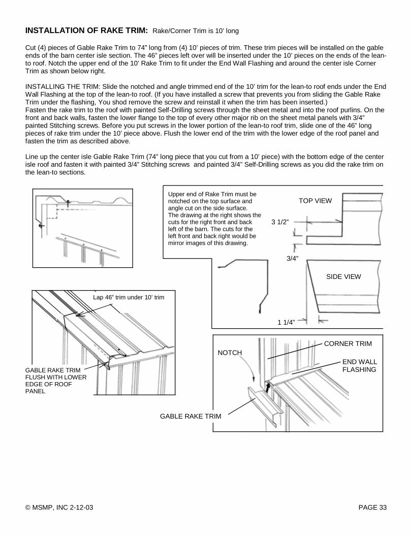
INSTALLATION OF RAKE TRIM: Rake/Corner Trim is 10’ long Cut (4) pieces of Gable Rake Trim to 74” long from (4) 10’ pieces of trim. These trim pieces will be installed on the gable ends of the barn center isle section. The 46” pieces left over will be inserted under the 10’ pieces on the ends of the lean-to roof. Notch the upper end of the 10’ Rake Trim to fit under the End Wall Flashing and around the center isle Corner Trim as shown below right. INSTALLING THE TRIM: Slide the notched and angle trimmed end of the 10’ trim for the lean-to roof ends under the End Wall Flashing at the top of the lean-to roof. (If you have installed a screw that prevents you from sliding the Gable Rake Trim under the flashing, You shod remove the screw and reinstall it when the trim has been inserted.) Fasten the rake trim to the roof with painted Self-Drilling screws through the sheet metal and into the roof purlins. On the front and back walls, fasten the lower flange to the top of every other major rib on the sheet metal panels with 3/4” painted Stitching screws. Before you put screws in the lower portion of the lean-to roof trim, slide one of the 46” long pieces of rake trim under the 10’ piece above. Flush the lower end of the trim with the lower edge of the roof panel and fasten the trim as described above. Line up the center isle Gable Rake Trim (74” long piece that you cut from a 10’ piece) with the bottom edge of the center isle roof and fasten it with painted 3/4” Stitching screws and painted 3/4” Self-Drilling screws as you did the rake trim on the lean-to sections.
NOTCH END WALL FLASHING
CORNER TRIM
PAGE 33 © MSMP, INC 2-12-03
GABLE RAKE TRIM
3 1/2”
3/4”
1 1/4”
SIDE VIEW
TOP VIEW Upper end of Rake Trim must be notched on the top surface and angle cut on the side surface. The drawing at the right shows the cuts for the right front and back left of the barn. The cuts for the left front and back right would be mirror images of this drawing.
GABLE RAKE TRIM FLUSH WITH LOWER EDGE OF ROOF PANEL
Lap 46” trim under 10’ trim

INSTALLATION OF THE RIDGE CAP: RIDGE CAP COMES IN 10' LENGTHS. OUTSIDE FOAM CLOSURE STRIPS WILL BE INSTALLED UNDER BOTH SIDES OF THE RIDGE CAP. Starting at one end of the roof place a piece of Ridge Cap on the peak of the roof, flush with the front surface of the rake trim. Install Outside Closure strips under the edges of the Ridge Cap and fasten the Ridge Cap to the tops of the major roof metal ribs with 3/4” Stitching Screws. NOTE: The next length of Ridge Cap should overlap the previous length about 3”. Do not install the screws in the joint until the next piece is in place.
RIDGE CAP
OUTSIDE CLOSURE STRIP (ON BOTH SIDES OF RIDGE CAP) 3/4” STITCHING SCREW
SCREWS INTO TOP OF MAJOR RIBS
ASSEMBLY OF END CAPS: Place End Caps on the peak of the barn at the front and back gable ends and fasten them on top through the ridge cap and into the frame with painted 3/4” Self Drilling screws. Fasten the lower front flange to the front or back sheet metal panels with painted 3/4” Stitching screws into the top of the major ribs.
PAGE 34 © MSMP, INC 2-12-03
3/4” STITCHING SCREW 3/4" SELF-DRILLING SCREW WITH RUBBER WASHER
INSTALL INSIDE CLOSURE STRIPS AT EAVE On the inside of the barn (lean-to and center isle), install Inside Foam Closure Strips between the eave trim flange and the roof panels . Peal the strips off the backing paper, pull down the eave trim flange and work the closure strips between the flange and the roof panels. The ends of the strips will interlock at a major rib. Start in one corner and work to the other.
PULL FLANGE DOWN
FOAM CLOSURE INTERLOCK
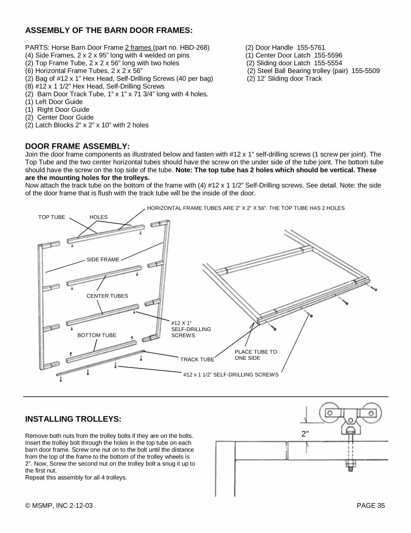
DOOR FRAME ASSEMBLY: Join the door frame components as illustrated below and fasten with #12 x 1” self-drilling screws (1 screw per joint). The Top Tube and the two center horizontal tubes should have the screw on the under side of the tube joint. The bottom tube should have the screw on the top side of the tube. Note: The top tube has 2 holes which should be vertical. These are the mounting holes for the trolleys. Now attach the track tube on the bottom of the frame with (4) #12 x 1 1/2” Self-Drilling screws. See detail. Note: the side of the door frame that is flush with the track tube will be the inside of the door.
TOP TUBE HOLES
SIDE FRAME
CENTER TUBES
BOTTOM TUBE
#12 X 1” SELF-DRILLING SCREWS
TRACK TUBE
#12 x 1 1/2” SELF-DRILLING SCREWS
INSTALLING TROLLEYS: Remove both nuts from the trolley bolts if they are on the bolts. Insert the trolley bolt through the holes in the top tube on each barn door frame. Screw one nut on to the bolt until the distance from the top of the frame to the bottom of the trolley wheels is 2”. Now, Screw the second nut on the trolley bolt a snug it up to the first nut. Repeat this assembly for all 4 trolleys.
2"
PAGE 35 © MSMP, INC 2-12-03
ASSEMBLY OF THE BARN DOOR FRAMES: PARTS: Horse Barn Door Frame 2 frames (part no. HBD-268) (2) Door Handle 155-5761 (4) Side Frames, 2 x 2 x 95” long with 4 welded on pins (1) Center Door Latch 155-5596 (2) Top Frame Tube, 2 x 2 x 56” long with two holes (2) Sliding door Latch 155-5554 (6) Horizontal Frame Tubes, 2 x 2 x 56” (2) Steel Ball Bearing trolley (pair) 155-5509 (2) Bag of #12 x 1” Hex Head, Self-Drilling Screws (40 per bag) (2) 12’ Sliding door Track (8) #12 x 1 1/2” Hex Head, Self-Drilling Screws (2) Barn Door Track Tube, 1” x 1” x 71 3/4” long with 4 holes. (1) Left Door Guide (1) Right Door Guide (2) Center Door Guide (2) Latch Blocks 2” x 2” x 10” with 2 holes
HORIZONTAL FRAME TUBES ARE 2” X 2” X 56”. THE TOP TUBE HAS 2 HOLES
PLACE TUBE TO ONE SIDE

HANGING THE BARN DOOR FRAMES: Lift the doors and slide the door trolleys into the door track on the barn. Versatube Left and Right Door Guides: Line the guides up with the track tube on the bottom of the door in the “U” shaped section of the door guide. Adjust the guide in or out until the door hangs plum and fasten the Door Guide to the barn door Jamb with #12 x 1” self-drilling screws.
DOOR TRACK
DOOR GUIDE (RIGHT)
DOOR FRAME
BARN DOOR JAMB
DOOR GUIDE DOOR TRACK TUBE
PAGE 36 © MSMP, INC 2-12-03
#12 X 1” SELF-DRILLING SCREW
60”
INSTALLING DOOR STOPS: Attach a Door Stop on both sides of the barn door opening with #12 x 1” self-drilling screws 60” from the door jamb as shown above.
INSTALLING CENTER GUIDE: Cut a pressure treated 4 x 4 wood post to 18” long. Mount the Sliding Door Center Guide on one end of the post, square and centered with #12 x 1” self-drilling screws. Dig a 8” diameter hole 18” deep in the ground directly under the point where the two sliding doors come together. Place the wood post with the center guide in the hole and using a measuring tape and a string line drawn between the two door guides at the door jambs position the center guide to line up with door guides. Center of the door way, at the same height as the side guides. Pack some dirt around the bottom of the post to and brace it at the top as needed. Pour concrete in the hole to within 2” of grade. Re-check the guide position before the concrete sets.
CENTER GUIDE TO 4 X 4 X 18 POST
GUIDE STRING
DOOR GUIDE
GRADE
8” X 18” HOLE
DIRT
CONCRETE
18”
8”

INSTALLING SHEET METAL AND TRIM ON BARN DOORS: (4) Pro-Rib Panels 95” long STEP 1: TRIMMING AND FASTENING SHEET METAL PANELS TO THE SLIDING DOORS Locate the (4) 95” sheet metal panels for your barn doors. The first step is to trim the overlap edge of two panels and the underlap edge of the other two panels. Trim the edge ribs down the center as shown in rib trim detail below. Each door frame will have two sheet metal panels. One with the trimmed overlap edge and one with the trimmed under-lap edge. The trimmed edges will go to the outside of the frame. The center lap joint will be typical. See the illustration below for panel location. Use painted 3/4” Self-drilling screws to fasten the panels to the frame. Like the side panels use one screw on both sides of the major ribs at the top and bottom of the door and one screw on one side at other locations. Repeat the assembly for the other door. STEP 2: ATTACHING VERTICAL DOOR TRIM TO SIDES OF DOORS. (8’ Vertical Door Trim) Fasten the trim to the sides of the doors as shown below. Use flat head (pan head screws) on the inside edge of the door frame (the sides where the doors come together) and Painted 3/4” Self-Drilling Screws through the sheet metal into the door frame members on the front and outside edge of the doors.
#10 PAN HEAD SCREW PAGE 37 © MSMP, INC 2-12-03
OVERLAP TRIMMED EDGE UNDERLAP TRIMMED EDGE
2"
2 1/4"
13/16"
3/4"
VERTICAL DOOR TRIM
VERTICAL DOOR TRIM
USE PAINTED 3/4’ SELF-DRILLING SCREW ON OUTSIDE EDGE AND PAN HEAD SCREW ON INSIDE EDGE
DOOR TRIM DETAIL
DOOR FRAME
DOOR FRAME
72"
3/4" PAINTED SELF-DRILLING SCREW
FRONT OF THE BARN

PAGE 38 © MSMP, INC 2-12-03
INSTALLING SLIDING DOOR LATCHES STEP 1: INSTALLING LATCH BLOCKS: (2” x 2” x 10’’ with two holes.) Position the Latch Blocks flush with the inside of the door jamb as shown 31” from the bottom of the base rail and fasten to the door jamb with #12 x 1” x 3” Self-Drilling Screws. Repeat the opposite door jamb. STEP 2: DRILLING CATCH HOLE FOR DOOR SIDE LATCH: With the Sliding door closed, measure and drill a 3/8” hole through one wall of the lower horizontal cross brace in the door frame. (the side next to the door jamb) STEP 3: INSTALLING THE SIDE LATCHES: Position the Sliding Door Side Latch on the door jamb flush with the back of the jamb and 3/4” from the top of the latch plate to the top of the door horizontal cross brace as shown below. Attach the latch plate to the door jamb with #12 x 1” Self-Drilling screws. Screw the threaded latch rod in or out until the hook end fits and tightens properly in the hole you drilled in the door horizontal cross brace. (Note: the catch bracket supplied with the Sliding Door Side Latch will not be used. Now, install the other latch on the other door jamb.
31”
LATCH BLOCK
#12 X 3” SELF-DRILLING SCREWS
LOWER HORIZONTAL CROSS BRACE
VIEW FROM INSIDE OF THE BARN
3/8” HOLE 1 WALL
1/2”
1 3/4”
3/4” LATCH BLOCK
LATCH PLATE
THREADED LATCH ROD
#12 X 1” SELF-DRILLING SCREW
LOWER HORIZONTAL CROSS BRACE
STEP 4: INSTALLING CENTER LATCH From the inside of the barn, drill a 3/8” hole through one wall of the vertical door frame member on the door frame to the right 2” above the lower horizontal cross brace. Mount the Center Latch on the lower horizontal cross brace of the left door as shown with #12 x 1” Self-Drilling screws. Adjust the threaded latch rod until the latch pulls the doors tightly together.
2”
CENTER LATCH 3/8” HOLE 1 WALL