mems resistor laboratory dr. lynn fuller - rit - people · © march 13, 2013 dr. lynn fuller,...
TRANSCRIPT

© March 13, 2013 Dr. Lynn Fuller, Professor
Resistor Lab
Page 1
Rochester Institute of Technology
Microelectronic Engineering
ROCHESTER INSTITUTE OF TECHNOLOGYMICROELECTRONIC ENGINEERING
MEMS Resistor Laboratory
Dr. Lynn Fullerwebpage: http://people.rit.edu/lffeee
Electrical and Microelectronic EngineeringRochester Institute of Technology
82 Lomb Memorial DriveRochester, NY 14623-5604
Tel (585) 475-2035Fax (585) 475-5041
Email: [email protected] webpage: http://www.microe.rit.edu
3-13-2013 Resistor_lab.ppt

© March 13, 2013 Dr. Lynn Fuller, Professor
Resistor Lab
Page 2
Rochester Institute of Technology
Microelectronic Engineering
OUTLINE
Objective
Theory
Experimental Set Up
Measurements
Results
Discussion
References
Lab Instructors Notes

© March 13, 2013 Dr. Lynn Fuller, Professor
Resistor Lab
Page 3
Rochester Institute of Technology
Microelectronic Engineering
OBJECTIVE
The objective of this lab is to investigate integrated MEMS
resistors and their applications as heaters, sensors and actuators.
4000x4000 chip
2200x2200 diaphragm

© March 13, 2013 Dr. Lynn Fuller, Professor
Resistor Lab
Page 4
Rochester Institute of Technology
Microelectronic Engineering
CLOSE UP OF RESISTORS AND THERMOCOUPLE
Red N+ Polysilicon Resistor
60 um x 20 um
+ 30 to contact so L/W ~ 6
Green P+ Diffused Resistor
200 um wide x 180 um long
Aluminum – N+ Poly
Thermocouple

© March 13, 2013 Dr. Lynn Fuller, Professor
Resistor Lab
Page 5
Rochester Institute of Technology
Microelectronic Engineering
RESISTORS ON THIN DIAPHRAGM
With Vacuum Chuck On
© March 13, 2013 Dr. Lynn Fuller, Professor
Resistor Lab
Page 6
Rochester Institute of Technology
Microelectronic Engineering
MOVIE OF DIAPHRAGM DEFLECTION
movie click to play
© March 13, 2013 Dr. Lynn Fuller, Professor
Resistor Lab
Page 7
Rochester Institute of Technology
Microelectronic Engineering
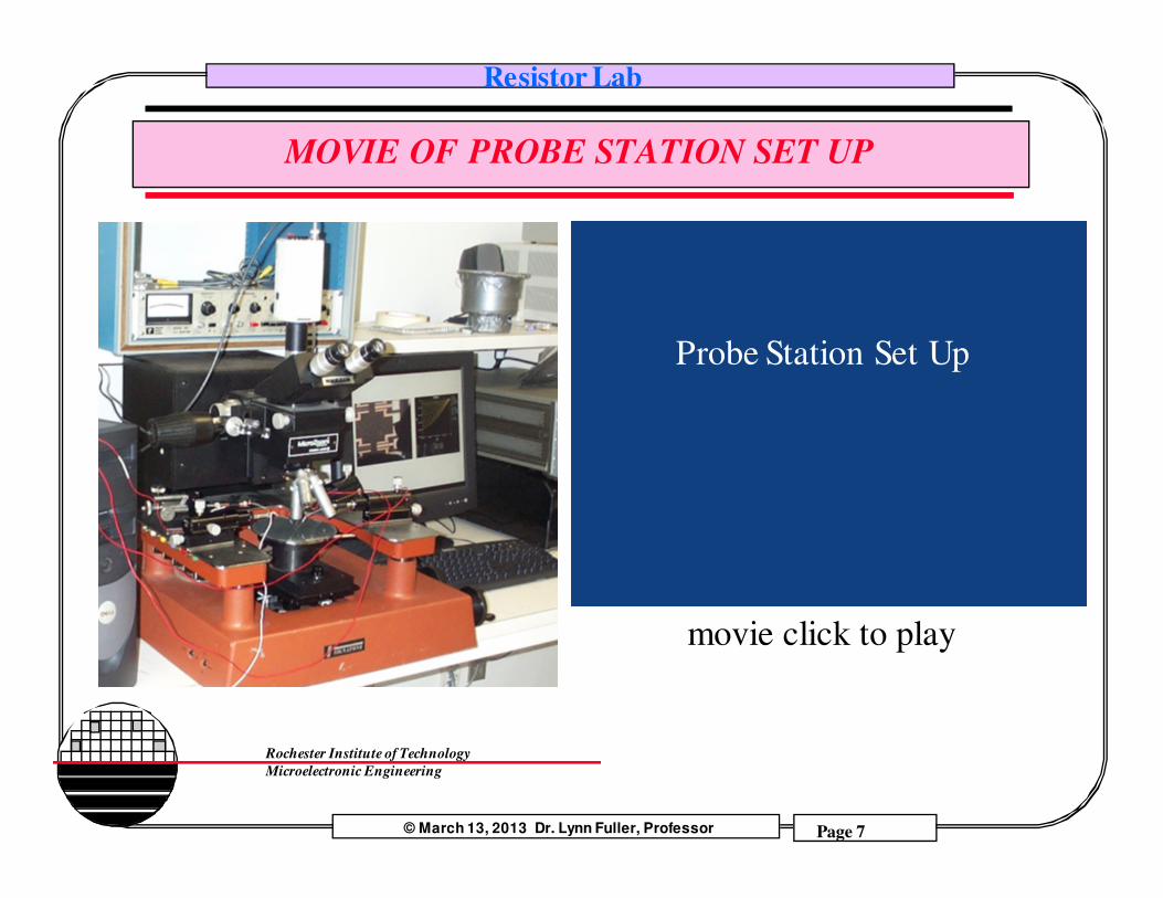
MOVIE OF PROBE STATION SET UP
Probe Station Set Up
movie click to play
© March 13, 2013 Dr. Lynn Fuller, Professor
Resistor Lab
Page 8
Rochester Institute of Technology
Microelectronic Engineering
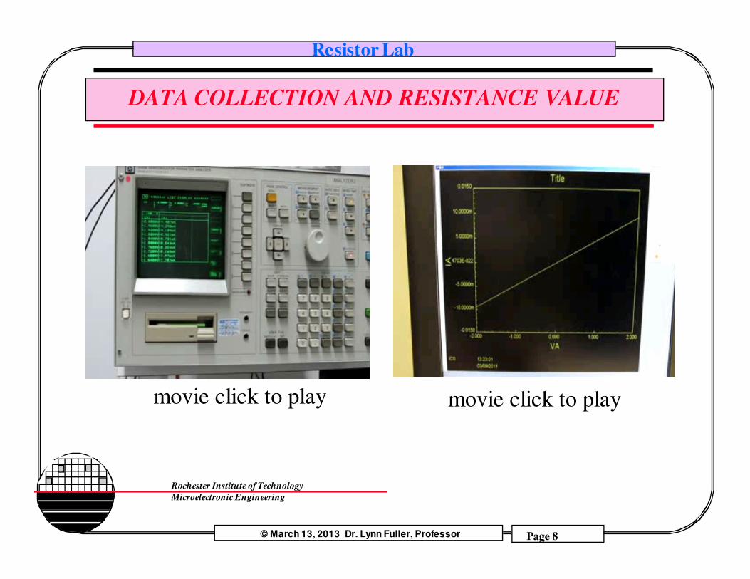
DATA COLLECTION AND RESISTANCE VALUE
movie click to play movie click to play
© March 13, 2013 Dr. Lynn Fuller, Professor
Resistor Lab
Page 9
Rochester Institute of Technology
Microelectronic Engineering
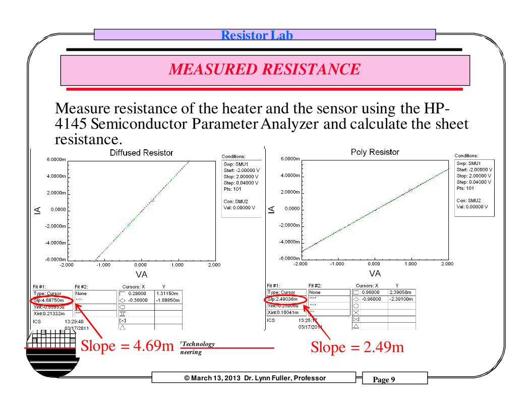
MEASURED RESISTANCE
Measure resistance of the heater and the sensor using the HP-4145 Semiconductor Parameter Analyzer and calculate the sheet resistance.
Slope = 2.49mSlope = 4.69m

© March 13, 2013 Dr. Lynn Fuller, Professor
Resistor Lab
Page 10
Rochester Institute of Technology
Microelectronic Engineering
CALCULATIONS
Using the data on the previous page calculate
R = 1 / slope
For both diffused and poly resistors.
Calculate Rhos
R = Rhos L/W
For both diffused and poly resistors.
© March 13, 2013 Dr. Lynn Fuller, Professor
Resistor Lab
Page 11
Rochester Institute of Technology
Microelectronic Engineering
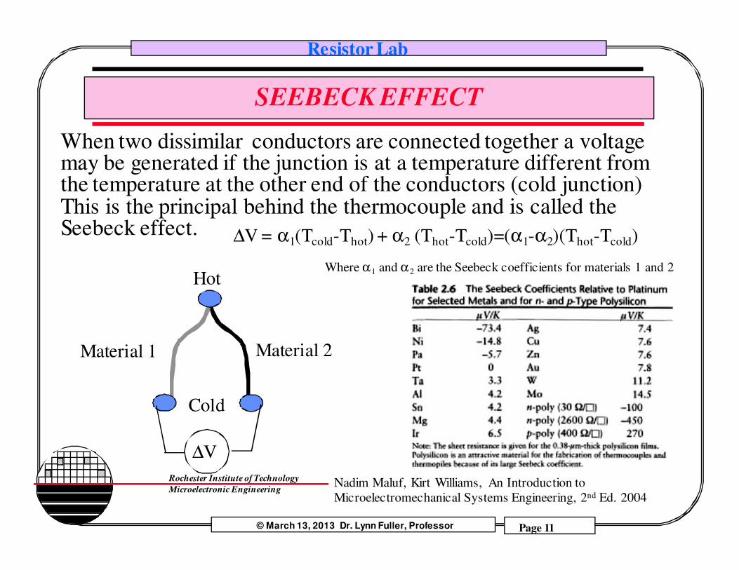
SEEBECK EFFECT
When two dissimilar conductors are connected together a voltage may be generated if the junction is at a temperature different from the temperature at the other end of the conductors (cold junction) This is the principal behind the thermocouple and is called the Seebeck effect.
∆V
Material 2Material 1
Hot
Cold
Nadim Maluf, Kirt Williams, An Introduction to
Microelectromechanical Systems Engineering, 2nd Ed. 2004
∆V = α1(Tcold-Thot) + α2 (Thot-Tcold)=(α1-α2)(Thot-Tcold)
Where α1 and α2 are the Seebeck coefficients for materials 1 and 2

© March 13, 2013 Dr. Lynn Fuller, Professor
Resistor Lab
Page 12
Rochester Institute of Technology
Microelectronic Engineering
THERMAL RESISTANCE
200um
2200 um
Thickness ~ 30 um
Rth = 1/C L/Area
whereC=thermal conductivityL= length of thermal path between heater and ambientArea = cross sectional areaof the path to ambient
Rth ~ 1/1.5 1000/(500x30) = 444°C/watt
but 4 paths in parallel gives ~ 111 °C/watt
© March 13, 2013 Dr. Lynn Fuller, Professor
Resistor Lab
Page 13
Rochester Institute of Technology
Microelectronic Engineering
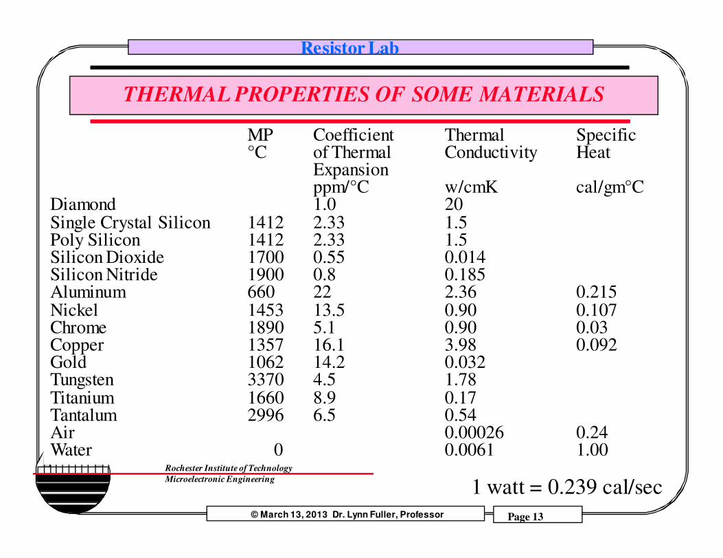
THERMAL PROPERTIES OF SOME MATERIALS
MP Coefficient Thermal Specific°C of Thermal Conductivity Heat
Expansionppm/°C w/cmK cal/gm°C
Diamond 1.0 20Single Crystal Silicon 1412 2.33 1.5Poly Silicon 1412 2.33 1.5Silicon Dioxide 1700 0.55 0.014Silicon Nitride 1900 0.8 0.185Aluminum 660 22 2.36 0.215Nickel 1453 13.5 0.90 0.107Chrome 1890 5.1 0.90 0.03Copper 1357 16.1 3.98 0.092Gold 1062 14.2 0.032Tungsten 3370 4.5 1.78Titanium 1660 8.9 0.17Tantalum 2996 6.5 0.54Air 0.00026 0.24Water 0 0.0061 1.00
1 watt = 0.239 cal/sec
© March 13, 2013 Dr. Lynn Fuller, Professor
Resistor Lab
Page 14
Rochester Institute of Technology
Microelectronic Engineering
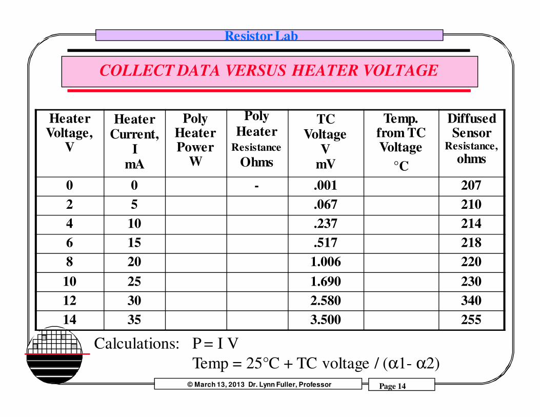
COLLECT DATA VERSUS HEATER VOLTAGE
Heater Voltage,
V
Heater Current,
ImA
Poly Heater Power
W
Poly
HeaterResistance
Ohms
TC Voltage
V mV
Temp. from TC Voltage
°C
Diffused Sensor
Resistance,
ohms
0 0 - .001 207
2 5 .067 210
4 10 .237 214
6 15 .517 218
8 20 1.006 220
10 25 1.690 230
12 30 2.580 340
14 35 3.500 255
Calculations: P = I V
Temp = 25°C + TC voltage / (α1- α2)

© March 13, 2013 Dr. Lynn Fuller, Professor
Resistor Lab
Page 15
Rochester Institute of Technology
Microelectronic Engineering
RESISTOR TEMPERATURE RESPONSE
I
V1 2 3 4
-4 -3 -2 -1
-0.002
-0.003
-0.004
0.004
0.003
0.002
Cold
Hot
L,W,xj do not change with light, µn and µp does not change with light but can change with temperature, n and p does not change much in heavy doped semiconductors (that is, n and p is determined by doping)
R = ρ L/(W xj) ohms
ρ = 1/( qµnn + qµpp) Slope = 4.37m
Slope = 4.69m
Heat provided by 10V on Poly Resistor

© March 13, 2013 Dr. Lynn Fuller, Professor
Resistor Lab
Page 16
Rochester Institute of Technology
Microelectronic Engineering
CALCULATION OF RESISTANCE
© March 13, 2013 Dr. Lynn Fuller, Professor
Resistor Lab
Page 17
Rochester Institute of Technology
Microelectronic Engineering
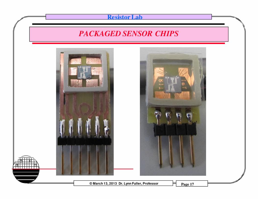
PACKAGED SENSOR CHIPS
© March 13, 2013 Dr. Lynn Fuller, Professor
Resistor Lab
Page 18
Rochester Institute of Technology
Microelectronic Engineering
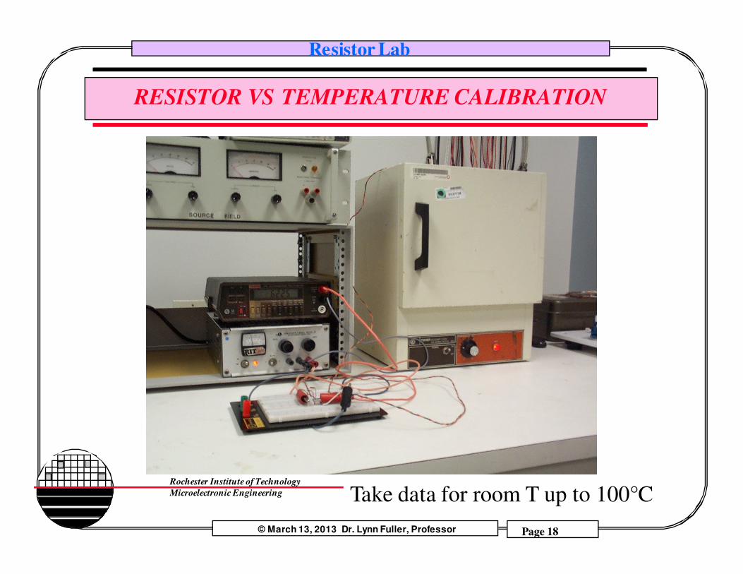
RESISTOR VS TEMPERATURE CALIBRATION
Take data for room T up to 100°C
© March 13, 2013 Dr. Lynn Fuller, Professor
Resistor Lab
Page 19
Rochester Institute of Technology
Microelectronic Engineering
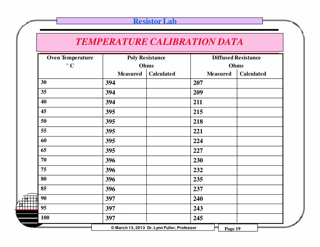
TEMPERATURE CALIBRATION DATA
Oven Temperature
° C
Poly Resistance
Ohms
Measured Calculated
Diffused Resistance
Ohms
Measured Calculated
30 394 207
35 394 209
40 394 211
45 395 215
50 395 218
55 395 221
60 395 224
65 395 227
70 396 230
75 396 232
80 396 235
85 396 237
90 397 240
95 397 243
100 397 245

© March 13, 2013 Dr. Lynn Fuller, Professor
Resistor Lab
Page 20
Rochester Institute of Technology
Microelectronic Engineering
ACTUATOR CHARACTERIZATION
Supply heater voltage from a signal generator and try to evaluate
the speed of response of the diaphragm movement.
Vcc = 15V
Vin
Heater
Hz100
SIGNAL GENERATOR

© March 13, 2013 Dr. Lynn Fuller, Professor
Resistor Lab
Page 21
Rochester Institute of Technology
Microelectronic Engineering
SEE IT MOVE – HEAR IT
movie click to play
movie click to play

© March 13, 2013 Dr. Lynn Fuller, Professor
Resistor Lab
Page 22
Rochester Institute of Technology
Microelectronic Engineering
REFERENCES
1. Handbook of Modern Sensors, Jacob Faraden, Springer
2. Dr. Fuller’s webpages, http://people.rit.edu/lffeee

© March 13, 2013 Dr. Lynn Fuller, Professor
Resistor Lab
Page 23
Rochester Institute of Technology
Microelectronic Engineering
HOMEWORK
1. Do a more exact calculation of the thermal resistance of the
diaphragm shown on page 12.
2. Why can’t we calibrate the thermocouple using the oven?
3. Does our data show a square law relationship for temperature vs.
voltage to the heater? Why?
4. Plot the data and calculations from page 19. What conclusions can
be made?
5. Compare heater and sensor resistance vs. temperature data from
page 14 to that from page 19.
6. Discuss the theoretical frequency response of the diaphragm.
7. Write a ~150 word abstract for this lab project.

© March 13, 2013 Dr. Lynn Fuller, Professor
Resistor Lab
Page 24
Rochester Institute of Technology
Microelectronic Engineering
INSTRUCTORS CHECK LIST
Show MEMS chipTake PictureApply VacuumTake PictureMeasure Heater Resistance using HP4145Measure Sensor Resistance using HP4145Measure Sensor Resistance with and without lightMeasure Heater Resistor with voltmeter and current meterMeasure Heater I and V at 50 mV applied (no self heating)Measure Heater I and V at 15 V applied (self heating ~1/4watt)Take picture of diaphragm deflection due to heatingTake data for tableTake data for Sensor Resistor in ovenTake data for Heater Resistor in ovenEvaluate frequency response of heat driven diaphragm movement