mems-based state feedback control of multi-body...
TRANSCRIPT

MEMS-based State Feedback Control of Multi-Body Hydraulic
Manipulator
Janne Honkakorpi1, Juho Vihonen2 and Jouni Mattila1
Abstract— This paper presents closed-loop state feedbackmotion control of a heavy-duty hydraulic manipulator usingsolely micro-electro-mechanical systems (MEMS) rate gyro-scopes and linear accelerometers for joint angular position,velocity and acceleration feedback. For benchmarking, incre-mental encoders with 2 million counts per revolution are alsoused to supply the joint motion state feedback. The two motionstate estimation methods are compared using Cartesian pathtrajectory closed-loop control experiments with both positionfeedback-based proportional control and motion state-basedfeedback control. The experiments show that the proposedMEMS-based state feedback control yields comparable trackingresults compared with the high accuracy encoder. Furthermore,the MEMS-based angular acceleration estimation in particularis free from typical differentiation induced noise amplificationand post-filtering phase-lag.
I. INTRODUCTION
Hydraulic control systems suffer from inherent low system
damping and thus an increase in damping is needed to allow
a higher open-loop controller gain for high performance
tracking control [1]. In servo-hydraulics, closed-loop pole
placement is a well-established approach that requires full
state feedback from actuator position, velocity and acceler-
ation or a state observer design, see e.g. [2].
High accuracy and resolution joint position measurement
is relatively straightforward with commercial contact-type
angular sensors, such as magnetic or optical rotatory en-
coders that can easily provide accuracy of more than 1 arcsec.
However, in addition to a high price, the drawback of this
technology is two-folded. Firstly, these sensors require a
mechanical contact interface to the manipulator rotating axles
that is subject to wear and failures in harsh outdoor environ-
ments. Moreover, due to mechanical interface complexity
and high precision mounting requirements, these sensors
are costly to install to new manipulators joints and even
more expensive to retro-fit into existing machines. Secondly,
obtaining low-noise low-delay estimates of the joint angular
velocities and angular accelerations is a less trivial task.
Whenever first and second order time derivatives of po-
sition are indirectly computed at high sampling rates using
the traditional approach of single/double differentiation of
position, or using predictive post-filtering on the differenti-
ated signals, high-frequency perturbations and quantization
*This work was supported by the Academy of Finland under theproject “Sensor Network Based Intelligent Condition Monitoring of MobileMachinery”, grant no. 133273.
1J. Honkakorpi and J. Mattila are with the Department of IntelligentHydraulics and Automation, Tampere University of Technology, FI-33101,Finland. e-mail: [email protected]
2J. Vihonen is with the Department of Signal Processing, Tampere Uni-versity of Technology, FI-33101, Finland. e-mail: [email protected]
effects are greatly amplified, e.g. [3]. Likewise, linear state
observation and Kalman filter techniques avoid the need of
differentiation but require system models to be available [4],
[5], which may not be simple. Time-based encoder pulse
counting techniques rely on high resolution time stamps to be
available of encoder pulse count events, which typically leads
to the use of external timer/counter hardware and increases
the system cost further [6].
We consider full state feedback motion control of a heavy-
duty hydraulic HIAB 031 manipulator, where micro-electro-
mechanical systems (MEMS) components are utilized for a
low-cost “strap-down” implementation. We will counter the
aforementioned problems of indirect motion state estimation
by applying a novel multi-MEMS configuration we have
recently proposed in [7]. The axle-wise contact-free direct
motion state sensing is founded solely on MEMS rate
gyro and accelerometer readings, since metallic frames of
many robotic manipulators make optional MEMS sensors
such as magnetometers [8] often unusable. By geometrically
modeling the linear and angular motion effects involved, we
can reconstruct the HIAB 031 manipulator’s “true” joint po-
sitions, angular velocities and angular accelerations directly
without unwanted phase delay or distortion.
The focus of our paper is on manipulator vertical plane
high-bandwidth motion control for analytical simplicity. To
allow a fair performance verification, the developed MEMS-
based state feedback controller is compared to state feedback
control results obtained using highly accurate incremental
encoder feedback with an angular resolution of 2 × 10⁶ in-
crements per revolution. Our robotic Cartesian space motion
control experiments show that the dynamic response and path
tracking performance of the cost-effective and easy-to install
MEMS-based full state feedback controller is comparable to
the high accuracy encoder results. Therefore, we consider
the applied low-cost MEMS configuration promising and
a significant step forward from our earlier motion control
case [9], where a 1-DOF hydraulic mock-up was studied.
This paper is organized as follows. Sect. II provides the ba-
sis of the motion state estimation using MEMS components.
Application of the estimated motion states in closed-loop
state feedback control is also presented. Sect. III presents
the experimental work, where our latest results concerning
MEMS-based full motion state estimation of a multi-body
linkage assembly in relatively fast motion are applied to the
full state feedback control of full-size heavy-duty of HIAB
031 hydraulic manipulator. Finally, Sect. IV discusses the
results and draws the relevant conclusions.
2013 IEEE/RSJ International Conference onIntelligent Robots and Systems (IROS)November 3-7, 2013. Tokyo, Japan
978-1-4673-6357-0/13/$31.00 ©2013 IEEE 4419
II. MANIPULATOR MOTION MODEL AND ESTIMATION
In this section, we provide a geometrical observational
model for motion state estimation of a multi-body manipu-
lator based on MEMS rate gyroscopes and linear accelerome-
ters. The presented estimation approach is applicable to fully
three-dimensional motion for a manipulator consisting of an
arbitrary amount of rigid bodies. Then, the widely-applicable
full state feedback motion control is also discussed briefly.
A. Direct manipulator motion state estimation using MEMS
accelerometers and rate gyros
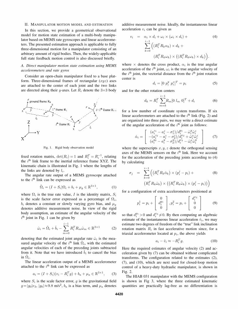
Consider an open-chain manipulator fixed to a base plat-
form. Three-dimensional frames of rectangular (xyz) axes
are attached to the center of each joint and the two links
are directed along their y-axes. Let Ri denote the 3×3 body
Fig. 1. Rigid body observation model
fixed rotation matrix, det(Ri) = 1 and RTi =R−1
i , relating
the ith link frame to the inertial reference frame XYZ. The
kinematic chain is illustrated in Fig. 1 where the lengths of
the links are denoted by li.The angular rate output of a MEMS gyroscope attached
to the ith link can be expressed as
Ωi = (I + Si)Ωi + bi + µg ∈ R3×1, (1)
where Ωi is the true rate value, I is the identity matrix, Si
is the scale factor error expressed as a percentage of Ωi,
bi denotes a constant or slowly varying gyro bias, and µg
denotes additive measurement noise. In view of the rigid
body assumption, an estimate of the angular velocity of the
ith joint in Fig. 1 can be given by
ωi = Ωi + bi −i−1∑
m=0
RTi Rmωm ∈ R
3×1 (2)
denoting that the estimated joint angular rate ωi is the mea-
sured angular velocity of the ith link Ωi, with the estimated
angular velocities of each of the preceding joints subtracted
from it. Note that we have introduced bi to cancel the bias
in Ωi.
The linear acceleration output of a MEMS accelerometer
attached to the ith link can be expressed as
ai = (I + Si)(vi −RTi g) + ba + µa ∈ R
3×1, (3)
where Si is the scale factor error, g is the gravitational field
g= |g0|e3, |g0|≈9.8 m/s2, ba is a bias term, and µa denotes
additive measurement noise. Ideally, the instantaneous linear
acceleration vi can be given as
vi = αi × di + ωi × (ωi × di) + (4)i−1∑
k=0
(
(RTi Rkαk)× dk +
(RTi Rkωk)×
(
(RTi Rkωk)× dk
)
)
.
where × denotes the cross product, αi is the true angular
acceleration of the ith joint, ωi is the true angular velocity of
the ith joint, the vectorial distance from the ith joint rotation
center is
di = [0 pyi pzi ]T = pi (5)
and for the other rotation centers
dk = RTi
i−1∑
m=k
Rm[0 lm 0]T + di (6)
for a low number of coordinate system transforms. If six
linear accelerometers are attached to the ith link (Fig. 2) and
are organized into three pairs, we may write a direct estimate
of the angular acceleration of the ith joint as follows:
αi =
(az1i − azi − σz1)/d
y1
i − ωyi ω
zi
−(az2i − azi − σz2)/d
x2i + ωx
i ωzi
(ay2
i − ayi − σy2 )/d
x2i − ωx
i ωyi
(7)
where the superscripts x, y, z denote the orthogonal sensing
axes of the MEMS sensors on the ith link. Here we account
for the acceleration of the preceding joints according to (4)
by calculating
σj =i−1∑
k=0
(
(
RTi Rkαk
)
× (pji − pi) + (8)
(
RTi Rkωk
)
×((
RTi Rkωk
)
× (pji − pi))
)
for a configuration of extra accelerometers positioned at
p1i = pi +
0dy1
i
0
, p2i = pi +
dx2i
00
(9)
so that dy1
i >0 and dx2i 6=0. By then computing an algebraic
estimate of the instantaneous linear acceleration vi, we may
estimate two degrees of freedom of the “true” link inclination
rotation matrix Ri in fast accelerative motion since, for a
triaxial accelerometer located at pi, the above yields
ai − vi ≈ −RTi g. (10)
Here the required estimates of angular velocity (2) and ac-
celeration given by (7) can be obtained without complicated
transforms. The configuration related to the estimates (2),
(7), and (10), which are next used for closed-loop motion
control of a heavy-duty hydraulic manipulator, is shown in
Fig. 2.
The HIAB 031 manipulator with the MEMS configuration
is shown in Fig 3, where the three estimated kinematic
quantities are practically lag-free as no differentiation is
4420

p2iay2
i
az2i
ith joint ωzi
ωxi
ωyi
axi
azi
p1i
az1i
ayi
i+1th joint
pi ith link
Fig. 2. A configuration of six linear accelerometers and a triaxial rate gyroattached to the ith link. The extra single and biaxial accelerometers with theirsensitive axes shown are used for direct angular acceleration sensing.
required. Note that because of low angular dynamics of the
manipulator, the effects of the MEMS scale factor errors can
be considered small. Under the rigid body assumption, real-
time estimates of the joint angles can be given by
φi = θi − θi−1, i = 1, 2, (11)
which denotes pair-wise subtraction of successive link in-
clination estimates θi of the “true” rotation matrix Ri.
The “ground” frame’s rotation around x-axis is here simply
included by using the horizontal position with respect to the
gravity as our reference, i.e. θ0 = 0 deg. High-bandwidth
estimates of θi are available by applying complementary
and Kalman filtering to the accelerometer and gyroscope
readings, please see [7] for further discussion.
R0
l1
l2
p1
az1
R1
ay1
az11
Ωx1
p11
R2
p2
ay2
az2
Ωx2
p12 a
z12
m
P(x,y)
Fig. 3. MEMS sensor configuration on the hydraulic manipulator, l0 =0m l1 = 1.6m, l2 = 1.65m,m = 475 kg. For clarity, we assume thebase platform’s rotation R0 = I , where I is the 3 × 3 identity matrix.The MEMS on the first link are located at points p1 = [0 0.21 0.23]T mand p1
1= [0 1.33 0.16]T m respective to R1. The MEMS on the second
link are at points p2 = [0 0.24 0.22]T m and p12= [0 1.32 0.145]T m
respective to R2. The initial inclination misalignment between the MEMSsensor orientations and the first link angle was 6.8 deg and 7.7 deg on thesecond link.
B. Hydraulic manipulator closed-loop state feedback control
Assuming a linear time-invariant system and treating all
gravitational, inertial, centripetal and frictional terms as
external disturbances, a hydraulic closed-loop position servo-
system can be modeled with a linear second order transfer
function between valve control input and joint velocity as
H(s) =V (s)
U(s)=
Kqa · ω2n
s2 + 2δnωns+ ω2n
(12)
where V (s) and U(s) are the output velocity and control
input, Kqa is the actuator velocity gain, δn is the natural
damping ratio and ωn is the natural frequency of the sys-
tem [10]. A linear model of a full state feedback closed-loop
control system can then be represented as shown in Fig. 4.
Although a simplification, the use of a linearized model
is typically more relevant from the control perspective, since
many applications of various control strategies rely on the
use of a linear model. The control system consists of an
inner second order velocity control loop with feedback gains
Kv and Ka, an outer unity feedback, and a gain Kp for the
position error. Incorporating the feedback gains Kv and Ka
into the transfer function (12) the inner velocity control loop
becomes
Hvel(s) =V (s)
U(s)
=Kqa · ω
2n
s2 + (2δnωn +KaKqaω2n)s+ (1 +KvKqa)ω2
n
. (13)
Comparing transfer functions (12) and (13) we can see that
the servo system with state feedback has a new damping
ratio
δ′
n =2δn +KaKqaωn
2√
1 +KvKqa
(14)
and a new natural frequency
ω′
n = ωn
√
1 +KvKqa. (15)
From (14) and (15) it can be seen that the system damping in-
creases with the acceleration feedback gain Ka. The natural
frequency of the state feedback control system increases with
the feedback gain Kv but at the same time, the damping ratio
becomes smaller. Finally, the closed-loop transfer function
from the reference position input X(s) to the position output
Y (s) for the control loop in Fig. 4 is given by
Hcl(s) =Y (s)
X(s)(16)
where Y (s) = KpKqaω2n
and X(s) = s3 + (2δnωn +KaKqaω2n)s
2+
(ω2n +KvKqaω
2n)s+KpKqaω
2n.
In the experiments to follow the presented controller is
applied individually to both joints of the manipulator and
all coupling effects between the joints are seen as external
disturbances to the joint controllers, which are not considered
in this study.
4421

+
-
-
-
+
∑∑
Kp
U(s)
Ka · s
Kqa · ω2n
s2+2δnωns+ω2n
1
s
Kv
X(s) V (s) Y (s)
Fig. 4. State-feedback controller
Table I gives the system parameters for (12) that were ex-
perimentally identified for both joints in the operating region
during the motion control experiments. The natural frequency
was identified by observing the period of oscillation when the
joints were controlled in open-loop and brought to a sudden
halt. The natural damping ratio was identified from the decay
rate of the oscillation.
TABLE I
MANIPULATOR SYSTEM PARAMETERS
Joint1 Joint 2
ωn (rad/s) 18 18
δn (-) 0.05 0.05
Kqa (rad/s) 1.3 1.9
III. EXPERIMENTS
The Cartesian trajectory motion control experiments with
the MEMS-based closed-loop state feedback were performed
on a HIAB 031 manipulator, which was installed on a rigid
base as shown in Fig. 3. A load mass of 475 kg was
attached to the end of the manipulator. The fluid flow to
the lift and tilt cylinders, both ø80/45-545 mm in size, were
controlled by directly operated NG10 size servo solenoid
valves. The nominal flow rates of the valves controlling
the lift and tilt cylinder were 100 l/min (∆p = 3.5 MPa per
control notch). The bandwidth of the valves was 100 Hz
for a ±5% control input. The hydraulic power supply was
set to 19.0 MPa supply pressure. A PowerPC-based dSpace
DS1103 system was used as a real-time control interface to
the servo valves and for sampling of the joint sensors at a
rate of 500 Hz (Ts = 0.002 s). The MEMS sensor chips are
8.5 × 18.7 × 4.5 mm in size containing a digital 3-axis ±2gaccelerometer integrated with a one x-axis ±100 deg/s gyro
by Murata [11]. The best case-inclination resolution of the
MEMS accelerometer is 0.56 ·10−3 rad when parallel to the
ground. The MEMS gyro resolution is 0.35 ·10−3 rad/s. The
frequency range of the MEMS components is 30 Hz for the
accelerometer and up to 50 Hz for the gyroscope.
In order to verify the developed MEMS-based closed-
loop feedback performance, Heidenhain ROD 486 encoders
outputting 5000 sine waves per revolution were also installed
on the HIAB 031 manipulator to serve as high accuracy
reference joint sensors. Connected to IVB 102 units for 100-
fold interpolation and with each incremental pulse further
sub-divided by 4 in the DS1103, the final encoder position
resolution was π · 10−6 rad. Therefore, it can be concluded
that the Heidenhain encoder reference sensors provide at
least 100 times more accurate position feedback compared to
the MEMS sensors. Interface to the MEMS sensor modules
was through the CAN-bus operating at 1 Mbit/s.
To allow comparison of the MEMS-based state feedback
control to encoder based state feedback, the joint velocity
and acceleration were estimated from encoder feedback with
a general finite difference method suited for real-time control
applications (see [12]) defined as the discrete difference of
the encoder position with respect to time t given by
ωi(t) ≈1
Ts
n−1∑
k=0
Ck φi(t− k Ts) (17)
where the weights C = [5 3 1 −1 −3 −5]/35 yielded the
best performance. The joint acceleration αi was obtained by
applying a second order difference operation to the encoder
position given by
αi(t) ≈1
T 2s
n−1∑
k=0
Bk φi(t− k Ts) (18)
where the weights are B = [5 −1 − 4 −4 −1 5]/28.
As the rated frequency response of the MEMS components
extends up to some 50 Hz, several higher frequency phenom-
ena such as structural vibrations and pressure ripple in the
fluid propagating from the hydraulic power unit are present
in the accelerometer outputs. Considering the relatively low
frequencies of motion of the hydraulic manipulator under
study, these high frequency effects can be safely filtered from
the angular acceleration feedback signals without causing
control loop instability. For this task a geometric moving
average (GMA) filter was used where the most recent input
u(k) is weighted by γ and past values are weighted by
(1− γ). The filter is defined as a recursive equation
gk = (1− γ)gk−1 + γ u(k). (19)
The value γ = 0.04 was experimentally identified to yield
a suitable compromise between disturbance attenuation and
low phase lag. To enable comparison, the same filter was
also applied to the angular acceleration estimated from
encoder position with (18). Figure 5 illustrates the resulting
acceleration feedback signals when using encoder feedback
or MEMS feedback. Additionally, an artificial dead-zone was
introduced to the MEMS acceleration signal as the used
hydraulic valve has a high bandwidth up to 100 Hz for a
±5% control input and thus the noise floor of the acceleration
signal is translated into valve spool movement. The used
angular acceleration dead-zone was set to ±0.2 rad/s2, which
was also applied to the angular acceleration estimated from
encoder position. These two techniques, the simple GMA
noise suppression filtering and the introduction of an artificial
dead zone, were found robust in our previous paper [9].
A. Position controller tuning
The state feedback controller can be designed using direct
pole placement, deriving the gains from position control
4422

0 1 2 3−4
0
3α(rad/s2)
Time (s)
Fig. 5. Estimated angular acceleration α during arbitrary motion usingencoder feedback (dotted line) and MEMS feedback (black line).
settling time requirements or by using common criteria based
on various error measurements between the desired and plant
system model response e.g. ITAE. As the purpose of the
experiments is to compare two different feedback schemes,
specific controller performance criteria are not defined. The
state controller gains Kp, Kv , and Ka were tuned iteratively
by first finding the position gain value Kp where oscillation
begins. Then the gain Ka was increased until the oscillation
was removed. After this, the gain Kp can be increased
again until the stability limit is reached. However, as shown
in (14), the use of velocity feedback gain decreases the
system damping and as the aim of this study is to increase the
system damping and control the motion oscillations, the use
Kv was omitted. The resulting controller gains are shown
in Table II. Note that with MEMS acceleration feedback
the gain Ka mems is more than doubled compared to the
encoder feedback. Although applying the optimal difference
operator (18) and the GMA filter (19) the resulting encoder-
based angular acceleration still contains large disturbances,
as shown in Fig. 5, which limit the maximum stable value
of Ka enc. In view of (14) the values in Table II yield new
theoretical values for the natural damping ratios with MEMS
feedback as δn1 mems ≈ 0.64 and δn2 mems ≈ 0.39. With
encoder feedback the damping ratios are δn1 enc ≈ 0.34 and
δn2 enc ≈ 0.24 for joints 1 and 2 respectively.
TABLE II
STATE FEEDBACK CONTROLLER GAINS
Kp Kv Ka enc Ka mems
Joint 1 15 0.0 0.025 0.05
Joint 2 10 0.0 0.011 0.02
To be able to determine the effectiveness of state feedback
control, a proportional position controller was also imple-
mented, where the controller structure is identical to that of
Fig. 4 with the gains Kv and Ka set to zero. The maximum
stable gain Kp for the proportional control was identified as
Kp = 5.75 which was used for both joint controllers and
both feedback cases.
B. Cartesian motion control experimental results
The position P(x,y) of the manipulator corresponding to
given joint angles φ1 and φ2 can be obtained through forward
kinematics by applying straightforward geometric principles.
The resulting available manipulator workspace allowed by
φ1 and φ2 is presented in Fig. 6 along with the Cartesian
path used for the closed loop motion control experiments.
The required manipulator joint angles for the point P(xd,yd)
traveling along the illustrated path are determined using
inverse kinematics in a similar geometric fashion.
−1 0 1 2 3 4
−1
−0.5
0
0.5
1
1.5
2
2.5
3
3.5
4
x (m)
y(m
)
→1
↑2
←3
↓4
Fig. 6. HIAB 031 manipulator theoretical workspace (dotted line), availableworkspace with mass m attached (solid line), and driven Cartesian motionpath (dashed line).
The path for the desired point P(xd,yd) for each line
segment along the Cartesian path with respect to time tfollows the fifth-order polynomial
xd(t) = rx0 + rx1 t+ rx2 t2 + rx3 t
3 + rx4 t4 + rx5 t
5 (20)
yd(t) = ry0 + ry1 t+ ry2 t2 + ry3 t
3 + ry4 t4 + ry5 t
5 (21)
which is a rest-to-rest type path (see e.g. [13]) i.e. with no
acceleration at the rest points along the path. The polynomial
coefficients rxi and ryi were recalculated to yield a desired
path transition time of td = 3.25 s between each path
segment. Figure 7 illustrates the resulting Cartesian velocities
of the driven path when using proportional (P) control and
state feedback control along with the desired velocity profile
of the trajectory. The effect of the acceleration feedback is
especially evident in the last segment of the path, where the
considerable velocity oscillation is effectively dampened.
The path tracking accuracy of the control schemes can be
evaluated using the distance
ec =√
(xd − x)2 + (yd − y)2 (22)
as the tracking error measurement, where x, y is the ma-
nipulator position calculated from the encoder joint position
readings. The resulting dynamic path following errors are
illustrated in Fig. 8. Note that despite the 100-fold ad-
vantage of the encoder in position resolution, the tracking
4423

−0.7
0
0.7x(m
/s)
−0.7
0
0.7
x(m
/s)
0 3 6 9 12 15−1
0
1
y(m
/s)
Time (s)
0 3 6 9 12 15−1
0
1
y(m
/s)
Time (s)
Fig. 7. Desired Cartesian path x and y velocity (dotted line) with estimatedpath velocities using P-control (left column) and state feedback control (rightcolumn). The feedback source was encoder (grey line) or MEMS (blackline).
performance using MEMS position feedback is practically
identical. Similarly with state feedback control the difference
in tracking performance between the high accuracy encoder
and the low-cost MEMS approach is very small with the
MEMS feedback yielding occasionally even smaller errors.
Figures 9 and 10 illustrate the outputs of both P-control
and state feedback control during the driven Cartesian path.
In Fig. 9 the most notable difference between the feedback
signals is the amount of noise in the encoder feedback
compared with the MEMS acceleration estimates. With state
feedback control (Fig. 10) the superior quality of the MEMS
acceleration feedback and its effect on the controller is
visible in the controller output signals particularly in the
region around 6 seconds. Due to the differentiation operation
the encoder acceleration noise is amplified greatly during
periods of slow speeds and near-zero acceleration where
the manipulator cylinder friction causes irregular movement.
Furthermore, the level of disturbing accelerations during the
driven motion path is generally lower with MEMS feedback.
0
85
170
e cPC
(mm)
0 3 6 9 12 150
85
170
Time (s)
e cSFC
(mm)
Fig. 8. P-control Cartesian path tracking error ec PC and state feedbackcontrol tracking error ec SFC using encoder feedback (dotted line) andMEMS feedback (black line).
IV. DISCUSSION AND CONCLUSION
In this paper multi-body motion state estimation based on
low-cost MEMS linear accelerometers and rate gyros was
applied to the closed-loop state feedback motion control of
a heavy-duty hydraulic manipulator. The proposed estimation
scheme of multi-MEMS accelerometer and gyro configu-
ration was used for a high-bandwidth, low noise and low-
phase lag estimation of the manipulator joint angles, angular
velocities and angular accelerations. High resolution contact-
type incremental encoders with 2 million increments per
revolution were used as state estimation benchmark.
The use of state feedback control was motivated by the
inherent poor damping qualities of the manipulator hydraulic
control system. The effectiveness of state feedback control
is evident in the Cartesian path tracking error, which was
reduced up to 70% with state feedback control. Recalling
Table II, using state feedback the position gain Kp can
be increased considerably if compared with proportional
position control, which enables a faster dynamic response
and a better positioning accuracy. With the MEMS feedback
the damping ratio of the hydraulic system was improved by
a factor of 7-12. Due to the inferior quality of the encoder
motion state feedback leading to smaller usable values of
Ka, the damping ratio could only be improved by a factor
of 5-7 when using encoder feedback.
As a key result, the tracking accuracy of manipulator
position control by our low-cost contact-free MEMS motion
estimation approach gives closely comparable results to that
of using expensive high accuracy contact-type encoders.
Combining a high controller sample rate necessary for
acceleration-based feedback control with comparatively slow
angular speeds of heavy-duty hydraulic manipulators, the
motion states estimated from the encoder position contain
significant noise and impulse-type perturbations.
Therefore, due to the relatively straightforward “strap-
down” installation, immunity against local magnetic distur-
bances, size, cost and robustness advantage over the contact-
type angular sensors, we consider our MEMS motion state
estimation well applicable to the control of multi-body
manipulators.
ACKNOWLEDGMENT
The authors wish to thank researchers Erkki Lehto and
Janne Koivumäki from TUT/IHA for their valuable support
with the MEMS electronics and experimental hydraulic ma-
nipulator setup design.
REFERENCES
[1] R. Rahmfeld and M. Ivantysynova, “An overview about activeoscillation damping of mobile machine structure,” Int. J. Fluid Power,vol. 5, no. 2, pp. 5–25, 2004.
[2] R. Dorf and R. Bishop, Modern Control Systems, Pearson, UpperSaddle River, NJ, 2011.
[3] S. Ovaska and S. Väliviita, “Angular acceleration measurement: Areview,” in Proc. of IEEE Instrum. and Meas. Tech. Conference, 1998,pp. 875–880.
[4] A. Muhammad, J. Mattila, T. Virvalo, and M. Vilenius, “Improvedpositioning accuracy for a water hydraulic manipulator with statefeedback controller,” in Service Robotics and Mechatronics, pp. 347–352. Springer, 2010.
[5] Z. Jabbour, S. Moreau, A. Riwan, J. Van Rhijn, and G. Champenois,“Influence of speed estimation methods and encoder resolutions onthe stiffness of a haptic interface,” in IEEE International Symposium
on Industrial Electronics (ISIE), July 2010, pp. 1883–1888.
4424

−40
0
40Controller
output(%
)
−40
0
40
Controller
output(%
)
−4
0
4
α1(rad
/s2)
−4
0
4
α1(rad
/s2)
0 3 6 9 12 15−6
0
6
α2(rad
/s2)
Time(s)0 3 6 9 12 15
−6
0
6
α2(rad
/s2)
Time(s)
Joint 1
Joint 2
Joint 1
Joint 2
Fig. 9. Proportional position controller outputs and estimated joint accelerations αi. Left column: feedback from encoder. Right column: feedback fromMEMS.
−40
0
40
Controller
output(%
)
−40
0
40
Controller
output(%
)
−1.5
0
1.5
α1(rad
/s2)
−1.5
0
1.5
α1(rad
/s2)
0 3 6 9 12 15−1.5
0
1.5
α2(rad
/s2)
Time(s)0 3 6 9 12 15
−1.5
0
1.5
α2(rad
/s2)
Time(s)
Joint 1
Joint 2
Joint 1
Joint 2
Fig. 10. State feedback controller outputs and estimated acceleration feedback signals αi. Left column: using encoder feedback. Right column: usingMEMS feedback.
[6] R. J. E. Merry, M. J. G. van de Molengraft, and M. Steinbuch, “Ve-locity and acceleration estimation for optical incremental encoders,”Mechatronics, vol. 20, no. 1, pp. 20–26, Feb. 2010.
[7] J. Vihonen, J. Honkakorpi, J. Mattila, and A. Visa, “Geometry-aidedangular acceleration sensing of rigid multi-body manipulator usingmems rate gyros and linear accelerometers,” in IEEE/RSJ Int. Conf.
on Intelligent Robots and Systems (IROS), Tokyo, Japan, Nov. 2013,accepted for publication.
[8] M. J. Caruso, “Applications of magnetic sensors for low cost compasssystems,” in IEEE Pos. Loc. and Nav. Symp., Aug. 2000, pp. 177–184.
[9] J. Honkakorpi, J. Vihonen, and J. Mattila, “Sensor module forhydraulic boom state feedback control,” Int. J. Fluid Power, vol. 13,
no. 3, pp. 15–23, Nov. 2012.[10] J. Watton, Fluid Power Systems : modelling, simulation, analog and
microcomputer control, Prentice Hall, New York, 1989.[11] Murata Electronics Oy, “SCC1300-D02 combined x-axis gy-
roscope and 3-axis accelerometer with digital SPI interfaces,”www.muratamems.fi, Aug. 2012.
[12] A. J. L. Harrison and D. P. Stoten, “Generalized finite differencemethods for optimal estimation of derivatives in real-time controlproblems,” Proc. Instn. Mech. Engrs., vol. 209, no. 2, pp. 67–78,May 1995.
[13] Reza N. Jazar, Theory of Applied Robotics: Kinematics, Dynamics,
and Control, Springer, 2nd edition, 2010.
4425