medium profile - keeprite refrigerationdocs.k-rp.com/1082851.pdf · capacity data - all models •...
TRANSCRIPT

PageNomenclature..................................................................................................................Features & Options.........................................................................................................Capacity Data.................................................................................................................Electrical Data.................................................................................................................Wiring Diagrams - Models with standard PSC motors ...................................................Wiring Diagrams - Models with optional EC Motors / ..............................Wiring Diagrams - Models with optional Variable Speed EC Motors .............................Dimensional Data/Specifications....................................................................................Shipping Weights............................................................................................................Factory Installed Distributor Nozzles..............................................................................Recommended Expansion Valve Selections..................................................................Installation Instructions...................................................................................................Hot Gas Piping Schematics............................................................................................Glycol Fluid Cooler Data.................................................................................................Project Information.........................................................................................................Product Support Resources: Service Parts, Troubleshooting, Warranty, etc.................“As Built” Service Parts..................................................................................................
223
4 - 910 - 1819 - 2324 - 2627 - 28
2930
31 - 3233 - 3435 - 36
373839
BACK
CONTENTS
Bulletin K30-KMP-PDI-12 Part # 1082851
PRODUCT DATA & INSTALLATION
KMP Medium ProfileEvaporatorAir, Electric, Hot Gas& Warm Fluid DefrostElectrical Power: 208-230/1/60, 208-230/3/60, 460/1/60, 460/3/60, 575/1/60, 575/3/60
INCLUDES RATINGS FOR
See Page page 19 for details
PRODUCT SUPPORTweb: k-rp.com/kmp
email: [email protected]: 1-844-893-3222 x520
scan:
23/06/17

NOMENCLATURE
Application Range: M = Medium to High Temp 6 FPI (10°F to 45°F Evap Temp) *L = Low Temp 6 FPI (-40°F to 0°F Evap Temp)V = Low Temp 4 FPI (-40°F to 0°F Evap Temp)W = Fluid Air Cooler (with water or glycol) * except “488M”, which is 8 FPI
Nominal Capacity: x 1000 @ 10°F TD, Btu/H, R404A
Medium Profile Evaporator
Defrost: A = Air E = Electric T = 3 Pipe Hot Gas w/ Electric Heater Pan or Warm Fluid w/ Electric Heater Pan for Fluid Air CoolersH = 3 Pipe Hot Gas w/ Hot Gas Loop Pan (optional)G = Reverse Cycle w/ Electric Heater PanR = Reverse Cycle w/ Hot Gas Loop Pan (optional)
Generation: A = 1st
Voltage: S2 = 208-230/1/60 T3 = 208-230/3/60 S4 = 460/1/60 T4 = 460/3/60 S5 = 575/1/60 T5 = 575/3/60
STANDARD FEATURES
AVAILABLE OPTIONS
• Compatible with Low GWP Refrigerants
• Totally enclosed high efficiency PSC motors
• High efficiency and high strength fan guard
• Hinged access panels
• Internally enhanced tubing
• Ample electrical and header compartments
• Adjustable Fan Delay on medium temp. Electric Defrost units
• Liquid line solenoid valve wire harness factory installed
• Schrader valve on suction header
• Positive slope, hinged drain pan
• Central drain connections (approximate)
• Universal drain fitting
• Large 3/4” ID (3/4” MPT) drain hole
• Factory installed distributor nozzle
• EC motors with patented SmartSpeed® Technology. See page page 19
• Hot gas loop pan with hot gas defrost models
• 230/460V Variable Speed EC Motors
• Wire fan guard
Number of Fans
• Factory installed expansion valve, solenoid valve and room thermostat
• Corrosion protection: alternate fin materials and coatings
• Additional options available, please contact factory
K MP 3 48 L E - T5 A - T
K = KeepRiteMotor:C = PSC MotorsT = SmartSpeed ECMV = Variable Speed EC Motors (Requires a Controller)
23/06/17K30-KMP-PDI-12 - 2 -

CAPACITY DATA - ALL MODELS
• Factory installed expansion valve, solenoid valve and room thermostat
• Corrosion protection: alternate fin materials and coatings
• Additional options available, please contact factory
KMP 60Hz
Capacities rated using 10°F (5.6°C) TD & 100°F (38°C) liquid temperature.Capacities at other TD within a range of 8 to 15 °F (4.4 to 8.3°C) are directly proportional to TD, or use formula: Capacity = Rated capacity ÷ 10 x TD.For capacities at TD outside of range 8 to 15 °F (4.4 to 8.3°C), or liquid temperature lower than 75°F (24°C), consult factory.Capacities for R448A, R407A and R407C are based on mean temperature. Mean temperature is the average temperature between the saturated suction temperature and the temperature feeding the evaporator. For dew point ratings, consult factory.For R449A, use R448A data.
R448A R407C R404A R507 R22 R134a0.96 0.99 0.92 0.93 1.02 1.03
Medium Temperature Models - Capacity @ 6 F.P.I. *Medium Temp. Models KMP 118M 122M 228M 236M 245M 355M 368M 480M 488M *Number Of Fans 1 1 2 2 2 3 3 4 4
Capacity BTUH
(WATTS)
Evap Temp.25°F (-4°C)
R407AR448A
17100 20900 26600 34200 42750 52300 64600 76000 83600(5007) (6118) (7790) (9975) (12540) (15295) (18905) (22230) (24510)
R407C 16200 19800 25200 32400 40500 49500 61400 72200 79400(4743) (5796) (7380) (9450) (11880) (14490) (17910) (21060) (23220)
R404AR507
18000 22000 28000 36000 45000 55000 68000 80000 88000(5270) (6440) (8200) (10500) (13200) (16100) (19900) (23400) (25800)
R22 17100 20900 26600 34200 42800 52300 64600 76000 83600(5007) (6118) (7790) (9975) (12540) (15295) (18905) (22230) (24510)
R134a 16200 19800 25200 32400 40500 49500 61200 72000 79200(4743) (5796) (7380) (9450) (11880) (14490) (17910) (21060) (23220)
Air Flow CFM (L/S) 3430(1619)
3240(1529)
7260(3426)
6870(3242)
6480(3058)
10300(4861)
9720(4587)
13000(6135)
12200(5758)
Refrigerant ** Charge R407A
LB. (KG)
4.0(1.8)
5.3(2.4)
4.6(2.1)
7.7(3.5)
10.0(4.5)
11.0(5.0)
15.0(6.8)
18.0(8.2)
18.0(8.2)
Low Temperature Models - Capacity @ 6 F.P.I. *Low Temp. Models KMP 116L 119L 225L 232L 240L 348L 356L 471LNumber Of Fans 1 1 2 2 2 3 3 4
Capacity BTUH
(WATTS)
Evap Temp.-20°F
(-29°C)
R407AR448A
15200 18050 23750 30400 38000 45600 53200 67500(4456) (5292) (6954) (8902) (11115) (13395) (15580) (19760)
R407C 14400 17100 22500 28800 36000 43200 50500 64100(4221) (5013) (6588) (8433) (10530) (12690) (14760) (18720)
R404AR507
16000 19000 25000 32000 40000 48000 56000 71000(4690) (5570) (7320) (9370) (11700) (14100) (16400) (20800)
R22 15200 18050 23750 30400 38000 45600 53200 67500(4456) (5292) (6954) (8902) (11115) (13395) (15580) (19760)
R134a 14400 17100 22500 28800 36000 43200 50400 63900(4221) (5013) (6588) (8433) (10530) (12690) (14760) (18720)
Air Flow CFM (L/S)
3430(1619)
3240(1529)
7260(3426)
6870(3242)
6480(3058)
10300(4861)
9720(4587)
13000(6135)
Refrigerant ** Charge R407A
LB. (KG)
4.0(1.8)
5.3(2.4)
4.6(2.1)
7.7(3.5)
10.0(4.5)
11.0(5.0)
15.0(6.8)
18.0(8.2)
Low Temperature Models - Capacity @ 4 F.P.I. *Low Temp. 4 FPI Models KMP 113V 117V 222V 228V 234V 339V 350V 459VNumber Of Fans 1 1 2 2 2 3 3 4
Capacity BTUH
(WATTS)
Evap Temp.-20°F
(-29°C)
R407AR448A
12350 16150 20900 26600 32300 37100 47500 56100(3610) (4731) (6118) (7790) (9462) (10830) (13965) (16435)
R407C 11700 15300 19800 25200 30600 35100 45100 53300(3420) (4482) (5796) (7380) (8964) (10260) (13230) (15570)
R404AR507
13000 17000 22000 28000 34000 39000 50000 59000(3800) (4980) (6440) (8200) (9960) (11400) (14700) (17300)
R22 12350 16150 20900 26600 32300 37100 47500 56100(3610) (4731) (6118) (7790) (9462) (10830) (13965) (16435)
R134a 11700 15300 19800 25200 30600 35100 45000 53100(3420) (4482) (5796) (7380) (8964) (10260) (13230) (15570)
Air Flow CFM (L/S)
3640(1718)
3430(1619)
7690(3629)
7280(3436)
6870(3242)
10900(5144)
10300(4861)
13700(6466)
Refrigerant ** Charge R407A LB. (KG) 4.0
(1.8)5.3
(2.4)4.6
(2.1)7.7
(3.5)10.0(4.5)
11.0(5.0)
15.0(6.8)
18.0(8.2)
* CAPACITY CORRECTION FACTORS FOR LOW TEMPERATURE UNITSSATURATED SUCTION TEMPERATURE °F (°C)
0 (-17.8)
-10 (23.3)
-20 (-28.9)
-30 (-34.4)
-40 (-40)
FACTOR 1.06 1.03 1.0 0.92 0.85
** REFRIGERANT CHARGE CONVERSION FACTORS
NO CORRECTION FACTOR REQUIRED FOR MEDIUM TEMP. UNITS
23/06/17K30-KMP-PDI-12 - 3 -

ELECTRICAL DATA - 208-230/1/60AIR DEFROST & HOT GAS DEFROST WITH HOT GAS LOOP PAN MODELS
MODEL
KMPFPI
FAN MOTORS
QTYSTANDARD PSC MOTORS OPTIONAL
EC MOTORSOPTIONAL VARIABLE SPEED
EC MOTORS
HP FLA TOTAL WATTS MCA
(A)MAX. FUSE
(AMPS) HP FLA TOTAL WATTS MCA
(A)MAX. FUSE
(AMPS) HP FLA TOTAL WATTS MCA
(A)MAX. FUSE
(AMPS)118M#-S2A
6
1 1/3 1.7 320 2.1 15 1/3 2.6 230 3.3 15 1/4 3.3 230 3.3 15122M#-S2A 1 1/3 1.7 320 2.1 15 1/3 2.6 230 3.3 15 1/4 3.3 230 3.3 15228M#-S2A 2 1/3 3.4 640 3.8 15 1/3 5.2 460 5.9 15 1/4 5.9 460 5.9 15236M#-S2A 2 1/3 3.4 640 3.8 15 1/3 5.2 460 5.9 15 1/4 5.9 460 5.9 15245M#-S2A 2 1/3 3.4 640 3.8 15 1/3 5.2 460 5.9 15 1/4 5.9 460 5.9 15355M#-S2A 3 1/3 5.1 960 5.5 15 1/3 7.8 690 8.5 15 1/4 8.5 690 8.5 15368M#-S2A 3 1/3 5.1 960 5.5 15 1/3 7.8 690 8.5 15 1/4 8.5 690 8.5 15480M#-S2A 4 1/3 6.8 1280 7.2 15 1/3 10.4 980 11.1 15 1/4 11.1 920 11.1 15488M#-S2A 8 4 1/3 6.8 1280 7.2 15 1/3 10.4 980 11.1 15 1/4 11.1 920 11.1 15116L†-S2A
6
1 1/3 1.7 320 2.1 15 1/3 2.6 230 3.3 15 1/4 3.3 230 3.3 15119L†-S2A 1 1/3 1.7 320 2.1 15 1/3 2.6 230 3.3 15 1/4 3.3 230 3.3 15225L#-S2A 2 1/3 3.4 640 3.8 15 1/3 5.2 460 5.9 15 1/4 5.9 460 5.9 15232L#-S2A 2 1/3 3.4 640 3.8 15 1/3 5.2 460 5.9 15 1/4 5.9 460 5.9 15240L#-S2A 2 1/3 3.4 640 3.8 15 1/3 5.2 460 5.9 15 1/4 5.9 460 5.9 15348L#-S2A 3 1/3 5.1 960 5.5 15 1/3 7.8 690 8.5 15 1/4 8.5 690 8.5 15356L#-S2A 3 1/3 5.1 960 5.5 15 1/3 7.8 690 8.5 15 1/4 8.5 690 8.5 15471L#-S2A 4 1/3 6.8 1280 7.2 15 1/3 10.4 690 11.1 15 1/4 11.1 920 11.1 15113V†-S2A
4
1 1/3 1.7 320 2.1 15 1/3 2.6 230 3.3 15 1/4 3.3 230 3.3 15117V†-S2A 1 1/3 1.7 320 2.1 15 1/3 2.6 230 3.3 15 1/4 3.3 230 3.3 15222V#-S2A 2 1/3 3.4 640 3.8 15 1/3 5.2 460 5.9 15 1/4 5.9 460 5.9 15228V#-S2A 2 1/3 3.4 640 3.8 15 1/3 5.2 460 5.9 15 1/4 5.9 460 5.9 15234V#-S2A 2 1/3 3.4 640 3.8 15 1/3 5.2 460 5.9 15 1/4 5.9 460 5.9 15339V#-S2A 3 1/3 5.1 960 5.5 15 1/3 7.8 690 8.5 15 1/4 8.5 690 8.5 15350V#-S2A 3 1/3 5.1 960 5.5 15 1/3 7.8 690 8.5 15 1/4 8.5 690 8.5 15459V#-S2A 4 1/3 6.8 1280 7.2 15 1/3 10.4 920 11.1 15 1/4 11.1 920 11.1 15 # = A, H or R. Refer to Nomenclature for details † = H or R. Refer to Nomenclature for details
ELECTRICAL DATA - 460/1/60AIR DEFROST & HOT GAS DEFROST WITH HOT GAS LOOP PAN MODELS
MODEL
KMPFPI
FAN MOTORS
QTYSTANDARD PSC MOTORS OPTIONAL VARIABLE SPEED EC MOTORS
HP FLA TOTAL WATTS MCA (A) MAX. FUSE
(AMPS) HP FLA TOTAL WATTS MCA (A) MAX. FUSE
(AMPS)118M#-S4A
6
1 1/3 0.9 330 1.1 15 1/3 1 230 1.25 15122M#-S4A 1 1/3 0.9 330 1.1 15 1/3 1 230 1.25 15228M#-S4A 2 1/3 1.8 660 2.0 15 1/3 2 460 2.25 15236M#-S4A 2 1/3 1.8 660 2.0 15 1/3 2 460 2.25 15245M#-S4A 2 1/3 1.8 660 2.0 15 1/3 2 460 2.25 15355M#-S4A 3 1/3 2.7 990 2.9 15 1/3 3 690 3.25 15368M#-S4A 3 1/3 2.7 990 2.9 15 1/3 3 690 3.25 15480M#-S4A 4 1/3 3.6 1320 3.8 15 1/3 4 920 4.25 15488M#-S4A 8 4 1/3 3.6 1320 3.8 15 1/3 4 920 4.25 15116L†-S4A
6
1 1/3 0.9 330 1.1 15 1/3 1 230 1.25 15119L†-S4A 1 1/3 0.9 330 1.1 15 1/3 1 230 1.25 15225L#-S4A 2 1/3 1.8 660 2.0 15 1/3 2 460 2.25 15232L#-S4A 2 1/3 1.8 660 2.0 15 1/3 2 460 2.25 15240L#-S4A 2 1/3 1.8 660 2.0 15 1/3 2 460 2.25 15348L#-S4A 3 1/3 2.7 990 2.9 15 1/3 3 690 3.25 15356L#-S4A 3 1/3 2.7 990 2.9 15 1/3 3 690 3.25 15471L#-S4A 4 1/3 3.6 1320 3.8 15 1/3 4 920 4.25 15113V†S4A
4
1 1/3 0.9 330 1.1 15 1/3 1 230 1.25 15117V†S4A 1 1/3 0.9 330 1.1 15 1/3 1 230 1.25 15222V#-S4A 2 1/3 1.8 660 2.0 15 1/3 2 460 2.25 15228V#-S4A 2 1/3 1.8 660 2.0 15 1/3 2 460 2.25 15234V#-S4A 2 1/3 1.8 660 2.0 15 1/3 2 460 2.25 15339V#-S4A 3 1/3 2.7 990 2.9 15 1/3 3 690 3.25 15350V#-S4A 3 1/3 2.7 990 2.9 15 1/3 3 690 3.25 15459V#-S4A 4 1/3 3.6 1320 3.8 15 1/3 4 920 4.25 15
# = A, H or R. Refer to Nomenclature for details † = H or R. Refer to Nomenclature for details
KMP 60Hz
23/06/17K30-KMP-PDI-12 - 4 -

MODEL
KMPFPI
FAN MOTORS
QTYSTANDARD PSC MOTORS OPTIONAL VARIABLE SPEED EC MOTORS
HP FLA TOTAL WATTS MCA (A) MAX. FUSE
(AMPS) HP FLA TOTAL WATTS MCA (A) MAX. FUSE
(AMPS)118M#-S4A
6
1 1/3 0.9 330 1.1 15 1/3 1 230 1.25 15122M#-S4A 1 1/3 0.9 330 1.1 15 1/3 1 230 1.25 15228M#-S4A 2 1/3 1.8 660 2.0 15 1/3 2 460 2.25 15236M#-S4A 2 1/3 1.8 660 2.0 15 1/3 2 460 2.25 15245M#-S4A 2 1/3 1.8 660 2.0 15 1/3 2 460 2.25 15355M#-S4A 3 1/3 2.7 990 2.9 15 1/3 3 690 3.25 15368M#-S4A 3 1/3 2.7 990 2.9 15 1/3 3 690 3.25 15480M#-S4A 4 1/3 3.6 1320 3.8 15 1/3 4 920 4.25 15488M#-S4A 8 4 1/3 3.6 1320 3.8 15 1/3 4 920 4.25 15116L†-S4A
6
1 1/3 0.9 330 1.1 15 1/3 1 230 1.25 15119L†-S4A 1 1/3 0.9 330 1.1 15 1/3 1 230 1.25 15225L#-S4A 2 1/3 1.8 660 2.0 15 1/3 2 460 2.25 15232L#-S4A 2 1/3 1.8 660 2.0 15 1/3 2 460 2.25 15240L#-S4A 2 1/3 1.8 660 2.0 15 1/3 2 460 2.25 15348L#-S4A 3 1/3 2.7 990 2.9 15 1/3 3 690 3.25 15356L#-S4A 3 1/3 2.7 990 2.9 15 1/3 3 690 3.25 15471L#-S4A 4 1/3 3.6 1320 3.8 15 1/3 4 920 4.25 15113V†S4A
4
1 1/3 0.9 330 1.1 15 1/3 1 230 1.25 15117V†S4A 1 1/3 0.9 330 1.1 15 1/3 1 230 1.25 15222V#-S4A 2 1/3 1.8 660 2.0 15 1/3 2 460 2.25 15228V#-S4A 2 1/3 1.8 660 2.0 15 1/3 2 460 2.25 15234V#-S4A 2 1/3 1.8 660 2.0 15 1/3 2 460 2.25 15339V#-S4A 3 1/3 2.7 990 2.9 15 1/3 3 690 3.25 15350V#-S4A 3 1/3 2.7 990 2.9 15 1/3 3 690 3.25 15459V#-S4A 4 1/3 3.6 1320 3.8 15 1/3 4 920 4.25 15
# = A, H or R. Refer to Nomenclature for details † = H or R. Refer to Nomenclature for details
ELECTRICAL DATA - 575/1/60AIR DEFROST & HOT GAS DEFROSTWITH HOT GAS LOOP PAN MODELS
MODELKMP FPI
FAN MOTORS QUANTITY HP FLA TOTAL WATTS MCA (A) MAX. FUSE
(AMPS)118M#-S5A
6
1 1/3 0.7 337 0.9 15122M#-S5A 1 1/3 0.7 337 0.9 15228M#-S5A 2 1/3 1.4 674 1.6 15236M#-S5A 2 1/3 1.4 674 1.6 15245M#-S5A 2 1/3 1.4 674 1.6 15355M#-S5A 3 1/3 2.1 1011 2.3 15368M#-S5A 3 1/3 2.1 1011 2.3 15480M#-S5A 4 1/3 2.8 1348 3.0 15488M#-S5A 8 4 1/3 2.8 1348 3.0 15116L†-S5A
6
1 1/3 0.7 337 0.9 15119L†-S5A 1 1/3 0.7 337 0.9 15225L#-S5A 2 1/3 1.4 674 1.6 15232L#-S5A 2 1/3 1.4 674 1.6 15240L#-S5A 2 1/3 1.4 674 1.6 15348L#-S5A 3 1/3 2.1 1011 2.3 15356L#-S5A 3 1/3 2.1 1011 2.3 15471L#-S5A 4 1/3 2.8 1348 3.0 15113V†-S5A
4
1 1/3 0.7 337 0.9 15117V†-S5A 1 1/3 0.7 337 0.9 15222V#-S5A 2 1/3 1.4 674 1.6 15228V#-S5A 2 1/3 1.4 674 1.6 15234V#-S5A 2 1/3 1.4 674 1.6 15339V#-S5A 3 1/3 2.1 1011 2.3 15350V#-S5A 3 1/3 2.1 1011 2.3 15459V#-S5A 4 1/3 2.8 1348 3.0 15
# = A, H or R. Refer to Nomenclature for details † = H or R. Refer to Nomenclature for details
KMP 60Hz
23/06/17K30-KMP-PDI-12 - 5 -

ELECTRICAL DATA - 208-230/1/60ELECTRIC DEFROST MODELS
MODEL
KMPFPI
FAN MOTORS DEFROST HEATERS
QTY
STANDARD PSC MOTORS OPTIONAL EC MOTORS
OPTIONAL VARIABLE SPEED EC MOTORS
TOTAL WATTS
TOTAL AMPS
MCA(A)
MAX. FUSE
(AMPS)HP FLATOTAL WATTS MCA
(A)MAX. FUSE
(AMPS)HP FLA
TOTAL WATTS MCA (A)
MAX. FUSE
(AMPS)HP FLA
TOTAL WATTS MCA (A)
MAX. FUSE
(AMPS)
118ME-*A
6
1 1/3 1.7 320 2.1 15 1/3 2.6 230 3.3 15 1/4 2.6 230 3.3 15 3330 14.5 18 20122ME-*A 1 1/3 1.7 320 2.1 15 1/3 2.6 230 3.3 15 1/4 2.6 230 3.3 15 3330 14.5 18 20228ME-*A 2 1/3 3.4 640 3.8 15 1/3 5.2 460 5.9 15 1/4 5.2 460 5.9 15 6190 26.9 34 35236ME-*A 2 1/3 3.4 640 3.8 15 1/3 5.2 460 5.9 15 1/4 5.2 460 5.9 15 6190 26.9 34 35245ME-*A 2 1/3 3.4 640 3.8 15 1/3 5.2 460 5.9 15 1/4 5.2 460 5.9 15 6190 26.9 34 35355ME-*A 3 1/3 5.1 960 5.5 15 1/3 7.8 690 8.5 15 1/4 7.8 690 8.5 15 9040 39.3 49 50368ME-*A 3 1/3 5.1 960 5.5 15 1/3 7.8 690 8.5 15 1/4 7.8 690 8.5 15 9040 39.3 49 50480ME-*A 4 1/3 6.8 1280 7.2 15 1/3 10.4 980 11.1 15 1/4 10.4 920 11.1 15 10600 46.1 58 60488ME-*A 8 4 1/3 6.8 1280 7.2 15 1/3 10.4 980 11.1 15 1/4 10.4 920 11.1 15 10600 46.1 58 60116LE-*A
6
1 1/3 1.7 320 2.1 15 1/3 2.6 230 3.3 15 1/4 2.6 230 3.3 15 3330 14.5 18 20119LE-*A 1 1/3 1.7 320 2.1 15 1/3 2.6 230 3.3 15 1/4 2.6 230 3.3 15 3330 14.5 18 20225LE-*A 2 1/3 3.4 640 3.8 15 1/3 5.2 460 5.9 15 1/4 5.2 460 5.9 15 6190 26.9 34 35232LE-*A 2 1/3 3.4 640 3.8 15 1/3 5.2 460 5.9 15 1/4 5.2 460 5.9 15 6190 26.9 34 35240LE-*A 2 1/3 3.4 640 3.8 15 1/3 5.2 460 5.9 15 1/4 5.2 460 5.9 15 6190 26.9 34 35348LE-*A 3 1/3 5.1 960 5.5 15 1/3 7.8 690 8.5 15 1/4 7.8 690 8.5 15 9040 39.3 49 50356LE-*A 3 1/3 5.1 960 5.5 15 1/3 7.8 690 8.5 15 1/4 7.8 690 8.5 15 9040 39.3 49 50471LE-*A 4 1/3 6.8 1280 7.2 15 1/3 10.4 690 11.1 15 1/4 10.4 920 11.1 15 10600 46.1 58 60113VE-*A
4
1 1/3 1.7 320 2.1 15 1/3 2.6 230 3.3 15 1/4 2.6 230 3.3 15 3330 14.5 18 20117VE-*A 1 1/3 1.7 320 2.1 15 1/3 2.6 230 3.3 15 1/4 2.6 230 3.3 15 3330 14.5 18 20222VE-*A 2 1/3 3.4 640 3.8 15 1/3 5.2 460 5.9 15 1/4 5.2 460 5.9 15 6190 26.9 34 35228VE-*A 2 1/3 3.4 640 3.8 15 1/3 5.2 460 5.9 15 1/4 5.2 460 5.9 15 6190 26.9 34 35234VE-*A 2 1/3 3.4 640 3.8 15 1/3 5.2 460 5.9 15 1/4 5.2 460 5.9 15 6190 26.9 34 35339VE-*A 3 1/3 5.1 960 5.5 15 1/3 7.8 690 8.5 15 1/4 7.8 690 8.5 15 9040 39.3 49 50350VE-*A 3 1/3 5.1 960 5.5 15 1/3 7.8 690 8.5 15 1/4 7.8 690 8.5 15 9040 39.3 49 50459VE-*A 4 1/3 6.8 1280 7.2 15 1/3 10.4 920 11.1 15 1/4 10.4 920 11.1 15 10600 46.1 58 60* = S2 or T3. Refer to Nomenclature for details
MODEL
KMPFPI
FAN MOTORS DEFROST HEATERS
QTY
STANDARD PSC MOTORS OPTIONAL EC MOTORS
OPTIONAL VARIABLE SPEED EC MOTORS
TOTAL WATTS
TOTAL AMPS
MCA(A)
MAX. FUSE
(AMPS)HP FLATOTAL WATTS MCA
(A)MAX. FUSE
(AMPS)HP FLA
TOTAL WATTS MCA (A)
MAX. FUSE
(AMPS)HP FLA
TOTAL WATTS MCA (A)
MAX. FUSE
(AMPS)
118ME-*A
6
1 1/3 1.7 320 2.1 15 1/3 2.6 230 3.3 15 1/4 2.6 230 3.3 15 3330 9.9 12 15122ME-*A 1 1/3 1.7 320 2.1 15 1/3 2.6 230 3.3 15 1/4 2.6 230 3.3 15 3330 9.9 12 15228ME-*A 2 1/3 3.4 640 3.8 15 1/3 5.2 460 5.9 15 1/4 5.2 460 5.9 15 6190 18.3 23 25236ME-*A 2 1/3 3.4 640 3.8 15 1/3 5.2 460 5.9 15 1/4 5.2 460 5.9 15 6190 18.3 23 25245ME-*A 2 1/3 3.4 640 3.8 15 1/3 5.2 460 5.9 15 1/4 5.2 460 5.9 15 6190 18.3 23 25355ME-*A 3 1/3 5.1 960 5.5 15 1/3 7.8 690 8.5 15 1/4 7.8 690 8.5 15 9040 26.7 33 35368ME-*A 3 1/3 5.1 960 5.5 15 1/3 7.8 690 8.5 15 1/4 7.8 690 8.5 15 9040 26.7 33 35480ME-*A 4 1/3 6.8 1280 7.2 15 1/3 10.4 920 11.1 15 1/4 10.4 920 11.1 15 10600 31.2 39 40488ME-*A 8 4 1/3 6.8 1280 7.2 15 1/3 10.4 920 11.1 15 1/4 10.4 920 11.1 15 10600 31.2 39 40116LE-*A
6
1 1/3 1.7 320 2.1 15 1/3 2.6 230 3.3 15 1/4 2.6 230 3.3 15 3330 9.9 12 15119LE-*A 1 1/3 1.7 320 2.1 15 1/3 2.6 230 3.3 15 1/4 2.6 230 3.3 15 3330 9.9 12 15225LE-*A 2 1/3 3.4 640 3.8 15 1/3 5.2 460 5.9 15 1/4 5.2 460 5.9 15 6190 18.3 23 25232LE-*A 2 1/3 3.4 640 3.8 15 1/3 5.2 460 5.9 15 1/4 5.2 460 5.9 15 6190 18.3 23 25240LE-*A 2 1/3 3.4 640 3.8 15 1/3 5.2 460 5.9 15 1/4 5.2 460 5.9 15 6190 18.3 23 25348LE-*A 3 1/3 5.1 960 5.5 15 1/3 7.8 690 8.5 15 1/4 7.8 690 8.5 15 9040 26.7 33 35356LE-*A 3 1/3 5.1 960 5.5 15 1/3 7.8 690 8.5 15 1/4 7.8 690 8.5 15 9040 26.7 33 35471LE-*A 4 1/3 6.8 1280 7.2 15 1/3 10.4 920 11.1 15 1/4 10.4 920 11.1 15 10600 31.2 39 40113VE-*A
4
1 1/3 1.7 320 2.1 15 1/3 2.6 230 3.3 15 1/4 2.6 230 3.3 15 3330 9.9 12 15117VE-*A 1 1/3 1.7 320 2.1 15 1/3 2.6 230 3.3 15 1/4 2.6 230 3.3 15 3330 9.9 12 15222VE-*A 2 1/3 3.4 640 3.8 15 1/3 5.2 460 5.9 15 1/4 5.2 460 5.9 15 6190 18.3 23 25228VE-*A 2 1/3 3.4 640 3.8 15 1/3 5.2 460 5.9 15 1/4 5.2 460 5.9 15 6190 18.3 23 25234VE-*A 2 1/3 3.4 640 3.8 15 1/3 5.2 460 5.9 15 1/4 5.2 460 5.9 15 6190 18.3 23 25339VE-*A 3 1/3 5.1 960 5.5 15 1/3 7.8 690 8.5 15 1/4 7.8 690 8.5 15 9040 26.7 33 35350VE-*A 3 1/3 5.1 960 5.5 15 1/3 7.8 690 8.5 15 1/4 7.8 690 8.5 15 9040 26.7 33 35459VE-*A 4 1/3 6.8 1280 7.2 15 1/3 10.4 920 11.1 15 1/4 10.4 920 11.1 15 10600 31.2 39 40* = S2 or T3. Refer to Nomenclature for details
ELECTRICAL DATA - 208-230/3/60ELECTRIC DEFROST MODELS
KMP 60Hz
23/06/17K30-KMP-PDI-12 - 6 -

ELECTRICAL DATA - 460/1/60 & 460/3/60ELECTRIC DEFROST MODELS
MODEL
KMPFPI
FAN MOTORS DEFROST HEATERS
QTY
STANDARD PSC FAN MOTORS
OPTIONAL VARIABLE SPEED EC MOTORS
TOTAL WATTS
460/1/60 460/3/60
HP FLATOTAL WATTS MCA
(A)
MAX. FUSE
(AMPS)HP FLA
TOTAL WATTS MCA (A)
MAX. FUSE
(AMPS)
TOTAL AMPS
MCA(A)
MAX. FUSE
(AMPS)
TOTAL AMPS
MCA(A)
MAX. FUSE
(AMPS)118ME-*A
6
1 1/3 0.9 330 1.1 15 1/3 1 230 1.25 15 3330 7.2 9.0 15 5.0 6.2 15122ME-*A 1 1/3 0.9 330 1.1 15 1/3 1 230 1.25 15 3330 7.2 9.0 15 5.0 6.2 15228ME-*A 2 1/3 1.8 660 2.0 15 1/3 2 460 2.25 15 6190 13.5 17 20 9.2 11 15236ME-*A 2 1/3 1.8 660 2.0 15 1/3 2 460 2.25 15 6190 13.5 17 20 9.2 11 15245ME-*A 2 1/3 1.8 660 2.0 15 1/3 2 460 2.25 15 6190 13.5 17 20 9.2 11 15355ME-*A 3 1/3 2.7 990 2.9 15 1/3 3 690 3.25 15 9040 19.7 25 25 13.4 17 20368ME-*A 3 1/3 2.7 990 2.9 15 1/3 3 690 3.25 15 9040 19.7 25 25 13.4 17 20480ME-*A 4 1/3 3.6 1320 3.8 15 1/3 4 920 4.25 15 10600 23.0 29 30 15.6 19 20488ME-*A 8 4 1/3 3.6 1320 3.8 15 1/3 4 920 4.25 15 10600 23.0 29 30 15.6 19 20116LE-*A
6
1 1/3 0.9 330 1.1 15 1/3 1 230 1.25 15 3330 7.2 9.0 15 5.0 6.2 15119LE-*A 1 1/3 0.9 330 1.1 15 1/3 1 230 1.25 15 3330 7.2 9.0 15 5.0 6.2 15225LE-*A 2 1/3 1.8 660 2.0 15 1/3 2 460 2.25 15 6190 13.5 17 20 9.2 11 15232LE-*A 2 1/3 1.8 660 2.0 15 1/3 2 460 2.25 15 6190 13.5 17 20 9.2 11 15240LE-*A 2 1/3 1.8 660 2.0 15 1/3 2 460 2.25 15 6190 13.5 17 20 9.2 11 15348LE-*A 3 1/3 2.7 990 2.9 15 1/3 3 690 3.25 15 9040 19.7 25 25 13.4 17 20356LE-*A 3 1/3 2.7 990 2.9 15 1/3 3 690 3.25 15 9040 19.7 25 25 13.4 17 20471LE-*A 4 1/3 3.6 1320 3.8 15 1/3 4 920 4.25 15 10600 23.0 29 30 15.6 19 20113VE-*A
4
1 1/3 0.9 330 1.1 15 1/3 1 230 1.25 15 3330 7.2 9.0 15 5.0 6.2 15117VE-*A 1 1/3 0.9 330 1.1 15 1/3 1 230 1.25 15 3330 7.2 9.0 15 5.0 6.2 15222VE-*A 2 1/3 1.8 660 2.0 15 1/3 2 460 2.25 15 6190 13.5 17 20 9.2 11 15228VE-*A 2 1/3 1.8 660 2.0 15 1/3 2 460 2.25 15 6190 13.5 17 20 9.2 11 15234VE-*A 2 1/3 1.8 660 2.0 15 1/3 2 460 2.25 15 6190 13.5 17 20 9.2 11 15339VE-*A 3 1/3 2.7 990 2.9 15 1/3 3 690 3.25 15 9040 19.7 25 25 13.4 17 20350VE-*A 3 1/3 2.7 990 2.9 15 1/3 3 690 3.25 15 9040 19.7 25 25 13.4 17 20459VE-*A 4 1/3 3.6 1320 3.8 15 1/3 4 920 4.25 15 10600 23.0 29 30 15.6 19 20
* = S4 or T4. Refer to Nomenclature for details
ELECTRICAL DATA - 575/1/60 & 575/3/60ELECTRIC DEFROST MODELS
MODEL
KMPFPI
FAN MOTORS DEFROST HEATERS
QTY. HP FLATOTAL WATTS MCA
(A)
MAX. FUSE
(AMPS)
TOTAL WATTS
575/1/60 575/3/60
TOTAL AMPS
MCA(A)
MAX. FUSE
(AMPS)
TOTAL AMPS
MCA(A)
MAX. FUSE
(AMPS)118ME-*A
6
1 1/3 0.7 337 0.9 15 3330 5.8 7.2 15 4.0 5.0 15122ME-*A 1 1/3 0.7 337 0.9 15 3330 5.8 7.2 15 4.0 5.0 15228ME-*A 2 1/3 1.4 674 1.6 15 6190 10.8 13 15 7.3 9.2 15236ME-*A 2 1/3 1.4 674 1.6 15 6190 10.8 13 15 7.3 9.2 15245ME-*A 2 1/3 1.4 674 1.6 15 6190 10.8 13 15 7.3 9.2 15355ME-*A 3 1/3 2.1 1011 2.3 15 9040 15.7 20 20 10.7 13 15368ME-*A 3 1/3 2.1 1011 2.3 15 9040 15.7 20 20 10.7 13 15480ME-*A 4 1/3 2.8 1348 3.0 15 10600 18.4 23 25 12.5 16 20488ME-*A 8 4 1/3 2.8 1348 3.0 15 10600 18.4 23 25 12.5 16 20116LE-*A
6
1 1/3 0.7 337 0.9 15 3330 5.8 7.2 15 4.0 5.0 15119LE-*A 1 1/3 0.7 337 0.9 15 3330 5.8 7.2 15 4.0 5.0 15225LE-*A 2 1/3 1.4 674 1.6 15 6190 10.8 13 15 7.3 9.2 15232LE-*A 2 1/3 1.4 674 1.6 15 6190 10.8 13 15 7.3 9.2 15240LE-*A 2 1/3 1.4 674 1.6 15 6190 10.8 13 15 7.3 9.2 15348LE-*A 3 1/3 2.1 1011 2.3 15 9040 15.7 20 20 10.7 13 15356LE-*A 3 1/3 2.1 1011 2.3 15 9040 15.7 20 20 10.7 13 15471LE-*A 4 1/3 2.8 1348 3.0 15 10600 18.4 23 25 12.5 16 20113VE-*A
4
1 1/3 0.7 337 0.9 15 3330 5.8 7.2 15 4.0 5.0 15117VE-*A 1 1/3 0.7 337 0.9 15 3330 5.8 7.2 15 4.0 5.0 15222VE-*A 2 1/3 1.4 674 1.6 15 6190 10.8 13 15 7.3 9.2 15228VE-*A 2 1/3 1.4 674 1.6 15 6190 10.8 13 15 7.3 9.2 15234VE-*A 2 1/3 1.4 674 1.6 15 6190 10.8 13 15 7.3 9.2 15339VE-*A 3 1/3 2.1 1011 2.3 15 9040 15.7 20 20 10.7 13 15350VE-*A 3 1/3 2.1 1011 2.3 15 9040 15.7 20 20 10.7 13 15459VE-*A 4 1/3 2.8 1348 3.0 15 10600 18.4 23 25 12.5 16 20
* = S5 or T5. Refer to Nomenclature for details
KMP 60Hz
23/06/17K30-KMP-PDI-12 - 7 -

ELECTRICAL DATA - 208-230/1/60HOT GAS DEFROST
WITH DRAIN PAN HEATER MODELS MODEL
KMPFPI
FAN MOTORS DRAIN PAN HEATERS
QTY.
STANDARD PSC MOTORS
OPTIONAL VARIABLE SPEED EC MOTORS TOTAL
WATTSTOTAL AMPS
MCA(A)
MAX. FUSE
(AMPS)HP FLATOTAL WATTS MCA
(A)MAX. FUSE
(AMPS)HP FLA
TOTAL WATTS MCA (A)
MAX. FUSE
(AMPS)118M^-S2A
6
1 1/3 1.7 320 2.1 15 1/4 2.6 230 3.3 15 534 2.3 2.9 15122M^-S2A 1 1/3 1.7 320 2.1 15 1/4 2.6 230 3.3 15 534 2.3 2.9 15228M^-S2A 2 1/3 3.4 640 3.8 15 1/4 5.2 460 5.9 15 887 3.9 4.8 15236M^-S2A 2 1/3 3.4 640 3.8 15 1/4 5.2 460 5.9 15 887 3.9 4.8 15245M^-S2A 2 1/3 3.4 640 3.8 15 1/4 5.2 460 5.9 15 887 3.9 4.8 15355M^-S2A 3 1/3 5.1 960 5.5 15 1/4 7.8 690 8.5 15 1240 5.4 6.7 15368M^-S2A 3 1/3 5.1 960 5.5 15 1/4 7.8 690 8.5 15 1240 5.4 6.7 15480M^-S2A 4 1/3 6.8 1280 7.2 15 1/4 10.4 920 11.1 15 1430 6.0 7.8 15488M^-S2A 8 4 1/3 6.8 1280 7.2 15 1/4 10.4 920 11.1 15 1430 6.0 7.8 15116L^-S2A
6
1 1/3 1.7 320 2.1 15 1/4 2.6 230 3.3 15 534 2.3 2.9 15119L^-S2A 1 1/3 1.7 320 2.1 15 1/4 2.6 230 3.3 15 534 2.3 2.9 15225L^-S2A 2 1/3 3.4 640 3.8 15 1/4 5.2 460 5.9 15 887 3.9 4.8 15232L^-S2A 2 1/3 3.4 640 3.8 15 1/4 5.2 460 5.9 15 887 3.9 4.8 15240L^-S2A 2 1/3 3.4 640 3.8 15 1/4 5.2 460 5.9 15 887 3.9 4.8 15348L^-S2A 3 1/3 5.1 960 5.5 15 1/4 7.8 690 8.5 15 1240 5.4 6.7 15356L^-S2A 3 1/3 5.1 960 5.5 15 1/4 7.8 690 8.5 15 1240 5.4 6.7 15471L^-S2A 4 1/3 6.8 1280 7.2 15 1/4 10.4 920 11.1 15 1430 6.2 7.8 15113V^-S2A
4
1 1/3 1.7 320 2.1 15 1/4 2.6 230 3.3 15 534 2.3 2.9 15117V^-S2A 1 1/3 1.7 320 2.1 15 1/4 2.6 230 3.3 15 534 2.3 2.9 15222V^-S2A 2 1/3 3.4 640 3.8 15 1/4 5.2 460 5.9 15 887 3.9 4.8 15228V^-S2A 2 1/3 3.4 640 3.8 15 1/4 5.2 460 5.9 15 887 3.9 4.8 15234V^-S2A 2 1/3 3.4 640 3.8 15 1/4 5.2 460 5.9 15 887 3.9 4.8 15339V^-S2A 3 1/3 5.1 960 5.5 15 1/4 7.8 690 8.5 15 1240 5.4 6.7 15350V^-S2A 3 1/3 5.1 960 5.5 15 1/4 7.8 690 8.5 15 1240 5.4 6.7 15459V^-S2A 4 1/3 6.8 1280 7.2 15 1/4 10.4 920 11.1 15 1430 6.2 7.8 15
^ = T or G. Refer to Nomenclature for details
ELECTRICAL DATA - 460/1/60HOT GAS DEFROST
WITH DRAIN PAN HEATER MODELS
MODEL
KMPFPI
FAN MOTORS DRAIN PAN HEATERS
QTY.
STANDARD PSC MOTORS
OPTIONAL VARIABLE SPEED EC MOTORS TOTAL
WATTSTOTAL AMPS
MCA(A)
MAX. FUSE
(AMPS)HP FLATOTAL WATTS MCA
(A)MAX. FUSE
(AMPS)HP FLA
TOTAL WATTS MCA (A)
MAX. FUSE
(AMPS)118M^-S4A
6
1 1/3 0.9 330 1.1 15 1/3 1 230 1.25 15 534 1.2 1.5 15122M^-S4A 1 1/3 0.9 330 1.1 15 1/3 1 230 1.25 15 534 1.2 1.5 15228M^-S4A 2 1/3 1.8 660 2.0 15 1/3 2 460 2.25 15 887 1.9 2.4 15236M^-S4A 2 1/3 1.8 660 2.0 15 1/3 2 460 2.25 15 887 1.9 2.4 15245M^-S4A 2 1/3 1.8 660 2.0 15 1/3 2 460 2.25 15 887 1.9 2.4 15355M^-S4A 3 1/3 2.7 990 2.9 15 1/3 3 690 3.25 15 1240 2.7 3.4 15368M^-S4A 3 1/3 2.7 990 2.9 15 1/3 3 690 3.25 15 1240 2.7 3.4 15480M^-S4A 4 1/3 3.6 1320 3.8 15 1/3 4 920 4.25 15 1430 3.1 3.9 15488M^-S4A 8 4 1/3 3.6 1320 3.8 15 1/3 4 920 4.25 15 1430 3.1 3.9 15116L^-S4A
6
1 1/3 0.9 330 1.1 15 1/3 1 230 1.25 15 534 1.2 1.5 15119L^-S4A 1 1/3 0.9 330 1.1 15 1/3 1 230 1.25 15 534 1.2 1.5 15225L^-S4A 2 1/3 1.8 660 2.0 15 1/3 2 460 2.25 15 887 1.9 2.4 15232L^-S4A 2 1/3 1.8 660 2.0 15 1/3 2 460 2.25 15 887 1.9 2.4 15240L^-S4A 2 1/3 1.8 660 2.0 15 1/3 2 460 2.25 15 887 1.9 2.4 15348L^-S4A 3 1/3 2.7 990 2.9 15 1/3 3 690 3.25 15 1240 2.7 3.4 15356L^-S4A 3 1/3 2.7 990 2.9 15 1/3 3 690 3.25 15 1240 2.7 3.4 15471L^-S4A 4 1/3 3.6 1320 3.8 15 1/3 4 920 4.25 15 1430 3.1 3.9 15113V^-S4A
4
1 1/3 0.9 330 1.1 15 1/3 1 230 1.25 15 534 1.2 1.5 15117V^-S4A 1 1/3 0.9 330 1.1 15 1/3 1 230 1.25 15 534 1.2 1.5 15222V^-S4A 2 1/3 1.8 660 2.0 15 1/3 2 460 2.25 15 887 1.9 2.4 15228V^-S4A 2 1/3 1.8 660 2.0 15 1/3 2 460 2.25 15 887 1.9 2.4 15234V^-S4A 2 1/3 1.8 660 2.0 15 1/3 2 460 2.25 15 887 1.9 2.4 15339V^-S4A 3 1/3 2.7 990 2.9 15 1/3 3 690 3.25 15 1240 2.7 3.4 15350V^-S4A 3 1/3 2.7 990 2.9 15 1/3 3 690 3.25 15 1240 2.7 3.4 15459V^-S4A 4 1/3 3.6 1320 3.8 15 1/3 4 920 4.25 15 1430 3.1 3.9 15
^ = T or G. Refer to Nomenclature for details
KMP 60Hz
23/06/17K30-KMP-PDI-12 - 8 -

ELECTRICAL DATA - 575/1/60HOT GAS DEFROST
WITH DRAIN PAN HEATER MODELS MODEL
KMP FPIFAN MOTORS DRAIN PAN HEATERS
QTY. HP WATTS FLATOTAL
MCA (A)
MAX. FUSE (AMPS)
TOTAL WATTS
TOTAL AMPS
MCA(A)
MAX. FUSE (AMPS)
118M^-S5A
6
1 1/3 337 0.7 0.9 15 534 0.9 1.2 15122M^-S5A 1 1/3 337 0.7 0.9 15 534 0.9 1.2 15228M^-S5A 2 1/3 674 1.4 1.6 15 887 1.5 1.9 15236M^-S5A 2 1/3 674 1.4 1.6 15 887 1.5 1.9 15245M^-S5A 2 1/3 674 1.4 1.6 15 887 1.5 1.9 15355M^-S5A 3 1/3 1011 2.1 2.3 15 1240 2.2 2.7 15368M^-S5A 3 1/3 1011 2.1 2.3 15 1240 2.2 2.7 15480M^-S5A 4 1/3 1348 2.8 3.0 15 1430 2.5 3.1 15488M^-S5A 8 4 1/3 1348 2.8 3.0 15 1430 2.5 3.1 15116L^-S5A
6
1 1/3 337 0.7 0.9 15 534 0.9 1.2 15119L^-S5A 1 1/3 337 0.7 0.9 15 534 0.9 1.2 15225L^-S5A 2 1/3 674 1.4 1.6 15 887 1.5 1.9 15232L^-S5A 2 1/3 674 1.4 1.6 15 887 1.5 1.9 15240L^-S5A 2 1/3 674 1.4 1.6 15 887 1.5 1.9 15348L^-S5A 3 1/3 1011 2.1 2.3 15 1240 2.2 2.7 15356L^-S5A 3 1/3 1011 2.1 2.3 15 1240 2.2 2.7 15471L^-S5A 4 1/3 1348 2.8 3.0 15 1430 2.5 3.1 15113V^-S5A
4
1 1/3 337 0.7 0.9 15 534 0.9 1.2 15117V^-S5A 1 1/3 337 0.7 0.9 15 534 0.9 1.2 15222V^-S5A 2 1/3 674 1.4 1.6 15 887 1.5 1.9 15228V^-S5A 2 1/3 674 1.4 1.6 15 887 1.5 1.9 15234V^-S5A 2 1/3 674 1.4 1.6 15 887 1.5 1.9 15339V^-S5A 3 1/3 1011 2.1 2.3 15 1240 2.2 2.7 15350V^-S5A 3 1/3 1011 2.1 2.3 15 1240 2.2 2.7 15459V^-S5A 4 1/3 1348 2.8 3.0 15 1430 2.5 3.1 15
^ = T or G. Refer to Nomenclature for details
KMP 60Hz
23/06/17K30-KMP-PDI-12 - 9 -

WIRING DIAGRAM - 208-230/1/60AIR DEFROST MODELS
KMP 60Hz
23/06/17K30-KMP-PDI-12 - 10 -

WIRING DIAGRAM - 460/1/60, 575/1/60
AIR DEFROST MODELS
KMP 60Hz
23/06/17K30-KMP-PDI-12 - 11 -

WIRING DIAGRAM - 208-230/1/60, 460/1/60, 575/1/60
ELECTRIC DEFROST MODELS -SINGLE EVAPORATOR
KMP 60Hz
23/06/17K30-KMP-PDI-12 - 12 -

WIRING DIAGRAM - 208-230/3/60ELECTRIC DEFROST MODELSWITHOUT FAN CONTACTOR
KMP 60Hz
23/06/17K30-KMP-PDI-12 - 13 -

WIRING DIAGRAM - 208-230/3/60, 460/3/60, 575/3/60
ELECTRIC DEFROST MODELS - SINGLE EVAPORATOR
KMP 60Hz
23/06/17K30-KMP-PDI-12 - 14 -

WIRING DIAGRAM - 208-230/3/60, 460/3/60, 575/3/60ELECTRIC DEFROST MODELS -
MULTIPLE SINGLE PHASE EVAPORATORS
KMP 60Hz
23/06/17K30-KMP-PDI-12 - 15 -

WIRING DIAGRAM - 208-230/3/60, 460/3/60, 575/3/60ELECTRIC DEFROST MODELS -
MULTIPLE THREE PHASE EVAPORATORS
KMP 60Hz
23/06/17K30-KMP-PDI-12 - 16 -

WIRING DIAGRAM - 208-230/1/60
HOT GAS DEFROST MODELS
KMP 60Hz
23/06/17K30-KMP-PDI-12 - 17 -
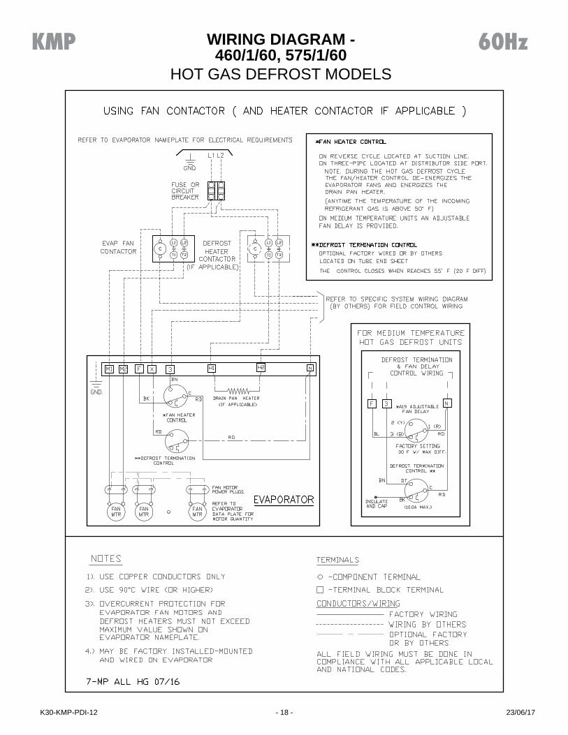
WIRING DIAGRAM - 460/1/60, 575/1/60
HOT GAS DEFROST MODELS
KMP 60Hz
23/06/17K30-KMP-PDI-12 - 18 -
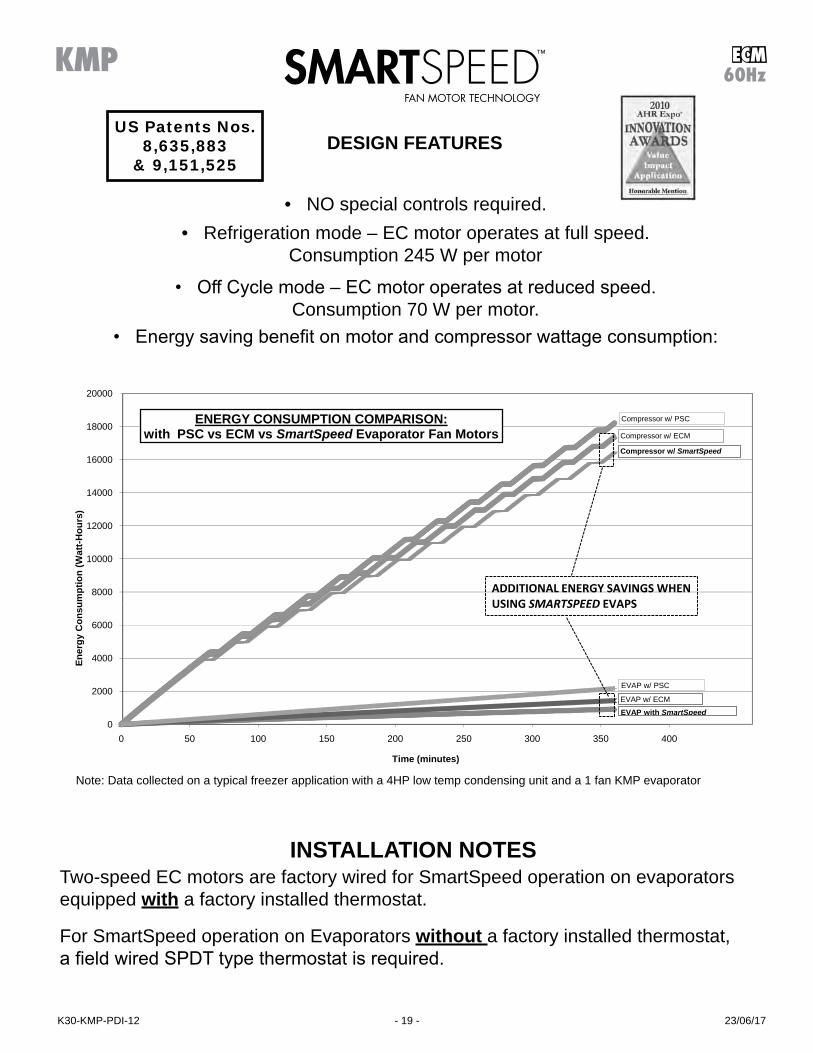
DESIGN FEATURES
ECM60Hz
• NO special controls required.• Refrigeration mode – EC motor operates at full speed.
Consumption 245 W per motor
• Off Cycle mode – EC motor operates at reduced speed. Consumption 70 W per motor.
• Energy saving benefit on motor and compressor wattage consumption:
INSTALLATION NOTESTwo-speed EC motors are factory wired for SmartSpeed operation on evaporators equipped with a factory installed thermostat.
For SmartSpeed operation on Evaporators without a factory installed thermostat,a field wired SPDT type thermostat is required.
Note: Data collected on a typical freezer application with a 4HP low temp condensing unit and a 1 fan KMP evaporator
8000
10000
12000
14000
16000
18000
20000
umpt
ion
(Wat
t-Hou
rs)
0
2000
4000
6000
0 50 100 150 200 250 300 350 400
Ener
gy C
onsu
Time (minutes)
ENERGY CONSUMPTION COMPARISON:with PSC vs ECM vs SmartSpeed Evaporator Fan Motors
Compressor w/ SmartSpeed
Compressor w/ PSC
Compressor w/ ECM
EVAP w/ PSC
EVAP w/ ECMEVAP with SmartSpeed
ADDITIONAL ENERGY SAVINGS WHEN USING SMARTSPEED EVAPS
US Patents Nos. 8,635,883
& 9,151,525
KMP
23/06/17K30-KMP-PDI-12 - 19 -

WIRING DIAGRAM - 115/1/60, 208-230/1/60OPTIONAL EC MOTORS with
AIR DEFROST MODELS
ECM60HzKMP
23/06/17K30-KMP-PDI-12 - 20 -

WIRING DIAGRAM - 208-230/1/60OPTIONAL EC MOTORS with
ELECTRIC DEFROST MODELS
ECM60HzKMP
23/06/17K30-KMP-PDI-12 - 21 -

WIRING DIAGRAM - 208-230/3/60OPTIONAL EC MOTORS with
ELECTRIC DEFROST MODELS - MULTIPLE EVAPORATORS
ECM60HzKMP
23/06/17K30-KMP-PDI-12 - 22 -

WIRING DIAGRAM - 460/1/60 w/ 230V CONTROLOPTIONAL EC MOTORS with 2 SPEED OPERATION
ELECTRIC DEFROST MODELS
ECM60HzKMP
23/06/17K30-KMP-PDI-12 - 23 -

WIRING DIAGRAM - 208-230/1/60OPTIONAL VARIABLE SPEED EC MOTORS
AIR DEFROST MODELS
ECM60HzKMP
23/06/17K30-KMP-PDI-12 - 24 -

WIRING DIAGRAM - 460/1/60 w/ 115V CONTROLOPTIONAL VARIABLE SPEED EC MOTORS
AIR DEFROST MODELS
ECM60HzKMP
23/06/17K30-KMP-PDI-12 - 25 -

WIRING DIAGRAM - 460/1/60 w/ 115V CONTROLOPTIONAL VARIABLE SPEED EC MOTORS
ELECTRIC DEFROST MODELS
ECM60HzKMP
23/06/17K30-KMP-PDI-12 - 26 -

DIMENSIONAL DATA
PIP
ING
C
OM
PAR
TME
NT
ELE
CTR
ICA
L C
OM
PAR
TME
NT
1 FAN MODEL TOP VIEW
ELE
CTR
ICA
L C
OM
PAR
TME
NT
ELE
CTR
ICA
L C
OM
PAR
TME
NT
ELE
CTR
ICA
L C
OM
PAR
TME
NT
PIP
ING
C
OM
PAR
TME
NT
PIP
ING
C
OM
PAR
TME
NT
PIP
ING
C
OM
PAR
TME
NT
4 FAN MODEL TOP VIEW
3 FAN MODEL TOP VIEW
2 FAN MODEL TOP VIEW
136 1/4(3461)
118 1/4(3004)
84 1/4(2140)
30(762)
36(914)
34(864)
8 1/8(206)
8 1/8(206)
30(762)
34(864)
8 1/8(206)
8 1/8(206)
50 1/4(1276)
16 3
/4(4
25)
MTG
SLO
TS
34(864)
36(914)
6 1/8(156)
32(813)
30(762)
36(914)
6 1/8(156)
6 1/8(156)
5 3/4(144)
11 7/8(302)
15(387)
24(608)
MINIMUM CLEARANCE
6 1/8(156)
27 3
/4(7
04)
16 3
/4(4
25)
MTG
SLO
TS
16 3
/4(4
25)
MTG
SLO
TS
16 3
/4(4
25)
MTG
SLO
TS
3/4 NPT ( 14 NPS )DRAIN CONNECTION
ALL MODELS AIR THROW :APPROX. 75 FEET (23 METERS)IN OPEN SPACE
KMP 60Hz
23/06/17K30-KMP-PDI-12 - 27 -

DIMENSIONAL DATA / SPECIFICATIONS
Medium Temperature Air and Electric Defrost Models
Low Temperature Electric Defrost Models
Hot Gas Defrost Models
MODEL KMP NO. OF FANS SUCTION CONNECTION (ID) SWEAT DISTRIBUTOR INLET SIZE118M# 1 7/8 5/8122M# 1 1 1/8 5/8228M# 2 1 1/8 5/8236M# 2 1 3/8 7/8245M# 2 1 3/8 1-1/8355M# 3 1 5/8 1-1/8368M# 3 1 5/8 1-1/8480M# 4 1 5/8 1-1/8488M# 4 1 5/8 1-1/8
# = A or E. Refer to Nomenclature for details
MODEL KMP NO. OF FANS SUCTION CONNECTION (ID) SWEAT DISTRIBUTOR INLET SIZE116LE 1 1 1/8 7/8119LE 1 1 1/8 7/8225LE 2 1 3/8 7/8232LE 2 1 3/8 1-1/8240LE 2 1 5/8 1-1/8348LE 3 1 5/8 1-5/8356LE 3 1 5/8 1-5/8471LE 4 2 1/8 1-5/8113VE 1 1 1/8 7/8117VE 1 1 1/8 7/8222VE 2 1 3/8 7/8228VE 2 1 3/8 1-1/8234VE 2 1 5/8 1-1/8339VE 3 1 5/8 1-1/8350VE 3 1 5/8 1-1/8459VE 4 1 5/8 1-5/8
MODEL
KMP
NO. OFFANS
SUCTION CONNECTION
(ID) SWEAT
REVERSE CYCLE DEFROST 3 PIPE DEFROST HOT GAS DRAIN PAN LOOP CONNECTION
(OD) SWEATDISTRIBUTOR
INLETSIZE (OD) SWEAT
SIDE PORT CONNECTION(OD) SWEAT
DISTRIBUTORINLET
SIZE (OD) SWEAT
SIDE PORT CONNECTION(OD) SWEAT
118M^ 1 7/8 5/8 1/2 5/8 1/2 7/8122M^ 1 1 1/8 7/8 1/2 7/8 1/2 7/8228M^ 2 1 1/8 7/8 1/2 7/8 1/2 7/8236M^ 2 1 3/8 7/8 1/2 7/8 1/2 7/8245M^ 2 1 3/8 1 1/8 5/8 1 1/8 5/8 7/8355M^ 3 1 5/8 1 1/8 5/8 1 1/8 5/8 1 1/8368M^ 3 1 5/8 1 3/8 7/8 1 3/8 7/8 1 1/8480M^ 4 1 5/8 1 3/8 7/8 1 5/8 7/8 1 3/8488M^ 4 1 5/8 1 3/8 7/8 1 5/8 7/8 1 3/8116L^ 1 1 1/8 7/8 1/2 7/8 1/2 7/8119L^ 1 1 1/8 7/8 1/2 7/8 1/2 7/8225L^ 2 1 3/8 7/8 1/2 1 1/8 5/8 7/8232L^ 2 1 3/8 1 1/8 5/8 1 3/8 7/8 7/8240L^ 2 1 5/8 1 3/8 7/8 1 3/8 7/8 7/8348L^ 3 1 5/8 1 5/8 1 1/8 1 5/8 1 1/8 1 1/8356L^ 3 1 5/8 1 5/8 1 1/8 1 5/8 1 1/8 1 1/8471L^ 4 2 1/8 1 5/8 1 1/8 1 5/8 1 1/8 1 3/8113V^ 1 1 1/8 7/8 1/2 7/8 1/2 7/8117V^ 1 1 1/8 7/8 1/2 7/8 1/2 7/8222V^ 2 1 3/8 7/8 1/2 1 1/8 5/8 7/8228V^ 2 1 3/8 1 1/8 5/8 1 1/8 5/8 7/8234V^ 2 1 5/8 1 3/8 7/8 1 3/8 7/8 7/8339V^ 3 1 5/8 1 1/8 5/8 1 3/8 7/8 1 1/8350V^ 3 1 5/8 1 3/8 7/8 1 5/8 7/8 1 1/8459V^ 4 1 5/8 1 5/8 1 1/8 1 5/8 1 1/8 1 3/8
^ = T, H, G, or R. Refer to Nomenclature for details
KMP 60Hz
23/06/17K30-KMP-PDI-12 - 28 -

SHIPPING WEIGHTS
AIR DEFROST ELECTRIC DEFROST HOT GAS DEFROST
MODEL KMP
SHIPPING WEIGHT MODEL
KMP
SHIPPING WEIGHT
WITH HOT GAS LOOP WITH ELECTRIC HEATER PAN
MODEL KMPSHIPPING WEIGHT MODEL KMP
SHIPPING WEIGHTLB. (kg.) LB. (kg.) LB. (kg.) LB. (kg.)
118MA 154 (70) 118ME 163 (74) 118MH 118MR 160 (72) 118MG 118MT 156 (71)122MA 161 (73) 122ME 171 (77) 122MH 122MR 168 (76) 122MG 122MT 164 (74)228MA 224 (102) 228ME 241 (109) 228MH 228MR 239 (108) 228MG 228MT 228 (104)236MA 240 (109) 236ME 257 (116) 236MH 236MR 255 (116) 236MG 236MT 244 (111)245MA 254 (115) 245ME 270 (123) 245MH 245MR 269 (122) 245MG 245MT 258 (117)355MA 326 (148) 355ME 349 (158) 355MH 355MR 353 (160) 355MG 355MT 332 (150)368MA 349 (158) 368ME 372 (169) 368MH 368MR 376 (170) 368MG 368MT 355 (161)480MA 414 (188) 480ME 441 (200) 480MH 480MR 453 (205) 480MG 480MT 421 (191)488MA 433 (196) 488ME 460 (209) 488MH 488MR 472 (214) 488MG 488MT 440 (200)
116LE 164 (74) 116LH 116LR 161 (73) 116LG 116LT 157 (71)119LE 171 (78) 119LH 119LR 168 (76) 119LG 119LT 164 (75)225LE 243 (110) 225LH 225LR 241 (109) 225LG 225LT 230 (104)232LE 257 (117) 232LH 232LR 256 (116) 232LG 232LT 245 (111)240LE 273 (124) 240LH 240LR 272 (123) 240LG 240LT 261 (119)348LE 352 (160) 348LH 348LR 356 (162) 348LG 348LT 335 (152)356LE 377 (171) 356LH 356LR 382 (173) 356LG 356LT 360 (164)471LE 443 (201) 471LH 471LR 455 (206) 471LG 471LT 423 (192)113VE 160 (73) 113VH 113VR 157 (71) 113VG 113VT 153 (70)117VE 166 (75) 117VH 117VR 163 (74) 117VG 117VT 160 (72)222VE 238 (108) 222VH 222VR 236 (107) 222VG 222VT 226 (102)228VE 250 (113) 228VH 228VR 249 (113) 228VG 228VT 238 (108)234VE 263 (119) 234VH 234VR 262 (119) 234VG 234VT 252 (114)339VE 346 (157) 339VH 339VR 350 (159) 339VG 339VT 329 (149)350VE 362 (164) 350VH 350VR 367 (166) 350VG 350VT 346 (157)459VE 425 (193) 459VH 459VR 438 (198) 459VG 459VT 406 (184)
KMP 60Hz
23/06/17K30-KMP-PDI-12 - 29 -

FACTORY INSTALLED DISTRIBUTOR NOZZLES
MODEL
KMP
R404A R507
R448AR407AR407C
R22 118MG 118MR J-1 1/2 J-1122MG 122MR G-2 G-1 1/2228MG 228MR G-2 1/2 G-1 1/2236MG 236MR G-3 G-2245MG 245MR E-4 E-2-1/2355MG 355MR E-5 E-3368MG 368MR C-6 C-4480MG 480MR A-8 C-5488MG 488MR A-10 C-5
Medium Temperature Reverse Cycle Defrost Models
MODEL
KMP
R404A R507
R448AR407AR407C
R22 118MT 118MH J-1 1/2 J-1122MT 122MH G-2 G-1 1/2228MT 228MH G-2 1/2 G-1 1/2236MT 236MH G-3 G-2245MT 245MH E-4 E-2-1/2355MT 355MH E-5 E-3368MT 368MH C-6 C-4480MT 480MH C-8 C-5488MT 488MH C-10 C-5
Medium Temperature 3 Pipe Defrost Models
MODEL
KMP
R448AR407AR404A R507
116LG 116LR G-2-1/2119LG 119LR G-3225LG 225LR E-4232LG 232LR C-5240LG 240LR C-6348LG 348LR A-8356LG 356LR A-10471LG 471LR A-12
MODEL
KMP
R448AR407AR404A R507
113VG 113VR G-2117VG 117VR G-2-1/2222VG 222VR E-3228VG 228VR E-4234VG 234VR C-5339VG 339VR C-6350VG 350VR A-8459VG 459VR A-10
Low Temperature Reverse Cycle Defrost Models
MODEL
KMP
R448AR407AR404A R507
116LT 116LH G-2-1/2119LT 119LH G-3225LT 225LH G-4232LT 232LH E-5240LT 240LH C-6348LT 348LH A-8356LT 356LH A-10471LT 471LH A-12
MODEL
KMP
R448AR407AR404A R507
113VT 113VH G-2117VT 117VH G-2-1/2222VT 222VH G-3228VT 228VH E-4234VT 234VH C-5339VT 339VH E-6350VT 350VH C-8459VT 459VH A-10
Low Temperature 3 Pipe Defrost Models
MODEL KMP ALL REFRIGERANTS118M#-S2A J1-1/2122M#-S2A J2228M#-S2A J2-1/2236M#-S2A G3245M#-S2A E4355M#-S2A E5368M#-S2A E6480M#-S2A E10488M#-S2A E12
# = A or E. Refer to Nomenclature for details
Medium Temperature Air and Electric Defrost Models
MODEL KMP ALL REFRIGERANTS116LE-S2A G2-1/2119LE-S2A G3225LE-S2A G4232LE-S2A E5240LE-S2A E6348LE-S2A A8356LE-S2A A10471LE-S2A A12113VE-S2A G2-1/2117VE-S2A G2-1/2222VE-S2A G3228VE-S2A E4234VE-S2A E5339VE-S2A E6350VE-S2A E8459VE-S2A A10
Low Temperature Electric Defrost Models
KMP 60Hz
For R449A, use R448A data. For R449A, use R448A data.
For R449A, use R448A data. For R449A, use R448A data.
23/06/17K30-KMP-PDI-12 - 30 -

RECOMMENDED EXPANSION VALVE SELECTIONS
MEDIUM TEMPERATURE MODELS
Above selections based on: 1) 100°F (38°C) vapor free liquid entering expansion valve 2) 110°F (43°C) Condensing temperature 3) 8 -12°F (4.4 -6.7°C) evaporator TD
MODEL
KMP
R404A R507
R448AR407A R407C
R22 R134a
118M HFESC - 1-1/4 - SC HFESC - 1-1/2 - HC HFESC - 1-1/2 - MC122M HFESC - 1-1/2 - SC HFESC - 2 - HC HFESC - 1-3/4- MC228M HFESC - 2 - SC HFESC - 2 - HC HFESC - 1-3/4 - MC236M HFESC - 3-1/2 - SC HFESC - 2-1/2 - HC HFESC - 2-1/2 - MC245M HFESC - 3-1/2 - SC HFESC - 3 - HC HFESC - 4 - MC355M HFESC - 3-1/2 - SC HFESC - 5-1/2 - HC HFESC - 4 - MC368M HFESC - 5 - SC HFESC - 5-1/2 - HC HFESC - 6- MC480M HFESC - 7 - SC HFESC -5-1/2 - HC HFESC - 6 - MC488M HFESC - 7 - SC HFESC - 8 - HC HFESC - 7-1/2 - MC
If correct nozzle is not available, the proper orifice size can be drilled in the
field using the following chart
NOZZLEORIFICE No.
DRILL SIZE
IN.
1/2 .070
3/4 .086
1 .0995
1-1/2 .120
2 .1406
2-1/2 .157
3 .172
4 .199
5 .211
6 .242
8 .266
10 .281
MODEL
KMP
R404A R507
R448AR407AR407C
R22
R134a
118M TUAE-07 TUAE-06 TUAE-07122M TUAE-08 TUAE-07 TUAE-08228M TUAE-09 TUAE-08 TUAE-09236M TUAE-09 TUAE-08 TUAE-09245M TCAE-2 TUAE-09 TCAE-2355M TCAE-3 TCAE-1 TCAE-3368M TDEBS 5.8 TCAE-2 TDEBN 8.5480M TDEBS 8.0 TCAE-3 TDEBN 9.6488M TDEBS 8.0 TCAE-3 TDEBN 9.6
DANFOSS
MODEL
KMP
R404A R507
R448AR407AR407C
R22
R134a
118M SBFSE-B-C SBFVE-A-C SBFJE-B-C122M SBFSE-B-C SBFVE-B-C SBFJE-B-C228M SBFSE-C-C SBFVE-B-C SJE- 2 1/2-C236M SSE-3-C SBFVE-C-C SJE- 2 1/2-C245M SSE-4-C SVE-4-C SJE-3-C355M SSE-6-C SVE-4-C EBSJE-5-C368M EBSSE-6-C SVE-5-C SJE-5-C480M SSE-7-C EBSVE-8-C SJE-6-C488M EBSSE-7 1/2-C SVE-8-C EBSJE-7-C
* For R507, refrigerant code for Sporlan expansion valve will be “P” instead of “S” . i.e.: “SBFSE” becomes “SBFPE”
SPORLAN* ALCO
KMP 60Hz
For R449A, use R448A data.
For R449A, use R448A data.
For R449A, use R448A data.
23/06/17K30-KMP-PDI-12 - 31 -

RECOMMENDED EXPANSION VALVE SELECTIONS
LOW TEMPERATURE MODELS
Above selections based on: 1) 100°F (38°C) vapor free liquid entering expansion valve 2) 110°F (43°C) Condensing temperature 3) 8 -12°F (4.4 -6.7°C) evaporator TD
SPORLAN - R404A MODEL KMP 0° F (-18° C) EVAP. -10° F (-23° C) EVAP. -20° F (-29° C) EVAP. -30° F (-34° C) EVAP. -40° F (-40° C) EVAP.
116L SBFSE-B-C SBFSE-B-ZP SBFSE-B-ZP SBFSE-C-ZP SBFSE-C-ZP119L SBFSE-B-C SBFSE-B-ZP SBFSE-C-ZP SBFSE-C-ZP SBFSE-C-ZP225L SSE-3-C SSE-3-ZP SSE-3-ZP SSE-4-ZP SSE-4-ZP232L SSE-4-C SSE-4-ZP SSE-4-ZP SSE-4-ZP SSE-4-ZP240L SSE-4-C SSE-4-ZP EBSSE-6-ZP EBSSE-6-ZP EBSSE-6-ZP348L SSE-6-C SSE-6-ZP SSE-6-ZP SSE-7-ZP SSE-7-ZP356L SSE-7-C SSE-7-ZP SSE-7-ZP OSE-9-ZP OSE-9-ZP471L OSE-9-C OSE-12-ZP OSE-12-ZP OSE-12-ZP OSE-12-ZP113V SBFSE-B-C SBFSE-B-ZP SBFSE-B-ZP SBFSE-B-ZP SBFSE-B-ZP117V SBFSE-B-C SBFSE-B-ZP SBFSE-C-ZP SBFSE-C-ZP SBFSE-C-ZP222V SBFSE-C-C SBFSE-C-ZP SBFSE-C-ZP SBFSE-C-ZP SBFSE-C-ZP228V SSE-3-C SSE-3-ZP SSE-3-ZP SSE-4-ZP SSE-4-ZP234V SSE-4-C SSE-4-ZP SSE-4-ZP SSE-6-ZP SSE-6-ZP339V SSE-4-C EBSSE-6-ZP EBSSE-6-ZP EBSSE-6-ZP EBSSE-6-ZP350V EBSSE-6-C EBSSE-7-1/2-ZP EBSSE-7-1/2-ZP EBSSE-7-1/2-ZP EBSSE-7-1/2-ZP459V SSE-7-C SSE-7-ZP SSE-7-ZP OSE-9-ZP OSE-9-ZP
* For R507, refrigerant code for Sporlan expansion valve will be “P” instead of “S” . i.e.: “SBFSE” becomes “SBFPE”
SPORLAN - R407A R448AMODEL KMP 0° F (-18° C) EVAP. -10° F (-23° C) EVAP. -20° F (-29° C) EVAP. -30° F (-34° C) EVAP. -40° F (-40° C) EVAP.
116L SBFVE-A-C SBFVE-B-ZP40 SBFVE-B-ZP40 SBFVE-B-ZP40 SBFVE-B-ZP40119L SBFVE-B-C SBFVE-B-ZP40 SBFVE-B-ZP40 SBFVE-B-ZP40 SBFVE-C-ZP40225L SVE-3-C SVE-3-ZP40 SVE-4-ZP40 SVE-4-ZP40 SVE-5-ZP40232L SVE-3-C SVE-4-ZP40 SVE-4-ZP40 SVE-5-ZP40 SVE-8-ZP40240L SVE-4-C SVE-5-ZP40 SVE-5-ZP40 SVE-8-ZP40 SVE-8-ZP40348L SVE-4-C SVE-8-ZP40 SVE-8-ZP40 SVE-10-ZP40 SVE-10-ZP40356L SVE-5-C SVE-8-ZP40 SVE-10-ZP40 SVE-10-ZP40 OVE-15-ZP40471L SVE-8-C SVE-10-ZP40 OVE-15-ZP40 OVE-15-ZP40 OVE-15-ZP40113V SBFVE-A-C SBFVE-A-ZP40 SBFVE-B-ZP40 SBFVE-B-ZP40 SBFVE-B-ZP40117V SBFVE-A-C SBFVE-B-ZP40 SBFVE-B-ZP40 SBFVE-B-ZP40 SBFVE-B-ZP40222V SBFVE-B-C SVE-3-ZP40 SVE-3-ZP40 SVE-4-ZP40 SVE-4-ZP40228V SVE-3-C SVE-4-ZP40 SVE-4-ZP40 SVE-4-ZP40 SVE-5-ZP40234V SVE-3-C SVE-4-ZP40 SVE-5-ZP40 SVE-5-ZP40 SVE-8-ZP40339V SVE-4-C SVE-5-ZP40 SVE-5-ZP40 SVE-8-ZP40 SVE-8-ZP40350V SVE-5-C SVE-8-ZP40 SVE-8-ZP40 SVE-10-ZP40 SVE-10-ZP40459V SVE-8-C SVE-8-ZP40 SVE-10-ZP40 SVE-10-ZP40 OVE-15-ZP40
KMP 60Hz
For R449A, use R448A data.
23/06/17K30-KMP-PDI-12 - 32 -

INSTALLATION INSTRUCTIONSINSTALLATIONThe installation and start-up of evaporators should only be performed by qualified refrigeration mechanics. This equip-ment should be installed in accordance with all applicable codes, ordinances and local by-laws.
INSPECTIONInspect all equipment before unpacking for visible signs of damage or loss. Check shipping list against material received to ensure shipment is complete.IMPORTANT: Remember, you, the consignee, must make any claim necessary against the transportation company. Shipping damage or missing parts, when discovered at the outset, will prevent later unnecessary and costly delays. If damage or loss during transport is evident, make claim to carrier, as this will be their responsibility, not the manufacturer’s. Should carton be damaged, but damage to equipment is not obvious, a claim should be filed for “concealed damage” with the carrier.IMPORTANT: The electrical characteristics of the unit should be checked at this time to make sure they corre-spond to those ordered and to electrical poweravailable at the job site.Save all shipping papers, tags and instruction sheets for reference by installer and owner.
APPLICATIONMP evaporators are designed for walk-in cooler, walk-in refrigerated warehouse and food processing plant applications used with a wide variety of refrigerants. For room temperatures above 35°F (2°C) AND evaporating temperatures above 26°F (-3°C), positive defrosting means (with electric or hot gas) may not be required, otherwise, electric defrost or hot gas defrost models should be used. Electric defrost models come with defrost termination and fan delay as standard to control the defrost cycle termi-nation and fan delay, while defrost initiation means (e.g. defrost timer) is not included.
For other types of refrigerant, contact factory.
The coil must not be exposed to any abnormal atmospheric or acidic environments. This may result in corrosion to the cabinet and possible coil failure (leaks). (Consult manufacturer for optional baked on phenolic protective coatings).
LOCATIONThe unit location in the room should be selected to ensure uniform air distribution throughout the entire space to be refrigerated. Be sure that the product does not obstruct the free circulation of air. Allow a minimum of 24” clearance at each end. Do not locate evaporators over doors. Con-sideration should be given to the coil location in order to minimize the piping run length to the condensing unit and floor drain.
EXPANSION VALVE (TXV) SELECTIONAll units require the use of an externally equalized expansion valve. (A 1/4” (6 mm) O.D. equalizer line has been provided on the coil) TX valves should not be se-lected strictly by their nominal ton rating. (This rating is
based at a specific pressure differential and entering liquid temperature). Since applications will differ it is suggested the following selection procedure be followed.
1. Determine actual evaporator capacity. The nominal rating is based at 10°F T.D. (5 .6°C) (Entering Air Temp. minus Evap. Temp.) Note that a higher / lower operating T.D.will increase / decrease this capacity rating by their direct ratio within a range of 8 to 12°F (4 .4 to 8.3°C) T.D.
2. Determine the pressure drop across the valve by subtracting the evaporating pressure and distributor pressure drop from the high side liquid pressure. The distributor pressure drop is typically in the range of 20 to 35 psig (1.4 to 2.4 bar) depending on the type of refrigerant and operating conditions.
3. Estimate entering liquid temperature. Temperatures lower than 100°F (38 °C) increase valve capacity ratings. Refer to valve manufacturer’s specs for details.
4. Select valve from the valve manufacturer selection charts or software for the appropriate refrigerant, evaporating temp and pressure drop.
For best performance, the outlet of the expansion valve should be installed directly to the distributor body. If this is not possible, a straight tube up to 12 inches may be used for the connection.
Locate the expansion valve bulb on a horizontal length of suction line preferably 3 to 6 inches from the suction header. Locate the bulb at 4 or 8 clock position and insu-late with a waterproof type of insulation. Clamp the bulb to ensure 100% contact of the bulb with the suction line.
Ensure appropriate nozzle has been installed in the dis-tributor before installing valve. After following the manu-facturer’s installation instructions and after the room has reached the desired temperature the valve superheat should be checked. This will confirm that the evaporator is operating properly and performing to maximum efficiency. The superheat should be around 60 to 80% of T.D. Too high or low a superheat will result in unsatisfactory system performance and possible compressor problems.
NOZZLE INSTALLATIONFor common applications (Medium temp. R404A/R22/ R407A/R448A 8 to 12°F (4 .4 to 6.7°C) T.D.); (Low temp. R404A/R407A/R448A 8 to 12°F (4 .4 to 6.7°C) T.D.) the nozzle for all models has been factory installed. For other applications, refer to nozzle manufacturer’s selection guide. To replace a nozzle, the nozzle retainer clip (in distributor) must be removed before inserting nozzle. Re-install clip ensuring nozzle is properly in place. A small nozzle can be drilled larger using the drill size listed in table on page 31. Ensure the hole must be accurately centered and smooth. A lathe is preferred for the drilling.
KMP 60Hz
23/06/17K30-KMP-PDI-12 - 33 -
INSTALLATION INSTRUCTIONS (cont’d)
MOUNTINGRefer to dimensional drawing for recommended mounting arrangements. Ensure adequate clearance is provided be-hind the coil as well as each end. The evaporators may be mounted flush with ceiling with bolts, or hanging down with rod hangers. When using rod hangers, allow adequate space between the top of the unit and the ceiling for cleaning to comply with NSF Standard 7.Ensure that the ceiling is level since the drain pan has been sloped for drainage during the defrost cycle.
DRAIN LINEThe drain line should be run from the drain connection, sloping at least 1” (25 mm) per foot and should have the size at least as large as the drain connection. A trap in a warm area outside the room must be provided to allow proper draining through the tubing. Connection should be made to proper drainage facilities that comply with local regulations.
To prevent freeze-up when the temperature of the refrigerated space is 35oF (2 °C) or lower, the drain line should be heated along its run inside the cold room. The heated drain line should be insulated. It is recommended that the heater be energized at all times. A heat input of 20 watts per foot in a 28°F (-2°C) room and 30 watts per foot for -20°F (-29°C) rooms, is satisfactory. Drain line heat-ers are not required for constant room temperature above 35°F (2°C).
Always trap evaporator drain line individually to prevent vapor migration.
Ensure that the drain line has sufficient slope for proper drainage (prevention of ice build up/blockage in pan).
PIPINGRefrigeration grade piping must be used for all field refrigeration piping. Refrigerant line sizes are important and may not be the same size as the coil connections. Consult ASHRAE handbook or other similar reference book for proper line sizing.
Refrigerant piping and control system should be designed to prevent possible liquid slugging (from oil or refrigerant) of the compressors on start-up after the defrost cycle. Also, it should prevent oil logging and minimize refrigerant pressure drop.
For hot gas models, see pages 38 to 39 for recommended piping.
WIRINGWire system in accordance with governing standards and local codes. See data and wiring diagrams on pages 4 to 29 for typical wiring arrangement. Electrical wiring is to be sized in accordance with minimum circuit ampacity rating (MCA). Size fuses used must not exceed the Maximum Fuse Size ratings.
For ease of identifying the proper wiring terminal, unit wiring is color coded and terminal block connections are identified.
When fan delay thermostats (combination fan delay and defrost termination) are installed, on start-up, the fans do not operate until the coil temperature is reduced to ap-proximately 25oF (-4°C). It is normal for the fans to cycle a few times until the room temperature is brought down. At higher evaporating temperatures this control may not close and therefore should either be by-passed temporarily or replaced with an adjustable type. (set for a higher tem-perature cut-in point).
MAINTENANCEThe unit should be periodically inspected for any dirt or ice build-up on the fin surface and cleaned if necessary with a soft whisk or brush. Also ensure coils inner (and outer) drain pans do not have any ice build-up from improper defrost operation. When replacing heater elements first remove heater retainer brackets and heater clips.
SYSTEM CHECK
Before Start-Up:1. All wiring should be in accordance with local codes.2. Refrigerant lines should be properly sized.3. All systems preferably include a liqud line solenoid valve at immediately up stream of the expansion valve.4. Thorough evacuation and dehydration has been performed.5. The suction, discharge, and receiver service valves must be open.6. The system preferably include a liquid line filter drier moisture indicator and suction filter.7. Pour enough water into the drain pan to allow a good check on drainage and seal the trap.
After Start-Up:1. Check the oil level to be sure the oil charge is correct.2. On initial start up the fans do not start until coil temperature is pulled down to approximately 25°F (-4°C) on the coil. Also, it is normal for the fan to cycle a few times until the room temperature is pulled down.3. If necessary, temporarily by-pass fan delay control (to run fans until room temp is lowered).4. Be sure that the expansion valve is properly set to provide the correct amount of superheat.5. After the box temperature is close to reaching the desired temperature, the evaporator superheat must be checked and adjustment made if necessary. In general, evaporators running with a TD of 10°F (5.6°C) should have a superheat reading of 6° to 8°F (3.3°C to 4.4°C). For evaporators with another T.D., the general rule is that the superheat should be around 60 to 80% of T.D.6. Heavy moisture loads are usually encountered when starting the system for the first time. This may cause a rapid build-up of frost on the evaporator. During the initial pull down, we suggest that the frost build-up be watched and defrosted manually as required. 7. Observe that the system goes through at least one complete DEFROST CYCLE.
KMP 60Hz
23/06/17K30-KMP-PDI-12 - 34 -

HOT GAS PIPING SCHEMATICSSTANDARD CONFIGURATIONS
Refer to Nomenclature for detailsWITH HOT GAS DRAIN PAN LOOP
WITH CHECK VALVE LOOSE
HOT GASLEAVING
DEFROST LOOPHOT GAS DRAIN PAN
VALVECHECK
REVERSE CYCLE DEFROST
EVAPORATOR COIL DISTRIBUTOR
STD-RFACTORY PIPING
HOT GASENTERING
LEAVINGHOT GAS
WITH CHECK VALVE LOOSE
REVERSE CYCLE DEFROST
ELECTRIC DRAIN PAN HEATER
EVAPORATOR COIL DISTRIBUTOR
STD-GFACTORY PIPING
CHECKVALVE
WITH DRAIN PAN HEATER
WITH CHECK VALVE LOOSEWITH HOT GAS DRAIN PAN LOOP
STD-HDEFROST LOOP
HOT GAS DRAIN PAN
HOT GASLEAVING
VALVECHECK
EVAPORATOR COIL
3-PIPE DEFROST
DISTRIBUTOR
FACTORY PIPING
ENTERINGHOT GAS
WITH CHECK VALVE LOOSE
VALVECHECK
STD-T
EVAPORATOR COIL
ELECTRIC DRAIN PAN HEATER
3-PIPE DEFROST
ENTERINGHOT GAS
DISTRIBUTOR
LEAVINGHOT GAS
FACTORY PIPING
WITH DRAIN PAN HEATER
Standard Offering: All ModelsCheck Valve is included with the coil shipped loose as it is a must have component for system operation.
Check Valve & TXV - See next page (OPT 1)When a TXV is ordered with a HG defrost coil: Its only option will be Factory Installed. The bypass check valve will be factory installed as well as part of the same option. • Reverse Cycle PanHeater (G Models) when ordered with TXV & Check Valve: o TXV, Check Valve and bypass Tee are factory installed • Reverse Cycle PanLoop (R Models) when ordered with TXV & Check Valve: o TXV, Check Valve and bypass Tee are factory installed • 3-Pipe PanHeater (T Models) when ordered with TXV & Check Valve: o TXV and Check Valve are factory installed • 3-Pipe PanLoop (H Models) when ordered with TXV & Check Valve: o TXV and Check Valve are factory installed
KMP 60Hz
23/06/17K30-KMP-PDI-12 - 35 -

HOT GAS PIPING SCHEMATICSOPTIONAL CONFIGURATIONS
Refer to Nomenclature for details
COMPLETE ASSY PROVIDED WHEN TXV IS MTD
WITH HOT GAS DRAIN PAN LOOPCHECK VALVE MOUNTED
CHECK
DEFROST LOOPHOT GAS DRAIN PAN
VALVE
REVERSE CYCLE DEFROST
EVAPORATOR COIL DISTRIBUTORTXV
OPT1
FACTORY PIPING
R
LEAVINGHOT GAS
CHECK VALVE MOUNTEDCOMPLETE ASSY PROVIDED WHEN TXV IS MTD
REVERSE CYCLE DEFROST
ELECTRIC DRAIN PAN HEATER
EVAPORATOR COIL DISTRIBUTOR
CHECKVALVE
TXV
GOPT1
FACTORY PIPING
LEAVINGHOT GAS
WITH DRAIN PAN HEATER
ASSEMBLED OUTSIDE CABINET
WITH HOT GAS DRAIN PAN LOOPCHECK VALVE MOUNTED
COMPLETE ASSY PROVIDED WHEN TXV IS MTD
HOT GAS DRAIN PANDEFROST LOOP & SHIPPED SEPARATELY
REVERSE CYCLE DEFROST
EVAPORATOR COIL
CHECKVALVE
DISTRIBUTORTXV
R
FACTORY PIPINGFIELD PIPING
ENTERINGHOT GAS
OPT2LEAVINGHOT GAS
CHECKVALVE
VALVE
OPT1HOT GAS DRAIN PAN
DEFROST LOOP
(SUCTION LINE)
LEAVINGHOT GAS
ENTERINGHOT GAS
FACTORY PIPING
H
WITH HOT GAS DRAIN PAN LOOP
WITH TXV BY OTHERS OR FACTORY INSTALLEDWITH CHECK VALVE MTD. & CONNECTED TO LOOP
3 PIPE DEFROST
EVAPORATOR COIL DISTRIBUTOR
TXV
CHECK
OPT1
WITH CHECK VALVE MOUNTEDWITH TXV BY OTHERS OR FACTORY INSTALLED
EVAPORATOR COIL
3 PIPE DEFROST
ELECTRIC DRAIN PAN HEATER
HOT GAS(SUCTION LINE)
DISTRIBUTOR
LEAVING
CHECKVALVE
TXV
FACTORY PIPING
T
ENTERINGHOT GAS
Drain pan Loop Kit - See below (OPT 2)Drain pan loop kit is an assembly that is fully assembled and shipped loose for field installation outside the cabinet. Two check valves are included, depending on the model size, one or both are factory installed. • Reverse Cycle PanLoop (R Models) when ordered with TXV & Check Valve: o Suction line piping shipped as a pre-piped assembly for field installation
Solenoid ValveSolenoid valves are available as a shipped loose item due to limited space inside the cabinet
KMP 60Hz
23/06/17K30-KMP-PDI-12 - 36 -

GLYCOL FLUID AIR COOLER DATA
The above capacities were rated based on 30% Propylene Glycol, 25°F (-4°C) glycol entering temperature and 35°F (2°C) air entering term-perature with glycol flow rate listed. For all other conditions, please use “Pi-Coil” software (contact factory).
MODEL
KMP
NO. OF
FANS
CAPACITY * - 15 USGPM (.095 L/S), 3/8” TUBING CAPACITY * - 40 USGPM (.25 L/S), 1/2” TUBING
AIR FLOWBTU/H (WATTS) P.D.
(FT. H20)P.D.
(kPa)
CONN. SIZE
(IN/OUT)
AIR FLOWBTU/H (WATTS) P.D.
(FT. H20)P.D.
(kPa)
CONN. SIZE (IN/
OUT)CFM (L/S) CFM (L/S)
118W 1 3430 (1620) 8980 (2630) 4.8 (14.3) 1 3/8 3150 (1486) 11100 (3250) 7.8 (23.3) 1 5/8122W 1 3240 (1530) 10400 (3050) 2.8 (8.4) 1 3/8 2990 (1411) 12700 (3720) 4.6 (13.7) 1 5/8236W 2 6870 (3240) 15400 (4510) 8.1 (24.2) 1 3/8 6300 (2973) 21700 (6360) 13 (37.4) 1 5/8245W 2 6480 (3060) 18100 (5300) 4.8 (14.3) 1 3/8 5980 (2822) 22800 (6680) 7.4 (22.1) 1 5/8355W 3 10300 (4860) 20700 (6060) 11 (33.2) 1 3/8 9480 (4474) 31900 (9340) 17 (51.7) 1 5/8368W 3 9720 (4590) 24200 (7090) 6.7 (20.0) 1 3/8 8940 (4219) 31600 (9260) 10 (31.1) 1 5/8480W 4 13000 (6140) 27700 (8110) 7.6 (22.7) 1 3/8 11990 (5658) 37500 (11000) 12 (35.3) 1 5/8
KMP 60Hz
23/06/17K30-KMP-PDI-12 - 37 -

System
Model Number Date of Start-Up
Serial Number Service Contractor
Refrigerant Phone
Electrical Supply E-mail
PROJECT INFORMATIONKMP 60Hz
23/06/17K30-KMP-PDI-12 - 38 -

KMP 60HzPRODUCT SUPPORT RESOURCES
web: k-rp.com/kmpemail: [email protected]
call: 1-844-893-3222 x520
email: [email protected]: 1-844-893-3222 x529
web: k-rp.com/parts email: [email protected]
call: 1-844-893-3222 x501
web: k-rp.com/warranty email: [email protected]: 1-844-893-3222 x501
email: [email protected]: 1-844-893-3222 x501
email: [email protected]: 1-844-893-3222 x503
23/06/17K30-KMP-PDI-12 - 39 -

“AS BUILT” SERVICE PARTS LIST
Service Parts ListLabel
To Be AttachedHERE
Due to the manufacturer’s policy of continuous product improvement, we reserve the right to make changes without notice.
159 ROY BLVD., BRANTFORD, ON, N3R 7K1
NATIONAL REFRIGERATION & AIR CONDITIONING CANADA CORP.
1-800-463-9517 (519) 751-0444 www.k-rp.com [email protected] fax: (519) 753-1140 COMPONENT
23/06/17