medium-high pressure control group (mhpc) installation · 2020-01-02 · medium-high pressure...
TRANSCRIPT
1
MHPC FCD LFENIM0006-00 AQ – 06/16
Experience In Motion
Installation Operation
Maintenance
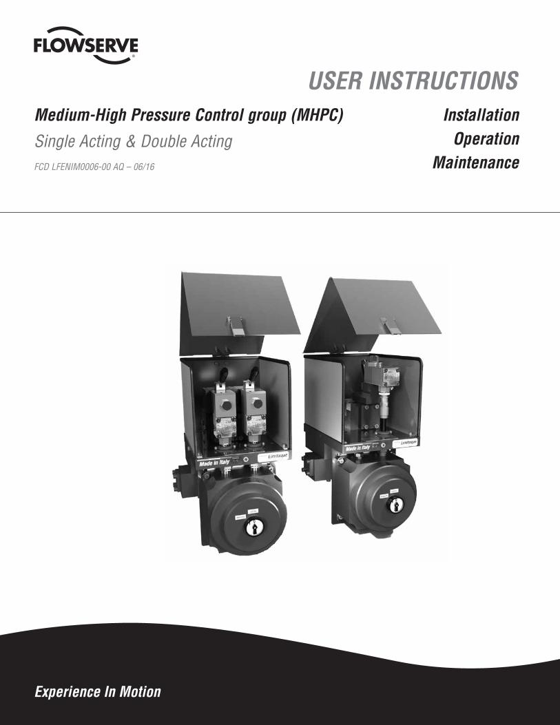
USER INSTRUCTIONSMedium-High Pressure Control group (MHPC)Single Acting & Double Acting FCD LFENIM0006-00 AQ – 06/16
2
MHPC FCD LFENIM0006-00 AQ – 06/16
flowserve.com
CONTENTS
1. Using flowserve valves, actuators and accessories correctly .............................................................4
1.1 Terms concerning safety ....................................................................................................................4
1.2 General usage .....................................................................................................................................4
1.3 Protective clothing ..............................................................................................................................4
1.4 Qualified personnel .............................................................................................................................5
1.5 Other general requirements for in plant installation ..........................................................................5
1.6 Spare parts .........................................................................................................................................5
1.7 Service/repair .....................................................................................................................................5
1.8 Lifting and handling ............................................................................................................................5
1.9 Storage ...............................................................................................................................................8
1.10 Variations ...........................................................................................................................................8
1.11 Unpacking ...........................................................................................................................................8
2 Installation instructions ..........................................................................................................................9
2.1 Medium-High Pressure Control group check.
2.2 Connection with actuator housing and mounting kit .......................................................................10
2.3 Grounding system ............................................................................................................................12
2.4 Initial operation .................................................................................................................................12
3 Accessories ............................................................................................................................................13
3.1 Protection cover ...............................................................................................................................13
4 Maintenance instructions ......................................................................................................................13
5 General disassembly instructions ........................................................................................................14
5.1 General instructions .........................................................................................................................14
5.2 Standard in-field maintenance .........................................................................................................14
5.3 Spare parts .......................................................................................................................................18
6 Troubleshooting .....................................................................................................................................19
7 Disposal of decommissioned control groups .......................................................................................21
8 Annex ......................................................................................................................................................21
3
MHPC FCD LFENIM0006-00 AQ – 06/16
FIGURES
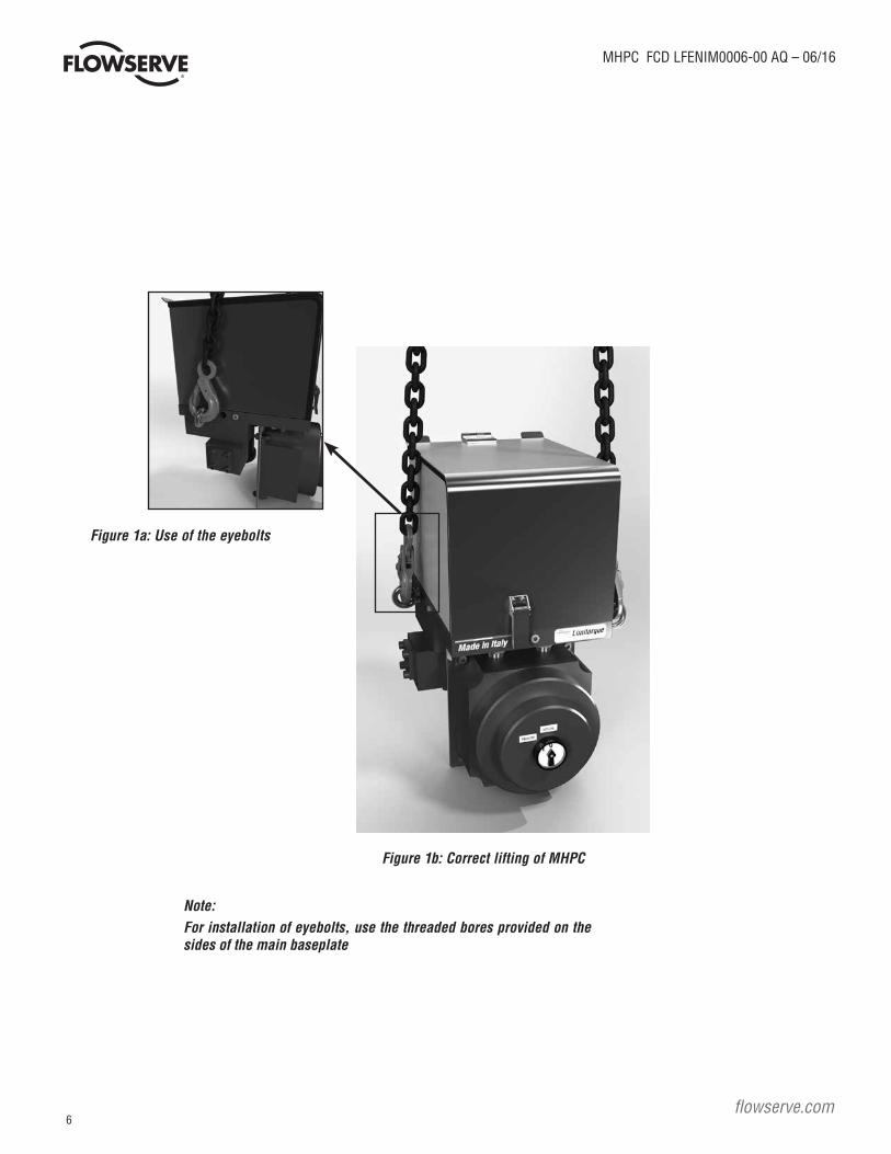
Figure 1a: Use of the eyebolts ...............................................................................................................................6
Figure 1b: Correct lifting of MHPC ........................................................................................................................6
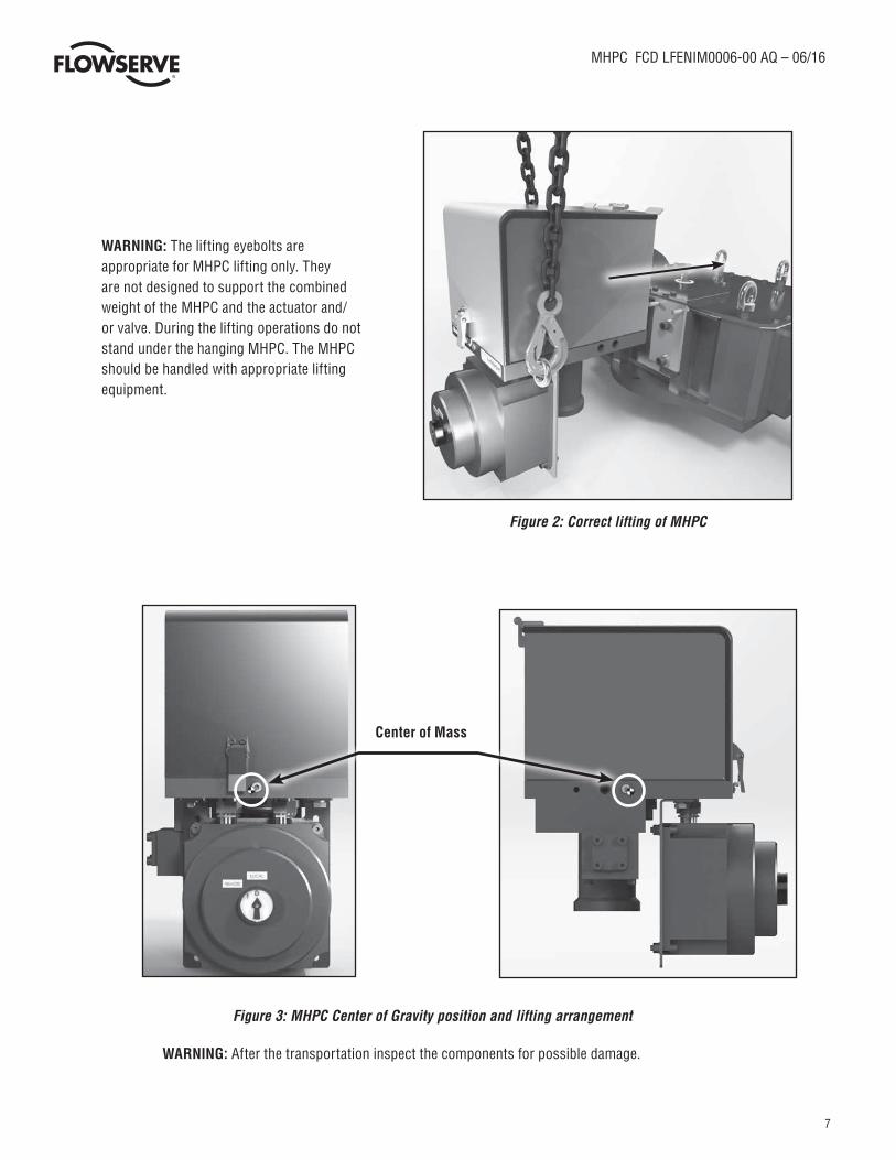
Figure 2: Correct lifting of MHPC ..........................................................................................................................7
Figure 3: MHPC Center of Gravity position and lifting arrangement ....................................................................7
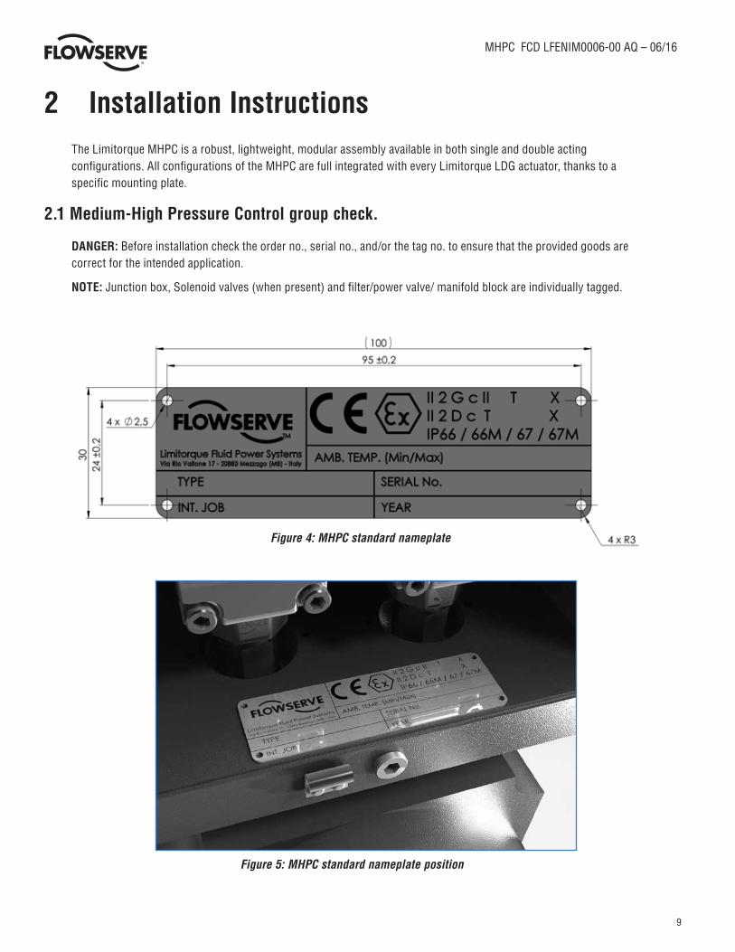
Figure 4: MHPC standard nameplate.....................................................................................................................9
Figure 5: MHPC standard nameplate position ......................................................................................................9
Figure 6: MHPC grounding kit position .............................................................................................................12
Figure 7: Protection Cover example ....................................................................................................................13
Figure 8: MHPC exploded view ...........................................................................................................................22
TABLESTable 1: Spare Parts for standard ON/OFF Applications .....................................................................................18
Table 2: MHPC selection table.............................................................................................................................21
Table 3: Seals Material ........................................................................................................................................21
Table 4: Torque Table for screws without lubricant (tie rods excluded) ............................................................21
Table 5: MHPC parts list ......................................................................................................................................23
4
MHPC FCD LFENIM0006-00 AQ – 06/16
flowserve.com
1 Using Flowserve Valves, Actuators and Accessories Correctly
The following instructions are designed to assist in unpacking, installing and performing maintenance as required on the Medium-High
Pressure Control group (MHPC). Product users and maintenance personnel should thoroughly review this bulletin prior to installing, oper-
ating or performing any maintenance.
In most cases Flowserve actuators and accessories are designed for specific applications with regard to fluid medium, pressure and
temperature. For this reason they should not be used in other applications without first contacting the manufacturer.
1.1 Terms Concerning SafetyThe safety terms DANGER, WARNING, CAUTION and NOTE are used in these instructions to highlight particular dangers and/or to provide
additional information on aspects that may not be readily apparent.
DANGER: indicates that death, severe personal injury and/or substantial property damage will occur if proper precautions are not taken.
WARNING: Refers to personal safety and alerts the user to potential danger. Failure to follow warning notices could result in personal injury
or death.
CAUTION: indicates that minor personal injury and/or property damage can occur if proper precautions are not taken.
NOTE: indicates and provides additional technical information, which may not be very obvious even to qualified personnel.
Compliance with other, not particularly emphasized notes, with regard to transport, assembly, operation and maintenance and with regard
to technical documentation (e.g. in the operating instruction, product documentation or on the product itself) is essential in order to avoid
faults, which in themselves might directly or indirectly cause severe personal injury or property damage.
1.2 General UsageLimitorque High Pressure Control Group (MHPC) is designed to operate with sweet natural gas or other non-corrosive pneumatic fluids
within the indicated pressure range. NACE compliant configurations are available as option (refer to job-specific documentation provided
with goods)
MHPC Standard ambient temperature range is -60°C to 80°C (-76°F to 176°F) polar, cold, arid and tropical temperature requirements in
accordance with IEC 60721. In any case please refer to the temperature range field located in the actuator nameplate.
It is under the end user’s responsibility to guarantee that the ambient temperature is in conformity with the actuator nameplate indications.
WARNING: Minimum and maximum allowable temperatures indicated on the actuator nameplate must be respected. Additional factors such
as direct solar exposure and other environmental conditions must be taken in consideration not to exceed the indicated temperature range.
WARNING: The type and allowable pressure range of the supply fluid stated on the actuator nameplate must be respected. It is very impor-
tant to carry out periodic maintenance of all safety components as defined in the relevant instruction manuals
NOTE: The standard supply fluid is sweet natural gas or other non-corrosive pneumatic fluid. Different type of fluids can be acceptable after
verification by factory. In case of PED requirement, the fluid medium is indicated on a nameplate on the actuator cylinder. Limitorque’s MHPC
is includes a coalescing and a mechanical filter suitable to guarantee the correct operation of the system and the served Limitorque actuator.
1.3 Protective ClothingFlowserve products are often used in critical applications (e.g. extremely high pressures, dangerous, toxic or corrosive media). When
performing service, inspection or repair operations, always ensure that the valves, actuator and MHCP are depressurized and are clean and
free from harmful substances. In such cases pay particular attention to personal protection (protective clothing, gloves, glasses etc.).

5
MHPC FCD LFENIM0006-00 AQ – 06/16
1.4 Qualified PersonnelQualified personnel are people who, on account of their training, experience and instruction and their knowledge of relevant standards,
specifications, accident prevention regulations and operating conditions, have been authorized by those responsible for the safety of the
plant to perform the necessary work and who can recognize and avoid possible dangers.
1.5 Other General Requirements for in-plant Installation• Pipelines must be correctly aligned to ensure that the valve is not fitted under tension.
• If not expressly agreed, fire protection is not supplied along with the MHPC and it must be provided by user.
1.6 Spare PartsUse only Flowserve original spare parts. Flowserve cannot accept responsibility for any damages that occur from using spare parts or
fastening materials from other manufacturers. If Flowserve products (especially sealing materials) have been on store for long periods
check these for corrosion or deterioration before using these products. A table with the list of the main spare parts for standard applica-
tions with the interval times can be found in 5.3 Table 1.
1.7 Service/RepairOnly Allen wrenches and hexagonal wrenches of a few sizes are required for the overall operations.
To avoid possible injury to personnel or damage to products, safety terms must be strictly adhered to. Modifying this product, substituting
non-factory parts, or using maintenance procedures other than as outlined in this instruction could drastically affect performance and be
hazardous to personnel and equipment, and may void existing warranties.
In addition to the operating instructions and the obligatory accident prevention directives valid in the country of use, all recognized regula-
tions for safety and good engineering practices must be followed.
WARNING: Before products are returned to Flowserve for repair or service, Flowserve must be provided with a certificate which confirms
that the product has been decontaminated and is clean. Flowserve will not accept deliveries if a certificate has not been provided (a form
can be obtained from Flowserve).
1.8 Lifting and HandlingThe MHPC is typically supplied installed on board of the relevant Limitorque gas-powered actuator. In case it becomes necessary to lift
the MHPC separately from the actuator, it is provided with 2 threaded holes suitable for ISO 3266 M10 eyebolts (not included in supply).
Screw the eyebolts into the threaded holes and lift with appropriate lifting tackle.
In order to prevent damage to actuator accessories, before starting the lifting operations, ensure that the lifting tools, like chain and clevis
hook, are in correct position and don’t interfere with the equipment.
CAUTION: Lifting and handling of the MHPC should be done by qualified staff and in compliance with the laws and regulations in force.
WARNING: Do not use eyebolts or other equipment different from ISO 3266 M10 eyebolts to lift the MHPC.
WARNING: The mentioned ISO 3266 M10 eyebolts are appropriate for MHPC lifting only. They are not designed to support the combined
weight of the MHPC and the actuator and/or valve. During the lifting operations do not stand under the hanging MHPC. The MHPC should
be handled with appropriate lifting equipment. Where the MHPC is supplied assembled onto a Limitorque actuator, use the actuator lifting
points to lift the complete assembly. The total weight of the assembly to be lifted is reported on the packing slip and is indicated the on the
overall dimensions drawing furnished in the goods documentation package.
6
MHPC FCD LFENIM0006-00 AQ – 06/16
flowserve.com
Note: For installation of eyebolts, use the threaded bores provided on the sides of the main baseplate
Figure 1b: Correct lifting of MHPC
Figure 1a: Use of the eyebolts
7
MHPC FCD LFENIM0006-00 AQ – 06/16
Center of Mass
Figure 3: MHPC Center of Gravity position and lifting arrangement
WARNING: After the transportation inspect the components for possible damage.
WARNING: The lifting eyebolts are appropriate for MHPC lifting only. They are not designed to support the combined weight of the MHPC and the actuator and/or valve. During the lifting operations do not stand under the hanging MHPC. The MHPC should be handled with appropriate lifting equipment.
Figure 2: Correct lifting of MHPC
8
MHPC FCD LFENIM0006-00 AQ – 06/16
flowserve.com
1.9 StorageFlowserve products are typically provided with an epoxy resin coating or with other painting systems as agreed with the customer. This means that Flowserve products are well protected from corrosion. Nevertheless, in order to maintain good working conditions and a good finish until the actuator is installed on the plant, it is necessary to follow a few rules during the storage period:
• Flowserve products must be stored adequately in a clean, dry environment. • Ensure that plastic caps are fitted to protect the pneumatic connections and the cable entries, to prevent the
ingress of foreign materials. These caps should not be removed until the product is actually mounted into the system.
• The product must be placed on a wooden pallet or other suitable support, to avoid contact between the product surfaces and the ground.
• If the storage is outdoors, or if long-term storage (more than four months) is necessary, the plastic protection plugs have to be replaced by metal ones.
• In case of long-term storage (more than four months), provide a tarpaulin cover or some other means of protection, especially if the storage is outdoor.
1.10 VariationsThese instructions cannot claim to cover all details of all possible product variations, nor can they provide information for every possible example of installation, operation or maintenance. This means that the instructions normally include only the directions to be followed by qualified personnel where the product is being used for its defined purpose. If there are any uncertainties in this respect particularly in the event of missing product-related information, clarification must be obtained via the appropriate Flowserve sales office.
1.11 Unpacking• Each delivery includes a packing slip. When unpacking, check all delivered goods using this packing slip.• Report transport damage to the carrier immediately.• In case of discrepancies, contact your nearest Flowserve location.• If necessary, retouch minor damage to the paint coating which may have occurred during transport or
storage.
NOTE: When the MHPC has ATEX requirements, ensure that the “MHPC Safety Extract and Instruction Manual” (Explosive Atmosphere Equipment and ATEX Certification) accompany this manual and is referred to for equipment storage.
NOTE: When the MHPC has SIL requirements, ensure that the ““High Pressure Control Group (MHPC) Series Safety Manual” (Functional Safety and SIL Certification) accompany this manual and is referred to for equipment usage.
9
MHPC FCD LFENIM0006-00 AQ – 06/16
2 Installation InstructionsThe Limitorque MHPC is a robust, lightweight, modular assembly available in both single and double acting configurations. All configurations of the MHPC are full integrated with every Limitorque LDG actuator, thanks to a specific mounting plate.
2.1 Medium-High Pressure Control group check.
DANGER: Before installation check the order no., serial no., and/or the tag no. to ensure that the provided goods are correct for the intended application.
NOTE: Junction box, Solenoid valves (when present) and filter/power valve/ manifold block are individually tagged.
Figure 5: MHPC standard nameplate position
Figure 4: MHPC standard nameplate

10
MHPC FCD LFENIM0006-00 AQ – 06/16
flowserve.com
2.2 Connection with Actuator Housing and Mounting Kit The MHPC is typically supplied already installed on board of the relevant Limitorque gas-powered actuator. The MHPC is
assembled onto the actuator using a dedicated plate which connects the rear part of the base plate to the actuator center body.
In case it is necessary to assemble or remove the MHPC from the actuator, follow the instructions below:
Check the mounting surfaces of the MHPC, mounting plate and actuator mounting brackets and check also the position of the holes to assure the proper fit. Clean the mounting surface of all parts to be assembled to remove oils and greases. Also remove any rust that may have occurred during storage.
Tighten the two socket-screws properly (using Loctite) to ensure a correct coupling between mounting plate and the MHPC.
11
MHPC FCD LFENIM0006-00 AQ – 06/16
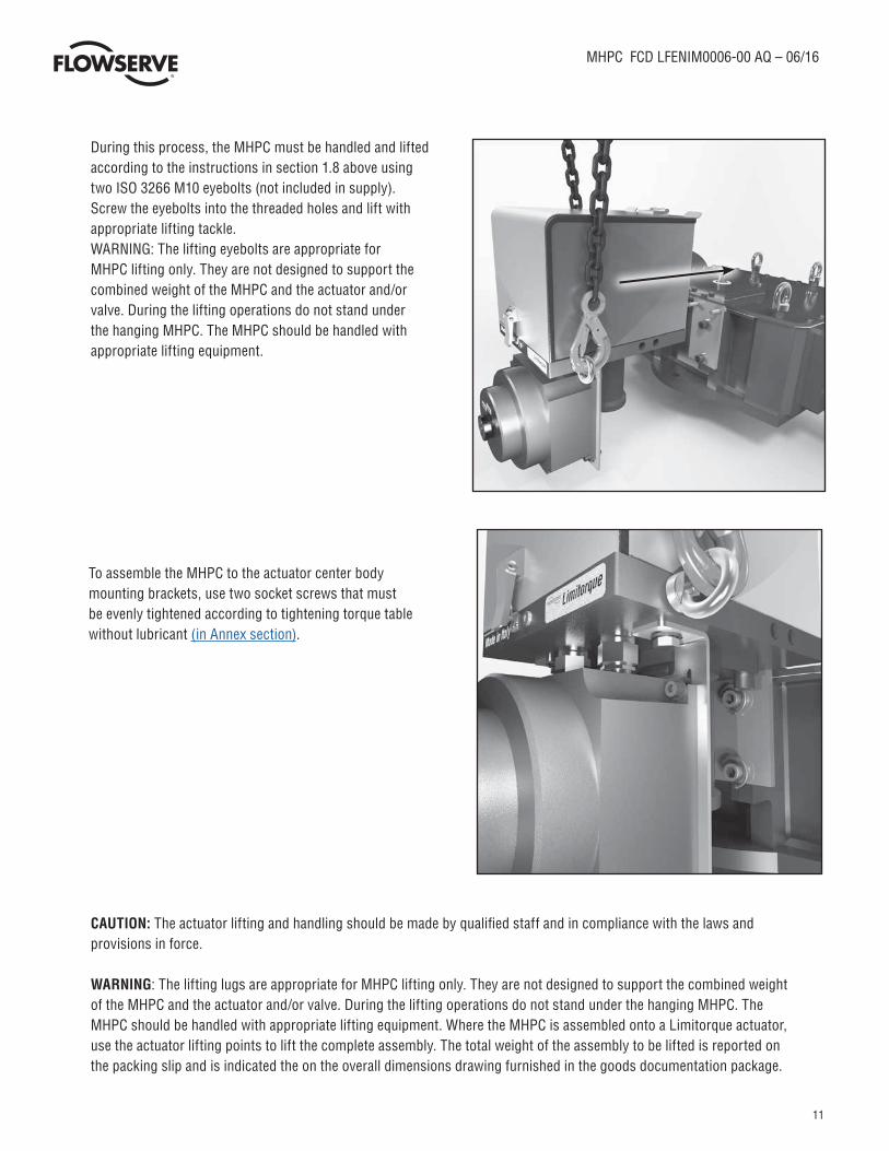
During this process, the MHPC must be handled and lifted according to the instructions in section 1.8 above using two ISO 3266 M10 eyebolts (not included in supply). Screw the eyebolts into the threaded holes and lift with appropriate lifting tackle.WARNING: The lifting eyebolts are appropriate for MHPC lifting only. They are not designed to support the combined weight of the MHPC and the actuator and/or valve. During the lifting operations do not stand under the hanging MHPC. The MHPC should be handled with appropriate lifting equipment.
To assemble the MHPC to the actuator center body mounting brackets, use two socket screws that must be evenly tightened according to tightening torque table without lubricant (in Annex section).
CAUTION: The actuator lifting and handling should be made by qualified staff and in compliance with the laws and provisions in force.
WARNING: The lifting lugs are appropriate for MHPC lifting only. They are not designed to support the combined weight of the MHPC and the actuator and/or valve. During the lifting operations do not stand under the hanging MHPC. The MHPC should be handled with appropriate lifting equipment. Where the MHPC is assembled onto a Limitorque actuator, use the actuator lifting points to lift the complete assembly. The total weight of the assembly to be lifted is reported on the packing slip and is indicated the on the overall dimensions drawing furnished in the goods documentation package.
12
MHPC FCD LFENIM0006-00 AQ – 06/16
flowserve.com
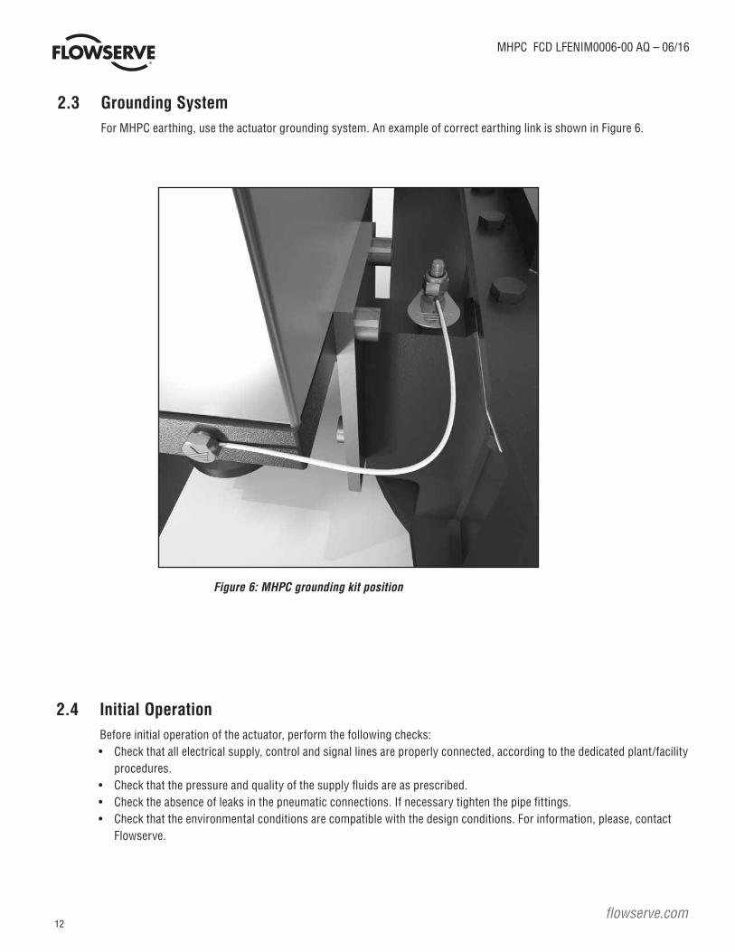
2.3 Grounding System For MHPC earthing, use the actuator grounding system. An example of correct earthing link is shown in Figure 6.
2.4 Initial Operation Before initial operation of the actuator, perform the following checks:
• Check that all electrical supply, control and signal lines are properly connected, according to the dedicated plant/facility procedures.
• Check that the pressure and quality of the supply fluids are as prescribed.• Check the absence of leaks in the pneumatic connections. If necessary tighten the pipe fittings.• Check that the environmental conditions are compatible with the design conditions. For information, please, contact
Flowserve.
Figure 6: MHPC grounding kit position
13
MHPC FCD LFENIM0006-00 AQ – 06/16
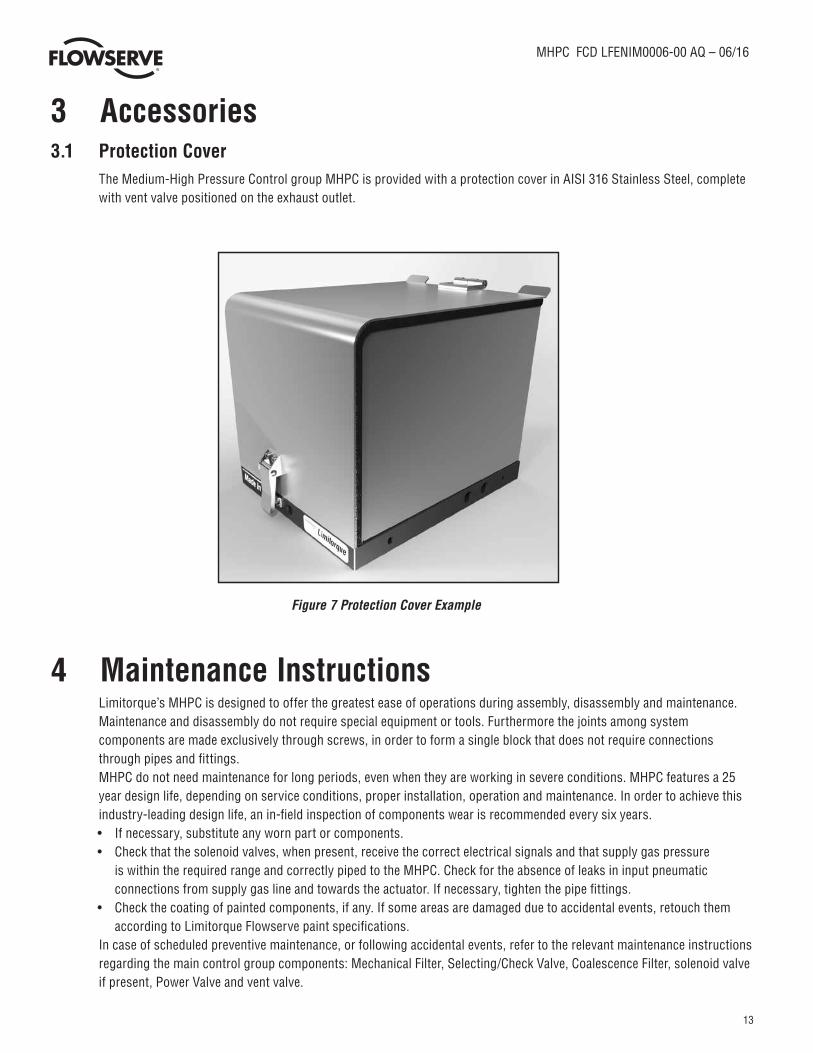
3 Accessories3.1 Protection Cover The Medium-High Pressure Control group MHPC is provided with a protection cover in AISI 316 Stainless Steel, complete
with vent valve positioned on the exhaust outlet.
Figure 7 Protection Cover Example
4 Maintenance Instructions Limitorque’s MHPC is designed to offer the greatest ease of operations during assembly, disassembly and maintenance.
Maintenance and disassembly do not require special equipment or tools. Furthermore the joints among system components are made exclusively through screws, in order to form a single block that does not require connections through pipes and fittings.
MHPC do not need maintenance for long periods, even when they are working in severe conditions. MHPC features a 25 year design life, depending on service conditions, proper installation, operation and maintenance. In order to achieve this industry-leading design life, an in-field inspection of components wear is recommended every six years. • If necessary, substitute any worn part or components. • Check that the solenoid valves, when present, receive the correct electrical signals and that supply gas pressure
is within the required range and correctly piped to the MHPC. Check for the absence of leaks in input pneumatic connections from supply gas line and towards the actuator. If necessary, tighten the pipe fittings.
• Check the coating of painted components, if any. If some areas are damaged due to accidental events, retouch them according to Limitorque Flowserve paint specifications.
In case of scheduled preventive maintenance, or following accidental events, refer to the relevant maintenance instructions regarding the main control group components: Mechanical Filter, Selecting/Check Valve, Coalescence Filter, solenoid valve if present, Power Valve and vent valve.
14
MHPC FCD LFENIM0006-00 AQ – 06/16
flowserve.com
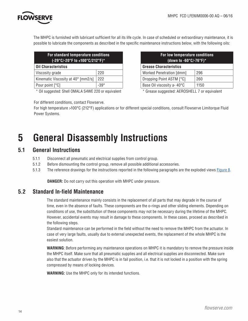
The MHPC is furnished with lubricant sufficient for all its life cycle. In case of scheduled or extraordinary maintenance, it is possible to lubricate the components as described in the specific maintenance instructions below, with the following oils:
For standard temperature conditions(-29°C/-20°F to +100°C/212°F)*
Oil CharacteristicsViscosity grade 220Kinematic Viscosity at 40° [mm2/s] 222Pour point [°C] -39°* Oil suggested: Shell OMALA S4WE 220 or equivalent
For low temperature conditions(down to -60°C/-76°F)*
Grease CharacteristicsWorked Penetration [dmm] 296Dropping Point ASTM [°C] 260Base Oil viscosity a- 40°C 1150* Grease suggested: AEROSHELL 7 or equivalent
For different conditions, contact Flowserve.For high temperature >100°C (212°F) applications or for different special conditions, consult Flowserve Limitorque Fluid Power Systems.
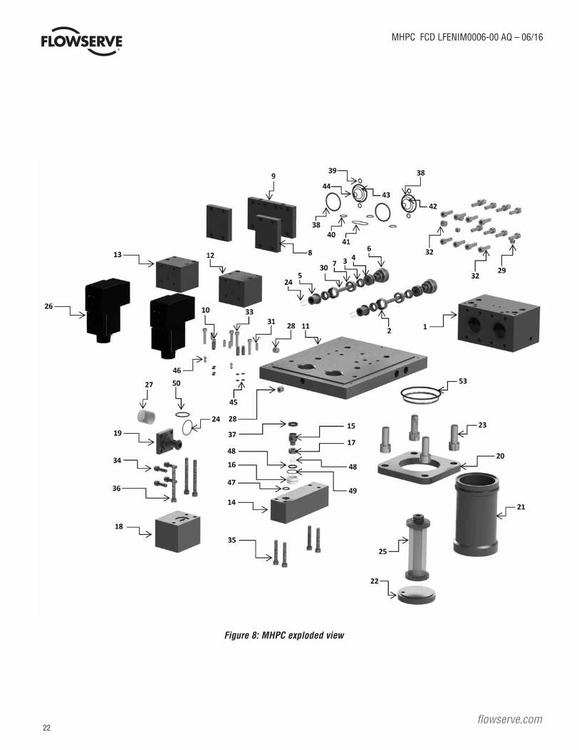
5 General Disassembly Instructions5.1 General Instructions 5.1.1 Disconnect all pneumatic and electrical supplies from control group. 5.1.2 Before dismounting the control group, remove all possible additional accessories. 5.1.3 The reference drawings for the instructions reported in the following paragraphs are the exploded views Figure 8.
DANGER: Do not carry out this operation with MHPC under pressure.
5.2 Standard In-field Maintenance The standard maintenance mainly consists in the replacement of all parts that may degrade in the course of
time, even in the absence of faults. These components are the o-rings and other sliding elements. Depending on conditions of use, the substitution of these components may not be necessary during the lifetime of the MHPC. However, accidental events may result in damage to these components. In these cases, proceed as described in the following steps.
Standard maintenance can be performed in the field without the need to remove the MHPC from the actuator. In case of very large faults, usually due to external unexpected events, the replacement of the whole MHPC is the easiest solution.
WARNING: Before performing any maintenance operations on MHPC it is mandatory to remove the pressure inside the MHPC itself. Make sure that all pneumatic supplies and all electrical supplies are disconnected. Make sure also that the actuator driven by the MHPC is in fail position, i.e. that it is not locked in a position with the spring compressed by means of locking devices.
WARNING: Use the MHPC only for its intended functions.
15
MHPC FCD LFENIM0006-00 AQ – 06/16
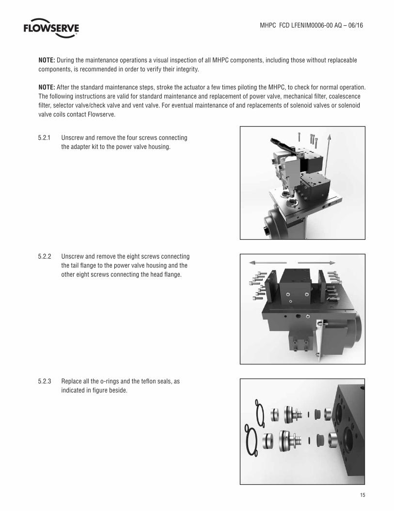
NOTE: During the maintenance operations a visual inspection of all MHPC components, including those without replaceable components, is recommended in order to verify their integrity.
NOTE: After the standard maintenance steps, stroke the actuator a few times piloting the MHPC, to check for normal operation. The following instructions are valid for standard maintenance and replacement of power valve, mechanical filter, coalescence filter, selector valve/check valve and vent valve. For eventual maintenance of and replacements of solenoid valves or solenoid valve coils contact Flowserve.
5.2.1 Unscrew and remove the four screws connecting the adapter kit to the power valve housing.
5.2.2 Unscrew and remove the eight screws connecting the tail flange to the power valve housing and the other eight screws connecting the head flange.
5.2.3 Replace all the o-rings and the teflon seals, as indicated in figure beside.

16
MHPC FCD LFENIM0006-00 AQ – 06/16
flowserve.com
5.2.4 Replace also the o-rings indicated in figure. The Teflon seal support indicated in the rectangle is chamfered, so replace the whole block made of teflon seal and chamfered Teflon seal support.
5.2.5 Remove all the o-rings and replace them with new ones. Clean all the surface of piston and flanges in contact with these components with a clean rag and solvent compatible with O-ring material (for information contact Flowserve). Brush the o-rings grooves with a light oil film and install the new o-rings. Spread a thin layer of oil on the bottom of the guide ring grooves and install new guide rings. Clean the internal surfaces of power valve housing and lubricate with a protective oil film.
5.2.6 To change the Coalescence Filter Cartridge, unscrew the tube and the tail flange together, using the two pins provided on the bottom of the filter tail flange and applying a suitable lever element such as a wrench.
5.2.7 Extract and replace the Coalescence Filter Cartridge and all the O-rings.

17
MHPC FCD LFENIM0006-00 AQ – 06/16
5.2.8 Remove the Mechanical Filter unscrewing the four screws. Remove the mechanical filtering element support removing the four screws, replace the filtering element and the O-rings.
5.2.9 When the Mechanical Filter is removed, replace the Selector/Check Valve Spare parts, as shown.
5.2.10 Remove the Vent Valve by unscrewing the hex nut shown in the figure.
When the vent valve is removed, replace the relevant spare parts, as shown.
NOTE: After the standard maintenance steps, pilot the MHPC a few times to check for normal operation.

18
MHPC FCD LFENIM0006-00 AQ – 06/16
flowserve.com
5.3 Spare Parts The main spare parts and the interval time for standard ON/OFF applications are listed in the table below. Maintenance for
standard ON/OFF applications is recommended after 1800 cycles and/or after six years of usage, whichever occurs first. To obtain spare parts lists specific for each job/order, please contact your Flowserve Limitorque representative. Part numbers are referred to Figure 8.
Table 1: Spare Parts for standard ON/OFF Applications
WARNING: The regular maintenance interval times suggested in table 1 above must be followed.
* Spare parts that can be replaced without removing the actuator from the valve.
Number Description Mainenance Interval TimesMHPC removal from the
actuator2 Power Valve Seal Spport 6 Years 1800 Cycles Not required (*)3 Power Valve Seal 6 Years 1800 Cycles Not required (*)7 Power Valve Chamfered Seal Support 6 Years 1800 Cycles Not required (*)
25 Coalescer Filter 6 Years 1800 Cycles Not required (*)37 Tape Guide 6 Years 1800 Cycles Not required (*)38 O-Ring 6 Years 1800 Cycles Not required (*)39 O-Ring 6 Years 1800 Cycles Not required (*)40 O-Ring 6 Years 1800 Cycles Not required (*)41 O-Ring 6 Years 1800 Cycles Not required (*)42 O-Ring 6 Years 1800 Cycles Not required (*)43 O-Ring 6 Years 1800 Cycles Not required (*)44 O-Ring 6 Years 1800 Cycles Not required (*)45 O-Ring 6 Years 1800 Cycles Not required (*)46 O-Ring 6 Years 1800 Cycles Not required (*)47 O-Ring 6 Years 1800 Cycles Not required (*)49 O-Ring 6 Years 1800 Cycles Not required (*)50 O-Ring 6 Years 1800 Cycles Not required (*)51 O-Ring 6 Years 1800 Cycles Not required (*)52 O-Ring 6 Years 1800 Cycles Not required (*)53 O-Ring 6 Years 1800 Cycles Not required (*)
19
MHPC FCD LFENIM0006-00 AQ – 06/16
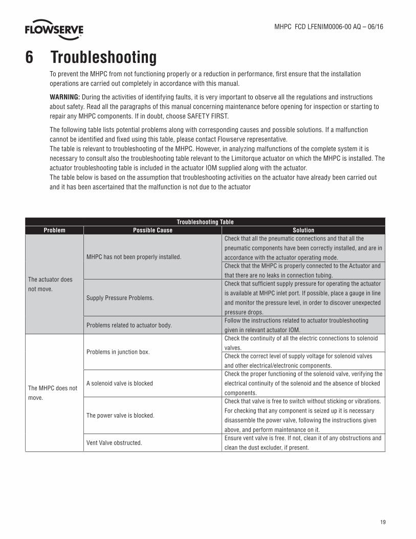
6 Troubleshooting To prevent the MHPC from not functioning properly or a reduction in performance, first ensure that the installation
operations are carried out completely in accordance with this manual.
WARNING: During the activities of identifying faults, it is very important to observe all the regulations and instructions about safety. Read all the paragraphs of this manual concerning maintenance before opening for inspection or starting to repair any MHPC components. If in doubt, choose SAFETY FIRST.
The following table lists potential problems along with corresponding causes and possible solutions. If a malfunction cannot be identified and fixed using this table, please contact Flowserve representative.
The table is relevant to troubleshooting of the MHPC. However, in analyzing malfunctions of the complete system it is necessary to consult also the troubleshooting table relevant to the Limitorque actuator on which the MHPC is installed. The actuator troubleshooting table is included in the actuator IOM supplied along with the actuator.
The table below is based on the assumption that troubleshooting activities on the actuator have already been carried out and it has been ascertained that the malfunction is not due to the actuator
Troubleshooting TableProblem Possible Cause Solution
The actuator does
not move.
MHPC has not been properly installed.
Check that all the pneumatic connections and that all the
pneumatic components have been correctly installed, and are in
accordance with the actuator operating mode.Check that the MHPC is properly connected to the Actuator and
that there are no leaks in connection tubing.
Supply Pressure Problems.
Check that sufficient supply pressure for operating the actuator
is available at MHPC inlet port. If possible, place a gauge in line
and monitor the pressure level, in order to discover unexpected
pressure drops.
Problems related to actuator body.Follow the instructions related to actuator troubleshooting
given in relevant actuator IOM.
The MHPC does not
move.
Problems in junction box.
Check the continuity of all the electric connections to solenoid
valves.Check the correct level of supply voltage for solenoid valves
and other electrical/electronic components.
A solenoid valve is blocked
Check the proper functioning of the solenoid valve, verifying the
electrical continuity of the solenoid and the absence of blocked
components.
The power valve is blocked.
Check that valve is free to switch without sticking or vibrations.
For checking that any component is seized up it is necessary
disassemble the power valve, following the instructions given
above, and perform maintenance on it.
Vent Valve obstructed.Ensure vent valve is free. If not, clean it of any obstructions and
clean the dust excluder, if present.

20
MHPC FCD LFENIM0006-00 AQ – 06/16
flowserve.com
Troubleshooting TableProblem Possible Cause Solution
The MHPC does not
move.
Problem with lubricants.
Ensure that the MHPC is properly lubricated, and that there is
no solidified grease among sliding parts. If MHPC lubrication
is inadequate or improper, apply a uniform lubricant layer,
following the relevant instructions for maintenance. See section
4 for proper oil and grease to be used.
Leakages from MHPC components joint through
screws.
A significant pneumatic leak may prevent the MHPC from
operating. Ensure that there are no leaks in the MHPC main
components, due to damage of o-rings. If possible, detect them
using a leak finder spray.
Using the same spray, check that there are no leaks in tubing
and fittings from the supply line and towards the actuator.
The MHPC model is not the correct one.
For double acting MHPCs, check the information on nameplate,
verifying that the solenoid valve configuration (NC/NC) or
(NC/NA) is in accordance with plant requirements. If there are
mismatches, contact Flowserve Service Department.
The MHPC is not suitable for the plant conditions.Check the MHPC nameplate and the plant requirements. If there
are mismatches, contact Flowserve Service Department.
Spring Problems, preventing proper operation of the
MHPC.
Check the status of the spring of: selector/check valve, power
valve and vent valve, performing the maintenance instructions
described above. If recurrent problems are found, contact
Flowserve Service Department.Perform the following test: measure the minimum pressure
value necessary to operate the MHPC, compressing all the
springs of its components. Compare the measured values
with the one reported on the Testing Certificate. If there are
significant differences you should contact Flowserve Service
Department.A lockout device has been inserted and forgotten in
that position.
If the MHPC is provided with special lockout devices, ensure
they are disconnected.During the stroke the
power valve exhibits
excessive amounts
of backlash.
Some components are excessively worn.
Identify and replace these components, according to the
maintenance instructions described in the relevant paragraphs
of this manual.
The actuator does
not fully perform
the stroke, during
opening and closing.
Vent valve obstructed Ensure vent valve is free. If not, clean it of any obstruction and
clean the dust excluder, if present.
Actuator torque lower than required
Check the supply pressure value is within the required range.
For verifying the minimum pressure to operate the actuator,
refer to actuator IOM. If there are significant differences you
should contact Flowserve Service Department.
The actuator is not correctly adjusted.Follow the instructions related to actuator troubleshooting
given in relevant actuator IOM.The valve does not
shut off properly and
there are leaks.
The actuator is not correctly adjusted.Follow the instructions related to actuator troubleshooting
given in relevant actuator IOM.
In case of other problems not listed in this table, please contact the Flowserve Service Department.

21
MHPC FCD LFENIM0006-00 AQ – 06/16
7 Disposal of Decommissioned Control groups If MHPC units are to be decommissioned permanently due to a plant closure or for any other reason, they can be
disassembled according to the general instructions give in section 5. Different component materials can then be disposed of and/or recycled in the most appropriate way.
8 Annex
Table 2: Model Selection Table
Code Material Temperature Range Climate Classification according to IEC60721B Buna Std Temp: -29°C to +100°C (-20°F to 212°F)
Tropical & AridV Viton® High Temp: up to +160°C (320°F)S Silicon Low Temp: down to -40°C (-40°F) TemperateZ Other Special Applications – Consult Factory Cold & Polar
Table 3: Seals Material
Table 4: Torque Table for screws without lubricant (tie rods excluded) – applicable also to mounting kit
Screw Diameter Torque [Nm]
M3 0,5M4 1,3M5 2,5M6 4,3M8 11M10 21M12 36M14 48M18 89M20 124
MHPC -
Local/Remote + Line Break
-1 D1 - LT
Mai
n fu
nctio
nalit
y
...
1
2B -
Local/Remote + dedicated ESD
4
5
2
3
Inle
t con
nect
ions
Seal
Mat
eria
l B - BUNA
V - VITON®
S - SILICON
Z - SPECIAL
1
2
SOV
/ PI
LOT
conf
igur
atio
nLocal Operation
Local/Remote Operation
Local/Remote + High/Low pressure shutdown
example model n°
S1 - NC
D1 - NC/NC
D2 - NC/NO
Avai
labl
e O
ptio
ns
LT - LOW TEMPERATURE
NV - NACE VERSION
SS - STAINLESS STEEL BUILD
22
MHPC FCD LFENIM0006-00 AQ – 06/16
flowserve.com
Figure 8: MHPC exploded view

23
MHPC FCD LFENIM0006-00 AQ – 06/16
Table 5: MHPC parts list
Item description material quantity spare parts
1 Power valve housing Alluminium 1
2 Power valve seal spport Stainless Steel 2 x
3 Power valve seal Teflon 4 x
4 Power valve piston Stainless Steel 2
5 Spring support Stainless Steel 2
6 Power valve piston support Stainless Steel 2
7 Power valve chamfered seal support Stainless Steel 2 x
8 Power valve head flange Alluminium 2
9 Power valve tail flange Alluminium 1
10 Junction cylinder Stainless Steel 4
11 Base plate Alluminium 1
12 Adapter base - right Alluminium 1
13 Adapter base - left Alluminium 1
14 Selecting/check valve housing Alluminium 1
15 Selecting valve spring support Stainless Steel 1
16 Selecting valve guide Stainless Steel 1
17 Selecting valve seal support Rubber 1
18 Mechanical filter housing Alluminium 1
19 Mechanical filter support Alluminium 1
20 Head flange Alluminium 1
21 Coalescer filter tube Carbon Steel 1
22 Coalescer filter tail flange Carbon Steel 1
23 Socket screw Alloy Steel 4
24 Compression spring Spring Stainless Steel 2
25 Coalescer filter Stainless Steel + Borosilicate + Cellulose 1 x
26 Solenoid valve 3/2 Commercial Component 2
27 Mechanical filter Stainless Steel 1
28 Inner exagon plug Stainless Steel 4
29 Inner exagon plug Stainless Steel 4
30 Parallel pin Alloy Steel 2
31 Grub screw Alloy Steel 4
32 Socket screw Alloy Steel 16
33 Socket screw Alloy Steel 4
34 Socket screw Alloy Steel 4
35 Socket screw Alloy Steel 4
36 Socket screw Alloy Steel 3
37 Tape guide Ptfe+Graphite 1 x
38 O-ring Rubber 4 x
39 O-ring Rubber 4 x
40 O-ring Rubber 3 x
41 O-ring Rubber 1 x
42 O-ring Rubber 2 x
43 O-ring Rubber 2 x
44 O-ring Rubber 2 x
45 O-ring Rubber 8 x
46 O-ring Rubber 4 x
47 O-ring Rubber 1 x
48 Compression spring Spring Stainless Steel 1
49 O-ring Rubber 1 x
50 O-ring Rubber 1 x
51 O-ring Rubber 1 x
52 O-ring Rubber 1 x
53 O-ring Rubber 1 x
X spare parts that can be replaced.
24
MHPC FCD LFENIM0006-00 AQ – 06/16
flowserve.com
Flowserve Corporation has established industry leadership in the design and manufacture of its products. When properly selected, this Flowserve product is designed to perform its inten-ded function safely during its useful life. However, the purchaser or user of Flowserve products should be aware that Flowserve products might be used in numerous applications under a wide variety of industrial service conditions. Although Flowserve can (and often does) provide general guidelines, it cannot provide specific data and warnings for all possible applications. The purchaser/user must therefore assume the ultimate responsibility for the proper sizing and selection, installation, operation, and maintenance of Flowserve products. The purchaser/user should read and understand the Installation Operation Maintenance (IOM) instructions included with the product, and train its employees and contractors in the safe use of Flowserve products in connection with the specific application.While the information and specifications contained in this literature are believed to be accurate, they are supplied for informative purposes only and should not be considered certified or as a guarantee of satisfactory results by reliance thereon. Nothing contained herein is to be construed as a warranty or guarantee, express or implied, regarding any matter with respect to this product. Because Flowserve is continually improving and upgrading its product design, the specifications, dimensions and information contained herein are subject to change without notice. Should any question arise concerning these provisions, the purchaser/user should contact Flowserve Corporation at any one of its worldwide operations or offices.© 2016 Flowserve Corporation, Irving, Texas, USA. Flowserve is a registered trademark of Flowserve Corporation.
FCD LFENIM0006-00 AQ - 06/16 Printed in USA.
To find your local Flowserve representative, visit:www.flowserve.com or call: USA + 1 800 225 6989 International +1 972 910 0774
Flowserve Limitorque Fluid-Power Product Sales via Rio Vallone 17 20883 Mezzago MB Italy Fax: +39 039 62060 213Phone: +39 620 601 200Email: [email protected]
Flowserve Limitorque Fluid-Power ProductManufacturing and Operationsvia Rio Vallone 17 20883 Mezzago MB Italy Fax: +39 039 62060 213Phone: +39 620 601 200Email: [email protected]
Flowserve Limitorque Fluid-Power ProductResearch and DevelopmentVia Belizzi 40/42 29122 Piacenza, PC Italy Email: [email protected]