mecp basic study guide
DESCRIPTION
Car Audio installationTRANSCRIPT
Basic Installer Study Guide

The Basic Installer Study Guide is based on carefully docu-mented material and research. Every attempt has been madeto relay accurate and up-to-date information. This book isdesigned to assist Mobile Electronics Installers in passing theMECP Basic Installer Test and can also be used as a referenceguide. MECP and/or the Consumer Electronics Associationcannot be held responsible for discrepancies or inconsisten-cies contained in this publication.
Copyright © 2000 by Consumer Electronics Association/First Edition
All rights reserved. No part of this work covered by thecopyright hereon may be reproduced or used in any form orby any means - graphic, electronics, or mechanical, includ-ing photocopying, recording, taping or information storageand retrieval systems - without the written permission of thepublisher.
MECPConsumer Electronics Association2500 Wilson BoulevardArlington, Virginia 22201-3834(703) 907-7689

CONTRIBUTORS
CONTRIBUTORS THE BASIC INSTALLER STUDY GUIDE 3
WRITERS AND CONTRIBUTING EDITORSEric AbbissWayde AlfaronePaul BairdJohn BanseWard BenjaminBob BentleyJim BoyteKris BullaDennis DeckTim Den HartogCharlie FoxMark FukudaJoe GarrubaTom GazdaDoug GiddensMary Ann GiorgioLonnie GoddardMark GordonJeff HalkinHomer HawlinsScott HeidbrinkStan HoffmanJim Jardin
CONTRIBUTING COMPANIESAlpine ElectronicsATX ResearchAudio Comp Electronics, Inc.Audio ControlAudivoxBenjamin ConsultingBobit PublishingCar Audio EngineeringCMA School of Mobile ElectronicsDirected Electronics, Inc.Installer InstituteJBL Car AudioListen UpLuzerne County Community College,Advanced Technology Center
MANAGING EDITOR
Chris Cook ..............................................MECP
DESIGN AND PRODUCTION
Alpha MicroDesigns, Inc. ........................http://www.amdi.com
Dan JobinEd KuehnerDerek LeeDavid LongMartin MarinoJames MiltonTed PetersonJoe PetreauTodd RamseyRudy SandersAllen SchultzKerry ShrodeGeoff SmithKenny SnoddyDave SprostyJustin StanleyJerry SterlingGil StroudTodd VanZandtJoe WaltersPaul WandersKen Ward
Mobile DynamicsMobile One Auto SoundMobilworksOra ElectronicsPioneer ElectronicsQuality Auto SoundRobert Bentley AudioSherwoodSouth Bay Cellular Telephone CompanyStillwater DesignsVehicle Security ElectronicsTraffic Jams
MECP would like tothank the following manufacturers:
Alpine, Code Alarm,Directed Electronics,Kenwood, MetraElectronics Corporation,Pioneer Electronics,Scosche Industries, and Vehicle SecurityElectronics for their continued support of the program and contributions to this book.
TABLE OF CONTENTS
THE BASIC INSTALLER STUDY GUIDE TABLE OF CONTENTS4
INTRODUCTION
Understanding The Format ............................................................10What Is MECP…And What Does It Mean To You? ........................11Why Certification Is Essential: Customer Perceptions ....................11Botton Line Benefits........................................................................11Making The Most Of This Study Guide ..........................................12Understanding The MECP Tests ....................................................13How The Tests Are Created ............................................................19Preparing For The Exam ................................................................20The Day Before The Test ................................................................20The Day Of The Test ......................................................................21At The Test Site ..............................................................................21How To Take The Test ....................................................................22After The Test ................................................................................23
CHAPTER 1 - BASIC AND ADVANCED ELECTRICAL
Section 1 - Electrical Laws And Formulas For The Mobile Electronics Environment ..................................................................26
Understanding OHM’s Law ............................................................28Electrical Power ..............................................................................34Series And Parallel Total Resistance Formulas ................................38Kirchoff’s Voltage Law ....................................................................42Kirchoff’s Current Law....................................................................42Current Flow ..................................................................................43
Section 2 - Electrical Components........................................................................44Resistors ........................................................................................44Potentiometers................................................................................46Inductors ........................................................................................47Capacitors ......................................................................................48Fuses And Circuit Breakers ............................................................51
Section 3 - Basic Electrical Troubleshooting..........................................................52Voltage Drops ................................................................................52Voltage Drops - Series Circuits........................................................54Ground Loops ................................................................................55Short Circuit ..................................................................................57Open/Closed Circuits ....................................................................58Clipping ........................................................................................58
Section 4 - Filters ................................................................................................60Passive Crossovers ..........................................................................60Bandpass Filters..............................................................................62

TABLE OF CONTENTS THE BASIC INSTALLER STUDY GUIDE 5
Section 5 - Relays, Batteries And Cable ..............................................................62Batteries ..........................................................................................67Cable Quality..................................................................................68
Section 6 - Semiconductors ..................................................................................71Transistors ......................................................................................71Diodes ............................................................................................72
Section 7 - Automotive, Electrical and Charging Systems ....................................75Ignition Switch Functions/Power Wiring ........................................76
Section 8 - Troubleshooting Guide ........................................................................77Overall............................................................................................77Speakers ........................................................................................78
Sample Test Questions ................................................................................80
CHAPTER 2 - INSTALLATION KNOWLEDGE & TECHNIQUE
Section 1 - Basic Installation Practices ................................................................84Vehicle Check In ............................................................................84Bookkeeping ..................................................................................85Vehicle Disassembly And Reassembly ............................................86Cable Routing/Lead Dress ..............................................................87Power Accessing ............................................................................88Ground Loops/Ground Paths..........................................................89Finding A Good Ground ................................................................90Proper Wire Gauges........................................................................91Proper Connections ........................................................................92Antennas ........................................................................................94Fusing And Circuit Breakers ..........................................................95
Section 2 - Noise Troubleshooting ........................................................................96System Noise ..................................................................................96Types of Noise Problems ................................................................97
Section 3 -Battery Troubleshooting ......................................................................100Hydrometer ....................................................................................102Load Testing ..................................................................................102
Section 4 -Meters And Test Equipment ................................................................103DMMS And VOMS ........................................................................103Test Lights ......................................................................................109Noise Sniffers..................................................................................109
Section 5 General Installation & Equipment........................................................103Non-Powered Hand Tools ..............................................................111Powered Hand Tools ......................................................................112Large Shop Tools ............................................................................113Specialty Tools ................................................................................113Cutting Techniques ........................................................................114

THE BASIC INSTALLER STUDY GUIDE TABLE OF CONTENTS6
Section 6 - Shop Safety ........................................................................................115Safety Practices ..............................................................................116Safety Around Batteries ..................................................................117Safe Tool Use ..................................................................................117Fire Extinguishers ..........................................................................118Cleaning The Shop ........................................................................118First Aid ........................................................................................119
Section 7 - Troubleshooting Guide ........................................................................119Overall............................................................................................119Noise Problems ..............................................................................120
Sample Test Questions ................................................................................125
CHAPTER 3 - INTRODUCTION TO AUTOSOUND, SECURITY, WIRELESS & NAVIGATION
Section 1 - Introduction To Audio - Autosound Basics ..........................................130Frequency ......................................................................................131Wavelength ....................................................................................132Period ............................................................................................132Amplitude ......................................................................................133Phase & Polarity ............................................................................134Resonance ......................................................................................138Frequency Response ......................................................................138Octives and Harmonics ..................................................................141Signal To Noise ..............................................................................142Dynamic Range Of A Music Recording ..........................................143Headroom ......................................................................................143
Section 2 - Introduction To Security ....................................................................144Basic Components Of A Security System ........................................145Sirens..............................................................................................146Switch Triggers ..............................................................................146Sensors ..........................................................................................147Sound Sensors ................................................................................149Engine Disables ..............................................................................150Remote Controls ............................................................................151Accessory Output Devices ..............................................................152Telematic Systems ..........................................................................153Basic Installation Tips ....................................................................154
Margin Notes

TABLE OF CONTENTS THE BASIC INSTALLER STUDY GUIDE 7
Section 3 - Wireless Communications: The Basics Of Installation ........................156Transceivers ....................................................................................156Microphone ....................................................................................158Permanetly Installed Antennas........................................................158Hands Free Capability And Installation Kits ..................................161Programming..................................................................................162
Section 4 - Navigation Basics ..............................................................................162Types Of Navigation ......................................................................163Mounting The Monitor ..................................................................167Wiring ............................................................................................167Vehicle Speed Sensor Testing And Verification................................168Testing The System ........................................................................170
Sample Test Questions ................................................................................171
GLOSSARY OF TERMSGlossary of Terms........................................................................................176
Appendix ....................................................................................................200Reference Materials......................................................................................206
INDEXIndex ..........................................................................................................210
Margin Notes

INTRODUCTION
The objective of the MECP Study Guide is to prepare you to become a Certified
Installer in your area of expertise. Put simply, this book provides you with the
answers to the questions that are asked in the Basic Installer Test and the
related sections of the First Class test. The Basic Installer Study Guide will also
give you the information needed to study for the Advanced Electrical and
Installation Knowledge & Technique portions of the First Class test. Whether
you’re trying to pass the Basic Installer, First Class, or Master Installer exam,
this guide will provide you with a firm foundation to build on for your Mobile
Electronics Education.
INTR
ODUC
TION
THE BASIC INSTALLER STUDY GUIDE INTRODUCTION10
UNDERSTANDING THE FORMAT
For some people, sitting down and reading a study guide is not very rewarding…or informative. In fact, it can be downright frustrating.
We realize that…but at the same time, we also recognize the importance for excel-lence in our industry. So in that vein, we have created a Study Guide that is infor-mative and educational – and above all, easy to use!
Why? Because we want to see you succeed – because your professional perfor-mance reflects positively on everyone in the industry. In addition, it also helps youand your company maintain a high level of customer satisfaction – and that cantranslate into repeat and referral business.
Here’s how we made this book easier to use:
For example, important facts or key terms are printed in bold type so they standout on the page and are easy to locate. In addition, important notes are placed inthe margins.
Here’s how this book is formatted:
Margin Notes with the symbol are key points taken directly from thetext. They emphasize material that you’ll find in the Installer and First Classtests.
Illustrations are included to reinforce important concepts.
Bold type alerts you to an important fact or key term. Many of these areincluded on the test, so make sure you clearly understand their meaning.
Glossary is located at the back of the book. This is essential study mate-rial for any of the test levels.
Sample Test Questions are at the end of the section. These sample ques-tions let you gauge your progress while preparing you for the test.
Key Formulas and equations are at the back of the text. They help youunderstand and memorize the equations included in the test.
Margin Notes
INTRODUCTION
INTRODUCTION THE BASIC INSTALLER STUDY GUIDE 11
WHAT IS MECP…AND WHAT DOES IT MEAN TO YOU?
MECP stands for the Mobile Electronics Certified Professional Program. It wasdesigned and developed by the Education Committee and CertificationCommittee of CEA – the Consumer Electronics Association, which is a non-profitorganization dedicated to the Consumer Electronics industry and is a sector of theElectronic Industries Alliance (EIA).
The purpose of this certification program is to foster a level of profession-alism and to achieve a level of knowledge.
MECP is also a learning and educational tool that allows installers of alllevels – through continued study and daily experience – to grow to the nextlevel of expertise.
MECP is a network of schools, manufacturers, retailers, installers, andconcerned industry professionals from the U.S. and Canada whose primarygoal is to help make this industry educationally sound with ongoing testingand training.
WHY CERTIFICATION IS ESSENTIAL: CUSTOMER PERCEPTIONS
When a customer makes a commitment to upgrade their car audio, security, nav-igation or wireless system, they’re looking to your company to provide them withthe professionalism and service that accompanies their purchase decision.
Today’s customers are more demanding than ever before – they expect OEMquality on their installations. Accordingly, you need to keep pace with the latesttechniques to ensure the “final product” lives up to your customer’s expectations.
In the automotive industry, there’s a statistic – a happy, satisfied customer tells 5friends about their positive experience; but an unhappy, dissatisfied customer tells15 - 20 people about their negative experience. A few dissatisfied customers canquickly wipe out the good reputation of a company
BOTTOM LINE BENEFITSMECP certification has its benefits:
Demonstrates your commitment, dedication and professionalism.
Assures consistent quality.
Qualifies the people who do the work.
Demonstrates a “we care” attitude.
Reinforces the quality of your operation.
Margin Notes
THE BASIC INSTALLER STUDY GUIDE INTRODUCTION12
MAKING THE MOST OF THIS STUDY GUIDE
First and foremost – this is not a “How To” book! It is a study guide – writtenspecifically for installers who wish to become certified professionals.
Here’s how you can make the most of this information: Take notes – write in the margins (that’s why they’re there).
Study additional sources of information to round out your knowledge.
This is not meant to be the definitive source for installation instructions;refer to the appropriate manufacturer’s publications for actual installationinformation.
If you’re taking the basic Installer test level, you need to study: All of the sections on Basic and Advanced Electrical and Installation Knowledge
and Technique (Study Guide 1 – Bronze level), as well as chapter 3 and theGlossary definitions. It is important that you know the basics, and have goodknowledge of the technologies that you will be working with.
If you are taking the First Class test, you need to study: All of the sections on Basic and advanced electrical, Installation Knowledge and
Technique, and Chapter 3 on Basics of Autosound, Security, Wireless & Navigation
(Study Guide 1 - Bronze level) as well as the entire First Class Study Guide
(Silver level) and the related Glossary definitions. It is important that youknow the basics, and have a good knowledge of the technologies that you willbe working with.
If you are taking any of the Specialist test, you need to study: All of the sections on Basic and Advanced Electrical and Installation
Knowledge and Technique (Study Guide 1 – Bronze level).
The information that relates to your area of specialization –Autosound, orSecurity.
If you are taking the Master Installer test, you need to know the theory behind allthese technologies:
This is the most challenging test; accordingly, you need to study all theMECP Study Guide levels (Study Guide 1,2, & 3 – Bronze, Silver, and Gold)including the Glossary of Terms, as well as the other books referenced in theback of the Master Installer Study Guide (Study Guide 3 – Gold level).
Margin Notes
INTRODUCTION THE BASIC INSTALLER STUDY GUIDE 13
UNDERSTANDING THE MECP TESTS
Here’s a breakdown of the different tests:
Installer Level Basic Installer test – 150 questions; allotted time: 3 hours
1 Basic Electrical2 Installation Knowledge and Technique3 Tools and Shop Safety4 Definitions and application of core technologies
The Basic Installer level tests basic electronics and DC knowledge and their appli-cations to mobile electronics installations; basic knowledge pertaining to actualinstallations and troubleshooting; sound, music, and product; basic workingknowledge and understanding of standard shop tools and safety procedures.
The Basic Installer certification examination is a basic level, 150 question multiplechoice and true/false examination broken down into three 50 question sections.The questions within the three sections can be further broken down into the ninecategories listed below. The numbers in parentheses indicate the approximate per-centage of the 50 question sections devoted to each subject matter.
Electrical Section Questions1 Ohms Law (25-30%) - These questions require the knowledge ofOhms Law formula and the math to solve a particular question. Many ofthese questions require computation.
2 Electronic Components (45-50%) - These questions pertain to the phys-ical electronic components such as capacitors, resistors, etc. This alsoincludes related topics like “farads” and “henries”.
3 Measurements & Applications (25-30%) - This classifies all questionshaving to do with situations where knowledge needs to be applied and/ormeasured in some form. This also includes the application of units andscales such as dBs, amperes, etc..
Installation Knowledge and Technique Section Questions4 Component Application and Usage (25-30%) - These questions pertainto the actual way a component is used or applied in an installation. Anexample is when (or when NOT to) install a noise filter or perhapswhether an open or closed circuit is appropriate.
5 Troubleshooting and Analysis (50-55%) - These questions deal with thediagnosis of incorrect installation procedures and/or components whichdon’t operate properly.
Margin Notes
THE BASIC INSTALLER STUDY GUIDE INTRODUCTION14
6 Installation Techniques (15-20%) - This classifies all questions whichdeal directly with physical installation related procedures and/or concerns.
Tools and Safety Section Questions7 Measurement and Troubleshooting (50-55%) - This classifies all ques-tions which directly address the measurement and troubleshooting of12volt systems. This includes both the techniques and tools.
8 Power and Hand Tools (25-30%) - This classifies all questions whichdeal with tools that ARE NOT considered measurement and trou-bleshooting tools.
9 Safety Practice and Safety Equipment (15-20%) - This classifies all ques-tions which deal with safety and proper use of safety equipment
Specialist Level Autosound Specialist test – 150 questions (50 questions/section);
allotted time: 3 hours1 Basic and Advanced Electrical2 Autosound Section3 General Installation Knowledge
The Autosound Specialist certification examination is a first class level, 150 ques-tion multiple choice examination broken down into three 50 question sections.The questions within the three sections can be further broken down into the eightcategories listed below. The numbers in parentheses indicate the approximate per-centage of the 50 question sections devoted to each subject matter.
Electrical Section Questions1 Ohms Law (20-25%) - These questions ask for and/or require theknowledge of Ohms Law formula or math to solve a particular question.Many of these questions require computation.
2 Electronic Components (45-50%) - This classifies all questions havingto do with the physical electronic components such as capacitors, resis-tors, etc.. This also includes related topics like “farads” and “henries”.
3 Measurements & Applications (30-35%) - These questions pertain tosituations where the knowledge needs to be applied and/or measured insome form. This also includes the application of units and scales such asdB’s, amperes, etc..
Margin Notes
Autosound Section Questions4 Audio Theory and Analysis (40-45%) - This classifies all questionswhich deal with both acoustic and electronic theory and analysis withrelation to sound in the mobile environment.
5 Audio Components (30-35%) - These questions pertain to the physicalaudio components which make up a mobile audio system. This includesboth passive and active electronic components as well as loudspeakers.
6 Installations and Testing (25-30%) - These questions deal directly withphysical installation related procedures and/or testing of a mobile audiosystem. This includes subwoofer enclosure questions.
General Knowledge7 Tools (45-50%) - This classifies all questions related to Tools. Thisincludes hand tools, power tools, measurement tools, and troubleshoot-ing tools.
8 Safety and Installation Techniques (50-55%) - This classifies all ques-tions which deal with safety and proper use of safety equipment. This cat-egory also classifies all questions which deal directly with physical instal-lation related procedures and/or concerns.
Security Specialist test – 150 questions (50 questions/section); allotted time: 3 hours:
1 Basic and Advanced Electrical2 Security Section3 General Installation Knowledge
The Security Specialist certification examination is a first class level, 150 questionmultiple choice examination broken down into three 50 question sections. Thequestions within the three sections can be further broken down into the eight cat-egories listed below. The numbers in parentheses indicate the approximate per-centage of the 50 question sections devoted to each subject matter.
Electrical Section Questions1 Ohms Law (15-20%) - These questions ask for and/or require theknowledge of Ohms Law formula or math to solve a particular question.Many of these questions require computation.
2 Electronic Components (50-55%) - This classifies all questions havingto do with the physical electronic components such as capacitors, resis-tors, etc.. This also includes related topics like “farads” and “henries”.
Margin Notes
15INTRODUCTION MECP PRODUCT SPECIALIST STUDY GUIDE
THE BASIC INSTALLER STUDY GUIDE INTRODUCTION16
3 Measurements & Applications (25-30%) - These questions deal with sit-uations where the knowledge needs to be applied and/or measured insome form. This also includes the application of units and scales such asdB’s, amperes, etc..
Security Section Questions4 Security Components (20-25%) - This classifies all questions whichpertain to the physical security components which make up a 12 voltmobile security system.
5 Relays and Semiconductors (45-50%) - This classifies all relay and semi-conductor questions as related to the installation of a 12 volt mobile secu-rity system.
6 Installations and Testing (35-30%) - These questions deal directly withphysical installation related procedures and/or testing of a 12 volt mobilesecurity system.
General Knowledge7 Tools (65-70%) - This classifies all questions related to Tools. Thisincludes hand tools, power tools, measurement tools, and troubleshoot-ing tools.
8 Safety and Installation Techniques (30-35%) - These questions deal withsafety and proper use of safety equipment. This category also classifies allquestions which deal directly with physical installation related proce-dures and/or concerns.
Specialist level exams are designed to test advanced electronics knowledge andinstallation applications; and in-depth knowledge, understanding, application, andtroubleshooting in either autosound, or security. Note: To take this exam, MECPrequires notarized proof of one year’s work experience in mobile electronics.
First Class test – 150 questions total; allotted time: 3 hours1 Autosound 2 Basic and Advanced Electrical3 Security
First Class level exam is designed to test advanced electronics knowledge and instal-lation applications; and in-depth knowledge, understanding, application, andtroubleshooting in autosound, wireless, security. Note: To take this exam, MECPrequires notarized proof of one year’s work experience in mobile electronics.
Margin Notes
INTRODUCTION THE BASIC INSTALLER STUDY GUIDE 17
The First Class certification examination is a 150 question multiple choice exam-ination broken down into three 50 question sections. The questions within thethree sections can be further broken down into the nine categories listed below.The numbers in parentheses indicate the approximate percentage of the 50 ques-tion sections devoted to each subject matter.
Autosound Section Questions1 Audio Theory and Analysis (20-25%) - This classifies all questionswhich deal with both acoustic and electronic theory and analysis withrelation to sound in the mobile environment.
2 Audio Components (15-20%) - These questions pertain to the physicalaudio components which make up a mobile audio system. This includesboth passive and active electronic components as well as loudspeakers.
3 Installations and Testing (55-60%) - These questions pertain directly tothe physical installation related procedures and/or testing of a mobileaudio system. This includes subwoofer enclosure questions.
Electrical Section Questions4 Ohms Law (15-20%) - These questions ask for and/or require theknowledge of Ohms Law formula or math to solve a particular question.Many of these questions require computation.
5 Electronic Components (40-45%) - These questions pertain to the phys-ical electronic components such as capacitors, resistors, etc.. This alsoincludes related topics like “farads” and “henries”.
6 Measurements & Applications (35-40%) - These questions cover situa-tions where knowledge needs to be applied and/or measured in someform. This also includes the application of units and scales such as dB’s,amperes, etc..
Security Section Questions7 Security Components (10-15%) - This classifies all questions whichpertain to the physical security components which make up a 12 voltmobile security system.
8 Relays and Semiconductors (25-30%) - This classification includes allrelay and semiconductor questions as related to the installation of a 12volt mobile security system.
9 Installations and Testing (55-60%) - These questions deal directly withphysical installation related procedures and/or testing of a 12 volt mobilesecurity system.
Margin Notes
THE BASIC INSTALLER STUDY GUIDE INTRODUCTION18
Master test – 180 questions total; allotted time: 3 hours1 Advanced Electrical2 Installation Knowledge and Technique3 Advanced Autosound4 Advanced Security5 Troubleshooting6 Glossary of Terms
Master Installer Level exam is the most advanced level test and is designed to testinstallers in advanced electrical, autosound, security and troubleshooting. Inorder to qualify to take the Master Installer exam, you will need a score of 70% orbetter on all sections of the First Class test. Note: To take this exam, MECPrequires notarized proof of three year’s work experience in mobile electronics.
The Master Installer certification examination is MECP’s most advanced level. Thisis 180 question multiple choice and true/false examination broken down into foursections. The Electrical, Autosound and Security sections are each 50 questions,and the Troubleshooting section contains 30 questions. The questions within thefour sections can be further broken down into the twelve categories listed below.The numbers in parentheses indicate the approximate percentage of the questionsections devoted to each subject matter.
Electrical Section Questions1 Ohms Law (20-25%) - These questions ask for and/or require theknowledge of Ohms Law formula or math to solve a particular question.Many of these questions require computation.
2 Electronic Components (35-40%) - This questions pertain to the phys-ical electronic components such as capacitors, resistors, etc.. This alsoincludes related topics like “farads” and “henries”.
3 Measurements & Applications (35-40%) - This classifies all questionshaving to do with situations where the knowledge needs to be appliedand/or measured in some form. This also includes the application of unitsand scales such as dB’s, amperes, etc..
Security Section Questions4 Security Components (10-15%) - These questions pertain to the physi-cal security components which make up a 12volt mobile security system.
5 Relays and Semiconductors (30-35%) - This classifies ALL relay andsemiconductor questions as related to the installation of a 12 volt mobilesecurity system.
Margin Notes
INTRODUCTION THE BASIC INSTALLER STUDY GUIDE 19
6 Installations and Testing (50-55%) - This classifies all questions whichdeal directly with physical installation related procedures and/or testingof a 12volt mobile security system.
Autosound Section Questions7 Audio Theory and Analysis (25-30%) - These questions pertain to bothacoustic and electronic theory and analysis with relation to sound in themobile environment.
8 Audio Components (40-45%) - This classifies all questions which per-tain to the physical audio components which make up a mobile audiosystem. This includes both passive and active electronic components aswell as loudspeakers.
9 Installations and Testing (25-30%) - These questions deal directly withphysical installation related procedures and/or testing of a mobile audiosystem. This includes subwoofer enclosure questions.
Troubleshooting Section Questions10 Audio Related Troubleshooting (30-35%) - These questions pertain totroubleshooting the AUDIO part of the system installation.
11 Security Related Troubleshooting (20-25%) - This classifies all questionswhich pertain to troubleshooting the security and/or convenience itemsin an installation.
12 General 12volt Electrical System Troubleshooting (40-45%) - This classi-fies all questions which deal with the vehicle troubleshooting includingaudio and/or security components which may be causing problems orinterference with the vehicle electrical systems.
HOW THE TESTS ARE CREATED
The test questions are written and developed by: A Committee of Master Installers. Manufacturers’ trainers and subject matter experts. Industry educators from schools and community colleges. Testing and certification industry experts are used for content writing and validation of each test.
The questions are designed to test your daily working knowledge of installationtechnologies. Hands-on applications can only be tested and proven in a school orwork environment.
Margin Notes
THE BASIC INSTALLER STUDY GUIDE INTRODUCTION20
Most questions are multiple choice and some True/ False: Multiple choice questions have four or five possible answers. Only oneanswer is correct in every question.
PREPARING FOR THE EXAM
Some people get “test anxiety” and while they know all of the answers, they freeze-
up during the test.
That can be frustrating – but if you’re thoroughly prepared, the odds are on your
side that rather than feeling anxious…you’ll be ready to “ace” the exam.
Here are some easy steps that will help you to be fully prepared when you takeyour exam:
Read the Table of Contents to find the sections you need to focus your studies.
Scan through the appropriate sections to get a “feeling” for how the infor-mation is organized.
Read each section – preferably three to four times. Choose a time when you’re rested and fresh to study. Note important topics or areas where you are weak in the margin. Re-read each section a few days later until you feel you know theinformation.
A week before the exam: re-read or review the chapter one more time torefresh your memory.
In between reading the chapters, review the Glossary so you’re familiar with the key terms and definitions. Take the sample tests a few times: You can take the sample test provided in the Study Guide or log onto www.ce.org and select the Tech education and Services Section. The first time “tests” your knowledge of the material. Subsequent reviews familiarize yourself with the type of test you’llbe taking.
THE DAY BEFORE THE TEST
Review each chapter and the sample questions.
Do not try to “cram” for the test the day before the test (it didn’t work inhigh school…it doesn’t work here, either).
Margin Notes
INTRODUCTION THE BASIC INSTALLER STUDY GUIDE 21
If you have properly read this Study Guide, the information should already bein your head and the correct answers will come to you quickly during the test.
Last-minute cramming can confuse you and make you even moreanxious about the test.
Review each area you feel you may be weak in and review your notes inthe margins.
THE DAY OF THE TEST
Get plenty of rest the night before.
If you are coming straight from work, allow some extra time to relax andunwind before you start the test (at least 15 - 20 minutes).
During that time, “clear” your head of the day’s activities.
Do not try to re-read the Study Guide at any time.
Stay relaxed and confident that you will do well on the test.
AT THE TEST SITE
Bring the following: Two sharpened #2 pencils. Your acceptance letter (if needed). One form of photo identification.
Arrive at the test site on time or a little early: Look in the lobby or front office for MECP signs or an events board thatdirects you to the test location.
Check in at the room or designated testing area. Have all of your information available to give to the proctor.
Take your test packet, sit down, relax, and wait for the proctor’s instructions. Seating will be arranged every other seat, or at least an arm’s lengthapart. Each test is different from the person sitting next to you.
Listen carefully to the proctor’s instructions. He or she will explain any last minute changes. They will tell you how to fill out the scantron sheet. They will also instruct you on how to hand the materials back to theproctor when you are finished.
DO NOT MARK IN THE TEST BOOKLETS.
Margin Notes
THE BASIC INSTALLER STUDY GUIDE INTRODUCTION22
Any marks in the booklets cannot be permanently erased. A mark, circled answers (right or wrong), or notes, will confuse thenext test applicant and could disqualify your score.
Do not talk during the test.
The appearance of cheating will immediately disqualify you from the test,so make sure you follow the proctors directions in all areas.
No smoking is allowed in the test room.
If you must leave the room, do so quietly, leaving all your test materialson the table.
If you have a question or there is a problem with your test booklet, raiseyour hand or wait for the proctor to come to you.
Please be courteous to others taking the test, as you would expect themto be with you.
Everyone wants to do well on the test and does not need unnecessary distractions.
HOW TO TAKE THE TEST
It’s common to be anxious when taking a test – most people are. That can lead tounnecessary, sloppy mistakes.
Here are some tips that will help you improve your performance: Make sure that you neatly write your name on the scantron sheet – as you
would like it to appear on your certificate.
Read each questions twice before you look at the answers.
Do not attempt to “read into” a question. There are no “hidden meanings” – so don’t ask the question, “What if?”
Answer the question as stated – leave all preconceived notions athome…or in the install bay…on the day of the test.
Don’t skip around – answer the questions in sequence. (Can you imagine ifyou tried to perform an installation out of sequence? You get the idea.)
If you come to a question that you cannot answer, mark the ques-tion number down on your scratch paper and come back to it after youfinish that section. Be careful to keep your answers in numerical order – if you skip aquestion, make sure you skip the answer on the scantron sheet or youranswers will be in the wrong place.
Margin Notes

INTRODUCTION THE BASIC INSTALLER STUDY GUIDE 23
Marking the scantron sheet: Refer to the box on the front of the sheet on how to properly mark eachanswer block.
Use two or three hard strokes to darken the block. Do not draw a circle, a dot, or make one soft line. If the answer blocks are not marked properly, the scantron machinewill score improper marks as wrong answers.
Once you get into the rhythm of marking the answer blocks, you’ll findthat it’s easy to do correctly.
Be sure to erase all mistakes completely or the scoring machine couldmark your answer as wrong.
AFTER THE TEST
When you are finished: Follow the instructions on page one of the test booklet and take your testmaterials up to the proctor.
Leave the room quietly. If you’re waiting for someone else to finish the test, wait in the lobbyor somewhere away from the test room. Looking in the room to see if someone has finished, or waiting inthe hall outside the room, talking to other applicants, will only disturbthe others still taking the test.
You will receive your test results in four or six weeks of the test date.
Congratulations and Continued Success!MECP
For testing dates and locations, call MECP: (703) 907-7689, or visit our web siteat www.ce.org and select Tech education and services.
Margin Notes

CHAPTER 1BASIC AND ADVANCED ELECTRICAL
1
No matter your desires – whether professional or personal – before you can
start on any project, you need a solid grasp of “the basics.” Accordingly,
Chapter 1 forms the foundation of your entire MECP training. This chapter
introduces some basic principles of electronics, as well as some of the more
advanced formulas and laws.
Both the Basic Installer level and the First Class level Electrical section of
the MECP certification tests are included here. You should have a thorough
understanding of each topic before moving on to the next topic. For the First
Class level test you will need to study the complete First Class Study Guide
available from MECP.
THE BASIC INSTALLER STUDY GUIDE CHAPTER 1BASIC AND ADVANCED ELECTRICAL
26
It’s hard to imagine life without electricity. And while internal combustion enginespower our vehicles, it’s electricity that lights the stoplamp when you put your footon the brakes. And it’s electricity that powers the audio system.
The computer may be fueling today’s technological growth, but it was electricitythat started the revolution.
Therefore, before you can move into more specific areas of expertise, you firstneed a solid foundation in electrical theory and application.
Section 1Electrical Laws and Formulas for the Mobile Electronics Environment
What do “electrical laws and formulas” have to do with you - an installer?
Good question.
On the surface, it may seem like a plumber studying hydrodynamic physics - sure,they both deal with the motion of fluids, but one is a little overkill.
The same theory does not hold true here.
Today’s installations are increasingly more complex - and the vehicles you areworking on are equally sophisticated. It is no longer just about hooking up thecomponents.
Being a mobile electronics installer truly is a profession - it requires skill and training,and there’s always something new to learn. But before you can learn the “new stuff,”you need to have a solid understanding of the basic electrical theories. That way, whenyou encounter a particular challenge, you’ll know where to start troubleshooting.
After all, you can easily figure out when you’ve used the wrong size wire gauge orhave a bad connection without all that math cluttering your mind. But while hands-on experience is essential; understanding why a wire gauge is too small or what caus-
es a bad ground will help you through many practical situations. A firm grasp ofelectronics knowledge can guide you logically to the source of almost any problem.
Before getting to the mathematical relationships involved in electronics, you needto know about the two types of electrical current you will be working with in themobile electronics environment - AC and DC.
“AC” stands for Alternating Current, which is current that alternatespolarity between positive and negative. AC has both an amplitude compo-nent (how much) and a frequency component (how often).
Margin Notes
BASIC AND ADVANCED ELECTRICAL
CHAPTER 1BASIC AND ADVANCED ELECTRICAL
THE BASIC INSTALLER STUDY GUIDE 27
“DC” stands for Direct Current, and it is current which supplies power toelectronic components and is EITHER positive OR negative in polarity, butnot both. DC has only an amplitude component (called potential) and a fre-quency of zero.
Alternating Current is an electronic current that periodically changes polarity(i.e., it alternates from positive to negative).
In an alternating current circuit, the current flow reverses its direction oneach alternation. The voltage alternates from positive to negative and backagain to positive.
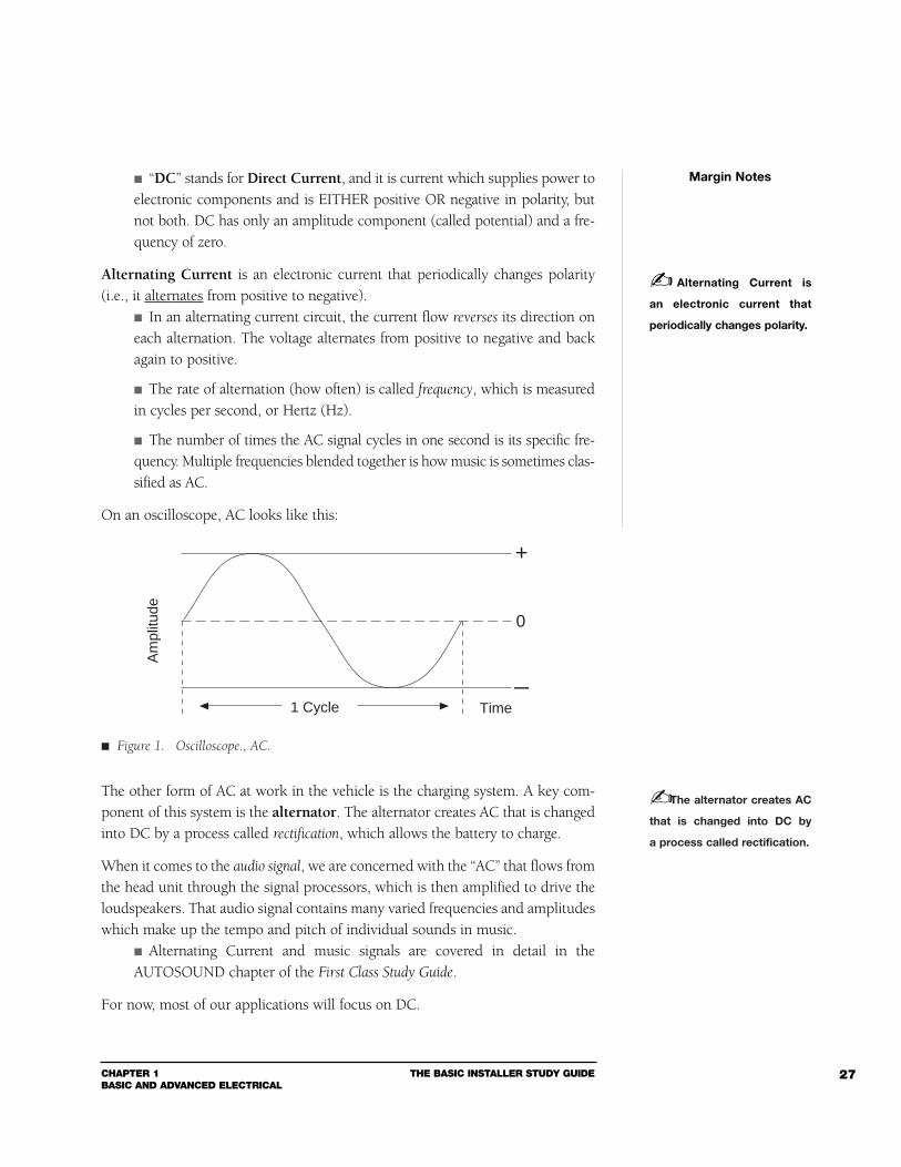
The rate of alternation (how often) is called frequency, which is measuredin cycles per second, or Hertz (Hz).
The number of times the AC signal cycles in one second is its specific fre-quency. Multiple frequencies blended together is how music is sometimes clas-sified as AC.
On an oscilloscope, AC looks like this:
The other form of AC at work in the vehicle is the charging system. A key com-ponent of this system is the alternator. The alternator creates AC that is changedinto DC by a process called rectification, which allows the battery to charge.
When it comes to the audio signal, we are concerned with the “AC” that flows fromthe head unit through the signal processors, which is then amplified to drive theloudspeakers. That audio signal contains many varied frequencies and amplitudeswhich make up the tempo and pitch of individual sounds in music.
Alternating Current and music signals are covered in detail in theAUTOSOUND chapter of the First Class Study Guide.
For now, most of our applications will focus on DC.
Margin Notes
Alternating Current is
an electronic current that
periodically changes polarity.
+
0
—1 Cycle
Am
plitu
de
Time
The alternator creates AC
that is changed into DC by
a process called rectification.
Figure 1. Oscilloscope., AC.
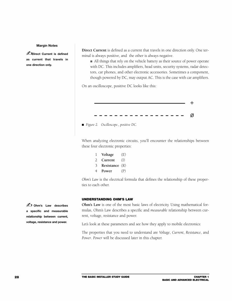
Direct Current is defined as a current that travels in one direction only. One ter-minal is always positive, and the other is always negative.
All things that rely on the vehicle battery as their source of power operatewith DC. This includes amplifiers, head units, security systems, radar detec-tors, car phones, and other electronic accessories. Sometimes a component,though powered by DC, may output AC. This is the case with car amplifiers.
On an oscilloscope, positive DC looks like this:
When analyzing electronic circuits, you’ll encounter the relationships betweenthese four electronic properties:
1 Voltage (E)2 Current (I)3 Resistance (R)4 Power (P)
Ohm’s Law is the electrical formula that defines the relationship of these proper-ties to each other.
UNDERSTANDING OHM’S LAW
Ohm’s Law is one of the most basic laws of electricity. Using mathematical for-mulas, Ohm’s Law describes a specific and measurable relationship between cur-rent, voltage, resistance and power.
Let’s look at these parameters and see how they apply to mobile electronics:
The properties that you need to understand are Voltage, Current, Resistance, andPower. Power will be discussed later in this chapter.
THE BASIC INSTALLER STUDY GUIDE CHAPTER 1BASIC AND ADVANCED ELECTRICAL
28
Margin Notes
Direct Current is defined
as current that travels in
one direction only.
+
ø
Ohm’s Law describes
a specific and measurable
relationship between current,
voltage, resistance and power.
Figure 2. Oscilloscope., positive DC.
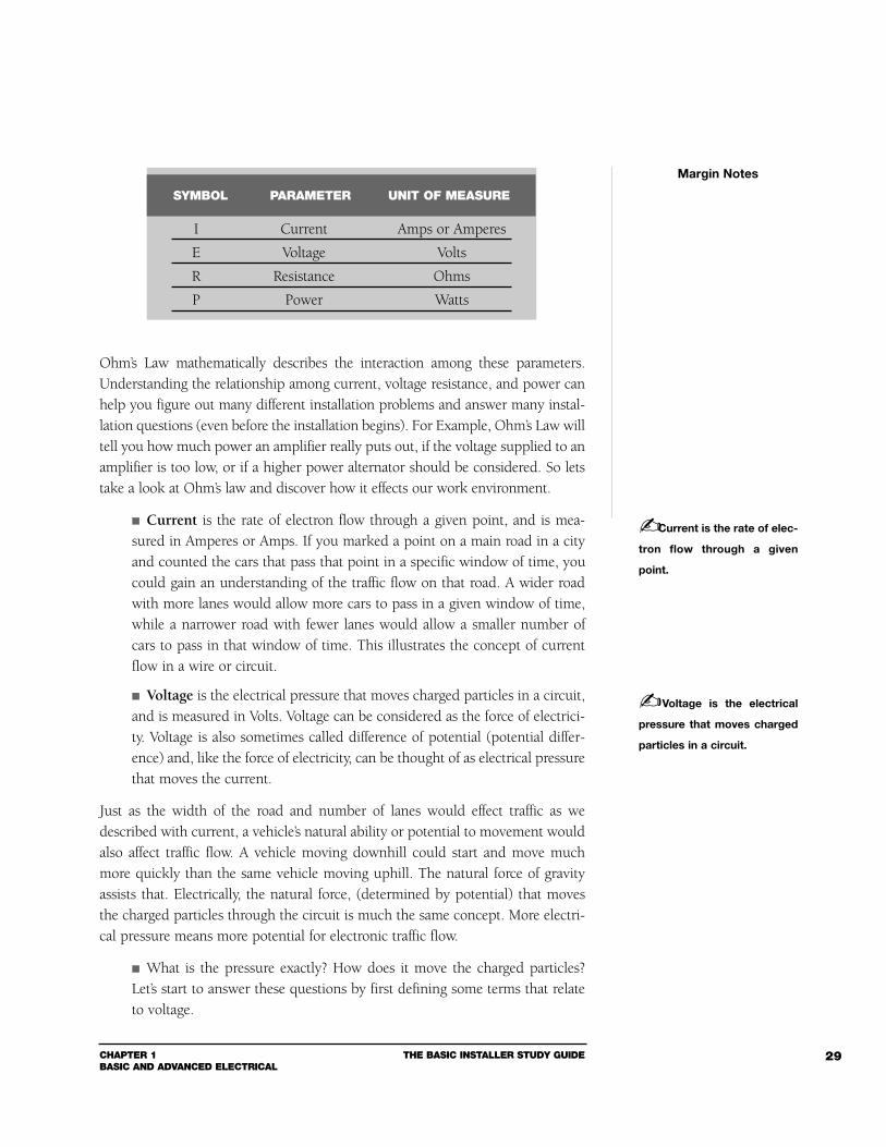
Ohm’s Law mathematically describes the interaction among these parameters.Understanding the relationship among current, voltage resistance, and power canhelp you figure out many different installation problems and answer many instal-lation questions (even before the installation begins). For Example, Ohm’s Law willtell you how much power an amplifier really puts out, if the voltage supplied to anamplifier is too low, or if a higher power alternator should be considered. So letstake a look at Ohm’s law and discover how it effects our work environment.
Current is the rate of electron flow through a given point, and is mea-sured in Amperes or Amps. If you marked a point on a main road in a cityand counted the cars that pass that point in a specific window of time, youcould gain an understanding of the traffic flow on that road. A wider roadwith more lanes would allow more cars to pass in a given window of time,while a narrower road with fewer lanes would allow a smaller number ofcars to pass in that window of time. This illustrates the concept of currentflow in a wire or circuit.
Voltage is the electrical pressure that moves charged particles in a circuit,and is measured in Volts. Voltage can be considered as the force of electrici-ty. Voltage is also sometimes called difference of potential (potential differ-ence) and, like the force of electricity, can be thought of as electrical pressurethat moves the current.
Just as the width of the road and number of lanes would effect traffic as wedescribed with current, a vehicle’s natural ability or potential to movement wouldalso affect traffic flow. A vehicle moving downhill could start and move muchmore quickly than the same vehicle moving uphill. The natural force of gravityassists that. Electrically, the natural force, (determined by potential) that movesthe charged particles through the circuit is much the same concept. More electri-cal pressure means more potential for electronic traffic flow.
What is the pressure exactly? How does it move the charged particles?Let’s start to answer these questions by first defining some terms that relateto voltage.
CHAPTER 1BASIC AND ADVANCED ELECTRICAL
THE BASIC INSTALLER STUDY GUIDE 29
Margin Notes
Current is the rate of elec-
tron flow through a given
point.
Voltage is the electrical
pressure that moves charged
particles in a circuit.
I Current Amps or Amperes
E Voltage Volts
R Resistance Ohms
P Power Watts
SYMBOL PARAMETER UNIT OF MEASURE
THE BASIC INSTALLER STUDY GUIDE CHAPTER 1BASIC AND ADVANCED ELECTRICAL
30
Charge — or electrical charge is the fundamental unit for an amount ofelectricity. Symbolized (Q).
Polarity — in an electrical circuit there are two different polarities: elec-trons posses a negative charge while protons posses a positive charge. It canalso be said that an electron has a negative polarity and a proton has a pos-itive polarity.
Potential - refers to the ability to do work.
Now with these definitions let’s discuss some actions. Like charges repel - two negatively charged particles held together willrepel or want to move away from one another. Likewise, two positivelycharged particles held together will repel or want to move away from oneanother.
Unlike charges attract - when two unlike charges are brought close togetherthey will attract or try to move toward each other.
These two reactions are proof of an electric field. Since potential is the ability ofthe charges to do work, it’s the difference of potential (using the natural ability toattract and repel) that allows the current to move and do work.
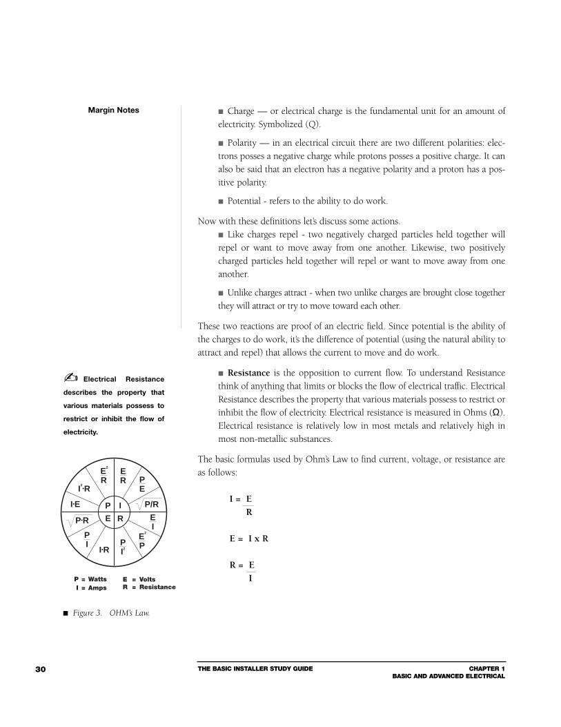
Resistance is the opposition to current flow. To understand Resistancethink of anything that limits or blocks the flow of electrical traffic. ElectricalResistance describes the property that various materials possess to restrict orinhibit the flow of electricity. Electrical resistance is measured in Ohms (Ω).Electrical resistance is relatively low in most metals and relatively high inmost non-metallic substances.
The basic formulas used by Ohm’s Law to find current, voltage, or resistance areas follows:
I = ER
E = I x R
R = EI
Margin Notes
Electrical Resistance
describes the property that
various materials possess to
restrict or inhibit the flow of
electricity.
P I
E R
I•R
PE
PI2
ER
E2
R
PI
EI
E2
P
P•R
I•E
I2•R
P = WattsI = Amps
P/R
E = VoltsR = Resistance
Figure 3. OHM’s Law.
CHAPTER 1BASIC AND ADVANCED ELECTRICAL
THE BASIC INSTALLER STUDY GUIDE 31
According to Ohm’s Law:
If you want to find… and you know… then the math is…
Current (I) Resistance (R) and Voltage (E) E ÷ R = I
Current (I) Power (P) and Voltage (E) P ÷ E = I
Current (I) Power (P) and Resistance (R) (Sq.Rt.) √ P ÷ R = I
Voltage (E) Power (P) and Resistance (R) (Sq.Rt.) √ P x R = E
Voltage (E) Current (I) and Resistance (R) I x R = E
Voltage (E) Current (I) and Power (P) P ÷ I = E
Resistance (R) Current (I) and Voltage (E) E ÷ I = R
Resistance (R) Current (I) and Power (P) P ÷ I2= R
Resistance (R) Voltage (E) and Power (P) E2÷ P = R
Power (P) Current (I) and Voltage (E) E x I = P
Power (P) Current (I) and Resistance (R) R x I2
= P
Power (P) Resistance (R) and Voltage (E) E2÷ R = P
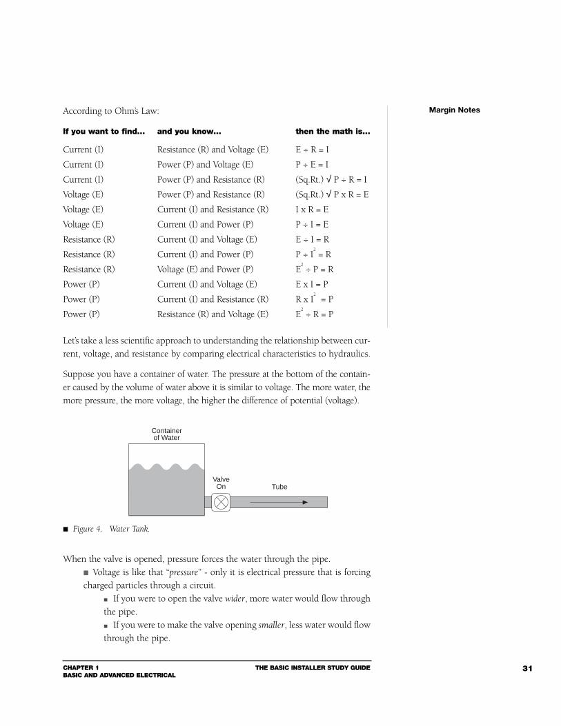
Let’s take a less scientific approach to understanding the relationship between cur-rent, voltage, and resistance by comparing electrical characteristics to hydraulics.
Suppose you have a container of water. The pressure at the bottom of the contain-er caused by the volume of water above it is similar to voltage. The more water, themore pressure, the more voltage, the higher the difference of potential (voltage).
When the valve is opened, pressure forces the water through the pipe. Voltage is like that “pressure” - only it is electrical pressure that is forcingcharged particles through a circuit.
If you were to open the valve wider, more water would flow throughthe pipe. If you were to make the valve opening smaller, less water would flowthrough the pipe.
Margin Notes
Containerof Water
ValveOn Tube
Figure 4. Water Tank.

THE BASIC INSTALLER STUDY GUIDE CHAPTER 1BASIC AND ADVANCED ELECTRICAL
32
This increase and decrease in the rate of water flow is comparable to the idea ofcurrent, but remember that current is the rate of electrons that flow through aconductor.
In addition, if you were to decrease the size of the pipe or bend it slightly, the rateof water flow would decrease because you would be increasing the resistance.
This limitation in flow volume is similar to electrical resistance,which restricts the flow of electrons.
The relationship between current, voltage, and resistance is similar to the con-tainer of water - change one parameter while leaving another alone and the thirdhas to change. It will always change according to Ohm’s law, which is the realbeauty in knowing this concept.
Understanding the relationship between current, voltage, and resistance can helpyou figure out many different installation problems.
Ohm’s Law will tell you things such as: How much power an amplifier really puts out. If the voltage supplied to an amplifier is too low. If a higher output alternator should be considered.
Let’s say, for example, that you’re powering up a high wattage audio system, butyou choose a wire that’s too small to supply the current required by the system.The resistance in the wire will develop an unwanted voltage drop across it (E = I x R) when the amplifiers draw power. Amplifiers operating with low volt-age may overheat, motorboat, or fail.
An easy way to memorize Ohm’s Law is to use the Ohm’s Law Pie Chart. Simply “coverup” the letter you wish to find the value of and carry out the remaining formula.
Here’s another example of how useful Ohm’s Law can be in every day installations: Suppose you have a resistor with a known value of 8 Ohms (R = 8), andyou know the current value that flows through the resistor is 1 Amp (I = 2).What is the voltage across the resistor?
Simply apply Ohm’s Law:
R = 8I = 2
E = I x RE = 2 x 8
E = 16 Volts
Margin Notes
E
I R
Figure 5. OHM’s Law PieChart.
CHAPTER 1BASIC AND ADVANCED ELECTRICAL
THE BASIC INSTALLER STUDY GUIDE 33
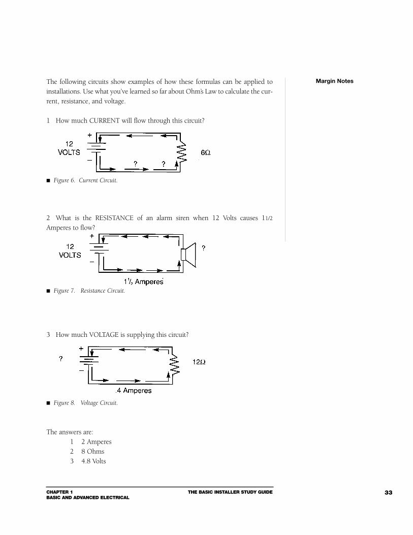
The following circuits show examples of how these formulas can be applied toinstallations. Use what you’ve learned so far about Ohm’s Law to calculate the cur-rent, resistance, and voltage.
1 How much CURRENT will flow through this circuit?
2 What is the RESISTANCE of an alarm siren when 12 Volts causes 11/2
Amperes to flow?
3 How much VOLTAGE is supplying this circuit?
The answers are:1 2 Amperes2 8 Ohms3 4.8 Volts
Margin Notes
Figure 7. Resistance Circuit.
Figure 8. Voltage Circuit.
Figure 6. Current Circuit.
THE BASIC INSTALLER STUDY GUIDE CHAPTER 1BASIC AND ADVANCED ELECTRICAL
34
Ohm’s Law is also very practical to know when you’re trying to calculate effective
resistance. Effective resistance is the “calculated” resistance that a device presents to acircuit while it is operating.
Knowing how to apply Ohm’s Law to determine resistance is practical because it’sfairly easy to use a VOM (Volt Ohm Meter) to measure current and voltage, butyou cannot directly measure resistance in a live circuit.
For example, if you have an amplifier that draws 50 Amps, with an applied volt-age of 12 Volts, for full power output with both channels driven into a 4 Ohmload. How would you determine the effective resistance of the amplifier by apply-ing Ohm’s Law?
Since we know that I = 50 Amps, and E = 12 Volts, we can manipulate Ohm’s Lawso that R is the isolated variable.
Simply divide both sides of the equation by I:
E = I x R
E = I x RI I
R = EI
Now, insert the known values into the formula:
R eff = 12V50A
R eff = 0.24 Ohms
ELECTRICAL POWER
Ohm’s Law relates a fourth circuit parameter - Power. Electrical POWER is the conversion of energy into work over a certainperiod of time, and a watt represents the rate over time that the energy isconverted. It’s the result of the collective work of current, voltage, and resis-tance. The last parameter, “P”, allows you to determine how much a systemcan produce, how many amps it will draw, and therefore what gauge wireand fuse size is needed. Power determines supply and demand.
Margin Notes
Power is the conversion
of energy into work over
a certain period of time.
Effective resistance is the
“calculated” resistance that a
device presents to a circuit
while it is operating.
A watt represents the rate
over time that the energy is
converted.
CHAPTER 1BASIC AND ADVANCED ELECTRICAL
THE BASIC INSTALLER STUDY GUIDE 35
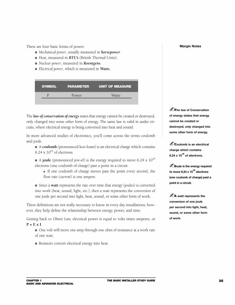
There are four basic forms of power: Mechanical power, usually measured in horsepower. Heat, measured in BTU’s (British Thermal Units). Nuclear power, measured in Roentgens. Electrical power, which is measured in Watts.
The law of conservation of energy states that energy cannot be created or destroyed,only changed into some other form of energy. The same law is valid in audio cir-cuits, where electrical energy is being converted into heat and sound.
In more advanced studies of electronics, you’ll come across the terms coulomband joule.
A coulomb (pronounced koo-loam) is an electrical charge which contains6.24 x 1018 of electrons.
A joule (pronounced jew-el) is the energy required to move 6.24 x 10¹⁸
electrons (one coulomb of charge) past a point in a circuit. If one coulomb of charge moves past the point every second, theflow rate (current) is one ampere.
Since a watt represents the rate over time that energy (joules) is convertedinto work (heat, sound, light, etc.), then a watt represents the conversion ofone joule per second into light, heat, sound, or some other form of work.
These definitions are not really necessary to know in every day installations; how-ever, they help define the relationship between energy, power, and time.
Getting back to Ohm’s Law, electrical power is equal to volts times amperes, or P = E x I.
One volt will move one amp through one ohm of resistance at a work rateof one watt.
Resistors convert electrical energy into heat.
Margin Notes
Coulomb is an electrical
charge which contains
6.24 x 10¹⁸
of electrons.
P Power Watts
SYMBOL PARAMETER UNIT OF MEASURE
Joule is the energy required
to move 6.24 x 10¹⁸
electrons
(one coulomb of charge) past a
point in a circuit.
A watt represents the
conversion of one joule
per second into light, heat,
sound, or some other form
of work.
The law of Conservation
of energy states that energy
cannot be created or
destroyed, only changed into
some other form of energy.
THE BASIC INSTALLER STUDY GUIDE CHAPTER 1BASIC AND ADVANCED ELECTRICAL
36
Remember that amperage is current flow per second, and therefore, a watt is ratedin seconds.
Since power equals: E x I, we know from Ohm’s Law thatE = I x R, P = I x R x I.
This is the formula we will use to figure out the power (wattage) for mostof our DC applications.
Here are some more ways Ohm’s Law can help you figure out different situations(in addition, see the full Ohm’s Law pie chart in the back of this book):
How would you find the total current (I) of an amplifier at the electricalsystem’s idle voltage?
Simply divide the amplifier’s total root mean square (rms) wattage (P) bythe vehicle’s idle voltage (E).
In a system with 250 Watts rms total audio output power, (125 Watts rms/channel into 4 Ohms) and an electrical system with a12.6VDC, the equation would look like this:
250 = 19.84 Amps12.6
This can appear to be complicated - but if you focus on each element in the equa-tion, then it’s easy to understand.
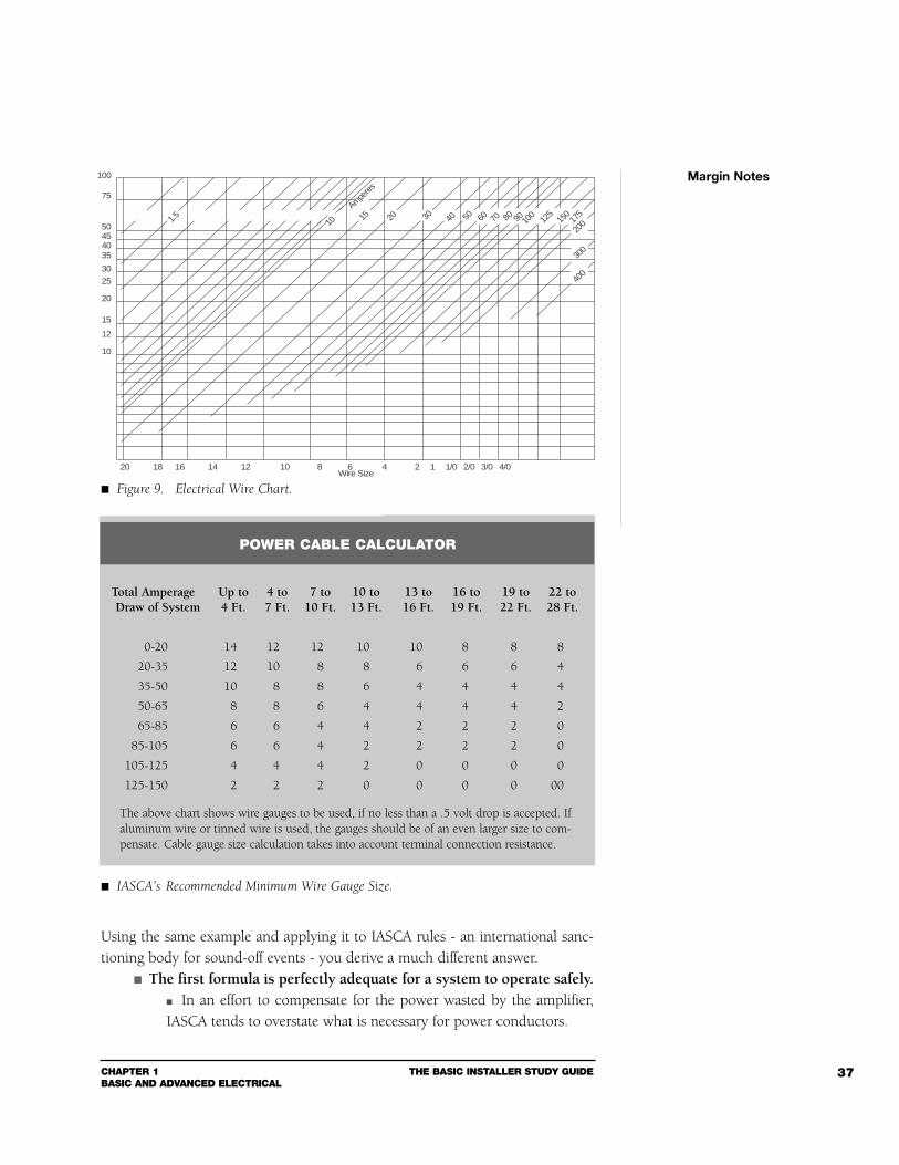
Here’s why it is important that you understand this equation: It “tells” you what size wire to run from the battery to the amplifiers.
If the amplifiers are in the trunk. You have a 15-foot cable run. According to Figure 9, a #10 American Wire Gauge (AWG) cable isnecessary to adequately power up this system.
Ohm’s Law is indeed a very helpful tool to have in the bay.
Margin Notes
Using the same example and applying it to IASCA rules - an international sanc-tioning body for sound-off events - you derive a much different answer.
The first formula is perfectly adequate for a system to operate safely. In an effort to compensate for the power wasted by the amplifier,IASCA tends to overstate what is necessary for power conductors.
CHAPTER 1BASIC AND ADVANCED ELECTRICAL
THE BASIC INSTALLER STUDY GUIDE 37
Margin Notes
1.5 2015 30 40 5010
300
400
20 18 16 14 12 10 8 6 4 2 1 1/0 2/0 3/0 4/0
100
75
50454035
30
25
20
15
12
10
Wire Size
Amperes
175
150
125
10090807060
200
POWER CABLE CALCULATOR
Total Amperage Up to 4 to 7 to 10 to 13 to 16 to 19 to 22 toDraw of System 4 Ft. 7 Ft. 10 Ft. 13 Ft. 16 Ft. 19 Ft. 22 Ft. 28 Ft.
0-20 14 12 12 10 10 8 8 8
20-35 12 10 8 8 6 6 6 4
35-50 10 8 8 6 4 4 4 4
50-65 8 8 6 4 4 4 4 2
65-85 6 6 4 4 2 2 2 0
85-105 6 6 4 2 2 2 2 0
105-125 4 4 4 2 0 0 0 0
125-150 2 2 2 0 0 0 0 00
The above chart shows wire gauges to be used, if no less than a .5 volt drop is accepted. Ifaluminum wire or tinned wire is used, the gauges should be of an even larger size to com-pensate. Cable gauge size calculation takes into account terminal connection resistance.
Figure 9. Electrical Wire Chart.
IASCA’s Recommended Minimum Wire Gauge Size.
THE BASIC INSTALLER STUDY GUIDE CHAPTER 1BASIC AND ADVANCED ELECTRICAL
38
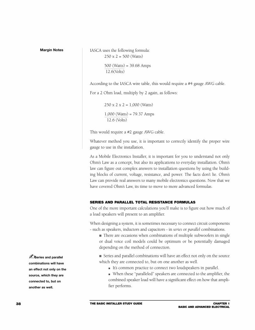
IASCA uses the following formula:250 x 2 = 500 (Watts)
500 (Watts) = 39.68 Amps12.6(Volts)
According to the IASCA wire table, this would require a #4 gauge AWG cable.
For a 2 Ohm load, multiply by 2 again, as follows:
250 x 2 x 2 = 1,000 (Watts)
1,000 (Watts) = 79.37 Amps12.6 (Volts)
This would require a #2 gauge AWG cable.
Whatever method you use, it is important to correctly identify the proper wiregauge to use in the installation.
As a Mobile Electronics Installer, it is important for you to understand not onlyOhm’s Law as a concept, but also its applications to everyday installation. Ohm’slaw can figure out complex answers to installation questions by using the build-ing blocks of current, voltage, resistance, and power. The facts don’t lie. Ohm’sLaw can provide real answers to many mobile electronics questions. Now that wehave covered Ohm’s Law, its time to move to more advanced formulas.
SERIES AND PARALLEL TOTAL RESISTANCE FORMULAS
One of the more important calculations you’ll make is to figure out how much ofa load speakers will present to an amplifier.
When designing a system, it is sometimes necessary to connect circuit components- such as speakers, inductors and capacitors - in series or parallel combinations.
There are occasions when combinations of multiple subwoofers in singleor dual voice coil models could be optimum or be potentially damageddepending on the method of connection.
Series and parallel combinations will have an effect not only on the sourcewhich they are connected to, but on one another as well.
It’s common practice to connect two loudspeakers in parallel. When these “paralleled” speakers are connected to the amplifier, thecombined speaker load will have a significant effect on how that ampli-fier performs.
Margin Notes
Series and parallel
combinations will have
an effect not only on the
source, which they are
connected to, but on
another as well.
CHAPTER 1BASIC AND ADVANCED ELECTRICAL
THE BASIC INSTALLER STUDY GUIDE 39
Therefore, understanding how series and parallel circuit relationships work isanother useful tool, especially when you’re building crossover networks, installingmultiple subwoofers, or performing system analysis.
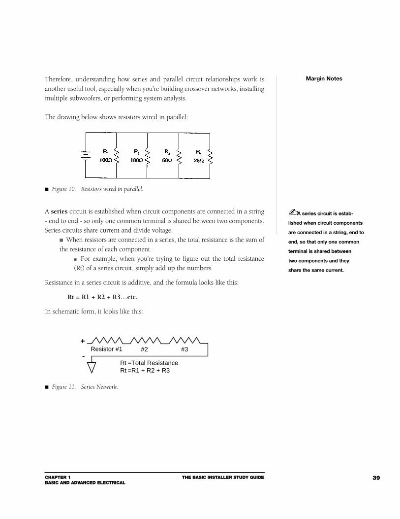
The drawing below shows resistors wired in parallel:
A series circuit is established when circuit components are connected in a string- end to end - so only one common terminal is shared between two components.Series circuits share current and divide voltage.
When resistors are connected in a series, the total resistance is the sum ofthe resistance of each component.
For example, when you’re trying to figure out the total resistance(Rt) of a series circuit, simply add up the numbers.
Resistance in a series circuit is additive, and the formula looks like this:
Rt = R1 + R2 + R3…etc.
In schematic form, it looks like this:
Margin Notes
A series circuit is estab-
lished when circuit components
are connected in a string, end to
end, so that only one common
terminal is shared between
two components and they
share the same current.
+ Resistor #1
-#2 #3
Rt =Total ResistanceRt =R1 + R2 + R3
Figure 10. Resistors wired in parallel.
Figure 11. Series Network.
THE BASIC INSTALLER STUDY GUIDE CHAPTER 1BASIC AND ADVANCED ELECTRICAL
40
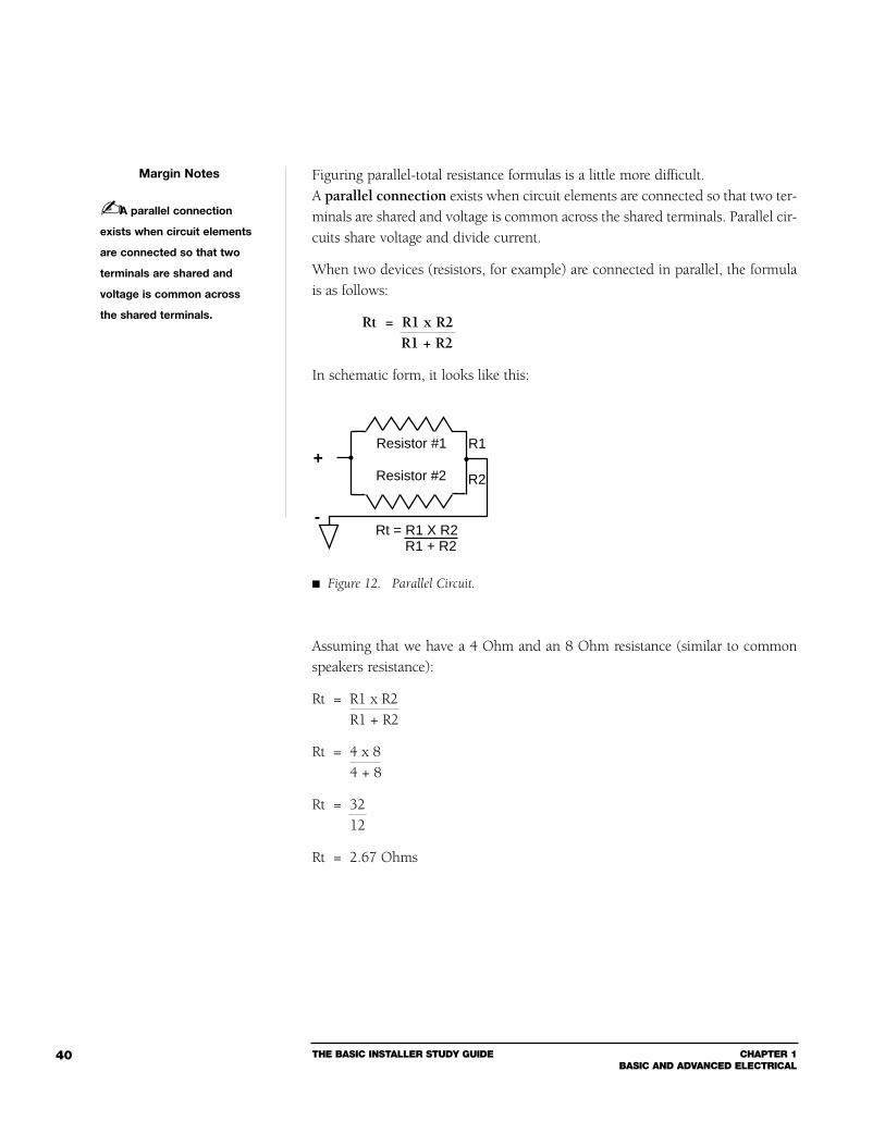
Figuring parallel-total resistance formulas is a little more difficult.A parallel connection exists when circuit elements are connected so that two ter-minals are shared and voltage is common across the shared terminals. Parallel cir-cuits share voltage and divide current.
When two devices (resistors, for example) are connected in parallel, the formulais as follows:
Rt = R1 x R2R1 + R2
In schematic form, it looks like this:
Assuming that we have a 4 Ohm and an 8 Ohm resistance (similar to commonspeakers resistance):
Rt = R1 x R2R1 + R2
Rt = 4 x 84 + 8
Rt = 3212
Rt = 2.67 Ohms
Margin Notes
+
-
Resistor #1
Resistor #2
Rt = R1 X R2R1 + R2
R2
R1
A parallel connection
exists when circuit elements
are connected so that two
terminals are shared and
voltage is common across
the shared terminals.
Figure 12. Parallel Circuit.
CHAPTER 1BASIC AND ADVANCED ELECTRICAL
THE BASIC INSTALLER STUDY GUIDE 41
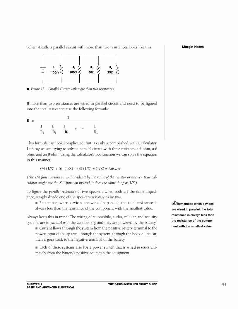
Schematically, a parallel circuit with more than two resistances looks like this:
If more than two resistances are wired in parallel circuit and need to be figuredinto the total resistance, use the following formula:
1R =
1 1 1 + … 1R1 R2 R3 RN
This formula can look complicated, but is easily accomplished with a calculator.Let’s say we are trying to solve a parallel circuit with three resistors: a 4 ohm, a 6ohm, and an 8 ohm. Using the calculator’s 1/X function we can solve the equationin this manner.
(4) (1/X) + (6) (1/X) + (8) (1/X) = (1/X) = Answer
(The 1/X function takes 1 and divides it by the value of the resistor or answer. Your cal-
culator might use the X-1 function instead, it does the same thing as 1/X.)
To figure the parallel resistance of two speakers when both are the same imped-ance, simply divide one of the speaker’s resistances by two.
Remember, when devices are wired in parallel, the total resistance isalways less than the resistance of the component with the smallest value.
Always keep this in mind: The wiring of automobile, audio, cellular, and securitysystems are in parallel with the car’s battery, and they are powered by the battery.
Current flows through the system from the positive battery terminal to thepower input of the system, through the system, through the body of the car,then it goes back to the negative terminal of the battery.
Each of these systems also has a power switch that is wired in series ulti-mately from the battery’s positive source to the equipment.
Margin Notes
Remember, when devices
are wired in parallel, the total
resistance is always less than
the resistance of the compo-
nent with the smallest value.
Figure 13. Parallel Circuit with more than two resistances.
THE BASIC INSTALLER STUDY GUIDE CHAPTER 1BASIC AND ADVANCED ELECTRICAL
42
Series and Parallel Capacitors (to clarify the one exception to the rule)
Series Inductors and Resistors use the above formula for SERIES WIRING.The same SERIES FORMULA applies to PARALLEL CAPACITORS.
Parallel Inductors and Resistors use the above formula for PARALLELWIRING. The same PARALLEL FORMULA applies to SERIES CAPACITORS.
KIRCHOFF’S VOLTAGE LAW
We’ve seen from some of the previous examples that single resistor circuit analy-sis can be figured out by using Ohm’s Law. More complicated circuit analysis,however, requires an understanding of another important electrical law -Kirchoff’s Voltage Law (KVL).
Kirchoff’s Voltage Law (KVL) states that the voltage applied to a DC series cir-cuit must equal the sum of the voltage drops within the circuit.
Vt = VR1 + VR2 + VR3.........( + Vn)
Where: Vt is the applied voltage, VR1 is the voltage drop across resistor #1, VR2 is the voltage
drop across resistor #2, etc. and Vn is the remaining voltage after all of the measured drops.
In other words, if you add up all the voltage drops across each individual com-ponent, the total equals the applied voltage.
This means that one volt dropped through wiring or connectors in a sys-tem will reduce the voltage to the equipment by one volt.
This is especially true in practical applications, for example in multiple speaker orsubwoofer (single and dual voice coil) installations.
Each speaker wired down the line to the same power cable would get alittle less power to it than the one before it.
Often overlooked, even in the simplest of installations, is that one badconnection or poorly crimped terminal can affect the voltage for that seriessection, but not for the whole system. That could explain all kinds of other-wise mysterious speaker behavior.
KIRCHOFF’S CURRENT LAW
Kirchoff’s Voltage Law will help you determine single loop circuits; however, solv-ing parallel circuits which have multiple loops requires the use of Kirchoff’sCurrent Law (KCL):
Margin Notes
Kirchoff’s Voltage Law
(KVL) states that the voltage
applied to a DC series circuit
must equal the sum of the
voltage drops within the
circuit.
CHAPTER 1BASIC AND ADVANCED ELECTRICAL
THE BASIC INSTALLER STUDY GUIDE 43
This law states that the total current entering a point or junction in a cir-cuit must equal the sum of the currents leaving that point or junction.
It = IR1 + IR2 + IR3.........( + In)
Where: It is the total current, IR1 is the sum of current #1, IR2 is the sum of current #2,
etc. and In is the remaining current after all of the other measured currents.
Think of your power and ground connections as one big loop from and to the battery. A heavy gauge ground wire is just as important, if not more so, as the powerwire gauge.
Too small a gauge ground wire will develop a voltage drop whichmay also cause the amplifiers to overheat, motorboat, or fail.
CURRENT FLOW
In the front part of this section, we covered many of the basic and advanced elec-trical laws you will need to know. Before we continue on to electrical components,we need to clarify current flow.
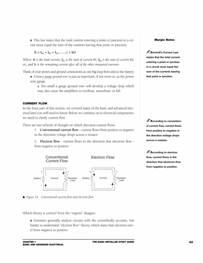
There are two schools of thought on which direction current flows:1 Conventional current flow - current flows from positive to negativein the direction voltage drops across a resistor.
2 Electron flow - current flows in the direction that electrons flow -from negative to positive.
Which theory is correct? Even the “experts” disagree:
Scientists generally analyze circuits with the scientifically accurate, butharder to understand “electron flow” theory, which states that electrons trav-el from negative to positive.
Margin Notes
Kirchoff’s Current Law
states that the total current
entering a point or junction
in a circuit must equal the
sum of the currents leaving
that point or junction.
According to convention-
al current flow, current flows
from positive to negative in
the direction voltage drops
across a resistor.
According to electron
flow, current flows in the
direction that electrons flow
from negative to positive.
ConventionalCurrent Flow
Electron Flow
Current
+
-
+
-
ResistiveLoad
Battery Current
+
-
+
-
ResistiveLoad
Battery
Figure 14. Conventional current flow and electron flow.
THE BASIC INSTALLER STUDY GUIDE CHAPTER 1BASIC AND ADVANCED ELECTRICAL
44
Engineers analyze circuits with “conventional current flow” theory, wherecurrent flows from higher voltage potential to lower voltage potential.
Either method - when properly applied - will result in the same answer when ana-lyzing a circuit.
Section 2Electrical Components
With those formulas in mind, let’s look at some of the electrical components you’llbe using to improve system design and performance.
RESISTORS
For installers, the actual definition of a resistor is not as important as the conceptbehind resistance. For test purposes, however, a resistor is defined as an electri-cal component designed to have a specific resistance (or opposition) to the flowof electrons, measured in ohms.
The concept of resistance was introduced in Section 1. It describes the propertythat some materials posses to restrict the flow of current.
Resistance is generally an undesirable characteristic in mobile electronicswiring.
There are instances where an installer will use a resistor to introduce aspecific resistance.
Resistance can be added to a signal cable to reduce the input signalvoltage to an amplifier. Power resistors can be used to reduce the amount of power to aspeaker (essentially changing the speakers sensitivity) to connect leftand right amplifier outputs into one speaker (center channel, rear monospeakers), or to change the ohm load that a passive crossover sees.
Resistors come in all values and power ratings: The most common values are between .1 and 10 million Ohms, withpower ratings of 1/8, 1/4, & 1/2 Watts for signal work, or 5, 10, 25 and upto 1,000 Watts and higher for power work.
A resistor’s wattage rating indicates how much electrical energy canbe safely converted to heat.
CAUTION: All resistors can produce heat, and you want be sure that this heat doesnot create a fire hazard.
Margin Notes
A resistor is an electrical
component designed to have
a specific resistance (or
opposition) to the flow of
electrons, measured in ohms.
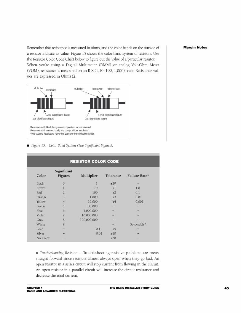
CHAPTER 1BASIC AND ADVANCED ELECTRICAL
THE BASIC INSTALLER STUDY GUIDE 45
Remember that resistance is measured in ohms, and the color bands on the outside ofa resistor indicate its value. Figure 15 shows the color band system of resistors. Usethe Resistor Color Code Chart below to figure out the value of a particular resistor.When you’re using a Digital Multimeter (DMM) or analog Volt-Ohm Meter(VOM), resistance is measured on an R X (1,10, 100, 1,000) scale. Resistance val-ues are expressed in Ohms Ω.
Troubleshooting Resistors - Troubleshooting resistive problems are prettystraight forward since resistors almost always open when they go bad. Anopen resistor in a series circuit will stop current from flowing in the circuit.An open resistor in a parallel circuit will increase the circuit resistance anddecrease the total current.
Margin Notes
1st significant figure
2nd significant figure
1st significant figure
2nd significant figure
MultiplierTolerance Multiplier Tolerance Failure Rate
Resistors with black body are composition. non-insulated.Resistors with colored body are composition. insulated.Wire wound Resistors have the 1st color band double width.
RESISTOR COLOR CODE
SignificantColor Figures Multiplier Tolerance Failure Rate*
Black 0 1 ±20 _
Brown 1 10 ±1 1.0Red 2 100 ±2 0.1Orange 3 1,000 ±3 0.01Yellow 4 10,000 ±4 0.001Green 5 100,000 _ _
Blue 6 1,000,000 _ _
Violet 7 10,000,000 _ _
Gray 8 100,000,000 _ _
White 9 _ Solderable*Gold _ 0.1 ±5 _
Silver _ 0.01 ±10 _
No Color _ ±20 _
Figure 15. Color Band System (Two Significant Figures).
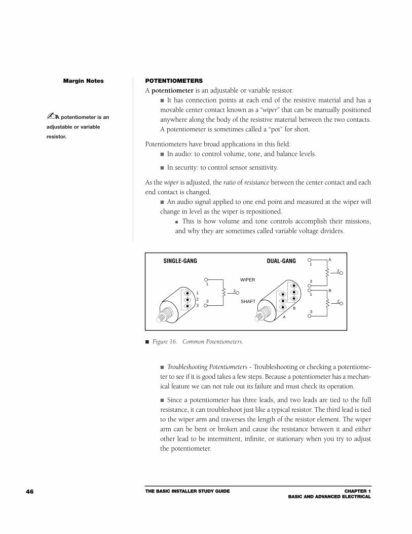
THE BASIC INSTALLER STUDY GUIDE CHAPTER 1BASIC AND ADVANCED ELECTRICAL
46
POTENTIOMETERS
A potentiometer is an adjustable or variable resistor. It has connection points at each end of the resistive material and has amovable center contact known as a “wiper” that can be manually positionedanywhere along the body of the resistive material between the two contacts.A potentiometer is sometimes called a “pot” for short.
Potentiometers have broad applications in this field: In audio: to control volume, tone, and balance levels.
In security: to control sensor sensitivity.
As the wiper is adjusted, the ratio of resistance between the center contact and eachend contact is changed.
An audio signal applied to one end point and measured at the wiper willchange in level as the wiper is repositioned.
This is how volume and tone controls accomplish their missions,and why they are sometimes called variable voltage dividers.
Troubleshooting Potentiometers - Troubleshooting or checking a potentiome-ter to see if it is good takes a few steps. Because a potentiometer has a mechan-ical feature we can not rule out its failure and must check its operation.
Since a potentiometer has three leads, and two leads are tied to the fullresistance, it can troubleshoot just like a typical resistor. The third lead is tiedto the wiper arm and traverses the length of the resistor element. The wiperarm can be bent or broken and cause the resistance between it and eitherother lead to be intermittent, infinite, or stationary when you try to adjustthe potentiometer.
Margin Notes
1
2
3
1
3
2
WIPER
SHAFT
SINGLE-GANG
A
B
DUAL-GANG1
3
2
1
3
2
A
B
A potentiometer is an
adjustable or variable
resistor.
Figure 16. Common Potentiometers.
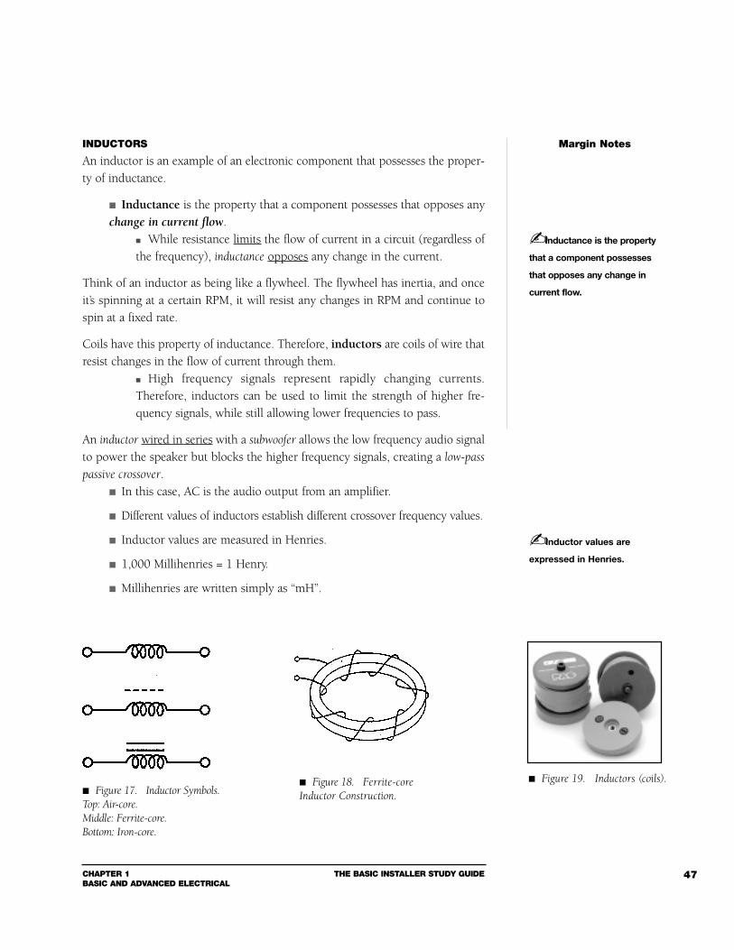
CHAPTER 1BASIC AND ADVANCED ELECTRICAL
THE BASIC INSTALLER STUDY GUIDE 47
INDUCTORS
An inductor is an example of an electronic component that possesses the proper-ty of inductance.
Inductance is the property that a component possesses that opposes anychange in current flow.
While resistance limits the flow of current in a circuit (regardless ofthe frequency), inductance opposes any change in the current.
Think of an inductor as being like a flywheel. The flywheel has inertia, and onceit’s spinning at a certain RPM, it will resist any changes in RPM and continue tospin at a fixed rate.
Coils have this property of inductance. Therefore, inductors are coils of wire thatresist changes in the flow of current through them.
High frequency signals represent rapidly changing currents.Therefore, inductors can be used to limit the strength of higher fre-quency signals, while still allowing lower frequencies to pass.
An inductor wired in series with a subwoofer allows the low frequency audio signalto power the speaker but blocks the higher frequency signals, creating a low-pass
passive crossover. In this case, AC is the audio output from an amplifier.
Different values of inductors establish different crossover frequency values.
Inductor values are measured in Henries.
1,000 Millihenries = 1 Henry.
Millihenries are written simply as “mH”.
Margin Notes
Inductance is the property
that a component possesses
that opposes any change in
current flow.
Inductor values are
expressed in Henries.
Figure 19. Inductors (coils). Figure 17. Inductor Symbols.Top: Air-core.Middle: Ferrite-core.Bottom: Iron-core.
Figure 18. Ferrite-coreInductor Construction.
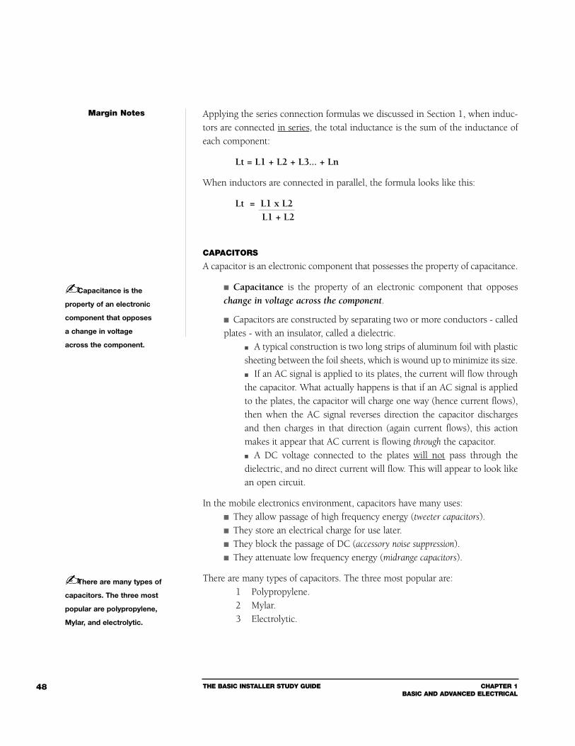
THE BASIC INSTALLER STUDY GUIDE CHAPTER 1BASIC AND ADVANCED ELECTRICAL
48
Applying the series connection formulas we discussed in Section 1, when induc-tors are connected in series, the total inductance is the sum of the inductance ofeach component:
Lt = L1 + L2 + L3... + Ln
When inductors are connected in parallel, the formula looks like this:
Lt = L1 x L2L1 + L2
CAPACITORS
A capacitor is an electronic component that possesses the property of capacitance.
Capacitance is the property of an electronic component that opposeschange in voltage across the component.
Capacitors are constructed by separating two or more conductors - calledplates - with an insulator, called a dielectric.
A typical construction is two long strips of aluminum foil with plasticsheeting between the foil sheets, which is wound up to minimize its size. If an AC signal is applied to its plates, the current will flow throughthe capacitor. What actually happens is that if an AC signal is appliedto the plates, the capacitor will charge one way (hence current flows),then when the AC signal reverses direction the capacitor dischargesand then charges in that direction (again current flows), this actionmakes it appear that AC current is flowing through the capacitor. A DC voltage connected to the plates will not pass through thedielectric, and no direct current will flow. This will appear to look likean open circuit.
In the mobile electronics environment, capacitors have many uses: They allow passage of high frequency energy (tweeter capacitors). They store an electrical charge for use later. They block the passage of DC (accessory noise suppression). They attenuate low frequency energy (midrange capacitors).
There are many types of capacitors. The three most popular are:1 Polypropylene.2 Mylar.3 Electrolytic.
Margin Notes
There are many types of
capacitors. The three most
popular are polypropylene,
Mylar, and electrolytic.
Capacitance is the
property of an electronic
component that opposes
a change in voltage
across the component.
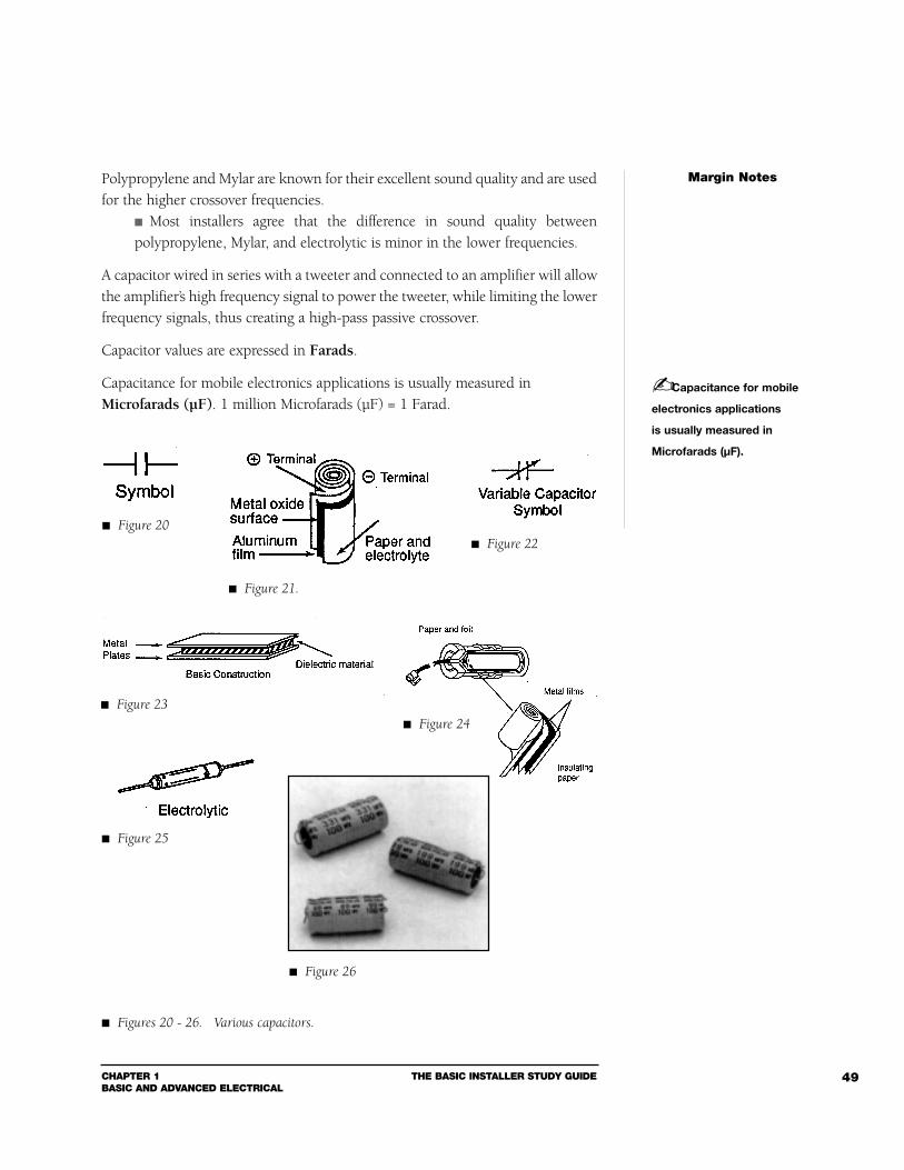
CHAPTER 1BASIC AND ADVANCED ELECTRICAL
THE BASIC INSTALLER STUDY GUIDE 49
Polypropylene and Mylar are known for their excellent sound quality and are usedfor the higher crossover frequencies.
Most installers agree that the difference in sound quality betweenpolypropylene, Mylar, and electrolytic is minor in the lower frequencies.
A capacitor wired in series with a tweeter and connected to an amplifier will allowthe amplifier’s high frequency signal to power the tweeter, while limiting the lowerfrequency signals, thus creating a high-pass passive crossover.
Capacitor values are expressed in Farads.
Capacitance for mobile electronics applications is usually measured inMicrofarads (µF). 1 million Microfarads (µF) = 1 Farad.
Margin Notes
Capacitance for mobile
electronics applications
is usually measured in
Microfarads (µF).
Figure 20
Figure 21.
Figure 22
Figure 23
Figure 24
Figure 25
Figures 20 - 26. Various capacitors.
Figure 26
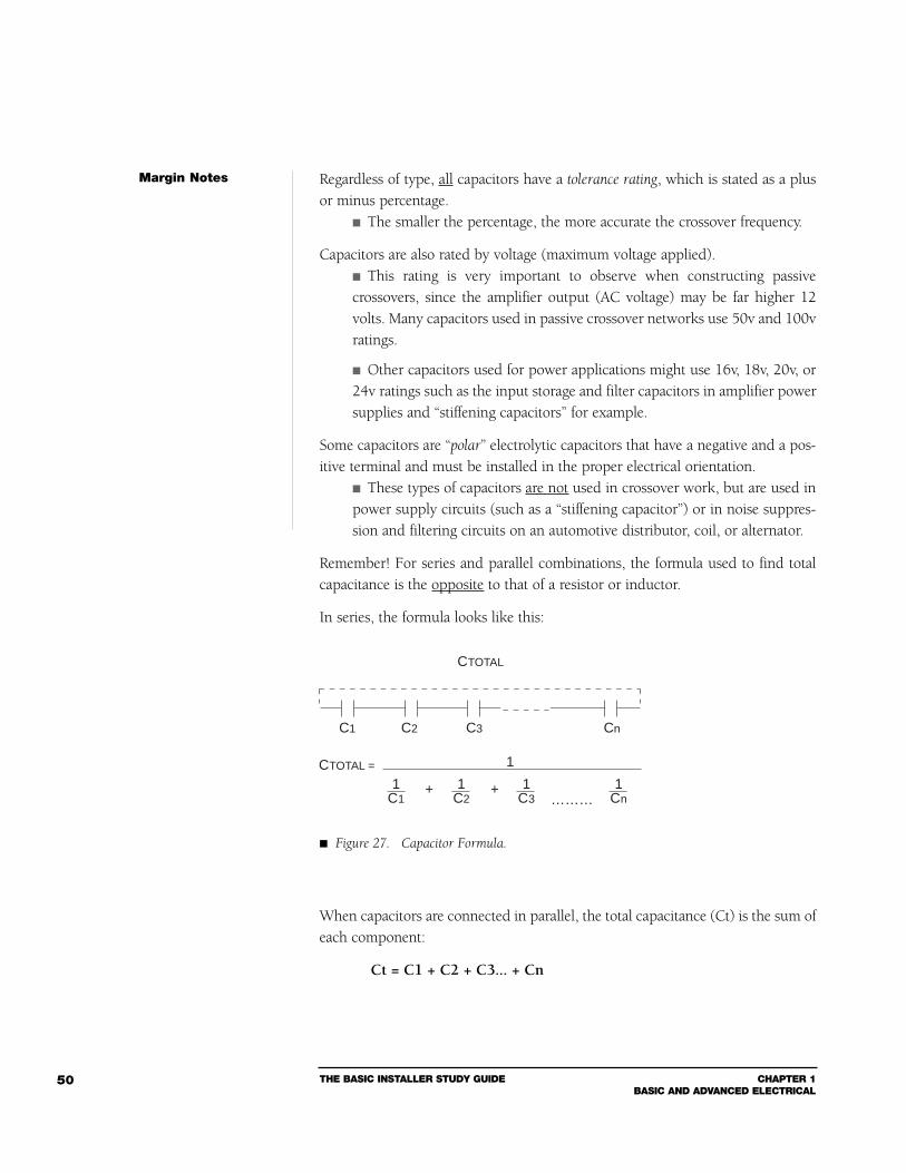
THE BASIC INSTALLER STUDY GUIDE CHAPTER 1BASIC AND ADVANCED ELECTRICAL
50
Regardless of type, all capacitors have a tolerance rating, which is stated as a plusor minus percentage.
The smaller the percentage, the more accurate the crossover frequency.
Capacitors are also rated by voltage (maximum voltage applied). This rating is very important to observe when constructing passivecrossovers, since the amplifier output (AC voltage) may be far higher 12volts. Many capacitors used in passive crossover networks use 50v and 100vratings.
Other capacitors used for power applications might use 16v, 18v, 20v, or24v ratings such as the input storage and filter capacitors in amplifier powersupplies and “stiffening capacitors” for example.
Some capacitors are “polar” electrolytic capacitors that have a negative and a pos-itive terminal and must be installed in the proper electrical orientation.
These types of capacitors are not used in crossover work, but are used inpower supply circuits (such as a “stiffening capacitor”) or in noise suppres-sion and filtering circuits on an automotive distributor, coil, or alternator.
Remember! For series and parallel combinations, the formula used to find totalcapacitance is the opposite to that of a resistor or inductor.
In series, the formula looks like this:
When capacitors are connected in parallel, the total capacitance (Ct) is the sum ofeach component:
Ct = C1 + C2 + C3... + Cn
Margin Notes
CTOTAL
CTOTAL =
C1 C2 C3 Cn
1C1
1C2
1C3
1Cn
1
+ +………
Figure 27. Capacitor Formula.
CHAPTER 1BASIC AND ADVANCED ELECTRICAL
THE BASIC INSTALLER STUDY GUIDE 51
FUSES AND CIRCUIT BREAKERS
If installed properly, a fuse can save you a lot of time and headaches. Think of afuse as cheap insurance.
A fuse is simply a device that contains a wire or strip of metal which isinstalled in series with a power line.
This strip of metal is designed to melt if it receives an excessiveamount of current.
Fuses are used as a safeguard against circuit or system damage. For example, if youhave a customer who is a bit aggressive with the volume control of his stereo sys-tem, you can protect his tweeters from “blowing” by installing a fuse - in series -with the tweeter.
To determine the proper amperage of the fuse, you’ll need to know the ohm loadof the tweeter as well as its continuous or nominal power rating.
The formula to find the amperage of the proper fuse is equal to the squareroot of the continuous power handling, divided by the ohm load of thetweeter.
Amperage = Square root of Continuous Power/Ohm load.
Sometimes you’ll run across a situation where the recommended fuse value ishigher than the largest available fuse.
You could install fuses in a parallel combination, but that can get bulky.
A circuit breaker works better in these situations, because like fuses, theyare designed to blow (or open) when the current becomes excessive.
A circuit breaker is different from a fuse in that it usually can bereset. Circuit breakers that can be reset come as 2 types - ManualResetting or Auto Resetting.
A circuit breaker is a device placed in series with a power line which, when anexcess amount of current is sensed, will open the power connection, thus pro-tecting a circuit or system.
For protection at the battery, use either a fuse or a circuit breaker. The idea behindthese devices is simply to open the circuit before any wires burn.
Margin Notes
A fuse is simply a device
that contains a wire or strip
of metal which is installed in
series with a power line.
A circuit breaker is a
device placed in series with
a power line which, when an
excess amount of current is
sensed, will open the power
connection, thus protecting
a circuit or system.
THE BASIC INSTALLER STUDY GUIDE CHAPTER 1BASIC AND ADVANCED ELECTRICAL
52
Section 3Basic Electrical Troubleshooting
Now that you’re familiar with many of the electrical components used in mobileinstallations, it’s time to discuss common problems that occur when some of thesecomponents fail or are improperly installed.
VOLTAGE DROPS
In Section 1, you learned about resistance and how it opposes the flow of current. When a device in a circuit has resistance, it will convert an amount ofenergy into heat, which results in a certain amount of power loss.
This loss is commonly referred to as a voltage drop. A bad connection or any point of resistance in the power circuit willcause a voltage drop.
A drop in voltage can manifest itself in a variety of ways: Voltage drops result in poor performance, which a customer couldattribute to a particular product.
Often, it has nothing to do with the product, but with the misappli-cation during an installation.
Here’s an example of the multiple possibilities for voltage drops to occur: When a power window is activated, a circuit is completed.
This circuit starts from the positive “+” battery terminal and runsthrough the key switch accessory terminal, the fuse block, and thenthrough the pressed window switch and one window motor lead. It then runs out the other motor lead, through the un-pressed win-dow switch, through the chassis ground and the metal of the vehicle,and finally, through the battery ground strap to the negative terminalof the battery.
In an ideal world, the load on the battery would be determined by the motor’s elec-trical characteristics.
In the real world, the motor determines most of the load unless there is a circuitproblem.
If a switch contact wears, or a connector corrodes, the motor may notreceive the power it requires.
The circuit problem prevents full power from reaching the motor;some of the voltage that would normally go to the motor is lost acrossa weak circuit connection or contact.
Margin Notes
A bad connection or any
point of resistance in the
power circuit will cause a
voltage drop.
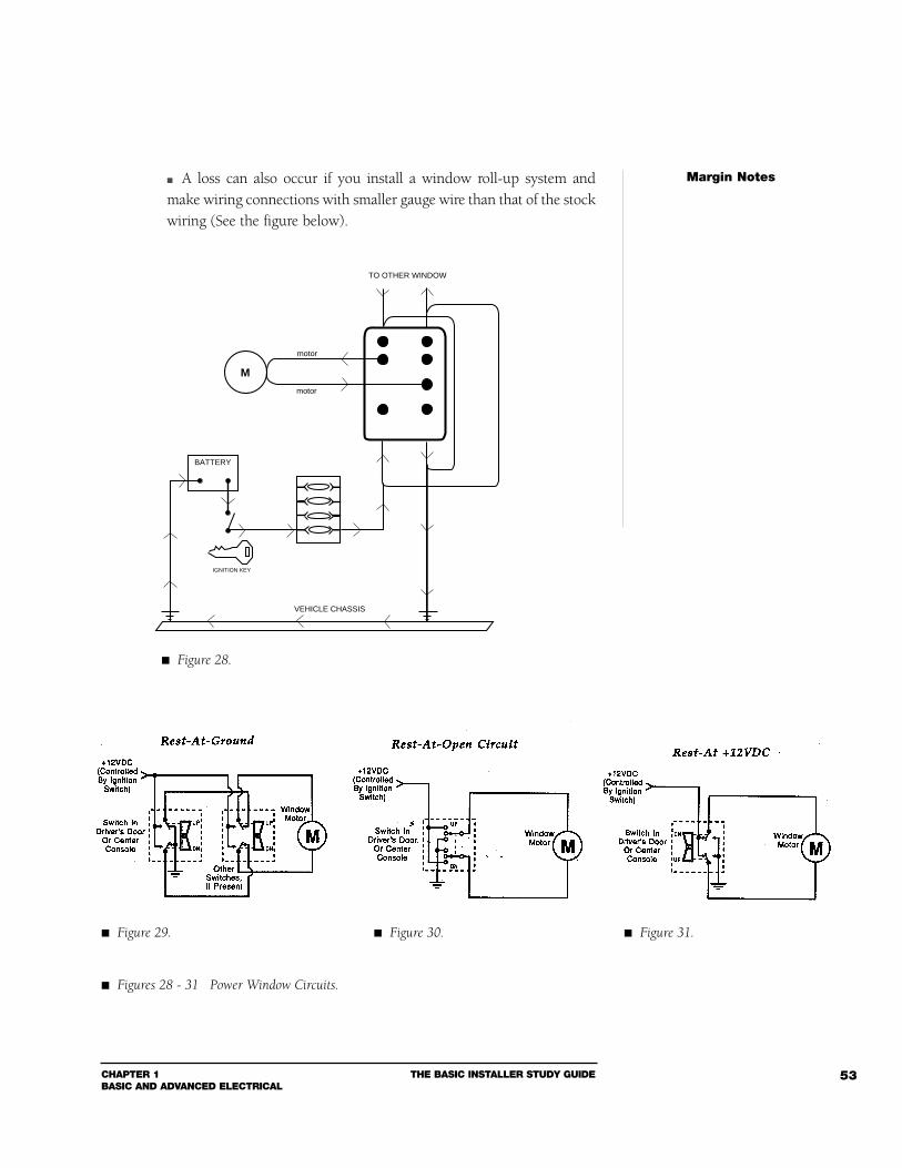
CHAPTER 1BASIC AND ADVANCED ELECTRICAL
THE BASIC INSTALLER STUDY GUIDE 53
A loss can also occur if you install a window roll-up system andmake wiring connections with smaller gauge wire than that of the stockwiring (See the figure below).
Margin Notes
TO OTHER WINDOW
M
VEHICLE CHASSIS
BATTERY
motor
motor
IGNITION KEY
Figure 28.
Figure 29. Figure 30. Figure 31.
Figures 28 - 31 Power Window Circuits.
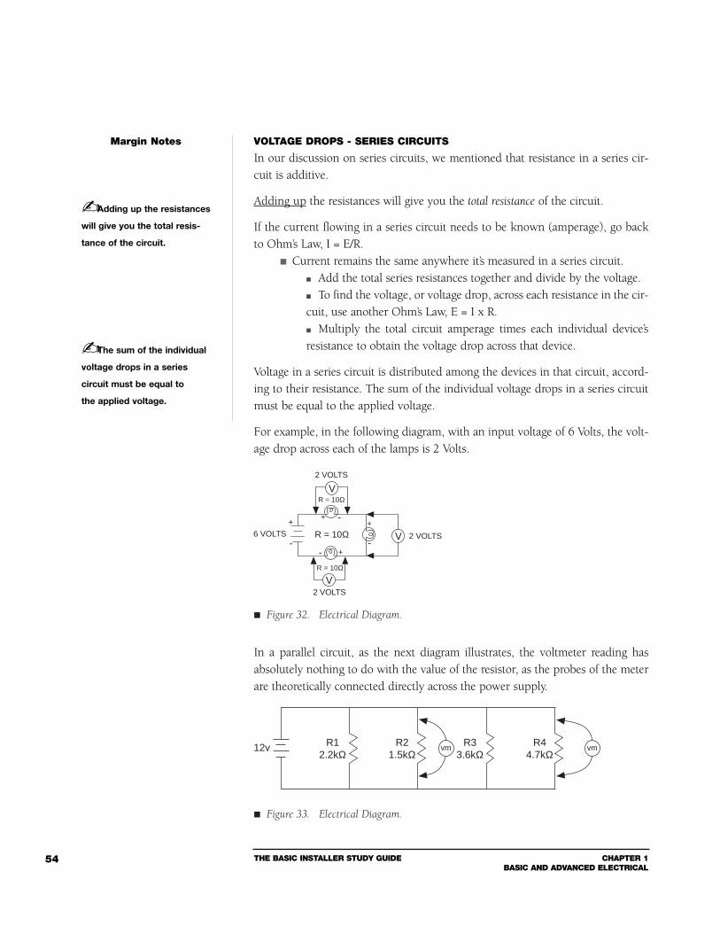
THE BASIC INSTALLER STUDY GUIDE CHAPTER 1BASIC AND ADVANCED ELECTRICAL
54
VOLTAGE DROPS - SERIES CIRCUITS
In our discussion on series circuits, we mentioned that resistance in a series cir-cuit is additive.
Adding up the resistances will give you the total resistance of the circuit.
If the current flowing in a series circuit needs to be known (amperage), go backto Ohm’s Law, I = E/R.
Current remains the same anywhere it’s measured in a series circuit. Add the total series resistances together and divide by the voltage. To find the voltage, or voltage drop, across each resistance in the cir-cuit, use another Ohm’s Law, E = I x R. Multiply the total circuit amperage times each individual device’sresistance to obtain the voltage drop across that device.
Voltage in a series circuit is distributed among the devices in that circuit, accord-ing to their resistance. The sum of the individual voltage drops in a series circuitmust be equal to the applied voltage.
For example, in the following diagram, with an input voltage of 6 Volts, the volt-age drop across each of the lamps is 2 Volts.
In a parallel circuit, as the next diagram illustrates, the voltmeter reading hasabsolutely nothing to do with the value of the resistor, as the probes of the meterare theoretically connected directly across the power supply.
Margin Notes
Adding up the resistances
will give you the total resis-
tance of the circuit.
The sum of the individual
voltage drops in a series
circuit must be equal to
the applied voltage.
V
V
V
+ -+
-+-
+
-
R = 10Ω
R = 10Ω
R = 10Ω
2 VOLTS
2 VOLTS
2 VOLTS
6 VOLTS
Figure 32. Electrical Diagram.
R12.2kΩ
R21.5kΩ
R33.6kΩ
R44.7kΩ
12v vmvm
Figure 33. Electrical Diagram.
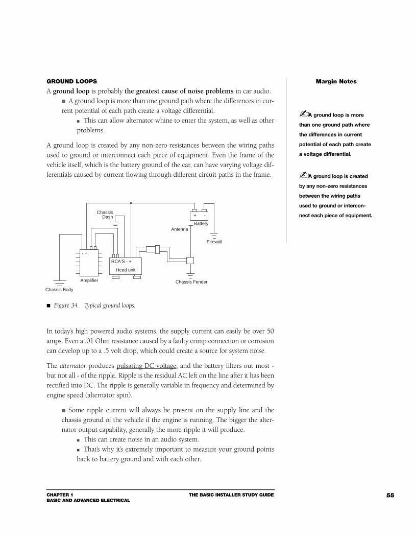
CHAPTER 1BASIC AND ADVANCED ELECTRICAL
THE BASIC INSTALLER STUDY GUIDE 55
GROUND LOOPS
A ground loop is probably the greatest cause of noise problems in car audio. A ground loop is more than one ground path where the differences in cur-rent potential of each path create a voltage differential.
This can allow alternator whine to enter the system, as well as otherproblems.
A ground loop is created by any non-zero resistances between the wiring pathsused to ground or interconnect each piece of equipment. Even the frame of thevehicle itself, which is the battery ground of the car, can have varying voltage dif-ferentials caused by current flowing through different circuit paths in the frame.
In today’s high powered audio systems, the supply current can easily be over 50amps. Even a .01 Ohm resistance caused by a faulty crimp connection or corrosioncan develop up to a .5 volt drop, which could create a source for system noise.
The alternator produces pulsating DC voltage, and the battery filters out most -but not all - of the ripple. Ripple is the residual AC left on the line after it has beenrectified into DC. The ripple is generally variable in frequency and determined byengine speed (alternator spin).
Some ripple current will always be present on the supply line and thechassis ground of the vehicle if the engine is running. The bigger the alter-nator output capability, generally the more ripple it will produce.
This can create noise in an audio system. That’s why it’s extremely important to measure your ground pointsback to battery ground and with each other.
Margin Notes
A ground loop is more
than one ground path where
the differences in current
potential of each path create
a voltage differential.
A ground loop is created
by any non-zero resistances
between the wiring paths
used to ground or intercon-
nect each piece of equipment.
Amplifier
Chassis Body
Head unit
RCA'S - +
Chassis Fender
Antenna
Firewall
Battery
Chassis Dash
- +
+ -
Figure 34. Typical ground loops.
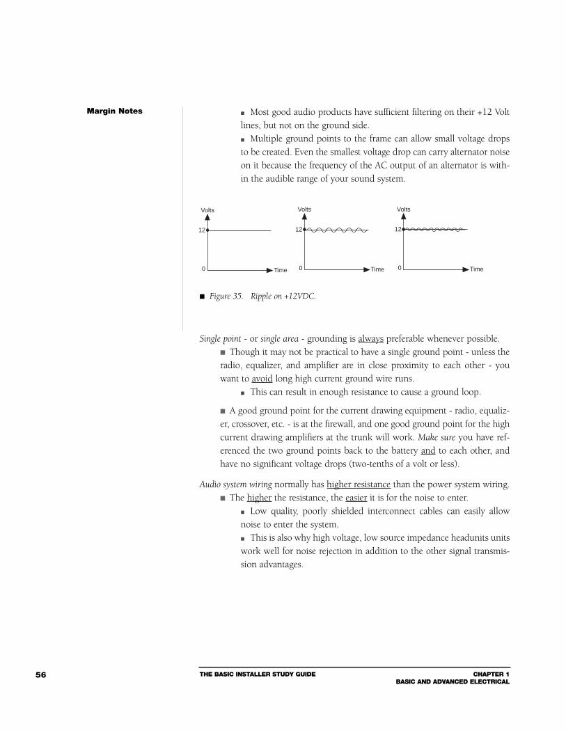
THE BASIC INSTALLER STUDY GUIDE CHAPTER 1BASIC AND ADVANCED ELECTRICAL
56
Most good audio products have sufficient filtering on their +12 Voltlines, but not on the ground side. Multiple ground points to the frame can allow small voltage dropsto be created. Even the smallest voltage drop can carry alternator noiseon it because the frequency of the AC output of an alternator is with-in the audible range of your sound system.
Single point - or single area - grounding is always preferable whenever possible. Though it may not be practical to have a single ground point - unless theradio, equalizer, and amplifier are in close proximity to each other - youwant to avoid long high current ground wire runs.
This can result in enough resistance to cause a ground loop.
A good ground point for the current drawing equipment - radio, equaliz-er, crossover, etc. - is at the firewall, and one good ground point for the highcurrent drawing amplifiers at the trunk will work. Make sure you have ref-erenced the two ground points back to the battery and to each other, andhave no significant voltage drops (two-tenths of a volt or less).
Audio system wiring normally has higher resistance than the power system wiring. The higher the resistance, the easier it is for the noise to enter.
Low quality, poorly shielded interconnect cables can easily allownoise to enter the system. This is also why high voltage, low source impedance headunits unitswork well for noise rejection in addition to the other signal transmis-sion advantages.
Margin Notes
Volts
Time
12
0
Volts
Time
12
0
Volts
Time
12
0
Figure 35. Ripple on +12VDC.
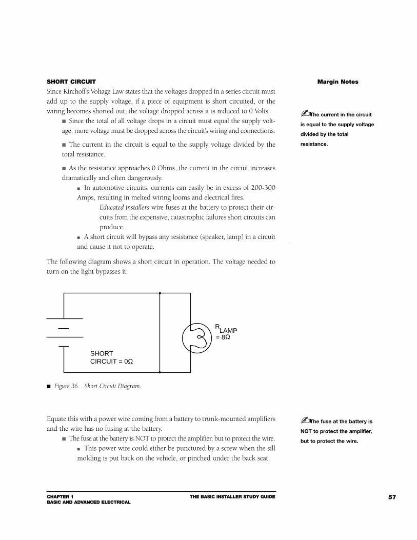
CHAPTER 1BASIC AND ADVANCED ELECTRICAL
THE BASIC INSTALLER STUDY GUIDE 57
SHORT CIRCUIT
Since Kirchoff’s Voltage Law states that the voltages dropped in a series circuit mustadd up to the supply voltage, if a piece of equipment is short circuited, or thewiring becomes shorted out, the voltage dropped across it is reduced to 0 Volts.
Since the total of all voltage drops in a circuit must equal the supply volt-age, more voltage must be dropped across the circuit’s wiring and connections.
The current in the circuit is equal to the supply voltage divided by thetotal resistance.
As the resistance approaches 0 Ohms, the current in the circuit increasesdramatically and often dangerously.
In automotive circuits, currents can easily be in excess of 200-300Amps, resulting in melted wiring looms and electrical fires.
Educated installers wire fuses at the battery to protect their cir-cuits from the expensive, catastrophic failures short circuits canproduce.
A short circuit will bypass any resistance (speaker, lamp) in a circuitand cause it not to operate.
The following diagram shows a short circuit in operation. The voltage needed toturn on the light bypasses it:
Equate this with a power wire coming from a battery to trunk-mounted amplifiersand the wire has no fusing at the battery.
The fuse at the battery is NOT to protect the amplifier, but to protect the wire. This power wire could either be punctured by a screw when the sillmolding is put back on the vehicle, or pinched under the back seat.
Margin Notes
The current in the circuit
is equal to the supply voltage
divided by the total
resistance.
SHORTCIRCUIT = 0Ω
LAMP= 8
R
Ω
Figure 36. Short Circuit Diagram.
The fuse at the battery is
NOT to protect the amplifier,
but to protect the wire.
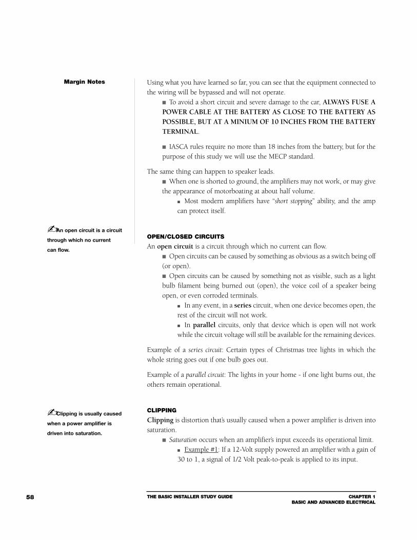
THE BASIC INSTALLER STUDY GUIDE CHAPTER 1BASIC AND ADVANCED ELECTRICAL
58
Using what you have learned so far, you can see that the equipment connected tothe wiring will be bypassed and will not operate.
To avoid a short circuit and severe damage to the car, ALWAYS FUSE APOWER CABLE AT THE BATTERY AS CLOSE TO THE BATTERY ASPOSSIBLE, BUT AT A MINIUM OF 10 INCHES FROM THE BATTERYTERMINAL.
IASCA rules require no more than 18 inches from the battery, but for thepurpose of this study we will use the MECP standard.
The same thing can happen to speaker leads. When one is shorted to ground, the amplifiers may not work, or may givethe appearance of motorboating at about half volume.
Most modern amplifiers have “short stopping” ability, and the ampcan protect itself.
OPEN/CLOSED CIRCUITS
An open circuit is a circuit through which no current can flow. Open circuits can be caused by something as obvious as a switch being off(or open). Open circuits can be caused by something not as visible, such as a lightbulb filament being burned out (open), the voice coil of a speaker beingopen, or even corroded terminals.
In any event, in a series circuit, when one device becomes open, therest of the circuit will not work. In parallel circuits, only that device which is open will not workwhile the circuit voltage will still be available for the remaining devices.
Example of a series circuit: Certain types of Christmas tree lights in which thewhole string goes out if one bulb goes out.
Example of a parallel circuit: The lights in your home - if one light burns out, theothers remain operational.
CLIPPING
Clipping is distortion that’s usually caused when a power amplifier is driven intosaturation.
Saturation occurs when an amplifier’s input exceeds its operational limit. Example #1: If a 12-Volt supply powered an amplifier with a gain of30 to 1, a signal of 1/2 Volt peak-to-peak is applied to its input.
Margin Notes
An open circuit is a circuit
through which no current
can flow.
Clipping is usually caused
when a power amplifier is
driven into saturation.
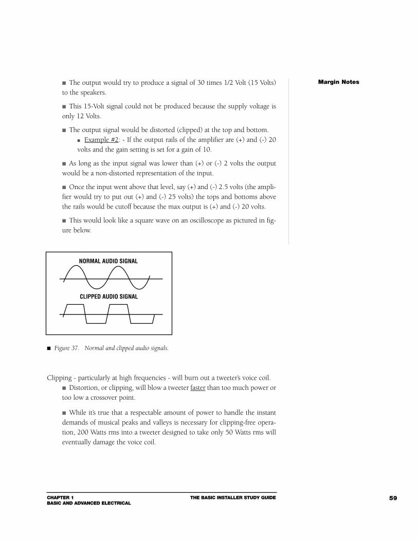
CHAPTER 1BASIC AND ADVANCED ELECTRICAL
THE BASIC INSTALLER STUDY GUIDE 59
The output would try to produce a signal of 30 times 1/2 Volt (15 Volts)to the speakers.
This 15-Volt signal could not be produced because the supply voltage isonly 12 Volts.
The output signal would be distorted (clipped) at the top and bottom. Example #2: - If the output rails of the amplifier are (+) and (-) 20volts and the gain setting is set for a gain of 10.
As long as the input signal was lower than (+) or (-) 2 volts the outputwould be a non-distorted representation of the input.
Once the input went above that level, say (+) and (-) 2.5 volts (the ampli-fier would try to put out (+) and (-) 25 volts) the tops and bottoms abovethe rails would be cutoff because the max output is (+) and (-) 20 volts.
This would look like a square wave on an oscilloscope as pictured in fig-ure below.
Clipping - particularly at high frequencies - will burn out a tweeter’s voice coil. Distortion, or clipping, will blow a tweeter faster than too much power ortoo low a crossover point.
While it’s true that a respectable amount of power to handle the instantdemands of musical peaks and valleys is necessary for clipping-free opera-tion, 200 Watts rms into a tweeter designed to take only 50 Watts rms willeventually damage the voice coil.
Margin Notes
NORMAL AUDIO SIGNAL
CLIPPED AUDIO SIGNAL
Figure 37. Normal and clipped audio signals.
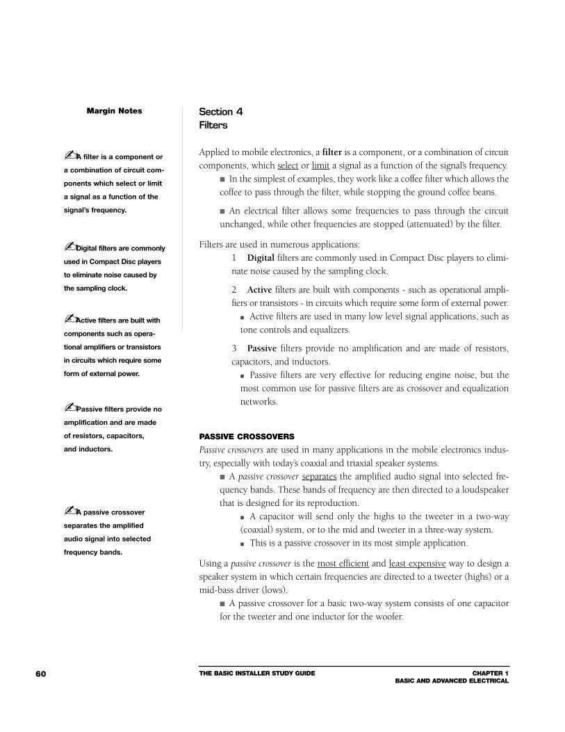
THE BASIC INSTALLER STUDY GUIDE CHAPTER 1BASIC AND ADVANCED ELECTRICAL
60
Section 4Filters
Applied to mobile electronics, a filter is a component, or a combination of circuitcomponents, which select or limit a signal as a function of the signal’s frequency.
In the simplest of examples, they work like a coffee filter which allows thecoffee to pass through the filter, while stopping the ground coffee beans.
An electrical filter allows some frequencies to pass through the circuitunchanged, while other frequencies are stopped (attenuated) by the filter.
Filters are used in numerous applications:1 Digital filters are commonly used in Compact Disc players to elimi-nate noise caused by the sampling clock.
2 Active filters are built with components - such as operational ampli-fiers or transistors - in circuits which require some form of external power.
Active filters are used in many low level signal applications, such astone controls and equalizers.
3 Passive filters provide no amplification and are made of resistors,capacitors, and inductors.
Passive filters are very effective for reducing engine noise, but themost common use for passive filters are as crossover and equalizationnetworks.
PASSIVE CROSSOVERS
Passive crossovers are used in many applications in the mobile electronics indus-try, especially with today’s coaxial and triaxial speaker systems.
A passive crossover separates the amplified audio signal into selected fre-quency bands. These bands of frequency are then directed to a loudspeakerthat is designed for its reproduction.
A capacitor will send only the highs to the tweeter in a two-way(coaxial) system, or to the mid and tweeter in a three-way system. This is a passive crossover in its most simple application.
Using a passive crossover is the most efficient and least expensive way to design aspeaker system in which certain frequencies are directed to a tweeter (highs) or amid-bass driver (lows).
A passive crossover for a basic two-way system consists of one capacitorfor the tweeter and one inductor for the woofer.
Margin Notes
A filter is a component or
a combination of circuit com-
ponents which select or limit
a signal as a function of the
signal’s frequency.
Digital filters are commonly
used in Compact Disc players
to eliminate noise caused by
the sampling clock.
Active filters are built with
components such as opera-
tional amplifiers or transistors
in circuits which require some
form of external power.
Passive filters provide no
amplification and are made
of resistors, capacitors,
and inductors.
A passive crossover
separates the amplified
audio signal into selected
frequency bands.
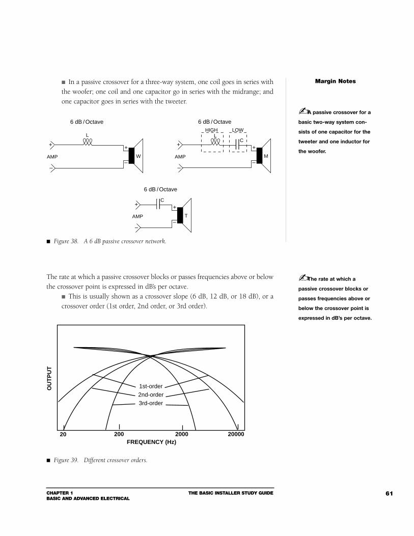
CHAPTER 1BASIC AND ADVANCED ELECTRICAL
THE BASIC INSTALLER STUDY GUIDE 61
In a passive crossover for a three-way system, one coil goes in series withthe woofer; one coil and one capacitor go in series with the midrange; andone capacitor goes in series with the tweeter.
The rate at which a passive crossover blocks or passes frequencies above or belowthe crossover point is expressed in dB’s per octave.
This is usually shown as a crossover slope (6 dB, 12 dB, or 18 dB), or acrossover order (1st order, 2nd order, or 3rd order).
Margin Notes
A passive crossover for a
basic two-way system con-
sists of one capacitor for the
tweeter and one inductor for
the woofer.
L
6 dB / Octave
W
+
–
+
–
AMP
L
6 dB / Octave
M
+
–
+
–
AMP
HIGH LOW
C
6 dB / Octave
T
+
–
+
–
AMP
C
Figure 38. A 6 dB passive crossover network.
The rate at which a
passive crossover blocks or
passes frequencies above or
below the crossover point is
expressed in dB’s per octave.
FREQUENCY (Hz)
OU
TP
UT
20 200 2000 20000
1st-order2nd-order3rd-order
Figure 39. Different crossover orders.
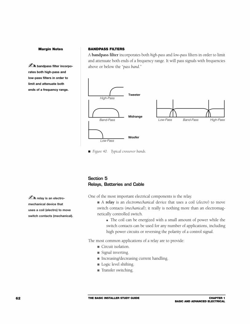
THE BASIC INSTALLER STUDY GUIDE CHAPTER 1BASIC AND ADVANCED ELECTRICAL
62
BANDPASS FILTERS
A bandpass filter incorporates both high-pass and low-pass filters in order to limitand attenuate both ends of a frequency range. It will pass signals with frequenciesabove or below the “pass band.”
Section 5Relays, Batteries and Cable
One of the most important electrical components is the relay. A relay is an electromechanical device that uses a coil (electro) to moveswitch contacts (mechanical); it really is nothing more than an electromag-netically controlled switch.
The coil can be energized with a small amount of power while theswitch contacts can be used for any number of applications, includinghigh power circuits or reversing the polarity of a control signal.
The most common applications of a relay are to provide: Circuit isolation. Signal inverting. Increasing/decreasing current handling. Logic level shifting. Transfer switching.
Margin Notes
A bandpass filter incorpo-
rates both high-pass and
low-pass filters in order to
limit and attenuate both
ends of a frequency range.
High-Pass
Low-PassBand-Pass Band-Pass
Low-Pass
High-Pass
Tweeter
Midrange
Woofer
Figure 40. Typical crossover bands.
A relay is an electro-
mechanical device that
uses a coil (electro) to move
switch contacts (mechanical).
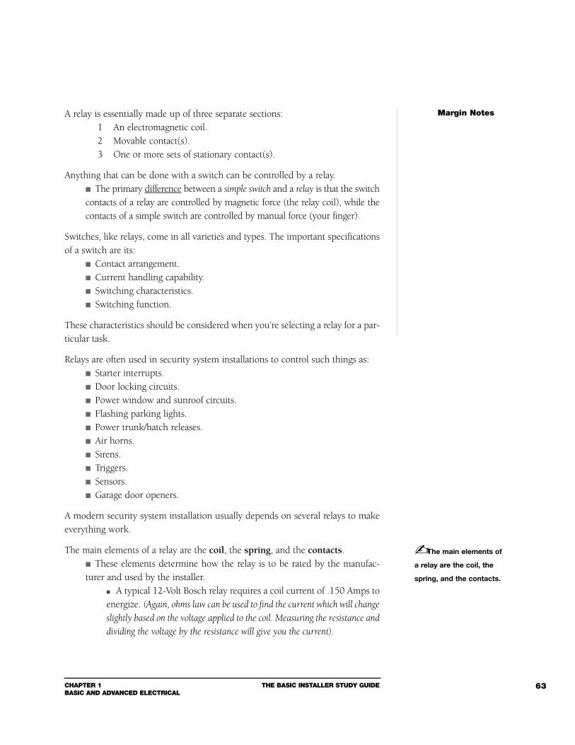
CHAPTER 1BASIC AND ADVANCED ELECTRICAL
THE BASIC INSTALLER STUDY GUIDE 63
A relay is essentially made up of three separate sections:1 An electromagnetic coil.2 Movable contact(s).3 One or more sets of stationary contact(s).
Anything that can be done with a switch can be controlled by a relay. The primary difference between a simple switch and a relay is that the switchcontacts of a relay are controlled by magnetic force (the relay coil), while thecontacts of a simple switch are controlled by manual force (your finger).
Switches, like relays, come in all varieties and types. The important specificationsof a switch are its:
Contact arrangement. Current handling capability. Switching characteristics. Switching function.
These characteristics should be considered when you’re selecting a relay for a par-ticular task.
Relays are often used in security system installations to control such things as: Starter interrupts. Door locking circuits. Power window and sunroof circuits. Flashing parking lights. Power trunk/hatch releases. Air horns. Sirens. Triggers. Sensors. Garage door openers.
A modern security system installation usually depends on several relays to makeeverything work.
The main elements of a relay are the coil, the spring, and the contacts. These elements determine how the relay is to be rated by the manufac-turer and used by the installer.
A typical 12-Volt Bosch relay requires a coil current of .150 Amps toenergize. (Again, ohms law can be used to find the current which will change
slightly based on the voltage applied to the coil. Measuring the resistance and
dividing the voltage by the resistance will give you the current).
Margin Notes
The main elements of
a relay are the coil, the
spring, and the contacts.
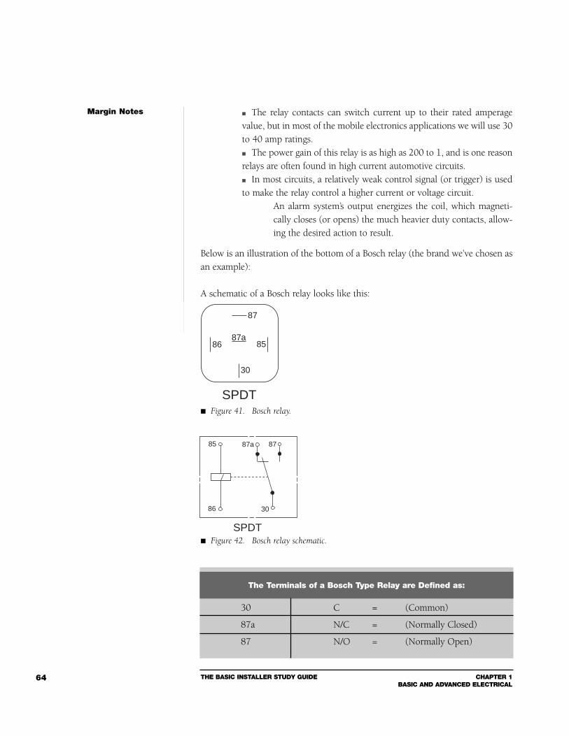
THE BASIC INSTALLER STUDY GUIDE CHAPTER 1BASIC AND ADVANCED ELECTRICAL
64
The relay contacts can switch current up to their rated amperagevalue, but in most of the mobile electronics applications we will use 30to 40 amp ratings. The power gain of this relay is as high as 200 to 1, and is one reasonrelays are often found in high current automotive circuits. In most circuits, a relatively weak control signal (or trigger) is usedto make the relay control a higher current or voltage circuit.
An alarm system’s output energizes the coil, which magneti-cally closes (or opens) the much heavier duty contacts, allow-ing the desired action to result.
Below is an illustration of the bottom of a Bosch relay (the brand we’ve chosen asan example):
A schematic of a Bosch relay looks like this:
Margin Notes
87
858687a
30
SPDT Figure 41. Bosch relay.
8785
86
87a
30
SPDT Figure 42. Bosch relay schematic.
30 C = (Common)
87a N/C = (Normally Closed)
87 N/O = (Normally Open)
The Terminals of a Bosch Type Relay are Defined as:
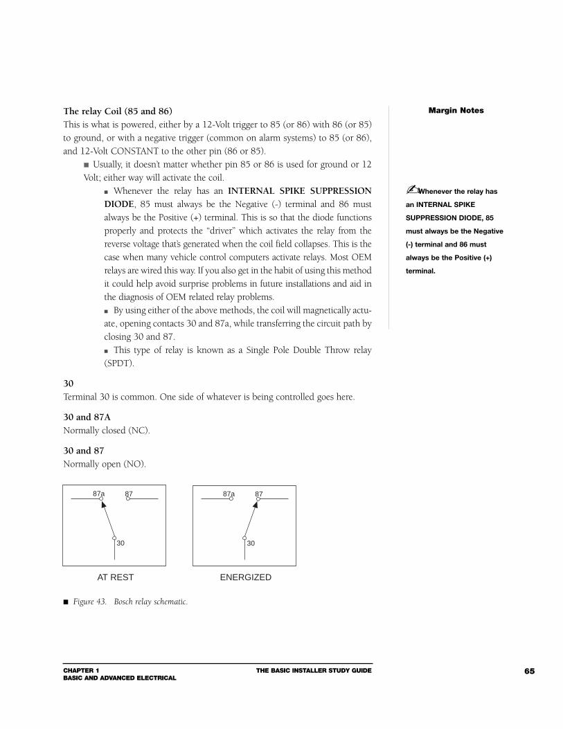
CHAPTER 1BASIC AND ADVANCED ELECTRICAL
THE BASIC INSTALLER STUDY GUIDE 65
The relay Coil (85 and 86)This is what is powered, either by a 12-Volt trigger to 85 (or 86) with 86 (or 85)to ground, or with a negative trigger (common on alarm systems) to 85 (or 86),and 12-Volt CONSTANT to the other pin (86 or 85).
Usually, it doesn’t matter whether pin 85 or 86 is used for ground or 12Volt; either way will activate the coil.
Whenever the relay has an INTERNAL SPIKE SUPPRESSIONDIODE, 85 must always be the Negative (-) terminal and 86 mustalways be the Positive (+) terminal. This is so that the diode functionsproperly and protects the “driver” which activates the relay from thereverse voltage that’s generated when the coil field collapses. This is thecase when many vehicle control computers activate relays. Most OEMrelays are wired this way. If you also get in the habit of using this methodit could help avoid surprise problems in future installations and aid inthe diagnosis of OEM related relay problems. By using either of the above methods, the coil will magnetically actu-ate, opening contacts 30 and 87a, while transferring the circuit path byclosing 30 and 87. This type of relay is known as a Single Pole Double Throw relay(SPDT).
30Terminal 30 is common. One side of whatever is being controlled goes here.
30 and 87ANormally closed (NC).
30 and 87Normally open (NO).
Margin Notes
Whenever the relay has
an INTERNAL SPIKE
SUPPRESSION DIODE, 85
must always be the Negative
(-) terminal and 86 must
always be the Positive (+)
terminal.
Figure 43. Bosch relay schematic.
8787a
30
8787a
30
AT REST ENERGIZED
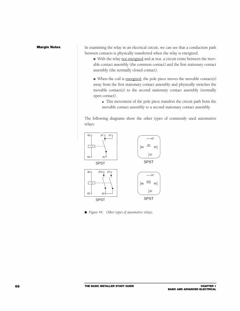
THE BASIC INSTALLER STUDY GUIDE CHAPTER 1BASIC AND ADVANCED ELECTRICAL
66
In examining the relay in an electrical circuit, we can see that a conduction pathbetween contacts is physically transferred when the relay is energized.
With the relay not energized and at rest, a circuit exists between the mov-able contact assembly (the common contact) and the first stationary contactassembly (the normally closed contact).
When the coil is energized, the pole piece moves the movable contact(s)away from the first stationary contact assembly and physically switches themovable contact(s) to the second stationary contact assembly (normallyopen contact).
This movement of the pole piece transfers the circuit path from themovable contact assembly to a second stationary contact assembly.
The following diagrams show the other types of commonly used automotiverelays:
Margin Notes
Figure 44. Other types of automotive relays.
87
858687
30
SPST
87
858687b
30
SPST
8786
85
87b
30
SPST
85
86
SPST
30
8787
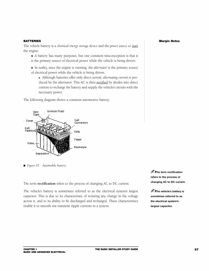
CHAPTER 1BASIC AND ADVANCED ELECTRICAL
THE BASIC INSTALLER STUDY GUIDE 67
BATTERIES
The vehicle battery is a chemical energy storage device and the power source to startthe engine.
A battery has many purposes, but one common misconception is that itis the primary source of electrical power while the vehicle is being driven.
In reality, once the engine is running, the alternator is the primary sourceof electrical power while the vehicle is being driven.
Although batteries offer only direct current, alternating current is pro-duced by the alternator. This AC is then rectified by diodes into directcurrent to recharge the battery and supply the vehicle’s circuits with thenecessary power.
The following diagram shows a common automotive battery:
The term rectification refers to the process of changing AC to DC current.
The vehicle’s battery is sometimes referred to as the electrical system’s largestcapacitor. This is due to its characteristic of resisting any change in the voltageacross it, and to its ability to be discharged and recharged. These characteristicsenable it to smooth out transient ripple currents in a system.
Margin Notes
The term rectification
refers to the process of
changing AC to DC current.
Figure 45. Automobile battery.
The vehicle’s battery is
sometimes referred to as
the electrical system’s
largest capacitor.
THE BASIC INSTALLER STUDY GUIDE CHAPTER 1BASIC AND ADVANCED ELECTRICAL
68
A car lead-acid type battery is made up of six cells. In a fully charged 12-Volt battery with no load on it (open circuit), eachcell has a nominal voltage output of 2.11 Volts. The battery fluid is called electrolyte, which is sulfuric acid and water.
When a circuit is powered by the battery, a chemical reaction takesplace inside the cells between its electrolyte and lead plates, and a cur-rent flow is established. When the battery is recharging, the chemical reaction not only stops,but is reversed, allowing the electrical charging energy to be chemical-ly stored within the cells for later use. The output power of a battery is determined by its energy storagecapacity (cold-cranking amps), and the ability of the battery to smoothripple currents is a function of both its internal resistance and capacity. As a battery ages, its ability to filter ripple current (noise) decreases,and its impedance increases. (See battery cutaway in back of book.) Remember that the battery is an electro-chemical device and cannotcreate current instantaneously, so as current is drawn voltage willdecrease.
Running a “new” standard car battery until it’s dead may result in the battery’sreserve capacity being reduced by half.
Once an automotive lead-acid battery has been “deep-cycled,” it cannotbe recharged to its original specifications. Dropping the battery’s rated volt-age by 25% is what is meant by deep-cycled.
A “primary” battery can store and deliver electrical energy, but cannot berecharged.
Lead-acid automobile batteries are “secondary” batteries. A secondary battery can also store and deliver electrical energy, but unlikethe primary battery, recharging is possible by passing a direct currentthrough the battery in the opposite direction to that of the discharge.
CABLE QUALITY
Expert mechanical installation will be of limited value if you don’t use high-qual-ity cable of the correct size for the electrical installation. Remember the water pipeanalogy in Section 1? This is a good way to think of signal (or current) flowthrough speakers and power cables.
When a large amount of water has to go through a pipe which is too small,it will take longer for the water to go through the pipe, and the full flow ofwater is reduced.
Margin Notes
A “primary” battery can
store and deliver electrical
energy, but cannot be
recharged.
CHAPTER 1BASIC AND ADVANCED ELECTRICAL
THE BASIC INSTALLER STUDY GUIDE 69
When a larger, proper sized pipe replaces the small pipe, the same volumeof water flows freely, with less resistance.
Applying this example to electricity: The pipe is the power cable, which experiences increased voltage drops ifit’s too small to carry the required current.
The water represents the current flowing. If the wire is too small or too long, resistance is increased. As resistance increases, the power cable will start to overheat. Theheat could melt the cable and create a hazard to the system and thevehicle. Also, as resistance increases, the power amplifier at the other end ofthis small, overworked cable suffers a significant voltage drop. This willnot allow the amplifier to get the full voltage and the current it needsto operate properly, which will diminish its output and could easilycause distortion.
Always remember to use the proper size (even slightly oversized) power, ground,and speaker cables.
For power amplifier wiring, you will need sufficient AWG rating to handle thecurrent load (see IASCA chart in Section 1).
You will also need a high temperature, multi-strand cable. A flexible gas and oilresistant outer jacket is also desirable. Never use solid wire in the high vibrationenvironment a vehicle creates.
A common misconception is that you can skimp on the ground cable. The ground cable carries as much current back to its source (the battery) asthe supply cable, and should really have a gauge the same current potential ofthe supply cable. Using the same size gauge wire (since the ground/chassisconnection is generally shorter) is a good practice to use.
Knowing what voltage will be present at the amplifier end of the supply cable (i.e.,battery voltage less voltage drop) is also important when selecting a proper gaugepower cable.
If you know the maximum amperage the system is going to draw and theresistance per foot of cable, the voltage drop is easy to calculate.
Use what you know about Ohm’s Law to figure out the following formula:
E = I x R
Margin Notes
As resistance increases,
the power cable will start to
overheat. The heat could melt
the cable and create a hazard
to the system and the vehicle.
You will also need a high
temperature, multi-strand
cable. A flexible, gas and oil
resistant outer jacket is also
desirable. Never use solid
wire in the high vibration
environment a vehicle creates.
THE BASIC INSTALLER STUDY GUIDE CHAPTER 1BASIC AND ADVANCED ELECTRICAL
70
If you are installing a system which has a 13-Amp draw and usinga AWG size #10 cable (assume that #10 cable has a resistance of .047 Ohms for a20 ft. run), how would you find the voltage drop at the amplifier end of the cable?
E = I x R(voltage) (amperage) (resistance)
E = 13 (Amps) x .047 (Ohms)
E = .61 Volt loss
Nearly two-thirds of a volt is lost between the battery and the amplifier. Think ofhow this could affect peak amplifier performance!
When selecting speaker cables, shielded audio cables, and power cables, selectones using deoxygenated, also known as oxygen-free, copper cable.
Deoxygenated copper has had nearly all the oxygen removed from thecopper during the manufacturing process. The result is less resistance (thespeaker, amplifier input, and the amplifier itself get more power), and thewiring will not corrode and turn green as normal copper cable will over timeor if the vehicle is in a damp or salty environment.
There are four factors that determine the resistance of a cable:1 The cross sectional area (i.e., the AWG size; the larger the cross-sec-tion, the lower the resistance).2 The temperature of the conductor (higher temperature means higherresistance).3 The “resistivity” of the material the cable is made of (copper, deoxy-genated copper, aluminum).4 The length of the conductor (more wire length equals more resistance).
Although you cannot control the temperature of a cable, you can do a lot to con-trol the other remaining factors.
Margin Notes
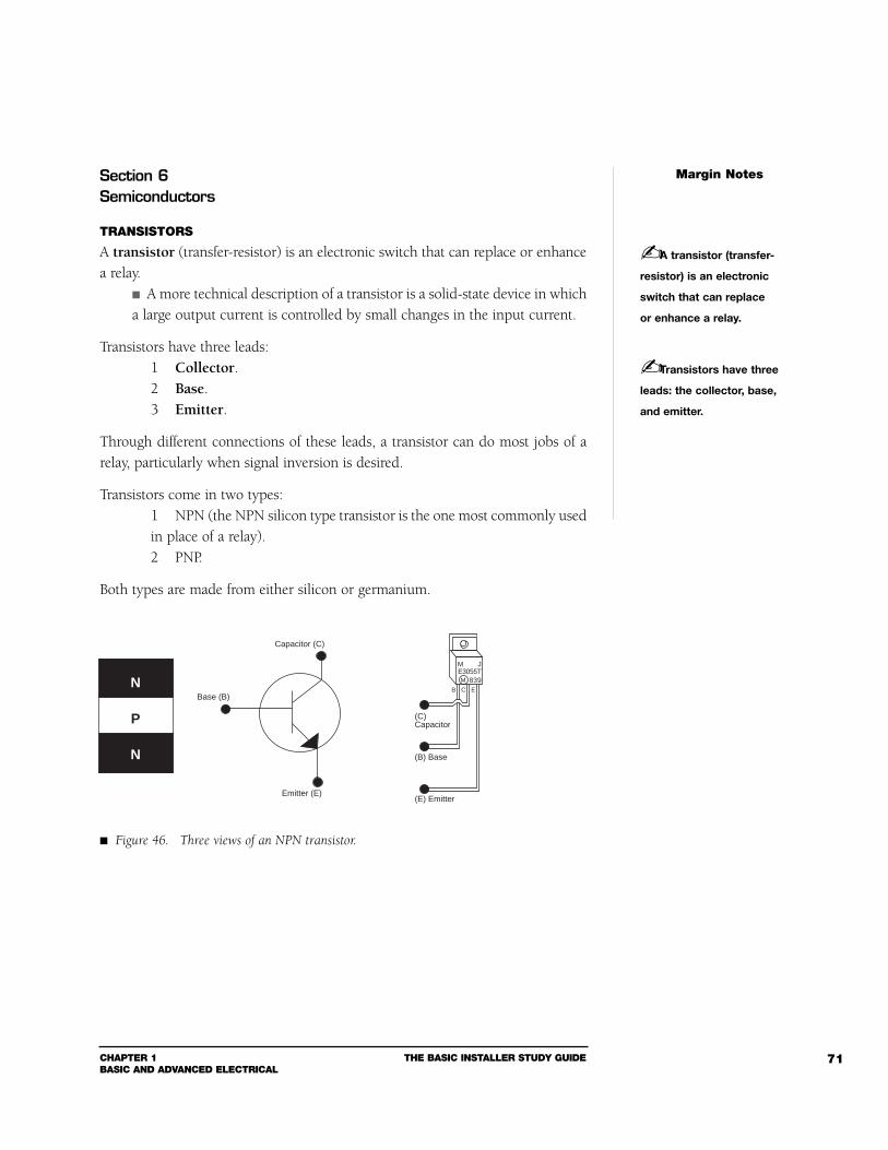
CHAPTER 1BASIC AND ADVANCED ELECTRICAL
THE BASIC INSTALLER STUDY GUIDE 71
Section 6Semiconductors
TRANSISTORS
A transistor (transfer-resistor) is an electronic switch that can replace or enhancea relay.
A more technical description of a transistor is a solid-state device in whicha large output current is controlled by small changes in the input current.
Transistors have three leads:1 Collector.2 Base.3 Emitter.
Through different connections of these leads, a transistor can do most jobs of arelay, particularly when signal inversion is desired.
Transistors come in two types:1 NPN (the NPN silicon type transistor is the one most commonly usedin place of a relay).2 PNP.
Both types are made from either silicon or germanium.
Margin Notes
A transistor (transfer-
resistor) is an electronic
switch that can replace
or enhance a relay.
Transistors have three
leads: the collector, base,
and emitter.
N
P
N
Capacitor (C)
Base (B)
Emitter (E)
(C)Capacitor
(E) Emitter
(B) Base
M JE3055T
839M
B C E
Figure 46. Three views of an NPN transistor.
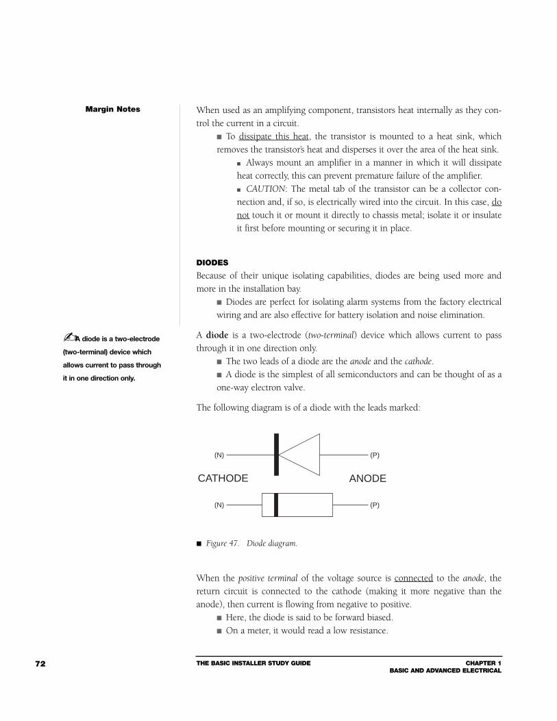
THE BASIC INSTALLER STUDY GUIDE CHAPTER 1BASIC AND ADVANCED ELECTRICAL
72
When used as an amplifying component, transistors heat internally as they con-trol the current in a circuit.
To dissipate this heat, the transistor is mounted to a heat sink, whichremoves the transistor’s heat and disperses it over the area of the heat sink.
Always mount an amplifier in a manner in which it will dissipateheat correctly, this can prevent premature failure of the amplifier. CAUTION: The metal tab of the transistor can be a collector con-nection and, if so, is electrically wired into the circuit. In this case, donot touch it or mount it directly to chassis metal; isolate it or insulateit first before mounting or securing it in place.
DIODES
Because of their unique isolating capabilities, diodes are being used more andmore in the installation bay.
Diodes are perfect for isolating alarm systems from the factory electricalwiring and are also effective for battery isolation and noise elimination.
A diode is a two-electrode (two-terminal) device which allows current to passthrough it in one direction only.
The two leads of a diode are the anode and the cathode. A diode is the simplest of all semiconductors and can be thought of as aone-way electron valve.
The following diagram is of a diode with the leads marked:
When the positive terminal of the voltage source is connected to the anode, thereturn circuit is connected to the cathode (making it more negative than theanode), then current is flowing from negative to positive.
Here, the diode is said to be forward biased. On a meter, it would read a low resistance.
Margin Notes
A diode is a two-electrode
(two-terminal) device which
allows current to pass through
it in one direction only.
(N) (P)
(N) (P)
CATHODE ANODE
Figure 47. Diode diagram.
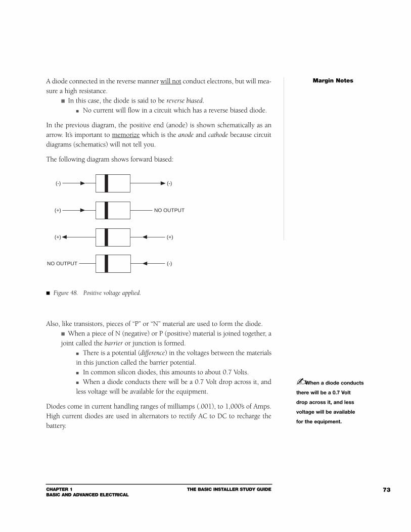
CHAPTER 1BASIC AND ADVANCED ELECTRICAL
THE BASIC INSTALLER STUDY GUIDE 73
A diode connected in the reverse manner will not conduct electrons, but will mea-sure a high resistance.
In this case, the diode is said to be reverse biased. No current will flow in a circuit which has a reverse biased diode.
In the previous diagram, the positive end (anode) is shown schematically as anarrow. It’s important to memorize which is the anode and cathode because circuitdiagrams (schematics) will not tell you.
The following diagram shows forward biased:
Also, like transistors, pieces of “P” or “N” material are used to form the diode. When a piece of N (negative) or P (positive) material is joined together, ajoint called the barrier or junction is formed.
There is a potential (difference) in the voltages between the materialsin this junction called the barrier potential. In common silicon diodes, this amounts to about 0.7 Volts. When a diode conducts there will be a 0.7 Volt drop across it, andless voltage will be available for the equipment.
Diodes come in current handling ranges of milliamps (.001), to 1,000’s of Amps.High current diodes are used in alternators to rectify AC to DC to recharge thebattery.
Margin Notes
(+) NO OUTPUT
(-) (-)
(+) (+)
(-)NO OUTPUT
Figure 48. Positive voltage applied.
When a diode conducts
there will be a 0.7 Volt
drop across it, and less
voltage will be available
for the equipment.
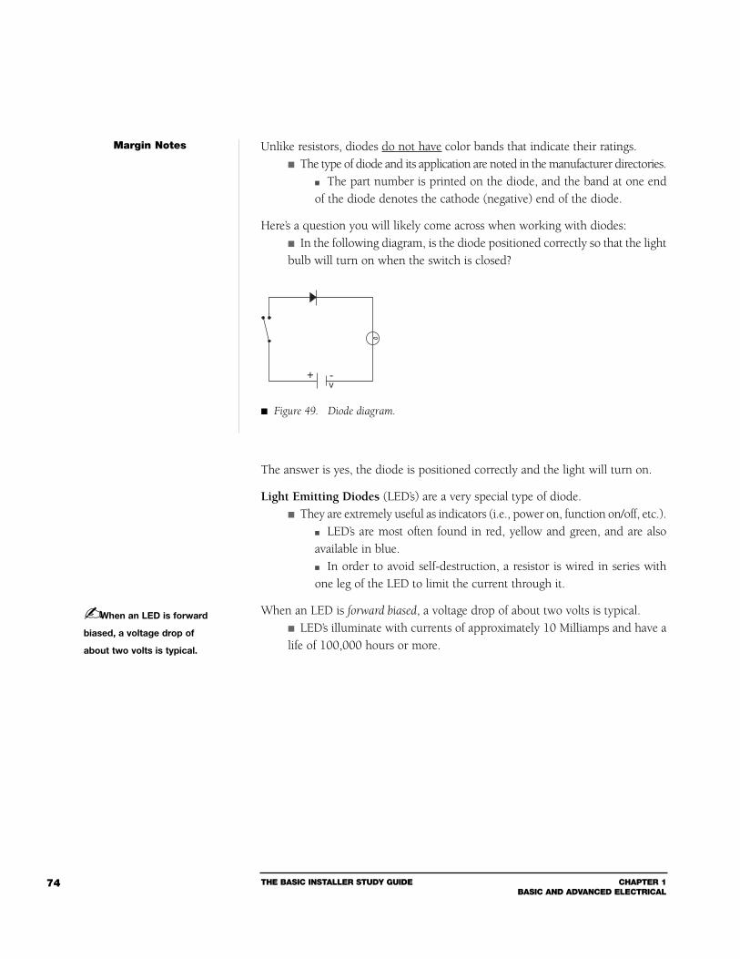
THE BASIC INSTALLER STUDY GUIDE CHAPTER 1BASIC AND ADVANCED ELECTRICAL
74
Unlike resistors, diodes do not have color bands that indicate their ratings. The type of diode and its application are noted in the manufacturer directories.
The part number is printed on the diode, and the band at one endof the diode denotes the cathode (negative) end of the diode.
Here’s a question you will likely come across when working with diodes: In the following diagram, is the diode positioned correctly so that the lightbulb will turn on when the switch is closed?
The answer is yes, the diode is positioned correctly and the light will turn on.
Light Emitting Diodes (LED’s) are a very special type of diode. They are extremely useful as indicators (i.e., power on, function on/off, etc.).
LED’s are most often found in red, yellow and green, and are alsoavailable in blue. In order to avoid self-destruction, a resistor is wired in series withone leg of the LED to limit the current through it.
When an LED is forward biased, a voltage drop of about two volts is typical. LED’s illuminate with currents of approximately 10 Milliamps and have alife of 100,000 hours or more.
Margin Notes
When an LED is forward
biased, a voltage drop of
about two volts is typical.
+ -v
Figure 49. Diode diagram.
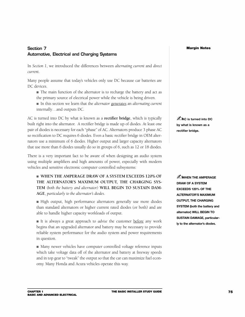
CHAPTER 1BASIC AND ADVANCED ELECTRICAL
THE BASIC INSTALLER STUDY GUIDE 75
Section 7Automotive, Electrical and Charging Systems
In Section 1, we introduced the differences between alternating current and direct
current.
Many people assume that today’s vehicles only use DC because car batteries areDC devices.
The main function of the alternator is to recharge the battery and act asthe primary source of electrical power while the vehicle is being driven. In this section we learn that the alternator generates an alternating current
internally…and outputs DC.
AC is turned into DC by what is known as a rectifier bridge, which is typicallybuilt right into the alternator. A rectifier bridge is made up of diodes. At least onepair of diodes is necessary for each “phase” of AC. Alternators produce 3 phase ACso rectification to DC requires 6 diodes. Even a basic rectifier bridge in OEM alter-nators use a minimum of 6 diodes. Higher output and larger capacity alternatorsthat use more than 6 diodes usually do so in groups of 6, such as 12 or 18 diodes.
There is a very important fact to be aware of when designing an audio systemusing multiple amplifiers and high amounts of power, especially with modernvehicles and sensitive electronic computer controlled subsystems:
WHEN THE AMPERAGE DRAW OF A SYSTEM EXCEEDS 120% OFTHE ALTERNATOR’S MAXIMUM OUTPUT, THE CHARGING SYS-TEM (both the battery and alternator) WILL BEGIN TO SUSTAIN DAM-AGE, particularly to the alternator’s diodes.
High output, high performance alternators generally use more diodesthan standard alternators or higher current rated diodes (or both) and areable to handle higher capacity workloads of output.
It is always a great approach to advise the customer before any workbegins that an upgraded alternator and battery may be necessary to providereliable system performance for the audio system and power requirementsin question.
Many newer vehicles have computer controlled voltage reference inputswhich take voltage data off of the alternator and battery at freeway speedsand in top gear to “tweak” the output so that the car can maximize fuel econ-omy. Many Honda and Acura vehicles operate this way.
Margin Notes
AC is turned into DC
by what is known as a
rectifier bridge.
WHEN THE AMPERAGE
DRAW OF A SYSTEM
EXCEEDS 120% OF THE
ALTERNATOR’S MAXIMUM
OUTPUT, THE CHARGING
SYSTEM (both the battery and
alternator) WILL BEGIN TO
SUSTAIN DAMAGE, particular-
ly to the alternator’s diodes.
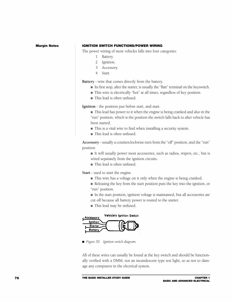
THE BASIC INSTALLER STUDY GUIDE CHAPTER 1BASIC AND ADVANCED ELECTRICAL
76
IGNITION SWITCH FUNCTIONS/POWER WIRING
The power wiring of most vehicles falls into four categories:1 Battery.2 Ignition.3 Accessory.4 Start.
Battery - wire that comes directly from the battery. Its first stop, after the starter, is usually the “Batt” terminal on the keyswitch. This wire is electrically “hot” at all times, regardless of key position. This lead is often unfused.
Ignition - the position just before start, and start. This lead has power to it when the engine is being cranked and also in the“run” position, which is the position the switch falls back to after vehicle hasbeen started. This is a vital wire to find when installing a security system. This lead is often unfused.
Accessory - usually a counterclockwise turn from the “off” position, and the “run”position.
It will usually power most accessories, such as radios, wipers, etc., but iswired separately from the ignition circuits. This lead is often unfused.
Start - used to start the engine. This wire has a voltage on it only when the engine is being cranked. Releasing the key from the start position puts the key into the ignition, or“run” position. In the start position, ignition voltage is maintained, but all accessories arecut off because all battery power is routed to the starter. This lead may be unfused.
All of these wires can usually be found at the key switch and should be function-ally verified with a DMM, not an incandescent type test light, so as not to dam-age any computers in the electrical system.
Margin Notes
Figure 50. Ignition switch diagram.
CHAPTER 1BASIC AND ADVANCED ELECTRICAL
THE BASIC INSTALLER STUDY GUIDE 77
Section 8Troubleshooting Guide
OVERALL
If there is no power in the entire system: Check the main fuse at the battery. To avoid a short circuit and severe damage to the vehicle - always fuse a power
cable at the battery within six inches of the battery.
If there is no power to the amplifier or amplifiers, but other components have power: Check the fuses for the amplifiers first. Then, check the main fuse.
If there is no power to the headunit, but other components have power: Check the factory fuses (at the OEM fuse panel) labled RADIO first. Then, check the main fuse at the headunit in the dash.
If an amplifier overheats, “motorboats” or fails: Use Ohm’s Law ( E = I x R ) to determine if:
The gauge wire is too small. The vehicle requires a higher output alternator. The ground wire gauge is too small.
Use a DMM or a VOM to determine if: A speaker may be “shorted out”. The voltage to the amplifier is too low. A fuse has blown.
If a resistor fails: Use a Volt Ohm Meter (VOM) to measure current and voltage, then useOhm’s Law to calculate resistance. Make sure you’re using the correct resistor (too low a value and it willoverheat and fail).
When resistors are connected in series, the total resistance is the sumof the resistance of each component. When devices are wired in parallel, the total resistance is always lessthan the resistance of the component with the smallest value.
If there is a voltage drop in the system: Is the voltage drop caused by a bad connection? Is the wire gauge too small? Look for the source of added resistance.
Use Kirchoff’s Voltage Law (KVL)to determine the voltage drop. Remember to use effective resistance - the “calculated” resistance thata device presents to a circuit while it is operating.
Margin Notes
THE BASIC INSTALLER STUDY GUIDE CHAPTER 1BASIC AND ADVANCED ELECTRICAL
78
Is there “alternator whine”?: Check for a ground loop.
Poor crimps can cause a ground loop. Check the alternator. Check for audio cables which run near high current power wiring. Check for passive crossovers installed near factory wiring harnesses. Measure the ground point potential back to the negative battery post andwith each other.
Single point grounding is preferred.
If the input signal voltage is too high to an amplifier: Add a voltage divider (resistor network) to the signal cable.
If there are “burn marks” on the areas surrounding a resistor: Make sure the resistor is not overheating. Be sure there is adequate airflow around all resistors.
If the alternator fails: It may be possible that the amperage draw of the system exceeds 120% ofthe alternator’s maximum output. Most OEM charging systems (BOTH bat-tery and alternator) will begin to sustain damage at that level, particularly tothe alternator’s diodes.
If this is the case, advise the customer before any work begins thatan upgraded alternator and battery may be necessary to provide reli-able system performance for the audio system and power requirementsin question.
SPEAKERS
If tweeters are always “blowing”: Install a fuse - wired in series - with the speaker.
To determine the proper amperage of the fuse, you’ll need to knowthe ohm load of the speaker as well as its continuous or nominal powerrating.
Check that the output is not clipping, if it is reduce volume or gain. This is often a symptom of electrical (heat related) tweeter failures.
If speakers are always “blowing”: Check that the output is not clipping, if it is reduce volume or gain.
This is often a symptom of electrical (heat related)speaker failures. Check that the excursion limit of the speaker is not being exceeded athigh volume.
This is often a symptom of mechanical (excursion related)speaker failures.
Margin Notes
CHAPTER 1BASIC AND ADVANCED ELECTRICAL
THE BASIC INSTALLER STUDY GUIDE 79
If sound quality is poor: Check for a bad connection or poorly crimped terminal. Check that the speakers are connected in parallel.
When “paralleled” speakers are connected to the amplifier, the com-bined speaker load will have a significant effect on how that amplifierperforms. It may also cause the amplifier to run excessively hot.
Check to see if the LOUDNESS is switched on, if so switch to OFF. Check to see if the Bass and Treble settings are boosted, if so set to FLAT.
If too much power is reaching a speaker: Add a power resistor to reduce the amount of power. Check that the output is not clipping, if it is reduce volume or gain.
If high frequencies are reaching the subwoofer: Install an inductor - wired in series - to block the higher frequency signalswhile allowing the low frequency audio signal to power the speaker (thiscreates a low-pass passive crossover).
If low frequencies are reaching the tweeters: Install a capacitor - wired in series - to block the lower frequency signalswhile allowing the high frequency audio signal to power the speaker (thiscreates a high-pass passive crossover).
This concludes our discussion of 12-Volt electrical. If you’ve read each section ofthis Chapter thoroughly and followed the instructions stated in the Introduction,then you should be well prepared to answer the electrical section test questionson the MECP Basic Installer exam.
Margin Notes
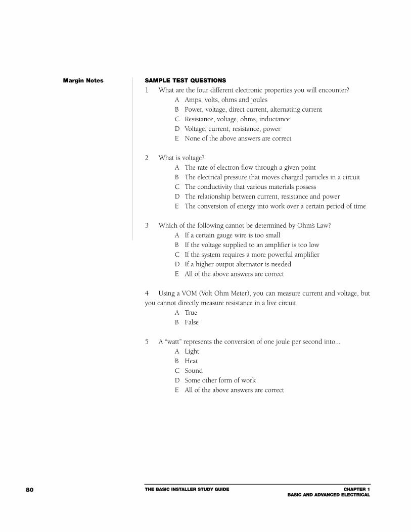
THE BASIC INSTALLER STUDY GUIDE CHAPTER 1BASIC AND ADVANCED ELECTRICAL
80
SAMPLE TEST QUESTIONS
1 What are the four different electronic properties you will encounter?A Amps, volts, ohms and joulesB Power, voltage, direct current, alternating currentC Resistance, voltage, ohms, inductanceD Voltage, current, resistance, powerE None of the above answers are correct
2 What is voltage?A The rate of electron flow through a given pointB The electrical pressure that moves charged particles in a circuitC The conductivity that various materials possessD The relationship between current, resistance and powerE The conversion of energy into work over a certain period of time
3 Which of the following cannot be determined by Ohm’s Law?A If a certain gauge wire is too smallB If the voltage supplied to an amplifier is too lowC If the system requires a more powerful amplifierD If a higher output alternator is neededE All of the above answers are correct
4 Using a VOM (Volt Ohm Meter), you can measure current and voltage, butyou cannot directly measure resistance in a live circuit.
A TrueB False
5 A “watt” represents the conversion of one joule per second into...A LightB HeatC SoundD Some other form of workE All of the above answers are correct
Margin Notes
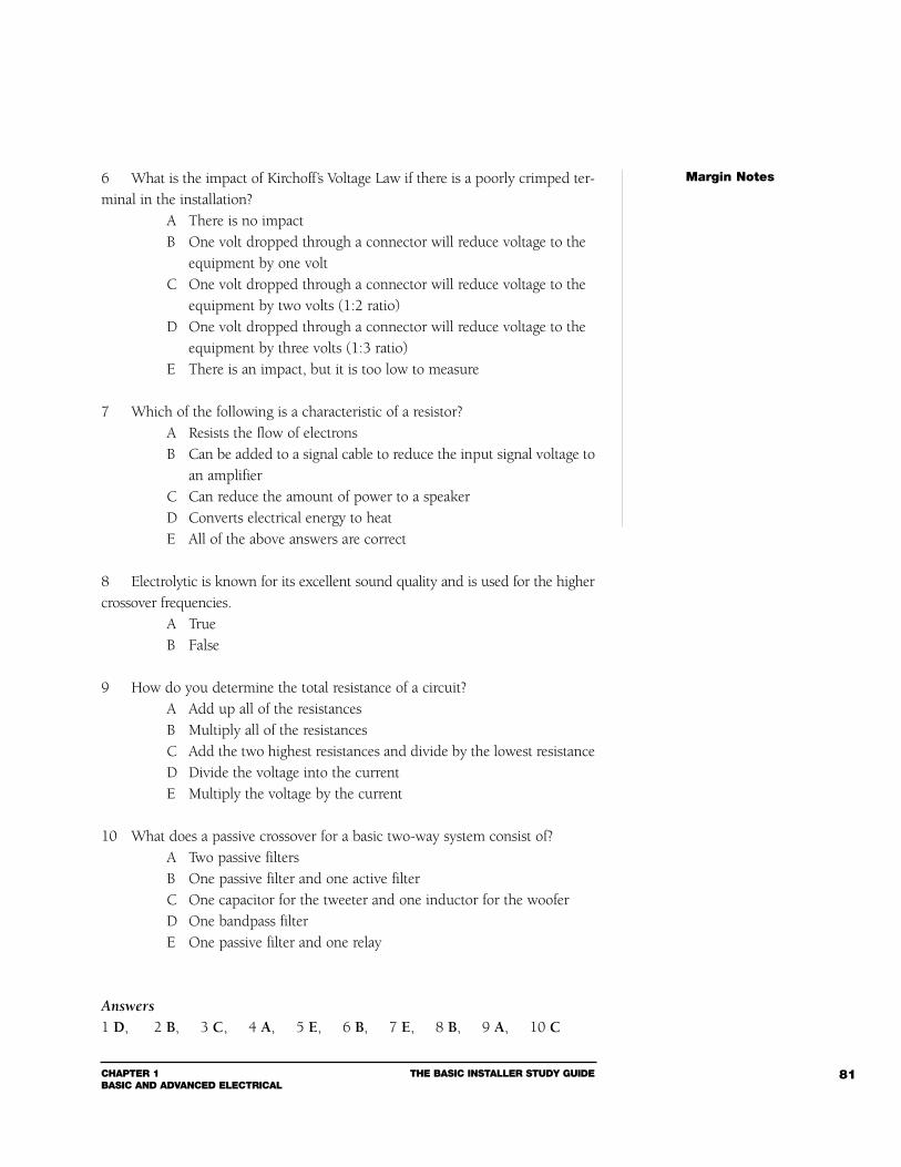
CHAPTER 1BASIC AND ADVANCED ELECTRICAL
THE BASIC INSTALLER STUDY GUIDE 81
6 What is the impact of Kirchoff’s Voltage Law if there is a poorly crimped ter-minal in the installation?
A There is no impactB One volt dropped through a connector will reduce voltage to the
equipment by one voltC One volt dropped through a connector will reduce voltage to the
equipment by two volts (1:2 ratio)D One volt dropped through a connector will reduce voltage to the
equipment by three volts (1:3 ratio)E There is an impact, but it is too low to measure
7 Which of the following is a characteristic of a resistor?A Resists the flow of electronsB Can be added to a signal cable to reduce the input signal voltage to
an amplifierC Can reduce the amount of power to a speakerD Converts electrical energy to heatE All of the above answers are correct
8 Electrolytic is known for its excellent sound quality and is used for the highercrossover frequencies.
A TrueB False
9 How do you determine the total resistance of a circuit?A Add up all of the resistancesB Multiply all of the resistances C Add the two highest resistances and divide by the lowest resistanceD Divide the voltage into the currentE Multiply the voltage by the current
10 What does a passive crossover for a basic two-way system consist of?A Two passive filtersB One passive filter and one active filterC One capacitor for the tweeter and one inductor for the wooferD One bandpass filterE One passive filter and one relay
Answers1 D, 2 B, 3 C, 4 A, 5 E, 6 B, 7 E, 8 B, 9 A, 10 C
Margin Notes

2
CHAPTER 2INSTALLATION KNOWLEDGE & TECHNIQUE
The bottom line: Working as a Professional Installer, you have to be able to
tackle the challenges that you face in your day-to-day duties. While that often
requires a high degree of creativity, it also necessitates a solid foundation in
the basics. This chapter focuses on some basic installation practices, includ-
ing proper tool use and safety. These are best practices that every profes-
sional installer should follow.
Both the Basic Installer level and the First Class level Installation Knowledge
& Technique section of the MECP certification tests are included here. You
should have a thorough understanding of each topic before moving on to the
next topic. For the First Class level test read all of this Chapter as well as the
complete First Class Study Guide available from MECP.
THE BASIC INSTALLER STUDY GUIDE CHAPTER 2INSTALLATION KNOWLEDGE & TECHNIQUE
84
Section 1Basic Installation Practices
A professional installation is not just about the quality of your work – it alsoincludes your preparedness and professionalism. A true professional understandsevery aspect of the job – from the minute the vehicle arrives, until the job is done.That means caring for your customer’s vehicle – before, during and after the instal-lation – and properly logging anything unique that occurred during the process.
VEHICLE CHECK IN
How many times has this happened to you? You finish an installation, the cus-tomer comes to pickup their vehicle…and they accuse you of denting a fender, orsoiling their interior!
It happens – and if it hasn’t happened to you yet…it will.
But you can be prepared for the inevitable.
Here are some steps you can take to guard against this type of liability:
Perform a thorough “vehicle check-out” when it comes into the shop: Before you begin any installation work, thoroughly inspect the customer’svehicle.
Start with the exterior. Inspect the trunk. Inspect under the hood. Inspect the interior.
Note any damage on the repair order. Make note of any flaws in the paint, body work, scratches, tears or burnsin the upholstery – anything that you could easily be blamed for later.
Perform a complete function check of the vehicle. Use your installation worksheet to document accessories that are not inworking order. (See the Installer Check-out Sheet at the end of this chapter.)
Review your findings with the customer before they leave (and before youstart).
If that’s not possible, any problem – no matter how minor – shouldbe brought to the attention of your shop manager.
Note: If you develop an acute eye when examining the body and finish of a vehicle, you
may notice dings or scratches the customer never noticed before. That way, even if the
customer doesn’t remember that the door was scratched, they cannot blame you for
scratching it.
Margin Notes
INSTALLATION KNOWLEDGE & TECHNIQUE
CHAPTER 2INSTALLATION KNOWLEDGE & TECHNIQUE
THE BASIC INSTALLER STUDY GUIDE 85
Establish a Personal “Dress Code.” After you’ve inspected the vehicle, giveyourself a “once-over:”
Be sure there are no tools in your back pockets that could gouge or rip theinterior.
If you wear jeans with brass rivets (and most have them), you should weara jump suit or smock to prevent interior/fabrics and outside paint frombeing scratched.
It’s always a good idea to cover the interior with a drop cloth or blanket,and make sure your hands and clothes are free of grease and oil that couldstain the interior.
When the installation is finished, a second inspection should be per-formed, starting with the function check and working back through the inte-rior and then to the exterior.
These precautions take only a few minutes, but can save you and the shop ownerfrom being blamed for damage that existed before the car came into the shop.Reducing unnecessary damage claims will help lower insurance costs and protectyour reputation as a reliable, “topnotch” installer.
BOOKKEEPING
At most shops, when the work is done, the job is closed, invoices are filed and that’sit. But what happens if the customer comes back a year later with a question?
Without accurate records, you have to “start from scratch” when determiningsomething that could take just a couple of minutes if that information was record-ed on the invoice or repair order.
When the installation is complete, log the following information on the paper-work:
Wire codes for installing alarms. Wire colors for hooking up power supply leads and power antennas. Enclosure sizes for subwoofers in specific automobiles. Templates that are made for special head units, antenna, and speakerinstallations.
Taking a couple minutes at the end of an installation can save you hours of timeif records are kept in well-labeled files.
In addition to installation information, information on raw-materials sourcing,product sourcing, and people to contact in case of installation problems shouldbe maintained in filing cabinets as well.
Margin Notes
THE BASIC INSTALLER STUDY GUIDE CHAPTER 2INSTALLATION KNOWLEDGE & TECHNIQUE
86
VEHICLE DISASSEMBLY AND REASSEMBLY
It takes a lot of skill and patience to disassemble a dash or door panel and thenput it back together with precision.
The potential for damage during this phase of the job is enormous – and that’swhy you have to follow special precautions to ensure the job is done right.
First and foremost – use the proper tool. Always use the appropriate tools to disassemble and reassemble avehicle. A large, flat blade screwdriver to pry off door panels is not consid-ered a proper tool. Many tool companies (such as Snap-on, Mac, Klein, etc.) have a toolspecifically designed for removing door panels; it’s called a “panel popper”or door clip remover. This tool and many other tools from the paint and body professionapply directly to installations.
A pair of pliers is not the correct tool to loosen the nut on a bat-tery terminal, or a fender-mount antenna – an open-end wrenchor an adjustable crescent wrench is the better choice. (See Section
5 of this chapter for a list and description of tools.)
When disassembling a vehicle, place each part in a labeled box or plasticbin. A magnetic bowl works well for holding metal screws and clips.
Never leave pieces on the floor of the shop – they will only get lost,stepped on, or broken. Mark your container Left Front Door, Dash, or Rear Deck. As these vehicle sections are taken apart, have the container nearbyand place each part into it as it comes off the vehicle.
This practice will save you a lot of stress in the long run and make the job gomuch faster, especially during reassembly.
Another simple practice is to use a 6’ x 6’ square of carpet under each doorand sill of the vehicle.
If a part happens to drop off the door or fall out of your hands, it willstop in the carpet and not bounce across the shop. It will also save wear and tear on your knees.
Margin Notes
A pair of pliers is not the
correct tool to loosen the
nut on a battery terminal,
or a fender-mount antenna.
CHAPTER 2INSTALLATION KNOWLEDGE & TECHNIQUE
THE BASIC INSTALLER STUDY GUIDE 87
CABLE ROUTING/LEAD DRESS
In Chapter 1, we emphasized the importance of good wiring habits. Proper instal-lation of power lines, interconnect cords, and speaker cables can mean the differ-ence between a job that lasts six months, or a job that lasts 10 years.
Although this phase of installation can be tedious and time-consuming, followingcommon sense guidelines can make it go faster, last longer, and give your installa professional appearance.
Here are some simple guidelines to follow:1 Always run power and signal leads away from each other.
The general rule of thumb is to run the battery power, remoteturn-on lead, and ground from the head unit, equalizer, or otherfront-end component, down the same side of the car that the bat-tery is on. This way most of the time you avoid having to cross thebattery lead over other vehicle wiring, which can lead to induc-tive coupled or radiated noise.
2 All wiring should be run away from the car’s factory wiring due to thefact that these high-current wires can induce noise into the system.
3 Never run wiring through holes that have rough metal edges. It’s easy for wiring to get pinched beneath seat tracks, clutch andbrake pedals, etc. Use grommets whenever wires pass through metal boundaries.
4 When choosing sources for power supply lines for equalizers, headunits, and amplifiers, make certain that the power sources are noise-freeand have enough current-carrying capacity for the unit each wire will bepowering.
5 Terminating wiring should always be soldered, and then heat shrinktubing should be applied to cover the complete joint.
While each car is different, one thing they all share is a highvibration environment, which should always be considered whenyou’re wiring.
Margin Notes
Always run power and
signal leads away from
each other.
Terminating wiring should
always be soldered then
heat-shrink tubing should
be applied to cover the
complete joint.
THE BASIC INSTALLER STUDY GUIDE CHAPTER 2INSTALLATION KNOWLEDGE & TECHNIQUE
88
6 Pre-plan your wire routing and run the speaker wires and line--levelsignal leads on the opposite side of the vehicle.
If this can’t be done, try to keep power and signal cables as farapart from each other as possible, or a minimum of 18 inches. If crossing power leads and signal leads can not be avoided,cross them at a 90º degrees or no less then a 45º degree angle. A90º degree angle would be the optimum. The speaker and shielded leads can pick up radiated noise fromthe battery power cable and induce that noise into the system.
Routing wiring this way helps avoid alternator whine (i.e., the“siren-like” whining that appears when the rpm’s of the engineincrease).
POWER ACCESSING
Power is not power when it comes to most installations. You have to carefullychoose your source – and that can have a major impact on the functionality ofyour installation.
Alarm installations, in particular, require that you access an assortment of powerwires:
Remote-controlled alarm systems need a constant +12VDC lead, aswitched ignition lead that stays live while the starter is being cranked, andthe starter wire itself.
Usually the best and safest place to find all of these wires is at theignition switch, though it is always recommended to go directly to thebattery for your +12VDC connection.
Here are some guidelines:
1 Remove the lower panel covering the bottom of the switch.
2 After unclipping and unwrapping some wires, access to the switchcan be made.
On autosound systems that require constant power, neveraccess power from the fuse block – always go directly to the bat-tery, with appropriate fusing. The fuse block is typically the noisiest spot on the vehicle toaccess power.
Margin Notes
CHAPTER 2INSTALLATION KNOWLEDGE & TECHNIQUE
THE BASIC INSTALLER STUDY GUIDE 89
GROUND LOOPS/GROUND PATHS
Ground loops are probably the most frequent cause of noise problems in car audio.The procedures for eliminating ground loops can be difficult if you do not under-stand the theory behind what causes them.
Ground loops result when all the components in an audio system do not seeexactly the same ground. Differences in degrees of being grounded are calledground potential.
The difference in potential between all the grounds of a system is whatcauses a “loop,” or voltage drop, resulting in alternator whine.
Wiring a vehicle properly and making absolutely sure that all componentsare grounded at the same spot or potential is essential.
Points where grounds can run into a “loop” situation include:1 The low-level leads going from the output of a head unit to the inputof a crossover or amp. (Nothing will allow noise to radiate into a systemfaster than inferior cable with poor shielding. Always use high qualitycables.)
2 An amplifier or any other component mounted directly to the metalof the vehicle.
Never mount components to bare metal. Always try to use anamp rack and insulate the other components from the chassis ofthe vehicle.
3 Grounding several components to chassis ground through theirground lines.
Some preamp units get their B- connection directly from theinterconnect cable – connecting the black wire to ground in thiscase causes an automatic ground loop. Ground your preamp components to one point – usually theback of the radio – if their power supply ground is separate fromsignal ground.
4 The antenna input. The use of antenna ground-breakers that are available on the mar-ket today is not a recommended practice, unless there is a severegrounding problem with a particular vehicle. This ground is essential to the reception of AM.
Margin Notes
Differences in degrees of
being grounded are called
ground potential.
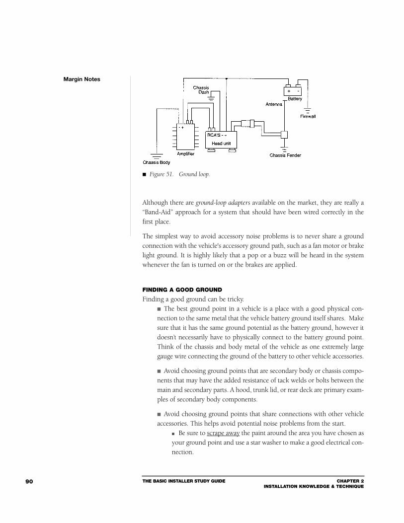
THE BASIC INSTALLER STUDY GUIDE CHAPTER 2INSTALLATION KNOWLEDGE & TECHNIQUE
90
Although there are ground-loop adapters available on the market, they are really a“Band-Aid” approach for a system that should have been wired correctly in thefirst place.
The simplest way to avoid accessory noise problems is to never share a groundconnection with the vehicle's accessory ground path, such as a fan motor or brakelight ground. It is highly likely that a pop or a buzz will be heard in the systemwhenever the fan is turned on or the brakes are applied.
FINDING A GOOD GROUND
Finding a good ground can be tricky. The best ground point in a vehicle is a place with a good physical con-nection to the same metal that the vehicle battery ground itself shares. Makesure that it has the same ground potential as the battery ground, however itdoesn’t necessarily have to physically connect to the battery ground point.Think of the chassis and body metal of the vehicle as one extremely largegauge wire connecting the ground of the battery to other vehicle accessories.
Avoid choosing ground points that are secondary body or chassis compo-nents that may have the added resistance of tack welds or bolts between themain and secondary parts. A hood, trunk lid, or rear deck are primary exam-ples of secondary body components.
Avoid choosing ground points that share connections with other vehicleaccessories. This helps avoid potential noise problems from the start.
Be sure to scrape away the paint around the area you have chosen asyour ground point and use a star washer to make a good electrical con-nection.
Margin Notes
Figure 51. Ground loop.
CHAPTER 2INSTALLATION KNOWLEDGE & TECHNIQUE
THE BASIC INSTALLER STUDY GUIDE 91
Star washers are better than flat washers for grounding because:1 Flat washers can trap contaminates between themselves and thegrounding surface, which increases contact resistance.
2 Star washers tend to bite into the grounding surface thus cleaning itand getting more surface area for lower contact resistance.
Always avoid using the factory headunit power and ground wiring. This wiring usually has inferior gauge and often does not go direct-ly to ground, but picks up grounds of other vehicle systems which areclustered together at one point. Although many standard installation procedures of headunits call fora “factory harness adapter,” systems with signal processors, multipleamplifiers, and/or significant amounts of headunit power may be moreprone to noise related problems by using factory headunit powerwiring. This can introduce clicks and pops in an audio system when othervehicle systems switch on and off. Factory wiring also runs in harnesses past other devices in the vehi-cle, which can radiate or couple noise into an audio system.
PROPER WIRE GAUGES
The purpose of a wire is to conduct electric current from one location to another.Poor system wiring can induce noise and cause overall poor performance.
The size of the power and ground cables (Kirchoffs’ current law) used tosupply battery power to an amplifier are of utmost concern.
Using too small a gauge cable to power an amp will limit the amountof current which an amp gets, thus limiting its performance. An inadequate wire size could melt the insulation off the cable andcould cause serious damage to your customer's vehicle. A large gauge, multi-stranded wire – with either a fuse or circuit break-er within 10 inches of the battery – is mandatory. American Wire Gauge (AWG) labeling of cable is somewhat confus-ing – the lower the number, the bigger the cable. For example, a #12wire is larger and will handle more current than a #16. A #22 gaugewire is much smaller than #14.
Margin Notes
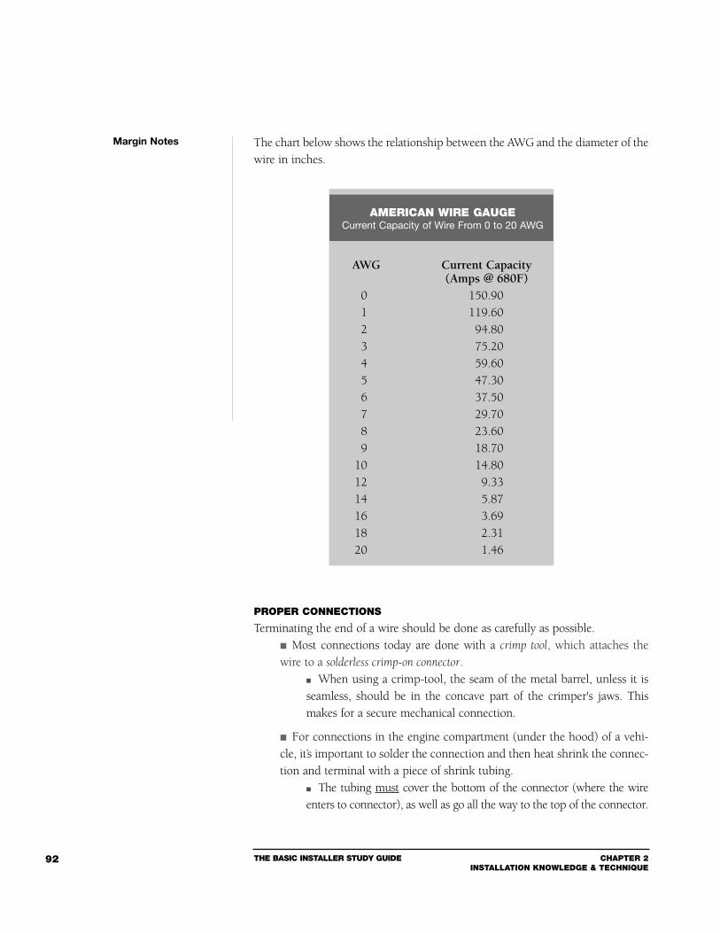
THE BASIC INSTALLER STUDY GUIDE CHAPTER 2INSTALLATION KNOWLEDGE & TECHNIQUE
92
The chart below shows the relationship between the AWG and the diameter of thewire in inches.
PROPER CONNECTIONS
Terminating the end of a wire should be done as carefully as possible. Most connections today are done with a crimp tool, which attaches thewire to a solderless crimp-on connector.
When using a crimp-tool, the seam of the metal barrel, unless it isseamless, should be in the concave part of the crimper's jaws. Thismakes for a secure mechanical connection.
For connections in the engine compartment (under the hood) of a vehi-cle, it’s important to solder the connection and then heat shrink the connec-tion and terminal with a piece of shrink tubing.
The tubing must cover the bottom of the connector (where the wireenters to connector), as well as go all the way to the top of the connector.
Margin Notes
AMERICAN WIRE GAUGECurrent Capacity of Wire From 0 to 20 AWG
AWG Current Capacity(Amps @ 680F)
0 150.901 119.602 94.803 75.204 59.605 47.306 37.507 29.708 23.609 18.70
10 14.8012 9.3314 5.8716 3.6918 2.3120 1.46
CHAPTER 2INSTALLATION KNOWLEDGE & TECHNIQUE
THE BASIC INSTALLER STUDY GUIDE 93
Cover as much of the connector as possible making a good weatherresistant seal.
When the connection is firmly attached to the firewall, it is good practiceto apply noncorrosive grease to the screw head.
This helps reduce possible corrosion of the screw head and the ter-minal.
The only drawback to crimping is that over a period of time, oxidation can buildup between the wire and the connectors. This oxidation causes a degradation inthe electrical connection. In other words, it causes an increase in resistance, whichwill hurt the overall performance of the unit involved.
Soldering is another alternative: Solder should be applied so that it flows over the connection.
For best results, the iron should be held below the wire while applying thesolder from above.
This allows the solder to flow from the top of the wire to the bottommore uniformly. Remember to heat the connector, not the wire. Two or three “balls” of solder (a cold solder joint) is not good enoughbecause they will contain air bubbles and either break off or have littleto no electrical connection value. A good solder joint should be smooth, shiny, and concave. It isimportant to remember that solder does not go from the liquid statedirectly to the solid state, but has a plastic state in between. During theplastic state, a cold solder joint can occur if the joint is moved.
Avoid using wire nuts. Wire nuts were designed for a stationary, stable environ-ment – like inside a house – not many houses are designed to accelerate, deceler-ate, or corner.
The wire nut will eventually fall off the wire leaving the exposed wiring toshort to ground or to a component.
Margin Notes
A good solder joint
should be smooth, shiny,
and concave.
THE BASIC INSTALLER STUDY GUIDE CHAPTER 2INSTALLATION KNOWLEDGE & TECHNIQUE
94
ANTENNAS
Most automobiles use one of six types of antennas:1 Fixed mast2 Power3 Collapsible mast (full length)4 Short collapsible mast (amplified)5 Windshield6 Diversity
Depending on the car, these antennas can be mounted through the top surface offenders, on the sides of fenders, through the windshield A-pillar, on the surface ofA--pillars, in the windshields, and along the back edges of the roof.
Antenna installation varies from car to car; however, proper mounting is crucial: When you’re selecting the right mounting location, refer to the guidelinessupplied by the manufacturer.
Mounting the antenna as far away from the engine as possible willusually reduce Radio Frequency Interference (RFI).
If the cable under the fender is in poor shape or is corroded, the groundbraid’s integrity can be compromised.
This will not allow the cable to reject radiated noise and will showup graphically on your AM band.
If the rockers under the fender are not firmly digging into metal, noise canbe generated.
When replacing an antenna, always remove any dirt which may haveaccumulated where the rockers will come in contact.
Most antennas (unless they’re electronically amplified) are approximately 31” long.This is said to be the best length for FM reception (1/2 of a quarter wavelength).
Guidelines for mounting an antenna:1 Check under the fender (front or back) for proper clearance.2 Mark your spot with a center punch or awl.3 Drill a pilot hole with a 1/8” bit.4 Then use a proper size hole saw at low-to-medium speed.5 Scrape away accumulated dirt under the fender to get the best ground possible.6 Apply a rustproof touch-up paint to the bare metal after drilling toinsure a rust free future in your installation.
Some vehicle manufactures are equipping their vehicles with power amplifiedantennas. These antennas increase performance; however, they have power leadswhich must be connected to a source of power that is live when the radio isturned on. This requires a connection to the headunit’s power antenna output(some headunits share this output with the remote amplifier turn-on).
Margin Notes
Most FM antennas
are 31” long.
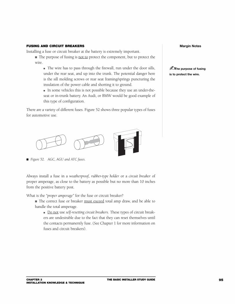
CHAPTER 2INSTALLATION KNOWLEDGE & TECHNIQUE
THE BASIC INSTALLER STUDY GUIDE 95
FUSING AND CIRCUIT BREAKERS
Installing a fuse or circuit breaker at the battery is extremely important. The purpose of fusing is not to protect the component, but to protect thewire.
The wire has to pass through the firewall, run under the door sills,under the rear seat, and up into the trunk. The potential danger hereis the sill molding screws or rear seat framing/springs puncturing theinsulation of the power cable and shorting it to ground. In some vehicles this is not possible because they use an under-the-seat or in-trunk battery. An Audi, or BMW would be good example ofthis type of configuration.
There are a variety of different fuses. Figure 52 shows three popular types of fusesfor automotive use.
Always install a fuse in a weatherproof, rubber-type holder or a circuit breaker ofproper amperage, as close to the battery as possible but no more than 10 inchesfrom the positive battery post.
What is the “proper amperage” for the fuse or circuit breaker? The correct fuse or breaker must exceed total amp draw, and be able tohandle the total amperage.
Do not use self-resetting circuit breakers. These types of circuit break-ers are undesirable due to the fact that they can reset themselves untilthe contacts permanently fuse. (See Chapter 1 for more information onfuses and circuit breakers).
Margin Notes
The purpose of fusing
is to protect the wire.
Figure 52. AGC, AGU and ATC fuses.
THE BASIC INSTALLER STUDY GUIDE CHAPTER 2INSTALLATION KNOWLEDGE & TECHNIQUE
96
Section 2Noise Troubleshooting
SYSTEM NOISE
Unintended noise entering a system can be an installer’s worst headache.Common sense and logical troubleshooting techniques, however, will help youthrough some of the most difficult problems.
The first three steps involved in troubleshooting noise are to:1 Identify2 Isolate3 Eliminate
IdentifyYou can identify the noise problem by making careful observations as to whatkind of problem is occurring. Ask yourself some simple questions:
1 What are the symptoms?2 What kind of noise is it?3 Does the noise run through the whole system?4 Does the noise go up and down with the volume control?5 When did the noise start?6 Does the noise rise and fall with engine speeds?7 How long has it existed?8 Is the noise affected by driving over bumps or dips?
IsolateOnce you’ve identified the problem, the next step is to isolate it to determine inwhat stage of the circuit the problem exists. A thorough investigation during theidentification process will help you out at this point.
A component failure is pretty easy to trace. A quick check of its operation and/orreplacement of the component will tell you if it is indeed the problem.
Note: A word of caution is in order here – do not make a habit of substituting parts dur-
ing this stage. If the problem is a short circuit or a reverse polarity condition, it may cost
you another part. Always check the electrical and mechanical environment around the
component in question first, then substitute.
Disconnecting and/or bypassing a component or section of the circuitry may alsobe necessary to isolate the problem.
Margin Notes
The first three steps
involved in troubleshooting
noise are to: Identify,
Isolate, and Eliminate.
A word of caution is in
order here. Do not make a
habit of substituting parts
during this stage. If the
problem is a short circuit or
a reverse polarity condition,
it may cost you another part.
CHAPTER 2INSTALLATION KNOWLEDGE & TECHNIQUE
THE BASIC INSTALLER STUDY GUIDE 97
EliminateOnce the problem has been identified and isolated, elimination will usuallyinvolve one or more of three variables:
1 Mechanical – involves changing the locations of components and/ormechanical connections, for proximity-related problems.
Mechanical alterations usually involve radiated noise andElectromagnetic Interference (EMI) noise as well as other prob-lems caused by the automotive environment.
2 Acoustical – involves phase, diffusion, interference, or loading problems. This type of problem may include mechanical problems as wellas require active or passive trimming of the system. (The First
Class Study Guide section on Autosound will cover troubleshoot-ing acoustical systems).
3 Electrical – deals with filtering, positive and negative DC paths, ACsignal paths, grounding, and all of the variables of the automotive elec-trical system.
Troubleshooting electrical systems can be a very complicatedprocess. It requires a basic knowledge of different types of testequipment such as an oscilloscope, LC bridge, signal generator,and distortion analyzer. A simple hand-held AM/FM radio is anexcellent piece of test equipment when troubleshooting RadioFrequency (RF) problems. The most basic tool, however, whenyou’re troubleshooting an electrical system, is a solid understand-ing of the electrical components involved (see Chapter 1).
TYPES OF NOISE PROBLEMS
System noise comes in many forms: Alternator whine is a whistling noise that responds in direct correlationto the RPM’s of the engine, and is usually the result of a voltage differentialcreated by more than one ground path or a poor ground path.
The best way to test for alternator whine is with the audio system onand the volume turned all the way down. Then “rev” the engine. If thewhine is heard, unplug the line inputs at the amp or crossover. If thewhine goes away, you've more than likely got a ground loop. Make sure all your grounds are assembled at one point only and thatamp mounting, crossover mounting, equalizer mounting, etc., are notallowing these components to touch ground.
Margin Notes
Alternator whine is a
whistling noise that responds
in direct correlation to the
RPM’s of the engine, and is
usually the result of a voltage
differential created by more
than one ground path or a
poor ground path.
THE BASIC INSTALLER STUDY GUIDE CHAPTER 2INSTALLATION KNOWLEDGE & TECHNIQUE
98
Cables that are too close together, or too close to stock wire looms, canpick up what is known as induced or coupled noise.
Proper wiring technique is essential – power and signal cables mustnot be run together and should be separated by at least 18 inches. If you have to route power and signal cables over one another, it'sbest that they cross at a 90 degree angle. This practice will reduce oreliminate induced noise.
You may have a component mismatch. The home audio industry has com-ponent values that are standardized. The autosound industry, however, doesnot share this standard.
Adjust the crossover, equalizer, and amplifier input levels (full gainis not a necessity) to get the components to “mate” with each other. Line isolators may be necessary.
If the noise persists when the line-level plugs are removed from the amp, then thenoise is probably coming in on the power line (though you could have a groundloop between the amp and a bad chassis ground point, or faulty product). Trymoving the location of the power cable away from such items as vehicle comput-ers and stock wire looms. If this does not help, a noise filter can be put on thepower line. Be advised, however, that an in-line passive noise filter will always dropthe voltage to the amplifier and may limit its performance.
A high amperage noise filter is a Band-Aid – not a cure – for a problem that is some-where else in the system.
If you must use a noise filter, remember that the majority of filters aremost effective when placed at the noise source.
Try to locate a noise filter close to the amp, crossover, or other devicethat needs filtering.
Radiated noise is the trickiest of all noise sources to eliminate. Noise can be radiated from the vehicle's ignition system (ignition coil,spark plugs, rotor) to such vehicle components as the radio antenna,radio, and the power harnesses in the vehicle. Noise can be radiated into power and signal cables by vehicle com-puters, fuel pumps, and key-in ignition buzzers. In these cases, the only way to eliminate the noise is to bypass thesesystems. To find the source of the noise, use a noise sniffer. Make sure you find the true source of the noise because noise cansometimes come from a secondary radiator.
Margin Notes
Cables that are too close
together, or too close to
stock wire looms, can pick
up what is known as induced
or coupled noise.
If you must use a noise
filter, remember that the
majority of filters are most
effective when placed at
the noise source.
CHAPTER 2INSTALLATION KNOWLEDGE & TECHNIQUE
THE BASIC INSTALLER STUDY GUIDE 99
The cure may be as simple as moving the secondary radiator awayfrom the primary radiator (i.e., moving a stock wire loom a few inchesfrom another wire loom).
Remember, most types of radiated noise cannot be eliminated, they can only bererouted or redirected.
Popping and clicking in an audio system is usually caused by componentsin the system sharing a common ground path with a multitude of vehiclesystems or components.
Brake pedals, fan motors, etc., can induce noise. Identify which devices are affecting the audio system, and reground thesystem to a “cleaner” ground. Adding a noise filter or polarized capacitor at the source of the noisewill also help. A good rule of thumb – avoid the constant 12-Volt power andground wires from the stock radio. The 12-Volt line usually comes from the fuse block, the noisiestpoint on the vehicle, and the ground is usually run to a common pointwith several vehicle accessories. Both are an open invitation to noiseproblems.
Substitution is the preferred method to find out how noise is entering a system. If you think a noise problem is coming in on the power cable, run anew one OUTSIDE of the vehicle, away from possible noise-producingvehicle items. The same can be done with line-level cables. (Remember: use highquality cables). If you think the noise is coming in on the power cable, disconnectit from the vehicle’s battery and connect a shop (bench) 12-Volt powersupply instead.
Substitution can save you the trouble of tearing the vehicle apart to find noise.
Margin Notes
Remember, most types
of radiated noise cannot
be eliminated, they can only
be rerouted or redirected.
Popping and clicking in
an audio system is usually
caused by components in
the system sharing a com-
mon ground path with a
multitude of vehicle
systems or components.
Substitution is the
preferred method to find
out how noise is entering
a system.
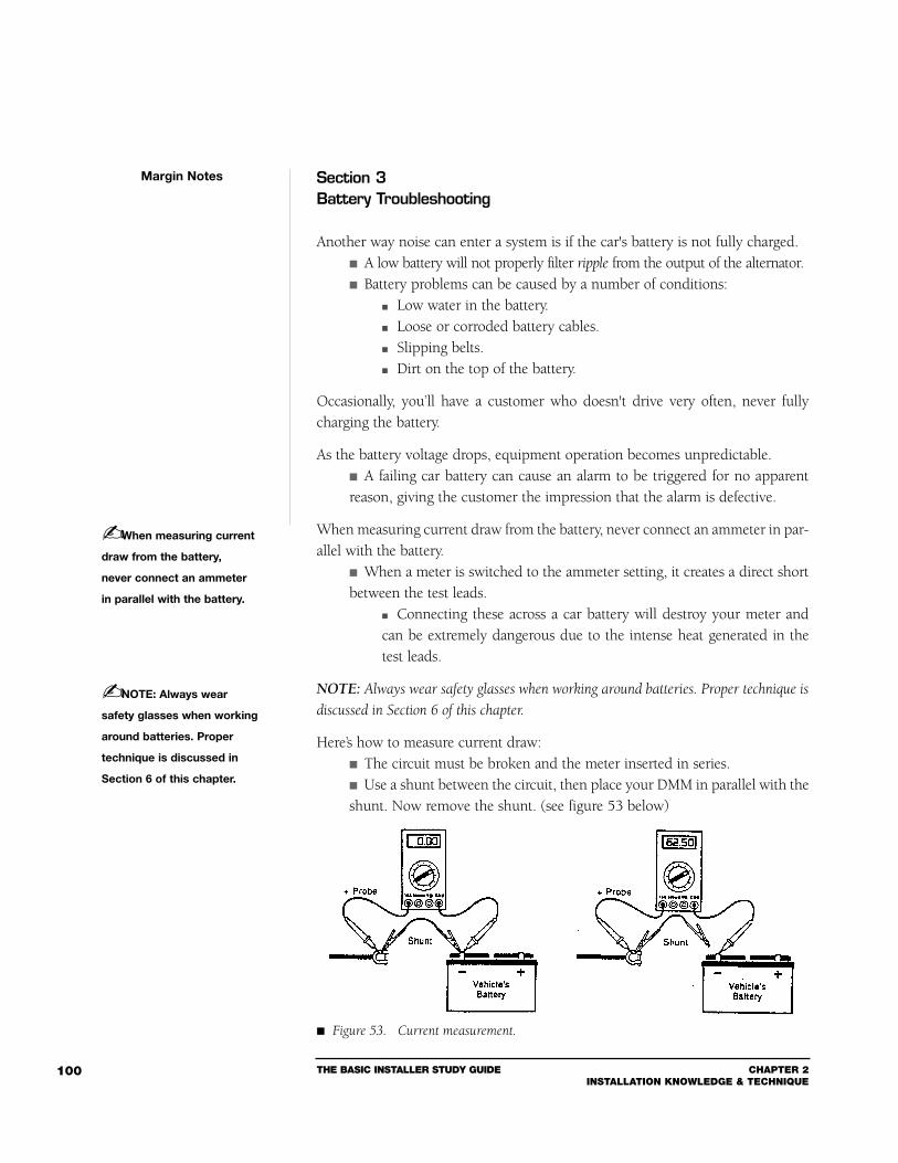
THE BASIC INSTALLER STUDY GUIDE CHAPTER 2INSTALLATION KNOWLEDGE & TECHNIQUE
100
Section 3Battery Troubleshooting
Another way noise can enter a system is if the car's battery is not fully charged. A low battery will not properly filter ripple from the output of the alternator. Battery problems can be caused by a number of conditions:
Low water in the battery. Loose or corroded battery cables. Slipping belts. Dirt on the top of the battery.
Occasionally, you’ll have a customer who doesn't drive very often, never fullycharging the battery.
As the battery voltage drops, equipment operation becomes unpredictable. A failing car battery can cause an alarm to be triggered for no apparentreason, giving the customer the impression that the alarm is defective.
When measuring current draw from the battery, never connect an ammeter in par-allel with the battery.
When a meter is switched to the ammeter setting, it creates a direct shortbetween the test leads.
Connecting these across a car battery will destroy your meter andcan be extremely dangerous due to the intense heat generated in thetest leads.
NOTE: Always wear safety glasses when working around batteries. Proper technique is
discussed in Section 6 of this chapter.
Here’s how to measure current draw: The circuit must be broken and the meter inserted in series. Use a shunt between the circuit, then place your DMM in parallel with theshunt. Now remove the shunt. (see figure 53 below)
Margin Notes
When measuring current
draw from the battery,
never connect an ammeter
in parallel with the battery.
NOTE: Always wear
safety glasses when working
around batteries. Proper
technique is discussed in
Section 6 of this chapter.
Figure 53. Current measurement.
CHAPTER 2INSTALLATION KNOWLEDGE & TECHNIQUE
THE BASIC INSTALLER STUDY GUIDE 101
All of the current the circuit is drawing is now passing through the leadsof your meter.
The following only happens if you break the circuit at either the positive or neg-ative terminal of the battery:
Any current drawn by any device in the car will go through your meter.
If you’re measuring 50 milliamps on the 200 milliamp scale and thenopen the door, the dome light will draw a couple of amps.
This is a 40 fold increase in current. Imagine what will happen if youtry to start the car and attempt to pull 350 Amps through your meter.
Some cars have a delay-off dome light and some alarms will draw more currentwhen they are first powered up.
If your meter does not have a high amp range, this can pose a problem. If this is the case, placement of a shunt across the test leads with awire of suitable gauge is essential. After the equipment has stabilized, remove the shunt.
To measure current drawn by devices installed with a power lead to the battery,simply remove the fuse and connect your meter there.
Start on the highest range your meter has and then work down to moresensitive ranges.
To measure current draw for the entire vehicle, remove one of the cablesfrom the battery.
It doesn’t matter which cable you remove (negative or positive),since the same amount of current flows in both leads. It’s often easier to remove the negative cable so you don’t have towork with all the accessory leads on the positive post.
If current drain exceeds 45 milliamps, pull the fuses out of your fuseholders at thebattery.
Pull the radio fuse out of the fusebox, or remove a pull-out radio. Make sure you’ve pulled the correct fuse by verifying that the sus-pect equipment is not operating. When you have found which fuse, when removed, stops the currentdraw, you have isolated the piece of equipment.
Remove any stereo equipment and bench test it to make sure you have found theproblem.
If the current draw is in the vehicle, advise the shop manager or the cus-tomer, depending on your situation.
Margin Notes
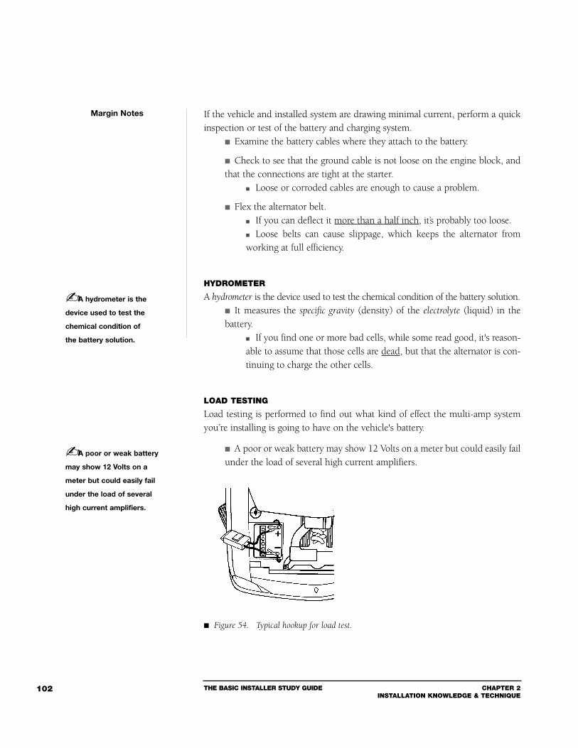
THE BASIC INSTALLER STUDY GUIDE CHAPTER 2INSTALLATION KNOWLEDGE & TECHNIQUE
102
If the vehicle and installed system are drawing minimal current, perform a quickinspection or test of the battery and charging system.
Examine the battery cables where they attach to the battery.
Check to see that the ground cable is not loose on the engine block, andthat the connections are tight at the starter.
Loose or corroded cables are enough to cause a problem.
Flex the alternator belt. If you can deflect it more than a half inch, it’s probably too loose. Loose belts can cause slippage, which keeps the alternator fromworking at full efficiency.
HYDROMETER
A hydrometer is the device used to test the chemical condition of the battery solution. It measures the specific gravity (density) of the electrolyte (liquid) in thebattery.
If you find one or more bad cells, while some read good, it's reason-able to assume that those cells are dead, but that the alternator is con-tinuing to charge the other cells.
LOAD TESTING
Load testing is performed to find out what kind of effect the multi-amp systemyou’re installing is going to have on the vehicle's battery.
A poor or weak battery may show 12 Volts on a meter but could easily failunder the load of several high current amplifiers.
Margin Notes
A hydrometer is the
device used to test the
chemical condition of
the battery solution.
A poor or weak battery
may show 12 Volts on a
meter but could easily fail
under the load of several
high current amplifiers.
Figure 54. Typical hookup for load test.
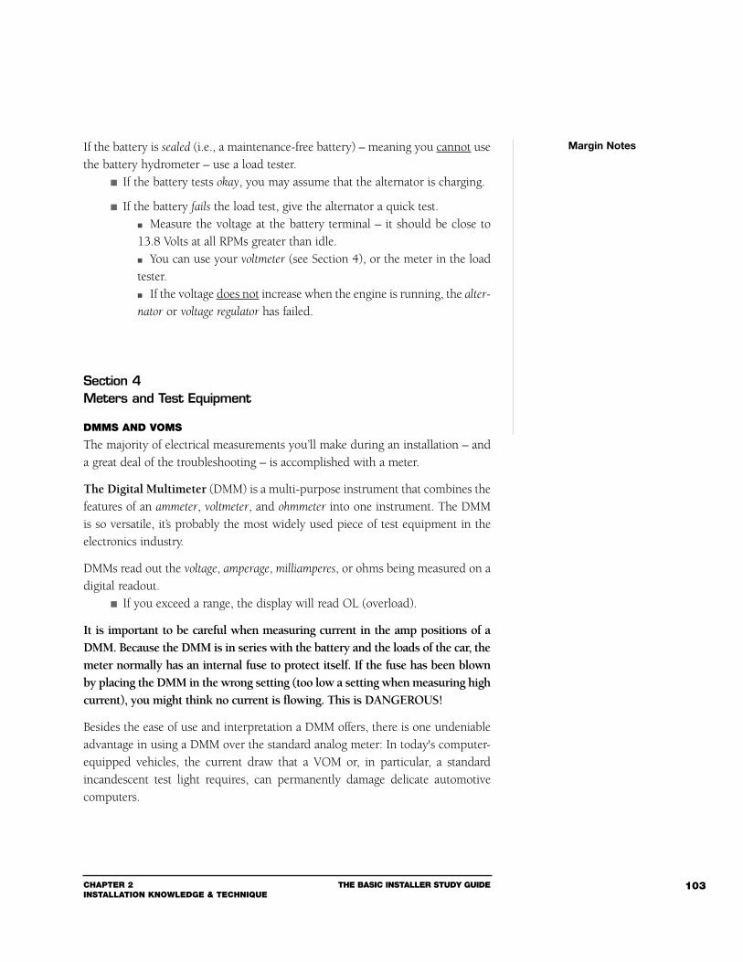
CHAPTER 2INSTALLATION KNOWLEDGE & TECHNIQUE
THE BASIC INSTALLER STUDY GUIDE 103
If the battery is sealed (i.e., a maintenance-free battery) – meaning you cannot usethe battery hydrometer – use a load tester.
If the battery tests okay, you may assume that the alternator is charging.
If the battery fails the load test, give the alternator a quick test. Measure the voltage at the battery terminal – it should be close to13.8 Volts at all RPMs greater than idle. You can use your voltmeter (see Section 4), or the meter in the loadtester. If the voltage does not increase when the engine is running, the alter-
nator or voltage regulator has failed.
Section 4Meters and Test Equipment
DMMS AND VOMS
The majority of electrical measurements you’ll make during an installation – anda great deal of the troubleshooting – is accomplished with a meter.
The Digital Multimeter (DMM) is a multi-purpose instrument that combines thefeatures of an ammeter, voltmeter, and ohmmeter into one instrument. The DMMis so versatile, it’s probably the most widely used piece of test equipment in theelectronics industry.
DMMs read out the voltage, amperage, milliamperes, or ohms being measured on adigital readout.
If you exceed a range, the display will read OL (overload).
It is important to be careful when measuring current in the amp positions of aDMM. Because the DMM is in series with the battery and the loads of the car, themeter normally has an internal fuse to protect itself. If the fuse has been blownby placing the DMM in the wrong setting (too low a setting when measuring highcurrent), you might think no current is flowing. This is DANGEROUS!
Besides the ease of use and interpretation a DMM offers, there is one undeniableadvantage in using a DMM over the standard analog meter: In today's computer-equipped vehicles, the current draw that a VOM or, in particular, a standardincandescent test light requires, can permanently damage delicate automotivecomputers.
Margin Notes
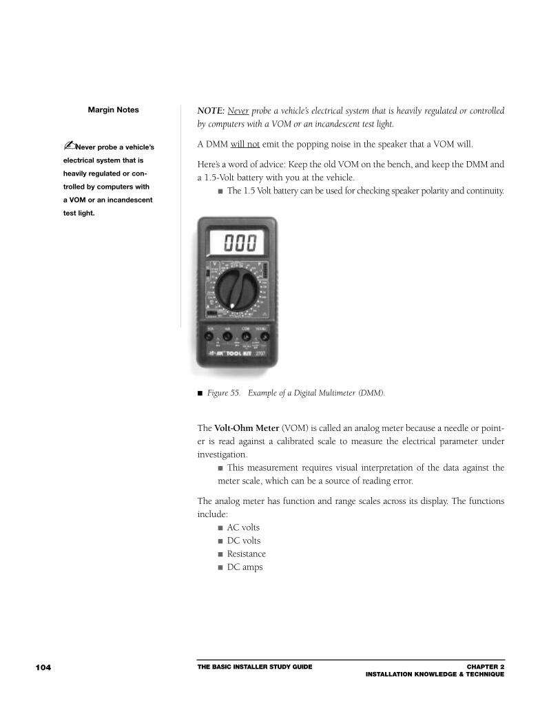
THE BASIC INSTALLER STUDY GUIDE CHAPTER 2INSTALLATION KNOWLEDGE & TECHNIQUE
104
NOTE: Never probe a vehicle’s electrical system that is heavily regulated or controlled
by computers with a VOM or an incandescent test light.
A DMM will not emit the popping noise in the speaker that a VOM will.
Here’s a word of advice: Keep the old VOM on the bench, and keep the DMM anda 1.5-Volt battery with you at the vehicle.
The 1.5 Volt battery can be used for checking speaker polarity and continuity.
The Volt-Ohm Meter (VOM) is called an analog meter because a needle or point-er is read against a calibrated scale to measure the electrical parameter underinvestigation.
This measurement requires visual interpretation of the data against themeter scale, which can be a source of reading error.
The analog meter has function and range scales across its display. The functionsinclude:
AC volts DC volts Resistance DC amps
Margin Notes
Never probe a vehicle’s
electrical system that is
heavily regulated or con-
trolled by computers with
a VOM or an incandescent
test light.
Figure 55. Example of a Digital Multimeter (DMM).
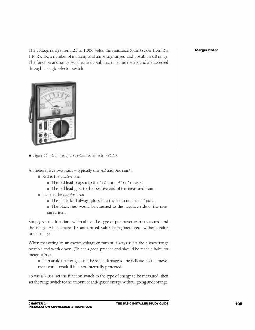
CHAPTER 2INSTALLATION KNOWLEDGE & TECHNIQUE
THE BASIC INSTALLER STUDY GUIDE 105
The voltage ranges from .25 to 1,000 Volts; the resistance (ohm) scales from R x1 to R x 1K; a number of milliamp and amperage ranges; and possibly a dB range.The function and range switches are combined on some meters and are accessedthrough a single selector switch.
All meters have two leads – typically one red and one black: Red is the positive lead.
The red lead plugs into the “+V, ohm, A” or “+” jack. The red lead goes to the positive end of the measured item.
Black is the negative lead. The black lead always plugs into the “common” or “-” jack. The black lead would be attached to the negative side of the mea-sured item.
Simply set the function switch above the type of parameter to be measured andthe range switch above the anticipated value being measured, without goingunder range.
When measuring an unknown voltage or current, always select the highest rangepossible and work down. (This is a good practice and should be made a habit formeter safety).
If an analog meter goes off the scale, damage to the delicate needle move-ment could result if it is not internally protected.
To use a VOM, set the function switch to the type of energy to be measured, thenset the range switch to the amount of anticipated energy, without going under-range.
Margin Notes
Figure 56. Example of a Volt-Ohm Multimeter (VOM).
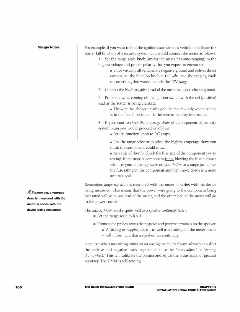
For example, if you want to find the ignition start wire of a vehicle to facilitate thestarter kill function of a security system, you would connect the meter as follows:
1 Set the range scale knob (unless the meter has auto-ranging) to thehighest voltage and proper polarity that you expect to encounter.
Since virtually all vehicles are negative ground and deliver directcurrent, set the function knob at DC volts, and the ranging knobto something that would include the 12V range.
2 Connect the black (negative) lead of the meter to a good chassis ground.
3 Probe the wires coming off the ignition switch with the red (positive)lead as the starter is being cranked.
The wire that shows a reading on the meter – only when the keyis in the “start” position – is the wire to be relay interrupted.
4 If you want to check the amperage draw of a component or securitysystem brain you would proceed as follows:
Set the function knob to DC amps.
Use the range selector to select the highest amperage draw youthink the component could draw. As a rule of thumb, check the fuse size of the component you’retesting. If the suspect component is not blowing the fuse it comeswith, set your amperage scale on your VOM to a range just abovethe fuse rating on the component and then move down to a moreaccurate scale.
Remember, amperage draw is measured with the meter in series with the devicebeing measured. This means that the power wire going to the component beingmeasured will go to one lead of the meter, and the other lead of the meter will goto the power source.
The analog VOM works quite well as a speaker continuity tester. Set the range scale to R x 1.
Connect the probes across the negative and positive terminals on the speaker. A clicking or popping noise – as well as a reading on the meter‘s scale– will inform you that a speaker has continuity.
Note that when measuring ohms on an analog meter, it’s always advisable to short
the positive and negative leads together and use the “ohms adjust” or “zeroing
thumbwheel.” This will calibrate the pointer and adjust the ohms scale for greatestaccuracy. The DMM is self-zeroing.
THE BASIC INSTALLER STUDY GUIDE CHAPTER 2INSTALLATION KNOWLEDGE & TECHNIQUE
106
Margin Notes
Remember, amperage
draw is measured with the
meter in series with the
device being measured.
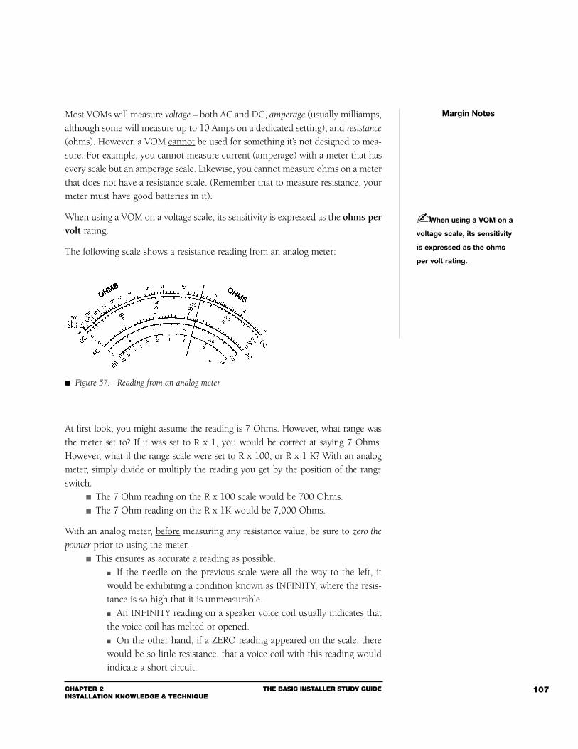
CHAPTER 2INSTALLATION KNOWLEDGE & TECHNIQUE
THE BASIC INSTALLER STUDY GUIDE 107
Most VOMs will measure voltage – both AC and DC, amperage (usually milliamps,although some will measure up to 10 Amps on a dedicated setting), and resistance
(ohms). However, a VOM cannot be used for something it’s not designed to mea-sure. For example, you cannot measure current (amperage) with a meter that hasevery scale but an amperage scale. Likewise, you cannot measure ohms on a meterthat does not have a resistance scale. (Remember that to measure resistance, yourmeter must have good batteries in it).
When using a VOM on a voltage scale, its sensitivity is expressed as the ohms pervolt rating.
The following scale shows a resistance reading from an analog meter:
At first look, you might assume the reading is 7 Ohms. However, what range wasthe meter set to? If it was set to R x 1, you would be correct at saying 7 Ohms.However, what if the range scale were set to R x 100, or R x 1 K? With an analogmeter, simply divide or multiply the reading you get by the position of the rangeswitch.
The 7 Ohm reading on the R x 100 scale would be 700 Ohms. The 7 Ohm reading on the R x 1K would be 7,000 Ohms.
With an analog meter, before measuring any resistance value, be sure to zero the
pointer prior to using the meter. This ensures as accurate a reading as possible.
If the needle on the previous scale were all the way to the left, itwould be exhibiting a condition known as INFINITY, where the resis-tance is so high that it is unmeasurable. An INFINITY reading on a speaker voice coil usually indicates thatthe voice coil has melted or opened. On the other hand, if a ZERO reading appeared on the scale, therewould be so little resistance, that a voice coil with this reading wouldindicate a short circuit.
Margin Notes
When using a VOM on a
voltage scale, its sensitivity
is expressed as the ohms
per volt rating.
Figure 57. Reading from an analog meter.
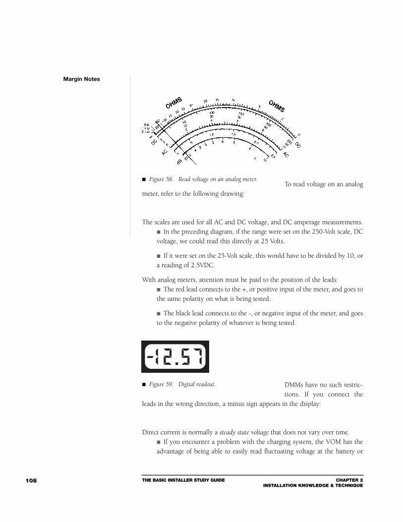
THE BASIC INSTALLER STUDY GUIDE CHAPTER 2INSTALLATION KNOWLEDGE & TECHNIQUE
108
To read voltage on an analogmeter, refer to the following drawing:
The scales are used for all AC and DC voltage, and DC amperage measurements. In the preceding diagram, if the range were set on the 250-Volt scale, DCvoltage, we could read this directly at 25 Volts.
If it were set on the 25-Volt scale, this would have to be divided by 10, ora reading of 2.5VDC.
With analog meters, attention must be paid to the position of the leads: The red lead connects to the +, or positive input of the meter, and goes tothe same polarity on what is being tested.
The black lead connects to the -, or negative input of the meter, and goesto the negative polarity of whatever is being tested.
DMMs have no such restric-tions. If you connect the
leads in the wrong direction, a minus sign appears in the display:
Direct current is normally a steady state voltage that does not vary over time. If you encounter a problem with the charging system, the VOM has theadvantage of being able to easily read fluctuating voltage at the battery or
Margin Notes
Figure 58. Read voltage on an analog meter.
Figure 59. Digital readout.
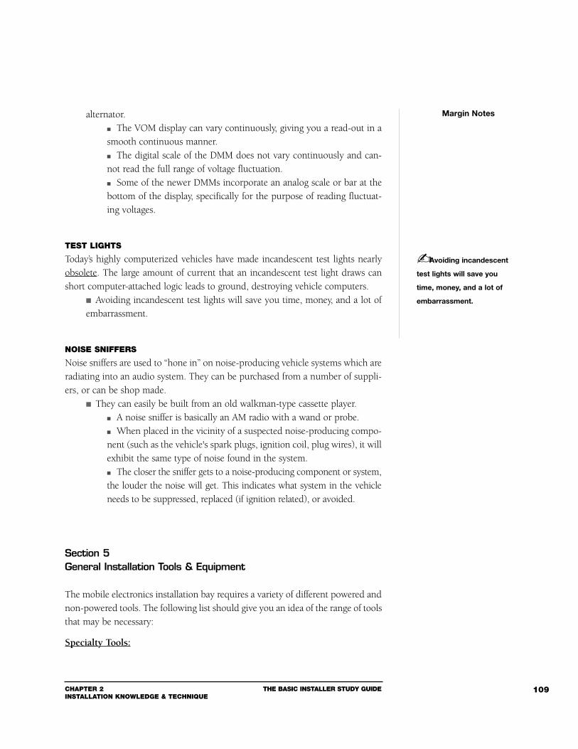
CHAPTER 2INSTALLATION KNOWLEDGE & TECHNIQUE
THE BASIC INSTALLER STUDY GUIDE 109
alternator. The VOM display can vary continuously, giving you a read-out in asmooth continuous manner. The digital scale of the DMM does not vary continuously and can-not read the full range of voltage fluctuation. Some of the newer DMMs incorporate an analog scale or bar at thebottom of the display, specifically for the purpose of reading fluctuat-ing voltages.
TEST LIGHTS
Today’s highly computerized vehicles have made incandescent test lights nearlyobsolete. The large amount of current that an incandescent test light draws canshort computer-attached logic leads to ground, destroying vehicle computers.
Avoiding incandescent test lights will save you time, money, and a lot ofembarrassment.
NOISE SNIFFERS
Noise sniffers are used to “hone in” on noise-producing vehicle systems which areradiating into an audio system. They can be purchased from a number of suppli-ers, or can be shop made.
They can easily be built from an old walkman-type cassette player. A noise sniffer is basically an AM radio with a wand or probe. When placed in the vicinity of a suspected noise-producing compo-nent (such as the vehicle's spark plugs, ignition coil, plug wires), it willexhibit the same type of noise found in the system. The closer the sniffer gets to a noise-producing component or system,the louder the noise will get. This indicates what system in the vehicleneeds to be suppressed, replaced (if ignition related), or avoided.
Section 5General Installation Tools & Equipment
The mobile electronics installation bay requires a variety of different powered andnon-powered tools. The following list should give you an idea of the range of toolsthat may be necessary:
Specialty Tools:
Margin Notes
Avoiding incandescent
test lights will save you
time, money, and a lot of
embarrassment.

THE BASIC INSTALLER STUDY GUIDE CHAPTER 2INSTALLATION KNOWLEDGE & TECHNIQUE
110
1 Door/Window crank handle spring clip removal tool2 Door Panel clip removal tool3 Hole saw bits 3/4”, 1”, 1 1/4”4 Unibits (sometimes called step drill bit)5 Special theft-resistant shaftnut removal socket6 Six-Point General Motors screwdriver bit
General Equipment:1 Crimp tool – multiple gauge2 Drill – variable-speed, reversible3 Drill bits – high-speed, metal 1/8” to 1/2”4 Dremel moto-tool and accessories (for plastic alterations)5 Electrical tape (Scotch #33+)6 Hand or Power nibbler7 HotKnife8 Magnet – mechanic type or other9 Magnetic Screw drivers – Phillips #1, 2, 3; slotted #1 and 210 Marking set – pencils, pens, chalk, laundry type markers (indelible)11 Mechanics Mirror12 Metric allen wrench set13 Pliers – channel lock, needle nose, and standard14 Punch – 1/8” – 1/4”15 Putty knife – 1”16 Right and left handed metal sheers (aviation snips)17 Sabre saw and bits-variable speed18 Scratch awl (scribe)19 Single hand hack saw20 Socket wrenches – metric, 1/4” and 3/8” drive, 5mm – l4mm sock
ets. S.A.E. 1/4” – 5/8” sockets21 Soldering gun with rosin flux solder22 Standard allen wrench set23 Tape measure – metric and inch24 Vacuum cleaner – portable, or wet-dry canister type25 Volt-Ohm Meter (VOM)26 Digital Multimeter (DMM)27 Wire stripper – multi gauge28 Wire ties29 X-Acto knife, razor blades, utility knife
Margin Notes
CHAPTER 2INSTALLATION KNOWLEDGE & TECHNIQUE
THE BASIC INSTALLER STUDY GUIDE 111
30 X-Acto razor saw blades31 Heat gun
Shop Equipment for Custom Fabrication:1 Air compressor2 Dual trace oscilloscope3 Extension boxes for 120V AC power4 Fabrication components (grille cloth, carpet, glue, etc.)5 Large glue gun6 Large current capacity battery charger7 Portable fluorescent lighting8 Photographic equipment9 Realtime analyzer (Fast Fourier Transform System)10 Signal generator (RF and AF)11 Shop tools:
a. Drill Pressb. Grinderc. Milling machined. Routere. Sanderf. Table sawg. Vises
12 Soldering stations13 Ventilated booth – for painting and fiberglass fabrication14 Welding torch15 Work benches (carpeted for door panels, plain for wood working)16 Computer for speaker enclosure design
NON-POWERED HAND TOOLS
In the category of non-powered hand tools, essentials include the following: A full set of straight blade and Phillips tip screwdrivers.
#2 Phillips is the most common, even for screw guns.
A full set of S.A.E. and metric sockets, along with the appropriate ratchets,extensions, “U” joints, and handles to facilitate every conceivable angle.
A 10mm socket is the most commonly used socket for Europeanand Japanese cars.
A full set of open-end wrenches, both S.A.E. and metric, as well asadjustable wrenches.
Margin Notes
THE BASIC INSTALLER STUDY GUIDE CHAPTER 2INSTALLATION KNOWLEDGE & TECHNIQUE
112
A good pair of diagonal cutters (commonly referred to as dikes).
A set of long-nose pliers, regular pliers, vice grips, and crimping tools.
A set of shaft sockets (although DIN-sized radios are rapidly replacing theshaft radio, shaft sockets are still invaluable).
Shaft sockets are like regular sockets, but have longer shafts with nointernal obstacles to inhibit sliding over the shaft.
A full set of files – both rough and finish.
Keyhole saws, hack saws, hack saw blades, and razor knives.
A full set of aviation metal shears (also called tin snips). Be sure to get the left cutting for counterclockwise cutting, right cutting
for clockwise cutting, and the straight cutting for straight cuts.
A good pair of industrial-duty shop scissors for cutting fabrics.
A full set of metric and standard allen (hex) key wrenches, as well as a full setof torx wrenches. They are not interchangeable, so you'll need them both.
A small level to make sure speakers are straight in doors and on rear decks.
POWERED HAND TOOLS
This category usually includes the following:
Drills: Cordless drills are most common.
Use drills – either cordless or cabled –which have variable speed trigger
controls. This allows you to control the speed at different times in the drillingprocedure.
If you use a drill as a screw gun, your best choice is a cordless drill withvariable speed, reversing capability, and a clutch.
One of the handiest drills is the right-angle drill, which enables you to getinto areas that a regular drill cannot.
If you’re going to be drilling a 3/8” hole through double metal, the lowtorque and slow rpm of a cordless drill will take a lot more time; a 3/8” elec-
tric, high rpm drill will cut right through the metal. Too high of a speed can burn up and destroy drill bits.
Margin Notes
If you use a drill as a
screw gun, your best
choice is a cordless drill
with variable speed,
reversing capability,
and a clutch.

CHAPTER 2INSTALLATION KNOWLEDGE & TECHNIQUE
THE BASIC INSTALLER STUDY GUIDE 113
When trying to turn large hole saws, advancing to a 1/2” drill, 1 hp or bet-ter, is usually necessary to provide the necessary torque.
Jigsaw/Sabre Saw: These saws are used for cutting metal, wood, and plastics and are avail-able as cordless models and offer variable speed.
Be sure to use the proper blade for the material being cut. Fine-toothed blades should be used for cutting metal and plastic;coarse blades for wood.
Always take safety precautions when using this type of saw, especiallywhen cutting corrugated metal panels.
Eye protection is a must.
Hand Router and Power Saw: These are required for woodworking, and should be operated by onlyknowledgeable and skilled installers or woodworkers.
Soldering Iron: Soldering irons can be the standard Weller 8200 soldering gun or cordlessmodel (Ultra torch UTS 100). Be careful though – high wattage guns candamage PC boards and small connectors.
A 25-40 Watt pencil-type soldering iron and stand should be handy onthe bench.
LARGE SHOP TOOLS
This category includes: A table saw, if you’re building a lot of speaker enclosures and custom panels.
A drill press is desirable, but not necessary.
Some shops like to use air tools instead of, or in combination with, electric handtools. If you’re using air tools, make sure the compressor and tank assembly areup to the capacity of the work load asked of it.
SPECIALTY TOOLS
Dremel Moto-Tool: This device is about as small as an electric razor and has every conceiv-able attachment.
A Dremel tool can be used as a small electric drill or a rotary file. With a saw-blade attachment, it will easily cut through ABS plastic,
Margin Notes
THE BASIC INSTALLER STUDY GUIDE CHAPTER 2INSTALLATION KNOWLEDGE & TECHNIQUE
114
but it usually doesn’t have the power necessary to cut or grind metal.For such jobs, use an air or electric hand held grinder.
Power/Hand Nibbler: A hand nibbler takes small, rectangle-size pieces out of metal.
A disadvantage of the hand nibbler is that it is heavy and sometimesawkward to use. Bosch, Makita, and other manufacturers offer a power nibbler that ismuch less taxing on the hands, but does leave small crescent shapedpieces of metal which can be very dangerous and should be cleaned upas soon as you are finished cutting.
Signal Amplifier (Head Amp): This is used to boost the voltage level of a preamp signal.
Commonly used when the output voltage of a headunit is too low toadequately drive an electronic crossover or amplifier. It’s installed between the output of the head unit and the input of thecrossover/amp. The output gain is usually adjustable.
EMR Detector: This tool is used to find the source of low frequency tape head interfer-ence, or EMR, Electro-Magnetic Radiation.
Speaker-Level Adapter/Converter: This device is used to convert the speaker outputs of any head unit intoline-level or preamp level leads.
The benefits include a much lower noise and distortion levels. The preamp level can be connected to other components in the sys-tem via regular shielded leads (RCA cables).
CUTTING TECHNIQUES
Wood:Wood can be cut with a sabre saw (jig saw), a regular crosscut saw, a keyhole saw,or a table saw:
When using a sabre/jig saw, a rougher-toothed blade is preferable to a finer--toothed blade.
To smooth out roughly cut wood (speaker holes, for example), usea wood file.
The best way to cut speaker holes in wood is with a hole saw.
Margin Notes
CHAPTER 2INSTALLATION KNOWLEDGE & TECHNIQUE
THE BASIC INSTALLER STUDY GUIDE 115
Make sure you have an electric drill with enough torque to handlethe job, and that your hole saw blade is sharp.
A router with a hole cutting attachment – if properly used – makes a per-fect hole ready for rabbitting and speaker installation. It is also quicker thanthe other methods.
Metal:Metal can be cut with a hack saw, aviation shears (tin snips), or a jig/sabre sawwith an appropriate fine-toothed blade.
For either wood or metal, a drill – with usually a 3/8” bit – can be usedto drill a starter hole. This allows the sabre saw blade, or tin snips, to getstarted.
Care should always be taken not to “push” a jig saw blade as it cuts. Thiscould cause it to heat up and burn its way through a hole instead of cutting.The saw blade could also break, injuring the user or damaging the vehicle.
An air chisel or metal nibbler should be used by only an experiencedinstaller.
Upholstery:Upholstery must only be cut with a razor knife or a type of razor blade.
A drill can damage the fabric if it is not first cut away with a knife.
Carpeting can wrap around a drill, creating a hazard when it unweaves.
Vinyl can stretch and rip apart if caught by a hot, high rpm drill bit.
Section 6Shop Safety
You’ve probably heard the popular slogan, “Safety First.”
This is especially true for installers – particularly when you have three jobs wait-ing…and it’s four o’clock on Friday afternoon!
In the real world, safety often comes last.
Margin Notes

THE BASIC INSTALLER STUDY GUIDE CHAPTER 2INSTALLATION KNOWLEDGE & TECHNIQUE
116
It’s important to stress, however, that the installation bay offers a variety of haz-ards. Electric shock, hazardous chemicals, and sharp tools are just a few.
The Occupational Safety and Health Administration (OSHA) is the governmentagency that regulates on-the-job safety.
OSHA requires that all employers maintain a safe and healthy work envi-ronment.
The Code of Federal Regulations (CFR) lists safety and health standards,and employers face stiff fines if these standards are not followed.
While the shop owner is ultimately responsible for accidents, safety begins withthe individual. Therefore, a properly maintained attitude is your most important“tool” to help promote shop efficiency and safety.
SAFETY PRACTICES
The installation bay is no place for playing games or fooling around. Protect your-self from horseplay that can lead to accidents, and always wear the appropriategear before you begin a job. You will only lose that right eye or index finger once,and after the fact is too late to start being careful.
Eyes:When using power tools – such as power nibblers, routers, jig/sabre saws, radialarm saws, Dremel tools, etc. – Always wear safety glasses or goggles.
Some installers think wearing safety glasses makes them look “un-cool.”However, looking “cool” does little good if you’re permanently blinded byflying wood or metal chips.
Ears:OSHA has specific regulations for hearing protection. Listening to a sound system
Margin Notes
The Occupational Safety
and Health Administration
(OSHA) is the government
agency that regulates on-
the-job safety.
Always wear safety
glasses or goggles.
OSHA has specific regu-
lations for hearing protection.
Listening to a sound system
playing at 100 dBA SPL for
two hours will start to cause
hearing damage.NOISE EXPOSURE CHART
Sound Level (dBA) Maximum 24-Hour ExposureOccupational Nonoccupational
80 4 hr.85 2 hr.90 8 hr. 1 hr.95 4 hr. 30 min.
100 2 hr. 15 min.105 1 hr. 8 min.110 30 min. 4 min.115 15 min. 2 min.120 0 min. 0 min.

CHAPTER 2INSTALLATION KNOWLEDGE & TECHNIQUE
THE BASIC INSTALLER STUDY GUIDE 117
playing at 100 dBA SPL for two hours will start to cause hearing damage. If you’re constantly exposed to high decibel sound, wear earplugs or earprotection.
Respiratory:When working around sawdust or other airborne material, always wear a dustmask. Fiberglass and particle board are especially hazardous. The glue in particleboard is toxic, and fiberglass can cause severe skin irritation and lung damage ifit is inhaled.
When working with lead based solder, it should never be heated in excess of1000°F, at this point the solder becomes vaporized and emits hazardous vapor-ized lead oxide. Be sure to check the soldering iron temperature rating before sol-dering. Always solder in a well ventilated area.
Hands:Use gloves – full or partial – to protect your fingers and skin from being torn, cut,or burned.
Be particularly careful when working with large power tools.
SAFETY AROUND BATTERIES
By their very nature, batteries present a number of hazards. Chemical reactionstaking place inside of batteries generate flammable vapors. Therefore, never strikea match, a lighter, or anything that creates a spark or flame near a battery.
Although most modern batteries are sealed, older batteries still have vent capswhich need to be opened to be filled with distilled water.
While working around battery fluids, take extreme care not to come incontact with the main chemical ingredient, sulfuric acid.
Sulfuric acid is highly volatile, and will burn through clothing andskin, not to mention what can happen if it comes in contact with eyes.
SAFE TOOL USE
Make sure you know how to properly handle any tool – powered or not – beforeyou pick it up.
If improperly used, the air chisel is the most dangerous tool in the shop. Just the noise generated by this tool is enough to damage hearing ifprotection is not used. If proper precautions are not taken, a window can shatter in a door
Margin Notes
When working around
sawdust or other airborne
material, always wear a
dust mask.
Use gloves – full or partial
– to protect your fingers and
skin from being torn, cut,
or burned.
Never strike a match,
a lighter, or anything that
creates a spark or flame
near a battery.
Sulfuric acid is highly
volatile, and will burn
through clothing and skin,
not to mention what can
happen if it comes in
contact with eyes.
THE BASIC INSTALLER STUDY GUIDE CHAPTER 2INSTALLATION KNOWLEDGE & TECHNIQUE
118
and the rear window seal can have its integrity diminished due to thevibrations caused by an improperly used air chisel on a rear deck.
Dikes, long nose pliers, and crimp tools should have insulated handles. These are insulated not only for your comfort in reducing blisters fromcrimping and cutting all day, but to insulate you from electrical shock,should you accidentally hit a live wire or battery terminal.
FIRE EXTINGUISHERS
The laws of most states, cities, and counties require any shop which is workingon motor vehicles to have at least one fire extinguisher on the premises. Finesand/or possible jail sentences await those who refuse to comply with this law.
Most fire extinguishers work by removing the source of oxygen from the fire. Thetypes of extinguishers are noted as follows:
Type A – for wood and paper Type B – for oil and flammable liquids Type C – for fires of an electrical nature Halon – for all types of fires
The extinguisher best suited for a mobile electronics shop is the Halon type. Alwaysmake sure that the extinguisher is serviced at the appropriate interval, according tothe tag which was affixed to it during the last inspection or recharging.
Should you be unfortunate enough to have to fight a fire: Always point the nozzle on the extinguisher toward the base of the flames– not the burning material.
Only attempt to fight small, controllable fires. If a fire looks as though it’s getting out of hand, always contact thefire department. Never try to fight larger fires on your own. Remember, what may “look” like a fire may be only the insulationmelting off a wire, so don’t panic and reach for the fire extinguisher. Thebills to pay for cleaning a vehicle's interior can easily eat into profits.
CLEANING THE SHOP
Keeping the shop clean is also a part of safety, to say nothing about professionalism. A clean shop reassures the customers that they’ve made the right choiceabout your services.
Follow these guidelines:
Margin Notes
The extinguisher best
suited for a mobile electron-
ics shop is the Halon type.
CHAPTER 2INSTALLATION KNOWLEDGE & TECHNIQUE
THE BASIC INSTALLER STUDY GUIDE 119
Floors should be swept up as often as possible.
Reels of cable should be put back on their racks. Boxes that equipment came in should be put in the owner’s car or prop-erly recycled.
When cleaning up metal chips from power nibblers, or other tools, neverleave them on the floor to be swept up later.
These chips can find their way into customers’ tires, the interior oftheir cars, and the bottoms of your shoes. An old magnet can easily pickup stray nibbler chips to keep themfrom being tracked all over the shop.
A heavy-duty shop vac is essential in every shop.
FIRST AID
Try as we may to operate safely, the occasional accident will happen. Every phone in the shop should have the number of the nearest hospitalemergency room, police department, and fire department.
Every shop should have a first aid cabinet well stocked with bandages, adhesivetape, antibiotic first aid cream, eye wash, iodine, and alcohol.
These are available at medical supply houses and industrial supply houses.
The cabinet should be kept at a convenient, central location.
It’s advisable that one or more of your crew knows basic first aid and CPR.
Finally, because installers work with a lot of rusty metal, screws, and other unsa-vory items, you should get a tetanus shot every seven years.
Section 7Troubleshooting Guide
OVERALL
The customer comes to you with a physical problem (scratched paint, dirtyor torn interior, etc.) after the installation:
Review the “vehicle check-out” form with the client. Show them where the damage was noted on the form prior to theinstallation (and that the client signed that form before work was started.)
Margin Notes
THE BASIC INSTALLER STUDY GUIDE CHAPTER 2INSTALLATION KNOWLEDGE & TECHNIQUE
120
If you – or someone in your shop – did the damage, take responsi-bility and get it repaired.
The customer returns a year after the installation with a question and/or problem: Refer to the job log (which should be kept on file). It should include:
Wire codes for installing alarms. Wire colors for hooking up power supply leads and power antennas. Enclosure sizes for subwoofers in specific automobiles. Templates that are made for special head units, antenna, and speakerinstallations. Information on raw-materials sourcing, product sourcing, and peopleto contact in case of installation problems.
NOISE PROBLEMS
The three keys to noise problems:1 Identify 2 Isolate 3 Eliminate
How to identify the problem:1 What are the symptoms?2 What kind of noise is it?3 Does the noise run through the whole system?4 Does the noise go up and down with the volume control?5 When did the noise start?6 Does the noise rise and fall with engine speeds?7 How long has it existed?8 Is the noise affected by driving over bumps or dips?
Isolate:Once you have identified the problem, the next step is to isolate it to determinein what stage of the circuit the problem exists.
Eliminate:Here are some suggestions to help you eliminate various “noise” problems:
Check that the power and signal leads are run away from each other. Is the battery lead crossing over other vehicle wiring? Is your wiring next to any factory wiring harnesses? Check for passive crossovers installed near factory wiring harnesses.
Is the power source noise-free?
Margin Notes
CHAPTER 2INSTALLATION KNOWLEDGE & TECHNIQUE
THE BASIC INSTALLER STUDY GUIDE 121
Does the power source have enough current-carrying capacity for the uniteach wire will be powering?
Are the speaker wires and line--level signal leads on the opposite side ofthe vehicle?
If this can’t be done, try to keep power and signal cables as far apartfrom each other as possible – or a minimum of 18 inches. If you have to route power and signal cables over one another, it’sbest that they cross at a 90 degree angle.
Is power being accessed from the fuse block or directly from the battery? The fuse block is typically the noisiest spot on the vehicle to accesspower. Check that sill molding screws or rear seat framing/springs have notpunctured the insulation of the power cable and shorted it to ground.
Is an amplifier or any other component mounted directly to the metal ofthe vehicle?
Always use an amp rack and insulate the other components from thechassis of the vehicle.
How are the preamps grounded? Some preamp units get their B- connection directly from the inter-connect cable – connecting the black wire to ground in this case caus-es an automatic ground loop. Ground preamp components to one point – usually the back of theradio – if their power supply ground is separate from signal ground.
Do any components share a ground connection with the vehicle's acces-sory ground path?
If the autosound system shares a ground with a fan motor or brakelight ground, it is likely that a pop or a buzz will be heard in the sys-tem whenever the fan is turned on or the brakes are applied.
Are you using the factory head unit power and ground wiring? This wiring usually has inferior gauge and often does not go direct-ly to ground, but picks up grounds of other vehicle systems which areclustered together at one point. Factory wiring typically runs in harnesses past other devices in thevehicle, which can radiate or couple noise into an audio system. Try moving the location of the power cable away from such items asvehicle computers and stock wire looms. If this does not help, a noise filter can be put on the power line (an
Margin Notes
THE BASIC INSTALLER STUDY GUIDE CHAPTER 2INSTALLATION KNOWLEDGE & TECHNIQUE
122
in-line passive noise filter will always drop the voltage to the amplifierand may limit its performance.) If you think a noise problem is coming in on the power cable, run anew one OUTSIDE of the vehicle, away from possible noise-producingvehicle items just to check.
Is it radiated noise? To find the source of the noise, use a noise sniffer. Make sure you find the true source of the noise because noise cansometimes come from a secondary radiator. The cure may be as simple as moving the secondary radiator awayfrom the primary radiator (i.e., moving a stock wire loom a few inchesfrom another wire loom). Most types of radiated noise cannot be eliminated, they can only bererouted or redirected.
Is the antenna is the source of the noise? Mounting the antenna as far away from the engine as possible willusually reduce Radio Frequency Interference (RFI). With the antenna – are the rockers under the fender firmly digginginto metal?
Noise can enter a system is if the battery is not fully charged A low battery will not properly filter ripple from the output of thealternator Battery problems can be caused by a number of conditions; check for:
Low water in the batteryLoose or corroded battery cablesSlipping beltsDirt on the top of the batteryOne dead cell with five other good cells
If there is a problem with the wiring: Are wires through holes that have rough metal edges?
Are grommets used whenever wires pass through metal boundaries?
Are wires getting pinched beneath seat tracks, clutch and brake pedals, etc.?
If there is a loose connection: Are terminating wires soldered and then covered with heat shrink tubing?
Connections in the engine bay of a vehicle should be soldered. When the connection is attached to the firewall, have you applied
Margin Notes
CHAPTER 2INSTALLATION KNOWLEDGE & TECHNIQUE
THE BASIC INSTALLER STUDY GUIDE 123
noncorrosive grease to the screw head? Is the solder joint smooth, shiny, and concave? (It should be).
If using a crimp-tool, is it a secure mechanical connection? When using a crimp-tool, the seam of the metal barrel (unless it isseamless) should be in the concave part of the crimper's jaws to ensurea secure mechanical connection. Over time, oxidation can build up between the wire and the con-nectors (this oxidation causes a degradation in the electrical connec-tion, causing an increase in resistance, which hurts overall perfor-mance).
In a remote-controlled alarm system installation, you do have a constant +12VDC: Is the system wired to the ignition switch?
Is the system wired directly to the battery?
Is there “alternator whine”: Here’s how to check: With the audio system on and the volume turned allthe way down, “rev” the engine – if the whine is heard, unplug the lineinputs at the amp or crossover; if the whine goes away, you’ve more thanlikely got a ground loop.
Make sure all grounds are assembled at one point only and that ampmounting, crossover mounting, equalizer mounting, etc., are not allow-ing these components to touch ground.
Check for a ground loop: Poor crimps can cause a ground loop. Check low-level leads going from the output of a headunit to theinput of a crossover or amp. Noise can be caused by using inferior cable with poor shielding. Do you have a “good” ground? (Metal-to-metal contact).
Check the alternator.
Measure the ground point potential back to the negative battery post andwith each other.
Single point grounding is preferred.
If a fuse is always “blowing”: Be sure the fuse meets the total amp draw and is able to handle the totalamperage.
Remember amplifiers that run more speakers at lower impedances use more
current.
Use a DMM or a VOM to determine if:
Margin Notes
THE BASIC INSTALLER STUDY GUIDE CHAPTER 2INSTALLATION KNOWLEDGE & TECHNIQUE
124
A speaker may be “shorted out.” The input voltage to the amplifier is too low.
Is there an intermittent problem with the alarm being triggered for no apparentreason?
A failing car battery can cause an alarm to be triggered for no apparentreason, giving the customer the impression that the alarm is defective.
Loose or corroded cables can also cause a problem.
In case of a fire: Point the nozzle on the extinguisher toward the base of the flames – notthe burning material.
Only attempt to fight small, controllable fires. If a fire looks as though it's getting out of hand, always contact thefire department. Never try to fight larger fires on your own. What may “look” like a fire may be only the insulation melting off awire – don’t panic and reach for the fire extinguisher.
Every shop should have a first aid cabinet well stocked with bandages, adhe-sive tape, antibiotic first aid cream, eye wash, iodine, and alcohol.
Margin Notes
CHAPTER 2INSTALLATION KNOWLEDGE & TECHNIQUE
THE BASIC INSTALLER STUDY GUIDE 125
SAMPLE TEST QUESTIONS
1 Which of the following is not part of the “vehicle check-out” that is performedbefore starting work?
A Inspect the body.B Inspect the trunk.C Inspect the battery level.D Inspect under the hood.E Inspect the interior.
2 You should maintain a personal dress code to help you from being blamedfor damage that existed before the car came into the shop.
A TrueB False
3 What is the general rule of thumb regarding power and signal leads?A Always run power and signal leads next to each other.B Depending on the installation, it’s okay to cross the battery lead.C Run the wiring parallel to the car’s factory wiring for ease of routing.D Run the battery power lead down the same side as the battery.E All of the above answers are correct.
4 Ground loops are the most frequent cause of noise problems in car audioinstallations.
A TrueB False
5 When should you use wire nuts in an installation?A Always.B For the power lead.C For speaker connections.D Never.
6 How do you test for “alternator whine”?A Turn the audio system on, turn volume all the way down, then
“rev” the engine.B Turn the audio system off, then “rev” the engine.C Use a noise sniffer.D Use a Digital Multimeter.
Margin Notes
THE BASIC INSTALLER STUDY GUIDE CHAPTER 2INSTALLATION KNOWLEDGE & TECHNIQUE
126
E All of the above techniques can be used to test for alternator whine.
7 Which of the following is the best diagnostic tool for use on a brand new carwith a computer-controlled ignition, computerized climate control system and atrip computer?
A VOM (Volt-Ohm Meter).B Test light.C DMM (Digital MultiMeter).D Hydrometer.
8 If you want to check the amperage draw of a component or security systembrain, and the suspect component is not blowing the fuse it comes with, youshould set your amperage scale on your VOM to a range above the fuse rating ofthe component.
A TrueB False
9 According to OSHA (Occupational Safety and Health Administration), whatwill cause hearing damage?
A Listening to a sound system playing at 90 dBA SPL for four hours.B Listening to a sound system playing at 95 dBA SPL for three hours.C Listening to a sound system playing at 100 dBA SPL for two hours.D Listening to a sound system playing at 105 dBA SPL for one hour.E Listening to a sound system playing at 110 dBA SPL for four minutes.
10 Which type of fire extinguisher is best suited for a mobile electronics shop?A Type A.B Type B.C Type C.D Halon.E All of the above are acceptable.
Answers1 C, 2 A, 3 D, 4 A, 5 D, 6 A, 7 C, 8 A, 9 C, 10 D
Margin Notes


3
CHAPTER 3INTRODUCTION TO AUTOSOUND,
SECURITY, WIRELESS & NAVIGATION
This chapter introduces you to the basic principles behind automotive
sound, security, wireless, and navigation systems. Its purpose is to give you
a better understanding of how these systems function and identify the terms
associated with these technologies.
The First Class level Study Guide is needed to understand these technologies
fully. This chapter is meant to be an introduction only, and includes only the
areas covered in the Basic Installer level exam.

THE BASIC INSTALLER STUDY GUIDE CHAPTER 3INTRODUCTION TO AUTOSOUND,
SECURITY, WIRELESS & NAVIGATION
130
Section 1Introduction to Audio - Autosound Basics
Understanding basic acoustics will optimize your installation abilities.Accordingly, the following section will provide you with a brief overview of basicautosound principles.
Ask yourself – what exactly is a “sound”?
Sure, you know what “sound” sounds like – but what are the scientific propertiesof sound?
Actually, sound is a type of physical kinetic energy called acoustical energy. Acoustical energy consists of alternating waves of pressure called soundwaves that travel through a physical medium such as air.
In order for a sound to be heard, two conditions must be present:1 An object needs to be vibrating (i.e., a speaker cone) 2 And there needs to be an atmosphere through which the vibrations
can travel (i.e., air or water).
In a recording studio, for example, a vibrating object – like the strings on a guitaror an artist’s voice initially produces sound waves. The sound waves may beenhanced by the reflections and vibrations of the recording environment andmonitored by one or more microphones that work as transducers.
A transducer is any device that converts one type of energy into anothertype of energy.
The transducer coverts the acoustical energy (sound waves) intoelectrical energy (audio signal). A microphone works the opposite of a speaker – instead of vibratingthe air, the air vibrates the diaphragm, which creates electrical energy.
An audio signal is an electrical representation of a sound wave in the form ofalternating current (AC). [SEE SECTION 1 OF CHAPTER 1 FOR A COMPLETEDEFINITION OF AC.]
An audio signal is a complex combination of alternating periodic signalscalled sine waves. The frequency of the signal refers to the number of repetitions (cycles)which are completed in one second. The more repetitions per second thehigher the pitch of the sound.
Margin Notes
INTRODUCTION TO AUTOSOUND, SECURITY, WIRELESS & NAVIGATION
Sound is a type of
physical kinetic energy
called acoustical energy.
A transducer is any
device that converts one type
of energy into another type
of energy.
An audio signal is an
electrical representation
of a sound wave in the form
of alternating current (AC).
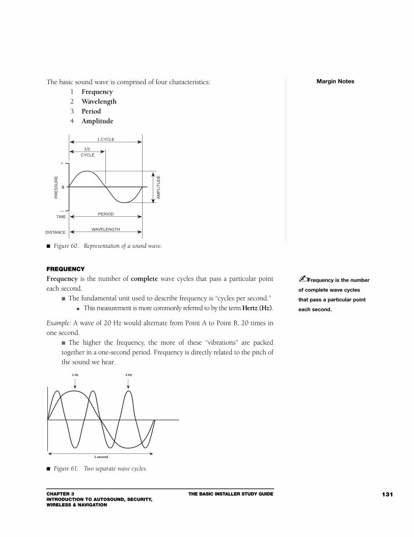
CHAPTER 3INTRODUCTION TO AUTOSOUND, SECURITY,WIRELESS & NAVIGATION
THE BASIC INSTALLER STUDY GUIDE 131
The basic sound wave is comprised of four characteristics:1 Frequency2 Wavelength3 Period4 Amplitude
FREQUENCY
Frequency is the number of complete wave cycles that pass a particular pointeach second.
The fundamental unit used to describe frequency is “cycles per second.” This measurement is more commonly referred to by the term Hertz (Hz).
Example: A wave of 20 Hz would alternate from Point A to Point B, 20 times inone second.
The higher the frequency, the more of these “vibrations” are packedtogether in a one-second period. Frequency is directly related to the pitch ofthe sound we hear.
Margin Notes
Frequency is the number
of complete wave cycles
that pass a particular point
each second.
WAVELENGTH
PERIOD
1 CYCLE
DISTANCE
TIME
PR
ES
SU
RE
—
0
+A
MP
LIT
UD
ECYCLE
1/2
Figure 60. Representation of a sound wave.
1 second
1 Hz 3 Hz
Figure 61. Two separate wave cycles.
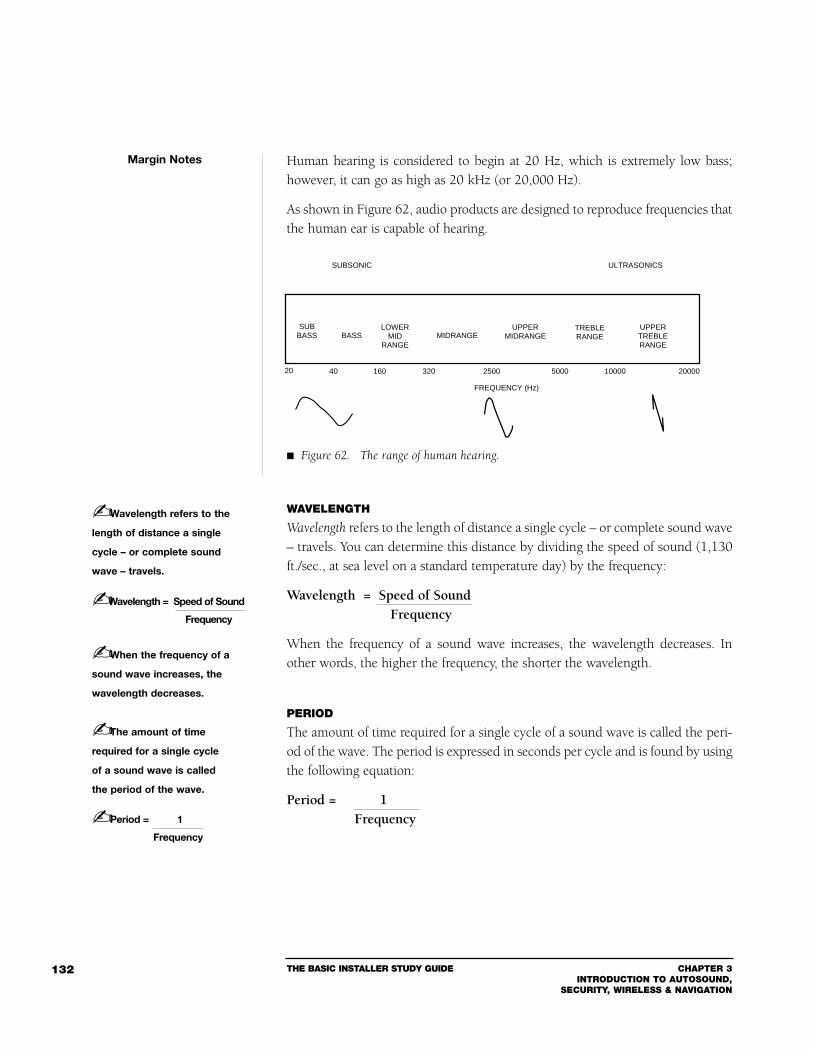
THE BASIC INSTALLER STUDY GUIDE CHAPTER 3INTRODUCTION TO AUTOSOUND,
SECURITY, WIRELESS & NAVIGATION
132
Human hearing is considered to begin at 20 Hz, which is extremely low bass;however, it can go as high as 20 kHz (or 20,000 Hz).
As shown in Figure 62, audio products are designed to reproduce frequencies thatthe human ear is capable of hearing.
WAVELENGTH
Wavelength refers to the length of distance a single cycle – or complete sound wave– travels. You can determine this distance by dividing the speed of sound (1,130ft./sec., at sea level on a standard temperature day) by the frequency:
Wavelength = Speed of SoundFrequency
When the frequency of a sound wave increases, the wavelength decreases. Inother words, the higher the frequency, the shorter the wavelength.
PERIOD
The amount of time required for a single cycle of a sound wave is called the peri-od of the wave. The period is expressed in seconds per cycle and is found by usingthe following equation:
Period = 1Frequency
Margin Notes
SUBSONIC ULTRASONICS
SUBBASS BASS
LOWERMID
RANGEMIDRANGE
UPPERMIDRANGE
UPPERTREBLERANGE
20 40 160 320 2500 5000 10000 20000
TREBLERANGE
FREQUENCY (Hz)
Figure 62. The range of human hearing.
Wavelength refers to the
length of distance a single
cycle – or complete sound
wave – travels.
Wavelength = Speed of Sound
Frequency
When the frequency of a
sound wave increases, the
wavelength decreases.
The amount of time
required for a single cycle
of a sound wave is called
the period of the wave.
Period = 1
Frequency
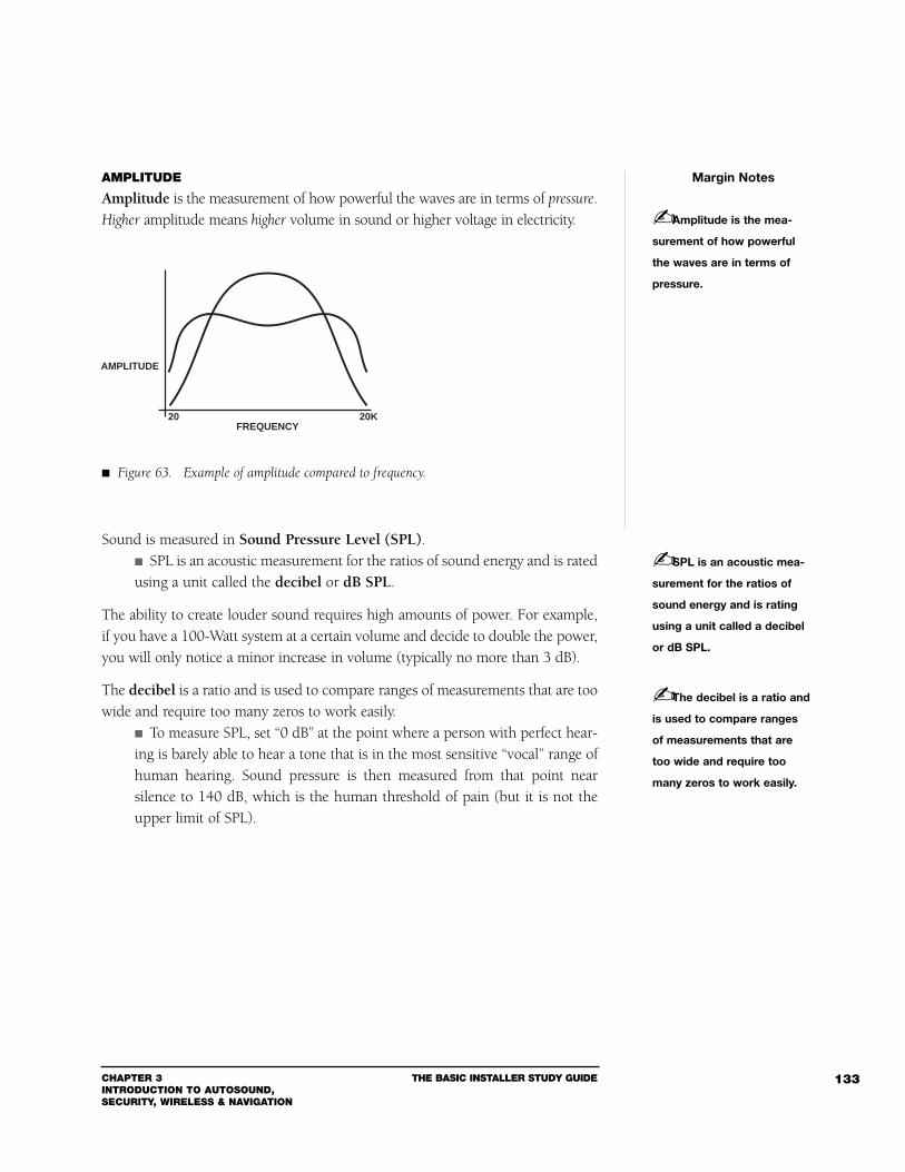
CHAPTER 3INTRODUCTION TO AUTOSOUND, SECURITY, WIRELESS & NAVIGATION
THE BASIC INSTALLER STUDY GUIDE 133
AMPLITUDE
Amplitude is the measurement of how powerful the waves are in terms of pressure.Higher amplitude means higher volume in sound or higher voltage in electricity.
Sound is measured in Sound Pressure Level (SPL). SPL is an acoustic measurement for the ratios of sound energy and is ratedusing a unit called the decibel or dB SPL.
The ability to create louder sound requires high amounts of power. For example,if you have a 100-Watt system at a certain volume and decide to double the power,you will only notice a minor increase in volume (typically no more than 3 dB).
The decibel is a ratio and is used to compare ranges of measurements that are toowide and require too many zeros to work easily.
To measure SPL, set “0 dB” at the point where a person with perfect hear-ing is barely able to hear a tone that is in the most sensitive “vocal” range ofhuman hearing. Sound pressure is then measured from that point nearsilence to 140 dB, which is the human threshold of pain (but it is not theupper limit of SPL).
Margin Notes
Amplitude is the mea-
surement of how powerful
the waves are in terms of
pressure.
FREQUENCY
AMPLITUDE
20 20K
Figure 63. Example of amplitude compared to frequency.
SPL is an acoustic mea-
surement for the ratios of
sound energy and is rating
using a unit called a decibel
or dB SPL.
The decibel is a ratio and
is used to compare ranges
of measurements that are
too wide and require too
many zeros to work easily.
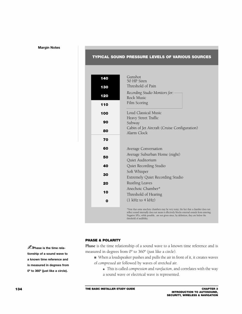
THE BASIC INSTALLER STUDY GUIDE CHAPTER 3INTRODUCTION TO AUTOSOUND,
SECURITY, WIRELESS & NAVIGATION
134
PHASE & POLARITY
Phase is the time relationship of a sound wave to a known time reference and ismeasured in degrees from 0º to 360º (just like a circle).
When a loudspeaker pushes and pulls the air in front of it, it creates wavesof compressed air followed by waves of stretched air.
This is called compression and rarefaction, and correlates with the waya sound wave or electrical wave is represented.
Margin Notes
Gunshot50 HP SirenThreshold of Pain
Recording Studio Monitors for:Rock MusicFilm Scoring
Loud Classical MusicHeavy Street TrafficSubwayCabin of Jet Aircraft (Cruise Configuration)Alarm Clock
Average ConversationAverage Suburban Home (night)Quiet AuditoriumQuiet Recording StudioSoft Whisper Extremely Quiet Recording StudioRustling LeavesAnechoic Chamber*Threshold of Hearing(1 kHz to 4 kHz)
*Note that some anechoic chambers may be very noisy; the fact that a chamber does notreflect sound internally does not mean it effectively blocks external sounds from entering.Negative SPLs, while possible, are not given since, by definition, they are below thethreshold of audibility.
TYPICAL SOUND PRESSURE LEVELS OF VARIOUS SOURCES
140
130
120
110
100
90
80
70
60
50
40
30
20
10
0
Phase is the time rela-
tionship of a sound wave to
a known time reference and
is measured in degrees from
0º to 360º (just like a circle).
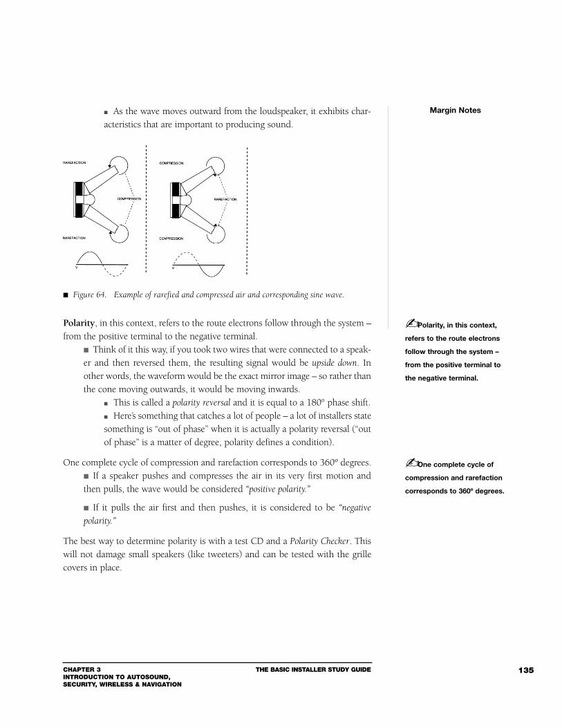
CHAPTER 3INTRODUCTION TO AUTOSOUND, SECURITY, WIRELESS & NAVIGATION
THE BASIC INSTALLER STUDY GUIDE 135
As the wave moves outward from the loudspeaker, it exhibits char-acteristics that are important to producing sound.
Polarity, in this context, refers to the route electrons follow through the system –from the positive terminal to the negative terminal.
Think of it this way, if you took two wires that were connected to a speak-er and then reversed them, the resulting signal would be upside down. Inother words, the waveform would be the exact mirror image – so rather thanthe cone moving outwards, it would be moving inwards.
This is called a polarity reversal and it is equal to a 180° phase shift. Here’s something that catches a lot of people – a lot of installers statesomething is “out of phase” when it is actually a polarity reversal (“outof phase” is a matter of degree, polarity defines a condition).
One complete cycle of compression and rarefaction corresponds to 360º degrees. If a speaker pushes and compresses the air in its very first motion andthen pulls, the wave would be considered “positive polarity.”
If it pulls the air first and then pushes, it is considered to be “negative
polarity.”
The best way to determine polarity is with a test CD and a Polarity Checker. Thiswill not damage small speakers (like tweeters) and can be tested with the grillecovers in place.
Margin Notes
Figure 64. Example of rarefied and compressed air and corresponding sine wave.
Polarity, in this context,
refers to the route electrons
follow through the system –
from the positive terminal to
the negative terminal.
One complete cycle of
compression and rarefaction
corresponds to 360º degrees.
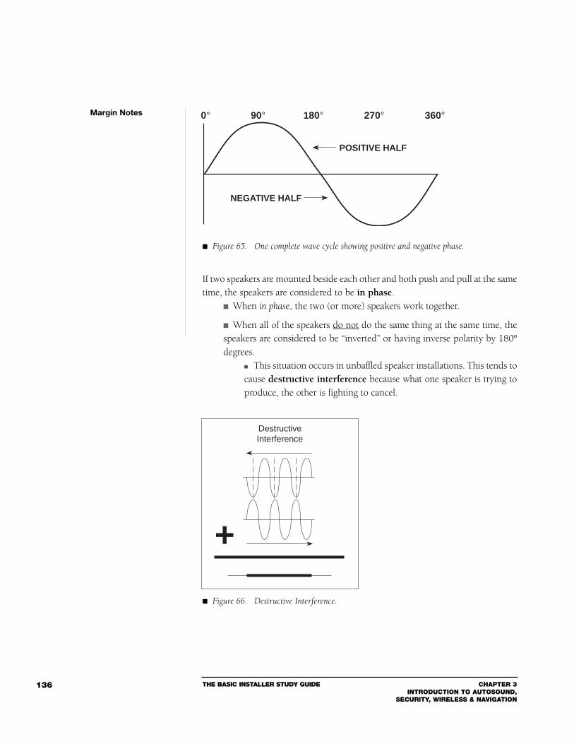
THE BASIC INSTALLER STUDY GUIDE CHAPTER 3INTRODUCTION TO AUTOSOUND,
SECURITY, WIRELESS & NAVIGATION
136
If two speakers are mounted beside each other and both push and pull at the sametime, the speakers are considered to be in phase.
When in phase, the two (or more) speakers work together.
When all of the speakers do not do the same thing at the same time, thespeakers are considered to be “inverted” or having inverse polarity by 180ºdegrees.
This situation occurs in unbaffled speaker installations. This tends tocause destructive interference because what one speaker is trying toproduce, the other is fighting to cancel.
Margin Notes 0° 90° 180° 270° 360°
POSITIVE HALF
NEGATIVE HALF
Figure 65. One complete wave cycle showing positive and negative phase.
Destructive Interference
+
Figure 66. Destructive Interference.
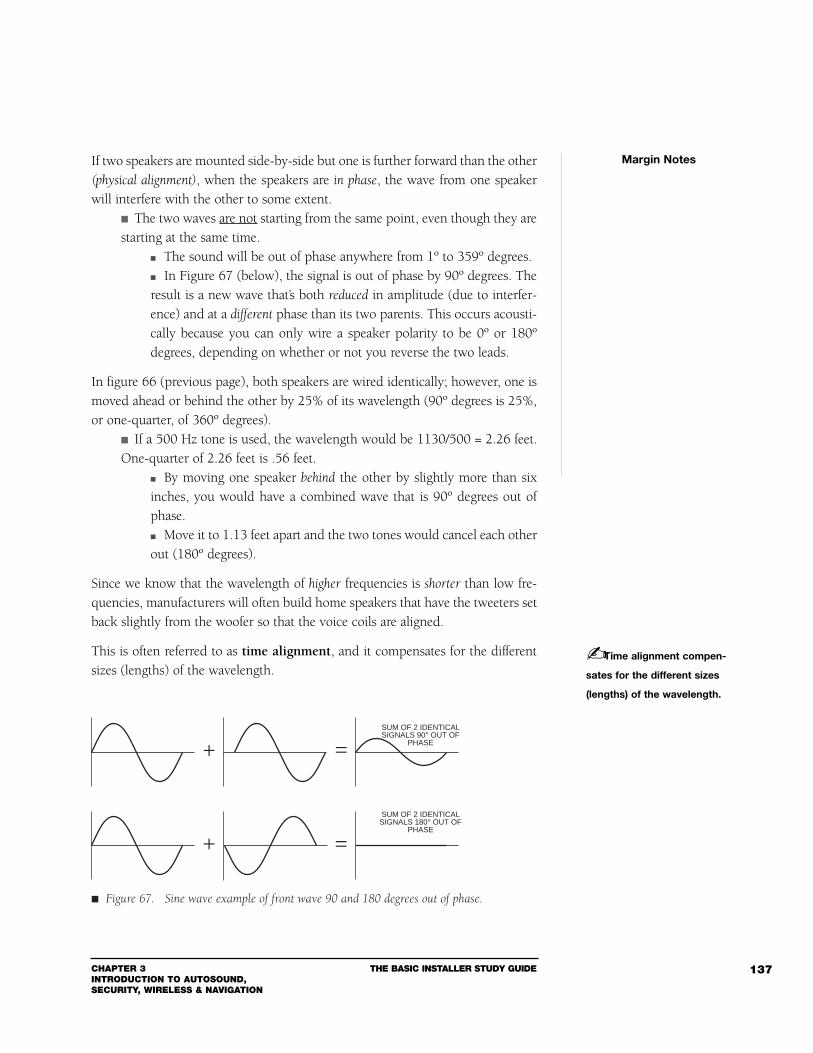
CHAPTER 3INTRODUCTION TO AUTOSOUND, SECURITY, WIRELESS & NAVIGATION
THE BASIC INSTALLER STUDY GUIDE 137
If two speakers are mounted side-by-side but one is further forward than the other(physical alignment), when the speakers are in phase, the wave from one speakerwill interfere with the other to some extent.
The two waves are not starting from the same point, even though they arestarting at the same time.
The sound will be out of phase anywhere from 1º to 359º degrees. In Figure 67 (below), the signal is out of phase by 90º degrees. Theresult is a new wave that’s both reduced in amplitude (due to interfer-ence) and at a different phase than its two parents. This occurs acousti-cally because you can only wire a speaker polarity to be 0º or 180ºdegrees, depending on whether or not you reverse the two leads.
In figure 66 (previous page), both speakers are wired identically; however, one ismoved ahead or behind the other by 25% of its wavelength (90º degrees is 25%,or one-quarter, of 360º degrees).
If a 500 Hz tone is used, the wavelength would be 1130/500 = 2.26 feet.One-quarter of 2.26 feet is .56 feet.
By moving one speaker behind the other by slightly more than sixinches, you would have a combined wave that is 90º degrees out ofphase. Move it to 1.13 feet apart and the two tones would cancel each otherout (180º degrees).
Since we know that the wavelength of higher frequencies is shorter than low fre-quencies, manufacturers will often build home speakers that have the tweeters setback slightly from the woofer so that the voice coils are aligned.
This is often referred to as time alignment, and it compensates for the differentsizes (lengths) of the wavelength.
Margin Notes
Time alignment compen-
sates for the different sizes
(lengths) of the wavelength.
+
+ =
=SUM OF 2 IDENTICALSIGNALS 90° OUT OF
PHASE
SUM OF 2 IDENTICALSIGNALS 180° OUT OF
PHASE
Figure 67. Sine wave example of front wave 90 and 180 degrees out of phase.
THE BASIC INSTALLER STUDY GUIDE CHAPTER 3INTRODUCTION TO AUTOSOUND,
SECURITY, WIRELESS & NAVIGATION
138
Here’s how you can tell when a four-speaker, full-range system is out of phase (orhaving most commonly an inverted polarity) by just listening:
1 Balance the system left to right. 2 If the bass is strong on one channel and weak on the other, and themidrange and highs do not sound distinct, go to the amp (or head unit'sinternal amp) and reverse the speaker lead on one side only. 3 Listen to the system again. 4 Balance left to right to see if the distance or “muddiness” has clearedup and listen to see if the bass seems tighter. If so, the speakers could beout of phase or have an inverted polarity.
Depending on you situation you could have a problem that is corrected simply byreversing polarity electrically (this is a simple fix). If the problem is phase, youcould also have to change speaker position or location.
RESONANCE
All objects have a natural tendency to vibrate at certain frequencies. A crystal wineglass, when tapped, will vibrate air to produce a tone some-where between 2 kHz and 6 kHz.
The smaller the glass, the higher the pitch of the tone.
If you were to play a tone at the same frequency that the glass produces, the glasswould begin to vibrate on its own. This is known as sympathetic vibration andis caused by the natural resonance of the object.
A bass drum will respond to frequencies around 30 Hz to 130 Hz. Playing a tonein this range, and at a high enough volume, will cause the bass drum to vibrateseverely.
FREQUENCY RESPONSE
Frequency response is one of the most important sonic measurements for deter-mining quality. Frequency response is the relationship between each individualfrequency and its amplitude (this includes refraction and absorption, or con-structive and destructive interference). To have a flat response, a system mustreproduce all frequencies in the human hearing bandwidth (20 – 20k Hz) withequal amplitude.
Margin Notes
Frequency response is
the relationship between
each individual frequency
and its amplitude.
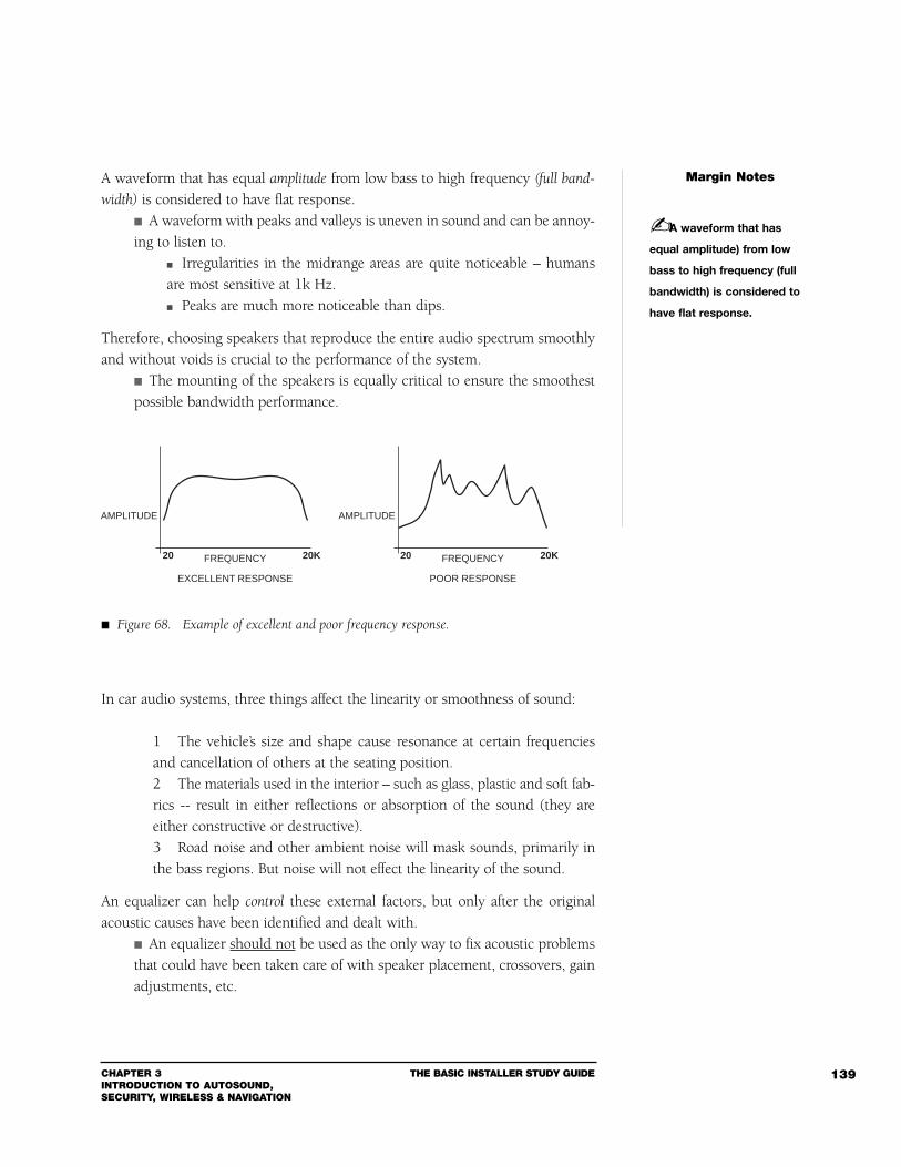
CHAPTER 3INTRODUCTION TO AUTOSOUND, SECURITY, WIRELESS & NAVIGATION
THE BASIC INSTALLER STUDY GUIDE 139
A waveform that has equal amplitude from low bass to high frequency (full band-
width) is considered to have flat response. A waveform with peaks and valleys is uneven in sound and can be annoy-ing to listen to.
Irregularities in the midrange areas are quite noticeable – humansare most sensitive at 1k Hz. Peaks are much more noticeable than dips.
Therefore, choosing speakers that reproduce the entire audio spectrum smoothlyand without voids is crucial to the performance of the system.
The mounting of the speakers is equally critical to ensure the smoothestpossible bandwidth performance.
In car audio systems, three things affect the linearity or smoothness of sound:
1 The vehicle’s size and shape cause resonance at certain frequenciesand cancellation of others at the seating position.2 The materials used in the interior – such as glass, plastic and soft fab-rics -- result in either reflections or absorption of the sound (they areeither constructive or destructive).3 Road noise and other ambient noise will mask sounds, primarily inthe bass regions. But noise will not effect the linearity of the sound.
An equalizer can help control these external factors, but only after the originalacoustic causes have been identified and dealt with.
An equalizer should not be used as the only way to fix acoustic problemsthat could have been taken care of with speaker placement, crossovers, gainadjustments, etc.
Margin Notes
A waveform that has
equal amplitude) from low
bass to high frequency (full
bandwidth) is considered to
have flat response.
FREQUENCY
POOR RESPONSE
AMPLITUDE
20 20KFREQUENCY
EXCELLENT RESPONSE
AMPLITUDE
20 20K
Figure 68. Example of excellent and poor frequency response.
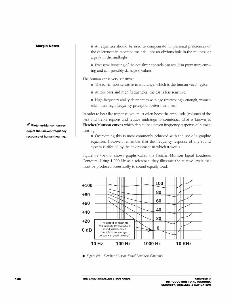
THE BASIC INSTALLER STUDY GUIDE CHAPTER 3INTRODUCTION TO AUTOSOUND,
SECURITY, WIRELESS & NAVIGATION
140
An equalizer should be used to compensate for personal preferences orthe differences in recorded material, not an obvious hole in the midbass ora peak in the midhighs.
Excessive boosting of the equalizer controls can result in premature curv-ing and can possibly damage speakers.
The human ear is very sensitive: The ear is most sensitive to midrange, which is the human vocal region.
At low bass and high frequencies, the ear is less sensitive.
High frequency ability deteriorates with age (interestingly enough, womenretain their high frequency perception better than men.)
In order to hear flat response, you must often boost the amplitude (volume) of thebass and treble regions and reduce midrange to counteract what is known asFletcher-Munson curves which depict the uneven frequency response of humanhearing.
Overcoming this is most commonly achieved with the use of a graphicequalizer. However, remember that the frequency response of any soundsystem is affected by the environment in which it works.
Figure 69 (below) shows graphs called the Fletcher-Munson Equal LoudnessContours. Using 1,000 Hz as a reference, they illustrate the relative levels thatmust be produced acoustically to sound equally loud.
Margin Notes
Fletcher-Munson curves
depict the uneven frequency
response of human hearing.
10 Hz 100 Hz 1000 Hz 10 KHz
+100
+80
+60
+40
+20
0 dB
100
80
60
40
20
0Threshold of Hearing
“An intensity level at whichsound just becomes
audible in an averageperson with good hearing.”
Figure 69. Fletcher-Munson Equal Loudness Contours.
CHAPTER 3INTRODUCTION TO AUTOSOUND, SECURITY, WIRELESS & NAVIGATION
THE BASIC INSTALLER STUDY GUIDE 141
OCTAVES AND HARMONICS
An octave is a musical interval between two tones formed when the ratio betweenthe frequencies of the tone is 2:1 (i.e., a doubling or halving of a frequency).
Unless it is an electronically produced pure tone, a musical note will haveovertones and harmonics.
A musical note has octaves that double the previous octave. A note at a frequency of 440 Hz has octaves at 880 Hz, 1760 Hz,3520 Hz, etc. Each octave has eight full tones above and below another given tone.
Octaves also relate to the vocal range of a singer or musical instrument, asin soprano, alto, tenor, basso, etc.
The fundamental frequency created by most musical instruments – with theexception of synthesizers and pipe organs – is limited to about 8 kHz.
A harmonic is a weaker overtone of the original note (the fundamental frequency)and is responsible for the character of the note.
When a musical note with a complex waveform has a distinct pitch (as opposed tojust plain noise), that waveform can be created by combining a set of precisely relat-ed sine waves. These sine waves are called harmonics. We recognize voices on the tele-phone because people sound different due to the harmonic content of their voices.
Harmonics occur at frequencies that are multiples of the original note. A note at a frequency of 440 Hz may or may not have harmonics at880 Hz, 1320 Hz, 1760 Hz, 2200 Hz, etc., and sub-harmonics at 220Hz, 110 Hz, 55 Hz, etc.
If two instruments have exactly the same harmonic structure and strength, theywill sound identical. If only one harmonic is absent or significantly altered, a dif-ference would be discernible to those with excellent hearing.
Speaker basics: A basic speaker has a narrow frequency range, depending on the size ofthe speaker cone. Large speaker cones naturally produce bass, while small cones producehigher frequencies.
Since a single speaker cone cannot cover all of the frequencies in the audible spec-trum, manufacturers combine a larger bass cone with a small treble driver – ortweeter – to more effectively cover the entire spectrum. The overall intention is toimprove the frequency response of the system to give you a flat response andimprove the sound quality.
Margin Notes
An octave is a musical
interval between two tones
formed when the ratio
between the frequencies
of the tone is 2:1.
A harmonic is a weaker
overtone or undertone of the
original note (the fundamen-
tal frequency) and is respon-
sible for the character of the
note.

THE BASIC INSTALLER STUDY GUIDE CHAPTER 3INTRODUCTION TO AUTOSOUND,
SECURITY, WIRELESS & NAVIGATION
142
Special cabinet-style speakers have been designed to fill in the lower bass region,these regions are difficult for virtually any vehicle to support.
Subwoofer systems are intended to accurately reproduce the sub-bassregion.
SIGNAL TO NOISE
Signal to noise (s/n) is a ratio that indicates how much audio signal there is inrelation to noise, under specific conditions.
A high s/n ratio is always preferable to a low s/n. This ratio of audio output level to the level of noise is expressed indecibels (dB). The s/n ratio usually begins at the noise level, whether high or low,and goes to some arbitrary nominal level.
A musical note can be masked in a number of ways. Acoustically, the ambientnoise that occurs in the vehicle – as well as the road, wind, and traffic – will com-bine to mask the quieter musical passages. This is referred to as the “noise floor,”
and is concentrated mostly in the bass regions. Many of today’s cars -- particularly the luxury cars -- do an excellent jobof lowering the noise floor by insulating the outside noises.
Electrically, the circuit noise present in electronic products will mask the very low-level signals that try to pass. The design of the product generally dictates hownoisy it will be.
When parts of lower grade (more economical) are incorporated into a design,they will contribute to the thermal noise that infects the musical signal.
Quiet passages in the music will be covered by hiss.
Margin Notes
Signal to noise (s/n) is
a ratio that indicates how
much audio signal there
is in relation to noise,
under specific conditions.
HARMONICS
OCTAVESFUNDAMENTALS
SUBHARMONIC
220 HZ 440 HZ 880 HZ 1760 HZ 3520 HZ
Figure 70. Examples of octaves, harmonics and their fundamental tone.
A high s/n ratio is always
preferable to a low s/n.
CHAPTER 3INTRODUCTION TO AUTOSOUND, SECURITY, WIRELESS & NAVIGATION
THE BASIC INSTALLER STUDY GUIDE 143
DYNAMIC RANGE OF A MUSIC RECORDING
Dynamic range is the range of volume, in DeciBels from the softest to the loudest,produced by a source of sounds. The reference is usually a musical selection, orprogram signal being played.
A program is a structured, narrow band signal, while noise is a random,wideband signal.
Rock and heavy metal music have a low dynamic range since the dif-ference between the quiet lead guitar solo of 100 dB SPL and a fullcrescendo of 130 dB SPL is only 30 dB. Classical music can have a quiet flute solo of 60 dB SPL, followed bya crescendo of 110 dB SPL that results in a dynamic range of 50 dB.
Even though the rock selection is louder overall, the classical selection has fargreater dynamic range.
HEADROOM
Headroom is one of those terms that are quite common in audio jargon. But askanyone to define headroom, and they’re at a loss. For once and for all, here is adefinition: In an audio device, headroom refers to the difference in levels betweenthe highest level in a given signal and the maximum level that the unit can han-dle without distortion.
Obviously, more headroom is desirable. The music can have short peaks that are much higher in level thanthe average signal level. For example, a musical crescendo consumes alot of power and can quickly push a system to its limits. These short peaks are not registered by most audio level readingdevices and if the musical demand is higher than the system’s ability totrack it, the result is severe distortion (clipping) and probable damage.
Think of headroom this way: Imagine you’re jumping on a trampoline in a room with a low ceiling –the consequences could be painful.
If you could raise the ceiling (add more “headroom”), then thechance of hitting your head on the ceiling would be lessened.
In terms of a concert, the average sound level (100-110 dB SPL) is the nominalprogram level.
The difference between the highest (peak) levels and the nominal level isthe headroom.
The classical music in the last section has more headroom than therock concert.
Margin Notes
Dynamic range is the
range of volume, in DeciBels
from the softest to the loud-
est, produced by a source of
sounds.
Headroom in an audio
device refers to the differ-
ence in levels between the
highest level in a given signal
and the maximum level that
the unit can handle without
distortion.
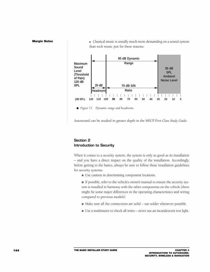
THE BASIC INSTALLER STUDY GUIDE CHAPTER 3INTRODUCTION TO AUTOSOUND,
SECURITY, WIRELESS & NAVIGATION
144
Classical music is usually much more demanding on a sound systemthan rock music just for these reasons.
Autosound can be studied in greater depth in the MECP First Class Study Guide.
Section 2Introduction to Security
When it comes to a security system, the system is only as good as its installation– and you have a direct impact on the quality of the installation. Accordingly,before getting to the basics, always be sure to follow these installation guidelinesfor security systems:
Use caution in determining component locations.
If possible, refer to the vehicle’s owner’s manual to ensure the security sys-tem is installed in harmony with the other components on the vehicle (theremight be some major differences in the operating characteristics and wiringcompared to previous models).
Make sure all the connections are solid – use solder whenever possible.
Use a multimeter to check all wires – never use an incandescent test light.
Margin Notes
Figure 71. Dynamic range and headroom.
30 dBSPL
AmbientNoise Level
90 dB DynamicRange
70 dB S/NRatio
20 dB
Headroom
120 30
MaximumSoundLevel(Thresholdof Pain)120 dBSPL
(dB SPL) 020 1040506070809030100110
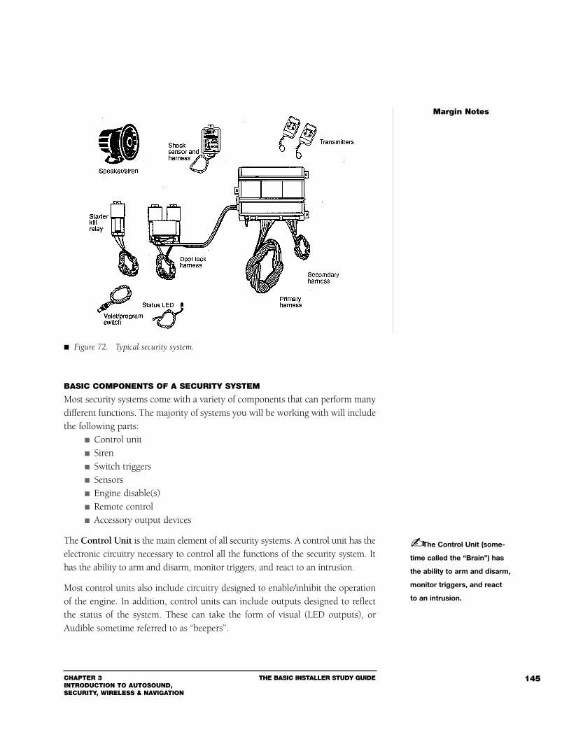
CHAPTER 3INTRODUCTION TO AUTOSOUND, SECURITY, WIRELESS & NAVIGATION
THE BASIC INSTALLER STUDY GUIDE 145
BASIC COMPONENTS OF A SECURITY SYSTEM
Most security systems come with a variety of components that can perform manydifferent functions. The majority of systems you will be working with will includethe following parts:
Control unit Siren Switch triggers Sensors Engine disable(s) Remote control Accessory output devices
The Control Unit is the main element of all security systems. A control unit has theelectronic circuitry necessary to control all the functions of the security system. Ithas the ability to arm and disarm, monitor triggers, and react to an intrusion.
Most control units also include circuitry designed to enable/inhibit the operationof the engine. In addition, control units can include outputs designed to reflectthe status of the system. These can take the form of visual (LED outputs), orAudible sometime referred to as “beepers”.
Margin Notes
The Control Unit (some-
time called the “Brain”) has
the ability to arm and disarm,
monitor triggers, and react
to an intrusion.
Figure 72. Typical security system.
THE BASIC INSTALLER STUDY GUIDE CHAPTER 3INTRODUCTION TO AUTOSOUND,
SECURITY, WIRELESS & NAVIGATION
146
Since control units are the central governing element, they are often calledthe “brain” of the security system.
Control units chirp sirens, blink parking lights, and sound alarms inresponse to commands or intrusions.
More sophisticated systems include multiple trigger inputs that enableyou to connect a different area of the vehicle to a different trigger input.
This allows the installer to divide up the vehicle into separate“zones” for the purpose of easier system management and trou-bleshooting. Some systems with multiple trigger inputs include a method to indi-vidually monitor and verify each trigger, sometimes called “diagnostics.” This aids the installer or consumer in detecting and isolating a trig-ger-related problem.
SIRENS
The electronic siren is the most common form of sounding device found as stan-dard equipment in today's automotive security systems. Usually, this device is aself-contained unit consisting of three basic sections or stages:
1 The oscillator or tone generator stage2 The amplifier stage3 The speaker or output stage
The typical electronic siren can, therefore, produce its warning sound simply bybeing connected to the proper power source.
Electronic sirens come in all shapes and sizes, but the most common is the bell orhorn shape.
The horn shape contributes to overall volume as well as pitch.
The outer casings of some sirens are composed of metal, but the greatmajorities are made from various types of high temperature plastic.
SWITCH TRIGGERS
Switch triggers come in many different forms. The most common is the simplespring-loaded pinswitch. Others include the roller push-button type, the mag-netic reed switch type, metal pressure strip type, and the mercury tilt type. Eachof these types has advantages and disadvantages.
There are several types of triggering devices, we will cover just a few of the mostcommon ones:
Margin Notes
CHAPTER 3INTRODUCTION TO AUTOSOUND, SECURITY, WIRELESS & NAVIGATION
THE BASIC INSTALLER STUDY GUIDE 147
Spring-Loaded Pinswitch - This type of switch usually consists of aspring-loaded plastic plunger set within a cylindrical metal housing that isthreaded at one end.
Roller push-button - The roller push-button type is very similar to thespring-loaded pinswitch except that instead of using a straight linearplunger, it uses a ball or “roller” to push against an internal plunger and setof contacts.
This feature makes it ideal for applications where a normal spring-loaded pinswitch would shear off, such as uneven surfaces and slidingpanels. This switch is typically used to protect truck tailgates, drawers oftool boxes, hoods, and other compartments that slide open.
Magnetic Reed Switch - The magnetic reed switch (also called a magnetic
proximity switch) uses magnetic force to cause a set of contacts to connect.
This switch basically comes in two parts: a switch and a magnet. The switch contains a set of magnetic “reeds” or two thin flexible sliversof metal, each with a contact at one end.
These reeds are enclosed inside a glass tube, insulated from eachother and attached to a stationary point at one end. Each reed is connected to a wire, and each wire is run outside theglass tube. The whole switch assembly is typically placed inside a rectangularplastic case.
SENSORS
Motion Sensors - A motion sensor is designed to detect motion – but what kindof motion? The main purpose behind a typical motion sensor is to detect thedegree of motion a vehicle might undergo if it were being “jacked up” or if anattempt was made to “tow” the vehicle.
These forms of “motion” usually consist of: Gentle and nearly vertical up-and-down motions (i.e., those pro-duced by a ratcheting jack), or… A gradual change in the vehicle’s angle relative to the plane on whichit is parked (i.e., the change in angle that occurs when the front or backof the vehicle is lifted for towing).
Shock and Impact Sensors - Shock and impact sensors are probably one of themost common sensors in use in vehicle security systems today. They are typicallydesigned to detect the various degrees of impact that might be applied to a vehi-
Margin Notes
Magnetic reed switches
come in two basic electrical
forms: Normally Open and
Normally Closed.
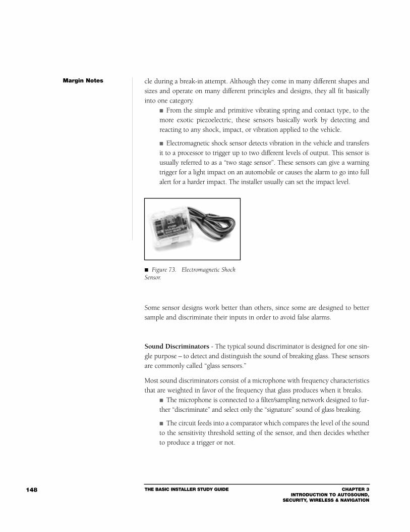
THE BASIC INSTALLER STUDY GUIDE CHAPTER 3INTRODUCTION TO AUTOSOUND,
SECURITY, WIRELESS & NAVIGATION
148
cle during a break-in attempt. Although they come in many different shapes andsizes and operate on many different principles and designs, they all fit basicallyinto one category.
From the simple and primitive vibrating spring and contact type, to themore exotic piezoelectric, these sensors basically work by detecting andreacting to any shock, impact, or vibration applied to the vehicle.
Electromagnetic shock sensor detects vibration in the vehicle and transfersit to a processor to trigger up to two different levels of output. This sensor isusually referred to as a “two stage sensor”. These sensors can give a warningtrigger for a light impact on an automobile or causes the alarm to go into fullalert for a harder impact. The installer usually can set the impact level.
Some sensor designs work better than others, since some are designed to bettersample and discriminate their inputs in order to avoid false alarms.
Sound Discriminators - The typical sound discriminator is designed for one sin-gle purpose – to detect and distinguish the sound of breaking glass. These sensorsare commonly called “glass sensors.”
Most sound discriminators consist of a microphone with frequency characteristicsthat are weighted in favor of the frequency that glass produces when it breaks.
The microphone is connected to a filter/sampling network designed to fur-ther “discriminate” and select only the “signature” sound of glass breaking.
The circuit feeds into a comparator which compares the level of the soundto the sensitivity threshold setting of the sensor, and then decides whetherto produce a trigger or not.
Margin Notes
Figure 73. Electromagnetic ShockSensor.
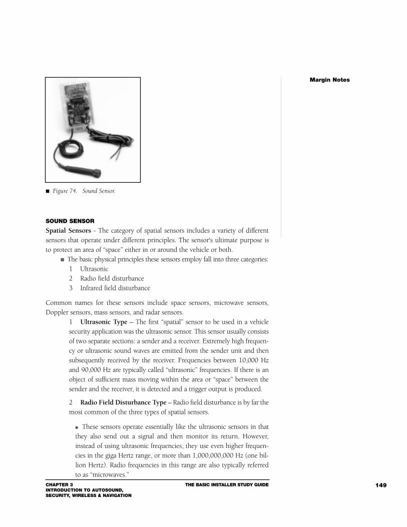
CHAPTER 3INTRODUCTION TO AUTOSOUND, SECURITY, WIRELESS & NAVIGATION
THE BASIC INSTALLER STUDY GUIDE 149
SOUND SENSOR
Spatial Sensors - The category of spatial sensors includes a variety of differentsensors that operate under different principles. The sensor's ultimate purpose isto protect an area of “space” either in or around the vehicle or both.
The basic physical principles these sensors employ fall into three categories:1 Ultrasonic2 Radio field disturbance3 Infrared field disturbance
Common names for these sensors include space sensors, microwave sensors,Doppler sensors, mass sensors, and radar sensors.
1 Ultrasonic Type – The first “spatial” sensor to be used in a vehiclesecurity application was the ultrasonic sensor. This sensor usually consistsof two separate sections: a sender and a receiver. Extremely high frequen-cy or ultrasonic sound waves are emitted from the sender unit and thensubsequently received by the receiver. Frequencies between 10,000 Hzand 90,000 Hz are typically called “ultrasonic” frequencies. If there is anobject of sufficient mass moving within the area or “space” between thesender and the receiver, it is detected and a trigger output is produced.
2 Radio Field Disturbance Type – Radio field disturbance is by far themost common of the three types of spatial sensors.
These sensors operate essentially like the ultrasonic sensors in thatthey also send out a signal and then monitor its return. However,instead of using ultrasonic frequencies, they use even higher frequen-cies in the giga Hertz range, or more than 1,000,000,000 Hz (one bil-lion Hertz). Radio frequencies in this range are also typically referredto as “microwaves.”
Margin Notes
Figure 74. Sound Sensor.
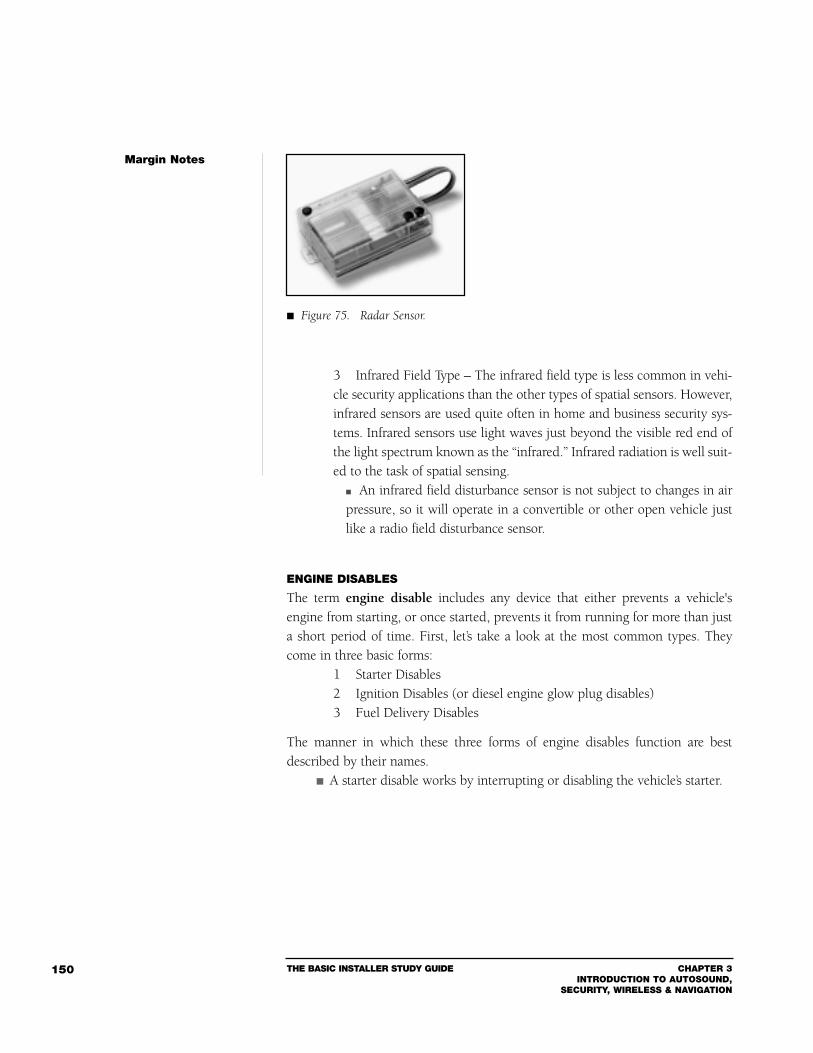
THE BASIC INSTALLER STUDY GUIDE CHAPTER 3INTRODUCTION TO AUTOSOUND,
SECURITY, WIRELESS & NAVIGATION
150
3 Infrared Field Type – The infrared field type is less common in vehi-cle security applications than the other types of spatial sensors. However,infrared sensors are used quite often in home and business security sys-tems. Infrared sensors use light waves just beyond the visible red end ofthe light spectrum known as the “infrared.” Infrared radiation is well suit-ed to the task of spatial sensing.
An infrared field disturbance sensor is not subject to changes in airpressure, so it will operate in a convertible or other open vehicle justlike a radio field disturbance sensor.
ENGINE DISABLES
The term engine disable includes any device that either prevents a vehicle'sengine from starting, or once started, prevents it from running for more than justa short period of time. First, let’s take a look at the most common types. Theycome in three basic forms:
1 Starter Disables2 Ignition Disables (or diesel engine glow plug disables)3 Fuel Delivery Disables
The manner in which these three forms of engine disables function are bestdescribed by their names.
A starter disable works by interrupting or disabling the vehicle’s starter.
Margin Notes
Figure 75. Radar Sensor.
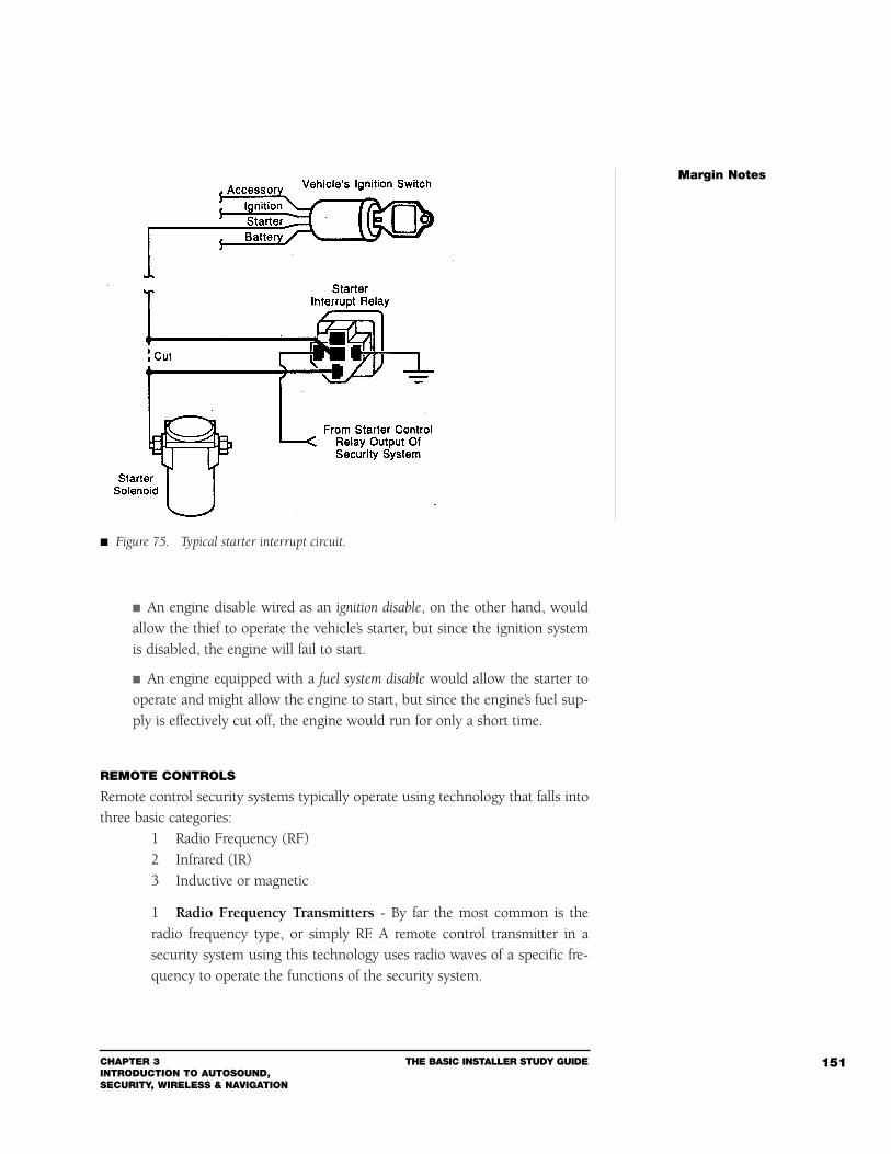
CHAPTER 3INTRODUCTION TO AUTOSOUND, SECURITY, WIRELESS & NAVIGATION
THE BASIC INSTALLER STUDY GUIDE 151
An engine disable wired as an ignition disable, on the other hand, wouldallow the thief to operate the vehicle’s starter, but since the ignition systemis disabled, the engine will fail to start.
An engine equipped with a fuel system disable would allow the starter tooperate and might allow the engine to start, but since the engine’s fuel sup-ply is effectively cut off, the engine would run for only a short time.
REMOTE CONTROLS
Remote control security systems typically operate using technology that falls intothree basic categories:
1 Radio Frequency (RF)2 Infrared (IR)3 Inductive or magnetic
1 Radio Frequency Transmitters - By far the most common is theradio frequency type, or simply RF. A remote control transmitter in asecurity system using this technology uses radio waves of a specific fre-quency to operate the functions of the security system.
Margin Notes
Figure 75. Typical starter interrupt circuit.
THE BASIC INSTALLER STUDY GUIDE CHAPTER 3INTRODUCTION TO AUTOSOUND,
SECURITY, WIRELESS & NAVIGATION
152
The frequencies used by most brands of RF remote security systemstypically fall somewhere between 300 to 470 MHz.
This frequency band is also used by remote controls for some auto-matic garage door openers as well as some remote engine start devices.
2 Infrared - The second form of remote transmitter in use today is theinfrared. Unlike the radio frequency type transmitter, the infrared mustbe used within line of sight of the vehicle. This is due to the fact that theinfrared radiation emitted by these units travels only in one narrowstraight line.
3 Inductive/Magnetic - The third form of remote transmitter is actual-ly not a transmitter in the usual sense at all. These are typically referredto as the inductive or magnetic type.
Instead of “transmitting” a signal, these units use the electrical prop-erty of inductance to arm and disarm a security system. This is accomplished by passing the remote within just a few inches ofa special pickup usually located on one of the glass areas of the vehicle. The “range” of these units is typically just a few inches.
ACCESSORY OUTPUT DEVICES
Accessory output devices incorporate circuits designed to control such things aspower door locks, power windows, power trunk/hatch releases, and garagedoor/gate operation. These devices utilize basic building block components fre-quently used by installers such as relays, diodes, and timers.
Relays - A relay is nothing more than a switch with contacts that are controlledby the magnetic field from an electromagnetic coil.
Relays – like switches – are classified by the way their contacts arearranged.
A relay may be designated a SPST (Single Pole Single Throw), or aSPDT (Single Pole Double Throw), or one of many other configurations. Due to these various contact configurations, a relay may be usedeither to “make” a connection or “break” a connection, depending onhow it is wired.
Diodes - Another commonly used device may not be considered a “device” at all.We’re referring to the simple semiconductor component – the diode. Diodes, likerelays, can help solve a vast number of installation challenges.
Margin Notes
A relay is nothing more
than a switch with contacts
that are controlled by the
magnetic field from an
electromagnetic coil.
CHAPTER 3INTRODUCTION TO AUTOSOUND, SECURITY, WIRELESS & NAVIGATION
THE BASIC INSTALLER STUDY GUIDE 153
A diode is nothing more than a one-way current valve. Voltage will flow througha diode in one direction only; this property can be used to allow circuits to remainisolated from each other and yet be connected to a common point as well.
Diodes can be used to isolate or connect circuits of either power or ground polar-ity, depending upon the direction in which the diode is installed. Just remember,a diode will block current flow in one direction, but allow current to flow in theopposite direction. A less accurate but more understandable explanation of this“one-way” action would be to say that when a diode is installed in a particulardirection, “power” will flow in one direction, but “ground” will not flow in thesame direction. In addition, the same diode will not allow “power” to flow in theopposite direction, but it will allow “ground” to flow in the opposite direction.
Universal Timers - A “pulse” or universal timer can convert a momentary dura-tion pulse from a security system or other source into a longer or shorter durationsignal to perform a variety of different tasks.
A timer might be used to create an interface between a remote securitysystem and the vehicle’s headlights. This would provide the driver of thevehicle with a lighted pathway for a period of time long enough to allowthem to walk with a greater degree of personal security.
TELEMATIC SYSTEMS
Telematic systems have all of the benefits of a tracking system, but does not needa full-fledged navigation system for their operation.
Telematics involve the creation and development of IntelligentTransportation Systems (ITS) to track navigation, traffic volume, and safetyof private and commercial vehicles on roads and highways.
Many commercial bus and trucking companies use these systems.
A telematic system receives longitude and latitude information from GPS satellitesvia a GPS antenna that’s concealed in the vehicle. The system then uses an embed-ded cellular phone connected to a wireless network to transmit vehicle status andposition information to a response center.
The driver can communicate with the response center by pressing a com-munications button.
Once connected to the response center, they can “see” the locationof the vehicle – longitude, latitude, speed and heading.
Margin Notes
A diode is nothing more
than a one-way current valve.
A "pulse" or universal
timer can convert a momen-
tary duration pulse from a
security system or other
source into a longer or short-
er duration signal to perform
a variety of different tasks.
THE BASIC INSTALLER STUDY GUIDE CHAPTER 3INTRODUCTION TO AUTOSOUND,
SECURITY, WIRELESS & NAVIGATION
154
The response center can provide a wide array of services: Dispatch roadside assistance. If the driver is lost, they can provide turn-by-turn directions. If the keys are locked in the car, the driver can call the
response center and have the doors unlocked. Some also offer a full range of concierge services, including
making reservations (for airlines, hotels, restaurants, etc.) purchasing tickets or flowers, etc.
Most systems include a panic button for emergency situations Thanks to the GPS capabilities, the response center can track a stolenvehicle.
They can dispatch help in the case of an emergency. The client can keep an in-depth, confidential medical history on-filewith the response center. Once the panic button is pushed, the response center then “calls” thevehicle to check on the driver. During a car jacking, when instructed by the police, the responsecenter can cut off the ignition and unlock the doors, stopping the vehi-cle and providing access to the occupants.
If the battery level drops or goes dead, the response center can alert the driver.
Some systems include airbag deployment notification – if the vehicle is inan accident in which the airbags deploy, the system automatically contactsthe response center.
BASIC INSTALLATION TIPS
The first installation rule to remember is that the ultimate success of any secu-rity system is directly related to the quality of its installation.
Putting this into perspective, if a pair of car speakers were wired “out of phase,”the problem could probably go unnoticed by the majority of your customers. Thisimproperly installed system may be just an annoyance, nothing more serious. Itmay not even impact the reputation of your company. However, an improperlyinstalled security system might awaken your customer and surrounding neigh-bors at 2:00 a.m. with false alarms. An improperly installed system may causeelectrical damage to factory wiring or fail to protect the vehicle.
The customer is placing a great deal of trust in you and your installation quality.If a vehicle is damaged or stolen as a result of faulty installation, the owner willfeel betrayed by the installer and the shop itself. Not only will you have lost onecustomer, but those future referrals that a “satisfied” customer will provide.
Margin Notes
CHAPTER 3INTRODUCTION TO AUTOSOUND, SECURITY, WIRELESS & NAVIGATION
THE BASIC INSTALLER STUDY GUIDE 155
Several physical and electrical factors can affect the overall quality of an installa-tion. A few “do’s and don’ts” for any installation include the following:
1 Never begin a job without first reading both the Owner's Manual andInstallations Instructions Manual for the product.
2 Inspect the vehicle for preexisting defects, and point them out toyour customer before you begin work.
3 When troubleshooting a malfunction or problem, observe the vehi-cle under the ambient condition in which the malfunction occurred.
4 Whenever possible, run wires alongside factory looms and cables.This will make your work look “factory installed” and will significantlyenhance the overall security and durability of the system.
5 Always run a separate dedicated main power wire directly from thevehicle's battery to the security system's main power lead. This can pre-vent many common sources of installation--created “failures,” such asinductive load electrical noise.
6 Avoid using a simple incandescent test light to probe a vehicle’swiring. Incandescent test lights can damage sensitive vehicle computers,as well as passive restraint systems, such as airbags. A digital multimeter(DMM) is the safest way to test vehicle circuits.
7 Never connect power to, or operate, any system until all the wiringconnections have been completed.
8 Install wires in a secure fashion so they will not be susceptible todamage from moving parts and will maintain their position over time.
9 Make sure that the proper wire gauges for the circuits and devicesinstalled are used.
10 Test every wire connection and circuit before moving onto the next one.
11 Always confirm that the “ground” points you select for use are truly“ground.” A good ground connection will measure less than 0.1 Ohm.
12 Know what wires you are tapping into. Never tap into wires that arecoming from a “black box”: This may be a sensitive computerized device,such as an engine control computer.
Margin Notes
THE BASIC INSTALLER STUDY GUIDE CHAPTER 3INTRODUCTION TO AUTOSOUND,
SECURITY, WIRELESS & NAVIGATION
156
13 When installing additional sirens to any security system, always con-nect the main (or first) siren directly to the security system’s output. Thenconnect any other sirens (internal, external, or backup) through a Bosch-style relay. The relay power must be supplied from a separate fused wirefrom the battery. This technique will ensure that the main siren will con-tinue to function even addition sirens are shorted out or defeated.
14 Always make sure the mounting area of a device or component is safefrom contamination by water or heat, as well as from intentional damageor unintentional damage by a mechanic performing routine vehicle main-tenance.
These simple rules are ingrained in the minds of good installers. They havelearned over time that when you consider all the different consequences of theinstallation during each step, the job goes smoother, works better, and best of alldoes not come back!
Security Systems can be studied in greater depth in the MECP First Class Study Guide.
Section 3Wireless Communications: The Basics of Installation
Cellular InstallationsThere are countless ways to install a cellular telephone. Accordingly, we do nothave the luxury of being able to cover each application. Therefore, we will coverthe basics.
As most of you already know, properly planning the installation will reduce thenumber of unprofitable service calls.
A majority of all problems that occur with cellular telephones can betraced back to installation problems.
TRANSCEIVERS
Transceiver is short for transmitter/receiver. It refers to a device that can bothtransmit and receive signals.
Margin Notes
CHAPTER 3INTRODUCTION TO AUTOSOUND, SECURITY, WIRELESS & NAVIGATION
THE BASIC INSTALLER STUDY GUIDE 157
Mounting LocationThe preferred location of the transceiver is in the trunk, even though most latemodel transceivers can be mounted in various other places (including under thefront seat or under the rear seat; depending upon the type of car and manufac-turer of the telephone).
If the transceiver is trunk-mounted, it should be securely mounted bybolting the transceiver mount bracket to a suitable surface.
Pay attention not to puncture the gas tank or any other device.
If the transceiver is mounted under the front seat, remove the seat andbolt the mount bracket to the floor.
It’s extremely important that the transceiver be securely installed. If there is a col-lision, the transceiver could become a flying projectile that could cause severe injury.
Once the transceiver is securely mounted, the data cable, power cable, and anten-na cable should be run from their location.
Be careful not to pinch the data cable or the antenna cable.
The antenna cable should have large radius bends to prevent the centerconductor from getting kinked or pinched.
The power cable can be sourced at the fuse box and should include theappropriate fuse (check the install manual for the correct size).
Typical current draw of a 3 Watt cellular telephone is 1 - 3 Amperes during trans-mit, and from 0.1 - 1 Amperes during standby.
It’s a good idea to attach a card at the battery fuse that tells the owner toremove the fuse when jump starting the vehicle.
Removing this fuse prevents the handset programmable telephonefrom dropping its programming information due to a voltage surge,which can occur when jump starting a car. Removing the battery lead fuse also protects the telephone fromdamage if the jumper cables are connected backwards.
The ground lead should be connected to a good chassis ground somewhere nearthe transceiver.
The ignition lead can be hooked up to the ignition wire that does not lose powerduring the crank position. This provides a good source that does not allow thephone to cut off during cranking the automobile.
If you do not know which ignition wire to use, probe the suspect wireswith a Digital Multi-Meter to see which one is hot when the key is turnedon, and in the crank position.
Margin Notes
Typical current draw of a
3 Watt cellular telephone is
1-3 Ampers during transmit,
and from 0.1-1 Amperes
during standby.
THE BASIC INSTALLER STUDY GUIDE CHAPTER 3INTRODUCTION TO AUTOSOUND,
SECURITY, WIRELESS & NAVIGATION
158
The data cable should be routed under the carpet, away from foot areas, to wher-ever the control unit is mounted.
Most telephones include a hands-free microphone and sometimes a sep-arate hands-free speaker.
MICROPHONE
The hands-free microphone can be mounted almost anywhere, but there are a fewprecautions:
If the microphone is mounted in the dash, make sure that the small holesaround the shell of the microphone are not blocked or plugged.
These holes are used for noise canceling, and the microphone willnot work correctly if it is flush mounted or the holes are plugged.
Since the wires inside the microphone cable are extremely small (usually28-30 gauge), be sure that you do not pinch the cable or pull on it whenrouting it behind the trim.
Make sure that the microphone is located as far away as possible from thehands-free speaker. This will prevent feedback and allow the user to turn upthe volume of the hands-free speaker in order to hear the other person.
PERMANENTLY INSTALLED ANTENNAS
The majority of installation problems are the result of improper antenna installation. At cellular frequencies, the standard RG-58 cable that is supplied withmost cellular antennas has a loss of about 3 dB over the 12-15 foot length ofthe cable.
Any disturbance to the cable will cause even greater losses – such askinks in the cable or routing it next to a device that could cause static.
It’s extremely important to keep all bends to a minimum.
When bending the cable – such as the 90º degree bend that you use com-ing out of the headliner into the coupling box on a glass mount antenna –use large radius bends.
Crimped-on connectors – whether they’re TNC or mini-UHF – mustbe crimped on with a pair of antenna-connector crimping pliers madespecifically for the type of connector that you are using (see figure 77). A regular pair of pliers will smash the outer braid against the dielectric,forcing the outer braid to get close to or even touch the inside conductor.
Margin Notes
At cellular frequencies, the
standard RG-58 cable that is
supplied with most cellular
antennas has a loss of about
3 dB over the 12-15 foot
length of the cable.
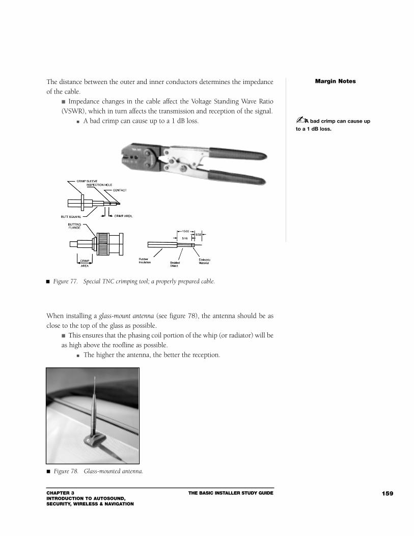
CHAPTER 3INTRODUCTION TO AUTOSOUND, SECURITY, WIRELESS & NAVIGATION
THE BASIC INSTALLER STUDY GUIDE 159
The distance between the outer and inner conductors determines the impedanceof the cable.
Impedance changes in the cable affect the Voltage Standing Wave Ratio(VSWR), which in turn affects the transmission and reception of the signal.
A bad crimp can cause up to a 1 dB loss.
When installing a glass-mount antenna (see figure 78), the antenna should be asclose to the top of the glass as possible.
This ensures that the phasing coil portion of the whip (or radiator) will beas high above the roofline as possible.
The higher the antenna, the better the reception.
Margin Notes
A bad crimp can cause up
to a 1 dB loss.
Figure 77. Special TNC crimping tool; a properly prepared cable.
Figure 78. Glass-mounted antenna.
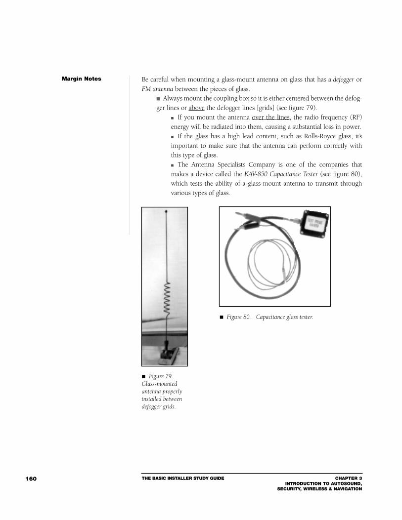
THE BASIC INSTALLER STUDY GUIDE CHAPTER 3INTRODUCTION TO AUTOSOUND,
SECURITY, WIRELESS & NAVIGATION
160
Be careful when mounting a glass-mount antenna on glass that has a defogger orFM antenna between the pieces of glass.
Always mount the coupling box so it is either centered between the defog-ger lines or above the defogger lines [grids] (see figure 79).
If you mount the antenna over the lines, the radio frequency (RF)energy will be radiated into them, causing a substantial loss in power. If the glass has a high lead content, such as Rolls-Royce glass, it’simportant to make sure that the antenna can perform correctly withthis type of glass. The Antenna Specialists Company is one of the companies thatmakes a device called the KAV-850 Capacitance Tester (see figure 80),which tests the ability of a glass-mount antenna to transmit throughvarious types of glass.
Margin Notes
Figure 79.Glass-mountedantenna properlyinstalled betweendefogger grids.
Figure 80. Capacitance glass tester.
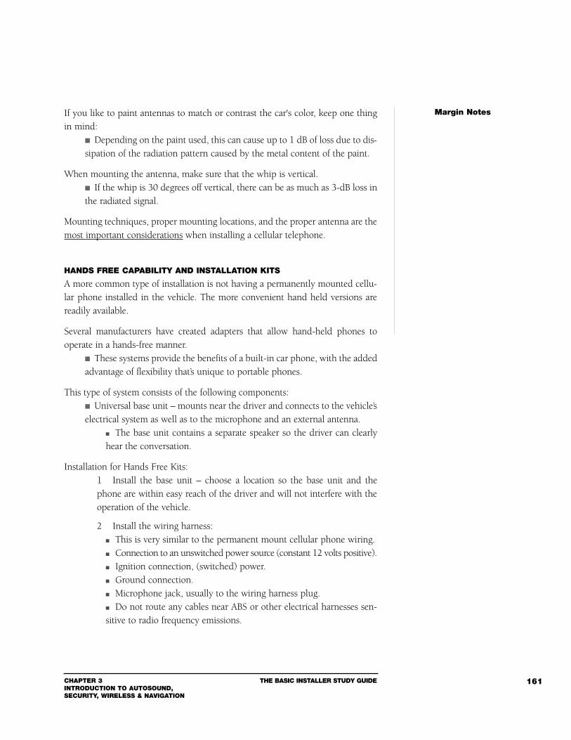
CHAPTER 3INTRODUCTION TO AUTOSOUND, SECURITY, WIRELESS & NAVIGATION
THE BASIC INSTALLER STUDY GUIDE 161
If you like to paint antennas to match or contrast the car's color, keep one thingin mind:
Depending on the paint used, this can cause up to 1 dB of loss due to dis-sipation of the radiation pattern caused by the metal content of the paint.
When mounting the antenna, make sure that the whip is vertical. If the whip is 30 degrees off vertical, there can be as much as 3-dB loss inthe radiated signal.
Mounting techniques, proper mounting locations, and the proper antenna are themost important considerations when installing a cellular telephone.
HANDS FREE CAPABILITY AND INSTALLATION KITS
A more common type of installation is not having a permanently mounted cellu-lar phone installed in the vehicle. The more convenient hand held versions arereadily available.
Several manufacturers have created adapters that allow hand-held phones tooperate in a hands-free manner.
These systems provide the benefits of a built-in car phone, with the addedadvantage of flexibility that’s unique to portable phones.
This type of system consists of the following components: Universal base unit – mounts near the driver and connects to the vehicle’selectrical system as well as to the microphone and an external antenna.
The base unit contains a separate speaker so the driver can clearlyhear the conversation.
Installation for Hands Free Kits:1 Install the base unit – choose a location so the base unit and thephone are within easy reach of the driver and will not interfere with theoperation of the vehicle.
2 Install the wiring harness: This is very similar to the permanent mount cellular phone wiring. Connection to an unswitched power source (constant 12 volts positive). Ignition connection, (switched) power. Ground connection. Microphone jack, usually to the wiring harness plug. Do not route any cables near ABS or other electrical harnesses sen-sitive to radio frequency emissions.
Margin Notes
THE BASIC INSTALLER STUDY GUIDE CHAPTER 3INTRODUCTION TO AUTOSOUND,
SECURITY, WIRELESS & NAVIGATION
162
3 Microphone installation is very similar to the installation of the handsfree microphone in the permanent mount cellular phone.
Position the microphone within 1 - 2 feet to the person speaking;route the microphone wire so it is out of the way for safe operation.
4 Connect the cable from the external antenna to the base unit.
PROGRAMMING
Programming the cellular phone is critical to its operation. Each cellular phonewill have its own unique programming sequence. Please refer to the individualmanufactures programming instruction for guidance with this area of installation.
Wireless Communications can be studied in greater depth in the MECP First Class
Study Guide.
Section 4Navigation Basics
Navigation systems are the latest frontier in the world of automotive electronics.These systems are, in essence, a sophisticated navigation computer that’s installedinto the vehicle. Then with the aid of the U.S. government’s Global PositioningSatellite (GPS) system, the driver is guided to his or her destination, or the vehi-cle can be tracked for the purpose of theft retrieval. This section will give theinstaller the basics of navigation type technologies and there installation.
These systems can take on different configurations: Stand-alone units.
Units that are integrated with the AM/FM/cassette/CD audio systems.
Units that have GPS/hybrid Wireless capabilities can provide two-waycommunication to a response center.
Units that only provide verbal navigation commands.
Units that provide verbal and visual navigation commands. Some can be accessed via a wireless remote control.
In essence, the goal of vehicle navigation systems is to do away with convention-al road maps by providing the driver with a system that plots the quickest routefrom Point A to Point B.
Margin Notes
CHAPTER 3INTRODUCTION TO AUTOSOUND, SECURITY, WIRELESS & NAVIGATION
THE BASIC INSTALLER STUDY GUIDE 163
TYPES OF NAVIGATION
Presently, there are four basic navigation systems in the marketplace:1 Voice activated.2 Telepath™.3 GPS locators.4 Advanced Route Guidance systems.
Voice ActivatedThe first voice activated navigation systems reached the market in early 1995.
A voice activated system operates via a specially designed CD or DVD thatcontains a database of roads, highways, landmarks and thousands of pointsof interest (POI).
Each street name, highway, city and POI has been recorded on the CD.
The CD or DVD is loaded into a specially designed changer or player.
The user can activate the system via microphone mounted in the car bysaying a specific word like, “Navigator.”
The voice activated system then asks a series of questions like: Where are you starting from? Where do you want to go? The system then gives you verbal commands, “Where to go next.”
Telepath™This system was developed by Delco Electronics (a division of General Motors).
Telepath uses the GPS signal to find its current location.
The user inputs their destination via a small LCD type display. Destinations can be entered via address, intersection, or landmark(such as “ATM” or “GAS”).
GPS LocatorsGPS Locator systems utilize a “moving map” on a video screen in the vehicle todirect the driver.
This system utilizes a digitized map of a specific area with “hidden” lon-gitude and latitude coordinates.
The system incorporates a GPS receiver. The GPS receiver must receive at least three GPS satellite signals todetermine the correct longitude and latitude coordinates.
The GPS information is then compared to the digitized map data. When the current location is found on the map, that image of themap is displayed on the screen.
Margin Notes
THE BASIC INSTALLER STUDY GUIDE CHAPTER 3INTRODUCTION TO AUTOSOUND,
SECURITY, WIRELESS & NAVIGATION
164
These systems rely only on the GPS signal to find the location of the vehicle. The U.S. government only guarantees GPS accuracy up to 300 feet, whichcan easily lead to errors on the map.
This system does not take into account vehicle speed or direction,therefore, turn-by-turn guidance is not completely accurate.
This system can show the driver their destination on the digitized map,but it’s up to the driver to figure out how to get from Point A to Point B.
Advanced Route Guidance SystemsThis type of system utilizes three different input sensors to determine the presentlocation and track the progress of the vehicle:
1 GPS antenna/receiver – uses GPS satellites to determine the currentposition of the vehicle.
2 Gyro sensor – determines the direction in which the vehicle turns.
3 Vehicle Speed Sensor (VSS) – determines how far and how fast thevehicle has traveled.
Thanks to the gyro sensor and speed sensor, these systems more accurately dis-play the vehicle’s position and track the vehicle’s progress – even when driving inareas where the GPS signal may be blocked
Here are the basic elements of an advanced route guidance navigation system:1 Main navigation ECU – the “brains” of the navigation system.Includes a built-in gyroscopic sensor, speed pulse sensor, GlobalPositioning Satellite receiver, and DVD or CD-ROM drive. It processes:
The incoming data from the vehicles speed sensor. The speed of the vehicle. The direction coming from the gyro sensor.
2 GPS antenna – receives incoming satellite signals. Antenna has a small footprint and some have a magnetic base. Designed to be mounted with inside applications as well as outsideof the vehicle. Antenna must have a clear view to the sky to receive satellite infor-mation. GPS reception can be slightly reduced when the antenna is mount-ed inside the vehicle.
Margin Notes
CHAPTER 3INTRODUCTION TO AUTOSOUND, SECURITY, WIRELESS & NAVIGATION
THE BASIC INSTALLER STUDY GUIDE 165
3 CD-ROM’s or DVD’s– contain the maps for each locale (which canbe updated periodically).
Some companies rely on universal mapping software. Other companies provide customized DVD or CD-ROM discs. DVD has the ability to store entire countries. On some systems, when you install the system, you have to install thecorrect CD for your geographic area – it’s not like changing music CDs. Other systems allow you to swap CDs when you change geographicareas. Use care when handling the DVD or CD-ROM. When the DVD or CD-ROM is removed from the ECU, place it inthe supplied jewel case. Do not expose to extreme heat.
4 Video monitors – displays directions. Some monitors include a built-in speaker. Has to be mounted within view of the driver. If customer is concerned about theft, some monitors are availablewith quick release brackets. Some monitors can be used to interface and control the audio system. Most monitors allow the driver to “zoom in” and “zoom out” to showmore or less detail on the map.
5 Remote control – many systems include a wireless remote control tohelp operate the navigation system.
Basics of InstallationThere are countless ways to install a navigation system. Accordingly, we do nothave the luxury of being able to cover each application. Therefore, we will coverthe basics.
As most of you already know (and as we discussed in Chapter 2), properly plan-
ning the installation will reduce the number of unprofitable service calls. Over 80% of all problems that occur with navigation systems can betraced back to installation problems.
Following are the basic guidelines you should follow when installing an AdvancedRoute Guidance Navigation System.
Margin Notes
THE BASIC INSTALLER STUDY GUIDE CHAPTER 3INTRODUCTION TO AUTOSOUND,
SECURITY, WIRELESS & NAVIGATION
166
Mounting the ECUOn some systems, the main navigation computer is designed to be mounted inthe trunk; on others, it can be mounted in the trunk or the glovebox (dependingon available space).
Find a suitable location for the ECU. Avoid any moving parts, places where moisture can arise, or loca-tions near extreme heat. Locations such as under the front seats, or hanging from the rearpackage tray work the best. The ECU must be mounted horizontal (less than 5°).
The gyro sensor mounted inside the ECU will not work properly when the unitis mounted on its side.
Mounting the AntennaThe GPS antenna needs to be mounted in a location that is the most “visible” tothe GPS satellites. Therefore, you need to carefully plan the location. When deter-mining the mounting location, follow these guidelines:
Do not mount under any metal surface. Some window tinting material has a high metal content (titanium),which can reduce the GPS antenna’s reception. Some newer vehicles – like the Oldsmobile Aurora – incorporatespecial heat resistant glass that will cause GPS reception problems. For those situations, it’s best to install the GPS antenna on the roofor the rear trunk lid. Mounting the antenna under dense plastics or cardboard may inhibitreception.
The GPS antenna can receive the needed signals when mounted inside thevehicle, but some precautions must be taken to ensure proper performance:
Mount the antenna in a location in the vehicle that allows the best“line-of-site” performance. Locations such as the rear package tray orfront dash work the best.
Secure the antenna with double sided tape or silicone. This helps prevent the magnetic base from moving and scratchingthe paint.
Carefully route the antenna cable and connect it to the ECU. The cable is matched to its length – do not shorten or extend. Avoid making sharp bends in the cable. Wind excess cable into large loops.
Margin Notes
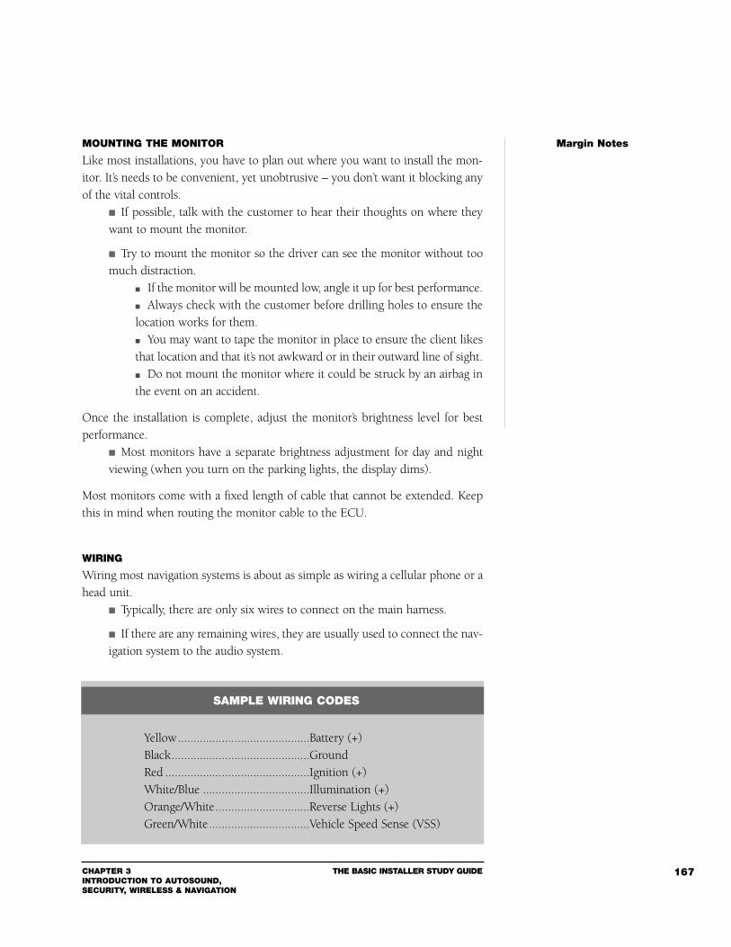
CHAPTER 3INTRODUCTION TO AUTOSOUND, SECURITY, WIRELESS & NAVIGATION
THE BASIC INSTALLER STUDY GUIDE 167
MOUNTING THE MONITOR
Like most installations, you have to plan out where you want to install the mon-itor. It’s needs to be convenient, yet unobtrusive – you don’t want it blocking anyof the vital controls.
If possible, talk with the customer to hear their thoughts on where theywant to mount the monitor.
Try to mount the monitor so the driver can see the monitor without toomuch distraction.
If the monitor will be mounted low, angle it up for best performance. Always check with the customer before drilling holes to ensure thelocation works for them. You may want to tape the monitor in place to ensure the client likesthat location and that it’s not awkward or in their outward line of sight. Do not mount the monitor where it could be struck by an airbag inthe event on an accident.
Once the installation is complete, adjust the monitor’s brightness level for bestperformance.
Most monitors have a separate brightness adjustment for day and nightviewing (when you turn on the parking lights, the display dims).
Most monitors come with a fixed length of cable that cannot be extended. Keepthis in mind when routing the monitor cable to the ECU.
WIRING
Wiring most navigation systems is about as simple as wiring a cellular phone or ahead unit.
Typically, there are only six wires to connect on the main harness.
If there are any remaining wires, they are usually used to connect the nav-igation system to the audio system.
Margin Notes
SAMPLE WIRING CODES
Yellow..........................................Battery (+)Black............................................GroundRed ..............................................Ignition (+)White/Blue ..................................Illumination (+)Orange/White..............................Reverse Lights (+)Green/White................................Vehicle Speed Sense (VSS)
THE BASIC INSTALLER STUDY GUIDE CHAPTER 3INTRODUCTION TO AUTOSOUND,
SECURITY, WIRELESS & NAVIGATION
168
In general, the basic connections for power, ground, ignition and illuminationshould be very straightforward.
The reverse light input is a necessary connection. The navigation unitmust know when the vehicle is driving in reverse, so it can compensatewhen determining the precise location of the vehicle.
It can typically be found at the transmission switch, the main wireharness that runs to the tail lights or at the reverse light itself.
The most difficult wire to find will be the VSS wire. Some manufacturers, have a special Application Support team that helpsinstallers locate the VSS wire.
Caution: Some older vehicles may not have VSS wires. Under those circum-stances, you must install a speed pulse generator onto the speedometer cable.
VEHICLE SPEED SENSOR TESTING AND VERIFICATION
Once the Vehicle Speed Sensor (VSS) has been installed, you have to test to makesure it is functioning, and then verify its accuracy. There are two types of VehicleSpeed Sensors:
1 Analog2 Digital
Analog VSSNOTE: If you’re working with an analog VSS, DO NOT hook up the analog speedpulse wire to the navigation system before undergoing the initialization process.
Analog speed pulse is measured as AC voltage with reference to chassis ground. Due to varying AC voltages and frequencies, the only accurate way to ver-ify an analog speed pulse is to use an oscilloscope.
If you do not have access to an oscilloscope, verify that the wire doesnot have a positive DC voltage by using your digital multimeter. Next, set your digital multimeter to AC voltage at the 30-volt rangeor on auto-range. Connect the black lead of the multimeter to chassis ground. Probe the speed pulse wire with the red lead. The meter should read zero volts. Start the car and drive slowly (you should have someone riding withyou to read the multimeter while you drive).
Margin Notes
CHAPTER 3INTRODUCTION TO AUTOSOUND, SECURITY, WIRELESS & NAVIGATION
THE BASIC INSTALLER STUDY GUIDE 169
The meter should slowly begin to show an increase in voltage. At slower speeds, the voltage should be approximately 2 - 5 volts AC. As vehicle speed increases, AC voltage will increase. Maximum AC voltage should be somewhere around 5 - 8 volts at 60 mph.
Do not confuse this process with checking the tachometer wire. The tachometerwire increases voltage with the engine’s RPM. The speed pulse wire increases volt-age with the vehicle's actual speed.
After verifying the analog speed pulse wire, you must follow certain procedures toinitialize the navigation system to accept an analog speed pulse prior to attachingthe wire to the system.
Check the manufacturer’s installation instructions for the proper procedures.
Digital VSSTo test and verify a digital VSS, you will need a digital multimeter set to DC Voltsat the 30-volt range or on auto-range.
Be sure to question the customer so you understand the powertrain lay-out of the vehicle.
For front-wheel drive, jack up only one of the front two wheels. For rear-wheel drive, jack up only one of the rear wheels. For all-wheel drive vehicles, you will need to jack up all of the drivewheels (if you cannot switch to 100% rear-wheel drive or 100% front-wheel drive). For 4-wheel drive vehicles that drive only the rear wheels when in2-wheel drive mode, jack up only one of the rear wheels. For vehicles with a locking differential, you will need to jack up both(or all) of the drive wheels. Be sure to block the remaining wheels to prevent the vehicle fromrolling.
Connect the Black lead of the multimeter to chassis ground.
Probe the speed pulse wire with the Red lead.
Turn the ignition key to the “ON” position, but do not start the vehicle.
Read the multimeter.
It should show zero volts (off) or a voltage ranging from 5 - 12 volts (on). The voltage range will differ depending upon the vehicle, however it willnot fluctuate.
Margin Notes
THE BASIC INSTALLER STUDY GUIDE CHAPTER 3INTRODUCTION TO AUTOSOUND,
SECURITY, WIRELESS & NAVIGATION
170
Rotate the tire slowly.
The voltmeter should change state between zero volts (off) and 5 - 12volts (on) or vice-versa within 2-3 rotations of the tire.
That is all you have to do to verify the digital speed pulse.
TESTING THE SYSTEM
Unlike your typical installation, a navigation system is not fully functional the firsttime you switch it on. For example, you have to allow the ECU time to get “insync” with the GPS satellites.
Follow these guidelines: Park the vehicle in an area outside where the GPS antenna has goodreception.
Make sure the vehicle is away from tall buildings or trees.
Turn on the unit. This process takes between 10 and 30 minutes while the systemreceives the GPS data and finds the approximate vehicle location.
Once the unit “wakes up,” typically a disclaimer screen will appear.
Press the “ENTER” button.
The map screen should appear. In some instances, the vehicle icon may appear on a blank mapscreen (no roads are illustrated) – this condition is normal.
Somewhere on the screen will be a GPS signal icon (it should be in theshape of a satellite).
Once the unit receives the GPS data, the GPS icon will change (insome instances, it will change color – from dark gray [no reception], tolight blue [minimum reception], to yellow [maximum reception]).
The vehicle icon should now be visible on the map, and the monitor should showthe approximate vehicle location.
Don’t worry if the map position is a block or so away from your actual position –the system will correct itself as you drive.
These are only basic guideline for installation. For further guidelines consult theindividual GPS manufacturer.
Navigation Systems can be studied in greater depth in the MECP First Class Study Guide.
Margin Notes
CHAPTER 3INTRODUCTION TO AUTOSOUND, SECURITY, WIRELESS & NAVIGATION
THE BASIC INSTALLER STUDY GUIDE 171
SAMPLE TEST QUESTIONS
1 At what frequency is the human ear most sensitive?A 25 Hz to 35 Hz.B 100 Hz to 250 Hz.C 1000 Hz to 2000 Hz.D 15000 Hz to 20000 Hz.
2 What is sympathetic vibration?A Noises made by processors.B The natural resonance of an object.C Distortion.D Ignition noise.
3 An audio signal is an electrical representation of what?A Sound Wave.B Octave.C Potentiometer.D Inductance.
4 Destructive interference refers to two speakers whose sound waves are work-ing against each other and our out of phase by:
A 45º degrees.B 90º degrees.C 180º degrees.D 270º degrees.E 360º degrees.
5 A Magnetic Reed Switch, also called a magnetic proximity switch: A Uses magnetic force to cause a set of contacts to connect.B Uses kinetic energy to open and close a set of contacts.C Has input for multiple switch triggers.D Can replace the use of a relay.
6 The most common used device to interrupt a vehicle’s starter is a:A Electronic switching capacitor.B Heavy duty diode.C Electromagnetic switch.D Pulse timer.
Margin Notes
THE BASIC INSTALLER STUDY GUIDE CHAPTER 3INTRODUCTION TO AUTOSOUND,
SECURITY, WIRELESS & NAVIGATION
172
7 Is an impact sensor the best device to detect breaking glass during a break inattempt?
A TrueB False
8 A “pulse” or universal timer can be used to: A Remove unwanted EMI from you security system.B Add a pulsed output for alternating flashing parking lights.C Convert a momentary duration pulse into a longer or shorter duration
signal.D Reverse the pulse from negative to positive for door triggers.
9 A glass mount antenna will transmit and receive best:A When mounted over two defogger grids.B When it is mounted over an FM antenna grid.C When mounted between or above the defogger grids.D When place at a 45º degree angle to the ground plane.
10 Extending the length of the RG 58 coax cable supplied by the manufacture(normally 12-15 feet) can result in as much as 3 dB of signal loss.
A TrueB False
11 The small holes on the side of the hands free microphone are commonlyused for:
A Decoration.B Noise canceling.C The mounting clip.D Have no specific purpose.
12 Painting cellular antenna mast with car paint can typically cause up to 1 dBof loss.
A TrueB False
Margin Notes

CHAPTER 3INTRODUCTION TO AUTOSOUND, SECURITY, WIRELESS & NAVIGATION
THE BASIC INSTALLER STUDY GUIDE 173
13 Which of the following materials will not attenuate the signal from a GPSantenna:
A Metallic window tint.B Line defrosters.C Electrically heated windshields.D Factory pigment tinted glass.
14 The best choice of mounting position for the GPS antenna is:A Under the trunk lid.B Under the hood.C Under the headliner.D On the rear deck or dash.E On the center console.
15 The length of antenna cable on a GPS receiver is;A Unmatched.B Preset.C Random.D Uncorrelated.
16 A true VSS signal will vary in proportion with;A Engine temperature.B Engine RPM.C Ignition voltage.D Battery voltage.E Vehicle speed.
Answers1 C, 2 B, 3 A, 4 C, 5 A, 6 C, 7 B, 8 C, 9 C, 10 A 11 B 12 A 13 D 14 D 15 B 16 F
Margin Notes


GLOSSARY OF TERMS
Glossa
ry of Te
rms
THE BASIC INSTALLER STUDY GUIDE GLOSSARY OF TERMS176
AC (Alternating Current) – Energy that alternates back and forth at a certain fre-quency. The frequency is measured in hertz. In automobiles, AC is produced bythe alternator and then rectified to DC.
Acoustical Energy – Energy consisting of fluctuating waves of pressure calledsound waves.
Acoustics – A science dealing with the production, effects, and transmission ofsound waves through various mediums.
Active Arming – A method for arming a security system that requires some actionby the driver/operator. This action could include pressing a button on a remotetransmitter or entering a code on a keypad.
Air Horns – A type of horn that uses compressed air instead of an electricdiaphragm or voice coil to produce sound. These horns are usually driven by anelectric air pump that receives its trigger from a host security system.
Alarm Reset – The property of an alarm system that resets the alarm to analarmed state after a pre-determined period of time.
Alarm Re-triggering – A condition that occurs in a security system that has beentriggered. Instead of sounding the siren for its designated time interval, it is re-triggered and made to sound again.
Alternator – A mechanically driven automotive device that generates DC power;it is the primary source of vehicle power.
Alternator Whine – A siren-like whining that occurs when an engine’s RPMsincrease. The noise is usually the result of a voltage differential created by morethan one ground path or a poor ground path.
Ambience Synthesizer – A unit that produces an artificial ambience pattern; onethat is used to create the impression of the listener and/or performer being in aparticular performance space.
Ammeter – An instrument used for measuring the amount of current flowing ina circuit.
Amperage – A unit of electrical current; the force through which the energy ispushed through a conductor. Measured in amps; Ohm’s Law symbol is I.
Margin Notes
GLOSSARY OF TERMS
A B C
GLOSSARY OF TERMS THE BASIC INSTALLER STUDY GUIDE 177
Ampere – The unit of measurement used to determine the quantity of electricityflowing through a circuit. One ampere flows through a 1 Ohm resistance when apotential 1 Volt is applied.
Amplification – An increase in signal level, amplitude, or magnitude.
Amplitude – The measure of how powerful sound waves are in terms of pressure.
Amplitude Modulation (AM) – A method of modulation in which the amplitudeof the carrier voltage is varied in proportion to the changing frequency value of anapplied (audio) voltage. (See also Frequency Modulation)
Analog – An electrical signal in which the frequency and level vary continuouslyin direct relationship to the original acoustical sound waves. Analog may also referto a control or circuit which continuously changes the level of a signal in a directrelationship to the control setting.
Analog Switch – A hardware-oriented switch that only passes signals that arefaithful analogs of transducer parameters.
Anode – The electrically positive pole of an electronic device such as a semicon-ductor. A diode, for instance, has a positive and a negative pole; these are knownas the anode and the cathode.
Antenna – A mechanical device, such as a rod or wire, that picks up a receivedsignal or radiates a transmitted signal.
Arm – The term used to describe the act of causing a security system to reach astate in which it will protect the vehicle.
Arming Delay – A term used to describe the elapsed time between the momenta security system is first told to arm and the moment it is actually armed. Thisnormally applies only to systems that are passively armed, but it can apply toactively armed systems, as well.
Attenuate – To lessen the amount of force, magnitude, or value of something.
Audio Frequency Spectrum – The band of frequencies extending roughly from20 Hz to 20 kHz.Audio Oscillator – A device that produces tones at specific frequencies for test-ing either equipment or entire systems.
Audio Signal – An electrical representation of a sound wave in the form of alter-nating current (AC) or voltage.
Margin Notes
THE BASIC INSTALLER STUDY GUIDE GLOSSARY OF TERMS178
Auto Reset – The ability of a security system to automatically reset itself afterbeing triggered.
Back-up Battery – A separate battery added to the security system as an alternatepower supply to serve as a backup in case the vehicle’s main battery is disabled bya thief. Back-up batteries are typically the lead-acid gel cell type and are mosteffective when hidden from detection.
Ballast Wire – The name given to a special resistance wire used between the igni-tion switch and the engine’s high voltage coil.This wire is typically composed of acarbon compound instead of normal copper.
Bandpass Filter – In mobile electronics, a device which incorporates both high-pass and low-pass filters in order to limit and attenuate both ends of the frequen-cy range.
Bandwidth – Refers to the “space” in the frequency response of a device throughwhich audio signals can pass (between lower and upper frequency limits, thosepoints where the signal level has rolled off 3 dB).
Bass – The low audio frequency range, normally considered to be below 500 Hz.
Bass Reflex – a vented enclosure that allows control of rear radiated sound waves.
Battery – A device that stores electrical energy. A battery makes direct currentthrough a collection of cells.
Bias – An unbalanced sound level.
Boomy – Usually refers to excessive bass response, or a peak in the bass responseof a recording, playback, or sound reinforcement system.
Bridging – Bridging combines two channels of an amplifier to turn it into a onechannel amplifier.
Brain – The common term used to refer to the main control unit of a security sys-tem. (See also Control Unit)
Butterworth Filter – A filter with a pass-band with no ripple but usually sacri-fices some steepness in attenuation.
Margin Notes
GLOSSARY OF TERMS THE BASIC INSTALLER STUDY GUIDE 179
Capacitance – The property exhibited by two conductors separated by a dielec-tric, where an electric charge becomes stored between the conductors. (Also seeFarad.)
Capacitor – An electronic device that stores energy and releases it when needed.Also used to direct high-frequency energy to tweeters. Rated in Farads.
Cathode – The electrically negative pole of an electronic device such as a semi-conductor.
CDPD (Cellular) – Cellular digital packet data. Digital data non-voice two-waycommunications transmitted in the cellular band.
Cell – A single unit for producing DC electricity by electrochemical or biochem-ical action. A common vehicle battery is composed of a number of individual cellsconnected together. Each cell is typically rated at 2.11 volts; a common 12VDCautomotive battery is composed of six separate two-volt cells.
Cellular Telephone – A device consisting of a control unit, a transceiver, and anantenna that processes calls to be sent to or received from the cellular system.
Channel (Cellular) – A frequency or band of frequencies assigned to a station orcommunications system. Also, a sub-circuit of a larger system (e.g., voice chan-nel, control channel, paging channel).
Channel (security) – The term used to describe the number of different func-tions possible for manipulating the buttons on a remote control transmitter.
Chassis – The metal frame of the vehicle.
Chebyshev Filter – A filter that has some ripple in the pass-band but has an ini-tial attenuation slope which is steeper than a Butterworth filter.
Chirp – The term used to describe the brief sounding of a security system’s sirendesigned to indicate the state of arm of the system.
Circuit – A closed path through which current flows from a power source,through various components, and back to the power source.
Circuit Breaker – An electromechanical device designed to quickly break theelectrical connection should a short circuit or overload occur. A circuit breaker issimilar to a fuse, except it will reset itself or can be manually reset, and will againconduct electricity.
Margin Notes
THE BASIC INSTALLER STUDY GUIDE GLOSSARY OF TERMS180
Clipping – Distortion that occurs when a power amplifier is overdriven. This canbe seen visually on an oscilloscope, when the peaks of a waveform are flattened,or “clipped off,” at the signal’s ceiling.
Closed Circuit – A continuous unbroken circuit in which current can flow with-out interruption. Also known as a closed loop.
Closed Loop – A feedback path in a self-regulating control system. Unlike a stan-dard open state trigger that needs to have a connection established to serve as atrigger, a closed loop trigger will act to trigger a security system when its loop(connection) is broken.
Closure Wire – The name given to describe a wire found on some vehicles that,when given a certain duration input, will cause the doors to lock and the win-dows/sunroof to close.
Code – The aspect of a security system that can be tailored by the manufactureror the installer to personalize the particular system for a user or group of users. Aremote security system that is coded will operate only with those transmitters thatare coded to the same code.
Coaxial Speaker – A coaxial speaker has a large cone for the low range and a small-er tweeter for the high spectrum. There is a crossover network that divides androutes the signal to the correct driver. Named for two speakers sharing a single axis.
Co-Linear Antenna – An antenna that uses a phasing coil to electrically connectstacked elements in the proper phase relationship.
Compliance – The measurement in liters or cubic feet of the volume of air that isequal to the compliance of a speaker’s total suspension.
Cone – The most common shape for the radiating surface of a loudspeaker. Oftenused to refer to the part of the speaker that actually moves the air.
Control Unit – The central processor for a security system.
Constant Output – An output of a security system that provides a constant orcontinuous output to drive a device. Often used for sirens and engine interrupts.
Control Unit – The central processor for a security system. (Also see Brain.)
Coulomb – An amount of electrical charge which contains 6.24 x 10¹⁸ of electrons.
Crossover – A device that separates the different frequency bands and redirectsthem to different components.
Margin Notes
GLOSSARY OF TERMS THE BASIC INSTALLER STUDY GUIDE 181
Crossover Frequencies – The frequencies at which a passive or electroniccrossover network divides the audio signals, which are then routed to the appro-priate speakers.
Crossover Network – A unit that divides the audio spectrum into two or morefrequency bands.
Current – The rate of electrical or electron flow through a conductor betweenobjects of opposite charge. Symbol I, measured in amperes or amps.
Current-fed Antenna – An antenna in which the feeder or transmission line isattached to the radiator at a current loop. This type of antenna requires a groundplane.
Current Sensing – A name given to a form of alarm system trigger that relies onsensing a change in the power supply of the vehicle. More accurately called volt-age sensing, this feature is found on many inexpensive alarms.
Damping – The reduction of the magnitude of resonance by the use of some typeof material. The damping material converts sound to energy, then disperses theenergy by converting it to heat.
DAT – Digital Audio Tape.
DC – Direct Current. A flow of electrons that travels only in one direction.
Decibel (dB) – The standard unit of measurement used to indicate the relativeintensity of sound.Dedicated Fuse – A fuse designated to supply power and protection for one par-ticular circuit only.
Destructive Interference – A phenomenon that occurs when speakers are 180degrees out of phase. For example, what one speaker is trying to produce, the otherspeaker is fighting to cancel. One speaker’s wave is in the positive phase (com-pression), while the other speaker’s wave is in the negative phase (rarefaction).
Diaphragm – A thin metal or dielectric disk used as the vibrating member inloudspeakers. Also known as a cone.
Margin Notes
D E F
THE BASIC INSTALLER STUDY GUIDE GLOSSARY OF TERMS182
Difference of Potential – The algebraic sum of voltages at two points of differentelectrical potential.
Diode – A two-electrode (two-terminal) device that allows a voltage/signal to passthrough it in one direction only.
DIN – Deutscher Industrie Normen. German industrial standards that are used inmany European countries. DIN size refers to the stereo size that fits mostEuropean cars.
Disarm – The opposite of arm, or the term used to describe the action of placinga security system in an inactive or standby mode.
Distortion – Sound that is modified or changed in some way. In a speaker, dis-tortion is produced by several factors, many of which are related to poor con-struction. Voice coil rubbing (caused by being overdriven) is the most commoncause of distortion.
DMM – Digital Multimeter. A digital meter that gives a precise reading of voltage,current, or ohms. This type of meter “samples” the input and feeds it to a digitalreadout.
Dolby System – A unique patented noise reduction system that electronicallyeliminates the irritating noise (tape hiss, circuit noise, etc.) without sacrificing theoriginal tonal quality.
Dome Light – The common term used to describe the overhead (or headliner)mounted interior courtesy light.
Door Lock Solenoid – The proper name for the electric bi-directional actuatorused to provide powered control of vehicle door locks. Also called a Door LockActuator.
Doppler Sensor – Another name for a spatial type sensor, also commonly calleda radar sensor.
DPDT – Double Pole Double Throw. A term used to describe a relay that has twoseparate poles or contacts and can throw or make electrical contact with two sep-arate stationary contacts.
Dress – The arrangement of signal leads and wiring for optimum circuit opera-tion, cosmetic appeal, and protective routing.
Driver – Another term for a loudspeaker. Often used when the loudspeaker iscoupled with a horn for acoustic coupling and controlled dispersion of sound.
Margin Notes
GLOSSARY OF TERMS THE BASIC INSTALLER STUDY GUIDE 183
DSP – Digital Signal Processing (or Processor). A type of processing accomplishedby a micro-computer chip specifically designed for signal manipulation, or a com-ponent using such processing. The term is often misused as a synonym for ambi-ence synthesizer; however, DSP can do much more than sound field creation.
Duty Cycle – An engineering term used to describe the actual time (or frequency)that a circuit or device operates. A pulsing alarm output that is on for seven-tenthsof a second and off for three-tenths of a second would have a 70% duty cycle.
Dynamic Range – The range difference between the quietest and the loudest pas-sages of the musical selection or program signal being played.
Efficiency – The measurement of a loudspeaker’s ability to convert power towork. Formula: Efficiency = (power out/power in) x 100. Efficiency is alwaysexpressed as a percentage.
Electrolyte – The name for the mixture of diluted sulfuric acid found in standardlead-acid vehicle storage batteries.
Electrolytic Capacitor – A capacitor with a negative and a positive terminal thatpasses only alternating current. Electrolytics are available in polarized and non-polarized configurations. Non-polarized (NP) capacitors are useful as inexpensivecrossovers, blocking low frequencies from passing through to mid- or high-fre-quency speakers. Polarized capacitors have specific positive and negative poles.This type of capacitor is useful for storing and releasing energy.
Emergency Override – A button or switch, possibly separate or hidden from thecommonly used controls of a security system, that is used specifically to overrideor disarm a security system in the event that the primary means is unavailable ordisabled.
EMR Detector – A tool used to find the source of low-frequency tape head inter-ference (electromagnetic radiation, or EMR).
Engine Disable – A means, either electrical or mechanical, of preventing the vehi-cle’s engine from either starting or running. The most common variety of enginedisable uses a simple automotive relay to inhibit either the starter or the ignition.
Entry Delay – The time interval a security system waits before sounding thealarm after a vehicle’s door has been opened.
ESN – A phone’s electronic serial number.
Margin Notes
THE BASIC INSTALLER STUDY GUIDE GLOSSARY OF TERMS184
Exit Delay – The name given to the amount of time a security system waits onceit’s given a command to arm. Exit delays are usually found on non-remote secu-rity systems that rely on keypads or the ignition switch to arm. This delay givesthe operator time to exit the vehicle before the system arms.
Farad (F) – The basic unit of capacitance. A capacitor has a capacitance of 1Fwhen a charge of 1 volt across the capacitor produces a current of 1 amperethrough it. Named after Michael Faraday.
FCC – Federal Communications Commission. The U.S. government agency thatoversees and regulates electronic communications.
Fidelity – A term used to describe the accuracy of recording, reproduction, orgeneral quality of audio processing.
Flashing Lights – A term used to describe the interfacing of the vehicle’s parkinglights, dome light, emergency lights, etc., with a security system so that the lightsflash by the system.
Flat Response – An output signal in which fundamental frequencies and har-monics are in the same proportion as those of the input signal being amplified. Aflat frequency response would exhibit relatively equal response to all fixed-pointfrequencies within a given spectrum.
Fletcher-Munson Curves – A set of curves that depict the uneven frequencyresponse of human hearing.
FM – See Frequency Modulation.
Free Air Resonance – The frequency at which a speaker will naturally resonate.
Frequency – The term in physics that refers to a number of vibrations or cyclesthat occur within a given time.
Frequency Counter – A device that assists in speaker parameter testing, as wellas identifying the frequency of specific tones.
Frequency Modulation (FM) – A method of modulation in which the frequen-cy of the carrier voltage is varied with frequency of the modulating voltage (Seealso Amplitude Modulation)
Margin Notes
GLOSSARY OF TERMS THE BASIC INSTALLER STUDY GUIDE 185
Frequency Response – A term that describes the relationship between a device’sinput and output with regard to signal frequency and amplitude.
Fundamental Frequency – The lowest frequency component of a harmonic series.
Fuse – A device designed to provide protection for a given circuit or device by phys-ically opening the circuit. Fuses are rated by their amperage and are designed toblow or open when the current being drawn through it exceeds its design rating.
Fusible Link – Designed to perform the same task as a fuse, but resembles a wire.Fusible links are commonly used in ignition switches and other high-current circuits.
Gain – Refers to the degree of signal amplification.
Generator – A rotating machine that produces DC electricity. Also an electronicdevice used for converting DC voltage into AC of a given frequency and wave shape.
Glass Sensor – A device designed to detect the sound of breaking glass or metal-to-glass contact, thus triggering a security system. Also called sound sensors,glass-breaking sensors, or sound discriminators.
Ground – The term given to anything that has an electrical potential of zero. Mostmodern vehicles are designed around a negative ground system, with the metalframe being the vehicle’s ground.
Ground Loop – The term given to the condition that occurs when a voltagepotential exists between two separate ground points.
Harmonic – The overtones and undertones that define the acoustic differencebetween two sounds with the same fundamental frequency.
Harness – The universal name for a bundle or loom of wires that compose thewiring for a system.
Headroom – The difference between the highest level present in an audio signaland the maximum level an audio device can handle without noticeable distortion.
Hertz (Hz) – The unit of frequency within a specific period, such as alternatingor pulsating current; 1 Hz = 1 cycle per second.
Margin Notes
G H I
THE BASIC INSTALLER STUDY GUIDE GLOSSARY OF TERMS186
High Frequency – Refers to radio frequencies in the 3-30 MHz band. In audio itusually refers to frequencies in the 5-10 kHz band.
High Pass Filter – A network of components which attenuate all frequenciesbelow a predetermined frequency selected by the designer. Frequencies abovecut-off are passed without any effect.
Horn (Audio) – Refers to a loading device when part of a bass enclosure, or adirectional device when used with a high-frequency driver or compression driver.
Horn (Security) – Refers to the built-in factory horn in the vehicle. Factory hornscan be of the diaphragm type, voice coil type, or air-pump driven type (air horn).All types of horns can be interfaced to a security system.
Ignition Kill – A device designed to prevent the vehicle’s ignition circuit fromoperating. An ignition kill device can work by either interrupting one or both ofthe primary wires leading to the ignition coil or by shorting out (grounding) theignition coil’s positive primary wire. Also called Ignition Disable.
Ignition Power – Refers to a source of power in the vehicle, controlled by theignition switch, that has +12VDC on it when the ignition key is not in the run andstart positions.
Imaging – The width and definition of a sound stage. Instruments should appearto be coming from their correct positions, relative to recording.
Impact Sensor – A sensor designated to detect various degrees of impact or vibra-tion applied to the vehicle and then produce an output to trigger a security system.
Impedance (Audio) – A measurement of the resistance to the audio current bythe voice coil of the speaker. (See also Nominal Impedance)
Impedance (Electrical) – The total opposition offered by a device or circuit tothe flow of alternating current (AC).
Inductive Coupling – Radiated noise that is transmitted through a magnetic fieldto surrounding lines.
Inductor – An electrical component in which impedance increases as the fre-quency of the AC decreases. Also known as coils that are used in passivecrossovers. Inductors are rated in Henries.
Margin Notes
GLOSSARY OF TERMS THE BASIC INSTALLER STUDY GUIDE 187
Infinite Baffle – A loudspeaker baffle of infinite space that has no openings forthe passage of sound from the front to the back of the speaker. Also, a sealedenclosure where the internal volume is greater than the Vas of the driver.
Infrared Sensor – A type of spatial sensor that uses infrared energy to detect anobject (a hand, arm, or body) entering a protected area. (See also Spatial Sensors)
Input (Audio) – The high-level (speaker) or line level (RCA) signal connectionsthat run into one component from another system component.
Input (Security) – Any wire on a security system designed to accept a signal fromsome outside source such as the vehicle’s wiring. Door trigger, hood trigger, trunktrigger, and sensor trigger wires are all inputs.
Instant Trigger – The term used to describe any trigger input on a security sys-tem that is designated to cause the system to respond instantly when triggered.
Integrity – The expected durability of a component or connection.
Joule – A unit of energy equal to one watt per second.
Jump – To provide a temporary circuit around a component or other circuit.
Keypad – A panel usually made of metal or plastic with numbered push-buttons(like a touch-tone telephone) designed to provide access to certain types of secu-rity or cellular systems.
Kirchoff’s Current Law (KCL) – A law stating that the total current entering apoint or junction in a circuit must equal the sum of the current leaving that pointor junction.
Kirchoff’s Voltage Law (KVL) – A law stating that the voltage supplied to a DCcircuit must equal the sum of the voltage drops within the circuit.
kHz – Abbreviation for kilohertz, or 1000 cycles per second.
Margin Notes
J K L
THE BASIC INSTALLER STUDY GUIDE GLOSSARY OF TERMS188
Last Door Arming – A feature found on some security systems that enables thesystem to suspend itself from arming until the last door of the vehicle has beensecured.
LCD – Liquid Crystal Display.
LEDs – Light Emitting Diodes. A form of diode that sheds light. Used in may sys-tems for indicator purposes.
Loudspeaker – An electro-acoustic transducer that converts electrical audio sig-nals at its input to audible sound waves at its output.
Low Frequency – Refers to radio frequencies within the 30 -300 kHz band. Inaudio it usually refers to frequencies in the 40-160 Hz band.
Low Pass Filter – A network of components which attenuate all frequenciesabove a predetermined frequency selected by the designer. Frequencies belowcut-off are passed without any effect.
Magnet – A device that can attract or repel pieces of iron or other magnetic mate-rial. Speaker magnets provide a stationary magnetic field so that when the coil pro-duces magnetic energy, it is either repelled or attracted by the stationary magnet.
Memory – The word most commonly used to refer to a system’s ability to retainspecific information.
Microprocessor – A semiconductor that can be programmed to perform a vari-ety of tasks in many different systems.
Midrange Driver – A loudspeaker specifically designed to reproduce the fre-quency in the middle of the audible bandwidth. Most musical energy lies in themidband.
Milliamps – A unit of measurement of electrical current equal to 1/1000th of anampere. The milliampere is the most common unit used when measuring quies-cent (minor) current drain.
Module – A term commonly used to describe a self-contained part or device thatcan perform a specific function.
Margin Notes
M N O
GLOSSARY OF TERMS THE BASIC INSTALLER STUDY GUIDE 189
Motion Sensors – A sensor specifically designed to detect a gentle or sharp up-and-down or side-to-side motion of the vehicle.
Multimeter – A common term used to describe a Volt-Ohm-Meter, or VOM. Amultimeter usually can measure volts, ohms, and amperes or milliamperes.
Negative Door Switches – A common type of switch found on most modernvehicles which provides the trigger for the factory interior lights, key buzzer, fac-tory alarm, etc.
Negative Lead – The lead or line connected to the negative terminal of a current,voltage, or power source.
Noise Floor – The noise power generated by an audio device in the absence ofany input signal. It is generally measure in decibels.
Nominal Impedance – The minimum impedance a loudspeaker presents to anamplifier, directly related to the power the speaker can extract from the amplifier.
Normally Closed – Refers to the electrical state in which a switch may rest. Itscontacts are held together or closed so that current is allowed to flow through itscontacts.
Normally Open – Refers to the electrical state in which a switch may rest. Its con-tacts are held apart or open so that no current flows through its contacts.
Octave – A musical interval between two tones formed when the ratio betweenthe frequencies of the tone is 2:1.
Ohm – The unit of measurement for electrical resistance.
Ohm’s Law – The statement of the relationship between current, voltage, and resis-tance. Where I = Current, E = Voltage, and R = Resistance, I=E/R, E=IR, and R=E/I.
Open Circuit – A circuit containing a switch, filament, voice coil, etc., which isnot intact and current cannot flow through.
Oscillator – A device that produces an alternating current or pulsating current orvoltage electronically.
OSHA – Occupational Safety and Health Administration. The U.S. governmentagency that regulates workplace safety and health.
Margin Notes
THE BASIC INSTALLER STUDY GUIDE GLOSSARY OF TERMS190
Output (Audio) – The high-level (speaker) or line-level (RCA) signals sent fromone system component to another, or the high-level signal from an amplifier tothe system speakers.
Output (Security) – Any wire on a security system designed to produce a signalintended to be wired to some outside circuit or device. Siren wires, flashing lightwires, and door locks are all outputs.
Override Switch – A switch that provides a secondary means to disarm or over-ride a security system in the event the primary means is unavailable. (See alsoEmergency Override)
Pager – A device designed to transmit a signal to the owner of a vehicle in orderto alert him or her that the alarm has been triggered.
Pain Generator(s) – A name given to a type of siren that is specifically designedto produce a sound of the proper volume and pitch so as to cause physical painto a thief’s ears.
Panic – The name given to the feature of a security system that provides the abil-ity to the operator to cause the system’s siren to sound at will. The panic featureis typically initiated either by pressing a button or buttons on the remote controltransmitter by keypad command, by push button, or by toggle switch.
Parallel Wiring – A circuit in which two or more devices are connected to thesame source of voltage, sharing a common positive and negative point, so thateach device receives the full applied voltage.
Passive Arming – The ability of some security systems to arm without requiringany direct action from the operator of the vehicle. Passive arming is usuallyaccomplished when the operator exits the vehicle in the normal fashion. (See alsoLast Door Arming)
Passive Crossover – An electrical circuit consisting of capacitors, inductors, andresistors designed to separate an audio signal into specific speaker groups.
Passive Repeater Antenna – A non-permanently installed, glass-mount antennathat is without physical connection to the cellular telephone.
Margin Notes
P Q R
GLOSSARY OF TERMS THE BASIC INSTALLER STUDY GUIDE 191
PCS (Cellular) – Personal communications system. Hand-held telephones thatoperate in bands of 1900 megahertz and above.
Peak – An emphasis over a frequency range not greater than one octave.
Period – The amount of time required for a single cycle of a sound wave.
Phase – The timing of a sound wave that is measured in degrees from 0 to 360.
Phase Shift – Frequency interaction in the crossover region of passive crossoversthat can cause some frequencies to be delayed with respect to other frequencies.
Piezo – The name usually given to piezo electric drivers. This type of driver has novoice coil or magnetic assembly. Instead, piezo electric material expands and con-tracts when voltage is applied. The material vibrates and either radiates sound direct-ly or drives a diaphragm. They can be used effectively only on high frequencies.
Piezo Sensors – A type of shock or impact sensor that utilizes the properties ofthe piezo electric effect inherent in some materials. A piezo sensor typically usesa piezo electric element to sense impacts or vibrations applied to a vehicle.
Pinswitch – A simple, spring-loaded mechanical switch, used in many differentvehicles, that’s designed to turn on interior lights when doors are opened.Pinswitches are also used in the installation of most security systems in the hoodor trunk/hatch as a means of triggering the system if such points are opened.
Point of Entry – The term used to describe the doors, hood, trunk/hatch, windows,sunroof, or any other point through which a thief can gain entry into a vehicle.
Polarity – In electricity, refers to the condition of being either positive or negative.
Polarity Reversal – A DPDT switch connected between a pair of DC input ter-minals so that the polarity of a pair of output terminals can be reversed orswitched.
Portable Cellular Telephone – A hand-held cellular telephone designed to oper-ate as a self-contained unit. Portable cellular telephones are restricted to 0.6 watts.
Positive Lead – The lead or line connected to the positive terminal of a current,voltage, or power source.
Potentiometer – A variable resistor made with either carbon or wire wound mate-rial that attenuates a signal.
Margin Notes
THE BASIC INSTALLER STUDY GUIDE GLOSSARY OF TERMS192
Power – The amount of energy (in joules) that a device delivers or consumesdivided by the time (in seconds) that the device is operating.
Power Door Locks – The feature where door locking and unlocking is performedby some mechanical means other than human power. Power door locks may beelectric, vacuum, or a combination of the two.
Power Line Noise – A varying AC ripple that is found riding on a DC voltage. Itis recognized by a whining that varies with engine speed.
Power Windows – The feature where the opening and closing of the vehicle’swindows is performed by some mechanical means other than human power.Power windows are typically operated by electric motors.
Pre-amp – A circuit unit that takes a small signal and amplifies it sufficiently tobe fed into the power amplifier for further amplification. A pre-amp includes allof the controls for regulating tone, volume, and channel balance.
Programming Adapter – A device used for programming cellular telephones thatallows the telephone to be programmed only when the device is attached.
Proximity Sensor – A common term for a spatial-type sensor that can be eitherthe radar, ultrasonic, or infrared type. (See also Spatial Sensor)
Pulsed Output – An output of a security system usually used to flash parkinglights or honk horns; it is pulsed or turned on and off by the security system.
Quiescent Current – A term that describes the amount of current consumed bya circuit when it is not performing any work (sometimes referred to as standbycurrent).
Qtc – Measurement of a speaker and enclosure working together as one.
Qts – The measurement of the speaker as a motor, taking into consideration allmechanical and electrical losses.
Radar Sensor – A common name for a type of spatial sensor.
Range (Audio) – Usually described as frequency range, this is a system’s fre-quency transmission limit, beyond which the frequency is attenuated below aspecified tolerance. Also, the frequency band or bands within which a receiver orcomponent is designed to operate.
Margin Notes
GLOSSARY OF TERMS THE BASIC INSTALLER STUDY GUIDE 193
Range (Security) – The term used to quantify the maximum operating distancethat can exist between a vehicle and the remote control transmitter. Range is usu-ally expressed in feet or yards.
Rarefaction – A state or region of minimum pressure in a medium traversed bycompression waves (sound waves).
Real-Time Analyzer (RTA) – A spectrum analyzer that measures an audio signalwhile it is being reproduced.
Receiver – A device designed to receive a signal or command from a source suchas a transmitter.
Relay – An electromagnet switch that allows small, relatively low-level signals tooperate higher amperage devices. Also used when polarity reversal is necessary.
Remote – A common name for the remote control unit transmitter used with aremote security system.
Remote Start – The feature where a security system or accessory module allowsthe vehicle operator to start the engine using a remote transmitter without actu-ally being inside the vehicle.
Reset – The ability of a security system to automatically stop sounding the sirenand return to an armed state after being triggered, as long as no further triggerconditions are present.
Resistance – The electrical term used to describe the property that various mate-rials possess to restrict or inhibit the flow of electricity. Electrical resistance is rel-atively low in most metals and relatively high in most nonmetallic substances.Electrical resistance is measure in ohms.
Resonance – The term used to describe the tendency of objects to vibrate at certainfrequencies. This can be a useful or undesirable effect, as in planned enclosure ordriver resonance, or as in unplanned enclosure resonance or wall resonance.
Retriggering – See Alarm Retriggering.
RF – Radio Frequency. An AC frequency that is higher than the highest audio fre-quency.
Ripple – The deviation from a flat response in the passband.
Margin Notes
THE BASIC INSTALLER STUDY GUIDE GLOSSARY OF TERMS194
RMS – Root Mean Square.
Roll-Off – Relates to the attenuation of frequencies, above or below a given point,at a specific rate.
Roof-Mount Antenna – A permanently-installed antenna located in the center ofthe vehicle’s roof.
Scanning – The popular term given to the way a thief breaks into a remote secu-rity system by quickly and sequentially transmitting all the possible security codesof a victim’s security system.
Seat Sensor – A pressure-activated switch designed specifically for use in detect-ing any pressure applied to vehicle’s seat.
Sensitivity – The rating of a loudspeaker that indicates the level of sound inten-sity the speaker produces (in dB) at a distance of one meter when it receives onewatt of input power.
Sensor – A device designed to detect or sense an intrusion or attack upon a vehi-cle by monitoring such things as motion, vibration, impact, sound, or the pres-ence of a foreign mass.
Sensor Bypass – The ability of a security system to automatically or manuallydelete or bypass the triggers from all or some of the sensors tied into the securitysystem.
Shock Sensor – A sensor that is specifically designed to detect a shock or impactapplied to the vehicle.
Short Circuit – The condition that occurs when a circuit path is created betweenthe positive and negative poles of a battery, power supply, or circuit. A short cir-cuit will bypass any resistance in a circuit and cause it not to operate.
Signal-to-Noise Ratio – The s/n ratio indicates how much audio signal there is inrelation to noise, or a specified noise floor.
Siren – Any kind of device, mechanical or electronic, that is designed to producea loud warning sound when triggered by a security system.
Margin Notes
S T U
GLOSSARY OF TERMS THE BASIC INSTALLER STUDY GUIDE 195
Sound – A type of physical kinetic energy called acoustical energy. (See alsoAcoustical Energy)
Sound Discriminator – A device designed to listen to, evaluate, and discriminatebetween the sounds that may be heard within the interior of a vehicle, and thentrigger the security system if the sound fits within the parameters of what the sen-sor is designated to react to.
Sound Pressure Level (SPL) – An acoustic measurement for the ratios of soundenergy. Rated in decibels (SPL, dBA, SPL dBC).
Sound Waves – Fluctuating waves of pressure that travel through a physical medi-um such as air. An acoustic wave consists of a traveling vibration of alternate com-pressions and rarefactions, whereby sound is transmitted through air or other media.
Spatial Sensors – Devices specifically designed to detect intrusions into oraround the vehicle by monitoring the space in and around the vehicle for intrud-ers. These sensors work on a variety of different principles, including ultrasonics,radar, radio frequency, and infrared.
SPDT – Single Pole Double Throw. A relay that has only one pole or contact butwhose contact can throw or make electrical contact with two separate stationarycontacts. This is the most commonly used relay in the mobile electronics industry.
Spider – A flat, round, springy device that holds the vibrating cone of a dynam-ic loudspeaker. The spider is where the diaphragm meets the voice coil.
SPST – Single Pole Single Throw. A relay that has only one pole or contact andcan only throw or make electrical contact with one stationary contact.
Staging – The accuracy with which an audio system conveys audible informationabout the size, shape, and acoustical characteristics of the original recording spaceand the placement of the artists within it.
Starter Disable – Any circuit or device used alone or in conjunction with a secu-rity system that is designed to prevent the vehicle’s starter from operating.
Status – The state a system is in at any given time.
Subwoofer – A loudspeaker made specifically to reproduce frequencies below125 Hz.
Margin Notes
THE BASIC INSTALLER STUDY GUIDE GLOSSARY OF TERMS196
Switch – A switch is any form of mechanical, electronic, electromechanical, mag-netic, or mercury device that either opens or closes a circuit.
Switch Sensing – Refers to the inputs on a security system designed to detect aswitch closure from such triggers as a door, hood, or trunk/hatch pinswitches.
System Reset – See Reset and Alarm Reset.
TDMA (Cellular) – Time division multiple access. A digital communicationsscheme used in some switching systems.
Total Harmonic Distortion (THD) – Given as a percentage, a measurement ofhow much a device may distort a signal. Figures below 0.1% are considered to beinaudible.
Transceiver – A combination radio transmitter/receiver usually installed in a sin-gle housing and sharing some components.
Transducer – Any device that converts energy from one form to another, e.g.,electrical to acoustic or vice versa. Loudspeakers and microphones are two typesof transducers.
Transfer Function – The change in the low end of a low frequency systembrought on by loading the device into the cabin of a vehicle.
Transistor – An active (commonly three-terminal) solid-state device in which alarger output current is obtained by small changes in the input current.
Transmitter – The name given to the hand-held remote control unit used by avehicle operator to arm/disarm and perform accessory functions on a vehiclesecurity system. More commonly called a remote.
Transportable Cellular Phone – A three-watt mobile telephone combined witha high-capacity 12-volt battery and portable antenna.
Trigger – The common name for any type of stimulus that will cause a securitysystem to produce an alarm. A trigger could come from a pinswitch, a sensor, ora direct command from a transmitter or accessory button.
Trunk Lines – The way the cellular system transfers the mobile calls to the land-line network.
Margin Notes
GLOSSARY OF TERMS THE BASIC INSTALLER STUDY GUIDE 197
Trunk Release – The ability of a system to release the latch of the trunk/hatch byremote control.
Tweeter – A small loudspeaker or driver meant to reproduce high frequencies.
Ultrasonic Sensor – A form of spatial sensor that is designed to detect an intrusioninto a vehicle by monitoring the space within the vehicle with ultrasonic energy.
Unfused Wire – Any section of wire between the power supply and a load thatdoes not include the protection of a fuse or circuit breaker.
Valet – A word used to describe the state in which a security system may beplaced in which it would be prevented form arming passively and/or actively.
Valet Switch – The switch designed to provide the control to place the securitysystem into or bring the system out of the valet state.
Vas – Compliance. A measurement in liters or cubic feet of the volume of air thatis equal to the compliance of the speaker’s total suspension.
Voice Coil – A coil of wire that takes in the electrical energy coming from theamplifier and converts it into acoustic energy or mechanical motion.
Volt – The term used to refer to the property of electrical pressure through a circuit.
Voltage – The electrical pressure produced to do work.
Voltage Drop – The amount of energy consumed when a device has resistance inits circuit. The voltage (E) measured across a resistance (R) carrying a current (I).E=IR. (See also Volt)
Voltage Sensing – A name given to a form of alarm system trigger that relies onsensing a change in the voltage of the vehicle.
VOM – Volt-Ohm-Meter, sometimes called a Volt-Ohm-Millimeter. A multimeterthat measures voltage, ohms, and milliamperes.
Margin Notes
V W X Y Z
THE BASIC INSTALLER STUDY GUIDE GLOSSARY OF TERMS198
Watt – The basic practical unit of measure for electrical or acoustical power.
Wattage – Electrical power.
Wave – A single oscillation in matter (e.g., a sound wave). Waves move outwardfrom a point of disturbance, propagate through a medium, and grow weaker asthey travel farther. Wave motion is associated with mechanical vibration, sound,heat, light, etc.
Waveform – The shape of a wave.
Wavelength – The length of distance a single cycle or complete sound wave travels.
Window Roll-up – The term used for the feature that causes the window(s) on avehicle to close upon arming, or open and close as part of a convenience featureof a security system.
Woofer – A large dynamic loudspeaker that is well suited for reproducing bassfrequencies.
Xmax – The distance a speaker cone can travel before that magnet loses controlover the voice coil.
Zero Output – The absence of output signal or output power.
Zone – The specific area of the security system’s coverage, or a term used todescribe a specific trigger input.
Margin Notes

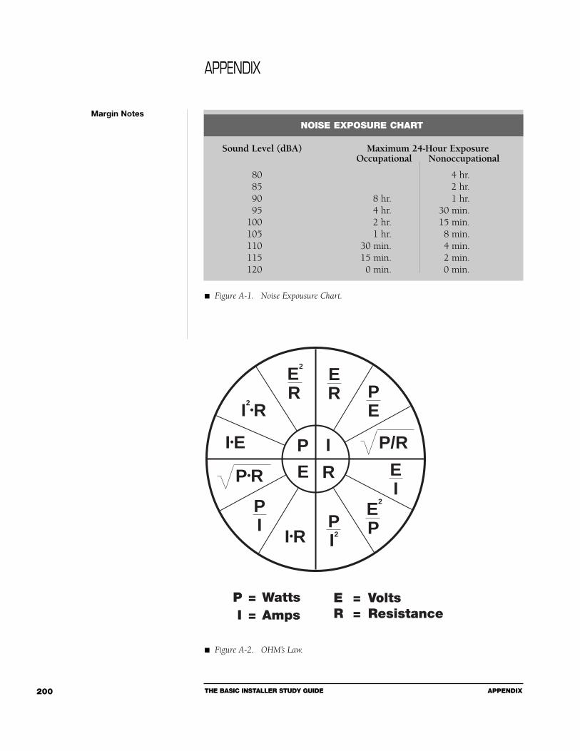
THE BASIC INSTALLER STUDY GUIDE APPENDIX200
Margin Notes
APPENDIX
P I
E R
I•R
PE
PI2
ER
E2
R
PI
EI
E2
P
P•R
I•E
I2•R
P = WattsI = Amps
P/R
E = VoltsR = Resistance
NOISE EXPOSURE CHART
Sound Level (dBA) Maximum 24-Hour ExposureOccupational Nonoccupational
80 4 hr.85 2 hr.90 8 hr. 1 hr.95 4 hr. 30 min.
100 2 hr. 15 min.105 1 hr. 8 min.110 30 min. 4 min.115 15 min. 2 min.120 0 min. 0 min.
Figure A-1. Noise Expousure Chart.
Figure A-2. OHM’s Law.
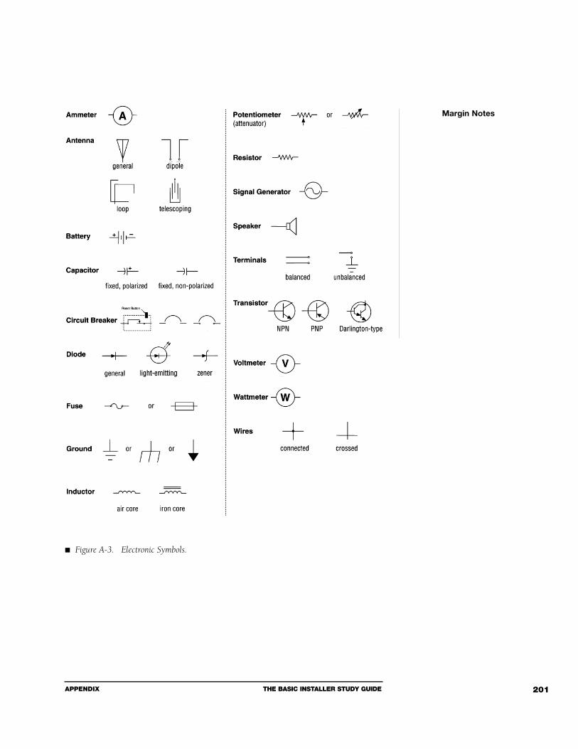
APPENDIX THE BASIC INSTALLER STUDY GUIDE 201
Margin Notes
Figure A-3. Electronic Symbols.
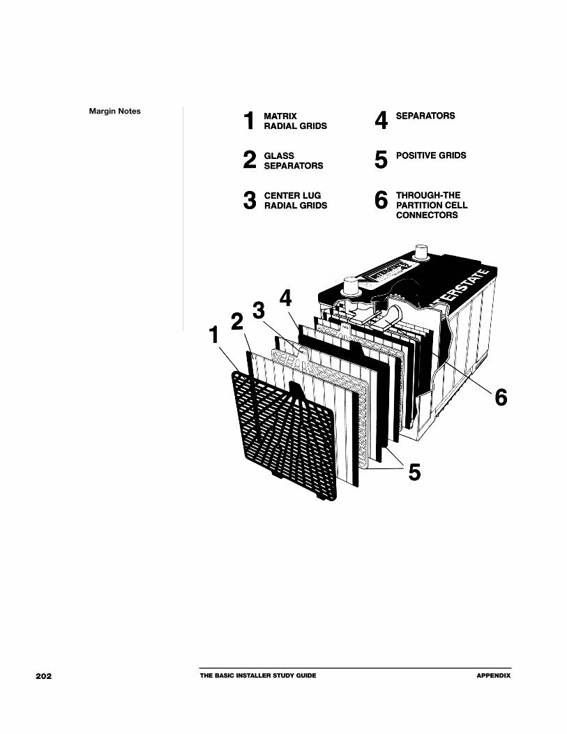
THE BASIC INSTALLER STUDY GUIDE APPENDIX202
Margin Notes
APPENDIX THE BASIC INSTALLER STUDY GUIDE 203
MAGNUSON-MOSS ACT
Have either of these situations happened to you? A customer wants to purchasean aftermarket accessory for his new car, but is concerned because the car dealerhas told him that any accessory (i.e. car alarm, CD player, etc.) not purchased andinstalled by the dealer will void the car’s warranty?
Or the customer has purchased an aftermarket accessory and then returns to yourstore because the dealer has refused to perform warranty work based on the factthat the customer purchased your product, which had nothing to do with theproblem the customer is now experiencing?
It is important for retailers to know their rights under the antitrust laws so theycan assure their customers that any such purchase will in no way affect the war-ranty on their cars.
IT IS A VIOLATION OF FEDERAL ANTITRUST LAWS—
1 For a manufacturer (or its authorized representative) to condition a warrantyon the purchase and use of its own parts or service.
2 For a manufacturer (or its authorized representative) to refuse to honor awarranty unless the manufacturer can show that an aftermarket accessory is thecause of a particular malfunction otherwise covered by the warranty.
KNOW YOUR RIGHTS
For more information, contact Federal Trade Commission at (202) 326-2222 orwrite to the Consumer Electronics Association - Mobile Electronics Division, 2500Wilson Boulevard, Arlington, Virginia 22201-3834.
Margin Notes

THE BASIC INSTALLER STUDY GUIDE APPENDIX204
INSTALLER CHECKOUT SHEET
Customer Name: _______________________________ Phone#: _______________
Vehicle Year: __________________________________ Tag#: _________________
Make: _________________________________ Inspected: Y____ N____
Model: _________________________________
Color: _________________________________ Date: ________________
SYSTEMS
WORKING WORKING Yes No Yes No
Horn ____ ____ Domelight ____ ____Turn Signal ____ ____ Power doorlocks ____ ____Flashers ____ ____ Gauges ____ ____Headlights ____ ____ Brake Lights ____ ____Dashlights ____ ____ Back-up Lights ____ ____Cig Lighter ____ ____ Power Antenna ____ ____Clock ____ ____ _____________ ____ ____Wipers ____ ____ _____________ ____ ____Rear Defroster ____ ____Fan/Heater/AC ____ ____Sun Roof ____ ____Plate Lights ____ ____Elec Windows ____ ____Elec Door Lock ____ ____Elec Seats ____ ____Elec Mirrors ____ ____Elec Sunroof ____ ____Speedometer ____ ____
Comments on Interior: ____________________________________________________
______________________________________________________________________
Comments on Exterior: ____________________________________________________
______________________________________________________________________
Comments on Battery & Cables: ____________________________________________
Installer: ________________________ Date: ______________ Time: _________
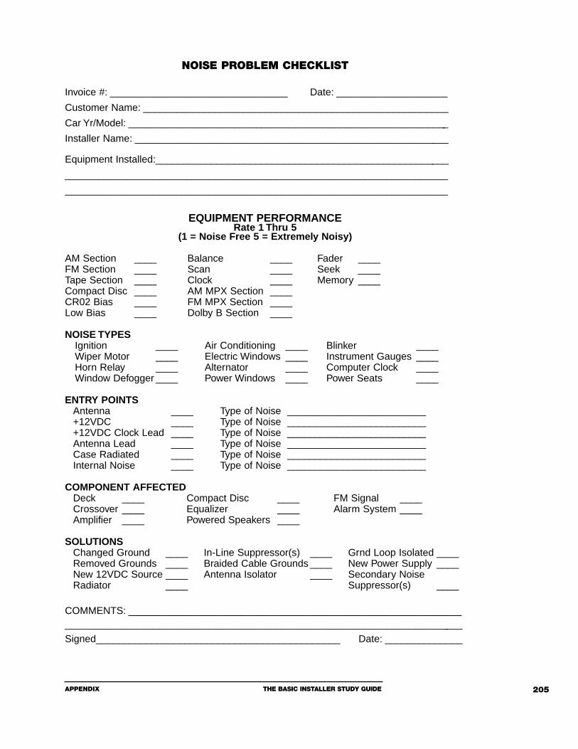
APPENDIX THE BASIC INSTALLER STUDY GUIDE 205
NOISE PROBLEM CHECKLIST
Invoice #: ________________________________ Date: ____________________
Customer Name: _______________________________________________________
Car Yr/Model: __________________________________________________________
Installer Name: _________________________________________________________
Equipment Installed:_____________________________________________________
_____________________________________________________________________
_____________________________________________________________________
EQUIPMENT PERFORMANCERate 1 Thru 5
(1 = Noise Free 5 = Extremely Noisy)
AM Section ____ Balance ____ Fader ____FM Section ____ Scan ____ Seek ____Tape Section ____ Clock ____ Memory ____Compact Disc ____ AM MPX Section ____ CR02 Bias ____ FM MPX Section ____ Low Bias ____ Dolby B Section ____
NOISE TYPESIgnition ____ Air Conditioning ____ Blinker ____Wiper Motor ____ Electric Windows ____ Instrument Gauges ____Horn Relay ____ Alternator ____ Computer Clock ____Window Defogger ____ Power Windows ____ Power Seats ____
ENTRY POINTSAntenna ____ Type of Noise _________________________+12VDC ____ Type of Noise _________________________+12VDC Clock Lead ____ Type of Noise _________________________Antenna Lead ____ Type of Noise _________________________Case Radiated ____ Type of Noise _________________________Internal Noise ____ Type of Noise _________________________
COMPONENT AFFECTEDDeck ____ Compact Disc ____ FM Signal ____Crossover ____ Equalizer ____ Alarm System ____Amplifier ____ Powered Speakers ____
SOLUTIONSChanged Ground ____ In-Line Suppressor(s) ____ Grnd Loop Isolated ____Removed Grounds ____ Braided Cable Grounds ____ New Power Supply ____New 12VDC Source ____ Antenna Isolator ____ Secondary NoiseRadiator ____ Suppressor(s) ____
COMMENTS: ____________________________________________________________________________________________________________________________________
Signed____________________________________________ Date: ______________

THE BASIC INSTALLER STUDY GUIDE REFERENCE MATERIALS206
Alternator Whine, David Navone, Navone Engineering, 4119 Coronado, Suite #4, Stockton, CA 95204; Autosound Technology 2000, (919) 570-0341.
Audio Control Technical Papers 101, 102, 103, Richard Chinn, Audio Control,Lynwood, WA.
Autosound Technology 2000, Tech Briefs, 2112 Westover Terrace, Burlington, NC27215; (919) 570-0341.
Basic Electricity and DC Circuits, Ralph Olivia and Charles Dale, Texas Instruments,1979.
Beat the Book with Fluke Meters, John Fluke Manufacturing Company, 1987,Everett, WA.
Buchsbaum’s Complete Handbook of Practical Electrical Reference Data, Second Edition,W. Buchsbaum, Prentice Hall, 1982.
Building Speaker Systems, G. McComb, Master Publishing, Inc., 1988.
Cellular Installation Handbook, Revised Edition, Bishop and Associates, 2212117th Ave., S.E., Bothell, WA 98021.
Cellular Mobile Radio Telephones, S. Gibson, Prentice Hall, 1987.
Cellular Telephone Installation Handbook, Michael Losee, Quantum Publishing, 1988,Mendocino, CA 95460.
Handbook of Electronic Tables and Formulas, Sixth Edition, Howard W. SamsEngineering Staff, Howard W. Sams and Company, 1988.
High Performance Loudspeakers, Third Edition, Martin Colloms, Pentech Press, 1985.
How to Design and Build Audio Amplifiers, Second Edition, M. Horowitz, Tab BooksInc., 1980.
Loudspeaker Design Cookbook, Vance Dickason; Old Colony Sound Lab, (603) 924-6371.
Margin Notes
REFERENCE MATERIALS

REFERENCE MATERIALS THE BASIC INSTALLER STUDY GUIDE 207
Loudspeaker and Headphone Handbook, John Borwick, Butterworth and Company, 1988.
Musical Acoustics, D. Hall, Wadsworth Inc., 1980.
Noise Control – OSHA, Department of Industrial Relations, State of California#S680, 1986.
Sound Reinforcement Handbook, Gary Davis and Ralph Jones, 1988, Hal LeonardPublishing, 7777 W. Bluemound Road, Milwaukee, WI 53213.
Margin Notes


INDEX
Index

THE BASIC INSTALLER STUDY GUIDE INDEX210
Accessories ......................................................................28, 76, 84, 90, 99, 110Accessory Output Devices......................................................................145, 152Acid..................................................................................................68, 117, 183Air Horns ................................................................................................63, 176Air Pump........................................................................................................176Alarm ..............................................33, 64-65, 72, 88, 100, 123-124, 134, 148,
............................................176, 181, 183, 189-190, 193, 196-197, 203, 205Alarm System ..........................................................64, 123, 176, 181, 197, 205Alternating Current..................26-27, 67, 75, 80, 130, 176-177, 183, 186, 189Alternator Whine ....................................55, 78, 88-89, 97, 123, 125, 176, 206Alternator ................................27, 29, 32, 50, 55-56, 67, 75, 77-78, 80, 88-89,
......................................97, 100, 102-103, 108, 122-123, 125, 176, 205-206American Wire Gauge ..........................................................................36, 91-92Ammeter ........................................................................................100, 103, 176Amperage ..................................................36-37, 51, 54, 64, 69-70, 75, 78, 95,
....................................................98, 103, 105-108, 123, 126, 176, 185, 193Ampere ....................................................................................35, 177, 184, 188Amplifier ................29, 32, 34, 36-38, 44, 47, 49-50, 56-59, 69-70, 72, 77-81,
........ 89, 91, 94, 98, 114, 121, 123, 146, 178, 180, 189-190, 192, 197, 205Amplitude ..........................................26-27, 131, 133, 137-140, 177, 184-185Analog Meters ................................................................................................108Analog Switch ................................................................................................177Anode ................................................................................................72-73, 177Antenna ..................................85-86, 89, 94, 98, 120, 122, 153, 157-162, 164,
............................166, 170, 172-173, 177, 179-181, 190, 194, 196, 204-205Arm................................46, 116, 145, 152, 177, 179, 182, 184, 187, 190, 196Audio ..........................................................26-27, 32, 35-36, 41, 46-47, 55-56,
..............59-60, 70, 75, 78-79, 89, 91, 97-99, 109, 121, 123, 125, 130, 132, ....139, 142-143, 162, 165, 167, 171, 177-178, 181, 184-190, 192-195, 206
Audio Signal............27, 46-47, 60, 79, 130, 142, 171, 177, 185, 190, 193-194Audio System........................................................26, 32, 55-56, 75, 78, 89, 91,
.................................................... 97, 99, 109, 121, 123, 125, 165, 167, 195Autosound Systems ..........................................................................................88
INDEX
A B C
INDEX THE BASIC INSTALLER STUDY GUIDE 211
Bandpass ............................................................................................62, 81, 178Bandpass Filter ..................................................................................62, 81, 178Bass Reflex......................................................................................................178Battery ..........................27-28, 36, 41, 43, 51-52, 55-58, 67-70, 72-73, 75-78,
................................86-88, 90-91, 95, 99-104, 108, 111, 117-118, 120-125, ....................................................154-157, 167, 173, 178-179, 194, 196, 204
Bookkeeping ....................................................................................................85BOSCH ..............................................................................................63-65, 114Bridging..........................................................................................................178
Cable ......................36-38, 42, 44, 58, 62, 68-70, 77-78, 81, 87-89, 91, 94-95, ..........98-99, 101-102, 118, 121-123, 157-159, 162, 166-168, 172-173, 205
Capacitance Glass Tester ................................................................................160Capacitor ................................48-50, 60-61, 67, 79, 81, 99, 171, 179, 183-184Cathode ......................................................................................72-74, 177, 179Cell ..........................................................................................68, 122, 178-179Cellular ....................................................................41, 153, 156-158, 161-162,
..........................................................167, 172, 179, 187, 190-192, 196, 206Cellular System ......................................................................................179, 196Cellular Telephone..........................................156-157, 161, 179, 190-191, 206Channels ..................................................................................................34, 178Chassis ........................52, 55, 69, 72, 89-90, 98, 106, 121, 157, 168-169, 179Chirp......................................................................................................146, 179Circuit ........................................27, 29-31, 33-35, 38-45, 47-48, 51-52, 54-55,
..........57-58, 60, 62, 64-66, 68, 72-73, 77, 80-81, 91, 95-96, 100-101, 107, 120, 142, 148, 151, 155, 176-177, 179-183, 185-187, 189-190, 192, 194-197
Cleaning............................................................................................91, 118-119Clipping ............................................................................8-59, 78-79, 143, 180Closed Circuit ................................................................................................180Coil ......................................38, 42, 50, 58-59, 61-66, 98, 107, 109, 152, 159,
..................................176, 178, 180, 182, 186, 188-189, 191, 195, 197-198Co-linear Antenna ..........................................................................................180Compliance ............................................................................................180, 197Conductors ................................................................................37, 48, 159, 179Connections ..............................................................43, 53, 57, 71, 90, 92, 97,
..................................................................102, 122, 125, 144, 155, 168, 187Constant Output ............................................................................................180Contacts ................................46, 62-66, 95, 147, 152, 154, 171, 182, 189, 195Control Unit ..........................................................145, 158, 178-180, 193, 196Coulomb ..................................................................................................35, 180
THE BASIC INSTALLER STUDY GUIDE INDEX212
Coupling................................................................................158, 160, 182, 186Coupling Box ........................................................................................158, 160Crimping..........................................................................93, 111, 118, 158-159Crossover ............................................39, 44, 47, 49-50, 56, 59-62, 79, 81, 89,
........................................................ 97-98, 114, 123, 180-181, 190-191, 205Current ................................26-36, 38-45, 47-48, 51-52, 54-58, 62-64, 67-69,
....................................71-75, 77-78, 80-81, 91-92, 100-103, 105-109, 111, ............................123, 130, 153, 157, 163-164, 176-189, 191-192, 196-197
Current Draw ........................................................................100-101, 103, 157Current-fed Antenna ......................................................................................181Cutting............................................................................................112-115, 118
Damping ........................................................................................................181Decibel ..........................................................................................116, 133, 181Dedicated Fuse ..............................................................................................181Defogger Lines................................................................................................160Destructive Interference ........................................................136, 138, 171, 181Diaphragm ............................................................130, 176, 181, 186, 191, 195Difference of Potential ........................................................................29-31, 182Digital ........................................................45, 60, 103-104, 108-110, 125-126,
............................................................155, 157, 168-170, 179, 181-183, 196Digital Audiotape (DAT) ................................................................................181Digital Multimeter ....................45, 103-104, 110, 125-126, 155, 168-169, 182DIN ................................................................................................................182Diode....................................................65, 72-74, 152-153, 171, 177, 182, 188Direct Current..............................27-28, 48, 67-68, 75, 80, 106, 108, 178, 181Disassembly......................................................................................................86Dome Light ....................................................................................101, 182, 184Door Lock ..............................................................................................182, 204Drills ..............................................................................................................112Driver ........................................................60, 65, 110, 141, 153-154, 161-165,
..................................................167, 176, 180, 182, 186-188, 191, 193, 197Dynamic Range ..............................................................................143-144, 183
D E F
INDEX THE BASIC INSTALLER STUDY GUIDE 213
Effective Resistance ....................................................................................34, 77Efficiency ......................................................................................102, 116, 183Electrical Laws............................................................................................26, 43Electrical Systems ............................................................................................97Electrolyte ........................................................................................68, 102, 183Electrolytic Capacitor ....................................................................................183Electronic Components ....................................................................................27Electronic Serial Number ..............................................................................183Emergency Override ..............................................................................183, 190EMR Detector ........................................................................................114, 183Enclosure..................................................85, 111, 120, 178, 186-187, 192-193Engine Disable........................................................................145, 150-151, 183
False Alarms ..........................................................................................148, 154FARAD ............................................................................................49, 179, 184Field Disturbance Sensor................................................................................150Filter ............50, 55, 60, 62, 68, 81, 98-100, 121-122, 148, 178-179, 186, 188Fire ..................................................................................44, 118-119, 124, 126Fire Extinguishers ..........................................................................................118First Aid ................................................................................................119, 124Flashing Lights ..............................................................................................184Flat Response..........................................................................138-141, 184, 193Fletcher-Munson Curves, 140, 184FM ....................................................................94, 97, 160, 162, 172, 184, 205Frequency............................26-27, 47-50, 55-56, 60, 62, 79, 94, 97, 114, 122,
............................................130-133, 138-141, 148-149, 151-152, 160-161,
............................................171, 176-181, 183-186, 188, 191-193, 195-196Frequency Counter ........................................................................................184Frequency Response ......................................................138-141, 178, 184-185Fundamental Frequency ........................................................................141, 185Fuse ............................................34, 51-52, 57-58, 77-78, 88, 91, 95, 99, 101,
..........................................103, 106, 121, 123, 126, 157, 179, 181, 185, 197Fusible Link ..................................................................................................185Fusing ..................................................................................................57, 88, 95
THE BASIC INSTALLER STUDY GUIDE INDEX214
Gauges................................................................................37, 91, 155, 204-205Glass................................138-139, 147-148, 152, 158-160, 166, 172-173, 185Glass-Mount Antenna ....................................................................159-160, 190Graphic Equalizer ..........................................................................................140Ground ..........................................................26, 43, 52, 55-56, 58, 60, 65, 69,
......................................77-78, 87, 89-91, 93-95, 97-99, 102, 106, 109, 121,
..................123, 125, 153, 155, 157, 161, 167-169, 172, 176, 181, 185, 205Ground Loop ........................................55-56, 78, 89-90, 97-98, 121, 123, 185Ground Paths ..................................................................................................89Ground Potential ........................................................................................89-90
Hand Nibbler ................................................................................................114Handset ..........................................................................................................157Harmonic ......................................................................................141, 185, 196Head AMP ......................................................................................................114Headroom ......................................................................................143-144, 185Hearing Protection..........................................................................................116Henries ....................................................................................................47, 186Hertz................................................................................27, 131, 149, 176, 185Horns ......................................................................................63, 176, 186, 192Human Hearing ............................................................132-133, 138, 140, 184Hydrometer ....................................................................................102-103, 126
IASCA ............................................................................................37-38, 58, 69Ignition Disables ............................................................................................150Ignition Lead............................................................................................88, 157Ignition Power................................................................................................186Ignition Switch Functions ................................................................................76Impact Sensor ................................................................................172, 186, 191Impedance ..................................................................41, 56, 68, 159, 186, 189Inductive Coupling ........................................................................................186Inductor ....................................................................47, 50, 60-61, 79, 81, 186Infinite Baffle ..................................................................................................187Infrared Sensor ..............................................................................................187
G H I
INDEX THE BASIC INSTALLER STUDY GUIDE 215
Installation ..........................29, 32, 38, 63, 68, 72, 81, 83-126, 130, 144, 152, ....................................154-156, 158, 161-162, 165, 167, 169-170, 191, 206
Interface ................................................................................................153, 165
Joule ..................................................................................................35, 80, 187Jump Starting ................................................................................................157
Landline ........................................................................................................196Lead Dress ........................................................................................................87Leads......................................................46, 58, 71-72, 85, 87-89, 94, 100-101,
....................................105-106, 108-109, 114, 120-121, 123, 125, 137, 182Load Testing ..................................................................................................102Loudspeaker ............................................60, 134-135, 180, 182-183, 187-189,
............................................................................194-195, 197-198, 206-207
Magnet ..........................................................................110, 119, 147, 188, 198Memory..................................................................................................188, 205Meters....................................................................................103, 105, 108, 206MicroFarads......................................................................................................49Microphone ..................................................130, 148, 158, 161-163, 172, 196Mobile Telephone ..........................................................................................196Module ..................................................................................................188, 193Motion Sensor........................................................................................147, 189
Negative Lead ................................................................................105-106, 189Noise ..........................................48, 50, 55-56, 60, 68, 72, 87-91, 94, 96-100,
..........................104, 106, 109, 114, 116-117, 120-123, 125, 139, 141-144, ..................155, 158, 171-172, 176, 182, 186, 189, 192, 194, 200, 205, 207
Noise Sniffers..................................................................................................109Nominal Impedance ..............................................................................186, 189
J K L
M N O
THE BASIC INSTALLER STUDY GUIDE INDEX216
Normally Closed ........................................................................64-66, 147, 189Normally Open ..........................................................................64-66, 147, 189
Occupational Safety and Health Administration............................116, 126, 189Octave ............................................................................61, 141, 171, 189, 191OEM ..............................................................................................65, 75, 77-78Ohm ..........................................................28-36, 38, 40-42, 44, 51, 54-55, 69,
..................................................77-78, 80, 105, 107, 155, 176-177, 189, 200Ohm's Law....................................28-36, 38, 42, 54, 69, 77, 80, 176, 189, 200Open Circuit................................................................................48, 58, 68, 189Oscillator ......................................................................................146, 177, 189Oscilloscope ..........................................................27-28, 59, 97, 111, 168, 180
Pager ..............................................................................................................190Parallel Wiring..........................................................................................42, 190Passive Crossover ..........................................44, 47, 49-50, 60-61, 79, 81, 190Passive Repeater Antenna ..............................................................................190Period..........................................34, 80, 93, 131-132, 150, 153, 176, 185, 191Phase ......................................75, 86-87, 97, 134-138, 154, 171, 180-181, 191Phase Shift..............................................................................................135, 191Pinswitch................................................................................146-147, 191, 196Polarized Capacitors ......................................................................................183Portable Cellular Telephone ..........................................................................191Positive Lead ..................................................................................105-106, 191Potentiometer ..................................................................................46, 171, 191Power ............................26-29, 31-32, 34-38, 41-44, 47, 49-54, 56-60, 62-64,
....................67-70, 74-81, 85, 87-89, 91, 94-95, 98-99, 101, 106, 110-111, ............113-114, 116-117, 119-122, 125, 133, 143, 146, 152-153, 155-157, 160-161, 168, 176, 178-181, 183, 186, 189, 191-192, 194, 197-198, 204-205
Power Cable ............................37, 42, 58, 69, 77, 88, 95, 98-99, 121-122, 157Power Handling................................................................................................51Power Line Noise ..........................................................................................192Power Rating ..............................................................................................51, 78Power Window ............................................................52-53, 63, 152, 192, 205
P Q R
INDEX THE BASIC INSTALLER STUDY GUIDE 217
Power Wiring ......................................................................................76, 78, 91Programming ................................................................................157, 162, 192Pulsed Output........................................................................................172, 192
QTC ..............................................................................................................192
Radar........................................................................28, 149-150, 182, 192, 195Radar Detectors ................................................................................................28Radar Sensor ..................................................................................150, 182, 192Radiated Noise..........................................................87-88, 94, 97-99, 122, 186Radio Frequency Transmitters ........................................................................151Radio Frequency ................................94, 97, 122, 151-152, 160-161, 193, 195Range ....................................56, 62, 101, 103-109, 126, 132-133, 138, 141, 1
..............................43-144, 149, 152, 154, 168-169, 178, 180, 183, 191-193Rarefaction..............................................................................134-135, 181, 193Reassembly ......................................................................................................86Receiver ..................................................149, 156, 163-164, 173, 192-193, 196Reception Problems........................................................................................166Relay......................................................................................62-66, 71, 81, 106,
..........................................................152, 156, 171, 182-183, 193, 195, 205Remote ............................................................ 87, 94, 145, 151-153, 162, 165,
............................................................176, 179-180, 190, 193-194, 196-197Remote Control ............................145, 151, 162, 165, 179, 190, 193, 196-197Remote Control Transmitter ..................................................151, 179, 190, 193Resistance ............................28-35, 37-41, 44-47, 52, 54-57, 63, 68-70, 72-73,
........77, 80-81, 90-91, 93, 105, 107, 123, 177-178, 186, 189, 193-194, 197Resistors ....................................................35, 39-42, 44-45, 60, 74, 77-78, 190Resonance ..............................................................138-139, 171, 181, 184, 193Response ................................138-141, 146, 153-154, 162, 178, 184-185, 193Retriggering ....................................................................................................193Ripple ..............................................55-56, 67-68, 100, 122, 178-179, 192-193
Margin Notes
THE BASIC INSTALLER STUDY GUIDE INDEX218
Safety ..................................13-16, 83, 100, 105, 113, 115-118, 126, 153, 189Saws................................................................................................112-113, 116Seat Sensor ....................................................................................................194Security ..........................................................................28, 41, 46, 63, 76, 106,
....................................................126, 129-173, 176-180, 182-188, 190-198Security System ........................................................63, 76, 106, 126, 144-146,
............................................151-156, 172, 176-180, 182-187, 190, 192-198Semiconductors ..........................................................................................71-72Sensitivity ..........................................................................44, 46, 107, 148, 194Sensors ....................63, 145, 147-150, 164, 168, 185, 187, 189, 191, 194-195Shock Sensor..........................................................................................148, 194Short Circuit ..........................................................57-58, 77, 96, 107, 179, 194Signal-to-Noise ..............................................................................................194Single Pole Double Throw ..............................................................65, 152, 195Single Pole Single Throw ......................................................................152, 195Sirens ......................................................................................63, 146, 156, 180Slope ........................................................................................................61, 179Solder ........................................................................92-93, 110, 117, 122, 144Sound ......................................35, 49, 56, 79-81, 116, 126, 129-135, 137-141,
............................................143-144, 146, 148-149, 171, 176-178, 181-183, ............................................185-188, 190-191, 193-195, 198, 200, 206-207
Sound Discriminator ..............................................................................148, 195Sound Pressure Level ............................................................................133, 195Sound Wave ..................130-132, 134, 149, 171, 176-178, 191, 193, 195, 198Sources ......................................................................................87, 98, 134, 155Spatial Sensors........................................................................149-150, 187, 195Speaker ..........38, 41-42, 44, 47, 57-58, 60, 69-70, 77-79, 81, 85, 87-88, 104,
..................106-107, 111, 113-115, 120-121, 123, 125, 130, 135-139, 141,
..........146, 158, 161, 165, 180-182, 184, 186-190, 192, 194, 197-198, 206Spider ............................................................................................................195Staging............................................................................................................195Starter Disable ........................................................................................150, 195Starter Interrupt..............................................................................................151Stiffening Capacitor ..........................................................................................50Subwoofer ..........................................................................42, 47, 79, 142, 195Sulfuric Acid ....................................................................................68, 117, 183
Margin Notes S T U
INDEX THE BASIC INSTALLER STUDY GUIDE 219
Switch ........................41, 52, 58, 62-64, 71, 74, 76, 79, 88, 91, 105-107, 123, 145-147, 152, 168-171, 177-178, 183-184, 186, 189-191, 193-194, 196-197
Switch Triggers ..............................................................................145-146, 171System Design ..................................................................................................44
Telephones ....................................................................156, 158, 191-192, 206Test Equipment ........................................................................................97, 103Test Lights ..............................................................................................109, 155Time Alignment..............................................................................................137Tools..............................................................85-86, 97, 109, 111-113, 115-119Tracking System ............................................................................................153Transceiver..............................................................................156-157, 179, 196Transfer Function ..........................................................................................196Transmission Line ..........................................................................................181Transmitter ............................................151-152, 156, 176, 179, 190, 193, 196Trigger................................................................64-65, 112, 146, 148-149, 176,
............................................................180-181, 186-187, 189, 193, 195-198Troubleshooting ............................................................................26, 45-46, 52,
................................................................77, 96-97, 100, 103, 119, 146, 155Trunk Release ................................................................................................197Tweeter ................................................48-49, 51, 59-61, 78, 81, 141, 180, 197
Ultrasonic Sensor ..................................................................................149, 197Universal Timers ............................................................................................153
Vehicle ..........................................27-29, 36, 52, 55, 57, 65, 67, 69-70, 75-77, ............84-92, 94, 98-99, 101-102, 104, 106, 109, 115, 118-122, 125, 139, ............142, 144, 146-157, 161-164, 166-171, 173, 176-179, 181-198, 204
Voice Coil ..............38, 42, 58-59, 107, 176, 182, 186, 189, 191, 195, 197-198Volt ..................................................................34-35, 37, 42, 55-56, 58-59, 65,
....................................................70, 73, 77, 80-81, 104, 107, 177, 184, 197
Margin Notes
V W X Y Z

THE BASIC INSTALLER STUDY GUIDE INDEX220
Voltage......................................27-34, 36, 38-40, 42-44, 46, 48, 50, 52, 54-59, ..........................63-65, 67-70, 72-78, 80-81, 89, 97-98, 100, 103, 105-109, ..........................114, 121, 123, 133, 153, 157, 159, 168-169, 173, 176-178, ............................................................181-182, 184-185, 187, 189-192, 197
Voltage Drop ................................32, 42-43, 52, 54, 56, 69-70, 74, 77, 89, 197Volt-Ohm-Meter ....................................................................................189, 197Volts ....................................................29, 32-35, 38, 50, 54, 57, 59, 68, 73-74,
................................................80-81, 102-106, 108, 161, 168-170, 179, 189
Watt ............................................................34-36, 80, 113, 157, 187, 194, 198Wattage................................................................................32, 36, 44, 113, 198Wavelength ......................................................................94, 131-132, 137, 198Wire ..................................26, 29, 32, 34, 36-38, 43, 47, 51, 53, 56-57, 69-70,
....................76-77, 80, 85, 87-93, 95, 98-99, 101, 106, 110, 118, 120-125, ....137, 147, 155-157, 162, 168-169, 177-178, 180, 185-187, 190-191, 197
Wire Gauge ..................................................................26, 36-38, 43, 77, 91-92Woofer..................................................................................60-61, 81, 137, 198
Xmax ..............................................................................................................198
ZONE ............................................................................................................198
Margin Notes