mechanics of individual nanostructures (an...
TRANSCRIPT

Northwestern University Rod Ruoff Nanotechnology
Mechanics of Individual Nanostructures (an overview)
Northwestern University Rod Ruoff Nanotechnology
Outline
1. Introduction
2. Tensile Test
3. Resonance Test
4. Other methods

Northwestern University Rod Ruoff Nanotechnology
Part One:
Introduction
Northwestern University Rod Ruoff Nanotechnology
1-D NanostructuresIn recent years various one-dimensional (1-D) nanostructures have been synthesized. A full understanding of their mechanical properties is important for applications of these novel materials.
(a) Scanning Electron Microscope (SEM) image of crystalline boron nanowires on alumina substrate
(a)(b)
(b) Transmission Electron Microscope (TEM) image of a crystalline boron nanowire

Northwestern University Rod Ruoff Nanotechnology
1-D Nanostructures (con’t)
TEM image of a multi-wall carbon nanotube
SEM image of arc-grown MWCNTs from MER Corp. AZ.
Single-wall carbon nanotube (SWCNT) Multi-wall carbon nanotube (MWCNT)
http://physicsweb.org/articles/world/11/1/9/1/world-11-1-9-1
Northwestern University Rod Ruoff Nanotechnology
Part Two:
Nanoscale Tensile Test

Northwestern University Rod Ruoff Nanotechnology
Tensile stretching of individual MWCNTWe will continue to study the mechanical properties for MWCNTs with our nano-manipulator.
Yu MF, Lourie O, Dyer MJ, Moloni K, Kelly TF, and Ruoff RS, Strength and breaking mechanism of multiwalled carbon nanotubes under tensile load, SCIENCE, 287, 637-640 (2000).
Mechanical tensile testing schematic SEM images of tensile test
Northwestern University Rod Ruoff Nanotechnology
Tensile Test on PEO Nanofiber
E.P.S. Tan, C.N. Goh, C.H. Sow, and C.T. Lim, Tensile Test of a Single Nanofiber Using an Atomic Force Microscope Tip. Appl. Phys. Lett., 2005.86(6).
Schematic diagram of the tensile test of the nanofiber using a piezoresistive AFM tip.
A single electrospun polyethylene oxide (PEO) nanofiber is stretched with AFM cantilever tip with a micromanipulator.

Northwestern University Rod Ruoff Nanotechnology
Result
(left) single fiber manipulation
(top) tensile test result
E.P.S. Tan, C.N. Goh, C.H. Sow, and C.T. Lim, Tensile Test of a Single Nanofiber Using an Atomic Force Microscope Tip. Appl. Phys. Lett., 2005.86(6).
Northwestern University Rod Ruoff Nanotechnology
(a) The same nanocoil is clamped between two AFM cantilevers. The left cantilever is stiffer than the right cantilever. (b) the relaxed nanocoil. (c) the nanocoil at a relative elongation of 20 %. (d) the nanocoil at a relative elongation of 33 %.

Northwestern University Rod Ruoff Nanotechnology
Boron Nanowire: Tensile TestIndividual crystalline boron nanowire was tensile loaded with two AFM cantilevers inside SEM.
Northwestern University Rod Ruoff Nanotechnology
MWCNT: Sword-in-sheath FractureMulti-wall carbon nanotubes fracture in a “sword-in-sheath” manner during tensile test. Outer shellInner shells
Inner shells
outer shell
SEM images of sword-in-sheath fracture of a MWCNT under tension

Northwestern University Rod Ruoff Nanotechnology
Northwestern University Rod Ruoff Nanotechnology
Part Three:
Nanoscale Resonance Test

Northwestern University Rod Ruoff Nanotechnology
Mechanical Resonance: Carbon Nanotube
Poncharal,P., et al, Science, 283, 1513-1516 (1999)
(top) Elastic properties of nanotubes
(left) Electromechanical vibration of a MWCNT (A) thermal vibration (B) Fundamental resonance (C) First overtone resonance
Northwestern University Rod Ruoff Nanotechnology
Mechanical Resonance: DLC Pillar
Fujita,J. et al, J.Vac.Sci.Technol. B 19(6), 2834-2836 (2001)
SEM image of the vibration Schematic of mechanical vibration experimental setup

Northwestern University Rod Ruoff Nanotechnology
Mechanical Resonance: ZnO Nanobelt
Bai et al, App. Phys. Lett. 82(26) 4806-4808 (2003)
Northwestern University Rod Ruoff Nanotechnology
Mechanical Resonance: ZnO nanobelt (con’t)

Northwestern University Rod Ruoff Nanotechnology
SiO2 Nanowire: Source
Ultrasonically dispersed SiO2nanowire
Synthesized by Z.W. Pan (J.Am.Chem.Soc.’02)
TEM image (inserts: High resolution image and diffraction pattern)
Northwestern University Rod Ruoff Nanotechnology
SiO2 Nanowire: Mechanical Resonance
Electrical Excitation Mechanical Excitation
W wireW wire
W wire (counter electrode)
D. A. Dikin, X. Chen, W. Ding, G. Wagner, R. S. Ruoff, Resonance vibration of amorphous SiO2 nanowires driven by mechanical or electrical field excitation, Journal of Applied Physics 93, 226 (2003).
Northwestern University Rod Ruoff Nanotechnology
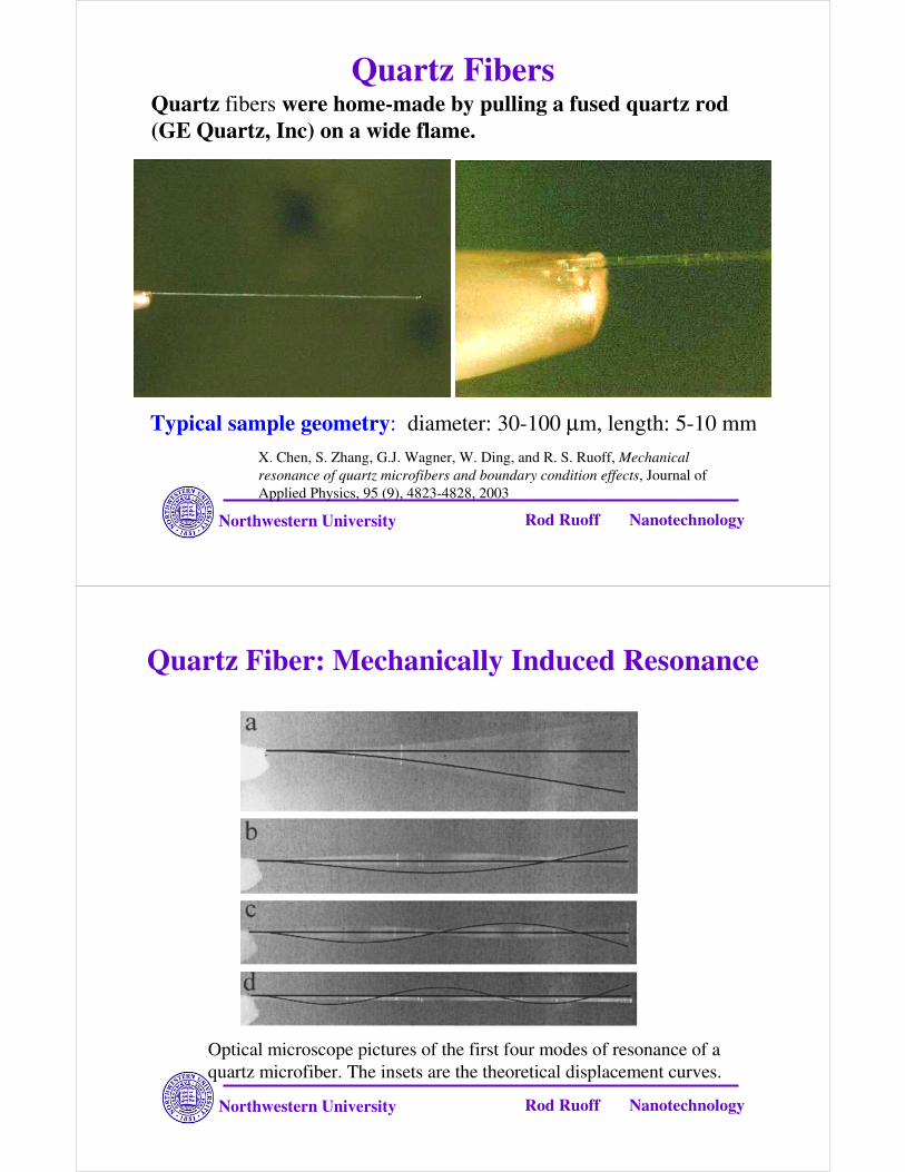
Quartz Fibers
Typical sample geometry: diameter: 30-100 µm, length: 5-10 mm
Quartz fibers were home-made by pulling a fused quartz rod (GE Quartz, Inc) on a wide flame.
X. Chen, S. Zhang, G.J. Wagner, W. Ding, and R. S. Ruoff, Mechanical resonance of quartz microfibers and boundary condition effects, Journal of Applied Physics, 95 (9), 4823-4828, 2003
Northwestern University Rod Ruoff Nanotechnology
Quartz Fiber: Mechanically Induced Resonance
Optical microscope pictures of the first four modes of resonance of a quartz microfiber. The insets are the theoretical displacement curves.
Northwestern University Rod Ruoff Nanotechnology
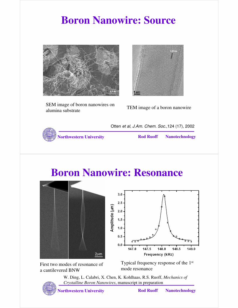
Boron Nanowire: Source
SEM image of boron nanowires on alumina substrate TEM image of a boron nanowire
Otten et al, J.Am. Chem. Soc.,124 (17), 2002
Northwestern University Rod Ruoff Nanotechnology
Boron Nanowire: Resonance
First two modes of resonance of a cantilevered BNW
Typical frequency response of the 1st
mode resonance
W. Ding, L. Calabri, X. Chen, K. Kohlhaas, R.S. Ruoff, Mechanics of Crystalline Boron Nanowires, manuscript in preparation

Northwestern University Rod Ruoff Nanotechnology
Part Four:
Other Methods
Northwestern University Rod Ruoff Nanotechnology
MWCNTs were pinned at one end to molyneenum disulfide surface. AFM tip was used to bend the nanotube. The bending force was measured versus displacements along the unpinned length.
Eric E. Wong et al, Nanobeams Mechanics: Elasticity, Strength,asnd Toughness of Nanorods and Nanotubes, Science, Vol 277,1997
Elasticity, Strength, and Toughness of Nanobeam

Northwestern University Rod Ruoff Nanotechnology
Con’t
Images of a 4.4-nm-diameter MWNT before and after bending on an oxidized silicon substrate
Calculation model used to determine the mechanical property of MWNTs.
Schematic of a pinned beam with a free end. The beam of length L is subjected to a point load P at x = aand to a distributed friction force f.
Eric E. Wong et al, Nanobeams Mechanics: Elasticity, Strength,asnd Toughness of Nanorods and Nanotubes, Science, Vol 277,1997
Northwestern University Rod Ruoff Nanotechnology
AFM Three-point Bend Test
E.P.S. Tan and C.T. Lim, Physical properties of a single polymeric nanofiber.Appl. Phys. Lett., 2004. 84(9): 1603-1605.

Northwestern University Rod Ruoff Nanotechnology
Nanoindentation of Nanowire
Li, XD, Gao, HS, Murphy, C.J, Caswell, K.K, Nanoindentation of Silver Nanowires, Nano Letter, 2003, 3(11) 1495-1498
AFM image of a nanowire AFM image of indents on a nanowire
Hardness and elastic modulus of a silver nanowire were directly measured with a nanoindenter.
Northwestern University Rod Ruoff Nanotechnology
M. F. Yu, B. I. Yakobson and R. S. Ruoff, Controlled sliding and pullout of nested shells in individual multiwalled carbon nanotubes, J. Phys. Chem., B, 104, 8764-8767 (2000).
Controlled Sliding and Pullout

Northwestern University Rod Ruoff Nanotechnology
Low-Friction Nanoscale Bearing from MWCNT
Schematic Representation:
A. A MWCNT mounted on stage.
B. Open the end of the MWCNT.
C. Attach the nanomanipulator to the core tube.
D. The core tube was repeatedly telescoped and observe wear.
E. The core was released and pulled back into outside-shell by van de Waals force.
John Cumings et al ,Low-Friction Nanoscale Liner Bearing Realized from MECNT, Science, Vol 289, July 2000
Northwestern University Rod Ruoff Nanotechnology
The repeat extension and retraction of nanotube segments revealed no wear or fatigue on atomic scale.
It’s possible to construct wear-free surfaces by nanotubes
(left top)TEM image of a telescoped nanotube
(left bottom) TEM image of a bamboo section of a MWCNT.The core tubes on the right was telescoped outward.
Con’t
John Cumings et al ,Low-Friction Nanoscale Liner Bearing Realized from MECNT, Science, Vol 289, July 2000

Northwestern University Rod Ruoff Nanotechnology
Poncharal et al, Electrostatic Deflections and Electromechanical Resonances of Carbon nanotubes, Science, Vol 283, 1999
(a) Uncharged Nanotube
(b) Charged nanotube.
Electromechanical Resonance of MWCNT
Electrostatic potential field was used to deflected the carbon nanotube.The measured deflection ofnanotube was proportional to the square of static potential.
Northwestern University Rod Ruoff Nanotechnology
Schematic Illustration of the Project
Fixed end
Actuator—the moving component, integrated with force sensor
10-10 SWCNT, MWCNT, nanowire, or other nanomaterials
direct imaging to measure ∆∆∆∆x
Anchor
Anchor
Electrode
Electrode
fixed
Side view of the design
Handling layer—Si or Pyrex glass
Anchor, dielectric material—SiO2
Electrodes Actuating and sensing components
Shaoning Lu*

Northwestern University Rod Ruoff Nanotechnology
Thermally Actuated Testing Stage
Device ready to test
Si device
Carbon tape
Copper electrodes
Connection to power source
Shaoning Lu, Dmitry Dikin,Junghoon Lee, Rodney S. Ruoff, Rev. of Sci. Instruments, accepted