mechanical testing of heterogeneous energy …
TRANSCRIPT
JET 35
JET Volume 11 (2018) p.p. 35-48Issue 1, May 2018
Type of article 1.01www.fe.um.si/en/jet.html
MECHANICAL TESTING OF HETEROGENEOUS ENERGY
COMPONENTS
MEHANSKO PREIZKUŠANJE HETEROGENIH ENERGETSKIH
COMPONENTTadej PavlinR
Keywords: fracture toughness, crack-tip opening displacement (CTOD), CTOD fracture toughness testing, CTOD-R resistance curve, heterogeneous joint
AbstractWelding of a high-strength low-alloyed (HSLA) steel with the aim to produce an under-matched weld joint presents a technological challenge for modern welded structure production. Attention should be paid to the level of strength mismatching, which should provide sufficient toughness of the weld metal by using an appropriate welding consumable (wire, electrode) and welding procedure. High toughness of weld metal is necessary to enable local plastic deformation and to prevent brittle frac-ture. It is of utmost importance to exclude the possibility of plane faults (hydrogen cracking, lack of fusion, etc.) and local-brittle-zone (LBZ) appearance in HSLA steel under-matched welded joints, which can cause failure.
This research aimed to estimate the weld metal Crack Tip Opening Displacement (CTOD) fracture toughness using standard procedures for three differently under-matched welded joints.
R Corresponding author: Ph.D. Student, Tadej Pavlin, Faculty of Energy Technology, University of Maribor, Tel.: +386 (0)3-7770-400, Mailing address: Koroška cesta 62a, Velenje, Slovenia, E-mail address: [email protected]
36 JET
JET Vol. 11 (2018)Issue 1
Tadej Pavlin2 Tadej Pavlin JET Vol. 11 (2018) Issue 1
‐‐‐‐‐‐‐‐‐‐
Povzetek Varjenje visokokakovostnega nizko legiranega jekla (HSLA) z namenom izdelave nizkotrdnostnega zvarnega spoja predstavlja tehnološki izziv za moderno izdelavo varjene konstrukcije. Pri tem moramo upoštevati stopnjo trdnostne neenakosti, ki naj bi zagotovila zadostno žilavost jeklenega zvara z uporabo ustrezne varilne žice (žice, elektrode) in postopka varjenja. Visoka žilavost jeklenega zvara je potrebna, da se omogoči lokalna plastična deformacija in prepreči krhki lom. Zelo pomembno je, da se izključi možnost ravninskih napak (vodikova razpokljivost, pomanjkanje fuzije itd.) in oblika lokalnega krhkega območja (LBZ) v visokotrdnostnih (HSLA) jeklenih zvarih, kar lahko povzroči zlom. Namen te raziskave je bil oceniti lomno žilavost jeklenih zvarov s CTOD preizkušanjem za tri različne nizkotrdnostne zvarne spoje.
1 INTRODUCTION
Welding of a high‐strength low‐alloyed (HSLA) steel to produce an under‐matched weld joint presents a technological challenge for current welded structure production. When the yield strength is lower in weld metal than in base metal, the welded joint is under‐matched. The strength mismatch factor (M) is defined as the ratio of weld‐metal to base‐metal yield strengths so that M < 1 defines an under‐matched welded joint. Under‐matched welded joints are used for the repair welding of joints damaged during hard hydrogen cracking without pre‐heating, especially for welded joints made of HSLA steels operation conditions or by short period overloading. They are also recommended to prevent cold cracking with yield strength above 700 MPa. Specifically, HSLA steels usually require pre‐heating if matching or overmatching welding consumable is used, which is not only expensive but also needs a carefully designed and strictly followed welding procedure. Finally, there is a frequent need for additional thermal or mechanical treatment afterwards.
One should pay attention to the level of strength mismatching, which should provide sufficient toughness of the weld metal by using an appropriate welding consumable (wire, electrode) and welding procedure. The high toughness of weld metal is necessary to enable local plastic deformation and to prevent brittle fracture. It is of utmost importance to exclude the possibility of plane faults (hydrogen cracking, lack of fusion, etc.) and local‐brittle‐zone (LBZ) appearance in HSLA steel under‐matched welded joints, which can cause failure, [1‐7].
This research aimed at estimating the weld metal CTOD fracture toughness for three differently under‐matched welded joints.
2 MATERIALS AND MECHANICAL PROPERTIES
High‐strength low‐alloyed (HSLA) steel in a quenched and tempered condition, corresponding to the grade HT 80, was used. The Fluxo Cored Arc Welding process (FCAW) was used, and two different tubular wires were selected. Three different types of global under‐matched welded joint were produced: one homogeneous and two heterogeneous. The homogeneous welded joint was made with pre‐heating and post‐heating of the base material, entirely with the same consumable (wire WELTEC B 575). Two different types of heterogeneous welded joints were made using a softer consumable (wire WELTEC B 370) for the soft root layer (one with two and the other with four passes) in order to avoid pre‐heating of the base material and to prevent cold cracking. The

JET 37
Mechanical testing of heterogeneous energy components Mechanical testing of heterogeneous energy components 3
‐‐‐‐‐‐‐‐‐‐
filler passes were made with the wire WELTEC B 575 as well as the cap passes. Chemical compositions of the base metal and all‐weld metals are given in Table 2.1.
Weld metal mechanical properties were determined by round tensile specimens extracted from the root and the filler region of X‐groove welds in the weld direction. The expected mechanical properties of homogeneous and heterogeneous under‐matched welded joints have not been reached neither in the filler region nor in the root region, as shown in Tables 2.2 and 3.1. The cause was weld metal alloying with elements from the diluted base metal.
The alloying effect was more pronounced in the root region than in the filler region, and it was also the main reason for local strength mismatch appearing in the thickness and direction of homogeneous and heterogeneous welds (see chemical analysis given in Tables 2.1. and 3.1.).
Table 2.1: Chemical composition of base material and all‐weld metals Chemical composition [%]
C Si Mn P S Cr Ni Mo Cu Al
HT 80 0.16 0.68 0.75 0.020 0.003 0.79 0.09 0.032 0.24 0.037 WELTEC B 575 0.05 0.04 1.52 0.011 0.008 0.08 1.45 0.66 ‐ ‐ WELTEC B 370 soft root 0.05 0.25 0.61 0.011 0.008 0.06 0.07 0.03 ‐ ‐
Table 2.2:Mechanical properties of base material and all‐weld metals
Designation Rp [MPa] Rm [MPa] Elongation [%]
Charpy toughness [J] Expected M
HT 80 710 810 15.5 85, 91, 100at 0 °C ‐
WELTEC B 575 542 591 23 47, 70, 71at ‐40 °C 0.76
WELTEC B 370 soroot 403 466 32 100, 215, 145
at ‐40 °C 0.56
Bearing in mind the values of strength mismatch factors M in Table 3.1, one can see that the root inhomogeneous weld metal is overmatched (M = 1.05 => 5% overmatching), which leads to strongly increased cold‐cracking susceptibility, whereas the filler region has practically the same strength as the base material (M = 0.99). This effect proves the concept of heterogeneous weld in an under‐matched joint with two‐pass (M = 0.81 => 19% undermatching) or four‐pass (M = 0.91 => 9% undermatching) soft root layer in order to prevent cold cracking without pre‐heating of the base material. 3 EXPERIMENTAL PROCEDURE
The set of B × B specimens was taken from under‐matched homogeneous and heterogeneous welds to obtain fracture behaviour of welded joints with defects like cold cracks and lack of fusion, which often exist in real welded joints. With CTOD testing of welded joints, they are treated as
38 JET
JET Vol. 11 (2018)Issue 1
Tadej Pavlin4 Tadej Pavlin JET Vol. 11 (2018) Issue 1
‐‐‐‐‐‐‐‐‐‐
planar (plane) faults. Thus, in the CTOD specimen, the surface cracks with different depths were positioned in weld metal with the aim of locating the fatigue‐crack‐tip front in different microstructure regions of mismatched welded joints and of analysing the material behaviour at the crack tip in regard to the nearby microstructure influence.
Fracture toughness of homogeneous and heterogeneous under‐matched welded joints was evaluated using the standard static CTOD test at GKSS Research Center Geesthacht in Germany, [2]. Specimen loading was carried out with constant crosshead speed v = 0.5 mm/min. The test temperature was ‐10 °C according to the recommendation of the OMAE (Offshore Mechanics and Arctic Engineering) association. For CTOD testing, the single specimen method was used by BS 7448, [1]. To evaluate fracture toughness of under‐matched welded joints, standard single‐edge notched‐bend (SENB) specimens (B × B, B = 36 mm) with surface notches in the weld metal were used, as shown in Table 3.2.
The B × B specimens were fatigue pre‐cracked from the surface to a distinct welded joint microstructure.
Table 3.1: Mechanical properties and chemical composition of homogeneous and heterogeneous under‐matched weld joints
Designation Rp [MPa] Rm [MPa] Elongation [%]
Charpy V [J] at ‐10 °C
Expected M
Achieved M
Base material HT 80 693 830 19.6 79, 78, 64 ‐ ‐
Heterogeneous weld joint – filler material WELTEC B 575 WM – cap 687 804 22.3 110, 104, 102 0.76 0.99 WM – root 730 803 21.8 72, 38, 50 0.76 1.05
Heterogeneous weld joint –filler material WELTEC B 370 in the root (the rest WELTEC B 575)
WM – 2 x soft root passes
567 625 19.7 ‐ 0.56 at the root
0.81 at the root
WM – 4 x soft root passes
631 673 21.9 35, 17, 34 0.56 at the root
0.91 at the root
Composition [%]
C Si Mn P S Cr Ni Mo Cu Al, Ti, Nb
WM hom. – cap 0.04 0.44 1.48 0.009 0.003 0.12 1.63 0.49 0.12 ‐
WM hom. – root 0.10 0.33 0.89 0.011 0.008 0.73 1.11 0.42 0.13 ‐
WM – 2 x soft passes 0.12 0.41 0.78 0.011 0.006 0.40 0.10 0.17 0.16 ‐
WM – 4 x soft passes 0.10 0.33 0.78 0.012 0.007 0.24 0.13 0.11 0.13 ‐

JET 39
Mechanical testing of heterogeneous energy components Mechanical testing of heterogeneous energy components 5
‐‐‐‐‐‐‐‐‐‐
Table 3.2: Fatigue crack positioning in SENB specimens (B x B) at under‐matched weld joints
Weld groovewidth 2H (at the crack tip)
Fatigue crack position
Crack depth [a/ W]
2H = 14.1 mm ̴ 0.25
2H = 13.9 mm ̴ 0.25
2H = 6.8 mm ̴ 0.48
2H = 7.4 mm ̴ 0.43
For all specimens, the fatigue pre‐cracking was carried out with the GKSS Step‐Wise High R ratio method (SHR) procedure. During the CTOD tests, the DC potential drop technique was used for stable crack‐growth monitoring. The load line displacement (LLD) was also measured with a reference bar to minimize the effects of possible indentations of the rollers. The CTOD values were directly measured by specially developed δ5 clip gauge (Figure 3.1.) on the specimen side surfaces at the fatigue crack tip over a gauge length of 5 mm.
3.1 Fractographic and metallographic examinations
To determine the influence of crack‐tip microstructure on fracture behaviour, the metallographic and fractographic examinations were performed. For fractographic examinations, the Scanning Electronic Microscope (SEM) was used, while the metallographic investigations were performed by the Optical Light Microscope. After fractographic examinations, the specimens were cut in crack‐growth direction and polished and etched with 3% Nital.
40 JET
JET Vol. 11 (2018)Issue 1
Tadej Pavlin6 Tadej Pavlin JET Vol. 11 (2018) Issue 1
‐‐‐‐‐‐‐‐‐‐
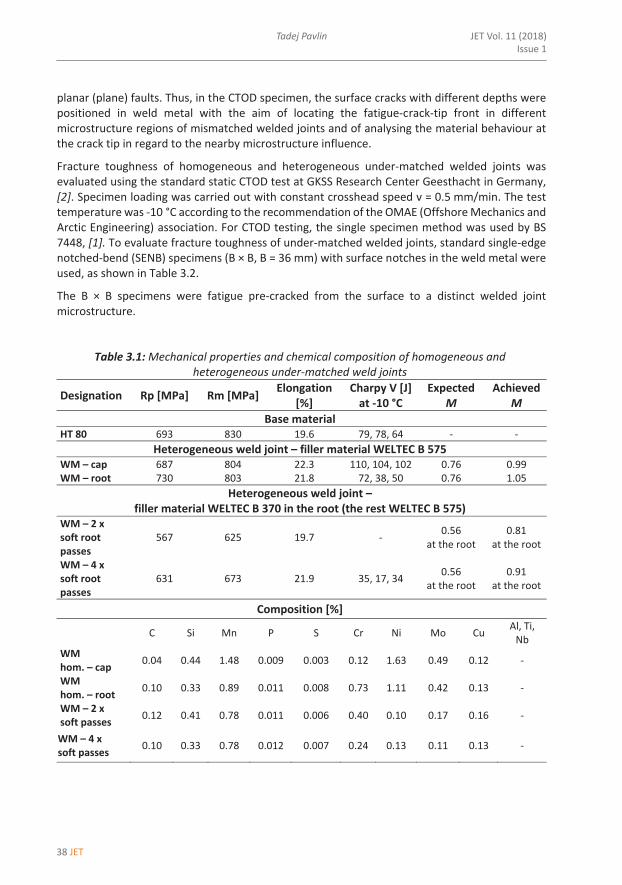
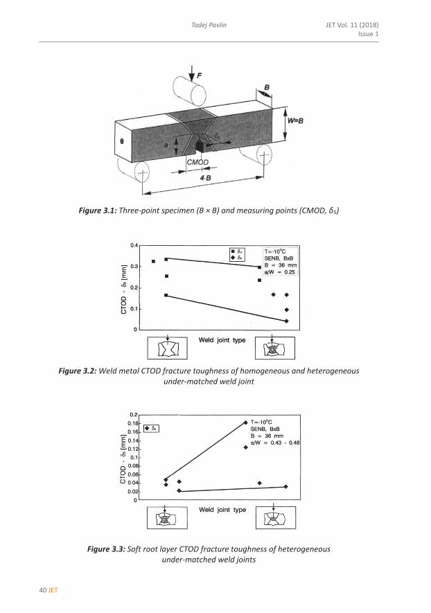
Figure 3.1: Three‐point specimen (B × B) and measuring points (CMOD, δ5)
Figure 3.2: Weld metal CTOD fracture toughness of homogeneous and heterogeneous
under‐matched weld joint
Figure 3.3: Soft root layer CTOD fracture toughness of heterogeneous under‐matched weld joints
JET 41
Mechanical testing of heterogeneous energy components Mechanical testing of heterogeneous energy components 7
‐‐‐‐‐‐‐‐‐‐
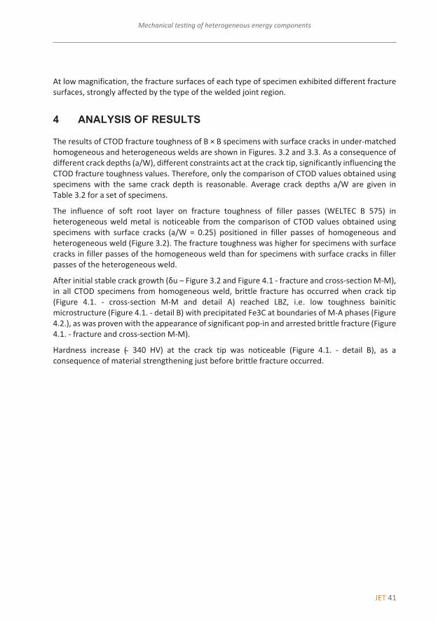
At low magnification, the fracture surfaces of each type of specimen exhibited different fracture surfaces, strongly affected by the type of the welded joint region.
4 ANALYSIS OF RESULTS
The results of CTOD fracture toughness of B × B specimens with surface cracks in under‐matched homogeneous and heterogeneous welds are shown in Figures. 3.2 and 3.3. As a consequence of different crack depths (a/W), different constraints act at the crack tip, significantly influencing the CTOD fracture toughness values. Therefore, only the comparison of CTOD values obtained using specimens with the same crack depth is reasonable. Average crack depths a/W are given in Table 3.2 for a set of specimens.
The influence of soft root layer on fracture toughness of filler passes (WELTEC B 575) in heterogeneous weld metal is noticeable from the comparison of CTOD values obtained using specimens with surface cracks (a/W = 0.25) positioned in filler passes of homogeneous and heterogeneous weld (Figure 3.2). The fracture toughness was higher for specimens with surface cracks in filler passes of the homogeneous weld than for specimens with surface cracks in filler passes of the heterogeneous weld.
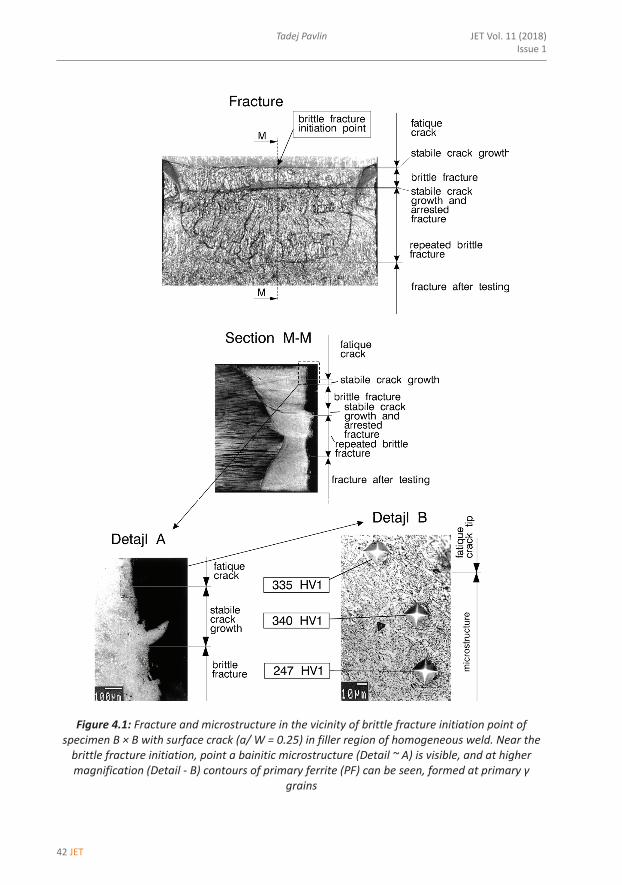
After initial stable crack growth (δu – Figure 3.2 and Figure 4.1 ‐ fracture and cross‐section M‐M), in all CTOD specimens from homogeneous weld, brittle fracture has occurred when crack tip (Figure 4.1. ‐ cross‐section M‐M and detail A) reached LBZ, i.e. low toughness bainitic microstructure (Figure 4.1. ‐ detail B) with precipitated Fe3C at boundaries of M‐A phases (Figure 4.2.), as was proven with the appearance of significant pop‐in and arrested brittle fracture (Figure 4.1. ‐ fracture and cross‐section M‐M).
Hardness increase ( ̴ 340 HV) at the crack tip was noticeable (Figure 4.1. ‐ detail B), as a consequence of material strengthening just before brittle fracture occurred.
42 JET
JET Vol. 11 (2018)Issue 1
Tadej Pavlin8 Tadej Pavlin JET Vol. 11 (2018) Issue 1
‐‐‐‐‐‐‐‐‐‐
Figure 4.1: Fracture and microstructure in the vicinity of brittle fracture initiation point of specimen B × B with surface crack (a/ W = 0.25) in filler region of homogeneous weld. Near the brittle fracture initiation, point a bainitic microstructure (Detail ~ A) is visible, and at higher magnification (Detail ‐ B) contours of primary ferrite (PF) can be seen, formed at primary γ
grains
JET 43
Mechanical testing of heterogeneous energy components Mechanical testing of heterogeneous energy components 9
‐‐‐‐‐‐‐‐‐‐
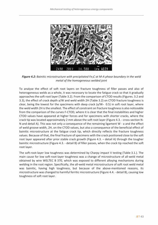
Figure 4.2: Bainitic microstructure with precipitated Fe3C at M‐A phase boundary in the weld metal of the homogeneous welded joint
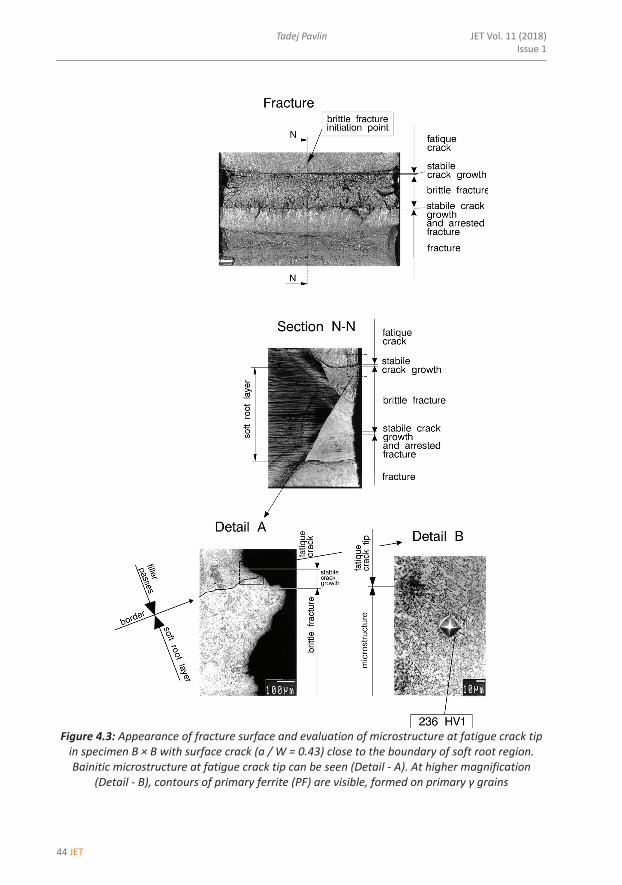
To analyse the effect of soft root layers on fracture toughness of filler passes and also of heterogeneous welds as a whole, it was necessary to locate the fatigue crack so that it gradually approaches the soft root layer (Table 3.2). From the comparison of CTOD results (Figures. 3.2 and 3.3), the effect of crack depth a/W and weld width 2H (Table 3.2) on CTOD fracture toughness is clear, being the lowest for the specimens with deep crack (a/W ̴ 0.5) in soft root layer, where the weld width 2H is the smallest. The effect of constraint on fracture toughness is also noticeable from the comparison of the curves F‐CTOD, where it is clear that the final instabilities and higher CTOD values have appeared at higher forces and for specimens with shorter cracks, where the crack tip was located approximately 2 mm above the soft root layer (Figure 4.3. ‐ cross‐section N‐N and detail A). This was not only a consequence of the remaining ligament W ‐ a and the effect of weld groove width, 2H, on the CTOD values, but also a consequence of the beneficial effect of bainitic microstructure at the fatigue crack tip, which directly reflects the fracture toughness values. Because of that, the final fracture of specimens with the crack positioned close to the soft root layer appeared after prior stable crack growth (Figure 4.3. – detail A) through the tougher bainitic microstructure (Figure 4.3. ‐ detail B) of filler passes, when the crack tip reached the soft root layer.
The soft‐root‐layer low toughness was determined by Charpy impact V testing (Table 3.1.). The main cause for low soft‐root‐layer toughness was a change of microstructure of all‐weld metal obtained by wire WELTEC B 370, which was exposed to different alloying mechanisms during welding in the root region. Specifically, the all‐weld metal microstructure of soft root weld metal was bainitic, having high toughness, but because of the above‐mentioned reasons, its microstructure was changed to harmful ferritic microstructure (Figure 4.4. ‐ detail B), causing low toughness of soft root layer.
44 JET
JET Vol. 11 (2018)Issue 1
Tadej Pavlin10 Tadej Pavlin JET Vol. 11 (2018) Issue 1
‐‐‐‐‐‐‐‐‐‐
Figure 4.3: Appearance of fracture surface and evaluation of microstructure at fatigue crack tip in specimen B × B with surface crack (a / W = 0.43) close to the boundary of soft root region. Bainitic microstructure at fatigue crack tip can be seen (Detail ‐ A). At higher magnification
(Detail ‐ B), contours of primary ferrite (PF) are visible, formed on primary γ grains

JET 45
Mechanical testing of heterogeneous energy components Mechanical testing of heterogeneous energy components 11
‐‐‐‐‐‐‐‐‐‐
Figure 4.4: Fracture and microstructure near the brittle fracture initiation point of specimen B x B with fatigue crack (a / W = 0.48) positioned in soft root region. Ferritic‐bainitic microstructure
of soft root weld metal (Detail ‐ A) is visible with distributed brittle M‐A constituents along ferrite grain boundaries (Detail ‐ B)
46 JET
JET Vol. 11 (2018)Issue 1
Tadej Pavlin12 Tadej Pavlin JET Vol. 11 (2018) Issue 1
‐‐‐‐‐‐‐‐‐‐
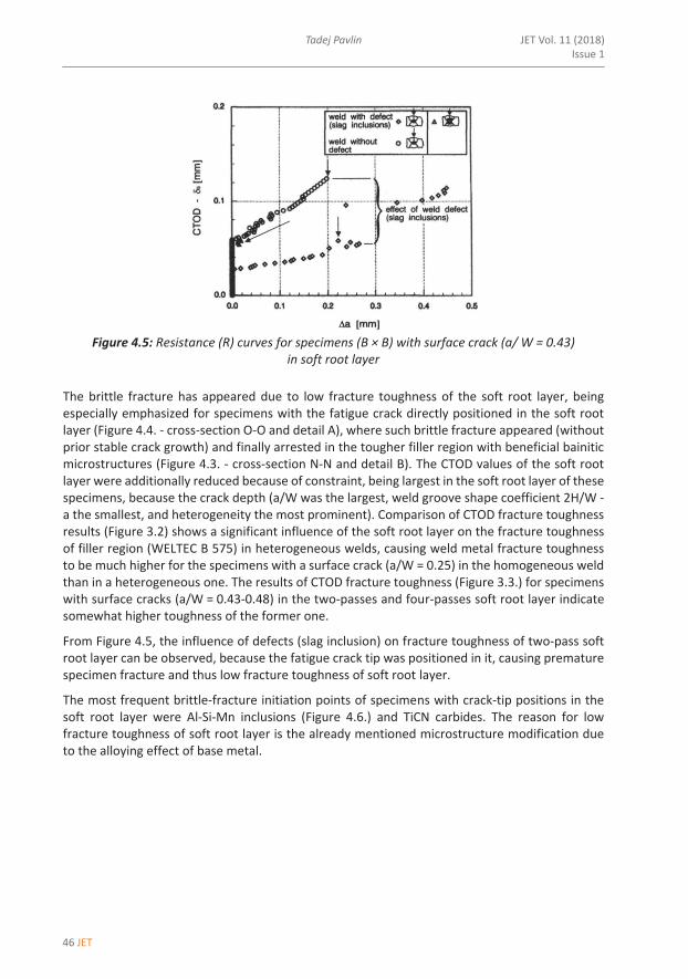
Figure 4.5: Resistance (R) curves for specimens (B × B) with surface crack (a/ W = 0.43)
in soft root layer The brittle fracture has appeared due to low fracture toughness of the soft root layer, being especially emphasized for specimens with the fatigue crack directly positioned in the soft root layer (Figure 4.4. ‐ cross‐section O‐O and detail A), where such brittle fracture appeared (without prior stable crack growth) and finally arrested in the tougher filler region with beneficial bainitic microstructures (Figure 4.3. ‐ cross‐section N‐N and detail B). The CTOD values of the soft root layer were additionally reduced because of constraint, being largest in the soft root layer of these specimens, because the crack depth (a/W was the largest, weld groove shape coefficient 2H/W ‐ a the smallest, and heterogeneity the most prominent). Comparison of CTOD fracture toughness results (Figure 3.2) shows a significant influence of the soft root layer on the fracture toughness of filler region (WELTEC B 575) in heterogeneous welds, causing weld metal fracture toughness to be much higher for the specimens with a surface crack (a/W = 0.25) in the homogeneous weld than in a heterogeneous one. The results of CTOD fracture toughness (Figure 3.3.) for specimens with surface cracks (a/W = 0.43‐0.48) in the two‐passes and four‐passes soft root layer indicate somewhat higher toughness of the former one.
From Figure 4.5, the influence of defects (slag inclusion) on fracture toughness of two‐pass soft root layer can be observed, because the fatigue crack tip was positioned in it, causing premature specimen fracture and thus low fracture toughness of soft root layer.
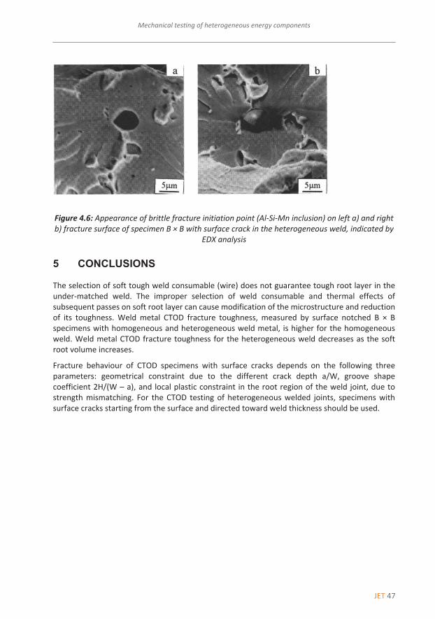
The most frequent brittle‐fracture initiation points of specimens with crack‐tip positions in the soft root layer were Al‐Si‐Mn inclusions (Figure 4.6.) and TiCN carbides. The reason for low fracture toughness of soft root layer is the already mentioned microstructure modification due to the alloying effect of base metal.
JET 47
Mechanical testing of heterogeneous energy components Mechanical testing of heterogeneous energy components 13
‐‐‐‐‐‐‐‐‐‐
Figure 4.6: Appearance of brittle fracture initiation point (Al‐Si‐Mn inclusion) on left a) and right b) fracture surface of specimen B × B with surface crack in the heterogeneous weld, indicated by
EDX analysis 5 CONCLUSIONS
The selection of soft tough weld consumable (wire) does not guarantee tough root layer in the under‐matched weld. The improper selection of weld consumable and thermal effects of subsequent passes on soft root layer can cause modification of the microstructure and reduction of its toughness. Weld metal CTOD fracture toughness, measured by surface notched B × B specimens with homogeneous and heterogeneous weld metal, is higher for the homogeneous weld. Weld metal CTOD fracture toughness for the heterogeneous weld decreases as the soft root volume increases.
Fracture behaviour of CTOD specimens with surface cracks depends on the following three parameters: geometrical constraint due to the different crack depth a/W, groove shape coefficient 2H/(W – a), and local plastic constraint in the root region of the weld joint, due to strength mismatching. For the CTOD testing of heterogeneous welded joints, specimens with surface cracks starting from the surface and directed toward weld thickness should be used.

48 JET
JET Vol. 11 (2018)Issue 1
Tadej Pavlin14 Tadej Pavlin JET Vol. 11 (2018) Issue 1
‐‐‐‐‐‐‐‐‐‐
References
[1] BS 5762, Methods for crack opening displacement (COD) testing, The British Standards Institution, London 1979
[2] ASTM E 1152‐87, Standard test method for determining J‐R curves, Annual Book of ASTM Standards, Vol. 03.01, American Society for Testing and Materials, Philadelphia, 1990
[3] ASTM E 1290‐91, Standard test method for crack‐tip opening displacement (CTOD) fracture toughness measurement, American Society for Testing and Materials, Philadelphia, 1991
[4] GKSS Forschungszentrum Geesthacht GMBH, GKSS‐Displacement Gauge Systems for Applications in Fracture Mechanic
[5] Z. Praunseis, M. Toyoda, T. Sundararajan: Fracture behaviours of fracture toughness testing specimens with metallurgical heterogeneity along crack front, Steel res., 71, Vol. 9, 2000
[6] Z. Praunseis, T. Pavlin: Mehansko preizkušanje jeklenih zvarov za procesno industrijo, študija projekta, Fakulteta za energetiko, 2016
[7] T. Sundararajan, Z. Praunseis: The effect of nitrogen‐ion implantation on the corrosion resistance of titanium in comparison with oxygen‐ and argon‐ion implantations. Mater. tehnol., Vol. 38, Iss. ½, 2004