mechanical testing of materials
DESCRIPTION
mechanical testingTRANSCRIPT

MECHANICAL TESTING OF MATERIALS
CONTENTS
Concept of stress & strain, Tensile Properties, Impact, hardness, Rockwell, Vickers, Brinell hardness testing, Fatigue,
Plastic Deformation, Slip & Twinning, Mechanism of Slip, Work hardening, Recovery, Recrystallisation & Grain growth

INTRODUCTION
• The mechanical properties of a material are used to determine its suitability for a particular application. It is convenient to break the properties, and the tests that measure them, into several types:
• Slow application of stress, as in the tensile test, allows dislocations time to move.
• Rapid stress application, as in an impact test, measures the ability of the material to absorb energy as it fails.
• The materials response to the presence of cracks and flaws that act as stress concentrators is measured by fracture toughness.
• Repeated application of stresses below the failure stress determined in a tensile test can cause fatigue failure.
• At high temperatures, materials deform continuously under an applied stress, as measured by the creep test.


TENSILE TESTS• In the tensile test the strength of the material is determined
by subjected to a simple stretching operation.• Standard dimension test samples are pulled slowly at a
uniform rate in a testing machine • The strain, the elongation of the sample is done
• The stress, the applied force divided by the original cross-
sectional area,

Engineering Stress strain diagram
of Aluminum Material

• Modulus of elasticity: The initial slope of the curve, related directly to the strength of the atomic bonds.
• YIELD STRENGTH: The point at which a consistent and measurable amount of permanent strain remains in the specimen.
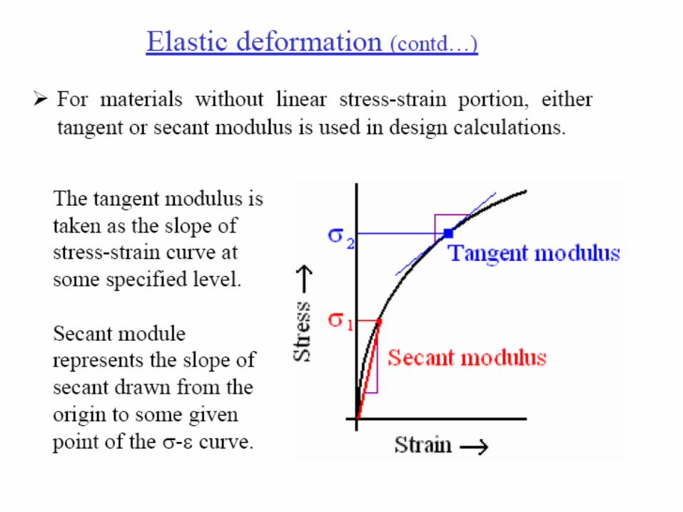

Tangent modulus: Tangent modulus: In solid mechanics, the tangent modulus is the slope of the compression stress-strain curve at any specified stress or strain. Below the proportional limit the tangent modulus is equivalent to Young's modulus. Above the proportional limit the tangent modulus varies with strain and is most accurately found from test data.
The tangent modulus is useful in describing the behavior of materials that have been stressed beyond the elastic region. When a material is plastically deformed there is no longer a linear relationship between stress and strain as there is for elastic deformations. The tangent modulus quantifies the "softening" of material that generally occurs when it begins to yield.
Although the material softens it is still generally able to sustain more load before ultimate failure. Therefore, more weight efficient structure can be designed when plastic behavior is considered. For example, a structural analyst may use the tangent modulus to quantify the buckling failure of columns and flat plates.

Modulus of Resilience The area under the linear part of the curve measuring the stored elastic energy.
TENSILE STRENGTH: The maximum stress applied to the specimen
FAILURE STRENGTH: The stress applied to the specimen at failure (usually less than the maximum tensile strength because necking reduces the cross-sectional area).

DUCTILITY: The total elongation of the specimen due to plastic deformation, neglecting the elastic stretching
TOUGHNESS
The total area under the curve which measures the energy absorbed by the specimen in the process of breaking.

Offset Yield StrengthOffset Yield Strength • Some materials do show an abrupt yield point . In plain carbon steels, the carbon atoms may diffuse to the dislocations in the material and pin them so that they cannot easily move. When the applied stress causes the dislocations to jump free of these points, they can move more easily.
• In many polymers, a similar effect is produced when bonds between molecules break and they begin to move.
NECKINGNECKING
The Engineering Stress-Strain curve of a ductile material usually drops past the tensile strength point. This is because the cross-sectional area of the material decreases because of slip along atom planes that are oriented at an angle to the applied force (of course, the slip occurs by dislocation motion). This local deformation is called a neck. Because of the decreased area, a smaller amount of force is required to continue the material's deformation. A plot of the true local stress vs. true strain, based on the changing specimen dimensions rather than the original dimensions, would continue to rise when necking occurs. However, these are rarely used because they are difficult to measure.

The Poisson ratioThe Poisson ratio is the ratio of the lateral compression to the longitudinal deformation.
Property: Temperature Change
Increase Decrease
Elastic Modulus: Decrease Increase
Tensile Strength: Decrease Increase
Yield Strength: Decrease Increase
Ductility: Increase Decrease

HARDNESS TESTS• Features:Features: quick, inexpensive and non-destructive way to estimate the
tensile strength of a specimen• Procedure:Procedure: make a small (sometimes microscopic) indentation into the
surface of a specimen, then use the force applied and the size of the indentation (depth of penetration or diameter of the indenter) to calculate a "hardness number."
• The correlation between this value and the tensile strength allows this to
be used as a quality control parameter. The Brinell Hardness Test The Brinell Hardness Test utilizes a steel sphere which is usually 10 mm in diameter. The sphere is forced into the surface of a material. Then, the diameter of the resulting impression is measured. The corresponding Brinell Hardness number is then calculated.

The Rockwell Hardness Test • The Rockwell Hardness Test utilizes two kinds of indenters. • A small steel ball is used for soft materials, and a diamond-shaped
cone, called a Brale, is used for hard materials. • To perform the test, the indenter is pushed into the surface of the
material being tested. • The test machine measures the depth of penetration and
automatically converts this data into a Rockwell Hardness number.
KNOOP TestKNOOP Test
• It is a micro hardness tests and the indentations are such small that a microscope is required to obtain the tests.
• The load is less than 2N
VICKERS TESTVICKERS TEST
• Uses Diamond pyramid indentor. It can be both micro hardness aswell as macro hardness tests

Impact Testing• It is important to examine a material's reaction to short yet intense
loads because under such conditions, the material may behave in a more brittle manner than is indicated from a simple tensile test.
• The Charpy / Izode impact test is commonly used for this purpose. • A notched bar is placed in the test machine , and then a hammer is
allowed to fall and break it.• The energy absorbed in fracturing the specimen is measured by the
height to which the hammer rises. • The hammer strikes the bar behind the notch, and the fracture starts
at the bottom of the notch and tears through the bar • The impact energy is correlated with the toughness determined in a
tensile test (area under the stress-strain curve).

• The key to toughness is a good combination of strength and ductility. A material with high strength and high ductility will have more toughness than a material with low strength and high ductility
Impact and ToughnessImpact and Toughness• There is a direct relationship between the energy absorbed in impact and
the toughness measured as the area under the stress-strain curve • Materials with a high toughness value absorb more energy in fracture
which may provide a margin of safety in real structures in the event of failure.
• A sledgehammer is used to hammer a typical steel fender , it deforms but absorbs the energy.
• Hitting a fiberglass fender produces fracture with little deformation, absorbing less energy.
• Some newer cars use plastic body parts (in this example, a polyurethane foam) which have a large range of elastic deformation so that fracture does not occur at all.

FATIGUE TESTING• Material that is subjected to a repeated application of a stress may fail
even if the stress it is subjected to is lower than the yield strength.
• Such failure is referred to as Fatigue and results from the accumulation of very small amounts of deformation in the nominally elastic range.
• The typical fatigue test results plot the failure stress versus the number of cycles (on a logarithmic scale).
• A single application of stress is the same as the tensile strength, but the stress needed to cause failure typically drops with the number of cycles.
• For steels and many other BCC metals, an endurance limit (about half the tensile strength) is reached below which there is a 50% chance that failure will not occur with any number of cycles.

• Most FCC metals do not exhibit an endurance limit.
• Fatigue is an important cause of failure in many cases because it can form cracks that grow until they are large enough to cause a fracture toughness failure.
• Fatigue can result from cyclical application of tension and compression (bending, as in springs or the flexing of aircraft or other structures), tension only (springs, elevator cables), or compression only (bearing contacts, railroad rails).


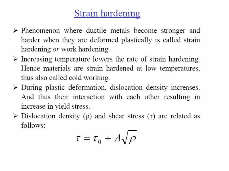
• Resistance to continuing plastic flow as a metal is worked is termed 'work hardening.
Frank reed sources
STRAIN HARDENINGSTRAIN HARDENING


RECOVERY
RECRYSTALLIZATION
GRAIN GROWTH