mechanical anchors for seismic bracing
TRANSCRIPT

MECHANICAL ANCHORS FOR SEISMIC BRACINGNFPA 13 seismic bracing anchor load tables

2 April 2020
HILTI MECHANICAL ANCHORS AND CAST-IN ANCHORS FOR SEISMIC BRACING IN ACCORDANCE WITH NFPA 13Hilti post-installed mechanical anchors and single point cast-in-place anchors are common, cost effective methods for attaching both structural and non-structural elements to concrete base materials. Non-structural elements, such as fire sprinkler pipes; electrical conduit and cable trays; heating, ventilation and air conditioning (HVAC) equipment and ductwork are especially suited for Hilti anchoring systems.
For fire sprinkler pipe applications, Hilti anchors have been effectively used for many years to support the gravity loaded hangers as well as the sway bracing for resisting the lateral and vertical motion resulting from seismic loads.
Seismic hinge with Hilti anchor
Seismic hinge with Hilti anchor
Figure 1 — Typical sprinkler pipe hanger with seismic sway
While Hilti anchors can be designed and installed to support gravity loads of the pipe through the attachment of the hanger to the concrete, this document will focus on the design of the anchorage to attach the sway brace assembly to the concrete structure. Contact Hilti for more information related to Hilti anchors to support the vertical pipe hanger.
In a seismic event the earthquake forces are resisted by the transverse and longitudinal sway bracing and the sway braces will transfer the loads through a fastener that is attached to the concrete. In general, the capacity of the fastener in concrete is dictated by a design per ACI 318-14 Chapter 17, and the design of the sway brace components is dictated by NFPA 13-16 Section 9.3.5.
Note: For simplicity, this document will reference the 2016 NFPA-13 document sections.
This document will not cover the design of the components of the pipe support hangers or sway bracing. Rather, this document will provide the maximum horizontal load that can be applied to the sway brace, Fpw, based on the Hilti fastener type and embedment depth, fastener load capacity, the concrete strength and configuration, the sway brace to fastener connector (seismic hinge) geometry, and the brace angle. See Figure 2 on the following page. Fpw does not consider the adequacy of the seismic hinge or other components of the sway bracing or vertical hanger. The design engineer of record must ensure all of these components are suitable for the application and design loads.
This document is a supplement to the Hilti North American Product Technical Guide, Volume 2, Anchor Fastening Technical Guide, Edition 19 (PTG Ed. 19). Please refer to the publication in its entirety, which is available at www.hilti.com or www.hilti.ca, for complete details including data development, product specifications, general suitability, installation, corrosion and spacing and edge distance guidelines, for the Hilti anchoring systems noted within.
Front view Side view

Anchorage for seismic bracing technical supplement
3April 2020
Figure 2 — Sway brace load, Fpw, from typical sway brace configuration (Source: NFPA 13 2016 Edition Figure 9.3.5.12.1)
Horizontal earthquake load design per NFPA-13The maximum horizontal earthquake load, Fpw that will not exceed the allowable capacity of the anchor, can be derived from NFPA 13-16 Eq. A.9.3.5.12.2a:
T+
V≤ 1.2
Tallow Vallow
where:T = applied service tension load, including the effect of prying = Fpw x Pr for all Angle CategoriesFpw = horizontal earthquake loadPr = prying factor based on fitting geometry and brace angle from vertical as determined from NFPA 13-16 A.9.3.5.12.2Tallow = allowable service tension loadV = applied service shear load =
Angle Category A, B, and C: V = Fpw
Angle Category D, E, and F: V =Fpw
tanθ
Angle Category G, H, and I: V =Fpw
sinθ
θ = brace angle (see Figure 2)
Vallow = allowable service shear loadT/Tallow shall not be greater than 1.0V/Vallow shall not be greater than 1.0
Substituting for T and V for the various angle categories:
Angle Category A, B, and C:
Fpw ∙ Pr +Fpw ≤ 1.2
Tallow Vallow
where:Fpw ∙ Pr / Tallow ≤ 1.0Fpw / Vallow ≤ 1.0
Angle Category D, E, and F:
Fpw ∙ Pr +Fpw / tanθ
≤ 1.2Tallow Vallow
where:Fpw ∙ Pr / Tallow ≤ 1.0(Fpw / tanθ) / Vallow ≤ 1.0
Angle Category G, H, and I:
Fpw ∙ Pr +Fpw / sinθ
≤ 1.2Tallow Vallow
where:Fpw ∙ Pr / Tallow ≤ 1.0(Fpw / sinθ) / Vallow ≤ 1.0

4 April 2020
Design Tables for Pre-calculated Horizontal Earthquake LoadThe design tables starting on page 7 determine the maximum horizontal load, Fpw, that will satisfy NFPA 13-16 Eq. A.9.3.5.12.2a, for various Hilti post-installed and cast-in anchors used in conjunction with various seismic brace swivel attachments to attach the sway brace to concrete.
Notes:• Tallow and Vallow used as the calculation basis for Fpw in the tables are determined from a strength design calculation according to
ACI 318-14 Ch. 17 and converted to allowable values per NFPA 13-16 A.9.3.5.12.8.3(D).• Anchor calculation assumes cracked concrete condition and seismic design category C through F.• Minimum edge distance noted in tables assumes a single anchor with one nearby edge with the shear load perpendicular toward
the edge. For an anchor in a corner, the distance to the edge parallel to the direction of the shear must be at least 1.5 times the minimum edge distance noted in the table.
• Minimum spacing distance noted in tables assumes two anchors in the middle of the concrete with no edge distance reductions.• Seismic brace swivel attachment prying factors noted in the tables are from data published according to the following documents
• Hilti MQS-SP-L-1/2” and MQS-SP-T-1/2” seismic hinge prying factors taken from Hilti Statement on the Prying Factors in regard to Hilti Seismic hinge (all sizes) technical document, dated November 18, 2019.
• Tolco™ Figure 909, 910, and 980 swivel brace attachment prying factors taken from Seismic Bracing Anchor Load Charts B-Line series technical publication no. BR309004EN, dated October 2019
• Afcon™ AF075, AF076, AF077, and AF771 swivel brace attachment prying factors taken from Anvil International Pipe Hangers and Supports technical publication no. 165, with a revision date of January 29, 2018.
• The above noted documents are subject to change and only valid for the dates listed in the referenced documents.• TOLCO™ trademark is owned by Eaton Corporation plc.• AFCON™ trademark is owned by Anvil International LLC.
• Prying factors are provided that give the highest value for the given angle category. The corresponding value of Pr and Fpw will be conservative for the other angles within the angle category.
• For angle categories D to I, the angle, θ, is selected that leads to the highest value for the applied shear load, V. The corresponding value of Fpw will be conservative for the other angles within the angle category. θ = 30° for Angle D and G, θ = 45° for Angle E and H, and θ = 60° for Angle F and I.
• Fpw does not consider the adequacy of the seismic hinge or other components of the sway bracing or vertical hanger. The design engineer of record must ensure all components are suitable for the application and design loads.
• Prying factors noted for the attachment to concrete over metal deck assume the seismic swivel brace has its full bearing area in contact with the metal deck.
• Values in tables are applicable for noted concrete compressive strength and for concrete with higher compressive strengths.• For applications outside of the above noted parameters, contact Hilti for assistance.
Anchorage for seismic bracing technical supplement
5April 2020
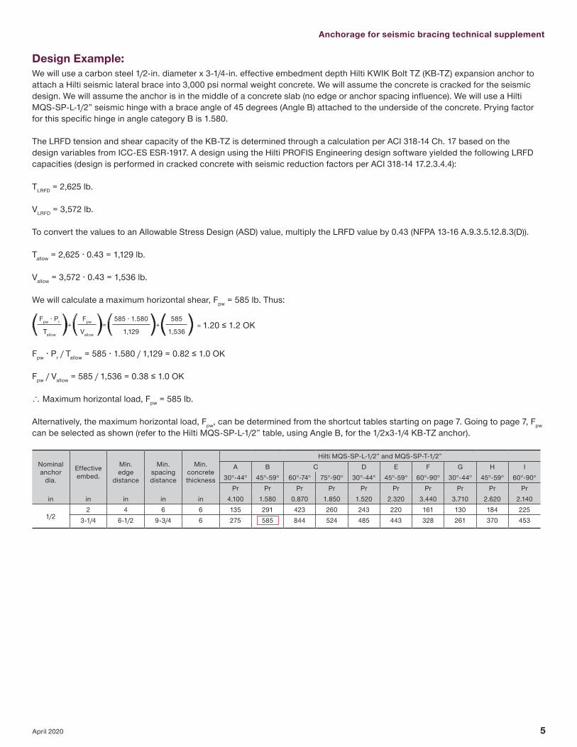
Design Example:We will use a carbon steel 1/2-in. diameter x 3-1/4-in. effective embedment depth Hilti KWIK Bolt TZ (KB-TZ) expansion anchor to attach a Hilti seismic lateral brace into 3,000 psi normal weight concrete. We will assume the concrete is cracked for the seismic design. We will assume the anchor is in the middle of a concrete slab (no edge or anchor spacing influence). We will use a Hilti MQS-SP-L-1/2” seismic hinge with a brace angle of 45 degrees (Angle B) attached to the underside of the concrete. Prying factor for this specific hinge in angle category B is 1.580.
The LRFD tension and shear capacity of the KB-TZ is determined through a calculation per ACI 318-14 Ch. 17 based on the design variables from ICC-ES ESR-1917. A design using the Hilti PROFIS Engineering design software yielded the following LRFD capacities (design is performed in cracked concrete with seismic reduction factors per ACI 318-14 17.2.3.4.4):
TLRFD = 2,625 lb.
VLRFD = 3,572 lb.
To convert the values to an Allowable Stress Design (ASD) value, multiply the LRFD value by 0.43 (NFPA 13-16 A.9.3.5.12.8.3(D)).
Tallow = 2,625 ∙ 0.43 = 1,129 lb.
Vallow = 3,572 ∙ 0.43 = 1,536 lb.
We will calculate a maximum horizontal shear, Fpw = 585 lb. Thus:
Fpw ∙ Pr +Fpw =
585 ∙ 1.580+
585= 1.20 ≤ 1.2 OK
Tallow Vallow 1,129 1,536
Fpw ∙ Pr / Tallow = 585 ∙ 1.580 / 1,129 = 0.82 ≤ 1.0 OK
Fpw / Vallow = 585 / 1,536 = 0.38 ≤ 1.0 OK
∴ Maximum horizontal load, Fpw = 585 lb.
Alternatively, the maximum horizontal load, Fpw, can be determined from the shortcut tables starting on page 7. Going to page 7, Fpw can be selected as shown (refer to the Hilti MQS-SP-L-1/2” table, using Angle B, for the 1/2x3-1/4 KB-TZ anchor).
Nominalanchor
dia.
Effectiveembed.
Min.edge
distance
Min.spacingdistance
Min.concretethickness
Hilti MQS-SP-L-1/2” and MQS-SP-T-1/2”A B C D E F G H I
30°-44° 45°-59° 60°-74° 75°-90° 30°-44° 45°-59° 60°-90° 30°-44° 45°-59° 60°-90°Pr Pr Pr Pr Pr Pr Pr Pr Pr Pr
in in in in in 4.100 1.580 0.870 1.850 1.520 2.320 3.440 3.710 2.620 2.140
1/22 4 6 6 135 291 423 260 243 220 161 130 184 225
3-1/4 6-1/2 9-3/4 6 275 585 844 524 485 443 328 261 370 453

6 April 2020
CONTENTS
CARBON STEEL KWIK BOLT TZ 7The Hilti KB-TZ is the most versatile anchor of the group and is most often used for pipe supports in seismic areas. The design capacity is the best of its class while remaining a cost effective solution that is easy to install. The anchor is available in 3/8-in.to 3/4-in. diameters and is supported by ICC-ES ESR-1917 and has FM and UL listings for fire-sprinkler applications.
3,000 psi flat slab concrete 7
4,000 psi flat slab concrete 8
5,000 psi flat slab concrete 9
6,000 psi flat slab concrete 10
3,000 and 4,000 psi lightweight concrete over metal deck 113-in. deck profiles (i.e. W2, W3) 111-1/2-in. deck profiles (i.e. B) 12
KCS-WF 13The KCS-WF cast-in anchor has a single internal thread and is an easy installation solution for flat concrete slabs that requires no drilling after the concrete is cast. The anchor is available in 1/4-in. to 3/4-in. inner thread diameters (3/8-in to 3/4-in. diameters are applicable for seismic bracing) and is supported by ICC-ES ESR-4006 and has FM and UL listings for fire-sprinkler applications.
3,000 psi flat slab concrete 13
4,000 psi flat slab concrete 14
5,000 psi flat slab concrete 15
6,000 psi flat slab concrete 16
KCM-WF/-PD 17The KCM-WF/-PD cast-in anchor has multiple internal threads for ultimate flexibility for many pipe sizes and is intended for flat concrete slabs. The anchor is available in 1/4-in. to 3/4-in. inner thread diameters (3/8-in to 3/4-in. diameters are applicable for seismic bracing) and is supported by ICC-ES ESR-4145 and has FM and UL listings for fire-sprinkler applications.
3,000 psi flat slab concrete 17
4,000 psi flat slab concrete 18
5,000 psi flat slab concrete 19
6,000 psi flat slab concrete 20
KCM-MD 21The KCM-MD cast-in anchor has been optimized for installation in concrete over metal deck applications. With a short plate option for direct installation on the deck or a long plate option to span the lower flutes, the KCM-MD has tremendous flexibility for the fire sprinkler pipe installer. Short plate anchors are shown in this supplement. The KCM-MD is supported by ICC-ES ESR-4145 and has FM and UL listings for fire-sprinkler applications.
3,000 and 4,000 psi lightweight concrete over metal deck 213-in. deck profiles (i.e. W2, W3) 211-1/2-in. deck profiles (i.e. B) 22
HILTI MQS-SP-L-1/2” AND MQS-SP-T-1/2” The Hilti Seismic Hinge MQS-SP is a versatile and quick connect solution for seismic bracing attachments. FM rated for seismic solutions for the lateral or transversal brace assembly. Contact Hilti for more information on the seismic hinge and other Hilti pipe support solutions.
For comprehensive information on the above noted anchors reference the Hilti North American Product Technical Guide, Volume 2: Anchor Fastening Technical Guide, Edition 19, or the above noted ICC Evaluation Service reports.

Anchorage for seismic bracing technical supplement
7April 2020
Maximum allowable pipe horizontal load, Fpw (lb) Carbon steel Hilti KWIK Bolt TZ in 3,000 psi normal weight cracked concrete
Nominalanchor
dia.
Effectiveembed.
Min.edge
distance
Min.spacingdistance
Min.concretethickness
Hilti MQS-SP-L-1/2” and MQS-SP-T-1/2”A B C D E F G H I
30°-44° 45°-59° 60°-74° 75°-90° 30°-44° 45°-59° 60°-90° 30°-44° 45°-59° 60°-90°Pr Pr Pr Pr Pr Pr Pr Pr Pr Pr
in in in in in 4.100 1.580 0.870 1.850 1.520 2.320 3.440 3.710 2.620 2.140
1/2 2 4 6 6 135 291 423 260 243 220 161 130 184 2253-1/4 6-1/2 9-3/4 6 275 585 844 524 485 443 328 261 370 453
Nominalanchor
dia.
Effectiveembed.
Min.edge
distance
Min.spacingdistance
Min.concretethickness
Tolco™ Figure 909 seismic braceA B C D E F G H I
30°-44° 45°-59° 60°-74° 75°-90° 30°-44° 45°-59° 60°-90° 30°-44° 45°-59° 60°-90°Pr Pr Pr Pr Pr Pr Pr Pr Pr Pr
in in in in in 2.626 1.002 0.870 1.230 1.513 1.487 2.226 2.460 1.740 1.420
3/81-1/2 8 8 6 113 229 250 200 144 175 136 100 142 173
2 3-1/2 6 6 181 342 369 304 212 270 231 152 215 2632-3/4 3-1/2 8-1/4 6 230 404 431 365 248 330 301 183 258 316
1/2 2 4 6 6 199 390 423 344 244 303 248 172 243 2983-1/4 6-1/2 9-3/4 6 403 780 844 689 486 610 507 345 487 597
5/8 3-1/8 8-1/2 9-3/8 6 411 857 939 745 541 649 484 372 526 6454 8-1/4 12 6 557 1079 1167 953 672 843 701 477 674 826
3/43-1/4 12-1/4 9-3/4 6 436 1016 1126 870 648 748 514 435 615 7533-3/4 12 11-1/4 6 540 1186 1306 1023 752 886 637 512 724 8864-3/4 10 14-1/4 8 748 1499 1632 1314 940 1153 908 657 929 1138
Nominalanchor
dia.
Effectiveembed.
Min.edge
distance
Min.spacingdistance
Min.concretethickness
Tolco™ Figure 910/980 seismic braceA B C D E F G H I
30°-44° 45°-59° 60°-74° 75°-90° 30°-44° 45°-59° 60°-90° 30°-44° 45°-59° 60°-90°Pr Pr Pr Pr Pr Pr Pr Pr Pr Pr
in in in in in 3.275 1.156 0.910 1.739 1.461 1.850 2.895 3.478 2.459 2.008
3/81-1/2 8 8 6 93 209 243 156 147 149 105 78 111 135
2 3-1/2 6 6 152 315 360 244 216 234 180 122 172 2112-3/4 3-1/2 8-1/4 6 197 377 422 301 252 290 244 151 213 261
1/2 2 4 6 6 167 358 412 272 248 260 191 136 192 2363-1/4 6-1/2 9-3/4 6 338 716 823 548 495 524 390 274 387 474
5/8 3-1/8 8-1/2 9-3/8 6 329 778 913 576 553 549 373 288 407 4994 8-1/4 12 6 467 991 1139 758 685 725 540 379 536 656
3/43-1/4 12-1/4 9-3/4 6 349 912 1091 658 665 618 395 329 465 5703-3/4 12 11-1/4 6 433 1071 1268 784 770 745 490 392 554 6794-3/4 10 14-1/4 8 617 1369 1589 1030 959 983 698 515 728 892
Nominalanchor
dia.
Effectiveembed.
Min.edge
distance
Min.spacingdistance
Min.concretethickness
Afcon™ AF075/AF076/AF077 seismic braceA B C D E F G H I
30°-44° 45°-59° 60°-90° 30°-44° 45°-59° 60°-90° 30°-44° 45°-59° 60°-90°Pr Pr Pr Pr Pr Pr Pr Pr Pr
in in in in in 3.724 2.150 1.375 2.150 2.150 2.250 2.750 1.945 1.588
1/2 2 4 6 6 148 233 320 197 233 245 167 251 3333-1/4 6-1/2 9-3/4 6 303 470 642 396 470 502 337 505 673
Nominalanchor
dia.
Effectiveembed.
Min.edge
distance
Min.spacingdistance
Min.concretethickness
Afcon™ AF771 seismic braceA B C D E F G H I
30°-44° 45°-59° 60°-90° 30°-44° 45°-59° 60°-90° 30°-44° 45°-59° 60°-90°Pr Pr Pr Pr Pr Pr Pr Pr Pr
in in in in in 4.170 2.000 0.964 1.966 2.385 2.964 1.929 1.364 1.113
1/2 2 4 6 6 132 246 399 209 215 186 211 322 4373-1/4 6-1/2 9-3/4 6 271 495 797 418 434 381 423 645 881
5/8 3-1/8 8-1/2 9-3/8 6 259 516 879 455 447 364 461 691 9204 8-1/4 12 6 374 685 1103 578 601 527 585 893 1219
3/43-1/4 12-1/4 9-3/4 6 274 572 1046 534 480 386 542 802 10283-3/4 12 11-1/4 6 381 659 941 627 594 478 635 947 12484-3/4 10 14-1/4 8 543 877 1218 800 808 682 810 1225 1651
3,000 psiNWC
Tallow Tallow
Vallow
Min. spacing1.5 x Min.
edge distance
Min
. con
c.
thic
knes
s
Min
. con
c.
thic
knes
s
Min. edge distance

8 April 2020
Maximum allowable pipe horizontal load, Fpw (lb)Carbon steel Hilti KWIK Bolt TZ in 4,000 psi normal weight cracked concrete
Nominalanchor
dia.
Effectiveembed.
Min.edge
distance
Min.spacingdistance
Min.concretethickness
Hilti MQS-SP-L-1/2" and MQS-SP-T-1/2"A B C D E F G H I
30°-44° 45°-59° 60°-74° 75°-90° 30°-44° 45°-59° 60°-90° 30°-44° 45°-59° 60°-90°Pr Pr Pr Pr Pr Pr Pr Pr Pr Pr
in in in in in 4.100 1.580 0.870 1.850 1.520 2.320 3.440 3.710 2.620 2.140
1/2 2 4 6 6 156 336 488 300 281 254 185 150 212 2603-1/4 6-1/2 9-3/4 6 316 644 910 580 523 494 379 289 409 501
Nominalanchor
dia.
Effectiveembed.
Min.edge
distance
Min.spacingdistance
Min.concretethickness
Tolco™ Figure 909 seismic braceA B C D E F G H I
30°-44° 45°-59° 60°-74° 75°-90° 30°-44° 45°-59° 60°-90° 30°-44° 45°-59° 60°-90°Pr Pr Pr Pr Pr Pr Pr Pr Pr Pr
in in in in in 2.626 1.002 0.870 1.230 1.513 1.487 2.226 2.460 1.740 1.420
3/81-1/2 8 8 6 131 264 288 231 166 203 157 116 163 200
2 3-1/2 6 6 202 369 396 331 228 296 260 165 234 2862-3/4 3-1/2 8-1/4 6 254 431 457 393 263 357 336 196 278 340
1/2 2 4 6 6 230 451 488 397 281 350 286 199 281 3443-1/4 6-1/2 9-3/4 6 450 845 910 752 524 670 576 376 532 652
5/8 3-1/8 8-1/2 9-3/8 6 465 941 1026 823 591 720 559 411 582 7134 8-1/4 12 6 623 1169 1259 1041 725 926 797 520 736 901
3/43-1/4 12-1/4 9-3/4 6 503 1128 1246 971 717 839 593 485 686 8413-3/4 12 11-1/4 6 623 1309 1435 1136 826 989 735 568 803 9844-3/4 10 14-1/4 8 839 1635 1771 1443 1020 1274 1048 721 1020 1250
Nominalanchor
dia.
Effectiveembed.
Min.edge
distance
Min.spacingdistance
Min.concretethickness
Tolco™ Figure 910/980 seismic braceA B C D E F G H I
30°-44° 45°-59° 60°-74° 75°-90° 30°-44° 45°-59° 60°-90° 30°-44° 45°-59° 60°-90°Pr Pr Pr Pr Pr Pr Pr Pr Pr Pr
in in in in in 3.275 1.156 0.910 1.739 1.461 1.850 2.895 3.478 2.459 2.008
3/81-1/2 8 8 6 107 241 280 181 169 172 121 90 128 156
2 3-1/2 6 6 171 342 387 268 232 258 208 134 190 2322-3/4 3-1/2 8-1/4 6 218 404 449 327 267 316 274 164 232 284
1/2 2 4 6 6 193 413 476 314 287 300 220 157 222 2723-1/4 6-1/2 9-3/4 6 379 780 889 604 534 580 450 302 427 523
5/8 3-1/8 8-1/2 9-3/8 6 380 858 999 643 603 613 430 321 454 5574 8-1/4 12 6 525 1079 1230 836 738 802 623 418 591 724
3/43-1/4 12-1/4 9-3/4 6 403 1017 1208 740 734 704 456 370 523 6413-3/4 12 11-1/4 6 500 1187 1394 878 845 836 565 439 621 7604-3/4 10 14-1/4 8 702 1500 1727 1143 1040 1093 806 571 808 990
Nominalanchor
dia.
Effectiveembed.
Min.edge
distance
Min.spacingdistance
Min.concretethickness
Afcon™ AF075/AF076/AF077 seismic braceA B C D E F G H I
30°-44° 45°-59° 60°-90° 30°-44° 45°-59° 60°-90° 30°-44° 45°-59° 60°-90°Pr Pr Pr Pr Pr Pr Pr Pr Pr
in in in in in 3.724 2.150 1.375 2.150 2.150 2.250 2.750 1.945 1.588
1/2 2 4 6 6 171 269 369 228 269 283 193 290 3853-1/4 6-1/2 9-3/4 6 342 521 703 432 521 571 371 560 753
Nominalanchor
dia.
Effectiveembed.
Min.edge
distance
Min.spacingdistance
Min.concretethickness
Afcon™ AF771 seismic braceA B C D E F G H I
30°-44° 45°-59° 60°-90° 30°-44° 45°-59° 60°-90° 30°-44° 45°-59° 60°-90°Pr Pr Pr Pr Pr Pr Pr Pr Pr
in in in in in 4.170 2.000 0.964 1.966 2.385 2.964 1.929 1.364 1.113
1/2 2 4 6 6 153 284 461 241 248 215 244 371 5053-1/4 6-1/2 9-3/4 6 312 549 863 455 484 440 460 707 976
5/8 3-1/8 8-1/2 9-3/8 6 299 578 964 501 503 420 508 766 10304 8-1/4 12 6 431 759 1194 630 669 608 637 978 1350
3/43-1/4 12-1/4 9-3/4 6 317 660 1160 595 554 446 603 897 11783-3/4 12 11-1/4 6 439 741 1048 694 681 552 703 1054 14024-3/4 10 14-1/4 8 627 979 1342 876 904 787 886 1349 1838
4,000 psiNWC
Tallow Tallow
Vallow
Min. spacing1.5 x Min.
edge distance
Min
. con
c.
thic
knes
s
Min
. con
c.
thic
knes
s
Min. edge distance

Anchorage for seismic bracing technical supplement
9April 2020
Maximum allowable pipe horizontal load, Fpw (lb)Carbon steel Hilti KWIK Bolt TZ in 5,000 psi normal weight cracked concrete
Nominal anchor dia.
Effective embed.
Min. edge distance
Min. spacing distance
Min. concrete thickness
Hilti MQS-SP-L-1/2" and MQS-SP-T-1/2"A B C D E F G H I
30°-44° 45°-59° 60°-74° 75°-90° 30°-44° 45°-59° 60°-90° 30°-44° 45°-59° 60°-90°Pr Pr Pr Pr Pr Pr Pr Pr Pr Pr
in in in in in 4.100 1.580 0.870 1.850 1.520 2.320 3.440 3.710 2.620 2.140
1/2 2 4 6 6 174 376 546 336 314 283 207 168 237 2903-1/4 6-1/2 9-3/4 6 346 692 961 625 553 535 424 312 441 540
Nominal anchor dia.
Effective embed.
Min. edge distance
Min. spacing distance
Min. concrete thickness
Tolco™ Figure 909 seismic braceA B C D E F G H I
30°-44° 45°-59° 60°-74° 75°-90° 30°-44° 45°-59° 60°-90° 30°-44° 45°-59° 60°-90°Pr Pr Pr Pr Pr Pr Pr Pr Pr Pr
in in in in in 2.626 1.002 0.870 1.230 1.513 1.487 2.226 2.460 1.740 1.420
3/81-1/2 8 8 6 144 286 311 251 179 221 176 125 177 217
2 3-1/2 6 6 219 390 417 351 240 316 284 176 248 3042-3/4 3-1/2 8-1/4 6 273 452 477 414 275 378 364 207 292 358
1/2 2 4 6 6 257 503 546 444 314 392 320 222 314 3843-1/4 6-1/2 9-3/4 6 489 896 961 803 554 718 630 401 567 695
5/8 3-1/8 8-1/2 9-3/8 6 509 1008 1095 886 631 780 625 443 626 7674 8-1/4 12 6 677 1240 1330 1110 766 993 872 555 785 962
3/43-1/4 12-1/4 9-3/4 6 562 1220 1342 1055 773 915 663 527 746 9133-3/4 12 11-1/4 6 690 1408 1538 1229 886 1074 822 614 869 10644-3/4 10 14-1/4 8 915 1742 1881 1546 1083 1372 1166 773 1093 1339
Nominal anchor dia.
Effective embed.
Min. edge distance
Min. spacing distance
Min. concrete thickness
Tolco™ Figure 910/980 seismic braceA B C D E F G H I
30°-44° 45°-59° 60°-74° 75°-90° 30°-44° 45°-59° 60°-90° 30°-44° 45°-59° 60°-90°Pr Pr Pr Pr Pr Pr Pr Pr Pr Pr
in in in in in 3.275 1.156 0.910 1.739 1.461 1.850 2.895 3.478 2.459 2.008
3/81-1/2 8 8 6 120 261 303 197 183 189 135 99 140 171
2 3-1/2 6 6 186 363 408 288 244 277 230 144 203 2492-3/4 3-1/2 8-1/4 6 236 425 469 348 278 337 299 174 246 302
1/2 2 4 6 6 215 462 532 351 321 336 246 176 248 3043-1/4 6-1/2 9-3/4 6 414 831 941 651 563 625 503 325 460 563
5/8 3-1/8 8-1/2 9-3/8 6 425 922 1067 698 643 667 481 349 493 6044 8-1/4 12 6 573 1149 1301 900 779 864 696 450 636 779
3/43-1/4 12-1/4 9-3/4 6 451 1103 1303 809 791 770 510 405 572 7013-3/4 12 11-1/4 6 559 1282 1496 956 905 912 632 478 676 8284-3/4 10 14-1/4 8 769 1605 1836 1236 1103 1184 901 618 874 1070
Nominal anchor dia.
Effective embed.
Min. edge distance
Min. spacing distance
Min. concrete thickness
Afcon™ AF075/AF076/AF077 seismic braceA B C D E F G H I
30°-44° 45°-59° 60°-90° 30°-44° 45°-59° 60°-90° 30°-44° 45°-59° 60°-90°Pr Pr Pr Pr Pr Pr Pr Pr Pr
in in in in in 3.724 2.150 1.375 2.150 2.150 2.250 2.750 1.945 1.588
1/2 2 4 6 6 191 300 413 255 300 317 216 324 4303-1/4 6-1/2 9-3/4 6 374 564 753 461 564 625 398 604 819
Nominal anchor dia.
Effective embed.
Min. edge distance
Min. spacing distance
Min. concrete thickness
Afcon™ AF771 seismic braceA B C D E F G H I
30°-44° 45°-59° 60°-90° 30°-44° 45°-59° 60°-90° 30°-44° 45°-59° 60°-90°Pr Pr Pr Pr Pr Pr Pr Pr Pr
in in in in in 4.170 2.000 0.964 1.966 2.385 2.964 1.929 1.364 1.113
1/2 2 4 6 6 171 317 515 270 277 240 273 415 5643-1/4 6-1/2 9-3/4 6 342 593 914 485 525 492 490 756 1053
5/8 3-1/8 8-1/2 9-3/8 6 334 629 1032 539 549 470 545 827 11204 8-1/4 12 6 473 820 1265 670 726 680 677 1046 1456
3/43-1/4 12-1/4 9-3/4 6 354 723 1253 645 619 498 654 977 12913-3/4 12 11-1/4 6 491 811 1136 749 746 617 759 1143 15314-3/4 10 14-1/4 8 693 1063 1443 937 985 880 947 1450 1992
5,000 psiNWC
Tallow Tallow
Vallow
Min. spacing1.5 x Min.
edge distance
Min
. con
c.
thic
knes
s
Min
. con
c.
thic
knes
s
Min. edge distance

10 April 2020
Maximum allowable pipe horizontal load, Fpw (lb) Carbon steel Hilti KWIK Bolt TZ in 6,000 psi normal weight cracked concrete
Nominal anchor dia.
Effective embed.
Min. edge distance
Min. spacing distance
Min. concrete thickness
Hilti MQS-SP-L-1/2" and MQS-SP-T-1/2"A B C D E F G H I
30°-44° 45°-59° 60°-74° 75°-90° 30°-44° 45°-59° 60°-90° 30°-44° 45°-59° 60°-90°Pr Pr Pr Pr Pr Pr Pr Pr Pr Pr
in in in in in 4.100 1.580 0.870 1.850 1.520 2.320 3.440 3.710 2.620 2.140
1/2 2 4 6 6 190 412 598 368 344 311 227 184 260 3183-1/4 6-1/2 9-3/4 6 373 731 1003 663 577 570 464 331 468 573
Nominal anchor dia.
Effective embed.
Min. edge distance
Min. spacing distance
Min. concrete thickness
Tolco™ Figure 909 seismic braceA B C D E F G H I
30°-44° 45°-59° 60°-74° 75°-90° 30°-44° 45°-59° 60°-90° 30°-44° 45°-59° 60°-90°Pr Pr Pr Pr Pr Pr Pr Pr Pr Pr
in in in in in 2.626 1.002 0.870 1.230 1.513 1.487 2.226 2.460 1.740 1.420
3/81-1/2 8 8 6 155 302 327 266 188 235 193 133 188 231
2 3-1/2 6 6 233 407 434 369 250 333 305 184 261 3192-3/4 3-1/2 8-1/4 6 289 468 493 431 284 395 389 215 304 373
1/2 2 4 6 6 282 552 598 486 345 429 351 243 344 4213-1/4 6-1/2 9-3/4 6 523 938 1003 844 578 758 678 422 597 731
5/8 3-1/8 8-1/2 9-3/8 6 547 1064 1152 939 664 830 685 470 664 8144 8-1/4 12 6 723 1298 1388 1168 800 1049 938 584 826 1011
3/43-1/4 12-1/4 9-3/4 6 616 1298 1424 1127 820 980 727 563 796 9763-3/4 12 11-1/4 6 743 1492 1625 1307 936 1147 901 653 924 11324-3/4 10 14-1/4 8 981 1831 1970 1633 1135 1455 1257 816 1154 1414
Nominal anchor dia.
Effective embed.
Min. edge distance
Min. spacing distance
Min. concrete thickness
Tolco™ Figure 910/980 seismic braceA B C D E F G H I
30°-44° 45°-59° 60°-74° 75°-90° 30°-44° 45°-59° 60°-90° 30°-44° 45°-59° 60°-90°Pr Pr Pr Pr Pr Pr Pr Pr Pr Pr
in in in in in 3.275 1.156 0.910 1.739 1.461 1.850 2.895 3.478 2.459 2.008
3/81-1/2 8 8 6 129 277 319 211 192 202 148 105 149 183
2 3-1/2 6 6 199 380 425 304 254 293 248 152 215 2632-3/4 3-1/2 8-1/4 6 251 442 485 365 288 354 321 183 258 317
1/2 2 4 6 6 236 506 583 385 351 368 270 192 272 3333-1/4 6-1/2 9-3/4 6 444 873 983 689 587 663 548 345 488 597
5/8 3-1/8 8-1/2 9-3/8 6 458 976 1124 745 677 713 527 372 527 6454 8-1/4 12 6 614 1207 1359 954 812 917 758 477 674 826
3/43-1/4 12-1/4 9-3/4 6 494 1177 1384 870 839 828 559 435 615 7533-3/4 12 11-1/4 6 612 1362 1582 1024 955 978 692 512 724 8874-3/4 10 14-1/4 8 827 1692 1926 1314 1155 1261 987 657 929 1138
Nominal anchor dia.
Effective embed.
Min. edge distance
Min. spacing distance
Min. concrete thickness
Afcon™ AF075/AF076/AF077 seismic braceA B C D E F G H I
30°-44° 45°-59° 60°-90° 30°-44° 45°-59° 60°-90° 30°-44° 45°-59° 60°-90°Pr Pr Pr Pr Pr Pr Pr Pr Pr
in in in in in 3.724 2.150 1.375 2.150 2.150 2.250 2.750 1.945 1.588
1/2 2 4 6 6 210 329 452 279 329 347 237 355 4713-1/4 6-1/2 9-3/4 6 402 601 793 485 601 672 421 642 875
Nominal anchor dia.
Effective embed.
Min. edge distance
Min. spacing distance
Min. concrete thickness
Afcon™ AF771 seismic braceA B C D E F G H I
30°-44° 45°-59° 60°-90° 30°-44° 45°-59° 60°-90° 30°-44° 45°-59° 60°-90°Pr Pr Pr Pr Pr Pr Pr Pr Pr
in in in in in 4.170 2.000 0.964 1.966 2.385 2.964 1.929 1.364 1.113
1/2 2 4 6 6 187 347 564 295 304 263 299 455 6183-1/4 6-1/2 9-3/4 6 368 630 956 509 559 537 514 797 1118
5/8 3-1/8 8-1/2 9-3/8 6 366 673 1088 570 590 514 577 879 11984 8-1/4 12 6 509 872 1323 704 774 744 711 1103 1547
3/43-1/4 12-1/4 9-3/4 6 388 779 1332 688 674 546 698 1045 13893-3/4 12 11-1/4 6 538 871 1211 796 803 676 805 1218 16414-3/4 10 14-1/4 8 746 1135 1527 987 1053 964 998 1535 2123
6,000 psiNWC
Tallow Tallow
Vallow
Min. spacing1.5 x Min.
edge distance
Min
. con
c.
thic
knes
s
Min
. con
c.
thic
knes
s
Min. edge distance

Anchorage for seismic bracing technical supplement
11April 2020
Maximum allowable pipe horizontal load, Fpw (lb) Carbon steel Hilti KWIK Bolt TZ in the soffit of 3,000 psi or 4,000 psi lightweight concrete over metal deck — 3-in W-deck profiles1
Nominal anchor dia.
Effective embed.
Min. edge distance
Min. spacing distance
Min. concrete thickness
Hilti MQS-SP-L-1/2" and MQS-SP-T-1/2"3,000 psi 4,000 psi
A B C A B C30°-44° 45°-59° 60°-74° 75°-90° 30°-44° 45°-59° 60°-74° 75°-90°
Pr Pr Pr Pr Pr Pr Pr Prin in in in in 4.100 1.580 0.870 1.850 4.100 1.580 0.870 1.850
1/2 2 1 6 2-1/2 73 180 280 159 84 201 308 1783-1/4 1 9-3/4 2-1/2 134 319 487 282 155 356 533 316
Nominal anchor dia.
Effective embed.
Min. edge distance
Min. spacing distance
Min. concrete thickness
Tolco™ Figure 909 seismic brace3,000 psi 4,000 psi
A B C A B C30°-44° 45°-59° 60°-74° 75°-90° 30°-44° 45°-59° 60°-74° 75°-90°
Pr Pr Pr Pr Pr Pr Pr Prin in in in in 2.626 1.002 0.870 1.230 2.626 1.002 0.870 1.230
3/81-1/2 1 8 2-1/2 77 158 172 137 86 173 188 152
2 1 6 2-1/2 105 199 215 177 117 215 231 1922-3/4 1 8-1/4 2-1/2 162 291 312 262 179 312 332 283
1/2 2 1 6 2-1/2 114 254 280 219 131 280 308 2433-1/4 1 9-3/4 2-1/2 209 444 487 385 239 488 533 426
5/8 3-1/8 1 9-3/8 2-1/2 160 373 413 319 184 414 457 3564 1 12 3-1/4 307 628 686 547 345 687 747 603
3/4 3-1/4 1 9-3/4 2-1/2 235 477 520 417 264 521 565 4583-3/4 1 11-1/4 3-1/4 253 550 605 475 292 606 664 527
Nominal anchor dia.
Effective embed.
Min. edge distance
Min. spacing distance
Min. concrete thickness
Tolco™ Figure 910/980 seismic brace3,000 psi 4,000 psi
A B C A B C30°-44° 45°-59° 60°-74° 75°-90° 30°-44° 45°-59° 60°-74° 75°-90°
Pr Pr Pr Pr Pr Pr Pr Prin in in in in 3.275 1.156 0.910 1.739 3.275 1.156 0.910 1.739
3/81-1/2 1 8 2-1/2 62 143 168 107 72 158 183 119
2 1 6 2-1/2 88 184 210 141 99 199 226 1562-3/4 1 8-1/4 2-1/2 138 271 305 214 153 292 326 234
1/2 2 1 6 2-1/2 91 229 271 167 105 254 299 1873-1/4 1 9-3/4 2-1/2 168 402 473 297 194 444 518 331
5/8 3-1/8 1 9-3/8 2-1/2 128 335 400 241 148 373 443 2724 1 12 3-1/4 248 571 667 426 286 628 728 474
3/4 3-1/4 1 9-3/4 2-1/2 192 434 506 325 221 477 551 3623-3/4 1 11-1/4 3-1/4 203 497 587 365 234 550 645 408
Nominal anchor dia.
Effective embed.
Min. edge distance
Min. spacing distance
Min. concrete thickness
Afcon™ AF075/AF076/AF077 seismic brace3,000 psi 4,000 psi
A B C A B C30°-44° 45°-59° 60°-90° 30°-44° 45°-59° 60°-90°
Pr Pr Pr Pr Pr Prin in in in in 3.724 2.150 1.375 3.724 2.150 1.375
1/2 2 1 6 2-1/2 80 139 201 93 158 2243-1/4 1 9-3/4 2-1/2 147 250 355 170 281 394
Nominal anchor dia.
Effective embed.
Min. edge distance
Min. spacing distance
Min. concrete thickness
Afcon™ AF771 seismic brace3,000 psi 4,000 psi
A B C A B C30°-44° 45°-59° 60°-90° 30°-44° 45°-59° 60°-90°
Pr Pr Pr Pr Pr Prin in in in in 4.170 2.000 0.964 4.170 2.000 0.964
1/2 2 1 6 2-1/2 72 149 261 83 167 2883-1/4 1 9-3/4 2-1/2 132 265 455 152 298 500
5/8 3-1/8 1 9-3/8 2-1/2 101 210 384 116 242 4264 1 12 3-1/4 195 382 643 225 427 703
3/4 3-1/4 1 9-3/4 2-1/2 151 292 488 174 326 5333-3/4 1 11-1/4 3-1/4 178 307 438 184 366 622
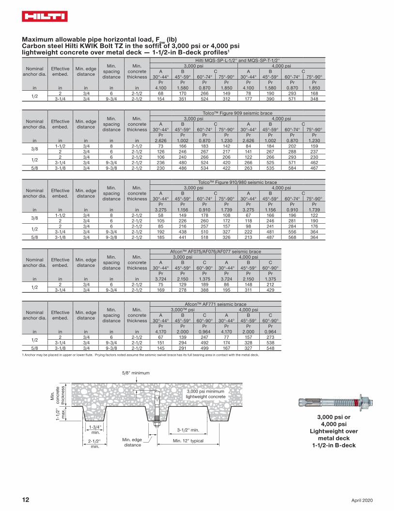
1 Anchor may be placed in upper or lower flute. Prying factors noted assume the seismic swivel brace has its full bearing area in contact with the metal deck.
3,000 psi or4,000 psi
Lightweight over metal deck 3-in W-deck
5/8" minimum
Min. 12" typical
Min. edge distance
3-7/8"min.3-7/8"
min.
3,000 psi minimumlightweight concrete
Min
. co
ncre
teth
ickn
ess
3" m
ax.
12 April 2020
Maximum allowable pipe horizontal load, Fpw (lb) Carbon steel Hilti KWIK Bolt TZ in the soffit of 3,000 psi or 4,000 psi lightweight concrete over metal deck — 1-1/2-in B-deck profiles1
Nominal anchor dia.
Effective embed.
Min. edge distance
Min. spacing distance
Min. concrete thickness
Hilti MQS-SP-L-1/2" and MQS-SP-T-1/2"3,000 psi 4,000 psi
A B C A B C30°-44° 45°-59° 60°-74° 75°-90° 30°-44° 45°-59° 60°-74° 75°-90°
Pr Pr Pr Pr Pr Pr Pr Prin in in in in 4.100 1.580 0.870 1.850 4.100 1.580 0.870 1.850
1/2 2 3/4 6 2-1/2 68 170 266 149 78 190 293 1683-1/4 3/4 9-3/4 2-1/2 154 351 524 312 177 390 571 348
Nominal anchor dia.
Effective embed.
Min. edge distance
Min. spacing distance
Min. concrete thickness
Tolco™ Figure 909 seismic brace3,000 psi 4,000 psi
A B C A B C30°-44° 45°-59° 60°-74° 75°-90° 30°-44° 45°-59° 60°-74° 75°-90°
Pr Pr Pr Pr Pr Pr Pr Prin in in in in 2.626 1.002 0.870 1.230 2.626 1.002 0.870 1.230
3/8 1-1/2 3/4 8 2-1/2 73 166 183 142 84 184 202 1592 3/4 6 2-1/2 126 246 267 217 141 267 288 237
1/2 2 3/4 6 2-1/2 106 240 266 206 122 266 293 2303-1/4 3/4 9-3/4 2-1/2 236 480 524 420 266 525 571 462
5/8 3-1/8 3/4 9-3/8 2-1/2 230 486 534 422 263 535 584 467
Nominal anchor dia.
Effective embed.
Min. edge distance
Min. spacing distance
Min. concrete thickness
Tolco™ Figure 910/980 seismic brace3,000 psi 4,000 psi
A B C A B C30°-44° 45°-59° 60°-74° 75°-90° 30°-44° 45°-59° 60°-74° 75°-90°
Pr Pr Pr Pr Pr Pr Pr Prin in in in in 3.275 1.156 0.910 1.739 3.275 1.156 0.910 1.739
3/8 1-1/2 3/4 8 2-1/2 58 149 178 108 67 166 196 1222 3/4 6 2-1/2 105 226 260 172 118 246 281 190
1/2 2 3/4 6 2-1/2 85 216 257 157 98 241 284 1763-1/4 3/4 9-3/4 2-1/2 192 438 510 327 222 481 556 364
5/8 3-1/8 3/4 9-3/8 2-1/2 185 441 518 326 213 487 568 364
Nominal anchor dia.
Effective embed.
Min. edge distance
Min. spacing distance
Min. concrete thickness
Afcon™ AF075/AF076/AF077 seismic brace3,000 psi 4,000 psi
A B C A B C30°-44° 45°-59° 60°-90° 30°-44° 45°-59° 60°-90°
Pr Pr Pr Pr Pr Prin in in in in 3.724 2.150 1.375 3.724 2.150 1.375
1/2 2 3/4 6 2-1/2 75 129 189 86 148 2123-1/4 3/4 9-3/4 2-1/2 169 278 388 195 311 429
Nominal anchor dia.
Effective embed.
Min. edge distance
Min. spacing distance
Min. concrete thickness
Afcon™ AF771 seismic brace3,000™ psi 4,000 psi
A B C A B C30°-44° 45°-59° 60°-90° 30°-44° 45°-59° 60°-90°
Pr Pr Pr Pr Pr Prin in in in in 4.170 2.000 0.964 4.170 2.000 0.964
1/2 2 3/4 6 2-1/2 67 139 247 77 157 2733-1/4 3/4 9-3/4 2-1/2 151 294 492 174 328 538
5/8 3-1/8 3/4 9-3/8 2-1/2 145 291 499 167 327 5481 Anchor may be placed in upper or lower flute. Prying factors noted assume the seismic swivel brace has its full bearing area in contact with the metal deck.
3,000 psi or4,000 psi
Lightweight over metal deck
1-1/2-in B-deck
3,000 psi minimumlightweight concreteM
in.
conc
rete
thic
knes
s
5/8" minimum
Min. 12" typicalMin. edge distance
3-1/2" min.
2-1/2" min.
1-3/4" min.
1-1/
2"
max
.

Anchorage for seismic bracing technical supplement
13April 2020
3,000 psiNWC
Maximum allowable pipe horizontal load, Fpw (lb) Hilti KCS-WF in 3,000 psi normal weight cracked concrete with Grade A36 threaded rod (or stronger)
Nominal anchor
internal dia.
Effective embed.
Min. edge distance
Min. spacing distance
Min. concrete thickness
Hilti MQS-SP-L-1/2" and MQS-SP-T-1/2"A B C D E F G H I
30°-44° 45°-59° 60°-74° 75°-90° 30°-44° 45°-59° 60°-90° 30°-44° 45°-59° 60°-90°Pr Pr Pr Pr Pr Pr Pr Pr Pr Pr
in in in in in 4.100 1.580 0.870 1.850 1.520 2.320 3.440 3.710 2.620 2.1401/2 1.63 5-3/4 5 6 151 319 459 286 264 242 180 143 202 247
Nominal anchor
internal dia.
Effective embed.
Min. edge distance
Min. spacing distance
Min. concrete thickness
Tolco™ Figure 909 seismic braceA B C D E F G H I
30°-44° 45°-59° 60°-74° 75°-90° 30°-44° 45°-59° 60°-90° 30°-44° 45°-59° 60°-90°Pr Pr Pr Pr Pr Pr Pr Pr Pr Pr
in in in in in 2.626 1.002 0.870 1.230 1.513 1.487 2.226 2.460 1.740 1.4203/8 1.11 4 3-1/2 6 124 239 258 211 149 187 156 106 149 1831/2 1.63 5-3/4 5 6 220 424 459 375 264 332 278 188 265 3255/8 1.90 6-1/2 5-3/4 6 276 532 576 471 332 417 349 236 333 4083/4 1.83 6 5-1/2 6 260 501 542 444 312 393 329 222 314 384
Nominal anchor
internal dia.
Effective embed.
Min. edge distance
Min. spacing distance
Min. concrete thickness
Tolco™ Figure 910/980 seismic braceA B C D E F G H I
30°-44° 45°-59° 60°-74° 75°-90° 30°-44° 45°-59° 60°-90° 30°-44° 45°-59° 60°-90°Pr Pr Pr Pr Pr Pr Pr Pr Pr Pr
in in in in in 3.275 1.156 0.910 1.739 1.461 1.850 2.895 3.478 2.459 2.0083/8 1.11 4 3-1/2 6 104 219 252 168 151 161 120 84 119 1451/2 1.63 5-3/4 5 6 185 390 448 299 269 286 214 149 211 2595/8 1.90 6-1/2 5-3/4 6 232 489 562 375 338 359 268 187 265 3253/4 1.83 6 5-1/2 6 218 461 529 353 318 338 253 176 250 306
Nominal anchor
internal dia.
Effective embed.
Min. edge distance
Min. spacing distance
Min. concrete thickness
Afcon™ AF075/AF076/AF077 seismic braceA B C D E F G H I
30°-44° 45°-59° 60°-90° 30°-44° 45°-59° 60°-90° 30°-44° 45°-59° 60°-90°Pr Pr Pr Pr Pr Pr Pr Pr Pr
in in in in in 3.724 2.150 1.375 2.150 2.150 2.250 2.750 1.945 1.5881/2 1.63 5-3/4 5 6 166 256 350 215 256 275 184 276 368
Nominal anchor
internal dia.
Effective embed.
Min. edge distance
Min. spacing distance
Min. concrete thickness
Afcon™ AF771 seismic braceA B C D E F G H I
30°-44° 45°-59° 60°-90° 30°-44° 45°-59° 60°-90° 30°-44° 45°-59° 60°-90°Pr Pr Pr Pr Pr Pr Pr Pr Pr
in in in in in 4.170 2.000 0.964 1.966 2.385 2.964 1.929 1.364 1.1131/2 1.63 5-3/4 5 6 148 270 434 228 237 209 230 351 4815/8 1.90 6-1/2 5-3/4 6 186 339 544 286 298 262 289 441 6033/4 1.83 6 5-1/2 6 176 319 513 269 280 247 272 416 568
Tallow Tallow
Vallow
Min. spacing1.5 x Min.
edge distance
Min
. con
c.
thic
knes
s
Min
. con
c.
thic
knes
s
Min. edge distance

14 April 2020
Maximum allowable pipe horizontal load, Fpw (lb) Hilti KCS-WF in 4,000 psi normal weight cracked concrete with Grade A36 threaded rod (or stronger)
Nominal anchor
internal dia.
Effective embed.
Min. edge distance
Min. spacing distance
Min. concrete thickness
Hilti MQS-SP-L-1/2" and MQS-SP-T-1/2"A B C D E F G H I
30°-44° 45°-59° 60°-74° 75°-90° 30°-44° 45°-59° 60°-90° 30°-44° 45°-59° 60°-90°Pr Pr Pr Pr Pr Pr Pr Pr Pr Pr
in in in in in 4.100 1.580 0.870 1.850 1.520 2.320 3.440 3.710 2.620 2.1401/2 1.63 5-3/4 5 6 174 362 517 325 297 276 208 162 230 281
Nominal anchor
internal dia.
Effective embed.
Min. edge distance
Min. spacing distance
Min. concrete thickness
Tolco™ Figure 909 seismic braceA B C D E F G H I
30°-44° 45°-59° 60°-74° 75°-90° 30°-44° 45°-59° 60°-90° 30°-44° 45°-59° 60°-90°Pr Pr Pr Pr Pr Pr Pr Pr Pr Pr
in in in in in 2.626 1.002 0.870 1.230 1.513 1.487 2.226 2.460 1.740 1.4203/8 1.11 4 3-1/2 6 142 273 295 242 170 214 181 121 171 2101/2 1.63 5-3/4 5 6 251 479 517 425 298 377 320 212 300 3685/8 1.90 6-1/2 5-3/4 6 319 615 665 544 383 482 404 272 385 4723/4 1.83 6 5-1/2 6 300 579 626 512 361 453 380 256 362 444
Nominal anchor
internal dia.
Effective embed.
Min. edge distance
Min. spacing distance
Min. concrete thickness
Tolco™ Figure 910/980 seismic braceA B C D E F G H I
30°-44° 45°-59° 60°-74° 75°-90° 30°-44° 45°-59° 60°-90° 30°-44° 45°-59° 60°-90°Pr Pr Pr Pr Pr Pr Pr Pr Pr Pr
in in in in in 3.275 1.156 0.910 1.739 1.461 1.850 2.895 3.478 2.459 2.0083/8 1.11 4 3-1/2 6 119 251 288 193 173 185 139 96 136 1671/2 1.63 5-3/4 5 6 211 441 505 339 303 325 247 170 240 2945/8 1.90 6-1/2 5-3/4 6 268 566 649 433 391 415 310 217 306 3753/4 1.83 6 5-1/2 6 252 532 611 407 367 390 292 204 288 353
Nominal anchor
internal dia.
Effective embed.
Min. edge distance
Min. spacing distance
Min. concrete thickness
Afcon™ AF075/AF076/AF077 seismic braceA B C D E F G H I
30°-44° 45°-59° 60°-90° 30°-44° 45°-59° 60°-90° 30°-44° 45°-59° 60°-90°Pr Pr Pr Pr Pr Pr Pr Pr Pr
in in in in in 3.724 2.150 1.375 2.150 2.150 2.250 2.750 1.945 1.5881/2 1.63 5-3/4 5 6 190 292 396 244 292 317 208 314 420
Nominal anchor
internal dia.
Effective embed.
Min. edge distance
Min. spacing distance
Min. concrete thickness
Afcon™ AF771 seismic braceA B C D E F G H I
30°-44° 45°-59° 60°-90° 30°-44° 45°-59° 60°-90° 30°-44° 45°-59° 60°-90°Pr Pr Pr Pr Pr Pr Pr Pr Pr
in in in in in 4.170 2.000 0.964 1.966 2.385 2.964 1.929 1.364 1.1131/2 1.63 5-3/4 5 6 171 308 489 257 270 241 260 398 5475/8 1.90 6-1/2 5-3/4 6 215 392 629 330 344 303 334 510 6973/4 1.83 6 5-1/2 6 203 369 592 311 323 285 314 480 656
4,000 psiNWC
Tallow Tallow
Vallow
Min. spacing1.5 x Min.
edge distance
Min
. con
c.
thic
knes
s
Min
. con
c.
thic
knes
s
Min. edge distance

Anchorage for seismic bracing technical supplement
15April 2020
Maximum allowable pipe horizontal load, Fpw (lb) Hilti KCS-WF in 5,000 psi normal weight cracked concrete with Grade A36 threaded rod (or stronger)
Nominal anchor
internal dia.
Effective embed.
Min. edge distance
Min. spacing distance
Min. concrete thickness
Hilti MQS-SP-L-1/2" and MQS-SP-T-1/2"A B C D E F G H I
30°-44° 45°-59° 60°-74° 75°-90° 30°-44° 45°-59° 60°-90° 30°-44° 45°-59° 60°-90°Pr Pr Pr Pr Pr Pr Pr Pr Pr Pr
in in in in in 4.100 1.580 0.870 1.850 1.520 2.320 3.440 3.710 2.620 2.1401/2 1.63 5-3/4 5 6 192 389 547 351 314 299 232 175 248 303
Nominal anchor
internal dia.
Effective embed.
Min. edge distance
Min. spacing distance
Min. concrete thickness
Tolco™ Figure 909 seismic braceA B C D E F G H I
30°-44° 45°-59° 60°-74° 75°-90° 30°-44° 45°-59° 60°-90° 30°-44° 45°-59° 60°-90°Pr Pr Pr Pr Pr Pr Pr Pr Pr Pr
in in in in in 2.626 1.002 0.870 1.230 1.513 1.487 2.226 2.460 1.740 1.4203/8 1.11 4 3-1/2 6 155 290 312 258 180 230 198 129 183 2241/2 1.63 5-3/4 5 6 273 509 547 454 315 404 350 227 321 3935/8 1.90 6-1/2 5-3/4 6 357 687 743 608 428 538 451 304 430 5273/4 1.83 6 5-1/2 6 337 650 703 575 405 509 426 287 406 498
Nominal anchor
internal dia.
Effective embed.
Min. edge distance
Min. spacing distance
Min. concrete thickness
Tolco™ Figure 910/980 seismic braceA B C D E F G H I
30°-44° 45°-59° 60°-74° 75°-90° 30°-44° 45°-59° 60°-90° 30°-44° 45°-59° 60°-90°Pr Pr Pr Pr Pr Pr Pr Pr Pr Pr
in in in in in 3.275 1.156 0.910 1.739 1.461 1.850 2.895 3.478 2.459 2.0083/8 1.11 4 3-1/2 6 130 268 305 208 183 199 155 104 147 1801/2 1.63 5-3/4 5 6 230 470 535 365 321 351 275 183 258 3175/8 1.90 6-1/2 5-3/4 6 299 632 725 484 436 463 347 242 342 4193/4 1.83 6 5-1/2 6 283 597 686 457 412 438 328 229 323 396
Nominal anchor
internal dia.
Effective embed.
Min. edge distance
Min. spacing distance
Min. concrete thickness
Afcon™ AF075/AF076/AF077 seismic braceA B C D E F G H I
30°-44° 45°-59° 60°-90° 30°-44° 45°-59° 60°-90° 30°-44° 45°-59° 60°-90°Pr Pr Pr Pr Pr Pr Pr Pr Pr
in in in in in 3.724 2.150 1.375 2.150 2.150 2.250 2.750 1.945 1.5881/2 1.63 5-3/4 5 6 208 316 424 261 316 347 224 339 457
Nominal anchor
internal dia.
Effective embed.
Min. edge distance
Min. spacing distance
Min. concrete thickness
Afcon™ AF771 seismic braceA B C D E F G H I
30°-44° 45°-59° 60°-90° 30°-44° 45°-59° 60°-90° 30°-44° 45°-59° 60°-90°Pr Pr Pr Pr Pr Pr Pr Pr Pr
in in in in in 4.170 2.000 0.964 1.966 2.385 2.964 1.929 1.364 1.1131/2 1.63 5-3/4 5 6 189 332 519 274 293 269 277 427 5905/8 1.90 6-1/2 5-3/4 6 241 438 702 369 384 338 373 569 7793/4 1.83 6 5-1/2 6 227 414 664 349 363 320 353 538 736
5,000 psiNWC
Tallow Tallow
Vallow
Min. spacing1.5 x Min.
edge distance
Min
. con
c.
thic
knes
s
Min
. con
c.
thic
knes
s
Min. edge distance

16 April 2020
Maximum allowable pipe horizontal load, Fpw (lb) Hilti KCS-WF in 6,000 psi normal weight cracked concrete with Grade A36 threaded rod (or stronger)
Nominal anchor
internal dia.
Effective embed.
Min. edge distance
Min. spacing distance
Min. concrete thickness
Hilti MQS-SP-L-1/2" and MQS-SP-T-1/2"A B C D E F G H I
30°-44° 45°-59° 60°-74° 75°-90° 30°-44° 45°-59° 60°-90° 30°-44° 45°-59° 60°-90°Pr Pr Pr Pr Pr Pr Pr Pr Pr Pr
in in in in in 4.100 1.580 0.870 1.850 1.520 2.320 3.440 3.710 2.620 2.1401/2 1.63 5-3/4 5 6 207 413 573 373 329 320 255 186 264 323
Nominal anchor
internal dia.
Effective embed.
Min. edge distance
Min. spacing distance
Min. concrete thickness
Tolco™ Figure 909 seismic braceA B C D E F G H I
30°-44° 45°-59° 60°-74° 75°-90° 30°-44° 45°-59° 60°-90° 30°-44° 45°-59° 60°-90°Pr Pr Pr Pr Pr Pr Pr Pr Pr Pr
in in in in in 2.626 1.002 0.870 1.230 1.513 1.487 2.226 2.460 1.740 1.4203/8 1.11 4 3-1/2 6 166 305 328 273 189 244 214 137 193 2371/2 1.63 5-3/4 5 6 293 534 573 479 330 428 377 239 338 4155/8 1.90 6-1/2 5-3/4 6 391 753 815 667 469 590 494 333 471 5773/4 1.83 6 5-1/2 6 368 709 767 628 442 556 466 314 444 544
Nominal anchor
internal dia.
Effective embed.
Min. edge distance
Min. spacing distance
Min. concrete thickness
Tolco™ Figure 910/980 seismic braceA B C D E F G H I
30°-44° 45°-59° 60°-74° 75°-90° 30°-44° 45°-59° 60°-90° 30°-44° 45°-59° 60°-90°Pr Pr Pr Pr Pr Pr Pr Pr Pr Pr
in in in in in 3.275 1.156 0.910 1.739 1.461 1.850 2.895 3.478 2.459 2.0083/8 1.11 4 3-1/2 6 141 283 321 221 192 213 171 111 157 1921/2 1.63 5-3/4 5 6 248 495 560 389 335 373 302 194 275 3365/8 1.90 6-1/2 5-3/4 6 328 692 795 530 478 508 380 265 375 4593/4 1.83 6 5-1/2 6 309 652 749 499 450 478 358 250 353 433
Nominal anchor
internal dia.
Effective embed.
Min. edge distance
Min. spacing distance
Min. concrete thickness
Afcon™ AF075/AF076/AF077 seismic braceA B C D E F G H I
30°-44° 45°-59° 60°-90° 30°-44° 45°-59° 60°-90° 30°-44° 45°-59° 60°-90°Pr Pr Pr Pr Pr Pr Pr Pr Pr
in in in in in 3.724 2.150 1.375 2.150 2.150 2.250 2.750 1.945 1.5881/2 1.63 5-3/4 5 6 224 337 449 275 337 374 238 361 490
Nominal anchor
internal dia.
Effective embed.
Min. edge distance
Min. spacing distance
Min. concrete thickness
Afcon™ AF771 seismic braceA B C D E F G H I
30°-44° 45°-59° 60°-90° 30°-44° 45°-59° 60°-90° 30°-44° 45°-59° 60°-90°Pr Pr Pr Pr Pr Pr Pr Pr Pr
in in in in in 4.170 2.000 0.964 1.966 2.385 2.964 1.929 1.364 1.1131/2 1.63 5-3/4 5 6 205 354 545 289 314 295 292 451 6295/8 1.90 6-1/2 5-3/4 6 264 480 770 404 421 371 409 624 8543/4 1.83 6 5-1/2 6 249 452 725 381 397 350 385 588 804
6,000 psiNWC
Tallow Tallow
Vallow
Min. spacing1.5 x Min.
edge distance
Min
. con
c.
thic
knes
s
Min
. con
c.
thic
knes
s
Min. edge distance

Anchorage for seismic bracing technical supplement
17April 2020
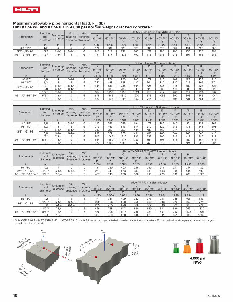
Maximum allowable pipe horizontal load, Fpw (lb) Hilti KCM-WF and KCM-PD in 3,000 psi normal weight cracked concrete 1
Anchor sizeNominal
rod diameter
Min. edge distance
Min. spacing distance
Min. concrete thickness
Hilti MQS-SP-L-1/2" and MQS-SP-T-1/2"A B C D E F G H I
30°-44° 45°-59° 60°-74° 75°-90° 30°-44° 45°-59° 60°-90° 30°-44° 45°-59° 60°-90°Pr Pr Pr Pr Pr Pr Pr Pr Pr Pr
in in in in in 4.100 1.580 0.870 1.850 1.520 2.320 3.440 3.710 2.620 2.1403/8"-1/2" 1/2 4 5 6 150 317 456 284 262 241 179 142 201 246
3/8"-1/2"-5/8" 1/2 (1) 5-1/4 6-1/4 6 210 444 639 398 367 337 251 199 281 3443/8"-1/2"-5/8"-3/4" 1/2 (1) 7-3/4 9 6 376 797 1149 714 660 604 448 356 504 618
Anchor sizeNominal
rod diameter
Min. edge distance
Min. spacing distance
Min. concrete thickness
Tolco™ Figure 909 seismic braceA B C D E F G H I
30°-44° 45°-59° 60°-74° 75°-90° 30°-44° 45°-59° 60°-90° 30°-44° 45°-59° 60°-90°Pr Pr Pr Pr Pr Pr Pr Pr Pr Pr
in in in in in 2.626 1.002 0.870 1.230 1.513 1.487 2.226 2.460 1.740 1.4201/4"-3/8" 3/8 4 3-1/2 6 124 240 259 212 149 188 157 106 150 1843/8"-1/2" 1/2 4 5 6 219 422 456 373 263 331 277 187 264 323
3/8"-1/2"-5/8" 1/2 (1) 5-1/4 6-1/4 6 307 591 639 523 368 463 388 261 370 453 5/8 5-1/4 6-1/4 6 307 591 639 523 368 463 388 261 370 453
3/8"-1/2"-5/8"-3/4"1/2 (1) 7-3/4 9 6 549 1062 1149 939 662 830 693 469 664 8135/8 (1) 7-3/4 9 6 587 1261 1386 1092 798 948 693 546 772 945 3/4 7-3/4 9 8 560 1102 1196 970 689 855 693 485 686 840
Anchor sizeNominal
rod diameter
Min. edge distance
Min. spacing distance
Min. concrete thickness
Tolco™ Figure 910/980 seismic braceA B C D E F G H I
30°-44° 45°-59° 60°-74° 75°-90° 30°-44° 45°-59° 60°-90° 30°-44° 45°-59° 60°-90°Pr Pr Pr Pr Pr Pr Pr Pr Pr Pr
in in in in in 3.275 1.156 0.910 1.739 1.461 1.850 2.895 3.478 2.459 2.0081/4"-3/8" 3/8 4 3-1/2 6 104 220 253 169 152 162 121 84 119 1463/8"-1/2" 1/2 4 5 6 184 388 445 297 268 284 213 149 210 257
3/8"-1/2"-5/8" 1/2 (1) 5-1/4 6-1/4 6 257 543 624 416 375 398 298 208 294 360 5/8 5-1/4 6-1/4 6 257 543 624 416 375 398 298 208 294 360
3/8"-1/2"-5/8"-3/4"1/2 (1) 7-3/4 9 6 461 975 1121 746 674 714 532 373 528 6465/8 (1) 7-3/4 9 6 471 1141 1346 839 816 799 532 420 594 727 3/4 7-3/4 9 8 468 1009 1166 766 702 732 532 383 541 663
Anchor sizeNominal
rod diameter
Min. edge distance
Min. spacing distance
Min. concrete thickness
Afcon™ AF075/AF076/AF077 seismic braceA B C D E F G H I
30°-44° 45°-59° 60°-90° 30°-44° 45°-59° 60°-90° 30°-44° 45°-59° 60°-90°Pr Pr Pr Pr Pr Pr Pr Pr Pr
in in in in in 3.724 2.150 1.375 2.150 2.150 2.250 2.750 1.945 1.5883/8"-1/2" 1/2 4 5 6 165 255 348 214 255 274 183 274 366
3/8"-1/2"-5/8" 1/2 (1) 5-1/4 6-1/4 6 231 357 487 300 357 383 256 384 5123/8"-1/2"-5/8"-3/4" 1/2 (1) 7-3/4 9 6 414 640 874 539 640 685 459 689 918
Anchor sizeNominal
rod diameter
Min. edge distance
Min. spacing distance
Min. concrete thickness
Afcon™ AF771 seismic braceA B C D E F G H I
30°-44° 45°-59° 60°-90° 30°-44° 45°-59° 60°-90° 30°-44° 45°-59° 60°-90°Pr Pr Pr Pr Pr Pr Pr Pr Pr
in in in in in 4.170 2.000 0.964 1.966 2.385 2.964 1.929 1.364 1.1133/8"-1/2" 1/2 4 5 6 148 269 431 226 236 208 229 350 478
3/8"-1/2"-5/8" 1/2 (1) 5-1/4 6-1/4 6 207 376 604 317 330 291 321 490 670 5/8 5-1/4 6-1/4 6 207 376 604 317 330 291 321 490 670
3/8"-1/2"-5/8"-3/4"1/2 (1) 7-3/4 9 6 370 675 1085 569 592 520 576 879 12015/8 (1) 7-3/4 9 6 414 707 1006 668 646 520 677 1012 1339 3/4 7-3/4 9 8 414 654 901 589 604 520 596 906 1230
1 Only ASTM A193 Grade B7, ASTM A325, or ASTM F1554 Grade 105 threaded rod is permitted with smaller interior thread diameter. A36 threaded rod (or stronger) can be used with largest thread diameter per insert.
3,000 psiNWC
Tallow Tallow
Vallow
Min. spacing1.5 x Min.
edge distance
Min
. con
c.
thic
knes
s
Min
. con
c.
thic
knes
s
Min. edge distance
18 April 2020
Maximum allowable pipe horizontal load, Fpw (lb) Hilti KCM-WF and KCM-PD in 4,000 psi normal weight cracked concrete 1
Anchor sizeNominal
rod diameter
Min. edge distance
Min. spacing distance
Min. concrete thickness
Hilti MQS-SP-L-1/2" and MQS-SP-T-1/2"A B C D E F G H I
30°-44° 45°-59° 60°-74° 75°-90° 30°-44° 45°-59° 60°-90° 30°-44° 45°-59° 60°-90°Pr Pr Pr Pr Pr Pr Pr Pr Pr Pr
in in in in in 4.100 1.580 0.870 1.850 1.520 2.320 3.440 3.710 2.620 2.1403/8"-1/2" 1/2 4 5 6 174 367 528 329 303 279 207 164 232 285
3/8"-1/2"-5/8" 1/2 (1) 5-1/4 6-1/4 6 243 513 738 460 424 390 290 230 325 3983/8"-1/2"-5/8"-3/4" 1/2 (1) 7-3/4 9 6 431 877 1238 790 712 673 518 394 558 683
Anchor sizeNominal
rod diameter
Min. edge distance
Min. spacing distance
Min. concrete thickness
Tolco™ Figure 909 seismic braceA B C D E F G H I
30°-44° 45°-59° 60°-74° 75°-90° 30°-44° 45°-59° 60°-90° 30°-44° 45°-59° 60°-90°Pr Pr Pr Pr Pr Pr Pr Pr Pr Pr
in in in in in 2.626 1.002 0.870 1.230 1.513 1.487 2.226 2.460 1.740 1.4201/4"-3/8" 3/8 4 3-1/2 6 143 274 296 243 171 215 182 122 172 2103/8"-1/2" 1/2 4 5 6 253 488 528 432 304 382 320 216 305 374
3/8"-1/2"-5/8" 1/2 (1) 5-1/4 6-1/4 6 354 683 738 604 425 535 448 302 427 523 5/8 5-1/4 6-1/4 6 354 683 738 604 425 535 448 302 427 523
3/8"-1/2"-5/8"-3/4"1/2 (1) 7-3/4 9 6 614 1150 1238 1024 713 912 785 512 724 8875/8 (1) 7-3/4 9 6 675 1388 1519 1209 875 1056 800 605 855 1047 3/4 7-3/4 9 8 627 1198 1293 1062 745 942 798 531 751 920
Anchor sizeNominal
rod diameter
Min. edge distance
Min. spacing distance
Min. concrete thickness
Tolco™ Figure 910/980 seismic braceA B C D E F G H I
30°-44° 45°-59° 60°-74° 75°-90° 30°-44° 45°-59° 60°-90° 30°-44° 45°-59° 60°-90°Pr Pr Pr Pr Pr Pr Pr Pr Pr Pr
in in in in in 3.275 1.156 0.910 1.739 1.461 1.850 2.895 3.478 2.459 2.0081/4"-3/8" 3/8 4 3-1/2 6 120 252 289 194 174 185 140 97 137 1683/8"-1/2" 1/2 4 5 6 213 449 515 344 310 329 246 172 243 298
3/8"-1/2"-5/8" 1/2 (1) 5-1/4 6-1/4 6 297 627 720 481 433 460 344 240 340 416 5/8 5-1/4 6-1/4 6 297 627 720 481 433 460 344 240 340 416
3/8"-1/2"-5/8"-3/4"1/2 (1) 7-3/4 9 6 517 1062 1210 823 726 790 615 412 582 7135/8 (1) 7-3/4 9 6 544 1262 1477 939 894 895 615 469 664 813 3/4 7-3/4 9 8 527 1102 1263 847 759 812 615 424 599 734
Anchor sizeNominal
rod diameter
Min. edge distance
Min. spacing distance
Min. concrete thickness
Afcon ™AF075/AF076/AF077 seismic braceA B C D E F G H I
30°-44° 45°-59° 60°-90° 30°-44° 45°-59° 60°-90° 30°-44° 45°-59° 60°-90°Pr Pr Pr Pr Pr Pr Pr Pr Pr
in in in in in 3.724 2.150 1.375 2.150 2.150 2.250 2.750 1.945 1.5883/8"-1/2" 1/2 4 5 6 191 295 403 248 295 317 211 317 423
3/8"-1/2"-5/8" 1/2 (1) 5-1/4 6-1/4 6 267 412 563 347 412 443 295 444 5923/8"-1/2"-5/8"-3/4" 1/2 (1) 7-3/4 9 6 467 710 958 588 710 779 505 763 1026
Anchor sizeNominal
rod diameter
Min. edge distance
Min. spacing distance
Min. concrete thickness
Afcon™ AF771 seismic braceA B C D E F G H I
30°-44° 45°-59° 60°-90° 30°-44° 45°-59° 60°-90° 30°-44° 45°-59° 60°-90°Pr Pr Pr Pr Pr Pr Pr Pr Pr
in in in in in 4.170 2.000 0.964 1.966 2.385 2.964 1.929 1.364 1.1133/8"-1/2" 1/2 4 5 6 171 311 499 262 273 241 265 405 553
3/8"-1/2"-5/8" 1/2 (1) 5-1/4 6-1/4 6 239 435 698 366 382 336 370 566 774 5/8 5-1/4 6-1/4 6 239 435 698 366 382 336 370 566 774
3/8"-1/2"-5/8"-3/4"1/2 (1) 7-3/4 9 6 425 748 1174 620 659 601 626 963 13305/8 (1) 7-3/4 9 6 478 795 1117 738 731 601 747 1123 1501 3/4 7-3/4 9 8 474 729 990 643 675 601 651 996 1365
1 Only ASTM A193 Grade B7, ASTM A325, or ASTM F1554 Grade 105 threaded rod is permitted with smaller interior thread diameter. A36 threaded rod (or stronger) can be used with largest thread diameter per insert.
4,000 psiNWC
Tallow Tallow
Vallow
Min. spacing1.5 x Min.
edge distance
Min
. con
c.
thic
knes
s
Min
. con
c.
thic
knes
s
Min. edge distance

Anchorage for seismic bracing technical supplement
19April 2020
Maximum allowable pipe horizontal load, Fpw (lb) Hilti KCM-WF and KCM-PD in 5,000 psi normal weight cracked concrete 1
Anchor sizeNominal
rod diameter
Min. edge distance
Min. spacing distance
Min. concrete thickness
Hilti MQS-SP-L-1/2" and MQS-SP-T-1/2"A B C D E F G H I
30°-44° 45°-59° 60°-74° 75°-90° 30°-44° 45°-59° 60°-90° 30°-44° 45°-59° 60°-90°Pr Pr Pr Pr Pr Pr Pr Pr Pr Pr
in in in in in 4.100 1.580 0.870 1.850 1.520 2.320 3.440 3.710 2.620 2.1403/8"-1/2" 1/2 4 5 6 194 398 564 358 324 304 232 178 253 309
3/8"-1/2"-5/8" 1/2 (1) 5-1/4 6-1/4 6 272 575 827 515 475 436 325 257 364 4463/8"-1/2"-5/8"-3/4" 1/2 (1) 7-3/4 9 6 472 942 1308 851 752 729 579 425 601 736
Anchor sizeNominal
rod diameter
Min. edge distance
Min. spacing distance
Min. concrete thickness
Tolco™ Figure 909 seismic braceA B C D E F G H I
30°-44° 45°-59° 60°-74° 75°-90° 30°-44° 45°-59° 60°-90° 30°-44° 45°-59° 60°-90°Pr Pr Pr Pr Pr Pr Pr Pr Pr Pr
in in in in in 2.626 1.002 0.870 1.230 1.513 1.487 2.226 2.460 1.740 1.4201/4"-3/8" 3/8 4 3-1/2 6 156 292 315 260 181 232 200 130 184 2263/8"-1/2" 1/2 4 5 6 277 523 564 465 325 414 354 233 329 403
3/8"-1/2"-5/8" 1/2 (1) 5-1/4 6-1/4 6 397 765 827 677 476 599 501 338 478 586 5/8 5-1/4 6-1/4 6 397 765 827 677 476 599 501 338 478 586
3/8"-1/2"-5/8"-3/4"1/2 (1) 7-3/4 9 6 667 1220 1308 1093 754 978 860 546 773 9465/8 (1) 7-3/4 9 6 741 1491 1625 1305 936 1145 894 653 923 1131 3/4 7-3/4 9 8 683 1273 1370 1135 789 1012 875 568 803 983
Anchor sizeNominal
rod diameter
Min. edge distance
Min. spacing distance
Min. concrete thickness
Tolco™ Figure 910/980 seismic braceA B C D E F G H I
30°-44° 45°-59° 60°-74° 75°-90° 30°-44° 45°-59° 60°-90° 30°-44° 45°-59° 60°-90°Pr Pr Pr Pr Pr Pr Pr Pr Pr Pr
in in in in in 3.275 1.156 0.910 1.739 1.461 1.850 2.895 3.478 2.459 2.0081/4"-3/8" 3/8 4 3-1/2 6 132 270 307 209 184 201 157 105 148 1813/8"-1/2" 1/2 4 5 6 233 483 551 373 331 358 275 186 264 323
3/8"-1/2"-5/8" 1/2 (1)) 5-1/4 6-1/4 6 333 703 807 538 485 515 386 269 381 466 5/8 5-1/4 6-1/4 6 333 703 807 538 485 515 386 269 381 466
3/8"-1/2"-5/8"-3/4"1/2 (1)) 7-3/4 9 6 565 1131 1280 886 766 851 688 443 627 7685/8 (1)) 7-3/4 9 6 608 1360 1582 1021 955 975 688 511 722 884 3/4 7-3/4 9 8 576 1177 1339 914 803 877 688 457 646 792
Anchor sizeNominal
rod diameter
Min. edge distance
Min. spacing distance
Min. concrete thickness
Afcon™ AF075/AF076/AF077 seismic braceA B C D E F G H I
30°-44° 45°-59° 60°-90° 30°-44° 45°-59° 60°-90° 30°-44° 45°-59° 60°-90°Pr Pr Pr Pr Pr Pr Pr Pr Pr
in in in in in 3.724 2.150 1.375 2.150 2.150 2.250 2.750 1.945 1.5883/8"-1/2" 1/2 4 5 6 210 321 435 267 321 351 229 345 463
3/8"-1/2"-5/8" 1/2 (1)) 5-1/4 6-1/4 6 299 462 630 388 462 496 331 497 6633/8"-1/2"-5/8"-3/4" 1/2 (1) 7-3/4 9 6 510 769 1025 628 769 853 542 823 1116
Anchor sizeNominal
rod diameter
Min. edge distance
Min. spacing distance
Min. concrete thickness
Afcon™ AF771 seismic braceA B C D E F G H I
30°-44° 45°-59° 60°-90° 30°-44° 45°-59° 60°-90° 30°-44° 45°-59° 60°-90°Pr Pr Pr Pr Pr Pr Pr Pr Pr
in in in in in 4.170 2.000 0.964 1.966 2.385 2.964 1.929 1.364 1.1133/8"-1/2" 1/2 4 5 6 191 339 534 282 298 269 285 437 602
3/8"-1/2"-5/8" 1/2 (1)) 5-1/4 6-1/4 6 268 487 781 410 427 377 415 634 866 5/8 5-1/4 6-1/4 6 268 487 781 410 427 377 415 634 866
3/8"-1/2"-5/8"-3/4"1/2 (1) 7-3/4 9 6 466 808 1244 660 715 672 666 1030 14355/8 (1) 7-3/4 9 6 535 869 1210 795 800 672 805 1216 1637 3/4 7-3/4 9 8 520 790 1062 686 733 672 694 1067 1477
1 Only ASTM A193 Grade B7, ASTM A325, or ASTM F1554 Grade 105 threaded rod is permitted with smaller interior thread diameter. A36 threaded rod (or stronger) can be used with largest thread diameter per insert.
5,000 psiNWC
Tallow Tallow
Vallow
Min. spacing1.5 x Min.
edge distance
Min
. con
c.
thic
knes
s
Min
. con
c.
thic
knes
s
Min. edge distance

20 April 2020
Maximum allowable pipe horizontal load, Fpw (lb) Hilti KCM-WF and KCM-PD in 6,000 psi normal weight cracked concrete 1
Anchor sizeNominal
rod diameter
Min. edge distance
Min. spacing distance
Min. concrete thickness
Hilti MQS-SP-L-1/2" and MQS-SP-T-1/2"A B C D E F G H I
30°-44° 45°-59° 60°-74° 75°-90° 30°-44° 45°-59° 60°-90° 30°-44° 45°-59° 60°-90°Pr Pr Pr Pr Pr Pr Pr Pr Pr Pr
in in in in in 4.100 1.580 0.870 1.850 1.520 2.320 3.440 3.710 2.620 2.1403/8"-1/2" 1/2 4 5 6 209 422 590 380 339 325 254 190 269 329
3/8"-1/2"-5/8" 1/2 (1) 5-1/4 6-1/4 6 298 629 905 564 520 477 355 281 398 4883/8"-1/2"-5/8"-3/4" 1/2 (1) 7-3/4 9 6 508 996 1364 903 785 777 634 451 638 781
Anchor sizeNominal
rod diameter
Min. edge distance
Min. spacing distance
Min. concrete thickness
Tolco™ Figure 909 seismic braceA B C D E F G H I
30°-44° 45°-59° 60°-74° 75°-90° 30°-44° 45°-59° 60°-90° 30°-44° 45°-59° 60°-90°Pr Pr Pr Pr Pr Pr Pr Pr Pr Pr
in in in in in 2.626 1.002 0.870 1.230 1.513 1.487 2.226 2.460 1.740 1.4201/4"-3/8" 3/8 4 3-1/2 6 167 306 328 274 189 245 215 137 194 2373/8"-1/2" 1/2 4 5 6 297 549 590 491 340 438 381 245 347 425
3/8"-1/2"-5/8" 1/2 (1) 5-1/4 6-1/4 6 434 837 905 740 521 655 548 370 523 641 5/8 5-1/4 6-1/4 6 428 816 880 724 507 642 546 362 512 627
3/8"-1/2"-5/8"-3/4"1/2 (1) 7-3/4 9 6 712 1277 1364 1149 786 1032 924 574 812 9955/8 (1) 7-3/4 9 6 797 1577 1713 1386 987 1220 979 693 980 1201 3/4 7-3/4 9 8 730 1335 1432 1196 825 1070 941 598 846 1036
Anchor sizeNominal
rod diameter
Min. edge distance
Min. spacing distance
Min. concrete thickness
Tolco™ Figure 910/980 seismic braceA B C D E F G H I
30°-44° 45°-59° 60°-74° 75°-90° 30°-44° 45°-59° 60°-90° 30°-44° 45°-59° 60°-90°Pr Pr Pr Pr Pr Pr Pr Pr Pr Pr
in in in in in 3.275 1.156 0.910 1.739 1.461 1.850 2.895 3.478 2.459 2.0081/4"-3/8" 3/8 4 3-1/2 6 141 283 321 222 192 213 171 111 157 1923/8"-1/2" 1/2 4 5 6 251 508 577 396 346 380 301 198 280 343
3/8"-1/2"-5/8" 1/2 (1) 5-1/4 6-1/4 6 364 769 883 589 531 564 422 294 416 510 5/8 5-1/4 6-1/4 6 360 751 860 578 516 554 422 289 409 501
3/8"-1/2"-5/8"-3/4"1/2 (1) 7-3/4 9 6 605 1187 1337 939 799 903 748 469 664 8135/8 (1) 7-3/4 9 6 665 1443 1669 1092 1006 1043 753 546 772 945 3/4 7-3/4 9 8 618 1238 1401 970 839 932 753 485 686 840
Anchor sizeNominal
rod diameter
Min. edge distance
Min. spacing distance
Min. concrete thickness
Afcon™ AF075/AF076/AF077 seismic braceA B C D E F G H I
30°-44° 45°-59° 60°-90° 30°-44° 45°-59° 60°-90° 30°-44° 45°-59° 60°-90°Pr Pr Pr Pr Pr Pr Pr Pr Pr
in in in in in 3.724 2.150 1.375 2.150 2.150 2.250 2.750 1.945 1.5883/8"-1/2" 1/2 4 5 6 226 343 459 282 343 378 243 368 496
3/8"-1/2"-5/8" 1/2 (1) 5-1/4 6-1/4 6 328 505 690 425 505 543 362 544 7253/8"-1/2"-5/8"-3/4" 1/2 (1) 7-3/4 9 6 548 818 1080 660 818 916 573 874 1193
Anchor sizeNominal
rod diameter
Min. edge distance
Min. spacing distance
Min. concrete thickness
Afcon™ AF771 seismic braceA B C D E F G H I
30°-44° 45°-59° 60°-90° 30°-44° 45°-59° 60°-90° 30°-44° 45°-59° 60°-90°Pr Pr Pr Pr Pr Pr Pr Pr Pr
in in in in in 4.170 2.000 0.964 1.966 2.385 2.964 1.929 1.364 1.1133/8"-1/2" 1/2 4 5 6 206 361 561 296 318 294 300 462 640
3/8"-1/2"-5/8" 1/2 (1) 5-1/4 6-1/4 6 293 533 855 449 467 412 454 693 948 5/8 5-1/4 6-1/4 6 293 524 833 438 461 412 443 679 932
3/8"-1/2"-5/8"-3/4"1/2 (1) 7-3/4 9 6 501 859 1301 692 762 733 699 1085 15235/8 (1) 7-3/4 9 6 585 932 1287 843 860 736 853 1294 1753 3/4 7-3/4 9 8 559 842 1122 722 783 736 729 1127 1570
1 Only ASTM A193 Grade B7, ASTM A325, or ASTM F1554 Grade 105 threaded rod is permitted with smaller interior thread diameter. A36 threaded rod (or stronger) can be used with largest thread diameter per insert.
6,000 psiNWC
Tallow Tallow
Vallow
Min. spacing1.5 x Min.
edge distance
Min
. con
c.
thic
knes
s
Min
. con
c.
thic
knes
s
Min. edge distance
Anchorage for seismic bracing technical supplement
21April 2020
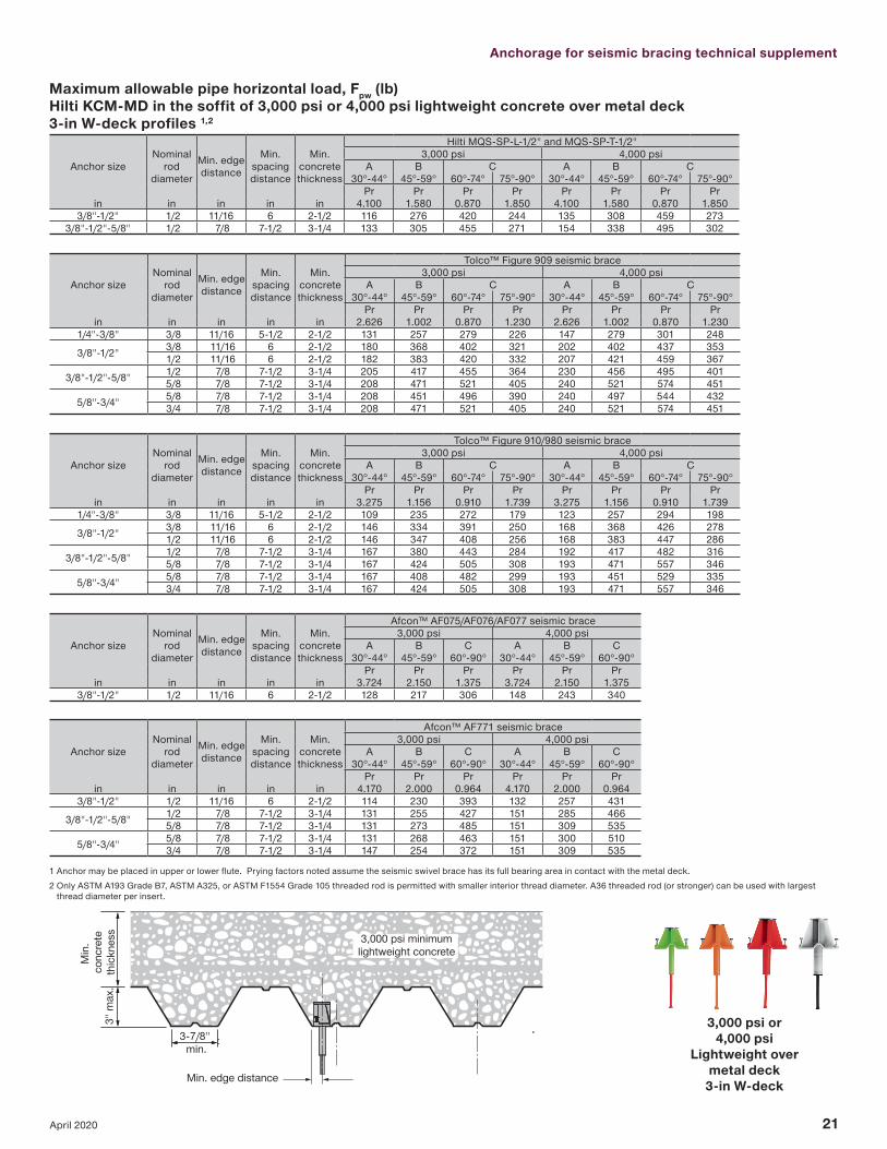
Maximum allowable pipe horizontal load, Fpw (lb) Hilti KCM-MD in the soffit of 3,000 psi or 4,000 psi lightweight concrete over metal deck 3-in W-deck profiles 1,2
Anchor sizeNominal
rod diameter
Min. edge distance
Min. spacing distance
Min. concrete thickness
Hilti MQS-SP-L-1/2" and MQS-SP-T-1/2"3,000 psi 4,000 psi
A B C A B C30°-44° 45°-59° 60°-74° 75°-90° 30°-44° 45°-59° 60°-74° 75°-90°
Pr Pr Pr Pr Pr Pr Pr Prin in in in in 4.100 1.580 0.870 1.850 4.100 1.580 0.870 1.850
3/8"-1/2" 1/2 11/16 6 2-1/2 116 276 420 244 135 308 459 2733/8"-1/2"-5/8" 1/2 7/8 7-1/2 3-1/4 133 305 455 271 154 338 495 302
Anchor sizeNominal
rod diameter
Min. edge distance
Min. spacing distance
Min. concrete thickness
Tolco™ Figure 909 seismic brace3,000 psi 4,000 psi
A B C A B C30°-44° 45°-59° 60°-74° 75°-90° 30°-44° 45°-59° 60°-74° 75°-90°
Pr Pr Pr Pr Pr Pr Pr Prin in in in in 2.626 1.002 0.870 1.230 2.626 1.002 0.870 1.230
1/4"-3/8" 3/8 11/16 5-1/2 2-1/2 131 257 279 226 147 279 301 248
3/8"-1/2" 3/8 11/16 6 2-1/2 180 368 402 321 202 402 437 353 1/2 11/16 6 2-1/2 182 383 420 332 207 421 459 367
3/8"-1/2"-5/8" 1/2 7/8 7-1/2 3-1/4 205 417 455 364 230 456 495 401 5/8 7/8 7-1/2 3-1/4 208 471 521 405 240 521 574 451
5/8"-3/4" 5/8 7/8 7-1/2 3-1/4 208 451 496 390 240 497 544 432 3/4 7/8 7-1/2 3-1/4 208 471 521 405 240 521 574 451
Anchor sizeNominal
rod diameter
Min. edge distance
Min. spacing distance
Min. concrete thickness
Tolco™ Figure 910/980 seismic brace3,000 psi 4,000 psi
A B C A B C30°-44° 45°-59° 60°-74° 75°-90° 30°-44° 45°-59° 60°-74° 75°-90°
Pr Pr Pr Pr Pr Pr Pr Prin in in in in 3.275 1.156 0.910 1.739 3.275 1.156 0.910 1.739
1/4"-3/8" 3/8 11/16 5-1/2 2-1/2 109 235 272 179 123 257 294 198
3/8"-1/2" 3/8 11/16 6 2-1/2 146 334 391 250 168 368 426 278 1/2 11/16 6 2-1/2 146 347 408 256 168 383 447 286
3/8"-1/2"-5/8" 1/2 7/8 7-1/2 3-1/4 167 380 443 284 192 417 482 316 5/8 7/8 7-1/2 3-1/4 167 424 505 308 193 471 557 346
5/8"-3/4" 5/8 7/8 7-1/2 3-1/4 167 408 482 299 193 451 529 335 3/4 7/8 7-1/2 3-1/4 167 424 505 308 193 471 557 346
Anchor sizeNominal
rod diameter
Min. edge distance
Min. spacing distance
Min. concrete thickness
Afcon™ AF075/AF076/AF077 seismic brace3,000 psi 4,000 psi
A B C A B C30°-44° 45°-59° 60°-90° 30°-44° 45°-59° 60°-90°
Pr Pr Pr Pr Pr Prin in in in in 3.724 2.150 1.375 3.724 2.150 1.375
3/8"-1/2" 1/2 11/16 6 2-1/2 128 217 306 148 243 340
Anchor sizeNominal
rod diameter
Min. edge distance
Min. spacing distance
Min. concrete thickness
Afcon™ AF771 seismic brace3,000 psi 4,000 psi
A B C A B C30°-44° 45°-59° 60°-90° 30°-44° 45°-59° 60°-90°
Pr Pr Pr Pr Pr Prin in in in in 4.170 2.000 0.964 4.170 2.000 0.964
3/8"-1/2" 1/2 11/16 6 2-1/2 114 230 393 132 257 431
3/8"-1/2"-5/8" 1/2 7/8 7-1/2 3-1/4 131 255 427 151 285 466 5/8 7/8 7-1/2 3-1/4 131 273 485 151 309 535
5/8"-3/4" 5/8 7/8 7-1/2 3-1/4 131 268 463 151 300 510 3/4 7/8 7-1/2 3-1/4 147 254 372 151 309 535
1 Anchor may be placed in upper or lower flute. Prying factors noted assume the seismic swivel brace has its full bearing area in contact with the metal deck.2 Only ASTM A193 Grade B7, ASTM A325, or ASTM F1554 Grade 105 threaded rod is permitted with smaller interior thread diameter. A36 threaded rod (or stronger) can be used with largest
thread diameter per insert.
3,000 psi or4,000 psi
Lightweight over metal deck 3-in W-deckMin. edge distance
3-7/8" min.
3,000 psi minimumlightweight concrete
Min
. co
ncre
teth
ickn
ess
3" m
ax.

22 April 2020
3,000 psi minimumlightweight concreteM
in.
conc
rete
thic
knes
s1-
1/2"
m
ax.
Min. edge distance2-1/2" min.
1-3/4" min.
Maximum allowable pipe horizontal load, Fpw (lb) Hilti KCM-MD in the soffit of 3,000 psi or 4,000 psi lightweight concrete over metal deck 1-1/2-in B-deck profiles 1,2
Anchor sizeNominal
rod diameter
Min. edge distance
Min. spacing distance
Min. concrete thickness
Hilti MQS-SP-L-1/2" and MQS-SP-T-1/2"3,000 psi 4,000 psi
A B C A B C30°-44° 45°-59° 60°-74° 75°-90° 30°-44° 45°-59° 60°-74° 75°-90°
Pr Pr Pr Pr Pr Pr Pr Prin in in in in 4.100 1.580 0.870 1.850 4.100 1.580 0.870 1.850
3/8"-1/2" 1/2 7/8 6 2-1/2 40 103 187 88 46 119 212 102
Anchor sizeNominal
rod diameter
Min. edge distance
Min. spacing distance
Min. concrete thickness
Tolco™ Figure 909 seismic brace3,000 psi 4,000 psi
A B C A B C30°-44° 45°-59° 60°-74° 75°-90° 30°-44° 45°-59° 60°-74° 75°-90°
Pr Pr Pr Pr Pr Pr Pr Prin in in in in 2.626 1.002 0.870 1.230 2.626 1.002 0.870 1.230
1/4"-3/8" 3/8 7/8 5-1/2 2-1/2 60 144 161 123 69 161 179 1383/8"-1/2" 1/2 7/8 6 2-1/2 62 163 187 132 72 188 212 153
3/8"-1/2"-5/8" 5/8 7/8 7-1/2 3-1/4 68 179 206 146 79 206 237 1685/8"-3/4" 3 3/4 7/8 7-1/2 3-1/4 449 932 1020 810 507 1021 1113 894
Anchor sizeNominal
rod diameter
Min. edge distance
Min. spacing distance
Min. concrete thickness
Tolco™ Figure 910/980 seismic brace3,000 psi 4,000 psi
A B C A B C30°-44° 45°-59° 60°-74° 75°-90° 30°-44° 45°-59° 60°-74° 75°-90°
Pr Pr Pr Pr Pr Pr Pr Prin in in in in 3.275 1.156 0.910 1.739 3.275 1.156 0.910 1.739
1/4"-3/8" 3/8 7/8 5-1/2 2-1/2 48 129 156 90 55 145 173 1043/8"-1/2" 1/2 7/8 6 2-1/2 50 141 179 94 58 163 205 108
3/8"-1/2"-5/8" 5/8 7/8 7-1/2 3-1/4 55 155 197 103 63 179 227 1195/8"-3/4" 3 3/4 7/8 7-1/2 3-1/4 360 846 992 627 416 932 1084 699
Anchor sizeNominal
rod diameter
Min. edge distance
Min. spacing distance
Min. concrete thickness
Afcon™ AF075/AF076/AF077 seismic brace3,000 psi 4,000 psi
A B C A B C30°-44° 45°-59° 60°-90° 30°-44° 45°-59° 60°-90°
Pr Pr Pr Pr Pr Prin in in in in 3.724 2.150 1.375 3.724 2.150 1.375
3/8"-1/2" 1/2 7/8 6 2-1/2 44 76 118 51 88 137
Anchor sizeNominal
rod diameter
Min. edge distance
Min. spacing distance
Min. concrete thickness
Afcon™ AF771 seismic brace3,000 psi 4,000 psi
A B C A B C30°-44° 45°-59° 60°-90° 30°-44° 45°-59° 60°-90°
Pr Pr Pr Pr Pr Prin in in in in 4.170 2.000 0.964 4.170 2.000 0.964
3/8"-1/2" 1/2 7/8 6 2-1/2 39 81 169 45 94 1953/8"-1/2"-5/8" 5/8 7/8 7-1/2 3-1/4 43 89 186 49 103 214
5/8"-3/4" 3 3/4 7/8 7-1/2 3-1/4 317 531 748 327 629 10461 Anchor may be placed in upper or lower flute. Prying factors noted assume the seismic swivel brace has its full bearing area in contact with the metal deck.2 Only ASTM A193 Grade B7, ASTM A325, or ASTM F1554 Grade 105 threaded rod is permitted with smaller interior thread diameter. A36 threaded rod (or stronger) can be used with largest
thread diameter per insert. 3 5/8” - 3/4” only applicable for upper flute location.
3,000 psi or4,000 psi
Lightweight over metal deck
1-1/2-in B-deck

Anchorage for seismic bracing technical supplement
23April 2020
DB
S •
04/2
0
In the US: Hilti, Inc. 7250 Dallas Parkway, Suite 1000, Dallas, TX 75024Customer Service: 1-800-879-8000en español: 1-800-879-5000Fax: 1-800-879-7000
www.hilti.com
Hilti is an equal opportunity employer.Hilti is a registered trademark of Hilti, Corp.©Copyright 2020 by Hilti, Inc. (U.S.)
The data contained in this literature was current as of the date of publication. Updates and changes may be made based on later testing. If verification is needed that the data is still current, please contact the Hilti Technical Support Specialists at 1-800-879-8000. All published load values contained in this literature represent the results of testing by Hilti or test organizations. Local base materials were used. Because of variations in materials, on-site testing is necessary to determine performance at any specific site. Laser beams represented by red lines in this publication. Printed in the United States.
*14001 US only
In Canada: Hilti (Canada) Corporation2360 Meadowpine Blvd. Mississauga, Ontario, L5N 6S2 Customer Service: 1-800-363-4458 Fax: 1-800-363-4459
www.hilti.ca