“mech 4240 critical design review - auburn universitydbeale/mech4240-50/reports/excavator...
TRANSCRIPT

“MECH 4240
Corp_
MECH 4240 Critical Design Review
Summer 2011
Corp_2 – Lunar Excavator
June 29, 2011
Group Members Anna Holland Kyle Otte
Cody Salmon Alex Hollis Han Cho
Faculty Advisor
Dr. David Beale
Sponsors
Dr. Nels Madsen
Dr. Lloyd Riggs
Dr. J-M Wersinger
1
Design Review”

2
Summary
The purpose of this senior design project is to develop a remotely controlled lunar
excavator that can be used to collect 300 kilograms of lunar regolith in 15 minutes. The finished
lunar excavator will take part in a NASA sponsored competition in 2012. The design stage of the
project began with watching numerous videos of past competitions and researching and debating
about which designs were the best. A lot of time was also spent talking to former Auburn
students who worked on Auburn’s previous version of the lunar excavator. Three good designs
were developed and debated in greater detail. All three designs feature six wheels, and a large
hopper that is emptied into the collection bin. The three designs included a design using a belt
with small buckets that scooped regolith into a hopper, and a design featuring a small bucket that
dumped into a hopper, which was then emptied via an auger. A plus-minus system was utilized
to select a design that incorporates one small bucket to scoop regolith and then dump it into a
larger hopper on the back of the excavator. When the large hopper is full, the excavator is driven
to the collection bin and the hopper is emptied. Work has been completed on CAD drawings,
Working Model simulation, Finite Element Analysis, and aluminum angle testing for the
excavator. Parts will be obtained at the beginning of the fall semester and the excavator will be
built by the midterm. All subsystems will be operated independently, or verified, before being
integrated into the total system. This will ensure that all components will work as specified.
After numerous tests are ran the excavator will be ready to compete in the 2012 competition.

3
Table of Contents
1.0 Introduction .............................................................................................................................. 5
2.0 Project Management ................................................................................................................. 6
3.0 Mission Objective ..................................................................................................................... 7
4.0 Mission Environment ................................................................................................................ 8
5.0 Architectural Design Development......................................................................................... 10
5.1 Concept Generation ............................................................................................................. 11
5.1.1 Electrical Subsystem..................................................................................................... 12
5.1.2 Drive Subsystem ........................................................................................................... 12
5.1.3 Frame Subsystem .......................................................................................................... 13
5.1.4 Scoop Subsystem .......................................................................................................... 14
5.1.5 Dump Subsystem .......................................................................................................... 15
5.2 Subsystem Design Engineering:.......................................................................................... 17
5.2.1 Concept of Operations .................................................................................................. 17
5.2.2 Electrical Subsystem..................................................................................................... 19
5.2.3 Drive Subsystem ........................................................................................................... 20
5.2.4 Frame Subsystem .......................................................................................................... 24
5.2.5 Scoop Subsystem .......................................................................................................... 26
5.2.6 Dump Subsystem .......................................................................................................... 33
5.3 Validate and Verify ............................................................................................................. 33
6.0 Interfaces ................................................................................................................................. 38
7.0 CDR Economic Analysis ........................................................................................................ 39
8.0 Mass Budget Tracking ............................................................................................................ 41
9.0 Conclusions ............................................................................................................................. 41
Appendix A: 2011 Lunabotics Mining Competition Rules and Rubrics ...................................... 42
Appendix E: Electrical Diagram ................................................................................................... 49
Appendix F: Wheel Motor Specification Sheet ............................................................................ 50
Appendix G: Solid Edge ............................................................................................................... 51
Appendix G.1:Solid Edge Finite Analysis ................................................................................ 53
Appendix G.2: CAD Drawings ................................................................................................. 55
Appendix H: Working Model Analysis ........................................................................................ 57

4
List of Figures
Figure 1: Project Management ........................................................................................................ 6
Figure 2: Summer 2011 Gantt Chart ............................................................................................... 7
Figure 3 : Lunarena Diagram .......................................................................................................... 9
Figure 4: Functional Decomposition ............................................................................................ 10
Figure 5 : Subsystem Concept Table ............................................................................................ 11
Figure 6 : Decision Matrix ............................................................................................................ 16
Figure 7 : 3D Model of Final Concept .......................................................................................... 17
Figure 8 : Excavation Process ....................................................................................................... 18
Figure 9 : Filling Storage Hopper ................................................................................................. 19
Figure 10 : Dumping the Hopper .................................................................................................. 19
Figure 11 : Drive/Frame Subsystem ............................................................................................. 20
Figure 12 - Wheel FEA ................................................................................................................. 23
Figure 13 - 3 pt. bend test without wood ...................................................................................... 26
Figure 14 : Scoop Subsystem ........................................................................................................ 26
Figure 15 - Test 1, 2 hinges .......................................................................................................... 29
Figure 16 - Test 2, 4 hinges .......................................................................................................... 30
Figure 17 - Bottom Bracket Test .................................................................................................. 31
Figure 18 - Front Bucket Simulation ............................................................................................ 32
Figure 19: Hopper FEA Bottom View .......................................................................................... 34
Figure 20: Hopper FEA Side/Top View ....................................................................................... 35
Figure 21: Hopper FEA Displacement ......................................................................................... 35
Figure 22: Aluminum Angle Test ................................................................................................. 36
Figure 23: Prototype ..................................................................................................................... 37
List of Tables
Table 1 : Motor Speed Data……………………………………………………………………..19
Table 2 : USDA Speed Testing …….…………………………………………………………..19
Table 3 : CDR Economic Analysis...…………………………………………………………..19

5
1.0 Introduction
NASA’s Lunabotics Mining Competition is held once a year to encourage development
of innovative lunar excavation concepts that could be used in real world application. The design
problem is to design and build a remote controlled or autonomous excavator that can collect and
deposit lunar stimulant. The project is assumed to have the same requirements as the 2011
competition. The excavator has to weigh no more than 80 kg, be no taller than 2 m at any point
in the competition, and be no longer than 1.5 m and no wider than 0.75 m at the start of the
competition. A full list of the rules and requirements are attached in Appendix A. Last year’s
competition winners were Laurentian University with a mini scoop conveyor design that
gathered 237 kg of regolith. Second place winners were University of North Dakota with a
hopper design that gathered 172 kg of regolith. Third place winners were University of West
Virginia with a rotating barrel with pockets design that collected 106 kg of regolith.
The systems engineering approach, including the use of the Vee Chart and the 11
Systems Engineering Functions, was used to take the lunar excavator design from a list of given
requirements and constraints to a finalized concept. This report details the steps taken to reach
the final design concept, including defining a mission objective, formulating multiple design
concepts, and creating a decision matrix. The decision matrix takes into affect advantages and
disadvantages to each concept along with the probability of failure. From this matrix, hours of
research and discussion, and from studying previous competition videos a finalized concept was
chosen. This finalized concept will be discussed in further detail in the following sections of the
report breaking the system down into 3 main subsystems: scoop system, drive system, and dump
system. The electrical and frame subsystems are also discussed in limited detail.

6
This report details how the finalized concept was chosen and provides an overview of the
concept of operation of the system. A complete detailed design of the excavator has been
complete and the parts are ready to be ordered.
2.0 Project Management
The lunar excavator senior design project team consists of an instructor, three sponsors,
one project manager, and four system engineers, one of which acts as the scribe for the project.
The breakdown of the management structure is shown in Figure 1.
Figure 1: Project Management

7
Over half of the time breakdown was spent on concept generation and the other part spent on
concept analysis and verification. The complete work breakdown for summer semester is shown
in Figure 2.
Figure 2: Summer 2011 Gantt Chart
3.0 Mission Objective
The Mission Objective is to create a remotely controlled excavator that weighs less than
80 kg, can collect and deposit at least 300 kg of lunar regolith within the 15 minute time limit,

8
and that will win the 2012 Lunabotics Mining Competition. The overall size cannot exceed 0.75
m width x 1.5 m length x 2 m height at the start of the competition. However, the length and
width constraints may be exceeded once the competition starts.
4.0 Mission Environment
The mission environment is an Earth representation of the Moon’s lunar surface. The
testing environment at NASA’s Kennedy Space Center will use Black Point-1 (BP-1) which is a
nearly exact replica of lunar regolith. Lunar regolith stimulant is a very fine powder with a
particle size between than 60 and 80 micrometers. The regolith has a tendency to cling to
everything it touches. The “lunarena” will have two teams competing at one time in parallel
areas. The areas will be separated by a wall but the dust the other team kicks up will travel into
the other arena. In the pictures of last year’s competition the arena appeared to be open to the
environment which would allow for humidity to enter the competition area. The lunarena will
be 3.88 m wide by 7.38 m long and 1 m deep as shown in Figure 3.

9
Figure 3 : Lunarena Diagram
The collection bin is 1.65 m wide by .48 m deep. There are two craters placed that are no more
than 30 cm in depth or width. Three obstacles will be placed in the arena with diameters
between 20 and 30 cm and masses between 7 and 10 kg. The dust will be a significant factor
since the robot will be operated by cameras that need a clean lens to work efficiently. The dust
could also affect the electronics if they get coated during the competition.
On the actual Moon the environment is much different from the simulation on earth. The
gravity on the moon is 1.6 m/s2. Due to the lack of an atmosphere the surface is in a total
vacuum with the temperature ranging from 300˚F in the sun to -250˚F in the shade. The Moon’s
surface is littered with large craters much larger than the 30 cm craters in the competition. These
factors are too difficult to reproduce on Earth and are excluded from the competition
environment.

10
5.0 Architectural Design Development
The systems engineering approach, including the use of the Vee Chart and the 11
Systems Engineering Functions, was used to take the lunar excavator design from a list of given
requirements and constraints to a finalized concept. The functional decomposition for the lunar
excavator is broken down in Figure 4.
Figure 4: Functional Decomposition
From this functional decomposition, weeks of research and discussion, studying numerous
previous competition videos, speaking with former Auburn competition attendees, and from

11
formulating a decision matrix, a finalized concept was chosen. This concept generation process
and the finalized concept will be discussed in further detail in the following sections of the report
breaking the system down into five subsystems: electrical system, frame system, scoop system,
drive system, and dump system.
5.1 Concept Generation
The Lunar Excavator project has five separate subsystems: electrical system, drive
system, frame system, scoop system, and dump system The concept generation for the lunar
excavator project was initially broken into three main subsystems: drive system, scoop system,
and dump system. Figure 5 shows the concepts that were generated for the subsystems.
Figure 5 : Subsystem Concept Table

12
5.1.1 Electrical Subsystem
The electrical system has not been analyzed thoroughly to date due to the lack of
knowledge of needs for the subsystem. The drive, scoop, and dump systems will all utilize
electrical components, so each of these subsystems must be analyzed prior to alteration of the
electrical system. Although a lot of the electrical system will be incorporated into the design, an
electrical senior design group will be assigned to the lunar excavator project in the fall to help
with and complete work on the electrical subsystem.
5.1.2 Drive Subsystem
Functional Requirement
1. Shall be able to transfer the regolith to the desired position
2. Shall be able to pass 30cm crater
Performance Requirement
1. Shall transfer maximum 150kg of regolith
For the drive system, the decision lay between whether to use tracks or wheels. If wheels
were chosen, the decision between whether to use four or six wheels had to be made. The three
main deciding factors for the drive system were traction, power, and failure prevention. Traction
is determined by the tread pattern of the drive device and the surface area in contact with the
ground. Tread pattern can be matched on any of the drive options, but the track and six wheeled
options hold obvious advantages in surface area. The six wheel option has the power advantage
due to the use of six motors to drive the vehicle rather than four, but will have to include the
addition of a more complex electrical control. The four wheel option was disregarded after
falling last in the previous two factors that were analyzed. Since the six wheels and track were

13
almost even in advantages a failure prevention analysis was performed. As seen from the
previous competition, the track system can become loose and detach from the drive system. If
the tracks fail, there is no way to reassemble the track system, and the excavator would be left
with four wheels not designed for traction in regolith. The likelihood of failure with the six
wheel design is less likely, but even if a wheel fails, the excavator is left with working wheels
designed to have traction on the regolith surface.
5.1.3 Frame Subsystem
Functional Requirement
1. Shall be able to provide rigidity on which the bucket and mechanical linkage can fasten
2. Shall be designed to provide easy interfacing to the bucket and mechanical linkage
3. Shall provide wheels to support bucket in all three mechanical positions
4. Shall interface with the provided interfacing plate
Performance Requirement
1. Shall hold maximum 150kg of regolith
The frame subsystem design depends on the needs of the drive, scoop, and dump
subsystems, but the choice of frame material to use had to be made. The three options for frame
materials were square aluminum tubing, square fiberglass tubing, or square carbon fiber tubing.
The deciding factors for the materials were strength and weight. The carbon fiber excelled in
weight followed by the fiberglass tubing. The aluminum had the highest strength, but it was
followed closely by the fiberglass. The decision was made to go with the fiberglass tubing to
have both strength and weight advantages. This was the same frame material used by the
previous team as well.
14
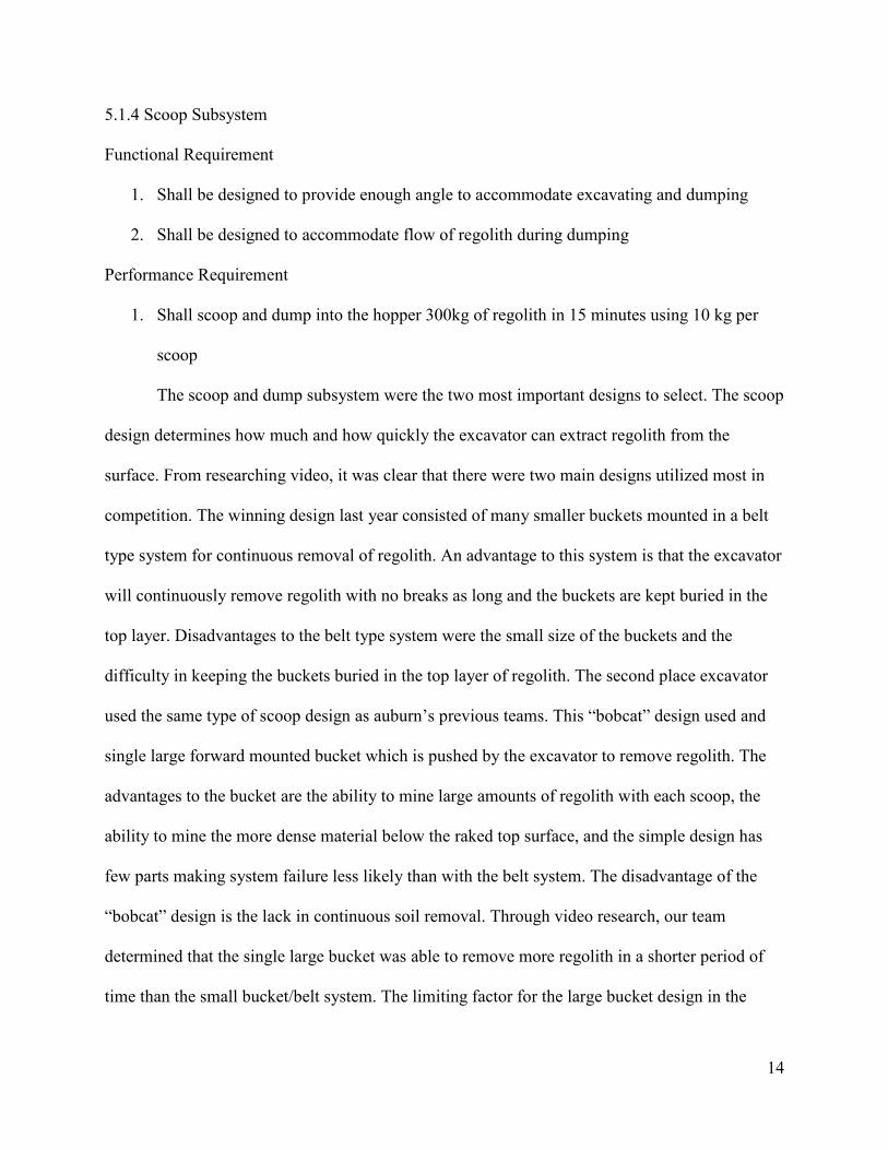
5.1.4 Scoop Subsystem
Functional Requirement
1. Shall be designed to provide enough angle to accommodate excavating and dumping
2. Shall be designed to accommodate flow of regolith during dumping
Performance Requirement
1. Shall scoop and dump into the hopper 300kg of regolith in 15 minutes using 10 kg per
scoop
The scoop and dump subsystem were the two most important designs to select. The scoop
design determines how much and how quickly the excavator can extract regolith from the
surface. From researching video, it was clear that there were two main designs utilized most in
competition. The winning design last year consisted of many smaller buckets mounted in a belt
type system for continuous removal of regolith. An advantage to this system is that the excavator
will continuously remove regolith with no breaks as long and the buckets are kept buried in the
top layer. Disadvantages to the belt type system were the small size of the buckets and the
difficulty in keeping the buckets buried in the top layer of regolith. The second place excavator
used the same type of scoop design as auburn’s previous teams. This “bobcat” design used and
single large forward mounted bucket which is pushed by the excavator to remove regolith. The
advantages to the bucket are the ability to mine large amounts of regolith with each scoop, the
ability to mine the more dense material below the raked top surface, and the simple design has
few parts making system failure less likely than with the belt system. The disadvantage of the
“bobcat” design is the lack in continuous soil removal. Through video research, our team
determined that the single large bucket was able to remove more regolith in a shorter period of
time than the small bucket/belt system. The limiting factor for the large bucket design in the

15
previous competition was the inability to store regolith. The large bucket excavators were forced
to travel to the collection bin after a single scoop was made wasting precious minutes of digging
time. The single large bucket scoop was selected as the design to move forward due to the ability
to mine the most regolith within the shortest period of time. This design also prevents total
mission failure if the dump subsystem fails.
5.1.5 Dump Subsystem
Functional Requirement
1. Shall provide a method of keeping regolith from spilling during transport
2. Shall be designed to accommodate flow of regolith during dumping
Performance Requirement
1. Shall hold maximum 150kg of regolith
The dump subsystem design was met with many different initial ideas. The winning team
from the previous year’s competition used a hopper design paired with a belt/bucket unloader.
The second place team used a completely different design utilizing the scoop/dump system as a
single unit. As stated earlier, the single unit scoop/dump system wasted large amounts of time
maneuvering between the mining area and the collection bin. A large hopper design was chosen
to prevent the need to make so many trips to and from the collection bin. A design for the
mechanism to be used to empty the hopper then had to be chosen. Three main design options
were considered for emptying the hopper: an auger system, a belt system, and the actual hopper
as the dump system. An auger would continuously remove the regolith from the hopper as long
as loose material was entering the auger screw, but the material properties of the regolith cause it
to clump together. One of these clumps could lodge itself over the auger screw entrance

16
preventing the auger from removing any regolith from the hopper. The belt dump system allows
for continuous removal of regolith from the hopper. However, the material entrance is not
required to be enclosed as an auger entrance would be solving the regolith clumping problem.
The final design option was to have the entire hopper be lifted by an actuator and pivot around
the top rear of the excavator. This design was selected due to the ability to dump the entire load
all at once. The chances of system failure are lower than that of the other two subsystems with
the actuator being the only component that could cause the system to fail.
Figure 6 shows the decision matrix used in the analysis and choice of each subsystem
design.
Figure 6 : Decision Matrix

17
5.2 Subsystem Design Engineering:
The final concept chosen is a 6 wheel, scoop bucket, dump hopper design. Figure 7
shows a screen shot from the 3D Solid Edge assembly of the excavator concept.
Figure 7 : 3D Model of Final Concept
The Lunar Excavator project was initially broken into five separate subsystems: electrical
system, drive system, frame system, scoop system, and dump system. Concept of operation,
details of the work done to date for each subsystem, and the test plan to validate and verify the
system are discussed below.
5.2.1 Concept of Operations
The developed lunar excavator must operate precisely in a dusty and dirty environment.
It needs to be able to scoop, transport, and dump as much regolith as it can in 15 minutes. The
concept of operations is meant to show how the excavator will meet the system requirements.
Operations are given in a timeline.
Time-ordered sequence of events:

18
1) Two Netbooks are booted up and the onboard Netbook connects and runs software
automatically
2) The control module is opened on the control Netbook using Python software
3) The router power is connected and both Netbooks are connected to the team’s
network
4) The Xbox 360 controller is connected to the control Netbook
5) The connect button and remote start button are pressed on the control module, which
is on the control Netbook
6) The Xbox 360 controller is used to control the excavator through the following steps
7) Bucket is pushed along surface of regolith until it reaches maximum capacity as
shown in Figure 8
Figure 8 : Excavation Process
8) Bucket is rotated upward so that bucket dumps into large hopper on vehicle as shown
in Figure 9

19
Figure 9 : Filling Storage Hopper
9) When hopper reaches capacity, vehicle is backed up to collection bin
10) Hopper is dumped into collection bin, and vehicle is moved back to digging section
as shown in Figure 10
Figure 10 : Dumping the Hopper
5.2.2 Electrical Subsystem
The electrical system has not been analyzed thoroughly to date due to the lack of
knowledge of needs for the subsystem. An electrical engineering senior design team will be
assigned to the lunar excavator project in the fall semester. The group will help design and build
the electrical system for the lunar excavator. The drive, scoop, and dump systems will all utilize

20
electrical components, so each of these subsystems must be analyzed prior to alteration of the
electrical system. The electrical system from last year’s excavator will be incorporated into this
year’s design. The current electrical diagram is shown in Appendix E. Testing of the old
excavator and electrical system was performed at the National Soil Dynamics Research
Laboratory. The electrical system performance proved satisfactory. The only issues were with
the battery and Netbook housing. Battery connection was lost because of lack of constraint. As
of now the battery and Netbook are just placed in the frame with no constraints. The new design
will incorporate specific housing for each to eliminate this issue and to protect/cushion the
Netbook from vibration damage. The current electrical system is connected to the frame with
Velcro. This electrical system will be taken out of the old excavator and attached to the new
excavator’s frame in the same fashion.
5.2.3 Drive Subsystem
The drive system chosen for the excavator is a six wheel option; each wheel is powered
by a motor, as shown in Figure 11.
Figure 11 : Drive/Frame Subsystem

21
The motor specifications for the current motors are attached in Appendix F. By adding
two more motors and improving the gear ratio, the current motors will be strong enough to move
the lunar excavator at an acceptable speed. Speed data for the current motors with different gear
ratios is given in Table 1.
Table 1- Speed Data
Having a small bucket dumping into a bigger hopper, being able to transport a significant
amount of weight was a concern. Speed tests were performed at the National Soil Dynamics
Research Laboratory using last year’s excavator. Table 2 shows the data that was gathered from
testing.
Table 2 : USDA Speed Testing
Speed Test Results
Weight
Added Distance Time
Avg.
Velocity
0 kg 5 m 7.0 sec 0.714 m/s
95 kg 5 m 8.0 sec 0.625 m/s
196 kg 5 m 10.3 sec 0.485 m/s
The motor’s performance was not affected much by the added weight. The loss of
velocity was due mostly to the fact the test was done with the old excavator which has four small
wheels and minimal ground clearance. So with the six wheels that are bigger in diameter and
wider on the final concept, these test results can be considered worst case scenario. This test
proves that our design should be able to carry the 150 kg max load.
Mass Distance Time velocity Wheel Wheel Rpm Motor Rpm (Geared) Rpm (with no Geared)
(kg) (m) (s) (m/s) (Rps ) (78:1 gear ratio) (26:1 gear ratio) (1:1 gear ratio)0 5 7 0.714 1.007 60.42 181.26 4712
95 5 8 0.625 0.8815 52.89 158.67 4125195 5 10.3 0.485 0.684 41.04 123.12 3201

22
Finite Element Analysis was performed on the wheels that were developed for the lunar
excavator. The analysis was done using SolidEdge software, and a medium-sized tetrahedral
mesh was used. The wheels are made of ultra-high molecular weight polyethylene, for which
SolidEdge contains built-in properties. The wheels have an outer diameter of ten in., and are four
in. thick. For the analysis, the 0.5 in. center cylinder in the wheels was fixed in all directions.
This is the center cylinder that the axle will pass through. 2450 N of force was applied to
approximately fifteen degrees of the wheels directly between two spokes. This corresponds to
about 250 kg resting on 1/24th of the circumference of the wheel. The lunar excavator will weigh
no more than eighty kg, and will be capable of hauling about 150 kg. Therefore the total
maximum weight will be about 230 kg. Under ideal terrain conditions the weight will be
dispersed relatively evenly between six wheels. This means that our analysis is a worst case
scenario in which the excavator is balancing on one wheel with an overflowing hopper. Even
under such unrealistic conditions, the total deflection at the end of the wheel is only 2.25 mm.
The maximum Von Misses stress is about 9.5 MPa, as shown in Figure 12, and the yield strength
of ultra-high molecular weight polyethylene is 19.5 MPa. Therefore the factor of safety for the
wheels is about 2.05.

23
Figure 12 - Wheel FEA

24
5.2.4 Frame Subsystem
The frame of the excavator will be similar to the previous year’s frame design. The
fiberglass square tubing will be used for the frame material. The fiberglass material is lighter
than aluminum, and the material has been proven through testing to be strong enough to handle
the loads exerted on the excavator. A central box of tubing with paneling will be used to house
the electronics. All of the other subsystems will extend from the central box. CAD analysis in
Solid Edge, shown in Appendix G, validates that the frame geometry setup has no conflicts with
the other subsystems as currently designed. The CAD drawing of the Drive/Frame System is
shown in Appendix G.
` Finite Element Analysis was performed on the fiberglass tubing that will be used for the
frame of the lunar excavator. The analysis was done using SolidEdge software, and a medium-
sized tetrahedral mesh was used. The fiberglass tubing has outside dimensions of 1.5 in by 1.5
in., and the tubing is 0.125 in thick. The tubing was ordered from McMaster-Carr and the
specification sheet shown in Appendix F states that the modulus of elasticity ranges from 2.8-5.5
x 106 psi. When the two numbers are averaged, the modulus of elasticity is approximately 4.15 x
106 psi, or 28,613 MPa. A new material was created in SolidEdge using 28,613 MPa as the
modulus of elasticity, and the other material properties were input into SolidEdge using the same
averaging system. After creating the new material, a three point bending test was performed
using a four foot long piece of tubing. The tube was fixed in all directions in the middle of the
tube, and a force of 2000 N was applied to each end in the vertical direction. This test
corresponds to about 204 kg being placed at each end of a very long piece of tubing, which is
beyond the expected load that will be placed on the frame.

25
After performing the test, the maximum deflection at each end was 56.4 mm. The
maximum Von Misses stress occurred on the top and bottom of the tube, above and below the
fixed center point, and was 266.7 MPa, as shown in Figure 13. The top of the tube was in
tension, while the bottom was in compression. This stress and displacement were deemed too
large for a 2000 N force, even though it was applied through a two foot moment arm. To remedy
this problem, a piece of untreated pine wood was created in SolidEdge using the properties found
at matbase.com (Appendix F). A piece of pine wood was created that fits inside the four foot
length of fiberglass tubing. The same position was fixed and the same load was applied at each
end. The maximum deflection at each end was reduced to 8.7 mm, and the maximum Von
Misses stress occurred in the same position, but was reduced to about 4.5 MPa. After studying
this analysis, it was deemed necessary to use pine wood block inserts in areas of the frame that
will be stressed with a large bending force, such as any tube that an actuator will be mounted to.
The yield strength of the fiberglass tubing is reported to be 162 MPa. Therefore, a tube that is not
reinforced with wood would break if placed under the simulated load. However, one reinforced
with wood would not break.

ⅰҘ
26
Figure 13 - 3 pt. bend test without wood
5.2.5 Scoop Subsystem
The scoop system chosen for the excavator utilizes an arm and two actuators to operate a
large bucket as shown in Figure 14.
Figure 14 : Scoop Subsystem

27
This design is similar to the design of the previous year’s excavator. After watching
many competition videos, a conclusion was drawn that the large bucket system could remove the
greatest amount of regolith for a given time period. After calculating the maximum volume of
regolith the bucket could hold and using an average density of one g/cm^3, the maximum weight
the bucket and arm would need to support is eighteen kilograms. Finite element analysis while
applying uniform pressure equal to having a full load proved that the bucket and arm could
handle the maximum stress. The initial design of this system used a motor to rotate the base of
the arm for motion control, but the torque needed to overcome the moment was determined to be
unrealistic by working model analysis. A revised design using an actuator mounted in front of
the arm/frame pivot point applying a linear force to the arm was devised. Also, the excavator
bucket differs from the previous year’s design. The current bucket will be smooth on all interior
surfaces allowing regolith to slide in and out with a minimum dumping angle. To allow the
bucket to gather more regolith with each scoop, the width of the bucket was decreased in
comparison to the previous year’s bucket. This allows the excavator drive system to have enough
power to not bog down while driving the scoop into the regolith.
Bucket analysis of preformed using Solid Edge, Working Model, and manual
calculations. The goal of the analysis was to determine the mass of regolith collected in a single
scoop and analyze the bucket arms if they are strong enough to carry the load. Brackets will be
tested to find the correct number and strength to with stand the force of lifting a full load.
Knowing the density of lunar regolith and the volume of the bucket the total mass of one
scoop can be derived. The volume of the bucket measured 23916 cm3 which when multiplied by
the density of regolith comes out to be approximately 23.9 kg of regolith per scoop. In reality the
bucket cannot be filled completely and the regolith may be less dense than the 1 gm/cm3 so a

28
estimation of 10 to 15 kg per scoop was made. During testing between 10 and 15 kg was used as
the force pressing against the inside of the bucket. Finite element modeling was used to quickly
test various configurations of hinges, arms, and weights.
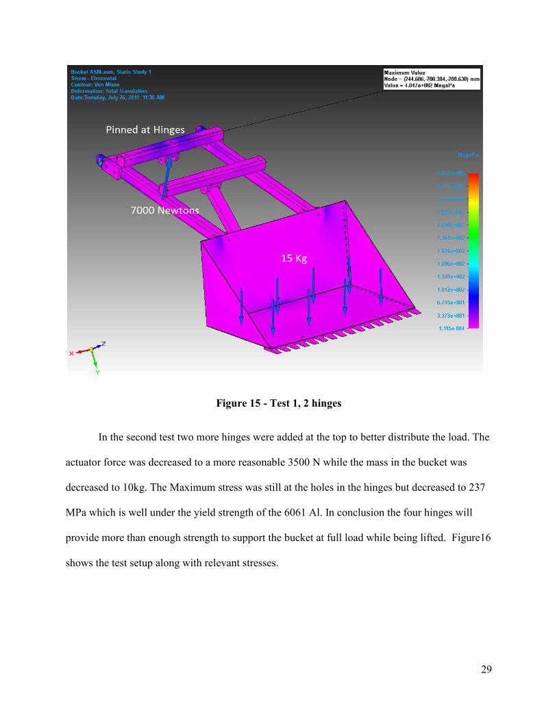
FEM testing was performed using the simulation solver in Solid Edge. In the first test the
bucket was initially pinned at the top 2 hinges with a 15 kg load in the bucket. A force of 7000 N
was applied to the bracket where the actuator will mount. The goal of the test was to estimate
whether the hinges would be strong enough to support the lifting bucket. The analysis showed a
maximum stress of 404.7 MPa which was centered holes in the hinges. The yield strength of the
6061-T6 aluminum is 276 MPa which indicates there will be yielding. Deflection was negligible
during this test. The test results with locations of loading are shown in Figure 15
29
Figure 15 - Test 1, 2 hinges
In the second test two more hinges were added at the top to better distribute the load. The
actuator force was decreased to a more reasonable 3500 N while the mass in the bucket was
decreased to 10kg. The Maximum stress was still at the holes in the hinges but decreased to 237
MPa which is well under the yield strength of the 6061 Al. In conclusion the four hinges will
provide more than enough strength to support the bucket at full load while being lifted. Figure16
shows the test setup along with relevant stresses.

蘐҇
30
Figure 16 - Test 2, 4 hinges
Testing was performed on the mounts that hold the other side of the large bucket actuator. These
mounts are made of one half inch thick 6061 aluminum to ensure zero deflection. The testing set
up is the mounts attached rigidly to the frame with 4500 newtons applied down ward. The results
of the test show a maximum of 170 Mpa which is well below the yield strength of the 6061

ⅰ҅
31
aluminum. Figure 4 shows the locations of the force and the test results.
Figure 17 - Bottom Bracket Test
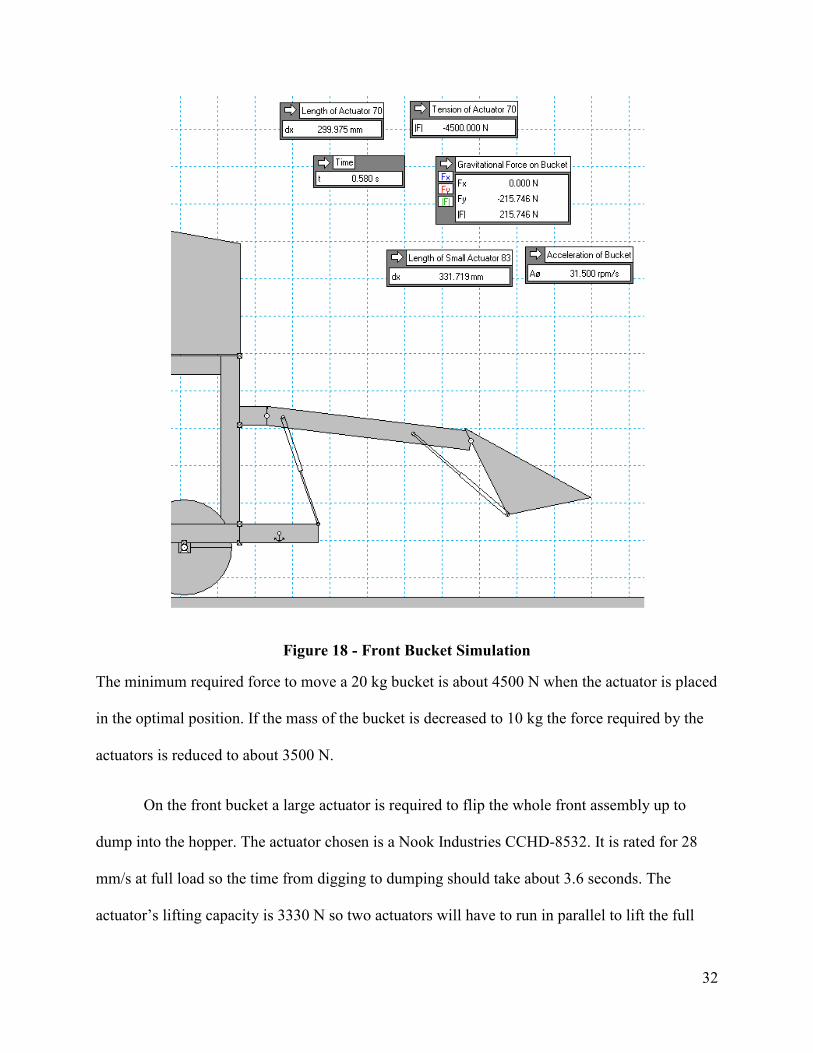
Working Model was used to determine the minimum amount of force required to lift the
bucket at full load. Through trial and error the location along with the strength of the actuators
was found. Each actuator tested had different compressed lengths and strokes, so individual
testing were required for each actuator. Figure 17 shows the final large bucket actuator design
along with forces.
᠐ ҆
32
Figure 18 - Front Bucket Simulation
The minimum required force to move a 20 kg bucket is about 4500 N when the actuator is placed
in the optimal position. If the mass of the bucket is decreased to 10 kg the force required by the
actuators is reduced to about 3500 N.
On the front bucket a large actuator is required to flip the whole front assembly up to
dump into the hopper. The actuator chosen is a Nook Industries CCHD-8532. It is rated for 28
mm/s at full load so the time from digging to dumping should take about 3.6 seconds. The
actuator’s lifting capacity is 3330 N so two actuators will have to run in parallel to lift the full

33
bucket. The locations of the hinges was made as precisely as possible for maximum speed while
staying within the limits of the materials strength. The full spec sheet for the larges actuator is
found in Appendix 1.
The small actuator on the bucket is mainly used to hold the bucket steady and in position
when the digging is occurring. The static load for the small actuator is 4459 N which is more
than enough to hold back the bucket. The dynamic load for tilting the bucket back while
dumping is 2230 N, which is an ample force to flip back the 20 kg bucket. The actuator is rated
for 18 mm/s which will take about 2 seconds to flip the bucket back when dumping. The 2
second time is accounting for the actuator being mounted where the required stroke is only about
1.7 inches. The full spec sheet the small bucket actuator is found in Appendix H.
5.2.6 Dump Subsystem
Finite Element Analysis was performed on the Hopper Subsystem of the lunar excavator
utilizing the simulation solver tool in solid edge. The body of the hopper was constructed using
two millimeter thick sheets of 6061-T6 aluminum. The hopper has six pieces of fiberglass tubing
strategically mounted to the bottom of the main plate for added support. A 3/8” aluminum plate
was placed in position below the bearings mounted to the actuator shaft to dissipate the large
force over a bigger surface area. Finally, aluminum blocks were added beneath the frame
bearings to extend the hopper above the tops of the frame mounts.
To perform the Finite Element Analysis, a force equivalent to 110 kg was applied to the
bottom plate of the hopper and a force equivalent to 40 kg was applied to the main plate. The
maximum weight that the hopper would hold was calculated to be 150 kg of lunar regolith. A
4000 Newton force was also applied to the hopper to simulate the actuator lifting a fully loaded

᠐ ҆
34
hopper. The only motion constraints applied for the analysis were pinning the frame bearings.
This prevented the bearings movement in the three linear degrees of freedom but allowed
rotation.
The simulation yielded a maximum Von Misses stress of 97.5 MPa as shown in Figure 19
and Figure 20. The yield strength of 6061-T6 aluminum is 275.8 MPa providing a factor of
safety of about 2.83. The maximum deflection of the hopper was approximately 2.7 millimeters,
as shown in Figure 21, with the maximum loads applied.
Figure 19: Hopper FEA Bottom View

᠐ ҆
35
Figure 20: Hopper FEA Side/Top View
Figure 21: Hopper FEA Displacement

᠐ ҆
36
On the final design, when the hopper dumps the regolith into the collection bin it hits 45 °
when it reaches the maximum allowable height of 2m. An aluminum angle test was conducted
to find out at which what angle regolith slides off of a piece of aluminum sheet as shown in
Figure 22. Concrete mix, acting as lunar regolith stimulant, was placed onto a piece of
aluminum plate with a protractor used for reading the angle. The plate was slowly lifted, starting
at 0°, until all of the concrete mix slid off of the plate. Numerous tests were conducted. The
lowest angle at which all of the lunar stimulant slid off of the plate was 31° and the highest angle
was 36°. The testing verifies that 45° is a sufficient angle for the hopper to dump the regolith
into the collection bin.
Figure 22: Aluminum Angle Test
5.3 Validate and Verify
Through the entire systems engineering process it is important to make sure that the
system will meet all requirements once completed. A large part of making sure that the design is
on track is validation and verification. Validation for this senior design project will be done
using mostly Portland cement mix to represent lunar regolith. The first test that was conducted
showed the required angle of the hopper in order to dump a load of regolith. A sheet of

᠐ ҆
37
aluminum representing the hopper bottom was laid flat and covered with the Portland cement
and then lifted until all of the cement slides off. The angle of the aluminum was calculated, and
the 55° angle of the hopper was determined sufficient.
An actual size prototype of the lunar excavator was built for the final presentation. The
fiberglass frame for the actual excavator is about 80% complete and was used for the prototype.
The frame was built to CAD drawings out of the fiberglass tubing. The hopper, bucket, and the
wheels were made out of plywood. The main reasons for building a prototype was to get ahead
on building the excavator frame and to verify the Solid Edge assembly. The prototype was
verification that our design will work. It also proved that the excavator has sufficient ground
clearance Figure shows a picture of the finalized prototype.
Figure 23: Prototype

駀Ҏ
38
Also, CAD drawings and finite element analysis verified correct operation of the design.
Verification of Auburn’s old lunar excavator was done at the National Soil Dynamics Research
Laboratory, since most of the electronics from the old excavator will be used in the new
excavator. Results from the test showed some flaws in the old design, but also proved that the
current electric motors are sufficient for use on the new excavator. Testing was done of
acceleration using various loads. With no external load on the old excavator it was able to travel
five meters in 7.0 seconds. Under an external load of ninety-five kilograms the old excavator
was able to travel five meters in 8.0 seconds. Under an external load of 196 kilograms the old
excavator was able to travel five meters in 10.3 seconds. This was deemed an acceptable
acceleration if at least 300 kilograms of regolith is to be gathered in fifteen minutes.
All subsystems will be operated independently, or verified, before being integrated into
the total system. This will ensure that all components will work as specified. The first half of
fall will consist of building the excavator and the second half will consists of numerous testing of
the subsystems and system. All subsystems will be operated independently, or verified, before
being integrated into the total system. This will ensure that all components will work as
specified.
6.0 Interfaces
Mechanical interfaces of the bucket, arm, and hopper subassemblies to the frame and also
actuator interfaces are all supported by pin joints. The electrical to mechanical interfaces will
utilize the same Sabertooth Motor Controllers as the previous year’s excavator. Further interface
details will be discussed in the critical design report.

侠Ґ
39
7.0 CDR Economic Analysis
Figure 1 shows the critical design review bill of materials. Quotes were obtained for the
majority of the items in the breakdown. For the items that will be reused from last year’s
excavator, prices were taken from the previous year’s bill of material list. Total estimated costs
for parts that will be reused in the design were set to $0.00. The total estimated cost at this point
in the design process is $3,668.53. This price assumes the old batteries, motors, and hopper
actuator will be reused. At this point, the budget is unknown. If the budget ends up being
$5000.00 there will be room to increase speed and power. Next semester, a finalized cost
breakdown will be created after all of the materials for the excavator are purchased.

侠Ґ
40
Table 3: CDR Economic Analysis
CDR Economic Analysis
Item Description Supplier
Supplier
Part #
Lead
Time
Original
Unit
Cost Qty
Total
Estimated
Cost
1 6061 Aluminum 36"x48" sheet, 0.08" thick
Metals by the Inch
2-3 days $79.17 4 $316.68
2 2x6x8' Untreated Pine Wood Home Depot 1 day $2.40 1 $2.40
3
Bucket Tilt Actuator Moteck ID10-12-20-A-100 2 weeks $108.00 1 $108.00
4
Bucket Lift Actuator Nook Ind. CC-18 3-4 weeks $600.00 2 $1,200.00
Hopper Actuator (reuse) - 1 $0.00
5 Fiberglass Tubing 1-1/2" x 1-1/2" 10' Section McMaster-Carr 8548K32 1 day $63.41 3 $190.23
6 UHMW Polyethylene 10" Diameter 4" Cut to Length Eplastics
3-5 days $167.46 6 $1,004.76
7 Motor ? ? 6 $0.00
8 Electrical Circuit System (reuse)
Sparkfun Electronics - $70.00 1 $0.00
9 Batteries (reuse) 10 Ah, 24V $130.00 2 $0.00
10 Netbook (reuse)
Netbook Samsung NF310-A01 - $400.00 1 $0.00
11 Cameras (reuse) Newegg.com/ - $40.00 3 $0.00
12 Fasteners McMaster-Carr 1558A21 1 day $100.00 1 $100.00
13 Router (reuse) Newegg.com/ ASUS Router $65.00 1 $0.00
14 Axle McMaster-Carr 8974K113 1 day $12.82 3 $38.46
15
Sabertooth Motor Controllers Trossen Robotics 126233 $125.00 2 $250.00
16
Extra Electrical Components
Sparkfun Electronics $50.00 1 $50.00
17
94 lb Portland Concrete Mix Home Depot 1 day $9.85 20 $197.00
18
Report Copies for all 4 Presentations Copy Cat $100.00 1 $100.00
19 Plywood for Mock up Home Depot 1 day $11.00 1 $11.00
20 Tools for DML Sparkfun Electronics $100.00 1 $100.00
TOTAL ESTIMATED COST $3,668.53

41
8.0 Mass Budget Tracking
Tracking resource budgets is necessary for this project to ensure the weight limitation of
80 kg is met. A rough estimate of the system mass breakdown is shown in Appendix J. The
estimated weight at this point in the design process is 73.4 kg. This mass budget is only an
estimate and will be detailed more accurately in the critical design review that follows further in
the design process.
9.0 Conclusions
For designing the excavator, the mission objective of the NASA’s competition is
collecting 10kg of regolith in 15 minutes. To win the competition, the team made the goal to
collect 500 kg of regolith in 15 minutes. Before selecting the final design, the team had 3
alternative systems (bucket, 6 wheels, and auger), (bucket, 6 wheels, hopper), and (belt with
small buckets, 6 wheels, hopper). To select the final design, the team evaluated the ideas and
picked the best designs, and got the best scores for the bucket, 6 wheels, and hopper system. The
design needed to be simple and have less complicated components to avoid braking. The
excavator mass requirement is less than 80kg so to make the excavator light the team selected
fiberglass for the material. Fiberglass is hard enough to handle 200kg of the regolith to carry.
For the next review, the team will complete the set of dimensioned part and assembly
drawings, of details with the solid edge program, so that team could build the device from the
drawing set.

侠Ґ
Appendix A: 2011 Lunabotics Mining Competition Rules and Rubrics2011 Lunabotics Mining Competition Rules and Rubrics
42

뾰ҁ
43

44

45

뾰ҁ
46

뾰ҁ
47

뾰ҁ
48

ⅰ҆
49
Appendix E: Electrical Diagram

ⅰ҆
Appendix F: Wheel Motor Specification Sheet: Wheel Motor Specification Sheet
50

뾰ҁ
51

52

Appendix G: Solid Edge
Appendix G.1:Solid Edge Finite AnalysisAppendix G.1:Solid Edge Finite Analysis
Hopper Bending Displacement
Hopper Von Mises
53

Bucket Von Mises Stress
Bucket Bending Displacement
54

55
Appendix G.2: CAD Drawings
Drive System/Frame CAD Drawing

ⅰ҈
56
Scoop System CAD Drawing

57
Appendix H: Working Model Analysis
Full Excavator
Front Actuator Fully Extended

戀҇
58
Front Arm Actuator Extended
Full Range on Hopper Actuator

ⅰҗ
59
Hopper Actuator Extending