measuring software functional size from business …
TRANSCRIPT
July 20, 2011 14:41 WSPC/117-IJSEKE - SPI-J111 0218-1940S0218194011005359
International Journal of Software Engineeringand Knowledge EngineeringVol. 21, No. 3 (2011) 311–338c© World Scientific Publishing CompanyDOI: 10.1142/S0218194011005359
MEASURING SOFTWARE FUNCTIONAL SIZEFROM BUSINESS PROCESS MODELS
CARLOS MONSALVE∗,†,‡, ALAIN ABRAN†,§ and ALAIN APRIL†,¶
∗CIDIS-FIEC, Escuela Superior Politecnica del LitoralKm. 30.5 via Perimetral, Guayaquil, Guayas, Ecuador
†Software Engineering Research Laboratory, Ecole de Technologie Superieure1100 rue Notre-Dame Ouest, Montreal, Quebec H3C 1K3, Canada
‡[email protected]§[email protected]¶alain.april @etsmtl.ca
ISO 14143-1 specifies that a functional size measurement (FSM) method must providemeasurement procedures to quantify the functional user requirements (FURs) of soft-ware. Such quantitative information, functional size, is typically used, for instance, insoftware estimation. One of the international standards for FSM is the COSMIC FSMmethod — ISO 19761 — which was designed to be applied both to the business applica-tion (BA) software domain and to the real-time software domain. A recurrent problemin FSM is the availability and quality of the inputs required for measurement purposes;that is, well documented FURs. Business process (BP) models, as they are commonlyused to gather requirements from the early stages of a project, could be a valuable sourceof information for FSM. In a previous article, the feasibility of such an approach for theBA domain was analyzed using the Qualigram BP modeling notation. This paper com-plements that work by: (1) analyzing the use of BPMN for FSM in the BA domain;(2) presenting notation-independent guidelines for the BA domain; and (3) analyzingthe possibility of using BP models to perform FSM in the real-time domain. The mea-surement results obtained from BP models are compared with those of previous FSMcase studies.
Keywords: Functional size measurement; FSM; COSMIC; ISO 19761; business processmodel; business process modeling; Qualigram; BPMN; requirements modeling.
1. Introduction
The functional size of software is an important input for planning, buying, devel-oping, improving, and maintaining software systems [1]. In particular, it providesvaluable information for estimating the effort required to develop the measured soft-ware. Based on that estimation, software managers can successfully plan resourcesand estimate costs for the software project [2]. Functional size measurement (FSM)can be performed a priori (i.e. based on the project specifications) or a posteriori(i.e. based on the finished software product). The former is desirable for planning a
311

July 20, 2011 14:41 WSPC/117-IJSEKE - SPI-J111 0218-1940S0218194011005359
312 C. Monsalve, A. Abran & A. April
software project and the latter for productivity analysis and benchmarking pur-poses. For estimation, the measurement of functional size should be performedduring the early stages of the project.
Several methods have been proposed for FSM, one of which is the COSMIC FSMmethod [3]. COSMIC was designed to be applied in various functional domains:(1) business application software; (2) real-time software; and (3) a combination ofthe two. It is completely open and available in multiple languages, and it has beenreported to be easy to learn and use [3]. Since 2003, COSMIC has been accepted asan international standard, ISO/IEC 19761:2003 “Software engineering — COSMIC-FFP — A functional size measurement method” [4]. The COSMIC measurementunit is a COSMIC function point (CFP), which represents one “data movement”[3], and the functional size of software is obtained by adding the data movementsidentified.
Business process (BP) models are designed to be useful for documenting, com-municating, and improving organizational business processes. They are also used bysoftware engineers and business analysts to gather the software and system require-ments from the early stages of the development process [5–8]. A BP model maytherefore be a valuable source of information for FSM.
It was not until recently that the use of BP models for COSMIC FSM has beenstudied [9, 10]. This article complements the results given in [9] by identifying thecandidate rules for mapping the various COSMIC concepts to the Business Processmodel and Notation (BPMN) [11] constructs. Considering that COSMIC allows thefunctional size of real-time software to be measured, this article also analyzes thepossibility of modeling real-time software using BP models to measure its functionalsize. The candidate mapping rules and modeling rules to be taken into considerationfor FSM purposes are identified for both the business application software domainand the real-time software domain. To verify the value of the proposed approaches,this article compares the results obtained with those of previous FSM case studies.Finally, this article also compares the results obtained with those from [9] to elabo-rate a set of general guidelines for modeling BPs for FSM purposes in the businessapplication domain. These guidelines are independent of the modeling notation.
The structure of this paper is as follows. Section 2 reviews related works. Sec-tion 3 introduces the BP modeling notations that are explored in this research.Section 4 describes the methodology used in this research. Sections 5 and 6 presentthe use of a BP model for FSM in the business application domain and in the real-time domain respectively. Section 7 discusses the results obtained. Finally, Sec. 8concludes the paper with a review of the contributions of this research, its limita-tions, and future work.
2. Related Works
Two of the research works related to the feasibility of using a BP model for FSM thatcould be identified before the publication date of [9] do not make use of COSMIC

July 20, 2011 14:41 WSPC/117-IJSEKE - SPI-J111 0218-1940S0218194011005359
Measuring Software Functional Size from Business Process Models 313
as the proposed FSM method. The first work identified [12] is based on the use ofthe IFPUG Function Point Analysis (FPA) method, release 4.0 [13]. It proposedan approach for measuring reuse “in the requirements conceptualization phase” ofan enterprise resource planning (ERP) software project. To achieve its goal, theapproach proposed to map the various modeling concepts of a commercial ERPsoftware development tool to the “base logical components” of the IFPUG FPAmethod. The FSM method was used to measure “the size of the reusable require-ments and the size of the total requirements” as indirect measurements of require-ments reuse in an ERP “implementation project”. The development tool used theEvent-driven Process Chain (EPC) [14] diagrams to represent business requirementsas BP models. Therefore, the mapping rules included the mapping of various EPCmodeling concepts to the “base logical components” of the IFPUG FPA method.The second work [15] used an extension of the EPC to model a military application.In this case, the EPC diagrams were used as part of the requirements elicitationmethodology, but without the need to map the EPC modeling constructs to theconcepts of an FSM method.
The use of conceptual models for FSM with the COSMIC method has beenstudied and analyzed in the research literature, and a complete survey of relatedworks, including its own, is offered in [16]. Following publication of that survey,Lavazza and Bianco [17] studied the use of Unified Modeling Language (UML)[18] diagrams (use case, component, and sequence diagrams) for modeling real-time software to be measured using the COSMIC FSM method. In other work [19],the potential relationships between the measurements obtained from UML use casediagrams and those obtained from other UML diagrams were studied. From all theseworks, only one [20] has included the use of some kind of BP model. The annotatedwork proposed the use of UML activity diagrams as one of the possible optionsfor representing the behavioral aspects of the software being modeled; however, itdoes not provide a rule for mapping between the BP modeling constructs and theCOSMIC concepts. Moreover, the emphasis of this latter work is not related to thefeasibility of using only BP models for FSM.
A more recent work [9] analyzed the feasibility of using a BP model devel-oped in Qualigram [21] for FSM in the business application domain. Qualigram is amanagement-oriented BP modeling notation based on the results of an internationalresearch project [22, 23]. More details of this notation are provided in section 3. Tenmodeling rules for FSM purposes were derived, as well as the necessary rules formapping the various COSMIC concepts to the corresponding Qualigram modelingconstructs. Based on the former rules, the specifications of the February 23, 2008,version of the C-Registration System case study [24] were modeled. The mappingrules were applied in the BP models to identify the data movements, and the mea-surement results were obtained by adding those data movements (see Table 1).Finally, the measurement results were compared with those obtained in the casestudy.

July 20, 2011 14:41 WSPC/117-IJSEKE - SPI-J111 0218-1940S0218194011005359
314 C. Monsalve, A. Abran & A. April
Table 1. Measurement results based on Qualigram: Business appli-cation domain — The C-Registration System case study [24].
Data movements
Procedures E X R W CFP
Login 1 2 1 4Add Professor 1 2 1 1 5Modify Professor 2 2 1 1 6Delete Professor 3 3 1 1 8Select Courses to Teach 4 6 10Add Student 1 1 1 1 4Modify Student 2 2 1 1 6Delete Student 3 3 1 1 8Create Schedule 4 5 2 1 12Modify Schedule 4 6 3 1 14Delete Schedule 3 4 2 1 10Close Registration 3 5 2 1 11Submit Grades 4 4 2 1 11View Report Card 1 2 2 5Total 36 47 20 11 114
3. Why Test the Proposed Approach with Two BP ModelingNotations?
Two factors that are key to the successful modeling of business processes are:(1) the use of an appropriate BP modeling notation [25]; and (2) the active par-ticipation of all the stakeholders, along with a shared vision of business processes[8, 26]. Unfortunately, the evidence shows that business processes are not consis-tently documented [27], and that management and IT stakeholders tend to usedifferent notations, conventions, and techniques to represent them [26]. Conse-quently, various notations for modeling business processes have been developedover the last 20 years, most of them responding to an IT-oriented perspective ofBP modeling.
For this paper, two BP modeling notations have been selected: (1) the BusinessProcess Model and Notation (BPMN), because of its popularity and because of theconsiderable effort under way to establish it as a BP modeling standard [11, 28,29]; and (2) the Qualigram modeling notation [21], because it is a management-oriented BP modeling notation that incorporates different levels of abstraction, andis based on the results of an extensive international research project. With thisselection, it is possible to test the proposed approach using both an IT-oriented BPmodeling notation and a management-oriented BP modeling notation. Moreover,the comparative analysis of the results obtained with both BP modeling notationsleads to the proposal of a set of notation-independent BP modeling rules for FSMpurposes. Section 3.1 presents a short introduction to BPMN, and Sec. 3.2 describesthe Qualigram modeling notation in more detail.
July 20, 2011 14:41 WSPC/117-IJSEKE - SPI-J111 0218-1940S0218194011005359
Measuring Software Functional Size from Business Process Models 315
3.1. Business Process Model and Notation (BPMN)
BPMN is currently an Object Management Group (OMG) standard [11]. It wasinitially developed by the Business Process Management Initiative (BPMI), andin 2004 the BPMN 1.0 specification was released [29]. Later, in 2005, there was amerger between BPMI and OMG, BPMN having been adopted by the latter.
BPMN was created with the idea of providing a unified notation, both for ITand for management stakeholders, that is easy to understand, but at the same timehaving a formal basis [28–31]. For this purpose, the standard includes a basic set ofconstructs called the “Business Process Diagram (BPD) Core Element Set” (CoreSet), and a more complete set, “BPD Extended Set” (Extended Set). The firstset is intended for documentation and communication purposes, and the secondset for developing more detailed models that are appropriate for the analysis andautomation of business processes. According to [27] and [31], the adoption rate ofBPMN is increasing in industry.
BPMN is a modeling notation rich in modeling constructs for representing var-ious types of control flow and events. As a result, BPMN has a high degree ofexpressiveness, but at the same time is highly complex [32]. According to a recentstudy [33] based on the analysis of 120 BP models, of the 50 modeling constructsoffered by BPMN, a typical BP model uses only 9. Those 9 constructs may varyfrom BP model to BP model in an arbitrary way. However, only 4 modeling con-structs were always used by the 120 BP models, and some of the BPMN modelingconstructs were never used.
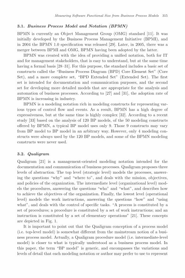
3.2. Qualigram
Qualigram [21] is a management-oriented modeling notation intended for thedocumentation and communication of business processes. Qualigram proposes threelevels of abstraction. The top level (strategic level) models the processes, answer-ing the questions “why” and “where to”, and deals with the mission, objectives,and policies of the organization. The intermediate level (organizational level) mod-els the procedures, answering the questions “who” and “what”, and describes howto achieve the objectives of the organization. Finally, the lowest level (operationallevel) models the work instructions, answering the questions “how” and “usingwhat”, and deals with the control of specific tasks. “A process is constituted by aset of procedures; a procedure is constituted by a set of work instructions; and aninstruction is constituted by a set of elementary operations” [21]. These conceptsare depicted in Fig. 1.
It is important to point out that the Qualigram conception of a process model(i.e. top-level model) is somewhat different from the mainstream notion of a busi-ness process model. Actually, a Qualigram procedure model (i.e. intermediate-levelmodel) is closer to what is typically understood as a business process model. Inthis paper, the term “BP model” is generic, and encompasses the variations andlevels of detail that each modeling notation or author may prefer to use to represent

July 20, 2011 14:41 WSPC/117-IJSEKE - SPI-J111 0218-1940S0218194011005359
316 C. Monsalve, A. Abran & A. April
Fig. 1. Qualigram pyramid, adapted from [21].
an organization’s process. The reader should not infer, therefore, that a Qualigramprocess model has exactly the same general scope as a BP model. Moreover, becausethis paper uses the term “BP model” generically, both Qualigram process modelsand Qualigram procedure models are considered as BP models with different levelsof abstraction.
Another characteristic of Qualigram is its simplicity. The modeling constructs foreach level are based on a set of four basic concepts, along with their correspondinggraphical forms: (1) action; (2) entity; (3) tool; and (4) information [21]. Variationsof the action form are used to represent processes, procedures, work instructions,and elementary operations. Variations of the entity form are used to represent roles(internal and external), units, and external entities. The tool form is used to rep-resent any kind of physical tool or equipment, as well as any kind of documentproduced or used by an action. The information form is used to represent the inputand output flows of information between the various elements modeled. Qualigramclaims that its simplicity makes its notation clear enough to be understood by anytype of stakeholder of the organization. These concepts are depicted in Fig. 2.
Fig. 2. Basic graphical forms of the Qualigram notation, adapted from [21].

July 20, 2011 14:41 WSPC/117-IJSEKE - SPI-J111 0218-1940S0218194011005359
Measuring Software Functional Size from Business Process Models 317
4. Methodology
The methodology used in this research is twofold: (1) The steps to be followed forthe business application software domain, as explained in Sec. 4.1; (2) The steps tobe followed for the real-time software domain, as explained in Sec. 4.2.
4.1. Business application domain
Figure 3 depicts the methodology for the business application software domain.The same methodology is followed for each of the selected BP modeling notations.To test the feasibility of the proposed approach, the version of the C-RegistrationSystem case study dated February 23, 2008, and published by the COSMIC Groupis used [24]. Based on the definitions of the various modeling constructs offeredby the modeling notation, and the definitions of the various COSMIC concepts, amapping table of the COSMIC concepts and the modeling constructs is generated.Also, as a result of the comparison, a set of specific modeling rules is identified toallow the BP models to be used for FSM. The C-Registration System is modeledfollowing these modeling rules. The mapping rules and the BP models are usedto measure the functional size of the system. Finally, the measurement results arecompared with those presented in the C-Registration System case study.
In addition, the results obtained using each of the BP modeling notations areanalytically compared, in order to generate a set of notation-independent BP mod-eling guidelines for FSM purposes.
Fig. 3. Methodology for the business application software domain.
July 20, 2011 14:41 WSPC/117-IJSEKE - SPI-J111 0218-1940S0218194011005359
318 C. Monsalve, A. Abran & A. April
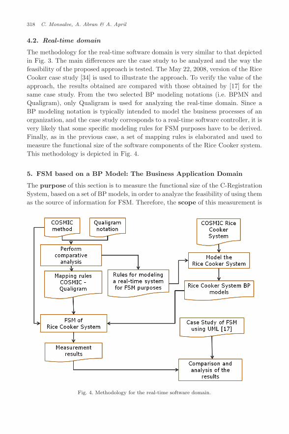
4.2. Real-time domain
The methodology for the real-time software domain is very similar to that depictedin Fig. 3. The main differences are the case study to be analyzed and the way thefeasibility of the proposed approach is tested. The May 22, 2008, version of the RiceCooker case study [34] is used to illustrate the approach. To verify the value of theapproach, the results obtained are compared with those obtained by [17] for thesame case study. From the two selected BP modeling notations (i.e. BPMN andQualigram), only Qualigram is used for analyzing the real-time domain. Since aBP modeling notation is typically intended to model the business processes of anorganization, and the case study corresponds to a real-time software controller, it isvery likely that some specific modeling rules for FSM purposes have to be derived.Finally, as in the previous case, a set of mapping rules is elaborated and used tomeasure the functional size of the software components of the Rice Cooker system.This methodology is depicted in Fig. 4.
5. FSM based on a BP Model: The Business Application Domain
The purpose of this section is to measure the functional size of the C-RegistrationSystem, based on a set of BP models, in order to analyze the feasibility of using themas the source of information for FSM. Therefore, the scope of this measurement is
Fig. 4. Methodology for the real-time software domain.
July 20, 2011 14:41 WSPC/117-IJSEKE - SPI-J111 0218-1940S0218194011005359
Measuring Software Functional Size from Business Process Models 319
given by all the functional user requirements (FURs) of the C-Registration System,as described in [24]. The C-Registration System is business application software thatbelongs to the “application layer” of the “typical layered software architecture” [3].
Two BP modeling notations are used: Qualigram and BPMN. In the next sub-section, the results of using the Qualigram models that were obtained in [9] forFSM purposes are summarized, including the determination that the appropriateQualigram level of abstraction is in agreement with the level of granularity expectedby the COSMIC FSM method. In Sec. 5.2, the specific modeling rules for produc-ing BPMN models suitable for use for FSM are identified. In Sec. 5.3, the rulesfor mapping between COSMIC and BPMN are defined to ultimately measure thefunctional size of the C-Registration System. Finally, in Sec. 5.4, a comparativeanalysis of the results obtained with Qualigram and BPMN is performed in orderto derive a set of notation-independent BP modeling guidelines for FSM purposes.
5.1. Results obtained with Qualigram
This subsection is entirely based on the results obtained in [9]. Ten modeling rulesfor producing Qualigram models suitable to be used for FSM were identified, the firstfour to be applied at the top level of abstraction (i.e. the strategic level) and the lastsix at the intermediate level of abstraction (i.e. the organizational level). Accordingto COSMIC, the recommended level of granularity of the FURs is achievedwhen the functional users: (1) are individuals; and (2) “detect single occurrences ofevents”. According to [9], these conditions seem to be satisfied with the intermediatelevel of Qualigram (i.e. the organizational level).
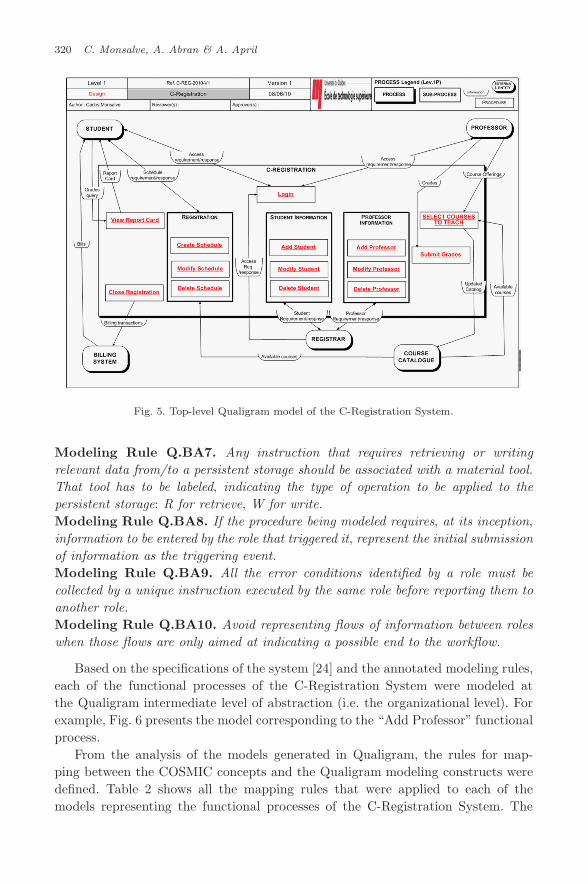
Modeling Rule Q.BA1. At the top level of abstraction (i.e. the strategic level ),represent the software to be measured as a process.Modeling Rule Q.BA2. Following COSMIC principles, consider any exter-nal software component that interacts with the measured software as an externalentity.Modeling Rule Q.BA3. Consider any logical instruction set that is worth detail-ing in more depth as a procedure.Modeling Rule Q.BA4. Represent any user of the software who allows rep-resentation of the inputs and outputs of the procedures modeled as an externalentity.
Based on these four modeling rules, the C-Registration System was representedwith a top-level Qualigram model (i.e. a strategic level model), as depicted in Fig. 5.
Modeling Rule Q.BA5. At the intermediate level of abstraction (i.e. the organi-zational level ), represent the software being measured as an internal role.Modeling Rule Q.BA6. At the intermediate level of abstraction (i.e. the organiza-tional level ), represent any peer software component that interacts with the softwarebeing measured as an external role.
July 20, 2011 14:41 WSPC/117-IJSEKE - SPI-J111 0218-1940S0218194011005359
320 C. Monsalve, A. Abran & A. April
Fig. 5. Top-level Qualigram model of the C-Registration System.
Modeling Rule Q.BA7. Any instruction that requires retrieving or writingrelevant data from/to a persistent storage should be associated with a material tool.That tool has to be labeled, indicating the type of operation to be applied to thepersistent storage: R for retrieve, W for write.Modeling Rule Q.BA8. If the procedure being modeled requires, at its inception,
information to be entered by the role that triggered it, represent the initial submissionof information as the triggering event.Modeling Rule Q.BA9. All the error conditions identified by a role must becollected by a unique instruction executed by the same role before reporting them toanother role.Modeling Rule Q.BA10. Avoid representing flows of information between roleswhen those flows are only aimed at indicating a possible end to the workflow.
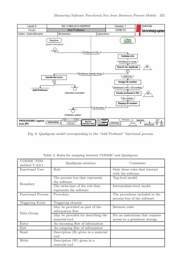
Based on the specifications of the system [24] and the annotated modeling rules,each of the functional processes of the C-Registration System were modeled atthe Qualigram intermediate level of abstraction (i.e. the organizational level). Forexample, Fig. 6 presents the model corresponding to the “Add Professor” functionalprocess.
From the analysis of the models generated in Qualigram, the rules for map-ping between the COSMIC concepts and the Qualigram modeling constructs weredefined. Table 2 shows all the mapping rules that were applied to each of themodels representing the functional processes of the C-Registration System. The
July 20, 2011 14:41 WSPC/117-IJSEKE - SPI-J111 0218-1940S0218194011005359
Measuring Software Functional Size from Business Process Models 321
Fig. 6. Qualigram model corresponding to the “Add Professor” functional process.
Table 2. Rules for mapping between COSMIC and Qualigram.
COSMIC FSMmethod V.3.0.1
Qualigram notation Comments
Functional User Role Only those roles that interactwith the software
Boundary
The process box that representsthe software
Top-level model
The swim-lane of the role thatrepresents the software
Intermediate-level model
Functional Process Procedure The procedures included in theprocess box of the software
Triggering Event Triggering element
Data Group
May be provided as part of theinformation flow
Between roles
May be provided for describing thematerial tool
For an instruction that requiresaccess to a persistent storage
Entry An incoming flow of information
Exit An outgoing flow of information
Read Description (R) given in a materialtool
Write Description (W) given in a
material tool
July 20, 2011 14:41 WSPC/117-IJSEKE - SPI-J111 0218-1940S0218194011005359
322 C. Monsalve, A. Abran & A. April
measurement results were obtained next, by simply adding the various data move-ments (Entries (E), Exits (X), Writes (W), and Reads (R)) that appeared in themodels.
Table 1 shows the measurement results obtained in [9]. Finally, the measurementresults were compared with those obtained in the case study [24]. The COSMIC casestudy presents two sets of results: “step 1” and “step 2”. The first set is obtainedafter applying the COSMIC FSM method to the FURs “exactly as they are written”in the original specifications of the C-Registration System. The second set resultsfrom modifying the FURs in step 1 “by a further assumption”. This paper has onlyconsidered the FURs as given in step 1 of the case study. The comparison of theresults is presented in Sec. 5.3.
5.2. Modeling rules for BPMN
This section uses BPMN version 1.2 (BPMN 1.2) [11] for modeling the specificationsof the C-Registration System and for deriving the modeling rules for FSM purposes.There is a version 2.0 of BPMN (BPMN 2.0) [35], but it is still considered as a Beta2 version at the time of writing this paper. When the term BPMN is used in thispaper without any reference to either of the two versions, it has to be understoodthat, for understanding the authors’ argument, the BPMN version does not affectthe meaning of their assertion.
BPMN does not offer the possibility of representing the C-Registration Systemby a model with similar characteristics to the one depicted in Fig. 5. In BPMN,it is always necessary to represent the workflow of the business process; i.e. eachbusiness process has at least one clear start event that triggers the first activity(task or sub-process), after which a finite set of activities is executed following apredetermined flow that finishes at a clear end event [11]. A business process mayhave multiple end events. In BPMN 1.2, a BP should be contained in a pool, and,even if it is not drawn, it is “implied by default” [36]. A BP can interact with anyexternal participant (customer, provider, external actor, other BP) through sendingand receiving messages [11]. In these cases, the external participant is considered asan external BP and may be represented as a pool in the BPMN diagram. In orderto differentiate between the pool of the BP and the pool of any external participant,this research will refer to them as “main pool” and “secondary pool” respectively.A pool may be partitioned into lanes, which are used to represent any organizationor categorization of activities [11]. Typically, lanes are used to represent “performerroles or organizational units” [36].
Modeling Rule BPMN1. Consider any logical instruction set that is worth detail-ing as a separate BP.Modeling Rule BPMN2. Represent the software to be measured as a lane in themain pool.Modeling Rule BPMN3. Represent any external software component that inter-acts with the measured software as a secondary pool.
July 20, 2011 14:41 WSPC/117-IJSEKE - SPI-J111 0218-1940S0218194011005359
Measuring Software Functional Size from Business Process Models 323
Modeling Rule BPMN4. Represent any user of the software as a secondary pool(external user) or as a lane in the main pool (internal user).Modeling Rule BPMN5. All the error conditions identified within the lane thatrepresents the software to be measured must be collected by a unique event or aunique activity before reporting them to another lane or pool.
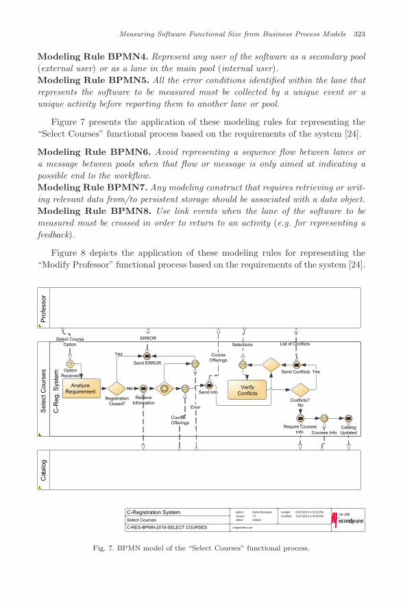
Figure 7 presents the application of these modeling rules for representing the“Select Courses” functional process based on the requirements of the system [24].
Modeling Rule BPMN6. Avoid representing a sequence flow between lanes ora message between pools when that flow or message is only aimed at indicating apossible end to the workflow.Modeling Rule BPMN7. Any modeling construct that requires retrieving or writ-ing relevant data from/to persistent storage should be associated with a data object.Modeling Rule BPMN8. Use link events when the lane of the software to bemeasured must be crossed in order to return to an activity (e.g. for representing afeedback).
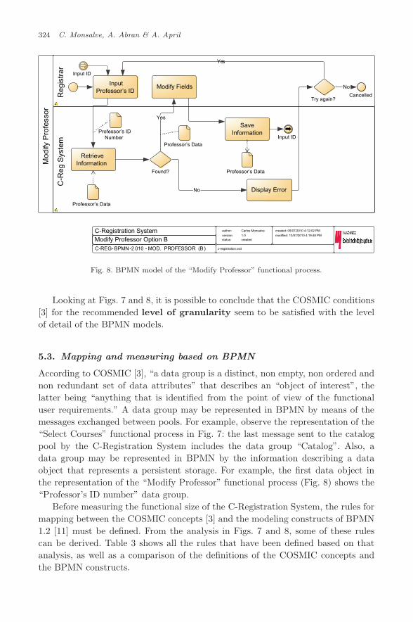
Figure 8 depicts the application of these modeling rules for representing the“Modify Professor” functional process based on the requirements of the system [24].
C-REG-BPMN-2010-SELECT COURSES
C-Registration SystemSelect Courses
author:
version:status:
Carlos Monsalve
1.0created
created:
modified:
05/07/2010 4:12:02 PM
13/07/2010 4:19:48 PM
c-registration.vsd
Pro
fess
orS
elec
t Cou
rses
Cat
alog
Select CourseOption
AnalyzeRequirement
RegistrationClosed?
Yes
No
Send ERROR
ERROR
RetrieveInformation
CourseOfferings
Error
Send Info
CourseOfferings
VerifyConflicts
List of Conflicts
Require CoursesInfo Courses Info
CatalogUpdated
Send ConflictsOptionReceived
C-R
eg. S
yste
m
Selections
Yes
Conflicts?No
Fig. 7. BPMN model of the “Select Courses” functional process.
July 20, 2011 14:41 WSPC/117-IJSEKE - SPI-J111 0218-1940S0218194011005359
324 C. Monsalve, A. Abran & A. April
MOD. PROFESSOR (B )C-REG- BPMN-2 010 -
C-Registration System author:
version:status:
Carlos Monsalve
1.0created
created: 05/07/2010 4:12:02 PM
modified: 13/07/2010 4:19:48 PM
c-registration.vsd
Mod
ify P
rofe
ssor
Reg
istr
arC
-Reg
Sys
tem
RetrieveInformation
Found?
Yes
Display Error
Professor’s Data
Modify Fields
Professor’s Data
InputProfessor’s ID
No
SaveInformation
Professor’s Data
Try again?
Yes
Cancelled
No
Professor’s IDNumber
Modify Professor Option B
Input ID
Input ID
Fig. 8. BPMN model of the “Modify Professor” functional process.
Looking at Figs. 7 and 8, it is possible to conclude that the COSMIC conditions[3] for the recommended level of granularity seem to be satisfied with the levelof detail of the BPMN models.
5.3. Mapping and measuring based on BPMN
According to COSMIC [3], “a data group is a distinct, non empty, non ordered andnon redundant set of data attributes” that describes an “object of interest”, thelatter being “anything that is identified from the point of view of the functionaluser requirements.” A data group may be represented in BPMN by means of themessages exchanged between pools. For example, observe the representation of the“Select Courses” functional process in Fig. 7: the last message sent to the catalogpool by the C-Registration System includes the data group “Catalog”. Also, adata group may be represented in BPMN by the information describing a dataobject that represents a persistent storage. For example, the first data object inthe representation of the “Modify Professor” functional process (Fig. 8) shows the“Professor’s ID number” data group.
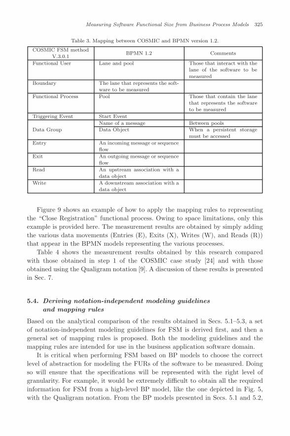
Before measuring the functional size of the C-Registration System, the rules formapping between the COSMIC concepts [3] and the modeling constructs of BPMN1.2 [11] must be defined. From the analysis in Figs. 7 and 8, some of these rulescan be derived. Table 3 shows all the rules that have been defined based on thatanalysis, as well as a comparison of the definitions of the COSMIC concepts andthe BPMN constructs.
July 20, 2011 14:41 WSPC/117-IJSEKE - SPI-J111 0218-1940S0218194011005359
Measuring Software Functional Size from Business Process Models 325
Table 3. Mapping between COSMIC and BPMN version 1.2.
COSMIC FSM methodV.3.0.1
BPMN 1.2 Comments
Functional User Lane and pool Those that interact with thelane of the software to be
measured
Boundary The lane that represents the soft-ware to be measured
Functional Process Pool Those that contain the lanethat represents the softwareto be measured
Triggering Event Start Event
Data GroupName of a message Between poolsData Object When a persistent storage
must be accessed
Entry An incoming message or sequenceflow
Exit An outgoing message or sequenceflow
Read An upstream association with adata object
Write A downstream association with adata object
Figure 9 shows an example of how to apply the mapping rules to representingthe “Close Registration” functional process. Owing to space limitations, only thisexample is provided here. The measurement results are obtained by simply addingthe various data movements (Entries (E), Exits (X), Writes (W), and Reads (R))that appear in the BPMN models representing the various processes.
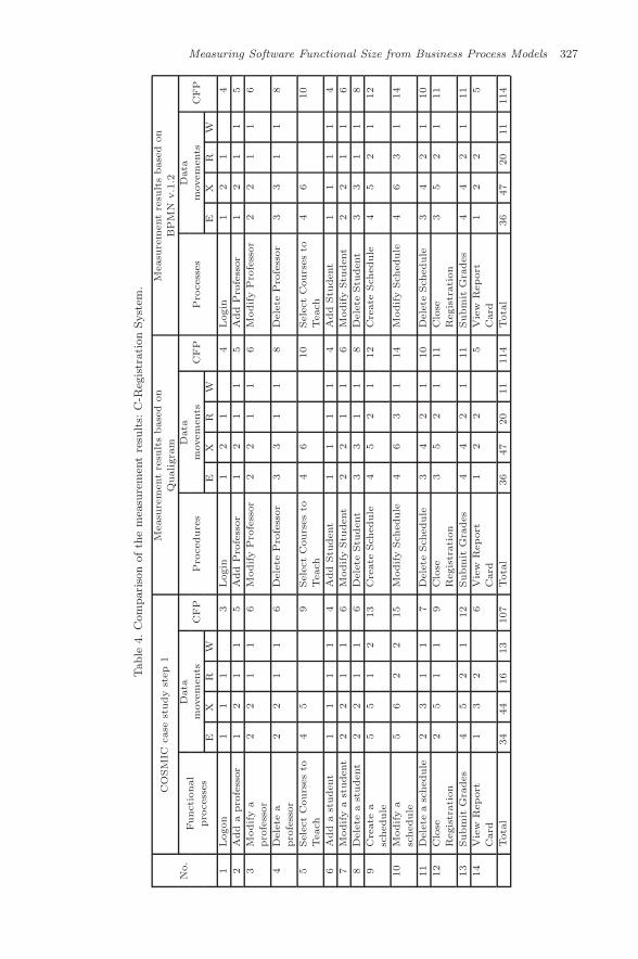
Table 4 shows the measurement results obtained by this research comparedwith those obtained in step 1 of the COSMIC case study [24] and with thoseobtained using the Qualigram notation [9]. A discussion of these results is presentedin Sec. 7.
5.4. Deriving notation-independent modeling guidelines
and mapping rules
Based on the analytical comparison of the results obtained in Secs. 5.1–5.3, a setof notation-independent modeling guidelines for FSM is derived first, and then ageneral set of mapping rules is proposed. Both the modeling guidelines and themapping rules are intended for use in the business application software domain.
It is critical when performing FSM based on BP models to choose the correctlevel of abstraction for modeling the FURs of the software to be measured. Doingso will ensure that the specifications will be represented with the right level ofgranularity. For example, it would be extremely difficult to obtain all the requiredinformation for FSM from a high-level BP model, like the one depicted in Fig. 5,with the Qualigram notation. From the BP models presented in Secs. 5.1 and 5.2,

July 20, 2011 14:41 WSPC/117-IJSEKE - SPI-J111 0218-1940S0218194011005359
326 C. Monsalve, A. Abran & A. April
C-REG-BPMN-2010-CLOSE REGISTRATION
C-Registration SystemClose Registration
author:version:status:
Carlos Monsalve1.0created
created: 05/07/2010 4:12:02 PMmodified: 13/07/2010 4:19:48 PM
c-registration.vsd
Cat
alog
Clo
se R
egis
trat
ion
Bill
ing
C-R
eg S
yste
mR
egis
trar
Verify Status
Status
RegistrationIn Progress?
Yes
RegistrationIn Progress
Get ListofStudents
InfoRequirement
List ofStudents
Count Students
At least 3 students? ProfessorSigned Up?
Yes Close CourseOffering
Yes
Transactionsfor each studentNACK
Cancel CourseOffering
No NoSchedules
ModifySchedules
Stu
dent
UpdateCatalog
CatalogUpdates
NotifyBy
SchedulesE
RX
XE
RW
X
X
XE
“CloseReg”Select
Fig. 9. Application of the mapping rules to the “Close Registration” functional process.
it is possible to conclude that a good level of granularity is achieved when modelingat what Qualigram calls the “organizational level” of abstraction.
Guideline 1. If the selected BP modeling notation offers various modeling levelsof abstraction, choose one that allows depiction of the BP workflow, including itsactivities, roles, events, and flow of information.
Modeling rules Q.BA2, Q.BA6, and BPMN3 are related to the same conceptsand can be generalized as follows:Guideline 2. Consider any peer software component that interacts with the mea-sured software as an external participant (i.e. external role).
Modeling rules Q.BA3 and BPMN1 are very similar, and can be generalized asfollows:Guideline 3. Represent any logical instruction set that is worth detailing as aseparate BP workflow.
Modeling rules Q.BA4 and BPMN4 share some concepts, and can be generalizedas follows:Guideline 4. Represent any user of the software, external to the organization, asan external participant (i.e. external role).
July 20, 2011 14:41 WSPC/117-IJSEKE - SPI-J111 0218-1940S0218194011005359
Measuring Software Functional Size from Business Process Models 327
Table
4.C
om
pari
son
ofth
em
easu
rem
ent
resu
lts:
C-R
egis
trati
on
Syst
em.
CO
SM
ICcase
study
step
1M
easu
rem
ent
resu
lts
base
don
Measu
rem
ent
resu
lts
base
don
Qualigra
mB
PM
Nv.1
.2
No.
Data
Data
Data
Functi
onal
movem
ents
movem
ents
movem
ents
pro
cess
es
EX
RW
CFP
Pro
cedure
s
EX
RW
CFP
Pro
cess
es
EX
RW
CFP
1Logon
11
13
Login
12
14
Login
12
14
2A
dd
apro
fess
or
12
11
5A
dd
Pro
fess
or
12
11
5A
dd
Pro
fess
or
12
11
5
3M
odify
a
pro
fess
or
22
11
6M
odify
Pro
fess
or
22
11
6M
odify
Pro
fess
or
22
11
6
4D
ele
tea
pro
fess
or
22
11
6D
ele
teP
rofe
ssor
33
11
8D
ele
teP
rofe
ssor
33
11
8
5Sele
ct
Cours
es
to
Teach
45
9Sele
ct
Cours
es
to
Teach
46
10
Sele
ct
Cours
es
to
Teach
46
10
6A
dd
ast
udent
11
11
4A
dd
Stu
dent
11
11
4A
dd
Stu
dent
11
11
4
7M
odify
ast
udent
22
11
6M
odify
Stu
dent
22
11
6M
odify
Stu
dent
22
11
6
8D
ele
tea
student
22
11
6D
ele
teStu
dent
33
11
8D
ele
teStu
dent
33
11
8
9C
reate
a
schedule
55
12
13
Cre
ate
Sch
edule
45
21
12
Cre
ate
Sch
edule
45
21
12
10
Modify
a
schedule
56
22
15
Modify
Sch
edule
46
31
14
Modify
Sch
edule
46
31
14
11
Dele
tea
schedule
23
11
7D
ele
teSch
edule
34
21
10
Dele
teSch
edule
34
21
10
12
Clo
se
Regis
trati
on
25
11
9C
lose
Regis
trati
on
35
21
11
Clo
se
Regis
trati
on
35
21
11
13
Subm
itG
rades
45
21
12
Subm
itG
rades
44
21
11
Subm
itG
rades
44
21
11
14
Vie
wR
eport
Card
13
26
Vie
wR
eport
Card
12
25
Vie
wR
eport
Card
12
25
Tota
l34
44
16
13
107
Tota
l36
47
20
11
114
Tota
l36
47
20
11
114
July 20, 2011 14:41 WSPC/117-IJSEKE - SPI-J111 0218-1940S0218194011005359
328 C. Monsalve, A. Abran & A. April
In addition, modeling rule BPMN4 includes some relevant considerations thatcan be generalized as follows:Guideline 5. Represent any user of the software, internal to the organization, asan internal participant (i.e. internal role).
Modeling rules Q.BA5 and BPMN2 can be generalized as follows:Guideline 6. Represent the measured software as an internal participant (i.e. inter-nal role).
Modeling rules Q.BA7 and BPMN7 present some concepts in common and canbe generalized as follows:Guideline 7. Anytime relevant data must be retrieved from or written to persistentstorage, represent that type of action as a resource or as a data object used in theBP. Associate the resource or data object with the corresponding modeling construct,and then differentiate a retrieval action from a writing action in an appropriate way.
Modeling rule Q.BA8 is relevant and should be generalized:Guideline 8. If the BP being modeled requires, at its inception, that informationbe entered by the user triggering it, represent the initial submission of informationas the triggering event.
Modeling rules Q.BA9 and BPMN5 are very similar, and can be generalized asfollows:Guideline 9. All the error conditions identified by the internal participant (i.e.internal role) representing the measured software must be collected by a single mod-eling construct associated with the same internal participant, before reporting thoseconditions to another participant (i.e. role).
Modeling rules Q.BA10, BPMN6, and BPMN8 share common concepts, and canbe generalized as follows:Guideline 10. Avoid representing flows of information between participants (i.e.roles), whether they are internal or external, when those flows are only aimed atindicating a possible end to the workflow, or a repetition of it.
Comparing Tables 2 and 3, it is possible to generalize the mapping rules for thebusiness application software domain, as presented in Table 5.
The COSMIC data group concept presents two mapping options, as describedin Table 5. The first option is to map a data group to the information provided aspart of a flow. This option is valid for the data groups that are exchanged betweenthe measured software and the functional users. The second option is to map a datagroup to the name of a resource or data object. This option is valid for the datagroups that are retrieved from, or moved to, a persistent storage by the measuredsoftware.

July 20, 2011 14:41 WSPC/117-IJSEKE - SPI-J111 0218-1940S0218194011005359
Measuring Software Functional Size from Business Process Models 329
Table 5. Rules for mapping between COSMIC and BP modeling notation.
COSMIC FSM method V.3.0.1 BP modeling notation
Functional User Construct that represents a role or participantBoundary The swim-lane of the measured softwareFunctional Process Business processTriggering Event Start EventData Group Information provided as part of a flow
Name of a resource or data objectEntry An incoming flowExit An outgoing flowRead A resource or data object representing the retrieval of dataWrite A resource or data object representing the writing of data
6. FSM based on a BP Model: The Real-Time Domain
The purpose of this section is to measure the functional size of the software com-ponents of the Rice Cooker Controller [34] based on a set of BP models, in orderto analyze the feasibility of using them as the source of information for the FSMof real-time software. Therefore, the scope of this measurement is given by all thesoftware requirements of the Rice Cooker Controller case study of the COSMICGroup, which is a real-time system. All its software components are at the samehierarchical level, and at a similar level of decomposition. Therefore, in thisarticle, we consider that all the software components of the Rice Cooker Controllerbelong to a single software layer. In the next subsection, the specific modeling rulesfor producing Qualigram models of real-time software for FSM purposes are pre-sented. In addition, the appropriate level of abstraction of the models generated isdetermined, in accordance with the level of granularity expected by the COSMICFSM method. In Sec. 6.2, the mapping rules between COSMIC and Qualigram forthe real-time domain are defined, in order to arrive at a measure of the functionalsize of the software components of the Rice Cooker Controller.
6.1. Modeling rules for the real-time domain
The modeling rules presented in Sec. 5.1 for the business application domain canbe adapted as follows:
Modeling Rule Q.RT1. Represent the various software components of the real-time system as one process at the top level of abstraction (i.e. the strategic level ).Modeling Rule Q.RT2. Consider any hardware interacting with the software asan external entity.Modeling Rule Q.RT3. Consider as a procedure any software requirement that:(1) presents an autonomous functionality (i.e. does not depend on other softwarecomponents); and (2) can be detailed more deeply.
Figure 10 shows the top-level model of the software components of the RiceCooker Controller.
July 20, 2011 14:41 WSPC/117-IJSEKE - SPI-J111 0218-1940S0218194011005359
330 C. Monsalve, A. Abran & A. April
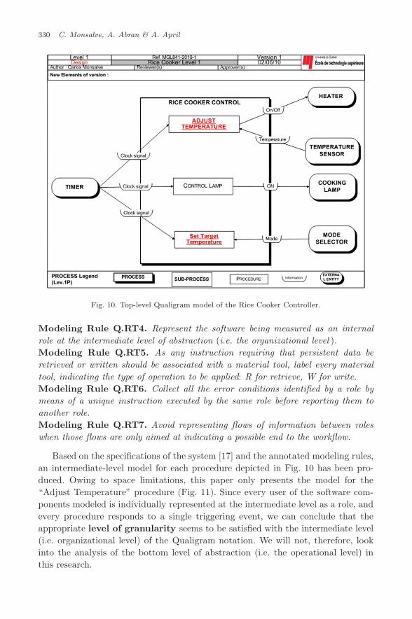
Fig. 10. Top-level Qualigram model of the Rice Cooker Controller.
Modeling Rule Q.RT4. Represent the software being measured as an internalrole at the intermediate level of abstraction (i.e. the organizational level ).Modeling Rule Q.RT5. As any instruction requiring that persistent data beretrieved or written should be associated with a material tool, label every materialtool, indicating the type of operation to be applied: R for retrieve, W for write.Modeling Rule Q.RT6. Collect all the error conditions identified by a role bymeans of a unique instruction executed by the same role before reporting them toanother role.Modeling Rule Q.RT7. Avoid representing flows of information between roleswhen those flows are only aimed at indicating a possible end to the workflow.
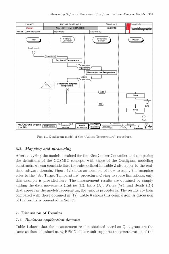
Based on the specifications of the system [17] and the annotated modeling rules,an intermediate-level model for each procedure depicted in Fig. 10 has been pro-duced. Owing to space limitations, this paper only presents the model for the“Adjust Temperature” procedure (Fig. 11). Since every user of the software com-ponents modeled is individually represented at the intermediate level as a role, andevery procedure responds to a single triggering event, we can conclude that theappropriate level of granularity seems to be satisfied with the intermediate level(i.e. organizational level) of the Qualigram notation. We will not, therefore, lookinto the analysis of the bottom level of abstraction (i.e. the operational level) inthis research.
July 20, 2011 14:41 WSPC/117-IJSEKE - SPI-J111 0218-1940S0218194011005359
Measuring Software Functional Size from Business Process Models 331
Fig. 11. Qualigram model of the “Adjust Temperature” procedure.
6.2. Mapping and measuring
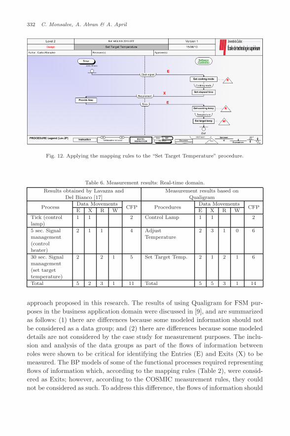
After analyzing the models obtained for the Rice Cooker Controller and comparingthe definitions of the COSMIC concepts with those of the Qualigram modelingconstructs, we can conclude that the rules defined in Table 2 also apply to the real-time software domain. Figure 12 shows an example of how to apply the mappingrules to the “Set Target Temperature” procedure. Owing to space limitations, onlythis example is provided here. The measurement results are obtained by simplyadding the data movements (Entries (E), Exits (X), Writes (W), and Reads (R))that appear in the models representing the various procedures. The results are thencompared with those obtained in [17]. Table 6 shows this comparison. A discussionof the results is presented in Sec. 7.
7. Discussion of Results
7.1. Business application domain
Table 4 shows that the measurement results obtained based on Qualigram are thesame as those obtained using BPMN. This result supports the generalization of the
July 20, 2011 14:41 WSPC/117-IJSEKE - SPI-J111 0218-1940S0218194011005359
332 C. Monsalve, A. Abran & A. April
Fig. 12. Applying the mapping rules to the “Set Target Temperature” procedure.
Table 6. Measurement results: Real-time domain.
Results obtained by Lavazza and Measurement results based onDel Bianco [17] Qualigram
ProcessData Movements
CFP ProceduresData Movements
CFPE X R W E X R W
Tick (controllamp)
1 1 2 Control Lamp 1 1 2
5 sec. Signalmanagement(controlheater)
2 1 1 4 AdjustTemperature
2 3 1 0 6
30 sec. Signalmanagement(set targettemperature)
2 2 1 5 Set Target Temp. 2 1 2 1 6
Total 5 2 3 1 11 Total 5 5 3 1 14
approach proposed in this research. The results of using Qualigram for FSM pur-poses in the business application domain were discussed in [9], and are summarizedas follows: (1) there are differences because some modeled information should notbe considered as a data group; and (2) there are differences because some modeleddetails are not considered by the case study for measurement purposes. The inclu-sion and analysis of the data groups as part of the flows of information betweenroles were shown to be critical for identifying the Entries (E) and Exits (X) to bemeasured. The BP models of some of the functional processes required representingflows of information which, according to the mapping rules (Table 2), were consid-ered as Exits; however, according to the COSMIC measurement rules, they couldnot be considered as such. To address this difference, the flows of information should
July 20, 2011 14:41 WSPC/117-IJSEKE - SPI-J111 0218-1940S0218194011005359
Measuring Software Functional Size from Business Process Models 333
include the data groups, and it must be determined during the measurement processwhether or not each of the information flows corresponds to a data group. Othermeasurement differences were related to details of the functional procedures thatwere required to be represented as part of the BP models, even though they werenot considered in the interpretation of the specifications in the case study. Mostof the rest of this subsection discusses the results based on BPMN 1.2 obtained inSec. 5.3.
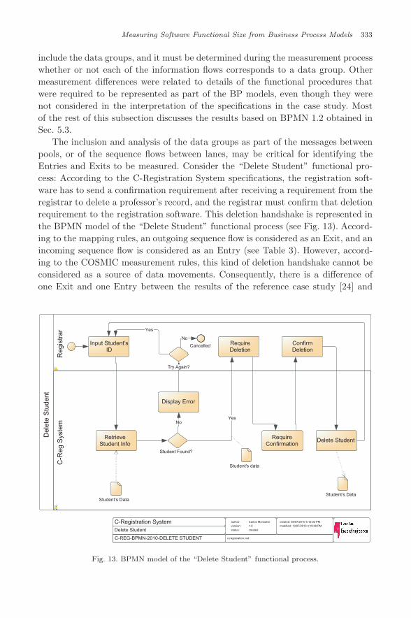
The inclusion and analysis of the data groups as part of the messages betweenpools, or of the sequence flows between lanes, may be critical for identifying theEntries and Exits to be measured. Consider the “Delete Student” functional pro-cess: According to the C-Registration System specifications, the registration soft-ware has to send a confirmation requirement after receiving a requirement from theregistrar to delete a professor’s record, and the registrar must confirm that deletionrequirement to the registration software. This deletion handshake is represented inthe BPMN model of the “Delete Student” functional process (see Fig. 13). Accord-ing to the mapping rules, an outgoing sequence flow is considered as an Exit, and anincoming sequence flow is considered as an Entry (see Table 3). However, accord-ing to the COSMIC measurement rules, this kind of deletion handshake cannot beconsidered as a source of data movements. Consequently, there is a difference ofone Exit and one Entry between the results of the reference case study [24] and
C-REG-BPMN-2010-DELETE STUDENT
C-Registration SystemDelete Student
author:version:status:
Carlos Monsalve1.0created
created: 05/07/2010 4:12:02 PMmodified: 13/07/2010 4:19:48 PM
c-registration.vsd
Del
ete
Stu
dent
Reg
istr
arC
-Reg
Sys
tem
Input Student’sID
RetrieveStudent Info
Student’s Data
Student Found?
Yes
RequireDeletion
Student's data
RequireConfirmation
ConfirmDeletion
Delete Student
Student’s Data
No
Display Error
Try Again?
Yes
Cancelled
No
Fig. 13. BPMN model of the “Delete Student” functional process.
July 20, 2011 14:41 WSPC/117-IJSEKE - SPI-J111 0218-1940S0218194011005359
334 C. Monsalve, A. Abran & A. April
those obtained in this paper (see Table 4). To address this difference, the messagesand sequence flows should include the data groups, and it must be determinedduring the measurement process whether or not each of the messages or sequenceflows corresponds to a data group. Something similar happens with the “DeleteProfessor”, “Delete Schedule”, and “Login” functional processes.
The difference of one Exit (Table 4) for the “Select Courses” functional process(see Fig. 7) is caused by the fact that the reference case study apparently considersthat the course offering information is updated in the Catalog System every timethis system is consulted about potential conflicts between the offerings selectedby the professor. In this research, these two functions have been disaggregated,because the course offerings should be updated only after the professor has resolvedthe conflicts.
There is a difference of one Read for the “Create Schedule”, “Modify Sched-ule”, and “Delete Schedule” functional processes. The reference case study does notconsider the FURs associated with verifying the status of the registration process(closed or not closed) before meeting the student’s requirement. The reason givenby the case study is the poor quality of the specifications. Even though this maybe true, we have considered the required verification in this research, because ithas been modeled as one of the tasks to be executed for these functional processes.Something similar happens with a verification FUR for the “Close Registration”functional process (see Fig. 9). In addition, for the “Create Schedule” and “Mod-ify Schedule” functional processes, this research has considered that the only waya student can save a schedule is when he or she submits a set of courses to theregistration system. Therefore, an extra Entry and an extra Write have not beenconsidered to be a consequence of a “Save Schedule” FUR. It has, however, in thereference case study.
The specifications mention that during the “Close Registration” functionalprocess (see Fig. 9), it is possible that the billing system will not respond tothe requirements of the registration system. If that is the case, the specifica-tions ask that the requirement be retried an undetermined number of times.The reference case study has not considered this as a functionality to be mea-sured, probably because there is no data group associated with it. However, inthis research, it has been measured as an Entry, because the registration systemneeds to receive a message from the billing system in order to retry the require-ment.
Finally, the impact of the data groups is again evident in the measurement dif-ference that appears for the “Submit Grades” functional process. After retrievingthe list of students and retrieving the grades (two different data groups), the speci-fications ask for a display of those grades. In the BPMN model, this is representedby only one task, which displays the names of the students and their grades, and itcounts as one Exit. However, the reference case study considers two Exits, becausethere are two different data groups. Something very similar happens with the “ViewReport Card” functional process.
July 20, 2011 14:41 WSPC/117-IJSEKE - SPI-J111 0218-1940S0218194011005359
Measuring Software Functional Size from Business Process Models 335
7.2. Real-time domain
It is very likely that a BP modeling notation would not be used for modelingreal-time software, as the actual purpose of this kind of modeling notation is torepresent organizational BPs. However, it is possible to conclude from the resultsof this research that, following the correct modeling rules, clear and useful modelsrepresenting real-time software components can be produced.
The first difference between the results obtained in this research and thoseobtained in [17] (see Table 5) is caused by the way in which the two possible signalsto be sent to the heater are represented. Both options are represented as indepen-dent flows of information in the Qualigram model (see Fig. 11), and are thereforeconsidered as two Exits. However, in [17], they are considered as part of the sameExit.
Finally, the second difference appears in the “Set Target Temperature” proce-dure (see Fig. 12). The reference case study [17] considers that the elapsed time isspontaneously sent by the timer to the software controller. In the Qualigram model,the timer sends the time elapsed after receiving a requirement from the softwarecontroller. It is therefore considered as an additional Exit in this article.
8. Conclusions, Limitations, and Future Work
This research has shown the technical feasibility of using BP models for FSM withthe COSMIC measurement method (COSMIC FSM). A set of modeling rules torepresent the software components to be measured using the BPMN 1.2 modelingnotation has been defined for the business application domain. The modeling rulesfor representing real-time software in Qualigram modeling notation have also beendefined. In addition, the rules for mapping between the COSMIC concepts and boththe Qualigram and BPMN 1.2 modeling constructs have been derived. The modelingrules and mapping rules have been applied to two case studies, one for the businessapplication domain and the other for the real-time domain. The results have beencompared with those obtained in previous works for the same case studies.
The modeling rules for the business application domain have been generalized,producing a set of notation-independent BP modeling guidelines for FSM purposes.However, the strengths of these guidelines should be further tested with other pop-ular BP modeling notations. Moreover, to increase the validity of the guidelines,they should be tested with other case studies rather than only testing with theC-Registration System.
The measurement results show that, following the modeling rules and using themapping rules, BP models might be used successfully for FSM in both domains.Moreover, there is evidence that the measurement results are not affected by theBP modeling notation selected. However, the strength of these results should befurther tested with other case studies; preferably case studies where it is possibleto cover business processes that are typically modeled in the industry. The results
July 20, 2011 14:41 WSPC/117-IJSEKE - SPI-J111 0218-1940S0218194011005359
336 C. Monsalve, A. Abran & A. April
obtained using the mapping rules may be compared to the results obtained byexpert COSMIC measurers, if that is the case.
In the business application domain, a small additional effort is foreseen for mod-eling the BP for FSM purposes when using BPMN. The BPMN models generatedin this research do not present important differences with those that are typi-cally generated in industry. A different scenario is foreseen when using Qualigram.The Qualigram intermediate-level models (i.e. procedure models) generated in thisresearch have required representing the software being measured as another role.Organizations using Qualigram typically do not represent any information systemas a role in their intermediate-level models. Therefore, using the proposed mod-eling rules for Qualigram probably earthier will require a change in the modelingparadigm of organizations (for new BP models), or a rework of the intermediate-level models (for already existent BP models). These conclusions are some of theissues that should be tested in the future case studies.
The proposed approach might be very useful at the early stages of a softwareproject; therefore, it needs to be tested against other case studies that are based onhigh-level specifications typically used at an early stage of the software developmentprocess. It will also be necessary to perform more case studies, in order to: (1) val-idate the generalization of the modeling rules and mapping rules for the businessapplication domain; (2) study the additional effort required for the modeler andthe organization for applying the modeling rules; (3) evaluate the stability of usingBP models, which typically change in response to the dynamics of the organization,for FSM as a means for estimating effort; and (4) analyze the advantages and dis-advantages of using FSM results as a vehicle to estimate effort based on businessprocesses.
References
1. ISO/IEC, 14143-1:1998, Information technology — software measurement — func-tional size measurement, Part 1: Definition of concepts, Switzerland (InternationalOrganization for Standardization, 2000).
2. A. Abran, Software Metrics and Software Metrology (John Wiley & Sons Interscienceand IEEE-CS Press, 2010).
3. COSMIC, The COSMIC functional size measurement method version 3.0.1, measure-ment manual (the COSMIC implementation guide for ISO/IEC 19761: 2003). (TheCommon Software Measurement International Consortium (COSMIC), 2009).
4. ISO/IEC, 19761:2003 software engineering — COSMIC-FFP — a functional size mea-surement method, Switzerland (International Organization for Standardization, 2003).
5. H. C. Mayr, C. Kop and D. Esberger, Business process modeling and requirementsmodeling, in Proc. First International Conference on the Digital Society (ICDS ’07),Guadeloupe, 2007, pp. 8–8.
6. M. Indulska, P. Green, J. Recker and M. Rosemann, Business process modeling: Per-ceived benefits, in Proc. 28th International Conference on Conceptual Modeling (ER2009), Gramado, Brazil, 2009, pp. 458–471.
7. M. Dumas, W. van der Aalst and A. Ter Hofstede, Process-aware Information Sys-tems: Bridging People and Software Through Process Technology (Wiley-Interscience,Hoboken, 2005).
July 20, 2011 14:41 WSPC/117-IJSEKE - SPI-J111 0218-1940S0218194011005359
Measuring Software Functional Size from Business Process Models 337
8. IIBA, A Guide to the Business Analysis Body of Knowledge (BABOK guide) (Inter-national Institute of Business Analysis (IIBA), Toronto, 2009).
9. C. Monsalve, A. Abran and A. April, Functional size measurement with business pro-cess models: The business application domain, in Proc. International Conferences onSoftware Measurement (IWSM/MetriKon/Mensura 2010), Stuttgart, Germany, 2010,pp. 270–290.
10. M. Kaya, E-cosmic: A business process model based functional size estimationapproach in Department of Information Systems, Ankara (Middle East Technical Uni-verstiy, 2010).
11. OMG, OMG business process model and notation (BPMN), version 1.2 (Object Man-agement Group, 2009).
12. M. Daneva, Measuring reuse of SAP requirements: A model-based approach, in Pro-ceedings of the 1999 Symposium on Software reusability, Los Angeles, California, 1999.
13. IFPUG, Function point counting manual, release 4.0, Westerville, Ohio (InternationalFunction Point Users Group (IFPUG), 1994).
14. A. Scheer, O. Thomas and O. Adam, Process modeling using event-driven processchains, in Process-aware information systems: Bridging people and software throughprocess technology (Wiley-Interscience, 2005), pp. 119–145.
15. O. Demirors and C. Gencel, A comparison of size estimation techniques applied earlyin the life cycle, in Proc. 11th European Software Process Improvement Conference,(EuroSPI 2004), Trondheim, Norway, 2004, pp. 184–194.
16. B. Marın, G. Giachetti and O. Pastor, Measurement of functional size in concep-tual models: A survey of measurement procedures based on COSMIC, in Proc.IWSM/Metrikon/Mensura ’08: International Conferences on Software Process andProduct Measurement, Munich, Germany, 2008, pp. 170–183.
17. L. Lavazza and V. Bianco, A case study in COSMIC functional size measurement:The rice cooker revisited, in Proc. IWSM ’09 /Mensura ’09: International Conferenceson Software Process and Product Measurement, Amsterdam, The Netherlands, 2009,pp. 101–121.
18. OMG, OMG unified modeling language (OMG UML), superstructure, version 2.3,(Object Management Group, 2010).
19. A. Sellami and H. Ben-Abdallah, Functional size of use case diagrams: A fine-grainmeasurement, in Proc. ICSEA ’09: 2009 Fourth International Conference on SoftwareEngineering Advances, 2009, pp. 282–288.
20. K. G. van den Berg, T. Dekkers and R. Oudshoorn, Functional size measurementapplied to UML-based user requirements, in Proc. Software Measurement EuropeanForum (SMEF 2005), Rome, 2005, pp. 69–80.
21. C. Berger and S. Guillard, La redaction graphique des procedures: Demarche et tech-niques de description des processus (Association Francaise de Normalisation, AFNOR,Paris, 2000).
22. P. Dumas and G. Charbonnel, La methode ossad: Pour maıtriser les technologies del’information (Les Editions D’Organisation, 1990).
23. V. D. Antonellis and B. Zonta, A disciplined approach to office analysis, IEEE Trans.Softw. Eng. 16(8) (1990) 822–828.
24. GELOG-ETS, Software functional size with ISO 19761:2003 COSMIC-FFP mea-surement method, proposed measurement etalon: C-registration system, Canada(Software Engineering Research Laboratory, Ecole de Technologie Superieure,2008).
25. W. Sedera, G. Gable, M. Rosemann and R. Smyth, A success model for businessprocess modeling: Findings from a multiple case study, in Proc. Eighth Pacific AsiaConference on Information Systems, Shanghai, China, 2004.
July 20, 2011 14:41 WSPC/117-IJSEKE - SPI-J111 0218-1940S0218194011005359
338 C. Monsalve, A. Abran & A. April
26. C. Monsalve, A. April and A. Abran, Representing unique stakeholder perspectives inBPM notations, in Proc. 8th ACIS International Conference on Software EngineeringResearch, Management and Applications (SERA 2010), Montreal, 2010, pp. 42–49.
27. P. Harmon and C. Wolf, The state of business process management 2010, in ABPTrends Report (2010).
28. J. Recker, BPMN modeling–who, where, how and why, Business Process Trends(2008).
29. S. White, Introduction to BPMN, Business Process Trends (2004).30. H. Smith and P. Fingar, Business process management: The third wave (Meghan-Kiffer
Press, Tampa, 2007).31. J. Recker, M. Indulska, M. Rosemann and P. Green, How good is BPMN really?
Insights from theory and practice, in Proc. 14th European Conference on InformationSystems (ECIS’ 06), Goeteborg, Sweden, 2006.
32. J. Recker, M. Rosemann, M. Indulska and P. Green, Business process modeling: Acomparative analysis, Journal of the Association for Information Systems 10(4) (2009)333–363.
33. M. Zur Muehlen and L. M. Jan Recker, How much language is enough? Theoreticaland practical use of the business process modeling notation, in Proc. CAiSE ’08:20th international conference on Advanced Information Systems Engineering, Berlin,Heidelberg, 2008, pp. 465–479.
34. COSMIC, Case study: Rice cooker (COSMIC group, 2008).35. OMG, Business process model and notation (BPMN) version 2.0 (Object Management
Group (OMG), 2010).36. B. Silver, BPMN Method and Style (Cody-Cassidy Press, Aptos, 2009).

Copyright of International Journal of Software Engineering & Knowledge Engineering is the property of World
Scientific Publishing Company and its content may not be copied or emailed to multiple sites or posted to a
listserv without the copyright holder's express written permission. However, users may print, download, or
email articles for individual use.