measuring positioning - bogen · bogen electronic gmbh pe se 12-13 1163 e e f (0)30 81 00 02-0 (0)...
TRANSCRIPT
Magnetics that count
BOGEN Electronic GmbH · Potsdamer Straße 12-13 · 14163 Berlin · Germany Fon +49 (0)30 81 00 02-0 · Fax +49 (0)30 81 00 02-60 · [email protected] · www.bogen-electronic.com
AKS
16 -
Rev1
_7 (2
018/
05/3
1)
Features
• 18 to 20 Bit absolute resolution
• 16 Bit incremental resolution
• Small dimensions for space-saving implementation
• Resistant against contamination, vibrations, temperature
fluctuations, humidity
• No wear from usage
• Corresponding scales in various diameters
and lengths
Motion control with AKS16 accurate - robust - flexible
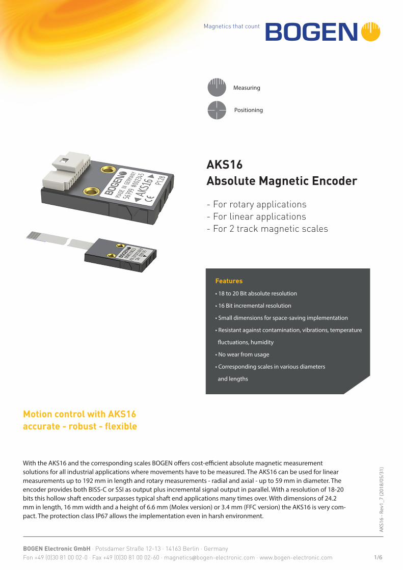
AKS16 Absolute Magnetic Encoder
- For rotary applications- For linear applications- For 2 track magnetic scales
Measuring
Positioning
1/6
With the AKS16 and the corresponding scales BOGEN offers cost-efficient absolute magnetic measurement solutions for all industrial applications where movements have to be measured. The AKS16 can be used for linear measurements up to 192 mm in length and rotary measurements - radial and axial - up to 59 mm in diameter. The encoder provides both BISS-C or SSI as output plus incremental signal output in parallel. With a resolution of 18-20 bits this hollow shaft encoder surpasses typical shaft end applications many times over. With dimensions of 24.2 mm in length, 16 mm width and a height of 6.6 mm (Molex version) or 3.4 mm (FFC version) the AKS16 is very com-pact. The protection class IP67 allows the implementation even in harsh environment.
Magnetics that count
BOGEN Electronic GmbH · Potsdamer Straße 12-13 · 14163 Berlin · Germany Fon +49 (0)30 81 00 02-0 · Fax +49 (0)30 81 00 02-60 · [email protected] · www.bogen-electronic.com
AKS
16 -
Rev1
_7 (2
018/
05/3
1)
Features
Absolute resolutionSmall 18 BitMedium 19 BitLarge 20 Bit
Commutation signal For 1 to 16 pole pairs (UVW)
Rotation speedResolution 18 Bit: up to 24,000 rpmResolution 19 Bit: up to 12,000 rpmResolution 20 Bit: up to 6,000 rpm
Optimal distance magnetic target sensing head
0.4 mm
Supply voltage 5 V ± 5 %Maximum output load 50 mA per ChannelEnergy consumption (without load)
<60 mA ± 5 % (UB = 5,0 V)
LEDGreen LED = device onRed LED = bad set up (adjustment required)
Operating temperature -20 to +60 °CStorage temperature -40 to +80 °CProtection class IP67 (with FFC connector)ABZ Incremental resolution
4 and 262144 in steps of four based on pole pitch
Weight ca. 2.4 gPole pitch 1.28 or 1.50 mm
Output Signals ABZSignals / Inverted signals A, /A, B, /B, Z, /ZSignal amplitude (without load) RS422 (± 5 V)Phase shift A and B 90° ± 10° electricalSignal period length Z 90°
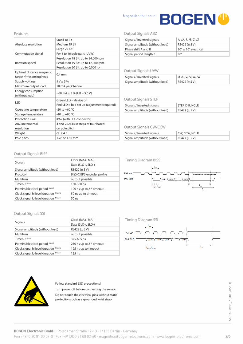
Output Signals BISS
SignalsClock (MA+, MA-)Data (SLO+, SLO-)
Signal amplitude (without load) RS422 (± 5 V)Protocol BISS-C BP3 encoder profileMultiturn output possibleTimeout (ttos) 150-380 nsPermissible clock period (tMAS) 100 ns up to 2 * timeoutClock signal hi level duration (tMASh) 50 ns up to timeoutClock signal lo level duration (tMASl) 50 ns
2/6
Output Signals SSI
SignalsClock (MA+, MA-)Data (SLO+, SLO-)
Signal amplitude (without load) RS422 (± 5 V)Multiturn output possibleTimeout (ttos) 375-605 nsPermissible clock period (tMAS) 250 ns up to 2 * timeoutClock signal hi level duration (tMASh) 125 ns up to timeoutClock signal lo level duration (tMASl) 125 ns
Timing Diagram BISS
Output Signals UVWSignals / Inverted signals U, /U, V, /V, W, /WSignal amplitude (without load) RS422 (± 5 V)
Output Signals STEPSignals / Inverted signals STEP, DIR, NCLRSignal amplitude (without load) RS422 (± 5 V)
Output Signals CW/CCWSignals / Inverted signals CW, CCW, NCLRSignal amplitude (without load) RS422 (± 5 V)
Timing Diagram SSI
Follow standard ESD precautions!
Turn power off before connecting the sensor.
Do not touch the electrical pins without staticprotection such as a grounded wrist strap.
Magnetics that count
BOGEN Electronic GmbH · Potsdamer Straße 12-13 · 14163 Berlin · Germany Fon +49 (0)30 81 00 02-0 · Fax +49 (0)30 81 00 02-60 · [email protected] · www.bogen-electronic.com
AKS
16 -
Rev1
_7 (2
018/
05/3
1)
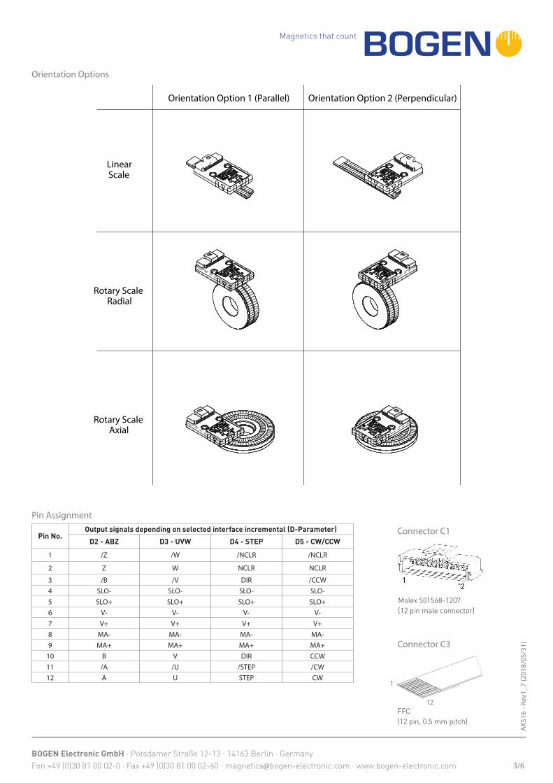
Orientation Options
Orientation Option 1 (Parallel)
Rotary ScaleRadial
Orientation Option 2 (Perpendicular)
Rotary ScaleAxial
LinearScale
Pin Assignment
Pin No.Output signals depending on selected interface incremental (D-Parameter)
D2 - ABZ D3 - UVW D4 - STEP D5 - CW/CCW
1 /Z /W /NCLR /NCLR
2 Z W NCLR NCLR
3 /B /V DIR /CCW4 SLO- SLO- SLO- SLO-5 SLO+ SLO+ SLO+ SLO+6 V- V- V- V-7 V+ V+ V+ V+8 MA- MA- MA- MA-9 MA+ MA+ MA+ MA+
10 B V DIR CCW11 /A /U /STEP /CW12 A U STEP CW
Molex 501568-1207 (12 pin male connector)
1
12FFC(12 pin, 0.5 mm pitch)
3/6
Connector C1
Connector C3
Magnetics that count
BOGEN Electronic GmbH · Potsdamer Straße 12-13 · 14163 Berlin · Germany Fon +49 (0)30 81 00 02-0 · Fax +49 (0)30 81 00 02-60 · [email protected] · www.bogen-electronic.com
AKS
16 -
Rev1
_7 (2
018/
05/3
1)
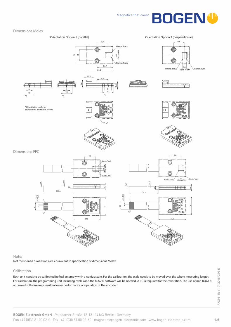
Dimensions Molex
Orientation Option 2 (perpendicular)Orientation Option 1 (parallel) 9,8
3,6 Track Width Master TrackNonius Track
10
16
14,2
24,2
3,6
Tr
ack
Wid
th
9,8
Master Track
Nonius Track
5,35
6
3,4
6,6
10
9,8
*)
M2,5
6 10
*)
6
10 *)
*) Installation marks for scale widths 6 mm and 10 mm
4/6
Dimensions FFC
3,4
134 ±5
0,3
0,1
5
2,9
6,5
pitc
h 0,
5
16
24,2
1
12
3,6
Tr
ack
Wid
th
9,8
Master Track
Nonius Track
3,4
134 ±5
0,3
0,1
5
2,9
6,5
pitc
h 0,
5
24,2
16
1
12
9,8
3,6 Track WidthNonius Track Master Track
Note:Not mentioned dimensions are equivalent to specification of dimensions Molex.
CalibrationEach unit needs to be calibrated in final assembly with a nonius scale. For the calibration, the scale needs to be moved over the whole measuring length. For calibration, the programming unit including cables and the BOGEN software will be needed. A PC is required for the calibration. The use of non BOGEN approved software may result in losser performance or operation of the encoder!
Magnetics that count
BOGEN Electronic GmbH · Potsdamer Straße 12-13 · 14163 Berlin · Germany Fon +49 (0)30 81 00 02-0 · Fax +49 (0)30 81 00 02-60 · [email protected] · www.bogen-electronic.com
AKS
16 -
Rev1
_7 (2
018/
05/3
1)
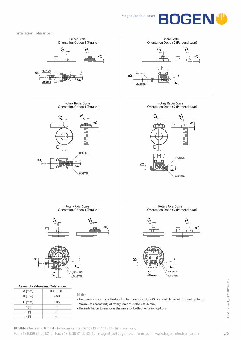
Installation Tolerances
Assembly Values and TolerancesA [mm] 0.4 ± 0.05
B [mm] ±0.5
C [mm] ±0.5
F [°] ±1G [°] ±1H [°] ±1
Note:• For tolerance purposes the bracket for mounting the AKS16 should have adjustment options.• Maximum eccentricity of rotary scale must be < 0.06 mm.• The installation tolerance is the same for both orientation options
5/6
G
C
A
H
B
F
NONIUS
MASTER
G
C
A
H
B
F
NONIUS
MASTER
G
A
H
C
B
F
NONIUS
MASTER
G
A
H
C
B
F
NONIUS
MASTER
G
F
B NONIUS
MASTER
A
HG
F
B NONIUS
MASTER
A
H
Linear ScaleOrientation Option 1 (Parallel)
Rotary Radial ScaleOrientation Option 1 (Parallel)
Rotary Axial ScaleOrientation Option 1 (Parallel)
Rotary Axial ScaleOrientation Option 2 (Perpendicular)
Rotary Radial ScaleOrientation Option 2 (Perpendicular)
Linear ScaleOrientation Option 2 (Perpendicular)

Magnetics that count
BOGEN Electronic GmbH · Potsdamer Straße 12-13 · 14163 Berlin · Germany Fon +49 (0)30 81 00 02-0 · Fax +49 (0)30 81 00 02-60 · [email protected] · www.bogen-electronic.com
AKS
16 -
Rev1
_7 (2
018/
05/3
1)
Order Code
- O P C
Parameters
AKS16
Code (1) Explanation (1)
O Orientation OptionO1 ParallelO2 Perpendicular
P Pole Pitch [mm]P1.28 1.28 mmP1.50 1.50 mm
C ConnectorC1 Molex 12 pinC3.142 FFC 12 pin, 0.5 mm pitch, length 142 mm (2)
Ordering Example
AKS16-O1P1.28C1AKS16 Magnetic Sensing Head, orientation option parallel, 1.28 mm pole pitch, connector Molex 12 pin
AKS16-O2P1.28C1AKS16 Magnetic Sensing Head, orientation option perpendicular, 1.28 mm pole pitch,connector Molex 12 pin
AKS16-O1P1.28C3.142AKS16 Magnetic Sensing Head, orientation option parallel, 1.28 mm pole pitch, connector12 pin FFC, 0.5 mm pole pitch, length 142 mm
Para
met
ers
6/6
(1) standard parameters are bold(2) other lengths on request
Parameters to be programmed by Customer (3)
Code (4) Explanation (4)
Size
Z1 16/15 Nonius
Z2 32/31 Nonius
Z3 64/63 Nonius
Interface AbsoluteA1 BISSA2 SSI
Interface Incremental
D1 None (on request)
D2.<C>ABZ (<C> counts of scale, value between 4 and 262144 in steps of 4, default is 16384)
D3 BLDC motor commutation (UVW) (on request)D4 Step / direction (on request)D5 CW / CCW Incremental (on request)
Para
met
ers
(3) Parameters have to be set by customer before calibration. Programmable with the programming unit (order no. 00052040).(4) Preset parameters are bold.
Optional Accessory00052040: Programming unit (includes adapter and cable)00022305: Receptacle connector housing 12 pol (Molex Part No.: 501330-1200)00022306: Cable assembly 28 AWG, 300 mm (Molex Part No.: 92001-1198)
Optional Accessory – linear and rotary scalesSee separate data sheets of scales for further possibilities.Data sheet LMSN (linear) Data sheet RMSN (rotary)