measuring and control technology for the production of ... · measuring and control technology for...
TRANSCRIPT
www.sikora.net
Measuring and control technology for the production of data cables, automotive cables and building wires
4
www.sikora.net
5
www.sikora.net
Content
Introduction 2
1 PREHEATER 6000 3 Preheating system
2 CENTERVIEW 8000 4 Measurement of the wall thickness, eccentricity, diameter and ovality
3 LASER Series 2000 XY/T/FR 6 LASER Series 2000 XY-models for 2-axis-diameter measurement LASER Series 2000 T-models for 3-axis-diameter measurement LASER Series 2000 F/R-models for flat and round cables
4 LASER Series 6000 8 High-speed diameter measurement Detection of lumps and neckdowns
5 TIGER LASER 6010 XY 10 Measurement of the diameter and lump inspection
6 LUMP 2000 11 Detection of lumps and neckdowns in 2 or 3 planes
7 SPARK 2000/6000 12 High frequency (HF) and direct current (DC) spark testers according to standards AS, BS, CS, CENELEC, EN, UL, VDE
8 LENGTH 6000 14 Length measuring system
9 CAPACITANCE 2000 15 Capacitance measuring devices with single and multi-zone electrode for ultra high frequency and length resolution as well as bare patch detection
10 X-RAY 6000 PRO/BASIC 17 Measurement of the wall thickness, eccentricity, diameter and ovality of single and multi layer products
11 REMOTE/DISPLAY 2000 19 Basic processor system, display device
12 ECOCONTROL 600/1000/2000/6000 21 Premium processor systems for the display and control of production data

4
www.sikora.net
Since 1973 the German based SIKORA AG has been setting the standard worldwide as manufacturer of premium measur-ing and control devices for the optical fiber and wire and cable industry. Modern Laser and X-ray technologies measure precisely and reliably product parameters such as diameter, ovality, wall thickness and eccentricity. Integrated into the ex-trusion line, the measuring devices increase quality, profit-ability and process efficiency of the production.
A continuous calculation of production data helps avoiding wall thickness oversizes. The cable manufacturer consumes less insulation material while achieving a more efficient mate-rial consumption. Every micrometer of insulation material that can be saved by the use of measuring and control technology makes the production more economic and protects at the same time the scarce resources.
Innovation, technological know-how, quality and service are the four pillars of SIKORA’s company philosophy. A strong team in research and development is working continuously on the development of new technologies that help manufac-turers of data, automotive and building wires to run their pro-duction lines more efficiently and to remain competitive. All activities at SIKORA are focussed on the customer’s needs.
SIKORA is headquartered in Bremen, Germany. Here the high-quality devices are developed and manufactured. Re-garding service and sales SIKORA is globally active with offices in Brazil, China, France, India, Italy, Japan, Korea,
Introduction
Russia, Turkey, the Ukraine, USA and the United Arabic Emir-ates. In cooperation with more than 30 local representatives worldwide SIKORA serves all customer demands with regard to quality, productivity and cost saving. In addition, interna-tional service locations assure fast and reliable customer sup-port on site.
Since 1993 SIKORA has been meeting the requirements according to DIN EN ISO 9001. The certification confirms SIKORA’s focus on continuous improvement. Customer satis-faction is SIKORA’s primary objective.
Measuring devices for the production of data cables, automotive cables and building wires
The manufacture of data cables, automotive cables or build-ing wires requires a continuous monitoring of the cable pa-rameters such as the wall thickness, eccentricity, the diameter and ovality. In addition, only faultless cables shall be deliv-ered. SIKORA offers innovative, user-friendly measuring de-vices that are specifically designed for quality control of these cable types during the production process.
5
www.sikora.net
3
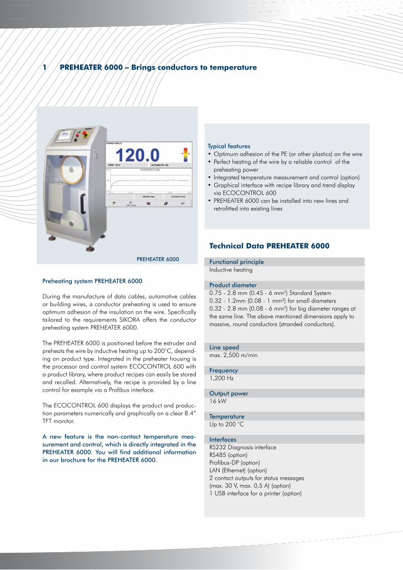
During the manufacture of data cables, automotive cables or building wires, a conductor preheating is used to ensure optimum adhesion of the insulation on the wire. Specifically tailored to the requirements SIKORA offers the conductor preheating system PREHEATER 6000.
The PREHEATER 6000 is positioned before the extruder and preheats the wire by inductive heating up to 200°C, depend-ing on product type. Integrated in the preheater housing is the processor and control system ECOCONTROL 600 with a product library, where product recipes can easily be stored and recalled. Alternatively, the recipe is provided by a line control for example via a Profibus interface.
The ECOCONTROL 600 displays the product and produc-tion parameters numerically and graphically on a clear 8.4” TFT monitor.
A new feature is the non-contact temperature mea-surement and control, which is directly integrated in the PREHEATER 6000. You will find additional information in our brochure for the PREHEATER 6000.
Typical features• Optimum adhesion of the PE (or other plastics) on the wire• Perfect heating of the wire by a reliable control of the preheating power• Integrated temperature measurement and control (option)• Graphical interface with recipe library and trend display via ECOCONTROL 600• PREHEATER 6000 can be installed into new lines and retrofitted into existing lines
Preheating system PREHEATER 6000
1 PREHEATER 6000 – Brings conductors to temperature
PREHEATER 6000
Technical Data PREHEATER 6000
Functional principleInductive heating
Product diameter 0.75 - 2.8 mm (0.45 - 6 mm²) Standard System0.32 - 1.2mm (0.08 - 1 mm²) for small diameters0.32 - 2.8 mm (0.08 - 6 mm²) for big diameter ranges at the same line. The above mentioned dimensions apply to massive, round conductors (stranded conductors).
Line speed max. 2,500 m/min
Frequency1,200 Hz
Output power16 kW
TemperatureUp to 200 °C
InterfacesRS232 Diagnosis interfaceRS485 (option)Profibus-DP (option)LAN (Ethernet) (option) 2 contact outputs for status messages (max. 30 V, max. 0,5 A) (option)1 USB interface for a printer (option)
4
www.sikora.net
4
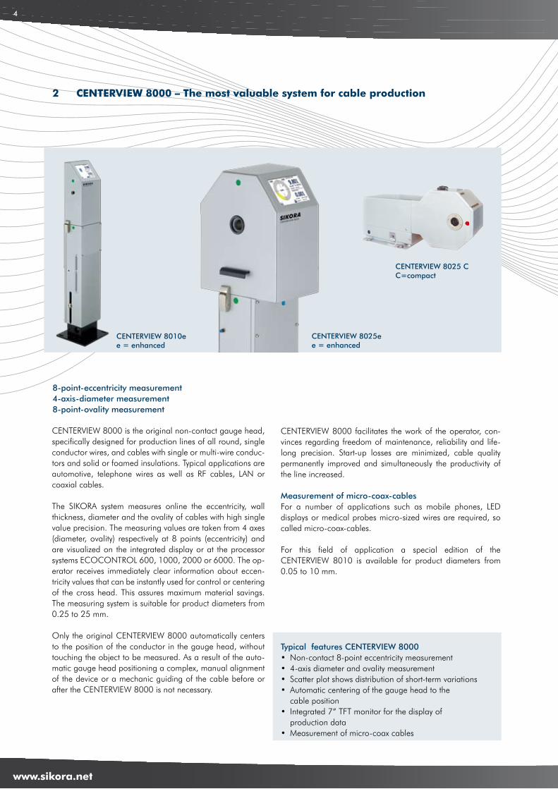
CENTERVIEW 8000 is the original non-contact gauge head, specifically designed for production lines of all round, single conductor wires, and cables with single or multi-wire conduc-tors and solid or foamed insulations. Typical applications are automotive, telephone wires as well as RF cables, LAN or coaxial cables.
The SIKORA system measures online the eccentricity, wall thickness, diameter and the ovality of cables with high single value precision. The measuring values are taken from 4 axes (diameter, ovality) respectively at 8 points (eccentricity) and are visualized on the integrated display or at the processor systems ECOCONTROL 600, 1000, 2000 or 6000. The op-erator receives immediately clear information about eccen-tricity values that can be instantly used for control or centering of the cross head. This assures maximum material savings. The measuring system is suitable for product diameters from 0.25 to 25 mm.
Only the original CENTERVIEW 8000 automatically centers to the position of the conductor in the gauge head, without touching the object to be measured. As a result of the auto-matic gauge head positioning a complex, manual alignment of the device or a mechanic guiding of the cable before or after the CENTERVIEW 8000 is not necessary.
CENTERVIEW 8000 facilitates the work of the operator, con-vinces regarding freedom of maintenance, reliability and life-long precision. Start-up losses are minimized, cable quality permanently improved and simultaneously the productivity of the line increased.
Measurement of micro-coax-cablesFor a number of applications such as mobile phones, LED displays or medical probes micro-sized wires are required, so called micro-coax-cables.
For this field of application a special edition of the CENTERVIEW 8010 is available for product diameters from 0.05 to 10 mm.
Typical features CENTERVIEW 8000• Non-contact 8-point eccentricity measurement • 4-axis diameter and ovality measurement • Scatter plot shows distribution of short-term variations• Automatic centering of the gauge head to the cable position• Integrated 7“ TFT monitor for the display of production data• Measurement of micro-coax cables
8-point-eccentricity measurement4-axis-diameter measurement8-point-ovality measurement
CENTERVIEW 8010ee = enhanced
2 CENTERVIEW 8000 – The most valuable system for cable production
CENTERVIEW 8025ee = enhanced
CENTERVIEW 8025 CC=compact

5
www.sikora.net
5
Integrated monitorIntegrated in the CENTERVIEW 8000e is as an option a 7“ TFT-Monitor, which displays production data. The operation is intuitive and menu-driven via touch screen.
The scatter plot displays the distribution of short-term variationsThe scatter plot is a visualization of the measuring values of the CENTERVIEW 8000 at the display and control system ECOCONTROL as well as at the monitor integrated in the gauge head. With the help of the scatter plot the distribu-tion of short-term variations of the eccentricity is graphically displayed. Every single dot represents a single value of the eccentricity regarding value and direction. The distribution of the scatter plot highlights the standard deviation of the ec-centricity.
A circular distribution of the single values of the eccentric-ity shows their range of variation. The representation helps to optimize the extrusion process with regard to a minimum standard deviation.
A ring type scatter plot indicates that there is a permanently rotating eccentricity value, which could be a result of a rotating (oscillating) conductor prior to the extruder crosshead.
An ellipse type distribution of the single dots can happen, if the conductor is oscillating or vibrating in one direction directly before entering the crosshead and which therefore causes eccentricity variations.
The standard way of representing eccentricity using a cross-section of the cable is very helpful for the operator when centering the crosshead. But only the display of single values in the form of a scatter plot gives the operator the necessary information to take suitable measures to optimize concentricity.
Technical Data CENTERVIEW 8000
Measuring principleNon-contact, optical/inductive with 4-axis-CCD-line technology combined with impulse-driven laser light sources Exposure time 0.25 μs
Accuracy Repeatability MeasuringProduct name Prod.-diameter Eccentricity/ Diameter Eccentricity/ Diameter rateCENTERVIEW 8010 MICRO 0.05 - 10 mm better 0.5 μm 0.1 μm 0.5 μm 0.05 μm 1,500/sCENTERVIEW 8010* 0.25 - 10 mm better 1.0 μm 1.0 μm 0.5 μm 0.1 μm 1,500/sCENTERVIEW 8025* 0.5 - 25 mm better 1.0 μm 1.0 μm 1.0 μm 0.1 μm 1,500/s
* All data apply also to the CENTERVIEW 8010/8025e and CENTERVIEW 8010/8025 C models.
Interfaces RS485 + RS232 diagnosis interfacesOption: analog interface, Profibus-DP or alternatively industrial field buses such as CANopen, Ethernet/IP, DeviceNet, ProfiNet
Power supply 115 V ... 230 V, ± 10 %, 47 to 63 Hz, other voltages are available on demand
Scatter plot shows short-term variations of the eccentricity
4
www.sikora.net
6
3 LASER Series 2000 – Having the process under control at any time
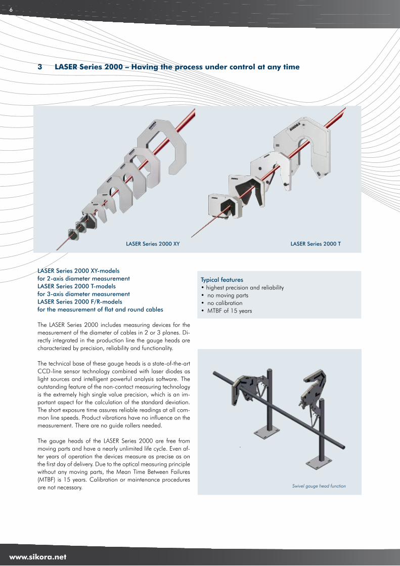
The LASER Series 2000 includes measuring devices for the measurement of the diameter of cables in 2 or 3 planes. Di-rectly integrated in the production line the gauge heads are characterized by precision, reliability and functionality.
The technical base of these gauge heads is a state-of-the-art CCD-line sensor technology combined with laser diodes as light sources and intelligent powerful analysis software. The outstanding feature of the non-contact measuring technology is the extremely high single value precision, which is an im-portant aspect for the calculation of the standard deviation. The short exposure time assures reliable readings at all com-mon line speeds. Product vibrations have no influence on the measurement. There are no guide rollers needed.
The gauge heads of the LASER Series 2000 are free from moving parts and have a nearly unlimited life cycle. Even af-ter years of operation the devices measure as precise as on the first day of delivery. Due to the optical measuring principle without any moving parts, the Mean Time Between Failures (MTBF) is 15 years. Calibration or maintenance procedures are not necessary.
Typical features• highest precision and reliability• no moving parts• no calibration• MTBF of 15 years
LASER Series 2000 XY-models for 2-axis diameter measurement LASER Series 2000 T-models for 3-axis diameter measurementLASER Series 2000 F/R-models for the measurement of flat and round cables
LASER Series 2000 XY LASER Series 2000 T
Swivel gauge head function
5
www.sikora.net
7
Specific measuring systems for your application
LASER Series 2000 XYWith the LASER Series 2000 XY SIKORA offers gauge heads for a precise diameter measurement in 2 planes. The diameter is calculated by diffraction analysis directly from the shadow image.
LASER Series 2000 TWith the LASER Series 2000 T SIKORA offers gauge heads for a precise diameter measurement, including the minimum/ maximum values, the ovality and its orientation. The ovality is accurately calculated independently from the orientation of the minimum and maximum values to the 3 measuring axes.
LASER Series 2000 F/R (Flat/Round cables)For the reliable online-acquisition of double, triple or multi-wire flat cables as well as for round conductors, the LASER Series 2000 F/R offers an exact measurement of the width and the height of the measuring object – even if the product turns up to ± 15 degree.
Technical Data LASER Series 2000
Product name Product diameter Accuracy Repeatability Exposure timeLASER 2005 XY 0.05 - 5 mm ± 0.25 μm 0.1 μm 0.2 μsLASER 2010 XY/T 0.2 - 10 mm ± 0.5 μm 0.1 μm 0.2 μsLASER 2025 XY/T 0.2 - 25 mm ± 1.0 μm 0.2 μm 0.2 μsLASER 2030 XY 0.2 - 25 mm ± 1.0 μm 0.2 μm 0.2 μsLASER 2030 F/R 0.25 - 10 mm (flat) thick ± 5.0 μm 0.5 μm 1.0 μs 0.5 - 20 mm (flat) wide 0.2 - 25 mm (round) ± 1.0 μm 0.5 μm 1.0 μsLASER 2050 XY/T 0.5 - 50 mm ± 2.5 μm/± 1.0 μm 0.5 μm 0.2 μsLASER 2100 XY/T 1.0 - 100 mm ± 5.0 μm 1.0 μm 0.2 μs
Measuring rate500/ s (higher measuring rates on demand) LASER 2005 XY: 1,200/ s
InterfacesSerial interface RS485, Setup and diagnosis interface RS232, optional analog interfaces, Profibus-DP or alternatively industrial field busses such as CANopen, Ethernet/IP, DeviceNet, ProfiNet
Power supply100 ... 240 V AC ± 10 %, 50/60 Hz
Intelligent design
Interesting is the design of the LASER Series 2000 devices. The smaller gauge heads are equipped with a unique and proven multi-slot protection. The gauge heads for bigger measuring ranges as well as all triple-axis devices are open at the bottom, which prevents water and dirt falling into the gauge head.
A special feature of the larger models is the swivelling gauge head design, which allows the head to be moved up and out of the extrusion line. The measuring heads are free from wearing parts, remain with high precision throughout their lifespan and do not require any calibration or maintenance.
4
www.sikora.net
8
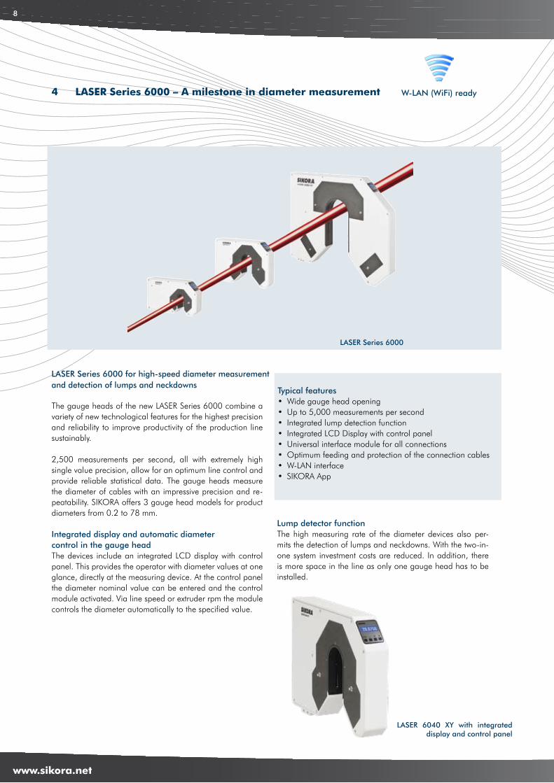
LASER Series 6000
W-LAN (WiFi) ready
The gauge heads of the new LASER Series 6000 combine a variety of new technological features for the highest precision and reliability to improve productivity of the production line sustainably.
2,500 measurements per second, all with extremely high single value precision, allow for an optimum line control and provide reliable statistical data. The gauge heads measure the diameter of cables with an impressive precision and re-peatability. SIKORA offers 3 gauge head models for product diameters from 0.2 to 78 mm.
Integrated display and automatic diameter control in the gauge headThe devices include an integrated LCD display with control panel. This provides the operator with diameter values at one glance, directly at the measuring device. At the control panel the diameter nominal value can be entered and the control module activated. Via line speed or extruder rpm the module controls the diameter automatically to the specified value.
LASER Series 6000 for high-speed diameter measurementand detection of lumps and neckdowns
4 LASER Series 6000 – A milestone in diameter measurement
Lump detector functionThe high measuring rate of the diameter devices also per-mits the detection of lumps and neckdowns. With the two-in-one system investment costs are reduced. In addition, there is more space in the line as only one gauge head has to be installed.
Typical features• Wide gauge head opening• Up to 5,000 measurements per second• Integrated lump detection function• Integrated LCD Display with control panel • Universal interface module for all connections• Optimum feeding and protection of the connection cables• W-LAN interface• SIKORA App
LASER 6040 XY with integrated display and control panel
5
www.sikora.net
9
SIKORA AppSIKORA App
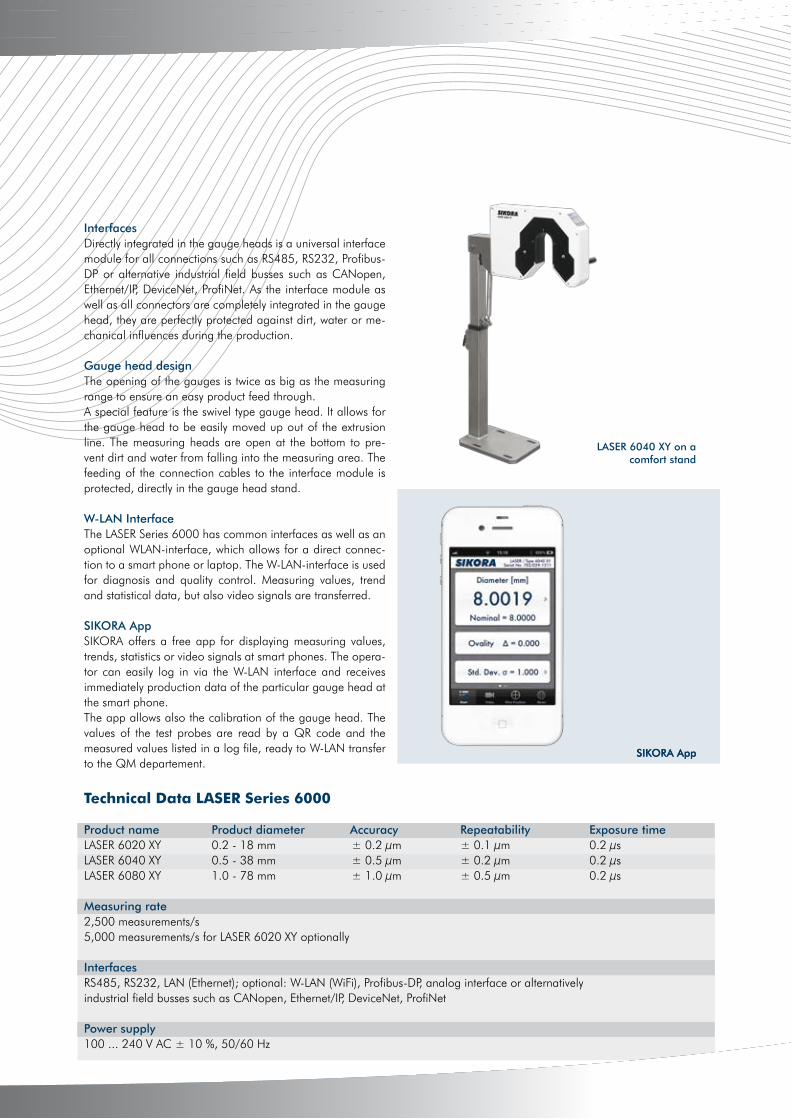
InterfacesDirectly integrated in the gauge heads is a universal interface module for all connections such as RS485, RS232, Profibus-DP or alternative industrial field busses such as CANopen, Ethernet/IP, DeviceNet, ProfiNet. As the interface module as well as all connectors are completely integrated in the gauge head, they are perfectly protected against dirt, water or me-chanical influences during the production.
Gauge head designThe opening of the gauges is twice as big as the measuring range to ensure an easy product feed through. A special feature is the swivel type gauge head. It allows for the gauge head to be easily moved up out of the extrusion line. The measuring heads are open at the bottom to pre-vent dirt and water from falling into the measuring area. The feeding of the connection cables to the interface module is protected, directly in the gauge head stand.
W-LAN InterfaceThe LASER Series 6000 has common interfaces as well as an optional WLAN-interface, which allows for a direct connec-tion to a smart phone or laptop. The W-LAN-interface is used for diagnosis and quality control. Measuring values, trend and statistical data, but also video signals are transferred.
SIKORA AppSIKORA offers a free app for displaying measuring values, trends, statistics or video signals at smart phones. The opera-tor can easily log in via the W-LAN interface and receives immediately production data of the particular gauge head at the smart phone.The app allows also the calibration of the gauge head. The values of the test probes are read by a QR code and the measured values listed in a log file, ready to W-LAN transfer to the QM departement.
Technical Data LASER Series 6000
Product name Product diameter Accuracy Repeatability Exposure timeLASER 6020 XY 0.2 - 18 mm ± 0.2 μm ± 0.1 μm 0.2 μsLASER 6040 XY 0.5 - 38 mm ± 0.5 μm ± 0.2 μm 0.2 μsLASER 6080 XY 1.0 - 78 mm ± 1.0 μm ± 0.5 μm 0.2 μs
Measuring rate2,500 measurements/s5,000 measurements/s for LASER 6020 XY optionally
InterfacesRS485, RS232, LAN (Ethernet); optional: W-LAN (WiFi), Profibus-DP, analog interface or alternatively industrial field busses such as CANopen, Ethernet/IP, DeviceNet, ProfiNet
Power supply100 ... 240 V AC ± 10 %, 50/60 Hz
LASER 6040 XY on a comfort stand
4
www.sikora.net
10
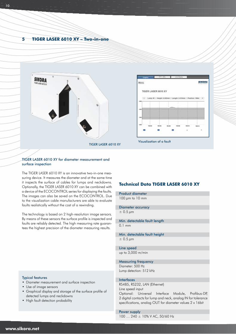
The TIGER LASER 6010 XY is an innovative two-in-one mea-suring device. It measures the diameter and at the same time it inspects the surface of cables for lumps and neckdowns. Optionally, the TIGER LASER 6010 XY can be combined with a device of the ECOCONTROL series for displaying the faults. The images can also be saved on the ECOCONTROL. Due to the visualization cable manufacturers are able to evaluate faults realistically without the cost of a rewinding.
The technology is based on 2 high-resolution image sensors. By means of these sensors the surface profile is inspected and faults are reliably detected. The high measuring rate guaran-tees the highest precision of the diameter measuring results.
TIGER LASER 6010 XY for diameter measurement and surface inspection
5 TIGER LASER 6010 XY – Two-in-one
Technical Data TIGER LASER 6010 XY
Product diameter100 μm to 10 mm
Diameter accuracy± 0.5 μm
Min. detectable fault length0.1 mm
Min. detectable fault height± 0.5 μm
Line speedup to 3,000 m/min
Measuring frequencyDiameter: 500 HzLump detection: 512 kHz
InterfacesRS485, RS232, LAN (Ethernet)Line speed inputOptional: Universal Interface Module, Profibus-DP, 2 digital contacts for lump and neck, analog IN for tolerance specifications, analog OUT for diameter values 2 x 16bit
Power supply100 … 240 ± 10% V AC, 50/60 Hz
Typical features• Diameter measurement and surface inspection• Use of image sensors• Graphical display and storage of the surface profile of detected lumps and neckdowns • High fault detection probability
Visualization of a faultTIGER LASER 6010 XY
5
www.sikora.net
11
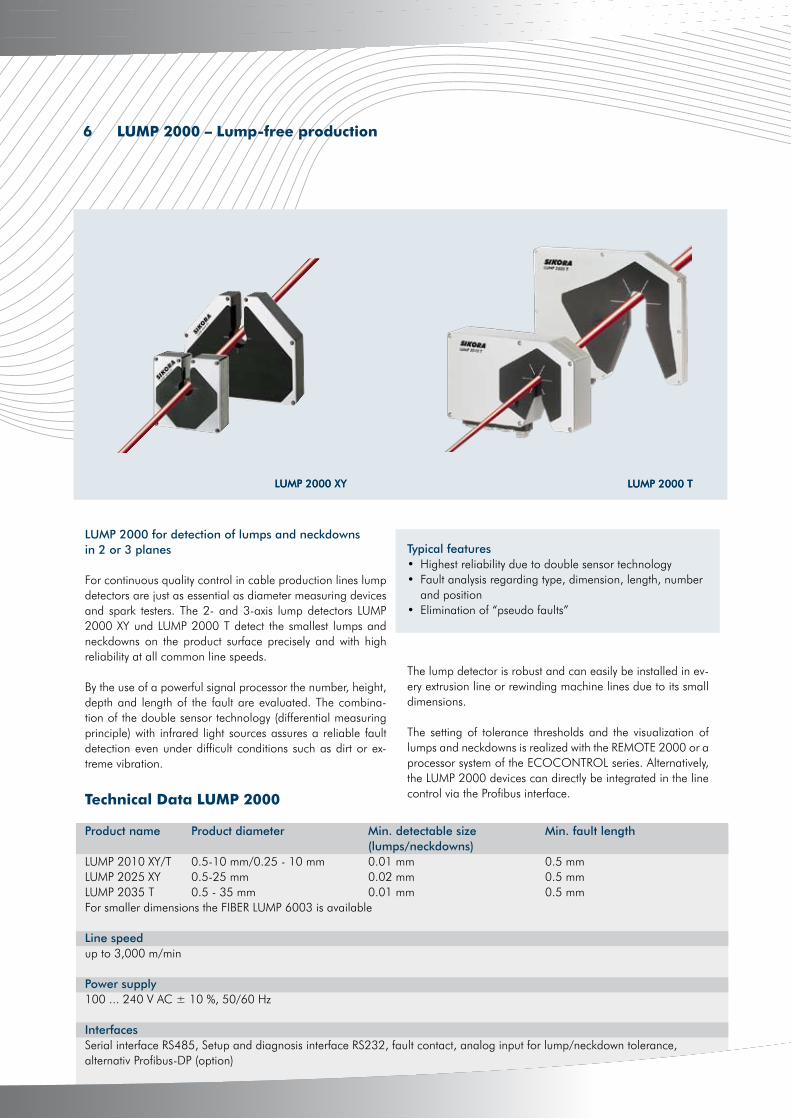
LUMP 2000 XY LUMP 2000 T
6 LUMP 2000 – Lump-free production
LUMP 2000 XY
The lump detector is robust and can easily be installed in ev-ery extrusion line or rewinding machine lines due to its small dimensions.
The setting of tolerance thresholds and the visualization of lumps and neckdowns is realized with the REMOTE 2000 or a processor system of the ECOCONTROL series. Alternatively, the LUMP 2000 devices can directly be integrated in the line control via the Profibus interface.
Typical features• Highest reliability due to double sensor technology• Fault analysis regarding type, dimension, length, number and position• Elimination of “pseudo faults”
For continuous quality control in cable production lines lump detectors are just as essential as diameter measuring devices and spark testers. The 2- and 3-axis lump detectors LUMP 2000 XY und LUMP 2000 T detect the smallest lumps and neckdowns on the product surface precisely and with high reliability at all common line speeds.
By the use of a powerful signal processor the number, height, depth and length of the fault are evaluated. The combina-tion of the double sensor technology (differential measuring principle) with infrared light sources assures a reliable fault detection even under difficult conditions such as dirt or ex-treme vibration.
LUMP 2000 for detection of lumps and neckdowns in 2 or 3 planes
Technical Data LUMP 2000
Product name Product diameter Min. detectable size Min. fault length (lumps/neckdowns)LUMP 2010 XY/T 0.5-10 mm/0.25 - 10 mm 0.01 mm 0.5 mmLUMP 2025 XY 0.5-25 mm 0.02 mm 0.5 mmLUMP 2035 T 0.5 - 35 mm 0.01 mm 0.5 mmFor smaller dimensions the FIBER LUMP 6003 is available
Line speedup to 3,000 m/min
Power supply100 ... 240 V AC ± 10 %, 50/60 Hz
InterfacesSerial interface RS485, Setup and diagnosis interface RS232, fault contact, analog input for lump/neckdown tolerance, alternativ Profibus-DP (option)
LUMP 2000 T
4
www.sikora.net
12
W-LAN (WiFi) ready
At the extrusion of cables their insulation is inspected by sparktesters (high-voltage sparktesters) and possible insula-tion faults are detected and documented at an early stage. For the testing, the dry cable runs through the sturdy elec-trode of the sparktester that is installed after the cooling sec-tion. Here the cable insulation is exposed to the selected test voltage and faults in the insulation are reliably detected. The quality management assures that only faultless cables are delivered.
SIKORA offers for these applications Direct Current (DC), High-Frequency (HF) and Alternating Current (AC) spark testers. The test voltage is continuously adjustable. The spark testers conform to approved test standards (AS, BS, CS, CENELEC, EN, UL, VDE) and safety regulations (as demanded by DIN/VDE 0800, IEC 479-1).
SPARK 2000 DCThe SPARK 2020 DC is a direct-current sparktester, de-signed for the testing of telephone wires, data cables and mini-coax cables with foam insulation, automotive cables and building wires with a diameter from 0.5 to 20 mm.
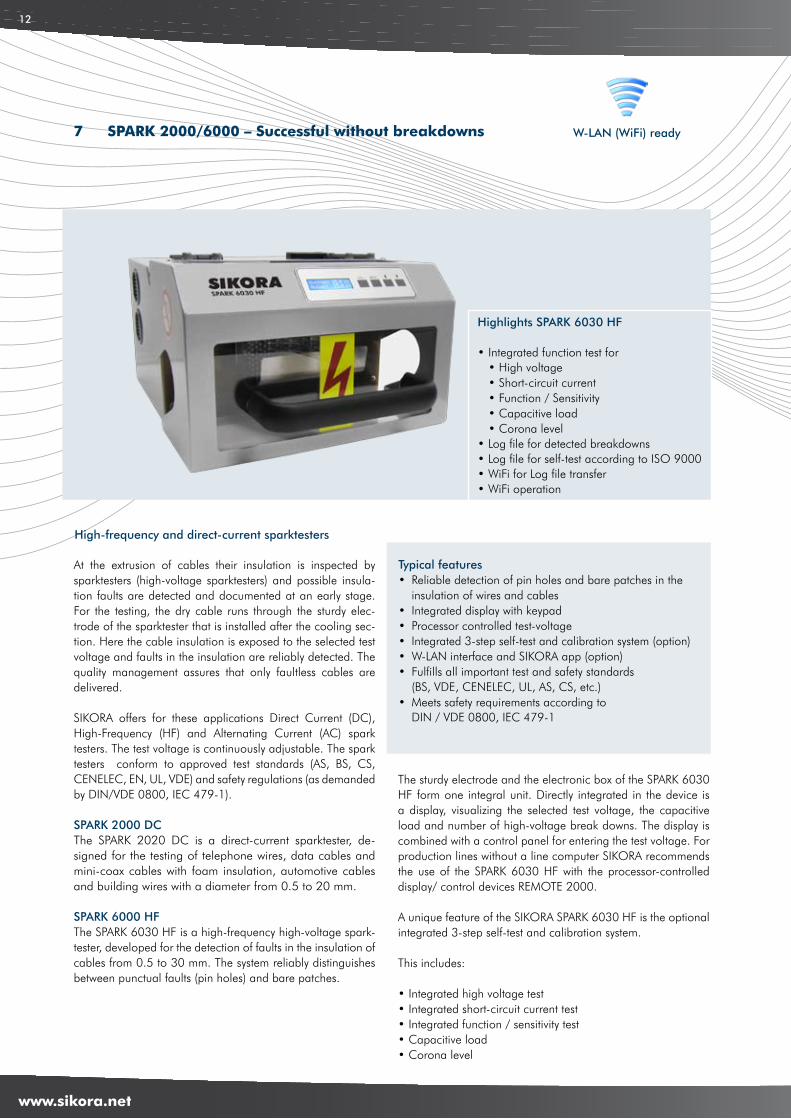
SPARK 6000 HFThe SPARK 6030 HF is a high-frequency high-voltage spark-tester, developed for the detection of faults in the insulation of cables from 0.5 to 30 mm. The system reliably distinguishes between punctual faults (pin holes) and bare patches.
The sturdy electrode and the electronic box of the SPARK 6030 HF form one integral unit. Directly integrated in the device is a display, visualizing the selected test voltage, the capacitive load and number of high-voltage break downs. The display is combined with a control panel for entering the test voltage. For production lines without a line computer SIKORA recommends the use of the SPARK 6030 HF with the processor-controlled display/ control devices REMOTE 2000.
A unique feature of the SIKORA SPARK 6030 HF is the optional integrated 3-step self-test and calibration system.
This includes:
• Integrated high voltage test• Integrated short-circuit current test• Integrated function / sensitivity test• Capacitive load• Corona level
High-frequency and direct-current sparktesters
Typical features• Reliable detection of pin holes and bare patches in the insulation of wires and cables• Integrated display with keypad• Processor controlled test-voltage• Integrated 3-step self-test and calibration system (option)• W-LAN interface and SIKORA app (option)• Fulfills all important test and safety standards (BS, VDE, CENELEC, UL, AS, CS, etc.)• Meets safety requirements according to DIN / VDE 0800, IEC 479-1
7 SPARK 2000/6000 – Successful without breakdowns
Highlights SPARK 6030 HF
• Integrated function test for • High voltage • Short-circuit current • Function / Sensitivity • Capacitive load • Corona level• Log file for detected breakdowns• Log file for self-test according to ISO 9000• WiFi for Log file transfer• WiFi operation

5
www.sikora.net
13
Technical Data SPARK 2000 DC/SPARK 6030 HF
Product name Product diameter Test voltageSPARK 2020 DC 0.5 to 20 mm 0.8 to 7,5 kV DCSPARK 6030 UL 0.5 to 30 mm 0.8 to 15 kVSPARK 6030 HF 0.5 to 30 mm 0.5 to 15 kV
InterfacesRS485, RS232, W-LAN (WiFi) (only at SPARK 6030 HF) (option)Profibus-DP (option)Electrically isolated contactsAnalog in and output test voltage
Power supply100 ... 240 V AC ± 10 %, 50/60 Hz
Innovation: Integrated self-testing and calibration systemAccording to European standards, openly operated mea-suring and testing equipment has to be checked regularly. Accordingly, sparktesters are tested with regard to the high-voltage, short-circuit current and function (sensitivity). While in the past cable manufacturers had to use an external testing device, the SPARK 6030 HF optionally integrates a complete-ly 3-step auto-testing and calibration system. This test is docu-mented, saved in a log-file and can be recalled at any time.
1. Integrated high-voltage testThe sparktester tests the displayed high-voltage of the device for correctness. The high-voltage has to be within a tolerance of 5 %. At the same time the corona level is measured and displayed.
2. Integrated short-circuit current testIn addition to the high-voltage test, the sparktester automati-cally checks the maximum short-circuit current, which at a hu-man body model should not exceed 10 mA when operating the device (according to EN61010-1:2010).
3. Integrated function (sensitivity) testThe sparktester automatically performs a function test (sen-sitivity test). Therefore, 20 artificial faults (breakdowns) are initiated that are detected and reported.
For applications that do not require the integrated display and self-test and calibration system, SIKORA offers the SPARK 2000 UL.
W-LAN interfaceThe SPARK 6030 HF has common interfaces and a W-LAN-interface as an option. Via W-LAN it can be directly connected to a smart phone or Laptop.
SIKORA AppSIKORA offers a free app for diagnosis and quality con-trol at smart phones. The operator can easily log in via the W-LAN interface and immediately receive the number of breakdowns or the high-voltage. With the app, it is also pos-sible to control the high-voltage and to start the self-test. By means of the integrated test function of the SPARK 6030 HF, a detailed test certificate in PDF format is provided within the SIKORA App. This certificate can be transmitted via E-mail to the quality control department.
SIKORA SPARK App
4
www.sikora.net
14
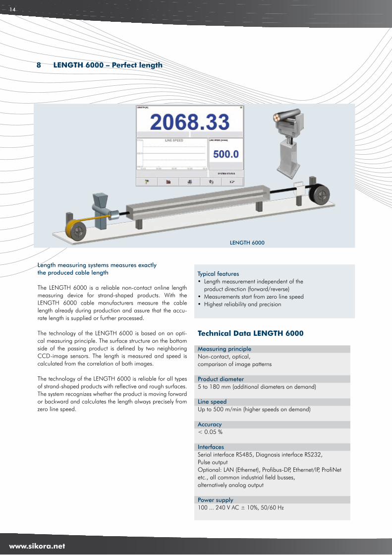
The LENGTH 6000 is a reliable non-contact online length measuring device for strand-shaped products. With the LENGTH 6000 cable manufacturers measure the cable length already during production and assure that the accu-rate length is supplied or further processed.
The technology of the LENGTH 6000 is based on an opti-cal measuring principle. The surface structure on the bottom side of the passing product is defined by two neighboring CCD-image sensors. The length is measured and speed is calculated from the correlation of both images.
The technology of the LENGTH 6000 is reliable for all types of strand-shaped products with reflective and rough surfaces. The system recognizes whether the product is moving forward or backward and calculates the length always precisely from zero line speed.
Typical features• Length measurement independent of the product direction (forward/reverse)• Measurements start from zero line speed• Highest reliability and precision
Length measuring systems measures exactly the produced cable length
LENGTH 6000
Technical Data LENGTH 6000
Measuring principleNon-contact, optical, comparison of image patterns
Product diameter 5 to 180 mm (additional diameters on demand)
Line speedUp to 500 m/min (higher speeds on demand) Accuracy < 0.05 %
Interfaces Serial interface RS485, Diagnosis interface RS232, Pulse outputOptional: LAN (Ethernet), Profibus-DP, Ethernet/IP, ProfiNet etc., all common industrial field busses, alternatively analog output
Power supply 100 ... 240 V AC ± 10%, 50/60 Hz
8 LENGTH 6000 – Perfect length
5
www.sikora.net
15
9 CAPACITANCE 2000 – Superior capacitance measurement thanks to multi-zone technology
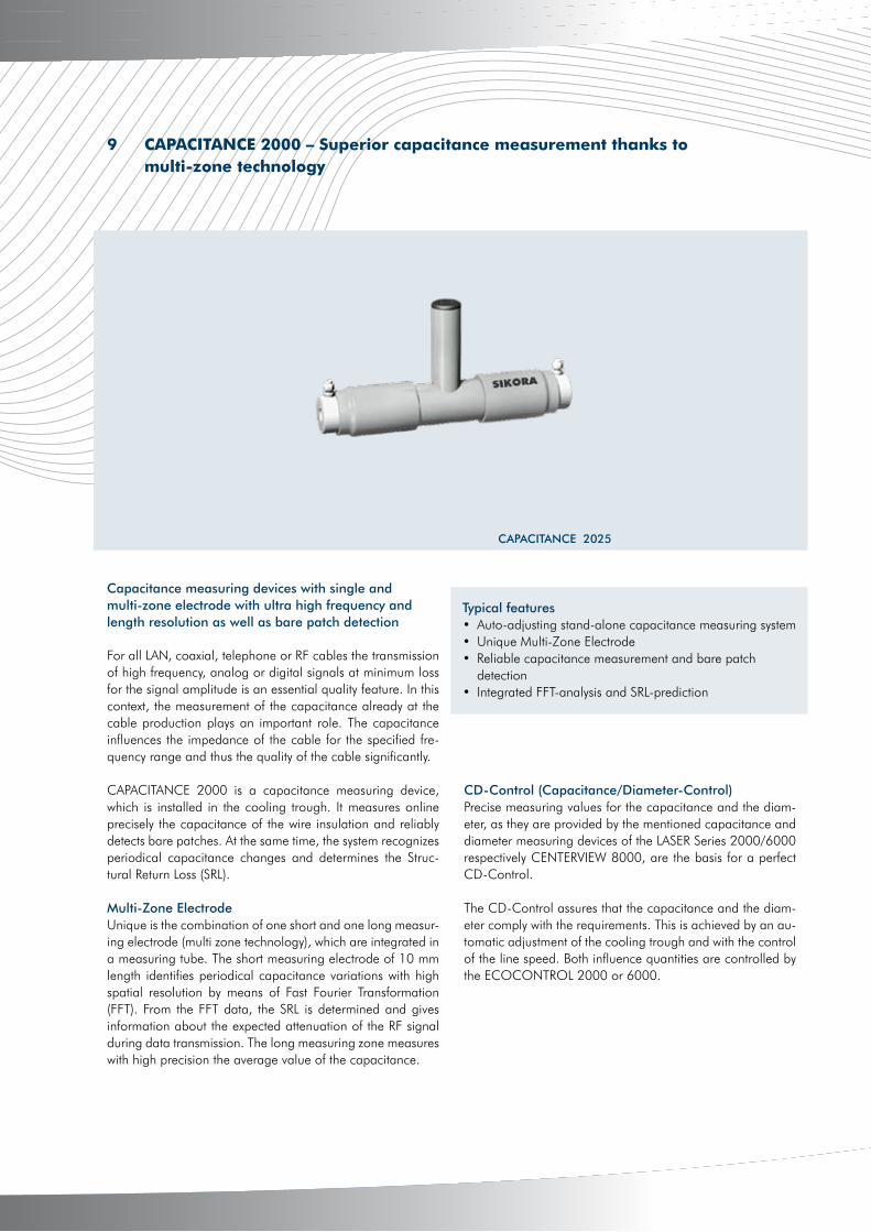
For all LAN, coaxial, telephone or RF cables the transmission of high frequency, analog or digital signals at minimum loss for the signal amplitude is an essential quality feature. In this context, the measurement of the capacitance already at the cable production plays an important role. The capacitance influences the impedance of the cable for the specified fre-quency range and thus the quality of the cable significantly.
CAPACITANCE 2000 is a capacitance measuring device, which is installed in the cooling trough. It measures online precisely the capacitance of the wire insulation and reliably detects bare patches. At the same time, the system recognizes periodical capacitance changes and determines the Struc-tural Return Loss (SRL).
Multi-Zone ElectrodeUnique is the combination of one short and one long measur-ing electrode (multi zone technology), which are integrated in a measuring tube. The short measuring electrode of 10 mm length identifies periodical capacitance variations with high spatial resolution by means of Fast Fourier Transformation (FFT). From the FFT data, the SRL is determined and gives information about the expected attenuation of the RF signal during data transmission. The long measuring zone measures with high precision the average value of the capacitance.
Typical features• Auto-adjusting stand-alone capacitance measuring system• Unique Multi-Zone Electrode• Reliable capacitance measurement and bare patch detection• Integrated FFT-analysis and SRL-prediction
Capacitance measuring devices with single and multi-zone electrode with ultra high frequency and length resolution as well as bare patch detection
CAPACITANCE 2025
CD-Control (Capacitance/Diameter-Control)Precise measuring values for the capacitance and the diam-eter, as they are provided by the mentioned capacitance and diameter measuring devices of the LASER Series 2000/6000 respectively CENTERVIEW 8000, are the basis for a perfect CD-Control.
The CD-Control assures that the capacitance and the diam-eter comply with the requirements. This is achieved by an au-tomatic adjustment of the cooling trough and with the control of the line speed. Both influence quantities are controlled by the ECOCONTROL 2000 or 6000.
4
www.sikora.net
16
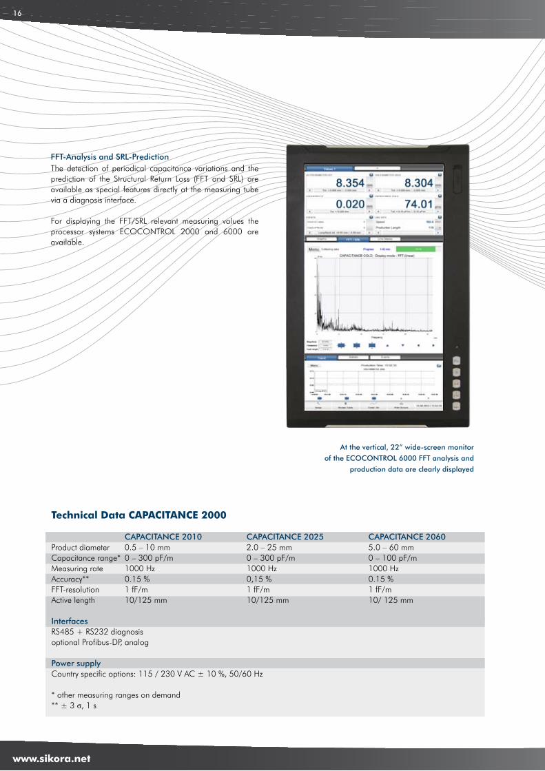
The detection of periodical capacitance variations and the prediction of the Structural Return Loss (FFT and SRL) are available as special features directly at the measuring tube via a diagnosis interface.
For displaying the FFT/SRL relevant measuring values the processor systems ECOCONTROL 2000 and 6000 are available.
FFT-Analysis and SRL-Prediction
Technical Data CAPACITANCE 2000
CAPACITANCE 2010 CAPACITANCE 2025 CAPACITANCE 2060Product diameter 0.5 – 10 mm 2.0 – 25 mm 5.0 – 60 mmCapacitance range* 0 – 300 pF/m 0 – 300 pF/m 0 – 100 pF/mMeasuring rate 1000 Hz 1000 Hz 1000 HzAccuracy** 0.15 % 0,15 % 0.15 %FFT-resolution 1 fF/m 1 fF/m 1 fF/mActive length 10/125 mm 10/125 mm 10/ 125 mm
InterfacesRS485 + RS232 diagnosisoptional Profibus-DP, analog
Power supplyCountry specific options: 115 / 230 V AC ± 10 %, 50/60 Hz
* other measuring ranges on demand ** ± 3 σ, 1 s
At the vertical, 22” wide-screen monitor
of the ECOCONTROL 6000 FFT analysis and
production data are clearly displayed
5
www.sikora.net
17
10 X-RAY 6000 PRO/BASIC – Intelligent partner at the production of cables
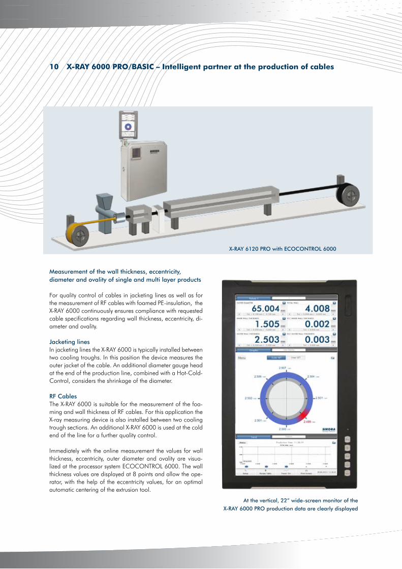
Measurement of the wall thickness, eccentricity, diameter and ovality of single and multi layer products
For quality control of cables in jacketing lines as well as for the measurement of RF cables with foamed PE-insulation, the X-RAY 6000 continuously ensures compliance with requested cable specifications regarding wall thickness, eccentricity, di-ameter and ovality.
Jacketing linesIn jacketing lines the X-RAY 6000 is typically installed between two cooling troughs. In this position the device measures the outer jacket of the cable. An additional diameter gauge head at the end of the production line, combined with a Hot-Cold-Control, considers the shrinkage of the diameter.
RF CablesThe X-RAY 6000 is suitable for the measurement of the foa-ming and wall thickness of RF cables. For this application the X-ray measuring device is also installed between two cooling trough sections. An additional X-RAY 6000 is used at the cold end of the line for a further quality control.
Immediately with the online measurement the values for wall thickness, eccentricity, outer diameter and ovality are visua-lized at the processor system ECOCONTROL 6000. The wall thickness values are displayed at 8 points and allow the ope-rator, with the help of the eccentricity values, for an optimal automatic centering of the extrusion tool.
X-RAY 6120 PRO with ECOCONTROL 6000
At the vertical, 22” wide-screen monitor of the
X-RAY 6000 PRO production data are clearly displayed
4
www.sikora.net
18
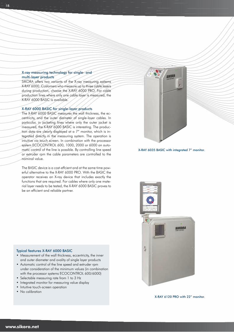
X-ray measuring technology for single- and multi-layer productsSIKORA offers two variants of the X-ray measuring systems X-RAY 6000. Customers who measure up to three cable layers during production, choose the X-RAY 6000 PRO. For cable production lines where only one cable layer is measured, theX-RAY 6000 BASIC is available.
X-RAY 6000 BASIC for single-layer productsThe X-RAY 6000 BASIC measures the wall thickness, the ec-centricity, and the outer diameter of single-layer cables. In particular, in jacketing lines where only the outer jacket is measured, the X-RAY 6000 BASIC is interesting. The produc-tion data are clearly displayed at a 7“ monitor, which is in-tegrated directly in the measuring system. The operation is intuitive via touch screen. In combination with the processor system ECOCONTROL 600, 1000, 2000 or 6000 an auto-matic control of the line is possible. By controlling line speed or extruder rpm the cable parameters are controlled to the nominal value.
The BASIC device is a cost-effcient and at the same time pow-erful alternative to the X-RAY 6000 PRO. With the BASIC the operator receives an X-ray device that includes exactly the functions that are required. For cables where only one mate-rial layer needs to be tested, the X-RAY 6000 BASIC proves to be an efficient and reliable partner.
X-RAY 6035 BASIC with integrated 7” monitor.
Typical features X-RAY 6000 BASIC• Measurement of the wall thickness, eccentricity, the inner and outer diameter and ovality of single layer products • Automatic control of the line speed and extruder rpm under consideration of the minimum values (in combination with the processor systems ECOCONTROL 600/6000)• Selectable measuring rate from 1 to 3 Hz • Integrated monitor for measuring value display • Intuitive touch-screen operation• No calibration
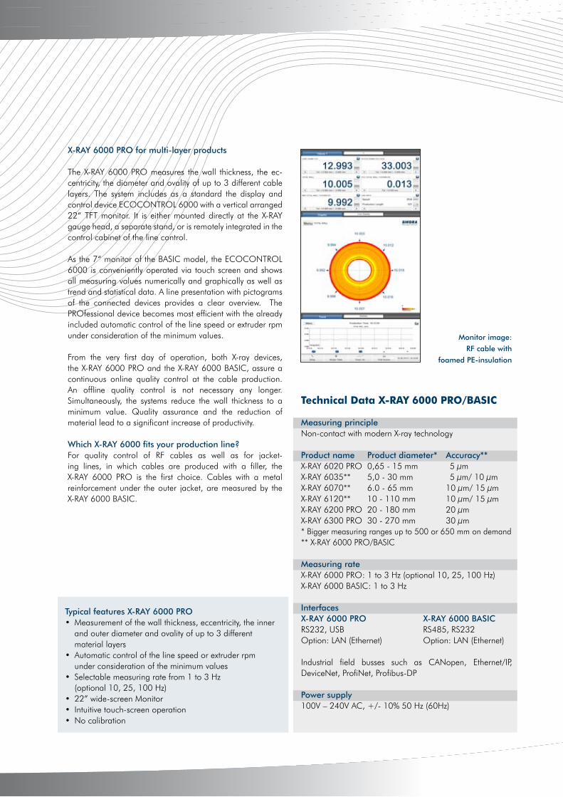
X-RAY 6120 PRO with 22” monitor.
5
www.sikora.net
19
Technical Data X-RAY 6000 PRO/BASIC
Measuring principleNon-contact with modern X-ray technology
Product name Product diameter* Accuracy** X-RAY 6020 PRO 0,65 - 15 mm 5 μmX-RAY 6035** 5,0 - 30 mm 5 μm/ 10 μmX-RAY 6070** 6.0 - 65 mm 10 μm/ 15 μmX-RAY 6120** 10 - 110 mm 10 μm/ 15 μmX-RAY 6200 PRO 20 - 180 mm 20 μmX-RAY 6300 PRO 30 - 270 mm 30 μm* Bigger measuring ranges up to 500 or 650 mm on demand** X-RAY 6000 PRO/BASIC
Measuring rateX-RAY 6000 PRO: 1 to 3 Hz (optional 10, 25, 100 Hz)X-RAY 6000 BASIC: 1 to 3 Hz InterfacesX-RAY 6000 PRO X-RAY 6000 BASICRS232, USB RS485, RS232Option: LAN (Ethernet) Option: LAN (Ethernet) Industrial field busses such as CANopen, Ethernet/IP, DeviceNet, ProfiNet, Profibus-DP
Power supply100V – 240V AC, +/- 10% 50 Hz (60Hz)
Typical features X-RAY 6000 PRO• Measurement of the wall thickness, eccentricity, the inner and outer diameter and ovality of up to 3 different material layers • Automatic control of the line speed or extruder rpm under consideration of the minimum values• Selectable measuring rate from 1 to 3 Hz (optional 10, 25, 100 Hz)• 22” wide-screen Monitor• Intuitive touch-screen operation• No calibration
X-RAY 6000 PRO for multi-layer products
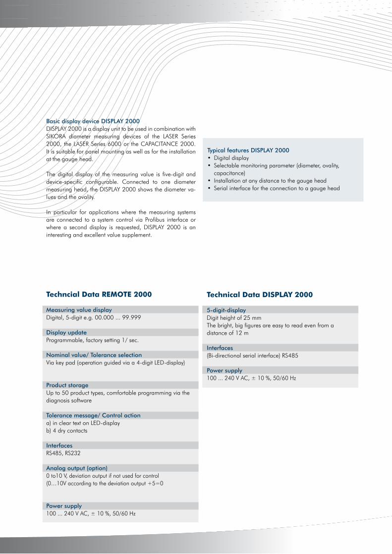
The X-RAY 6000 PRO measures the wall thickness, the ec-centricity, the diameter and ovality of up to 3 different cable layers. The system includes as a standard the display and control device ECOCONTROL 6000 with a vertical arranged 22“ TFT monitor. It is either mounted directly at the X-RAY gauge head, a separate stand, or is remotely integrated in the control cabinet of the line control.
As the 7“ monitor of the BASIC model, the ECOCONTROL 6000 is conveniently operated via touch screen and shows all measuring values numerically and graphically as well as trend and statistical data. A line presentation with pictograms of the connected devices provides a clear overview. The PROfessional device becomes most efficient with the already included automatic control of the line speed or extruder rpm under consideration of the minimum values.
From the very first day of operation, both X-ray devices, the X-RAY 6000 PRO and the X-RAY 6000 BASIC, assure a continuous online quality control at the cable production. An offline quality control is not necessary any longer. Simultaneously, the systems reduce the wall thickness to a minimum value. Quality assurance and the reduction of material lead to a significant increase of productivity.
Which X-RAY 6000 fits your production line?For quality control of RF cables as well as for jacket-ing lines, in which cables are produced with a filler, the X-RAY 6000 PRO is the first choice. Cables with a metal reinforcement under the outer jacket, are measured by the X-RAY 6000 BASIC.
Monitor image:
RF cable with
foamed PE-insulation

4
www.sikora.net
20
In addition to the innovative measuring and testing systems SIKORA offers compatible display and control devices. The REMOTE 2000 is the basic display and control device and universally applicable for all SIKORA diameter measuring de-vices. The display of the measuring values is on a five-digit 20 mm high clear LED display. It is perfectly suitable for panel mounting or for building on the gauge head.
LASER Series 2000/6000 in combination with theREMOTE 2000The REMOTE 2000 can be combined with a diameter gauge head of the LASER Series 2000 or LASER Series 6000. The average diameter value of the connected measuring device is clearly displayed at the LED display. Via a control key the average diameter value or the display of the ovality can be selected.
The REMOTE 2000 includes a product library for up to 50 cable recipes. Nominal values and tolerances can easily be recalled. In combination with the control module SET POINT an automatic control of the line speed or extruder rpm during the production is ensured. Optionally, a length-related print out of the measuring values as well as statistical data are available.
Furthermore, the REMOTE 2000 provides an interface, to support a connection to an external PC for data gathering or PLC line control operations. In this way a targeted and direct control is assured.
SPARK 2000/6000 in combination with theREMOTE 2000For use with the SPARK 2000/6000 for the detection of insula-tion breakdowns, the REMOTE 2000 is also suitable. Parame-ters such as the nominal testing voltage can be entered easily. User-friendly symbols and numeric displays clearly show the current testing voltage and the number of breakdowns.
LUMP 2000 in combination with the REMOTE 2000In combination with a LUMP 2000, the REMOTE 2000 shows the number as well as the type of faults. Different symbols in-form the operator if the fault is a lump or neckdown. Lump or neckdown information such as the height, depth and length of the fault are stored, giving the operator the possibility to view previous faults.
CAPACITANCE 2000 in combination with theREMOTE 2000In combination with the capacitance measuring device CAPACITANCE 2000 the REMOTE 2000 clearly presents the capacitance measuring values as a decentralized display device.
Typical features REMOTE 2000 • Large, clearly arranged display and keypad• Easy building at any distance to the measuring head• Automatic control module SET POINT (optional)• Serial interface for the connection to a measuring head, a computer and a protocol printer (optional)
11 REMOTE/DISPLAY 2000 – Visualisierung und Regelung der Produktionsdaten
DISPLAY 2000REMOTE 2000
5
www.sikora.net
21
Techncial Data REMOTE 2000
Measuring value display Digital, 5-digit e.g. 00.000 ... 99.999
Display update Programmable, factory setting 1/ sec.
Nominal value/ Tolerance selection Via key pad (operation guided via a 4-digit LED-display)
Product storage Up to 50 product types, comfortable programming via thediagnosis software
Tolerance message/ Control action a) in clear text on LED-displayb) 4 dry contacts
Interfaces RS485, RS232
Analog output (option) 0 to10 V, deviation output if not used for control(0…10V according to the deviation output +5=0
Power supply 100 ... 240 V AC, ± 10 %, 50/60 Hz
Basic display device DISPLAY 2000DISPLAY 2000 is a display unit to be used in combination with SIKORA diameter measuring devices of the LASER Series 2000, the LASER Series 6000 or the CAPACITANCE 2000. It is suitable for panel mounting as well as for the installation at the gauge head.
The digital display of the measuring value is five-digit and device-specific configurable. Connected to one diameter measuring head, the DISPLAY 2000 shows the diameter va-lues and the ovality.
In particular for applications where the measuring systems are connected to a system control via Profibus interface or where a second display is requested, DISPLAY 2000 is an interesting and excellent value supplement.
Technical Data DISPLAY 2000
5-digit-display Digit height of 25 mmThe bright, big figures are easy to read even from adistance of 12 m
Interfaces (Bi-directional serial interface) RS485
Power supply 100 ... 240 V AC, ± 10 %, 50/60 Hz
Typical features DISPLAY 2000 • Digital display • Selectable monitoring parameter (diameter, ovality, capacitance)• Installation at any distance to the gauge head• Serial interface for the connection to a gauge head
4
www.sikora.net
22
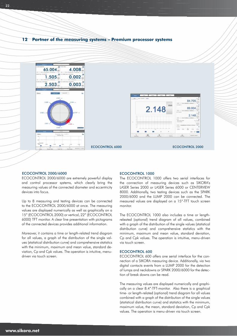
ECOCONTROL 6000 ECOCONTROL 2000
ECOCONTROL 2000/6000 are extremely powerful display and control processor systems, which clearly bring the measuring values of the connected diameter and eccentricity devices into focus.
Up to 8 measuring and testing devices can be connected to the ECOCONTROL 2000/6000 at once. The measuring values are displayed numerically as well as graphically on a 15” (ECOCONTROL 2000) or vertical, 22” (ECOCONTROL 6000) TFT monitor. A clear line presentation with pictograms of the connected devices provides additional information.
Moreover, it contains a time or length-related trend diagram for all values, a graph of the distribution of the single val-ues (statistical distribution curve) and comprehensive statistics with the minimum, maximum and mean value, standard de-viation, Cp and Cpk values. The operation is intuitive, menu-driven via touch screen.
ECOCONTROL 2000/6000 ECOCONTROL 1000The ECOCONTROL 1000 offers two serial interfaces for the connection of measuring devices such as SIKORA’s LASER Series 2000 or LASER Series 6000 or CENTERVIEW 8000. Additionally, two testing devices such as the SPARK 2000/6000 and the LUMP 2000 can be connected. The measured values are displayed on a 15“-TFT touch screen monitor.
The ECOCONTROL 1000 also includes a time or length-releated (optional) trend diagram of all values, combined with a graph of the distribution of the single values (statistical distribution curve) and comprehensive statistics with the minimum, maximum and mean value, standard deviation, Cp and Cpk values. The operation is intuitive, menu-driven via touch screen.
ECOCONTROL 600ECOCONTROL 600 offers one serial interface for the con-nection of a SIKORA measuring device. Additionally, via two digital contacts events from a LUMP 2000 for the detection of lumps and neckdowns or SPARK 2000/6000 for the detec-tion of break downs can be read.
The measuring values are displayed numerically and graphi-cally on a clear 8.4”-TFT-monitor. Also there is a graphical time- or length-related (optional) trend diagram for all values combined with a graph of the distribution of the single values (statistical distribution curve) and statistics with the minimum, maximum value, the mean, standard deviation, Cp and Cpk values. The operation is menu-driven via touch screen.
12 Partner of the measuring systems – Premium processor systems
5
www.sikora.net
23
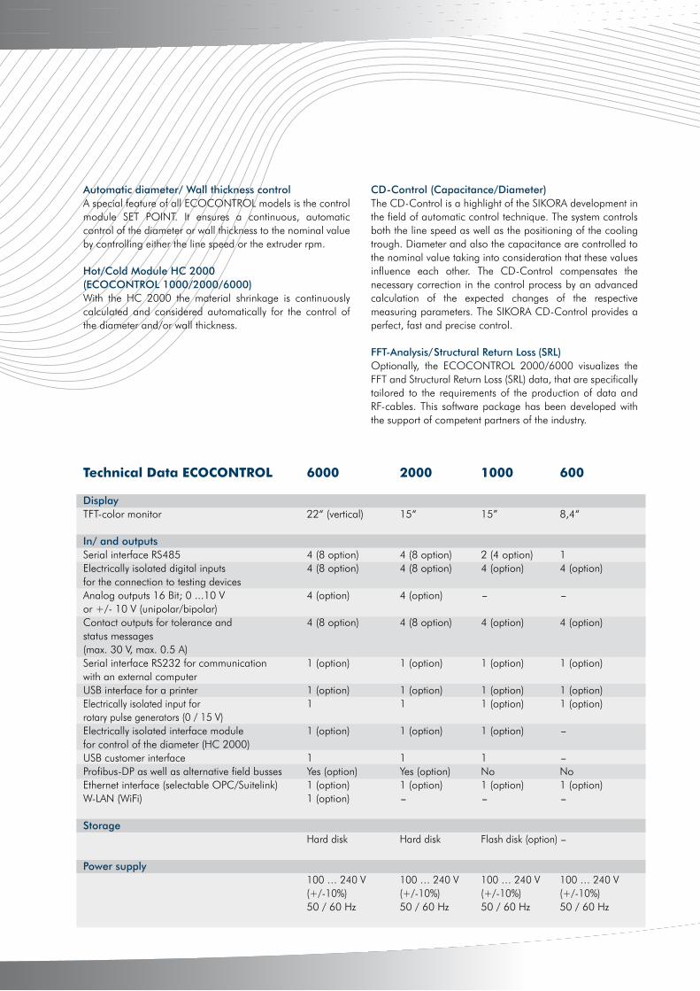
Technical Data ECOCONTROL 6000 2000 1000 600
Display TFT-color monitor 22“ (vertical) 15“ 15” 8,4“
In/ and outputsSerial interface RS485 4 (8 option) 4 (8 option) 2 (4 option) 1Electrically isolated digital inputs 4 (8 option) 4 (8 option) 4 (option) 4 (option)for the connection to testing devices Analog outputs 16 Bit; 0 ...10 V 4 (option) 4 (option) - -or +/- 10 V (unipolar/bipolar)Contact outputs for tolerance and 4 (8 option) 4 (8 option) 4 (option) 4 (option)status messages (max. 30 V, max. 0.5 A) Serial interface RS232 for communication 1 (option) 1 (option) 1 (option) 1 (option)with an external computerUSB interface for a printer 1 (option) 1 (option) 1 (option) 1 (option)Electrically isolated input for 1 1 1 (option) 1 (option)rotary pulse generators (0 / 15 V) Electrically isolated interface module 1 (option) 1 (option) 1 (option) -for control of the diameter (HC 2000)USB customer interface 1 1 1 -Profibus-DP as well as alternative field busses Yes (option) Yes (option) No NoEthernet interface (selectable OPC/Suitelink) 1 (option) 1 (option) 1 (option) 1 (option)W-LAN (WiFi) 1 (option) - - -
Storage Hard disk Hard disk Flash disk (option) -
Power supply 100 … 240 V 100 … 240 V 100 … 240 V 100 … 240 V (+/-10%) (+/-10%) (+/-10%) (+/-10%) 50 / 60 Hz 50 / 60 Hz 50 / 60 Hz 50 / 60 Hz
Automatic diameter/ Wall thickness controlA special feature of all ECOCONTROL models is the control module SET POINT. It ensures a continuous, automatic control of the diameter or wall thickness to the nominal value by controlling either the line speed or the extruder rpm.
Hot/Cold Module HC 2000 (ECOCONTROL 1000/2000/6000)With the HC 2000 the material shrinkage is continuously calculated and considered automatically for the control of the diameter and/or wall thickness.
CD-Control (Capacitance/Diameter)The CD-Control is a highlight of the SIKORA development in the field of automatic control technique. The system controls both the line speed as well as the positioning of the cooling trough. Diameter and also the capacitance are controlled to the nominal value taking into consideration that these values influence each other. The CD-Control compensates the necessary correction in the control process by an advanced calculation of the expected changes of the respective measuring parameters. The SIKORA CD-Control provides a perfect, fast and precise control.
FFT-Analysis/Structural Return Loss (SRL)Optionally, the ECOCONTROL 2000/6000 visualizes the FFT and Structural Return Loss (SRL) data, that are specifically tailored to the requirements of the production of data and RF-cables. This software package has been developed with the support of competent partners of the industry.

4
www.sikora.net
24
The virtual gauge technology is suitable for all applications, where a fast wall thickness control is required, but where due to the line configuration or the product structure a diameter or wall thickness measurement directly after the extruder is not possible. Reasons could be a lack of space for a hot di-ameter gauge head or the need for an immediate cooling of the product after the extrusion.
In these cases the intelligent software concept VIRTUAL 2000 is the solution: the measuring device is installed at the end of the cooling trough section. Up to now, the control of the ex-truder at the end of the line was very slow. The reason was the big delay time, a result of the low line speeds and the big dis-tance between the measuring device and the extruder cross-head. This delay time is eliminated by the VIRTUAL 2000.
Already at the start-up of the line an extruder model of the VIRTUAL 2000 calculates the expected cold wall thickness for a defined core diameter and a predefined material depend-ing on the specified extruder rpm and the line speed. The VIRTUAL 2000 displays the cold wall thickness even before the product reaches the measuring system at the end of the line. Already during the start-up process the VIRTUAL 2000 controls the required extruder rpm, in order to achieve the cold wall thickness, set by the operator. The control and the regulation of the extruder is done under consideration of the line speed, selected by the operator. There is no need for any shrinkage setting.
VIRTUAL 2000 - Intelligent software concept
Monitor image ECOCONTROL 6000
Monitor image ECOCONTROL 2000 Monitor image ECOCONTROL 600
Monitor image FFT

5
www.sikora.net
25

www.sikora.net
ISO 9001
QUALITY
SIKORA KG/H
B/D
H/5
00/0
8/12
Technical data is subject to change
We are here for you!SIKORA AGHeadquartersBruchweide 228307 BremenGermanyPh: +49 421 48900 [email protected]
UNITED ARAB [email protected]