measurement data wireless communication systemecatalog.mitutoyo.com/cmimages/003/313/uwave.pdf ·...
TRANSCRIPT
A-14
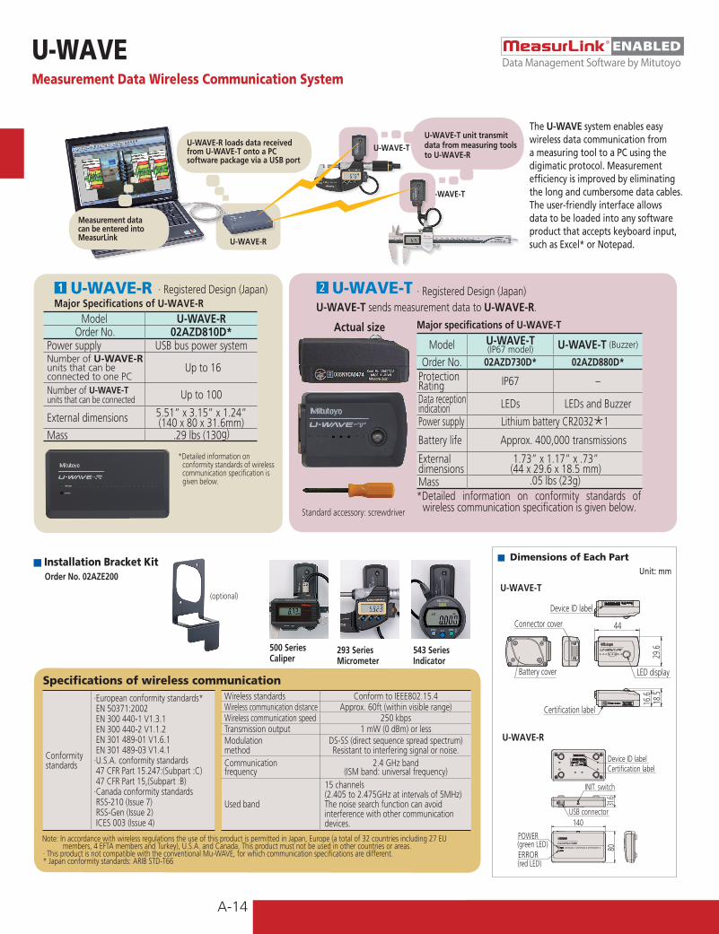
■ Dimensions of Each PartUnit: mm
(red LED)ERROR(green LED)POWER
USB connector
INIT. switch
Certification labelDevice ID label
140
31.6
80
LED display
Certification label
Device ID label
Connector cover
Battery cover
18.5
16.6
44
29.6
U-WAVE-R
U-WAVE-T
The U-WAVE system enables easy wireless data communication from a measuring tool to a PC using the digimatic protocol. Measurement efficiency is improved by eliminating the long and cumbersome data cables. The user-friendly interface allows data to be loaded into any software product that accepts keyboard input, such as Excel* or Notepad.U-WAVE-R
U-WAVE-R loads data received from U-WAVE-T onto a PC software package via a USB port
Measurement data can be entered into MeasurLink
U-WAVEMeasurement Data Wireless Communication System
n2 U-WAVE-TU-WAVE-T sends measurement data to U-WAVE-R.
Model U-WAVE-T (IP67 model) U-WAVE-T (Buzzer)
Order No. 02AZD730D* 02AZD880D*Protection Rating IP67 –
Data receptionindication LEDs LEDs and Buzzer
Power supply Lithium battery CR2032Õ1
Battery life Approx. 400,000 transmissions
Externaldimensions
1.73” x 1.17” x .73” (44 x 29.6 x 18.5 mm)
Mass .05 lbs (23g)
Major specifications of U-WAVE-TActual size
· Registered Design (Japan)
*Detailed information on conformity standards of wireless communication specification is given below.
· Registered Design (Japan)n1 U-WAVE-RMajor Specifications of U-WAVE-R
*Detailed information on conformity standards of wireless communication specification is given below.
Standard accessory: screwdriver
Model U-WAVE-ROrder No. 02AZD810D*
Power supply USB bus power systemNumber of U-WAVE-R units that can beconnected to one PC
Up to 16
Number of U-WAVE-Tunits that can be connected Up to 100
External dimensions 5.51” x 3.15” x 1.24” (140 x 80 x 31.6mm)
Mass .29 lbs (130g)
Conformity standards
·European conformity standards* EN 50371:2002 EN 300 440-1 V1.3.1 EN 300 440-2 V1.1.2 EN 301 489-01 V1.6.1 EN 301 489-03 V1.4.1·U.S.A. conformity standards 47 CFR Part 15.247:(Subpart :C) 47 CFR Part 15,(Subpart :B)·Canada conformity standards RSS-210 (Issue 7) RSS-Gen (Issue 2) ICES 003 (Issue 4)
Wireless standards Conform to IEEE802.15.4Wireless communication distance Approx. 60ft (within visible range)Wireless communication speed 250 kbpsTransmission output 1 mW (0 dBm) or lessModulation method
DS-SS (direct sequence spread spectrum)Resistant to interfering signal or noise.
Communicationfrequency
2.4 GHz band (ISM band: universal frequency)
Used band
15 channels (2.405 to 2.475GHz at intervals of 5MHz)The noise search function can avoid interference with other communication devices.
Specifications of wireless communication
Note: In accordance with wireless regulations the use of this product is permitted in Japan, Europe (a total of 32 countries including 27 EU members, 4 EFTA members and Turkey), U.S.A. and Canada. This product must not be used in other countries or areas.
· This product is not compatible with the conventional Mu-WAVE, for which communication specifications are different.* Japan conformity standards: ARIB STD-T66
■ Installation Bracket KitOrder No. 02AZE200
(optional)
500 SeriesCaliper
293 SeriesMicrometer
543 SeriesIndicator
U-WAVE-TU-WAVE-T unit transmit data from measuring tools to U-WAVE-R
Data Management Software by MitutoyoENABLED
Cautions · Safety caution: Do not use this device near medical equipment that might
malfunction due to radio interference.· Caution on radio law: This device is certified as a 2.4 GHz band wide-band low-
power data communication system based on the radio regulations in Japan, Europe, U.S.A. and Canada.
It is prohibited by law to disassemble or modify this device or peel off the certification label from it.

A-15
ENABLED
■List of U-WAVE-T Connecting CablesFrom seven types of cables (A to G ), select one compatible with your measuring tool.
Cautions · Safety caution: Do not use this device near medical equipment that might
malfunction due to radio interference.· Caution on radio law: This device is certified as a 2.4 GHz band wide-band low-
power data communication system based on the radio regulations in Japan, Europe, U.S.A. and Canada.
It is prohibited by law to disassemble or modify this device or peel off the certification label from it.
■Note on Wireless Communication EnvironmentAlthough the communication range for U-WAVE is approximately 60 ft. line-of-sight, performance may be affected by obstacles or environmental factors.
Item Contents
Concrete wall Communication is not possible in a completely enclosed room.
Metal partition Communication speed may drop or communication may be interrupted.
Wireless LAN, communication device such as ZigBee Bluetooth, and microwave oven
Communication speed may drop or communication may be interrupted. Maintain the set frequency and installation distance if at all possible.
Medical instrument Do not use this product near a medical instrument such as a laser knife or electronic scale.
Items that may cause communication errors
160
Fasten the connector to U-WAVE-T with two screws.
U-WAVE-TMeasuring toolSelect one from cables A to G, referring to the part number of connecting cable for wired connection in your measuring tool catalog or manual. If you are unsure which cable is appropriate, check the cable connectors, the shapes of terminal on the measuring tool side, or the codes of compatible measuring tool for cables A to G below.It is not possible to connect to EF and EH counters.
U-WAVEMeasurement Data Wireless Communication System
Cable type AWater-proof model with output button B Water-proof model
with output button CWith data-out button type D10-pin plain type E 6-pin round F Plain type straight G Plain type straight
water-proof model
Connector shapeon the measuringtool side
Socket shape on the measuring tool
[Digimatic Caliper] [Digimatic Micrometer] [Digimatic Caliper] [Digimatic Indicator] [Digimatic Micrometer] [Digimatic Caliper] [Digimatic Indicator]CD67-S_PM MDE-MJ CD-CX/-C ID-H/F MDQ-M CD, CFC-P/-L/-C/-U ID-NCD-PMX MDC-MJ/MJT CD-S_C [Linear Height] MDC-M [Digimatic Height Gages] ID-BCD-PM/GM [Digimatic Micrometer] CDC-CX/C QMH-S CLM1-QM/DK HD-AX, HDM-AXCDC-P_PMX The code suffix is -MJ. CDN-CX/C [Linear Gage/Counter] PDM-QM HDS-H_C/-C
Codes of major compatible measuring tools and instruments
CDN-P_PMX BLM-M [Digimatic Caliper] EB,EC-D PMU-DM HDM-ACFC-G/GL/GC/GU OMV-M NTD-CX/C [μ-checker] BD-M HDF-N[Digimatic Caliper] OMP-M [Digimatic Depth Gage] Digital μ-checker [Digimatic Holtest] [Digimatic Indicator]NTD-PMX PDM-M VDS-DCX [Laser Scan Micrometer] HTD ID-C/_RB/_A/_GB[Digimatic Depth Gage] IMP-M [Digital Scale and LSM-9506 [Reference Gage] ID-S/UVDS-PMX VM-M DRO Systems] [Reference Gage] HDM-DM [Digimatic Depth Gage][Digital Scale and [Digimatic Micrometer Heads] SD-D, SDV-D HDM-C [Hardness Testing Machines] Digimatic model (ID-C) DRO Systems] MHN-M/MJ/MJN [Coating Thickness Gage] HM-100/200 [Digital Scale and SD-G [Digimatic Holtest] DGE-745/755 HV-100 DRO Systems]
HTD-R [Form Measurement] HR-500 SD-E, SDV-E[Digimatic Depth Gage] SJ-201/301/401 HH-411 SD-F, SDV-FDMC-M [Portable Hardness
Testing Instruments]HH-300
Light gray Light gray
Reference Order No. of connecting cable
1m 05CZA624 05CZA662 959149 936937 937387 905338 21EAA1942m 05CZA625 05CZA663 959150 965014 965013 905409 21EAA190
When connected with U-WAVE-T Select one of the USB input tool direct from table below to fit the connector (A to G) and also select either standard type (fig.1) or foot switch type (fig.2) dependent on usage. Note: Not connectable to these Mitutoyo products: Litematic VL, Linear Gage Counter EF/EH, Surftest SJ-500.
DATA
Fig.2 Connecting cable for foot switch
DATA
Fig.1 Standard type connecting cable
For standard Order No. 02AZD790A 02AZD790B 02AZD790C 02AZD790D 02AZD790E 02AZD790F 02AZD790GFor foot switch
Order No. 02AZE140A 02AZE140B 02AZE140C 02AZE140D 02AZE140E 02AZE140F 02AZE140G
A B C D E F G
Data Management Software by MitutoyoENABLED