measure • monitor • control - wdm, inc.wdminc.com/images/uptimedevices.pdf · the remote power...
TRANSCRIPT

WDM INCwww.wdminc.com
Measure • Monitor • Control
© Uptime Devices

Measure • Monitor • Control
What We Do• We provide network appliances and other mission critical network infrastructure (both hardware and software solutions) for network management and remote monitoring and control applications. Specific areas of focus by Uptime Devices include environmental, security, and power.
• In today’s mission critical networks many things can affect availability. Software issues, Hardware issues, even things not on the Network leave you vulnerable to costly failures. Uptime Devices completes your protective portfolio by network and web enabling previously unreachable devices, giving you the ability to head problems off before they happen and giving you the freedom to manage your network on your terms.
© Uptime Devices

Measure • Monitor • Control
Clients
• With the largest installed base in the market here is a sampling of some of our satisfied clients:


sensorArray sensorArray Pro sensorArray XP
Measure • Monitor • Control
sensorArray Product Family
•8 external ports standard
•Expandable to 48 ports
•Desktop
•8.5" W x 1.75" H x 4.25"D(215.9mm W x 44.45mm H x 107.95mm D)
•connect up to 6 dry contacts on a port via common ground
•14 external ports standard
•Expandable to 48 ports
•Desktop, 1U Rack mount or 0U Vertical mount
•17" W x 1.75" H x 5" D(431.5mm W x 44.45mm H x 127mm D)
•18 port expansion unit for sensorArray and sensorArray Pro
•Desktop, 1U Rack mount or 0U Vertical mount
•17" W x 1.75" H x 5"D(431.5mmWx44.45mm H x 127mm D

Measure • Monitor • Control
sensorProbe
Features• On board graphing capability • Sends e-mail notifications • External sensor port with auto-sense • Sends SNMP traps to 2 destinations • Supports SNMP polling • 2 levels of password protection • Internal web server • 0 U rack mountable • Fully compliant with all operating systems • Includes easy to read documentation and helpful utilities • Free trial version of OverTime • MIB integrates with all popular NMS
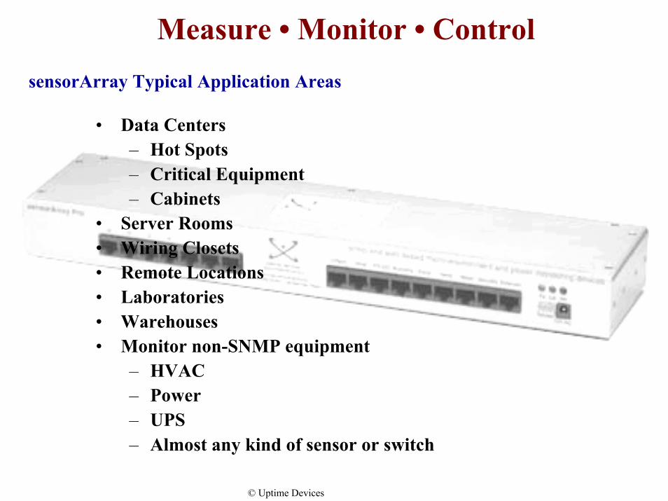
– Hot Spots– Critical Equipment– Cabinets
• Server Rooms• Wiring Closets• Remote Locations• Laboratories• Warehouses• Monitor non-SNMP equipment
• Data Centers
– HVAC– Power– UPS– Almost any kind of sensor or switch
Measure • Monitor • Control
© Uptime Devices
sensorArray Typical Application Areas

Measure • Monitor • Control
© Uptime Devices
sensorArray Typical Application

•Plug and Go Network Appliance
•User Friendly Web Interface
•SNMP Traps
•E-mail Notifications
•IP Settings Security
•NNM MIB
•Quick start installation guides
•Helpful Utilities
•Thorough Documentation Package
Measure • Monitor • Control
© Uptime Devices
sensorArray User Features

Measure • Monitor • Control
Environmental Sensors
• Humidity• Water• Security Contacts• Temperature• Airflow• Motion Detection• In addition to our proprietary line of
environmental sensors, we can support a wide variety of sensors you may have or are planning on installing .(Teach an old sensor new tricks)

Measure • Monitor • Control
HUMIDITY SENSORSDescription
Humidity sensors measure the relative humidity in the air. The sensor is composed of a semiconductor whose capacitance varies with humidity. The small changes in capacitance are converted into a DC voltage by active circuits placed near the sensor. This DC voltage is then transmitted to the sensorArray along a 15 foot cable. The DC voltage is measured by the sensorArray using it A/D converter.
WATER DETECTORS
Description
Water Detectors are active switches that close in the presence of water. The sensorArray senses the closure and reports the condition. Water detectors can be wired in parallel through through use of RJ45 splitters. This way multiple water detectors can use a single port on the sensorArray. There are no reasonable limits on the distance of the water detectors from the sensorArray.
SECURITY SENSORS
Description
Security Sensors come in pairs. They are active switches that close when one half of the sensor is in close proximity to its mate. When the two sensor pairs are moved apart from each other they open. The sensorArraysenses the closure and open and reports the condition. Security Sensors can be wired in series so that multiple sensors can use a single port on the sensorArray. There are no reasonable limits on the distance of the securitysensors from the sensorArray.
External Sensors
© Uptime Devices

Measure • Monitor • ControlExternal SensorsTEMPERATURE SENSORSDescription
Temperature sensors measure the temperature levels in an environment. They have a range of –55 C to 100 C and are accurate to 0.5 C. There are no reasonable limits on the distance of the temperature sensors from the sensorArray.
© Uptime Devices

Measure • Monitor • Control
Switches
• Monitor 32 Inputs• Control 20 Outputs• Open/Closed or Ground/+5V• Uptime Devices helps some of the biggest
companies in the world manage their Air Conditioning and UPS systems

Measure • Monitor • Control
External Sensors
© Uptime Devices
The sensorArray provides for a large number of external sensor inputs and outputs. The sensorArray has 2 rs232 lines that can be used to read or control external equipment. The sensorArray has 32 general purpose I/O lines that can be used to sense inputs or drive outputs. There are 4 high current output lines that can be used to drive motors or relays. There are 7 Analog to Digital inputs that can sense input voltages INPUT AND OUTPUT SWITCHES Output The general purpose switches can be either input or output. When used as an output it can source 20 mA. You can select the output voltage by setting the OutputLevel to a Low or a High. When set to Low the pin will output 0 volts. When set as a High the pin will output 5 volts. Input When used as an input a switch will retain any error condition until it is read via snmp. Therefore if a switch encounters a critical condition at any time it must report that condition before it can return to a normal state.
Measure • Monitor • Control
Power
• Voltage Sensor- Detects the presence of AC Voltage (50-250VAC)
• The sensorArray supports the complete line of Baytech Intelligent Power Devices. These give you the ability to turn equipment on, off, or re-boot remotely as well as measure Current, Maximum Current, Voltage, and True Power
Measure • Monitor • Control
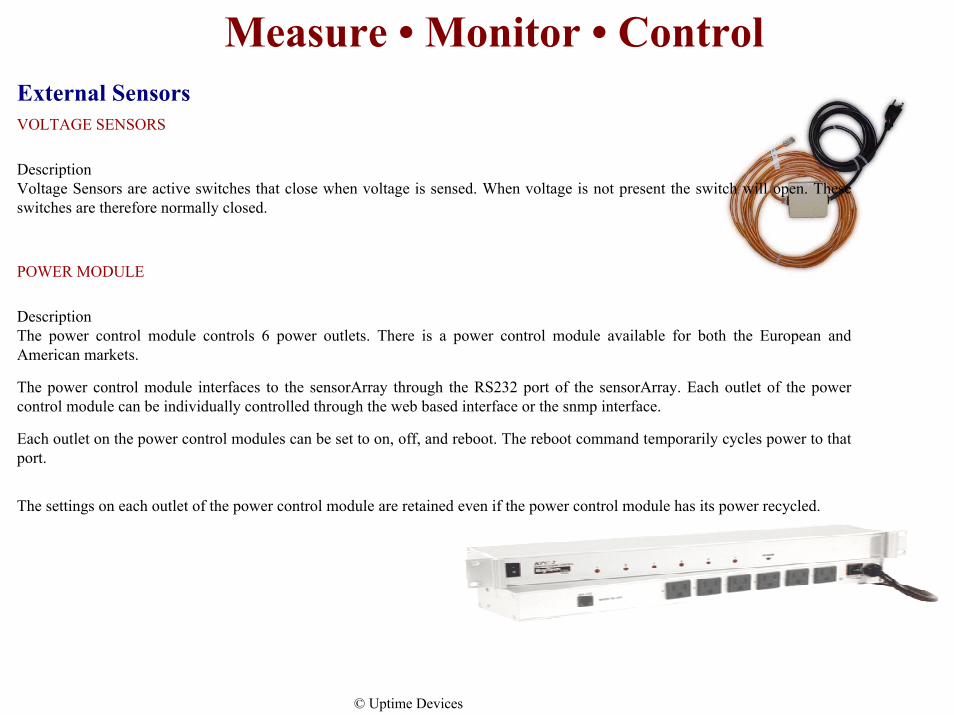
VOLTAGE SENSORS
Description Voltage Sensors are active switches that close when voltage is sensed. When voltage is not present the switch will open. These switches are therefore normally closed.
POWER MODULE
Description The power control module controls 6 power outlets. There is a power control module available for both the European and American markets.
The power control module interfaces to the sensorArray through the RS232 port of the sensorArray. Each outlet of the power control module can be individually controlled through the web based interface or the snmp interface.
Each outlet on the power control modules can be set to on, off, and reboot. The reboot command temporarily cycles power to that port.
The settings on each outlet of the power control module are retained even if the power control module has its power recycled.
External Sensors
© Uptime Devices

Power SolutionsVoltage DetectionVoltage Sensor - Detect the presence of AC voltage. 110V/220V. The voltage detector will report the loss of AC to the sensorArray generating an snmp trap to your network monitoring system. It can also generate an e-mail notification
Power MeteringRemote Power Sensor - a dual side power-sensing unit. The input and output for the remote power sensor is 20 Amp 115 VAC. It measures and reports: True RMS Current, TrueRMS Voltage, True Power in VA, Temperature.
The remote power sensor will report SNMP traps based on preset conditions for current, voltage, power and temperature.
Specifications :Power Input: (2) Non detachableNema L5-20P Power Output: (2)Nema L5-20R power receptacles Interface: RS-232 interface with RJ45 connector Indicators: Power and status indicator LEDs Mounting: Floor mount Dimensions: 8.25"w X 5"d X 2.59"h
Measure • Monitor • Control
© Uptime Devices

Measure • Monitor • Control
US Power Receptacles
Environment Dimensions Indicators Communications cable
Sensor Remote Control
Last settings saved on power loss
Power-up routine on power loss
Sensor power
Maximum number of power control modules per sensorArray
Six 15 Amp 110 V-AC receptacles Circuit Breaker: 125V, 15 Amp UL approved User definable names Call for other US configurations
Operating range 0°C +70°C Storage range -40°C +80°C
16.73"w x 5.25"d x 1.72"h, 19" rack or desk mount
One green power LED and six red LEDs indicate receptacle on/off status
RJ45 jack to sensor using 15 foot UTP Cat 5 wire.
on/ off all or individual receptacles via web or SNMP reboot all or individual receptacles via web or SNMP
Yes- will stay in last condition prior to power loss
Yes- The power-up routine to each receptacle left in the on position is performed sequentially to minimize power surges.
Requires external 110 V-AC 15 Amp power.
one- call if more are needed
Remote Power Control
Power Control Modules - Re-boot remotely. Control on, off or reboot to the recipticle level.
© Uptime Devices

Measure • Monitor • Control
Intelligent Power Strips
• 20 controllable Receptacles plus one always on. • True RMS current monitoring with overload alarm buzzer and indicator LED. • Individual or collective control of the receptacles. • Programmable unit ID and receptacle names. • Zero U Vertical-mount • Controllable via Network Management System using the sensorArray
In the event of a power failure to the unit itself, the 232 PowerStrip retains the most current operational status for each outlet in nonvolatile memory. When the PowerStrip regains power, it restores each outlet to those status settings. For example, if Outlet 1 and Outlet 2 are ON and the remaining outlets are OFF when a power loss occurs, Outlet 1 & 2 will be placed in the ON position automatically when power is restored. The power-up routine to each receptacle is performed sequentially to minimize power surges.
During normal operation, the intelligent powerStrip¹s circuit breaker status is "ON". If the circuit breaker status is "OFF," that indicates the circuit breaker has been tripped.
General Specifications:
Interface 9600 bps, EIA-232, eight-pin RJ45 connector. Environment Operating temperature range is from 0 to 40 degrees Celsius. Storage temperature range is from -40
to 80 degrees Celsius. Humidity tolerance is from 5 to 95 percent RH.Dimensions 1.75"w X 1.75"d X 65.76"h Indicators Green power LED, green receptacle status LED and red trip alarm LED Mounting Vertical aligned on standard rack Warranty One year on parts and labor Power Receptacles Twenty-one NEMA 5-15 receptacles 110V AC (+10%), 50/60 Hz, 20 Amps
Circuit Breaker 110V AC 20-Amps
Control The 232 PowerStrip is controlled by simple commands of ON, OFF and REBOOT. Access the internal menu through a serial connection through the sensorArray. Power Plug: L5-20P (Twist Lock), Optional 5-20P
© Uptime Devices
Measure • Monitor • Control
Camera
• We have done many successful installations integrating Axis network camera capabilities to capture and send e-mail upon trap conditions. You can view in real-time up to 4 Axis cameras simultaneously, in the Uptime Devices web interface
Measure • Monitor • ControlExternal Sensors
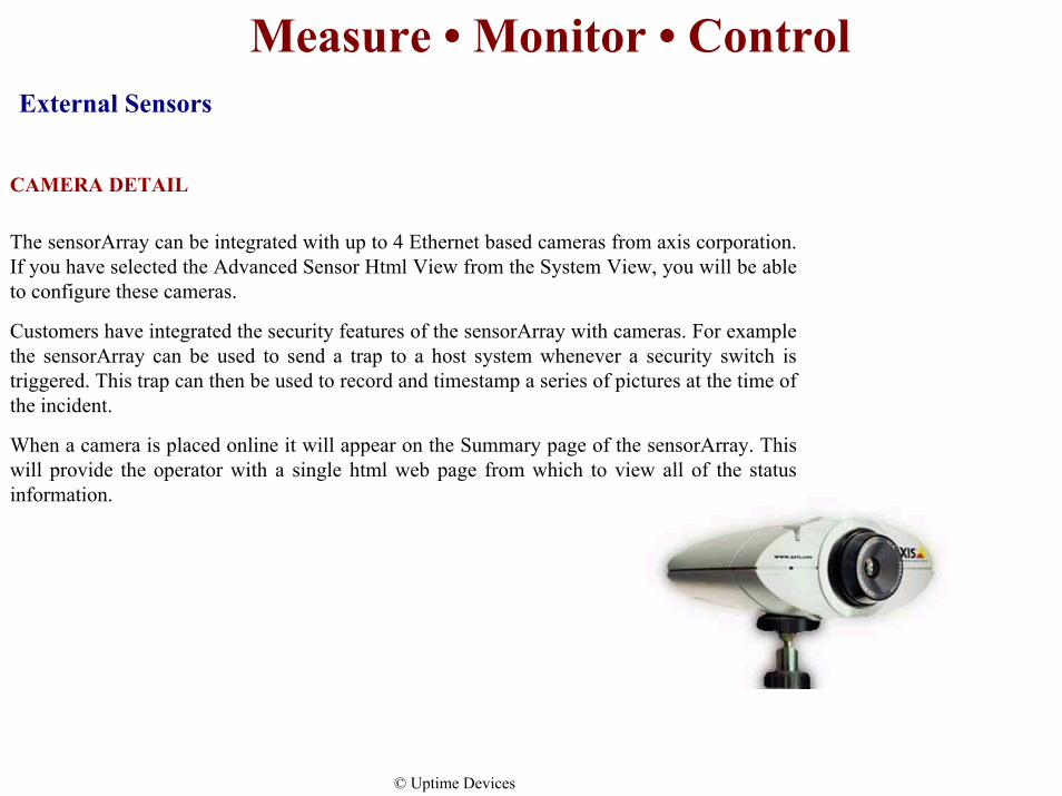
CAMERA DETAIL
The sensorArray can be integrated with up to 4 Ethernet based cameras from axis corporation. If you have selected the Advanced Sensor Html View from the System View, you will be able to configure these cameras.
Customers have integrated the security features of the sensorArray with cameras. For example the sensorArray can be used to send a trap to a host system whenever a security switch is triggered. This trap can then be used to record and timestamp a series of pictures at the time of the incident.
When a camera is placed online it will appear on the Summary page of the sensorArray. This will provide the operator with a single html web page from which to view all of the status information.
© Uptime Devices

Measure • Monitor • Control
Software Solutions
• We provide software solutions for data logging, graphing, and export. We have standalone versions for NT and all versions of Unix. We also have several packages written specifically as plug-ins for HP OpenView.

Measure • Monitor • ControlSoftware Solutions
OverTime Solo
What does OverTime Solo do?
1. For Input / Output devices like the sensorArray, routers, switches and hubs, OverTime uses SNMP to query the selected devices to see what Input/Output interfaces they have and sets up a Round Robin Database (RRD from Tobias Oetiker, the creator of MRTG and RRDTool). The RRD does not grow in size once setup.
OverTime Solo performs its own SNMP data collections. OverTime updates an index HTML page with the new devices. When you want to see the information collected, you simply drill down from the index page and OverTime graphs the collected data. An HTML page showing the most recent and detailed graphs for each interface on the device is displayed, along with IO errors for each interface and CPU utilization on supported devices.
All of the graphs on this device page are linked to more detailed views with four graphs being generated that show the information over progressively longer periods.
2. OverTime Solo can collect any numeric SNMP data and follows the same process as above except that the you specify which SNMP data to collect. This flexibility allows OverTime to record and graph such diverse information as Temperature &Humidity from an environmental monitor, Mail Queues from an e-mail system and disk space usage from servers. Labels for titles, legends and y-axis are automatically generated, but are easily modifiable by the user. 3. OverTime is used to display PingTime collected response time information.
Monitoring of device by OverTime can be stopped as easily as they were started.
OverTime makes the most efficient usage of the host system's resources by performing the least amount of work. SNMP collections are performed in bulk across the network, saving bandwidth. OverTime does not waste system time generating never-to-be-seen graphs. Graphs and HTML pages are only produced on user
request. Indeed, if two users are viewing the same page, only one of them will produce new graphs and the other views the graphs already generated.
OverTime SoloOverTime collects SNMP statistics from network devices and prepares HTML pages to graph the results.See all your network statistics OverTime.
© Uptime Devices
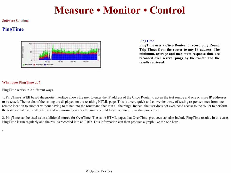
PingTimePingTime uses a Cisco Router to record ping Round Trip Times from the router to any IP address. The minimum, average and maximum response time are recorded over several pings by the router and the results retrieved.
Measure • Monitor • ControlSoftware Solutions
PingTime
What does PingTime do?
PingTime works in 2 different ways.
1. PingTime's WEB based diagnostic interface allows the user to enter the IP address of the Cisco Router to act as the test source and one or more IP addresses to be tested. The results of the testing are displayed on the resulting HTML page. This is a very quick and convenient way of testing response times from one remote location to another without having to telnet into the router and then run all the pings. Indeed, the user does not even need access to the router to perform the tests so that even staff who would not normally access the router, could have the ease of this diagnostic tool.
2. PingTime can be used as an additional source for OverTime. The same HTML pages that OverTime produces can also include PingTime results. In this case, PingTime is run regularly and the results recorded into an RRD. This information can then produce a graph like the one here.
.
© Uptime Devices
Measure • Monitor • ControlSoftware Solutions
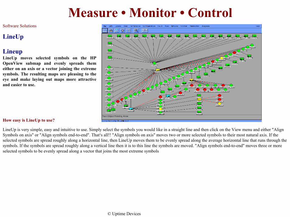
LineUp
How easy is LineUp to use?
LineUp is very simple, easy and intuitive to use. Simply select the symbols you would like in a straight line and then click on the View menu and either "Align Symbols on axis" or "Align symbols end-to-end". That¹s all!! "Align symbols on axis" moves two or more selected symbols to their most natural axis. If the selected symbols are spread roughly along a horizontal line, then LineUp moves them to be evenly spread along the average horizontal line that runs through the symbols. If the symbols are spread roughly along a vertical line then it is to this line the symbols are moved. "Align symbols end-to-end" moves three or more selected symbols to be evenly spread along a vector that joins the most extreme symbols
LineupLineUp moves selected symbols on the HP OpenView submap and evenly spreads them either on an axis or a vector joining the extreme symbols. The resulting maps are pleasing to the eye and make laying out maps more attractive and easier to use.
© Uptime Devices

Measure • Monitor • Control
Credentials
• Certifications by the best:– Hewlett-Packard (OpenView)– Computer Associates (TNG)– IBM (Tivoli)
• Award Winning Products:– “Best of Show” – Sensor Expo 2001
Measure • Monitor • Control
General Terms
• One-year warranty • Free Upgrades• Free support by e-mail and incoming calls• 30 day money back guarantee

Measure • Monitor • Control
Company Background• Uptime Devices’ history dates back to 1981 when Brad Klein started
AKCP providing solutions to major computer companies including DEC, Compaq, and Hewlett-Packard. The sensorArray has been in the field for over 3 years and has enjoyed a successful history of helping major enterprises manage their mission critical network management needs.
• Lawrence Latham - CEO Has served as President and Chief Executive Officer of successful growth companies in the high technology field including Aera Corporation, a process control and monitoring company for the semiconductor industry. His experience includes mergers and acquisitions and spans from the startup phase to global market leadership. Mr. Latham is active in the community and currently serves on several boards.

Measure • Monitor • Control
Company Background• Brad Klein – CTO
Since graduating in the top 5% of his class from the University of Massachusetts, Brad Klein has specialized in software development for operating system internals, communications, and routers for Fortune 500 companies such as Hewlett-Packard, Oracle, Compaq and DEC. Mr. Klein is the inventor of numerous Internet enabled, enterprise level, network equipment devices, including the industry leading sensorArray. The company Mr. Klein created in 1981 is now Uptime Devices.

Measure • Monitor • Control
Company Background• Laurie Gellatly
Laurie Gellatly has over 20 years experience in the computing industry. Technical expertise in various computing languages and network infrastructure including operating systems, LAN and WAN installation and management derived over the years working for international time sharing and investment banking institutions. A certified router specialist with experience in synchronous and asynchronous transmission protocols and the hardware that supports today's modern network infrastructures.