maximum power transfer tracking in a solar usb charger for smartphones
TRANSCRIPT

Maximum Power Transfer Tracking in a Solar USBCharger for Smartphones
Abstract—Battery life of high-end smartphones and tablet PCsis becoming more and more important due to the gap betweenthe rapid increase in power requirements of the electronic com-ponents and the slow increase in energy storage capacity of Li-ionbatteries. Energy harvesting, on the other hand, is a promisingtechnique that can prolong the battery life without compromisingthe users’ experience with the devices and potentially withoutthe necessity to have access to a wall AC outlet. Such energyharvesting products are available on the market today, butmost of them are equipped with only a large battery pack,which exhibits poor capacity utilization during solar energyharvesting. In this paper, we propose and demonstrate thatusing a supercapacitor instead of a large capacity battery canbe beneficial in terms of improving the charging efficiency, andthereby, significantly reducing the charging time. However, thisis not a trivial task and gives rise to many problems associatedwith charging the supercapacitor via the USB charging port. Weanalyze the USB charging standard and commercial USB chargerdesigns in smartphones to formulate an energy efficiency opti-mization problem and propose a dynamic programming-basedonline algorithm to solve the aforesaid problem. Experimentalresults show up to 34.5% of charging efficiency improvementcompared with commercial solar charger designs.
I. INTRODUCTION
Smartphone sales have grown very rapidly since 2007 andreached sales volume of 144.4 million units as of 2012 [1].State-of-the-art smartphones comprise high-performance ap-plication processors, high-bandwidth long term evolution(LTE) modems, and high resolution large sized displays thatconsume significant amount of power. However, there is onlyincremental progress in the battery capacity and technology.They are subject to volume and weight constraints that prohibitsignificant increase in battery capacity. Some smartphones donot even allow battery pack replacement. Thus, battery life isbecoming a key concern for such power consuming products.
It is a good idea to utilize an energy harvesting smartphonecharger to resolve the battery life issue. People often bringan external battery pack charged by a wall charger to relievebattery life problem for outdoor activities such as a campingand a hiking. However, energy harvesting chargers providesemi-permanent charging capability without looking for wallAC outlets unlike the external battery pack with a wall charger.Only some limited methods including solar energy harvestingor hand-crank generator among numerous harvesting methodsare suitable for smartphones due to its large power demand. Anumber of commercial chargers using solar power have beendeveloped. They focus on correct functionality, but system-level charging efficiency is not fully concerned.
Surprisingly, majority of low-cost smartphone solar chargersdo not perform the maximum power point tracking [2], [3]of the solar panel. We exclude such a solar charger setupfrom discussion in this paper. Smartphone solar chargers thatperform the maximum power point tracking rely on a large
Energy bufferCO
NFIDENTIALMPTT Solar USB Smartphone Charger
A new MPTT solar smartphone charger with a small size supercapacitorThe optimal supercapacitor SoC control
Supercapacitor size optimization
The huddle is that the solar irradiance does not change frequently on sunny daysStop-and-go is the only feasible way to achieve MPPT or MPTT
Collect charge in the supercapacitor with MPTT and charge the smartphone
How harmful and/or inefficient is frequent stop and go?
Assuming that the solar cell MPP is always lower than the required charging powerThis is even a more reasonable setup
Simultaneous current supply from the solar cell and supercapacitor when chargingThe PV cell is always supplying current to the supercapacitor
Determination of the supercapacitor SoC swing makes the problem novelTarget conference is DAC 2013
7
Supercapacitor
Charger
MPTTcontroller
DC-DCconverter
USBconnector
SoC
V
I
Solar charger
DC-DC converter
Solar-powered USB Charging port Smartphone
USB charging connector
MPPT
<500 mW >2.5 W
Fig. 1. USB-compatible solar charger architecture with an energy storagebuffer.
capacity battery pack. It has benefit in that it can providefull USB charging current for the portable device. However,their solar panel size does not match with the battery packcapacity. For example, Figure 1 shows a typical setup of asolar-powered USB charger. Commercial USB chargers drawpredetermined amount of current from USB charging port,and disconnect from the charging port if the amount is notsupported [4], [5]. Thus, an built-in battery should be used asan energy buffer as shown in Figure 1. Ideally, the averagepower output of the solar charger should not be smaller thanthe charging power, which is not the case. As an alternative,USB charging current could be gracefully reduced dependingon the change of irradiance intensity on the solar panel asa result of the maximum power point tracking (MPPT) [6],but such a feature is not defined in the USB charging portstandard, and commercial charger chips in smartphones haveno support for energy harvesting chargers. Therefore, the solarcharger cannot provide 100% duty power to the smartphone.It has to be charged for a while to be able to supportthe USB charging current since small-sized solar panel isunable to support the USB charging power by itself. Thebattery collects a certain amount of energy from the solarpanel using the MPPT while charging operation is stopped.The charging operation is resumed after the battery acquiresa certain amount of energy. Such a stop-and-go operationcontinues. As the size of the battery is much bigger than theamount of energy to be collected for the stop-and-go operation,the battery state-of-charge (SOC) is always close to empty,which is very inefficient in terms of capacity utilization. Thesmartphone users will eventually end up charging the built-in battery pack from the wall AC outlet to utilize its fullcapacity. We could also try fully charging the built-in batterypack before the solar panel is exposed to the sun. However,such operational scenario makes the solar charger as a typicalexternal battery pack. In addition, this would result in chargingthe two batteries sequentially and overall charging efficiencydegradation due to cycle efficiency. This is not applicableto long-term outdoor activities either. One can resolve thiscontradiction of low capacity utilization by using a small sizebattery. However, small size batteries are subject to a low cycle

ï4 ï2 0 2 40.7
0.8
0.9
1
Solar cell operating voltage
Out
put p
ower
Input/output voltage difference (V)
Con
vers
ion
effic
ienc
y(a) The output power of a solar cellaccording to its operating voltage.
(b) Variation in converter efficiencyaccording to input/output voltage
difference
Iout = 2 A
1.5 A
1 A
0.5 A
Fig. 2. The MPTT for energy harvesting devices.
efficiency due to low rate capability and a shorter battery lifedue to deep cycle operations during the stop-and-go operation.
In this paper, we propose to utilize a supercapacitor asan energy buffer in the USB-compatible solar charger forsmartphones. We propose to use a supercapacitor as the energybuffer in USB solar chargers. A supercapacitor is superiorin cycle life and efficiency compared with a battery, whichmakes a better candidate as an energy buffer and performingthe maximum power transfer tracking (MPTT) of USB solarchargers. However, a new problem arises when we considera supercapacitor as a buffer between the solar panel and theUSB charging port. The terminal voltage variation of a su-percapacitor causes degradation in associated power converterefficiency by offsetting the operating voltage and current fromthe optimal point. Thus, careful charge management such asthe MPTT should be performed to maximize the chargersefficiency [7]. Determination of the supercapacitor capacitanceand the SOC swing are also very crucial for the optimal solarcharger control.
We analyze the USB charging standard and commercialdesigns of USB charger in the portable device, and addressenergy efficiency problems in utilizing solar power and super-capacitor in such environment. We finally propose a dynamicprogramming based online charging algorithm for proposedbattery-less USB solar chargers. The proposed algorithm isfully compatible with the USB charging standard that makesit work applicable without modifications in commercial smart-phones.
II. BACKGROUND
A. Maximum Power Transfer Tracking and Conversion Effi-ciency
The V-I curve of a solar panel is generally far from an idealbattery, and thus it requires careful management to achievehigh energy efficiency as shown in Figure 2(a). The outputpower deviates significantly according to the operating voltage,current, and solar irradiance. The MPPT is a widely usedtechnique that tracks the optimal operating point of a solarpanel according to changing solar irradiance [6].
The power conversion loss of a power converter plays asignificant role in overall system energy efficiency. The energyefficiency of the power converters is a varying value that canbe expressed as a function of input voltage, output voltage,and output current.
η(Vin,Vout , Iout) =Pout
Pin=
Pin−Ploss
Pout. (1)
Cur
rent
(A)
Ibus
Ibat
Ibus,limit
0.5
1.0
0.5 1.0+
System loadUSB
charger
Ibus
Ibat
Iload
Rprg
Ibat,prg
0
(a) Battery and load connection to the USB-compatible charger
(b) USB charging current and batterycurrent vs. load current
ChargeDischarge
Iload(A)
Fig. 3. Programmable charger operation.
The variation of the conversion efficiency is more significantwhen considering a supercapacitor. The terminal voltage ofa supercapacitor varies linearly according to its SOC, whichaffects the efficiency of the associated power converters thatvaries significantly as shown in Figure 2(b). Therefore, it isessential to perform the MPTT that maximizes actual energydelivered from the energy harvesting device to the energystorage considering both power generation and conversionefficiency [7].
B. USB Charging Standard
USB charging specification is a de facto standard forcharging smartphone batteries. However, it is designed forpower sources such as wall AC outlet and large externalbatteries, and it does not support energy harvesting chargersthat often fail to meet the USB charging port requirementaccording to surrounding environment. Restrictions on theinput voltage and current of the commercial USB chargerchip in portable devices make it hard to enhance system-levelcharging efficiency of solar chargers using the MPTT. Solarchargers require continuous control of the charging current thatallows an arbitrary current value in the USB for performing theMPPT of the solar cell, which is true for a medium- to large-scale solar panels [6]. However, commercial USB compatiblecharger chips in smartphones do not allow room for continuouscontrol of charging current [4], [5].
A more detailed look of a USB-compatible solar chargeris shown in Figure 3. Battery charge current Ibat,prg is pro-grammed by a resistor Rprg as Ibat,prg = k/Rprg, which isusually fixed. The USB charging current Ibus is defined asthe input current of portable device side charger as shownin Figure 3(a). The value of Ibus is increased as the loadcurrent Iload increases. The maximum value of Ibus is fixedto Ibus,limit , so that Ibat has to be decreased if Ibus is clamped.Battery is discharged if Ibus only cannot support Iload . They aredisconnected from the USB charging port or abruptly reduceIbus when the USB charging port is unable to supply Ibus at anymoment during this operation. The USB charging port shouldsupport at least 0.5 A for standard downstream port (SDP),and 1.5 A for charging downstream port (CDP) and dedicatedcharging port (DCP). It is not defined in the standard how theportable device side charger should handle when the poweroutput of the charging port is insufficient. Our observationshows that many portable device side charger reduces theinput current limit to a predefined value to prevent failure ina “badly designed” charging port. The only feasible methodfor the MPTT without modifying commercial smartphones isstop-and-go based control.

Dedicatedport
USBcable
CONFIDENTIALMPTT Solar USB Smartphone Charger
A new MPTT solar smartphone charger with a small size supercapacitorThe optimal supercapacitor SoC control
Supercapacitor size optimization
The huddle is that the solar irradiance does not change frequently on sunny daysStop-and-go is the only feasible way to achieve MPPT or MPTT
Collect charge in the supercapacitor with MPTT and charge the smartphone
How harmful and/or inefficient is frequent stop and go?
Assuming that the solar cell MPP is always lower than the required charging powerThis is even a more reasonable setup
Simultaneous current supply from the solar cell and supercapacitor when chargingThe PV cell is always supplying current to the supercapacitor
Determination of the supercapacitor SoC swing makes the problem novelTarget conference is DAC 2013
7
Supercapacitor
Charger
MPTTcontroller
DC-DCconverter
USBconnector
SoC
V
I
USB charger
External power
Battery
(a) Patona 7in1 solar USB charger.
USB charger
Set pointcontrolCO
NFIDENTIALMPTT Solar USB Smartphone Charger
A new MPTT solar smartphone charger with a small size supercapacitorThe optimal supercapacitor SoC control
Supercapacitor size optimization
The huddle is that the solar irradiance does not change frequently on sunny daysStop-and-go is the only feasible way to achieve MPPT or MPTT
Collect charge in the supercapacitor with MPTT and charge the smartphone
How harmful and/or inefficient is frequent stop and go?
Assuming that the solar cell MPP is always lower than the required charging powerThis is even a more reasonable setup
Simultaneous current supply from the solar cell and supercapacitor when chargingThe PV cell is always supplying current to the supercapacitor
Determination of the supercapacitor SoC swing makes the problem novelTarget conference is DAC 2013
7
Supercapacitor
Charger
MPTTcontroller
DC-DCconverter
USBconnector
SoC
V
I
(b) MPPT using with dedicated mobile phone design.
Fig. 4. Previous solar USB charger topology.
CONFIDENTIAL
MPTT Solar USB Smartphone Charger
A new MPTT solar smartphone charger with a small size supercapacitorThe optimal supercapacitor SoC control
Supercapacitor size optimization
The huddle is that the solar irradiance does not change frequently on sunny daysStop-and-go is the only feasible way to achieve MPPT or MPTT
Collect charge in the supercapacitor with MPTT and charge the smartphone
How harmful and/or inefficient is frequent stop and go?
Assuming that the solar cell MPP is always lower than the required charging powerThis is even a more reasonable setup
Simultaneous current supply from the solar cell and supercapacitor when chargingThe PV cell is always supplying current to the supercapacitor
Determination of the supercapacitor SoC swing makes the problem novelTarget conference is DAC 2013
7
Supercapacitor
Charger
MPTTcontroller
DC-DCconverter
USBconnector
SoC
V
I
Solar charger
Input voltage regulation
Super-capacitor
Output voltageregulation
Input current limit
System load
Charge current
regulation
VBUSD+D-
GND
DC-DC converter
USB charger
Charging port Portable device
Output current limit
Fig. 5. Proposed USB-compatible solar charger architecture with a superca-pacitor buffer.
USB stop-and-go operation incurs some time and energyoverhead. USB charging standard defines charging port de-tection algorithm that distinguishes SDP, CDP, and DCP [8].The detection algorithm running on portable device side se-quentially performs VBUS detect, data contact detect, primarydetect, secondary detect, and ACA detect to determine thecharging port type. This typically takes several hundreds ofmilliseconds, which becomes minimum overhead of stop-and-go control. In this paper, we consider the time overhead only,which is constant once the system configuration is fixed.We assume the energy overhead of stop-and-go is negligibleconsidering relatively large USB charging power.
C. Existing Solar Charger Designs
There already are commercial chargers available in themarket. The simplest and cheapest solution is connectionof a solar panel to the smartphone with diodes such asPatona 7in1 solar charger for smartphones, which is shownin Figure 4(a) [2]. However, this design has shortcomings inthat cannot perform the MPPT, and discards solar energy whensolar panel output power is below a threshold. Solar chargerswith a DC–DC converter may perform the MPPT. A recentwork has explored the possibility of using the CPU in mobilephones as a microcontroller for performing the MPPT [3]. Thesolar panel is connected to the mobile battery via a DC–DCconverter without any built-in energy storage in the design asshown in Figure 4(b). However, it requires another chargingport from the smartphone besides the USB interface, which isnot the usual case for general smartphones, because it performscontinuous control of charging current. We need an energybuffer as shown in Figure 1 to perform energy efficiencyoptimization such as the MPTT while meeting USB chargingstandard. However, no extensive work has been performed onenergy efficient design and control of USB-compatible solarchargers. Existing solar chargers for smartphones generallyrely on large capacity Li-ion batteries [9], [10] and are subjectto problems as we discussed in Section I.
(b) Small supercapacitor terminal voltage swing
Time
Supe
rcap
acito
rvo
ltage
Systemefficiency
Stop-and-gooverhead
Time
Supe
rcap
acito
rvo
ltage
GoperiodHigher
efficiency(a) Large supercapacitor terminal voltage swing
Stopperiod
Stopperiod
Goperiod
Fig. 6. Trade-off relationship between converter efficiency loss and USBstop-and-go overhead.
III. PROPOSED SOLAR CHARGER DESIGN AND CONTROLALGORITHM
A. Solar Cell-Supercapacitor Hybrid Architecture
In this paper, we propose to use a supercapacitor as anenergy buffer for performing the MPTT in USB-compatiblesolar charger for smartphones. Figure 5 shows the proposedarchitecture of the conventional charger. The energy capacityof the supercapacitor is much smaller than built-in batterypacks used in commercial products because it is not for long-term energy storage but used as an intermediate buffer toperform the MPTT. Usage of supercapacitor induces newissues including supercapacitor SOC change, which affectsoverall system efficiency. The conversion efficiency of threeconverters in Figure 5 varies according to supercapacitorterminal voltage change as shown in Figure 2(b). If thesupercapacitor terminal voltage is maintained too low or toohigh, there will be higher conversion loss in the converters, andless energy will be delivered to the mobile device. There existsthe optimal supercapacitor terminal voltage that minimizesthe conversion loss in the converters. We thus intend to findthe optimal supercapacitor terminal voltage to minimize theconversion loss and thus maximize the charging power to thesmartphone. The USB charging standard leaves stop-and-gocontrol as the only option as discussed in Section II-B. Theterminal voltage of the supercapacitor should swing up anddown the optimal value due to stop-and-go control as shownin Figure 6. The conversion loss could be large depending onthe control of stop-and-go control. For example, excessivelycoarse-grain control would make the solar charger and DC–DCconverter in Figure 5 and operate it in low efficiency region fora significant amount of period as shown in Figure 6(a). Fine-grain stop-and-go control enables the associated converters tooperate more in the high-efficiency region, but the overallcharging process would be inefficient due to the large stop-and-go overhead as shown in Figure 6(b).
B. Charging Efficiency Maximization Problem Formulation
The objective of the control algorithm is to maximize theaverage charging power Pbat for the battery in a mobile device.Average charging power is average battery input power overthe total charging time compensated by non-idealistic battery

Time
Supe
rcap
acito
rvo
ltage
Charger ��� Charger ON
Time quantum
...
...
Time slot
...... ...
Time slot
Total charging time
�������OFF
tonOv
to f f Ov
�������ON
Ttotal
Dt
Fig. 7. Terms for charging efficiency-optimal SOC swing subproblem.
characteristics such as internal resistance and rate capacityeffect. The objective function is formally given as
Pbat =1
Ttotal
Ntotal∑n=1
Pbat,e f f [n]∆t, (2)
where Ttotal is the charging time, Pbat,e f f [n] is the actual charg-ing power of the battery at time quantum qn that allows fornon-ideal battery characteristics such as limited rate capacitycapability [11], ∆t is the length of the time quantum, and Ntotalis the number of the time quanta that satisfy Ttotal = Ntotal ·∆t,respectively. This objective is equivalent to charging timeminimization as charging time will be minimized if the averagecharging power is maximized. The detailed terms are given inFigure 7.
Given values for the problem are solar irradiance G, systemload current IL, supercapacitor SOC, SOCcap, and battery SOC,SOCbat at the beginning of a time slot. Making predictionson future G and IL would benefit for stationary solar powerplants and rooftop solar panels etc., which are located ina place that can be free from fast environmental conditionchange as much as possible. However, prediction of G andIL is limited for a portable smartphone solar charger. Loadcurrent of semiconductor components in a smartphone indeedcontains high frequency components, but they are filteredout by bulk capacitors in the power converters. Therefore,the current waveform at the charger input does not containdominant high frequency components over 1 kHz. Thus, weconsider an online algorithm based on the currently measuredcurrent. We assume that the solar irradiance and load demanddo not change within a time slot, which is not longer than a fewseconds. The power conversion efficiency of the solar charger,DC–DC converter, and USB charger influences the overallcharging efficiency significantly. The conversion efficiencyis well modeled as a function of its input voltage, outputvoltage, and output current [7]. Functions ηsolar(Vin,Vout , Iout),ηDC(Vin,Vout , Iout), and ηUSB(Vin,Vout , Iout) denote conversionefficiency of the solar charger, DC–DC converter, and USBcharger, respectively.
The control knob for optimization is on/off control of theUSB charging for each time quantum. We define a variableUSB to accommodate the control knob. Variable USB hasone of the following four charging decisions, “ON”, “OFF”,“TURNING ON”, and “TURNING OFF”. The output ofthe control algorithm is the energy optimal on/off chargingschedule, that is USB[n] for every time quantum qn.
C. Solution Method
We propose an online algorithm that follows dynamic loadand solar irradiance change at runtime. Power generation ofthe solar cell depends on the weather conditions, obstacles,and direction of the solar panel, which dynamically changeduring runtime. The proposed method is an online discretetime approach that performs Algorithm 1 every time slot.Algorithm 1 finds the optimal charge scheduling using dy-namic programming. Each time quantum becomes the decisionstage of the dynamic programming algorithm, and the algo-rithm determines the charging state decision USB. We firstformulate the problem Swing(Vcap,N ,N) that finds chargingefficiency-optimal schedule (maximized (2)) that makes thesupercapacitor voltage at time T = N · ∆t to be Vcap,N . Weapply dynamic programming to solve Swing(Vcap,N ,N) sothat Swing(Vcap,N ,N) should satisfy the optimal substructureproperty in order to exploit dynamic programming.
The optimal substructure property of Swing(Vcap,N ,N)problem: Suppose a sequence of τN = {(Vcap[n], usb[n]) 1≤n≤ N}, is the optimal solution of Swing(Vcap,N ,N). A subse-quence τM = {(Vcap[m], usb[m]), 1≤ m≤M where M < N},is the optimal solution of Swing(Vcap,M,M), a subproblem ofSwing(Vcap,N ,N).
Proof: There exists a different sequence υM that exhibitshigher charging efficiency than τM if the subsequence τM isnot the optimal solution for Swing(Vcap[M],M). This impliesthat a sequence that is a concatenation of υM and the tail ofτN should exhibit a higher efficiency than τN . This contradictsto the assumption that τN is the optimal solution, and thus, theoptimal substructure property is proved.
Algorithm 1 explains how SOC swing should be man-aged to achieve high charging efficiency. We build a two-dimensional table, TSOC,n[Vcap,USB], for each time quantumqn using dynamic programming. Table indexes are quantizedvalue of Vcap and the charging decision USB. The entry valueof TSOC,n[Vcap,USB] is the expected battery SOC, SOCbat , attime quantum qn + 1 when supercapacitor voltage at timequantum qn is Vcap, and selected charging decision is USB.Algorithm 1 shows the SOC swing determination algorithmaiming at the maximum efficiency. The algorithm initial-izes the first table such that TSOC,0(Vcap,0,USB0)← SOCbat,0and fill the rest of the tables using dynamic programming.Function nextValue(G, IL,Vcap,nxtStat) calculates the super-capacitor voltage and battery SOC for the next time slotdepending on nxtStat using the component models discussedin Section II-A. We perform backtracing to obtain the optimalcharging schedule after table construction is finished. Theselection of (Vcap,USB) pair in TSOC,N to start backtracingis very important. Greedy approach per time slot that picks(Vcap,USB) pair with the highest battery SOC value in TSOC,Nis not the globally optimal as it results in discharging the super-capacitor buffer as much as possible within a time slot to max-imize the smartphone battery charging power. The algorithmshould charge the supercapacitor up to certain voltage level atthe next time slot, which is energy inefficient. Thus, we pickappropriate (Vcap,opt ,USBopt) in TSOC,N to start backtracing byAlgorithm 2 offline. We construct a look up table by offline
Algorithm 1: Optimal supercapacitor SOC swing algo-rithm.
Input: G, IL, SOCbat,0, Vcap,0Output: Charging schedule USBStat[n] for every n
1 for n = 0→ N do2 for ∀(Vcap,USB) do3 TSOC,n(Vcap,USB)←−1
4 TSOC,0(Vcap,0,∀USB)← SOCbat,05 for n = 0→ N−1 do6 for ∀(Vcap,USB) pair do7 if TSOC,n(Vcap,USB) =−1 then8 continue9 if USB=OFF then
10 for nxtStat = OFF, TURNING ON do11 (Vcap,nxt,SOCbat,nxt)←
nextValue(G, IL,Vcap,nxtStat)12 if SOCbat,nxt > TSOC,n+1(Vcap,nxt,nxtStat) then13 TSOC,n+1(Vcap,nxt,nxtStat)← SOCbat,nxt14 Prevn+1(Vcap,nxt,nxtStat)← (Vcap,USB)
15 else if USB=TURNING ON then16 nxtStat = ON17 (Vcap,nxt,SOCbat,nxt)←
nextValue(G, IL,Vcap,nxtStat)18 if SOCbat,nxt > TSOC,n+1(Vcap,nxt,nxtStat) then19 TSOC,n+1(Vcap,nxt,nxtStat)← SOCbat,nxt20 Prevn+1(Vcap,nxt,nxtStat)← (Vcap,USB)
21 else if USB=ON then22 for nxtStat = ON, TURNING OFF do23 (Vcap,nxt,SOCbat,nxt)←
nextValue(G, IL,Vcap,nxtStat)24 if SOCbat,nxt > TSOC,n+1(Vcap,nxt,nxtStat) then25 TSOC,n+1(Vcap,nxt,nxtStat)← SOCbat,nxt26 Prevn+1(Vcap,nxt,nxtStat)← (Vcap,USB)
27 else if USB=TURNING OFF then28 nxtStat = OFF29 (Vcap,nxt,SOCbat,nxt)←
nextValue(G, IL,Vcap,nxtStat)30 if SOCbat,nxt > TSOC,n+1(Vcap,nxt,nxtStat) then31 TSOC,n+1(Vcap,nxt,nxtStat)← SOCbat,nxt32 Prevn+1(Vcap,nxt,nxtStat)← (Vcap,USB)
33 Vcap,opt ← LUTVcap(G, IL)34 USB← maxargUSB(TSOC,N(Vcap,opt ,USB))35 for n = N→ 0 do36 (Vcap,USB) = Prevn(Vcap,USB)37 USBStat[n]←USB
characterization in the form of Vcap,opt = LUTVcap,opt (G, IL).The algorithm sweeps Vcap and calculates the value thatminimizes the conversion loss from the solar panel to themobile device. Backtracing from TSOC,N(Vcap,opt ,USBopt) toTSOC,0(Vcap,0,USB0) gives the optimal charging schedule.
IV. EXPERIMENTS
We show the efficacy of the proposed design and onlinecharging algorithm compared with commercial chargers withthe MPPT capability. We evaluate the performance of theproposed design and the online charging algorithm on mostgeneral setups. The size of the solar panel used for experiments
Algorithm 2: Offline algorithm for finding Vcap,opt , whichis starting point of backtracing.
Input: Solar irradiance G, Load current ILOutput: Backtracing starting voltage Vcap,opt
1 Ibat,max← 02 for ∀quantized(Vcap,G, IL) do3 (Vsolar, Isolar)←MPT T (G,Vcap)4 Psolar←Vsolar · Isolar5 Isolar,out ← f indI
(ηsolar(Vsolar,Vcap, I) ·Psolar =Vcap · I
)6 IDC,in← Isolar,out7 PDC,in←Vcap · IDC,in8 IDC,out ← f indI
(ηDC(Vcap,VUSB, I) ·PDC,in =VUSB, I
)9 IUSB,in← IDC,out
10 PUSB,in←VUSB · IUSB11 Ibat ← f indI
(ηUSB(VUSB,Vbat , IL, I) ·PUSB,in = PL +Vbat · I
)if Ibat > Ibat,max then
12 Ibat,max← Ibat13 LUTVcap(G, IL)←Vcap
(b) Charging profile for baseline 1
(c) Charging profile for baseline 2
(d) Proposed algorithm
(e) Supercapacitor terminal voltage swing
Syst
em lo
ad (W
)
(a) Solar irradiance and system load profile
Time (minutes)0
Smar
tpho
neba
ttery
SO
C (%
)
Bui
lt-in
bat
tery
SOC
(%)
10
2040
20
0
Mobile battery SOCExternal battery SOC
20 40 60 80
Time (minutes)
Bui
lt-in
bat
tery
SOC
(%)
0
Smar
tpho
neba
ttery
SO
C (%
)
10
20
0
20
40Mobile battery SOCExternal battery SOC
20 40 60 80
Time (minutes)
Supe
rcap
acito
rvo
ltage
(V)
0 Smar
tpho
neba
ttery
SO
C (%
)
20 40 60 80
5
10
0
20
40Supercapacitor voltageMobile battery SOC
Time (minutes)
Sola
r irr
adia
nce
(mW
/cm
2 )
600700800900
1000
0
0.6
1.2 Solar irradianceSystem load
20 40 60 80
Time (seconds)
Supe
rcap
acito
rvo
ltage
(V)
5.7
5.8
5.9
1200 1220 1240 1260 1280
Supercapacitor voltageOptimal capacitor voltage Vcap,opt
Fig. 8. Comparison of battery charging process over time.
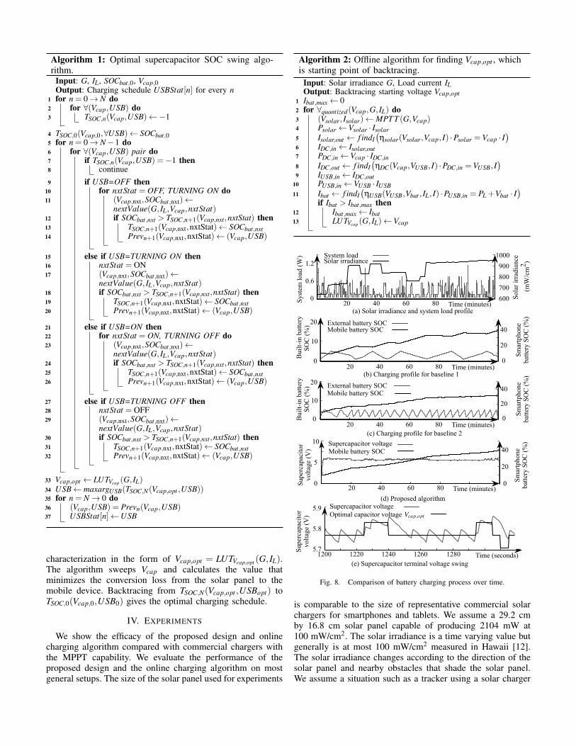
is comparable to the size of representative commercial solarchargers for smartphones and tablets. We assume a 29.2 cmby 16.8 cm solar panel capable of producing 2104 mW at100 mW/cm2. The solar irradiance is a time varying value butgenerally is at most 100 mW/cm2 measured in Hawaii [12].The solar irradiance changes according to the direction of thesolar panel and nearby obstacles that shade the solar panel.We assume a situation such as a tracker using a solar charger
attached on the backpack, and the perceived solar irradiancechanges according to direction of walking. The smartphonebattery is an Li-ion battery with capacity of 1500 mAh. Thesmartphone system load changes according to usage patternof the users and application behaviors.
We compare the proposed architecture and algorithm withtwo baselines. The first baseline is the solar charger witha large built-in battery pack of 2000 mAh capacity in thecharger. Comparison is made for the steady-state long-termoutdoor usage cases, and we assume zero initial SOC forall the setups. The solar panel is controlled by the MPPTalgorithm to maximize its output power. We perform stop-and-go operation for baselines as explained in Section 1. Thesecond baseline is a solar charger with a small buffer battery,and all the other components in the experimental setup are keptthe same. We show the efficacy of our proposed algorithm forvarious sizes of supercapacitors.
Figure 8 shows the comparison between the baselines andproposed algorithm for two hours of charging. Figure 8(a)shows the profile of solar irradiance and system load. Solarirradiance profile is generated based on data measured inHawaii by NREL [12] and modified to reflect changes ofthe solar panel direction and shading. We use a syntheticsmartphone load with the maximum value of about 1.5 W.Figure 8(b) shows charging process of the first baseline. Thebuilt-in battery pack of 1.5 Ah capacity is charged from thesolar panel until its SOC reaches a threshold. The chargercircuitry determines the open circuit voltage of the built-inbattery and discharges it when it has accumulated enoughcharge. The threshold value generally small, so we assume it tobe 5% in our setup. Figure 8(c) shows charging process of thesecond baseline, which uses much smaller battery than the firstbaseline, 300 mAh. We compared the proposed method withbaselines when there is change in surrounding environmentsuch as solar irradiance and system load for more directcomparison.
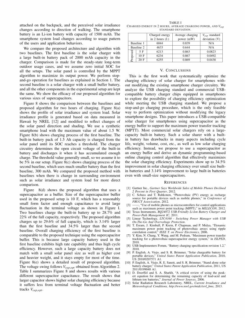
Figure 8(d) shows the proposed algorithm that uses asupercapacitor as a buffer. Size of the supercapacitor bufferused in the proposed setup is 10 F, which has a reasonablysmall form factor and enough capacitance to avoid largefluctuation in the terminal voltage as shown in Figure I.Two baselines charge the built-in battery up to 28.7% and22% of the full capacity, respectively. The proposed algorithmcharges up to 29.6% of full capacity, which is 3.14% largerthan the first baseline and 34.5% larger than the secondbaseline. Overall charging efficiency of the first baseline iscomparable to the proposed technique using the supercapacitorbuffer. This is because large capacity battery used in thefirst baseline exhibits high rate capability and thus high cycleefficiency. However, such a large capacity battery does notmatch with a small solar panel size as well as higher costand heavier weight, and it stays empty for most of the time.Figure 8(e) shows a detailed result of proposed algorithm.The voltage swing follows Vcap,opt obtained from Algorithm 2.Table I summarizes Figure 8 and shows results with variousdifferent supercapacitor capacitance. The result shows thatlarger capacitor shows higher solar charging efficiency becauseit suffers less from terminal voltage fluctuation and bettertracks Vcap,opt .
TABLE ICHARGED ENERGY IN 2 HOURS, AVERAGE CHARGING POWER, AND Vcap
STANDARD DEVIATION.
Charged energy Average charging Vcap standardin 2 hours (J.) power (mW) deviation (V)
Baseline 1 6044 0.839 N/ABaseline 2 4633 0.644 N/A
Prop
osed 5 F 6213 0.863 0.0823
10 F 6234 0.867 0.049220 F 6255 0.869 0.0438
V. CONCLUSIONS
This is the first work that systematically optimize thecharging efficiency of solar charger for smartphones with-out modifying the existing smartphone charger circuitry. Weanalyze the USB charging standard and commercial USB-compatible battery charger chips equipped in smartphonesto explore the possibility of charging efficiency optimizationwhile meeting the USB charging standard. We propose astop-and-go charging procedure, which is the only feasibleway to perform optimization without modifying the legacysmartphone designs. This paper introduces a USB-compatiblesolar charger for smartphones using supercapacitor as theenergy buffer to support the maximum power transfer tracking(MPTT). Most commercial solar chargers rely on a large-capacity built-in battery. Such a solar sharer with a built-in battery has drawbacks in many aspects including cyclelife, weight, volume, cost, etc., as well as low solar chargingefficiency. Instead, we propose to use a supercapacitor asan energy buffer and derive an dynamic programming-basedonline charging control algorithm that effectively maximizesthe solar charging efficiency. Experiments show up to 34.5%improvement in solar charging efficiency over small size built-in batteries and 3.14% improvement to large built-in batterieseven with small-size supercapacitors.
REFERENCES
[1] Gartner Inc., Gartner Says Worldwide Sales of Mobile Phones Declined2 Percent in First Quarter, 2012.
[2] C. Schuss and T. Rahkonen, “Photovoltaic (PV) energy as rechargesource for portable devices such as mobile phones,” in Conference ofFRUCT Assocication, 2012.
[3] ——, “Use of mobile phones as microcontrollers for control applicationssuch as maximum power point tracking (MPPT),” in MELECON, 2012.
[4] Texas Instruments, BQ24072 USB-Friendly Li-Ion Battery Charger andPower-Path Management IC, 2011.
[5] Linear Technology, LTC4160 - Switching Power Manager with USBOn-The-Go And Overvoltage Protection.
[6] T. Esram, J. Kimball, P. Krein, P. Chapman, and P. Midya, “Dynamicmaximum power point tracking of photovoltaic arrays using ripplecorrelation control,” IEEE T. on Power Electronics, 2006.
[7] Y. Kim, N. Chang, Y. Wang, and M. Pedram, “Maximum power transfertracking for a photovoltaic-supercapacitor energy system,” in ISLPED,2010.
[8] USB Implementers Forum, “Battery charging specification revision 1.2,”2010.
[9] P. English, A. Viejo, and S. R. Brimmer, “Solar chargeable battery forportable devices,” United States Patent Application Publication, 2010,US 2010/0207571 A1.
[10] P. English, A. Viejo, R. E. Sanett, and S. R. Brimmer, “Stand alone solarbattery charger,” United States Patent Application Publication, 2011, US2011/0199040 A1.
[11] D. Doerffel and S. A. Sharkh, “A critical review of using the peuk-ert equation for determining the remaining capacity of lead-acid andlithium-ion batteries,” Journal of Power Sources, 2006.
[12] Solar Radiation Research Laboratory, NREL, Current Irradiance andMeteorological Conditions, http://www.nrel.gov/midc/srrl bms, 2013.