maximum dynamics and limitless precision for codesys
TRANSCRIPT
SD6 Drive Controller
Maximum dynamics and
limitless precision for
CODESYS controlled axes

Perfect precision control ofservo axes with EnDat® 2.2encoders
With the speed feedback via EnDat®
2.2 encoders, about 33 million
positions per revolution can be
determined.
The 32-bit Dual-Core processor on
the SD6 drive controller processes
the encoder data with maximum
accuracy and speed. With its high
computing capacity, the SD6 drive
controller can also be used with fu-
ture encoder systems with higher
resolution.
A 32-bit format is available for the
reference value/actual value inter-
face. So positions can be represented
with high precision and a large po-
sition range.
SPEED | FLEXIBILITY | DESIGN
Ready for anything with 32-bit Dual-Core processor
2

Specially for motion control solutions
The new STÖBER 6th
generation device
The completely redesigned STÖBER
6th generation device starts with
the SD6 drive controller and MC6
motion controller.
Based on a combination of the two
devices, the drive controller is oper-
ated in Controller Based Mode (CBM).
EtherCAT® and CANopen®
device communication
The STÖBER CBM application is based
on the internationally standardized
device profile CiA 402 for electric
drives and motion control.
The SD6 drive controller is actuated
by the CiA 402 compliant control
words, status words, reference val-
ues and actual values.
3
The 32-bit Dual-Core controlperformance gives a newdimension to motion preci-sion and smoothness
Position, speed and torque control
of the servo axes are calculated at
a cycle time of 62.5 μs (16 kHz).
This allows extremely high dynam-
ics and precision of the drives due
to very short settling times for fast
reference values changes and step
changes in load.
The new SD6 drive controller offers
the possibility of a significant and
impressive increase in precision and
productivity in automation engi-
neering and machine manufacture
despite the ever-increasing com-
plexity of the functions.
With the high performance SD6
drive controller, the constant cus-
tomer demands for faster cycle
times and an increase in output can
be convincingly and reliably met.
The SD6 drive controlleroperating modes
� Interpolated position mode
(CANopen®)
Cyclic position input by the
motion controller – the drive
follows in position control
� Cyclic synchronous
position mode (EtherCAT®)
Cyclic position input by the
motion controller – the drive
follows in position control
� Cyclic synchronous
velocity mode (EtherCAT®)
Cyclic speed input by the
motion controller – the drive
follows in speed control
� Cyclic synchronous
torque mode (EtherCAT®)
Cyclic torque input by the
motion controller – the drive
follows in torque control
� Type/STÖBER specific mode
Control-independent travel
of the drive – e.g. for set up
functions and emergency mode
� Homing mode
Control-independent refer-
encing by the drive – the drive
calculates the necessary travel
profiles independently6th generation device
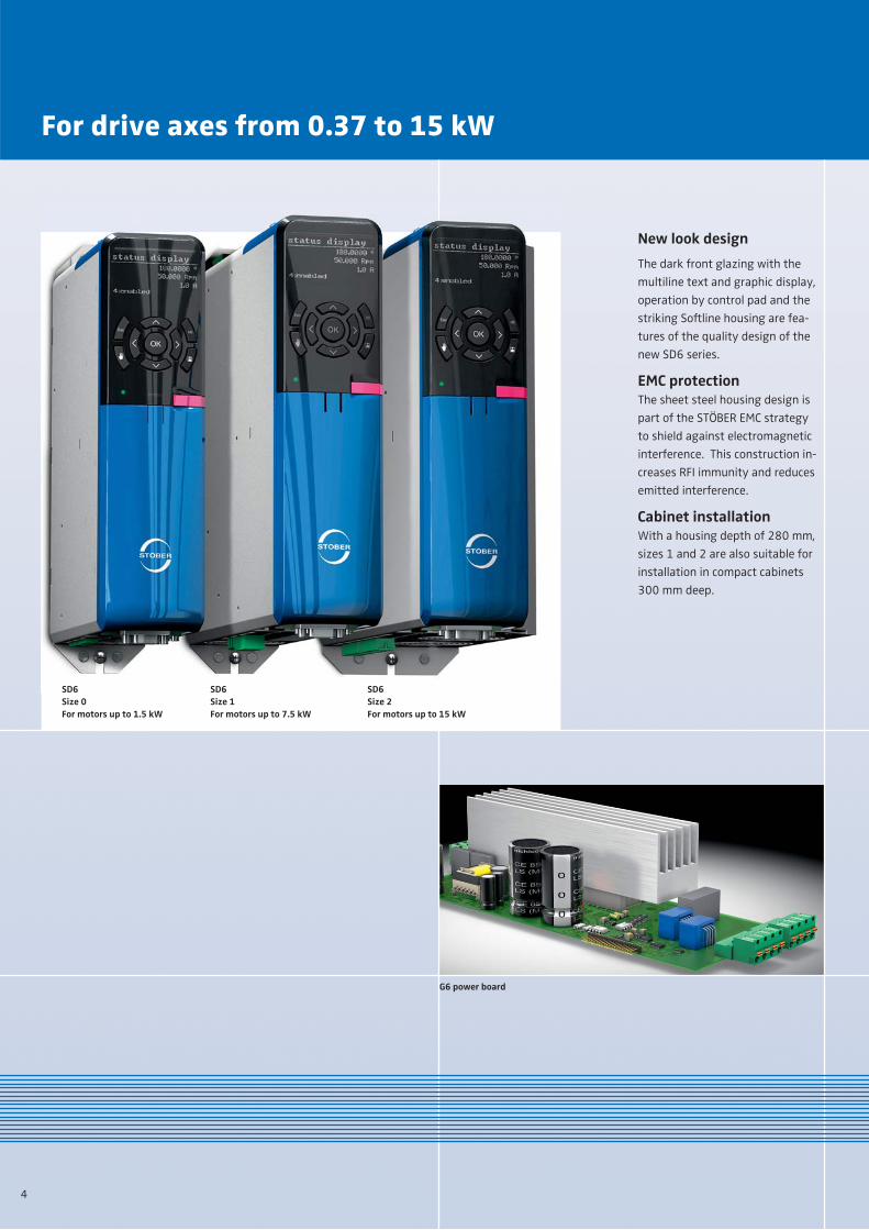
New look design
The dark front glazing with the
multiline text and graphic display,
operation by control pad and the
striking Softline housing are fea-
tures of the quality design of the
new SD6 series.
EMC protectionThe sheet steel housing design is
part of the STÖBER EMC strategy
to shield against electromagnetic
interference. This construction in-
creases RFI immunity and reduces
emitted interference.
Cabinet installationWith a housing depth of 280 mm,
sizes 1 and 2 are also suitable for
installation in compact cabinets
300 mm deep.
For drive axes from 0.37 to 15 kW
SD6 Size 0For motors up to 1.5 kW
SD6 Size 1For motors up to 7.5 kW
SD6 Size 2For motors up to 15 kW
4
G6 power board

The connections for motor, DC link, braking resistor and holding brake arelocated on the underside of the device
The SD6 drive controller stands out
for its proven board architecture and
its universal options.
So every single system axis in the
configuration can have the best
design.
A control for a 24V holding brake is
integrated (<= 2.5 A)
A non-wearing, fully electronic in-
terface is provided as standard for
the Safe Torque Off (STO) safety
function. (response time < 10 ms)
Modular flexibility and options
The quick mains or 24V connection is made from above through plug-in terminal strips
EtherCAT® connection for motion control operation
Paramodul with micro SD card for storage of all device data
Safety board connector (developed jointlywith Pilz GmbH & Co. KG)
5
SD6 size 0 – housing cover removed to show terminal boardsLeft: terminal board X16, right: terminal board IO6
A technically innovative solution
allows the STO safety function to
work without interruptive system
tests and their documentation. In
practice this means impressively
increased availability.
On multiaxis applications with SD6
drive controllers, it is possible sim-
ply to loop through the STO safety
function.
Functional safety data are provided
for standard market calculation tools
for system safety (e.g. Sistema,
Pascal).
The safety relevant functions were
developed jointly with Pilz GmbH &
Co. KG.

High performance – forcomplex motion profiles of the drive axesIn multiaxis operation every geared
motor has its task and conditions.
Multiaxis applications with high
dynamics can only be achieved if
the drive controllers are capable of
guaranteeing precision and timing
in all circumstances.
The high performance SD6 drive
controller is ideal for these appli-
cations.
... perfectly coordinatedwith synchronous servomotors from STÖBERWith this extensive hardware range,
virtually all requirements in machine
manufacture and automation can
be met.
Designed for multiaxis operation
Drive controller in multiaxis operation, controlled by the STÖBER MC6 motion controller via EtherCAT®
A selection of the servo drive product range from STÖBER
6

Typical uses can be found in winding
technology, storage and retrieval
units, conveyor and handling sys-
tems and installations with vertical
axes.
A common DC link configuration
can also be a consideration if sev-
eral drives with braking resistors
are used or planned in an installa-
tion.
For optimized use of the ‘self-gen-
erated’ energy, it is necessary to
coordinate the drive sequences and
motion profiles and control them
via the MC6 motion controller.
Common DC link configuration for more energy efficiency
Submounted G6 DC link with concealed busbar for DC link connection, with an added brake resistor
7
Options for energy use of a DC link connectionAll the SD6 drive controller series
have a DC link connection facility.
With this technology the regenera-
tive energy from one servo drive
can be absorbed and used by an-
other motoring servo drive on the
same DC link line.
Regenerative energy occurs when a
load drives the motor and energy is
returned to the drive controller.
If operating conditions change fre-
quently or regularly from motoring
to regenerative mode, it can make
sense to feed the surplus energy
generated to one or more drive
controllers or servo drives. This is
done through the DC link connec-
tion referred to.
Quick DC Link
The Quick DC Link rear-mounted
module was developed to offer a
secure and efficient bus connection
for a common DC link configuration.
The contact between the SD6 drive
controllers is made by standard bus-
bars (5 x 12). They are installed
without tools by quick-fix clamps.
The Quick DC Link modules come
with an integral fuse.
Safe and reliable through motion control

Software, solutions and user seminars
DriveControlSuite
The DriveControlSuite commission-
ing software version 6 has all the
functions for efficient use of drive
controllers in multiaxis applications.
Commissioning is made easy, for
example by a multiaxis oscilloscope.
Integrated bus (IGB)
The IGB network makes real time
control of a variety of communica-
tion and diagnosis concepts between
several drive controllers and inter-
faces possible.
This interface is ideal for direct
connection between PC and drive
controller.
CODESYS – the software for multiaxis operation
CODESYS – from 3S-Smart Software
Solutions – is a hardware independ-
ent programming software or a
complete programming system for
the international standard PLC lan-
guages according to IEC 61131-3.
The centralization of all the axis
parameters in one program opera-
tion makes it easier to program
complex multiaxis applications.
Examples of these are path travel,
CNC and robotic functions.
Due to its wide popularity, this soft-
ware tool represents the de facto
market standard for hardware in-
dependent development systems.
Many users, particularly in the au-
tomation industry, are perfectly
familiar with CODESYS.
The new MC6 motion controller from
STÖBER (see separate brochure)
is already equipped with the new
CODESYS V3 version.
Application support andtailor-made services
STÖBER offers you support and
services specially matched to your
requirements.
You can also make use of the STÖBER
technology support for troubleshoot-
ing or optimization of an existing
system.
With the design and programming
of a Tailor Made Application by
STÖBER, you are given uncompro-
mising, optimized solutions as a
complete package ready to run.
Complete solutions in com-bination with the MC6 mo-tion controller from STÖBER
With the development of the new
MC6 motion controller and its inte-
gration in the STÖBER product port-
folio, slim, user friendly engineering
solutions can be offered for drive
engineering systems from a single
source.
Using the MC6 motion controller in
combination with SD6 drive con-
trollers makes programming easier
in many cases. This also applies to
complex functions with high timing
and precision specifications.
Added to this is STÖBER’s experience
in optimum design of each individual
axis.
Commissioning and program main-
tenance are carried out centrally on
the motion controller.
Integrated bus interface
8

Commissioning & parameterization
Central commissioning of a CODESYS multiaxis application
Additional fine-tuning of parameter settingsdirectly on the SD6 drive controller
Flexible handling as required
For system configuration and para-
meterization the SD6 drive controller
can be addressed directly via the
DriveControlSuite device software.
And finally, the display in combina-
tion with the control pad, allows
for fine-tuning of settings directly
on the device.
User seminars for CODESYSand DriveControlSuite
STÖBER offers a multistage program
of seminars which focuses mainly
on application programming of the
MC6 motion controller and SD6 drive
controller.
The courses take place at the STÖBER
seminar centre but can also be held
locally for specific projects.
After attending the basic and ad-
vanced courses, you will be able to
utilise the potential of the MC6 mo-
tion controller to the full and carry
out commissioning efficiently.
Further information can be found
in the MC6 Motion Controller
brochure and on the website
www.stober.com (Services).
9

Customer benefits and facts
High performance equip-ment for challenging applications
� Ethernet-based interface
For programming and parame-
terization – and for the IGB
network for communication with
multiaxis systems and remote
maintenance via the internet.
� Paramodul plug-in memory
module
With integrated microSD card
(suitable for industrial use).
Ideal medium for storage of
additional project data and
documentation.
Can be used for direct process-
ing on the PC.
� Easy to install
All terminals are the spring
loaded plug-in type.
Supply and motor cable connec-
tions are in separate places.
Easily accessible EMC plate for
simple shield connection of the
motor cable.
Adaptable to many different drive tasks
10
Dimensions
� Display and keypad with new
one touch save button
Illuminated keypad and graphics
compatible display (128 x 64
characters).
� Reference value input
in user units
Guarantees easy and transpar-
ent use.
� Live firmware update
� Windows software
DriveControlSuite
Easy to use – clear added value for total cost considerations
� Dual-Core RISC processor
(200 MHz)
with floating point unit
32-bit
current, speed and position
controllers 62.5 μs
� Power stage for 250 %
accelerating current
� Thermistor motor protection
by PTC or KTY
� Control system with maximum
EnDat® 2.2 encoder resolution
(25 bits per turn)
� Flexible control mode
Adaptable to the operation of
synchronous servo motors and
to asynchronous motors in the
operating modes (V/f, sensorless
VC, VC).
� Encoder interfaces
– Absolute encoders EnDat® 2.1
or 2.2 with electronic rating
plate and SSI
– Incremental encoders (HTL, TTL)
– Resolvers
� Fieldbus modules
– EtherCAT® (EC6)
– CANopen® (CA6)
– PROFIBUS/PROFINET
(under preparation)
� I/O terminal modules
Analog and binary inputs and
outputs and encoder interfaces
� Braking resistors
UL compliant, available as
submounted modules or for
separate cabinet installation.
– Ratings from 40 W to 8000 W
– Enclosure up to IP54
Size 0 + 1 Size 1 + 2Size 0 Size 2
70 mm 105 mm190 mm 280 mm
300
mm
283
mm
300
mm
283
mm
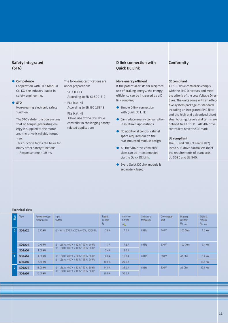
SD6 A04
SD6 A02
Type
SD6 A06
SD6 A14
SD6 A16
SD6 A24
SD6 A26
Braking resistor PBr max
Braking resistorRBr min
Overvoltage limit
Input voltage
Recommended motor power
0.75 kW
0.75 kW
1.50 kW
4.00 kW
7.50 kW
11.00 kW
15.00 kW
(L1-L3) 3 x 400 V, +32 %/-50 %, 50 Hz(L1-L3) 3 x 480 V, +10 %/-58 %, 60 Hz
(L1-L3) 3 x 400 V, +32 %/-50 %, 50 Hz(L1-L3) 3 x 480 V, +10 %/-58 %, 60 Hz
(L1-L3) 3 x 400 V, +32 %/-50 %, 50 Hz(L1-L3) 3 x 480 V, +10 %/-58 %, 60 Hz
(L1-N) 1 x 230 V +20 %/-40 %, 50/60 Hz 100 Ohm
47 Ohm830 V
22 Ohm830 V
6.4 kW
1.8 kW
6.4 kW
13.6 kW
29.1 kW
830 V 100 Ohm
440 V
Switching frequency
Maximum currentIma
Rated currentIN
8 kHz
8 kHz
8 kHz
8 kHz
Size
0
1
2
4.2 A
7.5 A
8.5 A
15.0 A
25.0 A
35.0 A
50.0 A
1.7 A
3.0 A
3.4 A
6.0 A
10.0 A
14.0 A
20.0 A
11
The following certifications are
under preparation:
– SIL3 (HF1)
According to EN 61800-5-2
– PLe (cat. 4)
According to EN ISO 13849
PLe (cat. 4)
Allows use of the SD6 drive
controller in challenging safety-
related applications
D link connection with Quick DC Link
More energy efficient
If the potential exists for reciprocal
use of braking energy, the energy
efficiency can be increased by a D
link coupling.
� Simple D link connection
with Quick DC Link.
� Can reduce energy consumption
in multiaxis applications.
� No additional control cabinet
space required due to the
rear-mounted module design
� All the SD6 drive controller
sizes can be interconnected
via the Quick DC Link.
� Every Quick DC Link module is
separately fused.
� Competence
Cooperation with PILZ GmbH &
Co. KG, the industry leader in
safety engineering.
� STO
Non-wearing electronic safety
function.
The STO safety function ensures
that no torque-generating en-
ergy is supplied to the motor
and the drive is reliably torque-
free.
This function forms the basis for
many other safety functions.
– Response time < 10 ms
Technical data
Safety integrated (ST6)
Conformity
CE compliant
All SD6 drive controllers comply
with the EMC Directives and meet
the criteria of the Low Voltage Direc-
tives. The units come with an effec-
tive system package as standard –
including an integrated EMC filter
and the high end galvanized sheet
steel housing. Levels and terms are
defined to IEC 1131. All SD6 drive
controllers have the CE mark.
UL compliant
The UL and cUL (“Canada UL”)
listed SD6 drive controllers meet
the requirements of standards
UL 508C and UL 840.

Service
The STÖBER service system compri-
ses 38 expert partners in Germany
and more than 80 companies in the
STÖBER SERVICE NETWORK world-
wide.
This service concept guarantees
local expertise and availability
when needed.
Note on the design of axesand drivesFor optimum axis design, it makes
sense to focus primarily on the gear
units or geared motors.
For an overall approach, use the
specific expertise of the STÖBER
application consultants.
Contact and advice:
In general, the service specialists
in the Pforzheim factory can be
reached at any time via a 24/7
service hotline.
When necessary, a problem can be
addressed immediately.
24/7 service hotline+49 180 5 786323
www.stober.com
Su
bje
ct t
o t
ech
nic
al
cha
ng
es
44
24
65
.00
K1
0
.00
0
02
/13
w
ww
.wa
st.d
e
STÖBER ANTRIEBSTECHNIK GmbH + Co. KG
Kieselbronner Str. 12
75177 PFORZHEIM
GERMANY
Phone +49 7231 582-0
Fax +49 7231 582-1000
www.stoeber.de
STOBER DRIVES LTD.CANNOCK WS12 2HAUNITED [email protected]
STOBER DRIVES, INC.MAYSVILLE, KY [email protected]
STÖBER ANTRIEBSTECHNIK GmbH4663 [email protected]
STOBER CHINABEIJING [email protected]
STOBER S.a.r.l.69300 CALUIRE ET [email protected]
STÖBER TRASMISSIONI S.r.l.20017 RHO (MI)[email protected]
STOBER Japan K. [email protected]
STOBER Singapore Pte. Ltd.SINGAPORE [email protected]
STÖBER Schweiz AG5453 [email protected]
As a system manufacturer,STÖBER offers completeand customized solutions Through the width and depth of its
product ranges, STÖBER can offer
uncompromising, individually cus-
tomized single source solutions.