matlab based simulation toolbox for the study and design of …mduartem/pdfs/caee2009.pdf ·...
TRANSCRIPT

Matlab Based SimulationToolbox for the Study andDesign of Induction Motor FOCSpeed DrivesA. COSTA,1 M. VILARAGUT,1 J. C. TRAVIESO-TORRES,2 M. DUARTE-MERMOUD,2 J. MUNOZ,1
I. YZNAGA1
1Centro de Investigaciones y Pruebas, Electroenergeticas, Facultad Electrica, Instituto Superior Politecnico ‘‘Jose Antonio,
Echeverrıa’’, Ciudad de la Habana, Cuba
2Departamento de Ingenierıa Electrica, Facultad de Ciencias Fısicas y Matematicas, Universidad de Chile, Santiago, Chile
Received 4 July 2007; accepted 19 October 2009
ABSTRACT: A new Matlab/Simulink based simulation toolbox for studying and designing induction motor
field oriented control schemes is proposed in this article. It has advantages over other previous works published
since it is modular, flexible, interactive, easy to use, and the results are closer to the experimental ones because it
takes into account real complex effects, such as: motor core saturation, parameter variations with the speed and
temperature, sensor signal digital processing, and inverter real voltage waveforms. These results has been
successfully applied in teaching undergraduate and graduate courses at the authors’ universities for building,
identification and characterization of diverse control schemes, analysis of parameter effects, and design and test
of new controllers for field oriented control schemes in induction motors. Beside the theoretical and
computational basis of the toolbox, simulation results of an indirect field oriented control current regulated pulse
width modulation scheme are presented in the article as example. �2009Wiley Periodicals, Inc. Comput Appl Eng
Educ; Published online in Wiley InterScience (www.interscience.wiley.com); DOI 10.1002/cae.20396
Keywords: AC drives; induction motor; dynamic simulation; field oriented control; direct torque control
INTRODUCTION
The increase of factory automation has been an important factor
in worldwide industrial progress during the past several decades.
Manufacturing lines in industrial plants typically involve one or
more variable speed motor drives that serve to power conveyor
belts, robot arms, paper mills, plastic and fiber processing lines,
just to name a few [1].
Prior to 1950s all such applications required the use of DC
motor drives. But, since the 1990s the use of AC drives started to
be preferred [1]. In general AC drives often feature several
advantages over their DC counterparts, such as: lower cost and
maintenance, smaller motor size, and improved reliability [1�3].
However, the AC drives control scheme is more complex.
There are three main schemes, the scalar V/f control, the field
oriented control (FOC) and the direct torque control (DTC), each
one with several variants. In these control schemes the use of an
inverter, controller blocks, and feedback signals processing is
involved [1�4]. Besides, the induction motor (IM) itself is not as
simple as the DC motor with separated field.
Perhaps, due to such complexity the study of AC drives is
usually performed on dynamic simulations, which involve a
lower cost than studies on a prototype but introduces some
simplifications. We have the case of the software SIMULINK1,
MATLAB1 which has a power system toolbox for the study of
electrical machines [5]. Several MATLAB based machine and AC
drives simulations are also proposed in Ref. [6].
On the other hand, due to budget constraints, laboratories
associated to certain courses in engineering curricula are being
left out. They are often replaced by powerful and more realistic
simulations. For instance, a virtual electric machine laboratory
for simulating asynchronous machines, including magnetic
saturation effects, is reported in [7,8] for teaching purposes.
A Matlab/Simulink realization of DC motor for
speed control purposes is presented in Ref. [9]. They include
different control methods such as field resistance, armature
voltage, armature resistance and feedback control for DC motor
drives.
Correspondence to M. Duarte-Mermoud ([email protected]).
� 2009 Wiley Periodicals Inc.
1
In Ref. [10] an educational software is presented for neuro-
fuzzy control of induction machines. The software has a flexible
structure and graphical user interface allowing easy changes on
neuro-fuzzy architecture and motor-load parameters.
A fully digital, real-time hardware-in-the-loop simulator on
PC-cluster, of electric systems and drives for research and
education purposes is presented in Ref. [11]. The simulator has
two main subsystems; software and hardware. The software
subsystem includes Matlab/Simulink environment, a Cþþcompiler and a real-time shell. The hardware subsystem includes
a data acquisition card, the control board, the sensors, and the
controlled motor.
In order to allow a deeper and more accurate study of AC
drives and machines, the main nonlinearities present in this
problem are considered in the simulation toolbox proposed in this
article. Seven modules named Set Points, Controllers, Trans-
formations, Inverters, Electro Mechanics, Sensors, and Miscella-
neous were developed, each one containing several blocks.
Beside, as example, six different FOC schemes ready to use were
included. In the simulation real complex effects are considered,
such as: motor core saturation, parameter variations with the
speed and temperature, sensor signal digital processing, and
inverter real voltage waveforms. Thus, compared to existing
simulation methods, the results obtained from the toolbox are
closer to the experimental ones, being also modular, flexible,
interactive, and easier to use. These conclusions were obtained
from teachers and students exposed to the proposed toolbox,
employed in several courses on AC drives and for research
purposes. Students and teachers were able to perform deeper
study of machines and drives, with faster simulations as
compared with previously used simulators, studying a larger
number of cases in the same period of time. Besides, the
characteristics of the toolbox developed here allowed students to
make more complex homework at their own.
Basic concepts of AC drives considered in the simulation
toolbox are exposed in the second section of this article. In
third section, the proposed Matlab/Simulink based simulation
toolbox is described. Its blocks consider the effects of the core
saturation and motor parameter variations with the speed and
temperature, as well as the effects of the feedback signal
processing and inverters actual voltage waveforms. An example
of AC drives built-in based on the proposed toolbox is studied in
fourth section, presenting the simulation results. Finally some
conclusions are drawn in fifth section.
BASIC CONCEPTS ON AC DRIVES
In this section we describe in a general form all the phenomena
involved in the developed toolbox. We explain, from theoretical
viewpoint, all the modules included in the toolbox for induction
motor studies. Based on these equations toolbox modules were
developed as explained in the third section.
Induction Motor Model (Electro Mechanics)
In this study we employ the model of the induction motor based
on references [1�6,12,13], including internal and external
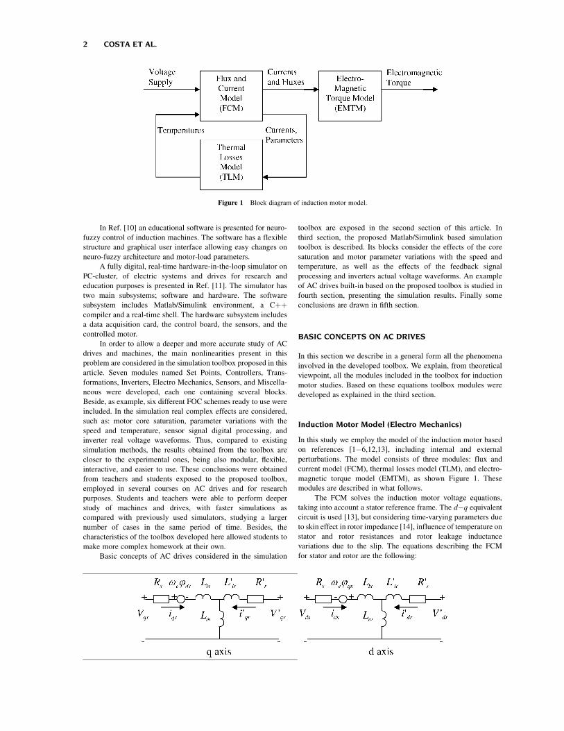
perturbations. The model consists of three modules: flux and
current model (FCM), thermal losses model (TLM), and electro-
magnetic torque model (EMTM), as shown Figure 1. These
modules are described in what follows.
The FCM solves the induction motor voltage equations,
taking into account a stator reference frame. The d�q equivalent
circuit is used [13], but considering time-varying parameters due
to skin effect in rotor impedance [14], influence of temperature on
stator and rotor resistances and rotor leakage inductance
variations due to the slip. The equations describing the FCM
for stator and rotor are the following:
Figure 1 Block diagram of induction motor model.
2 COSTA ET AL.

Vqs ¼ Rsiqs þdjqs
dtþ oejds
Vds ¼ Rsids þ djds
dt� oejqs
Vqr ¼ Rriqr þdjqr
dtþ oejdr
Vdr ¼ Rridr þ djdr
dtþ oejqr
ð2:1Þ
jqs ¼ Lsiqs þ Lmiqrjds ¼ Lsids þ Lmidrjqr ¼ Lriqr þ Lmiqsjdr ¼ Lridr þ LmidsLs ¼ Lls þ LmLr ¼ Llr þ Lm
ð2:2Þ
where R, L, oe, V, I, and j denote resistance, inductance,
electrical frequency, voltage, current, and flux respectively,
referred to rotor and stator on d�q axes. As mentioned before
parameters of these equations are time-varying taking into
account the following aspects.
* Stator winding resistance Rs depends upon its temperature
ys according to the following equation
Rs ¼ Rs0 1þ 0:004ðys � y0Þ½ � ð2:3Þ
where y0 is the environmental temperature.
* Rotor winding resistance Rr exhibits the same variation with
temperature as stator winding but also is a function of the
slip s, due to skin effect [14]. Its variation is given by the
following the relations:
Rr ¼ Rr0 1þ 0:004ðyr � y0Þ½ �; Rr0 ¼ K1 � K2
ffiffis
pð2:4Þ
* The rotor leakage inductance Llr varies with slip, due to skin
effect too [14], and can be calculated using the formula:
Llr ¼ K3 � K4
ffiffis
pð2:5Þ
Parameters K1, K2, K3, and K4 can be obtained from
manufacturer’s technical bulletin data or by means of no load
tests [15,16].
* The magnetizing inductance Lm is considered as a function
of the magnetizing Im current with a per unit typical curve
given by
Lmpu ¼ Km3I3m þ Km2I
2m þ Km1Im þ Km0 ð2:6Þ
In this equation, the coefficients depend upon the type of
motor [13].
Based on the knowledge of stator and rotor currents and the
value of the corresponding parameters, the TLM determines the
electrical losses in the motor stator, rotor and core. The electrical
analog thermal model, with lumped parameters, for stator, rotor
and core is shown in Figure 2. This module calculates the hot spot
temperature of the stator winding, magnetic core and rotor
winding, having as inputs the corresponding losses. Each node is
assigned to a thermal capacitance C and the heat flowing through
thermal nodes is passed through thermal resistances R
[15,17�19,24].
The corresponding thermal state space equations are:
dyadt
¼ 1Ca
Pa � Goaya þ Gasys½ �dysdt
¼ 1Cs
Ps þ Gsaya � Gssys þ Gsryr½ �dyrdt
¼ 1Cr
Pr þ Grsys � Grryr½ �ð2:7Þ
where Pa, Ps, Pr are the magnetic core, stator winding, and rotor
winding losses, respectively, Gaa ¼ 1=Raa þ 1=Rsa is the total
core thermal conductivity, Gas ¼ Gsa ¼ 1=Rsa is the mutual
thermal conductivity between magnetic core and stator winding,
Gss ¼ 1=Rsa þ 1=Rsr is the total stator winding thermal con-
ductivity, Gsr ¼ Grs ¼ 1=Rsr is the mutual thermal conductivity
between rotor winding and stator winding, Grr ¼ 1=Rrr þ 1=Rsr is
the total rotor winding thermal conductivity, and Ca, Cs, Cr are the
corresponding magnetic core, rotor winding, and stator winding
thermal capacitances.
The EMTM calculates the electromagnetic torque Te based
on the values of currents and flux linkages referred to the stator
[1�6,12,13] utilizing the expression given by
Te ¼ 1:5pðjdsiqs � jqsidsÞ ð2:8Þ
where p is the number of poles.
Finally, the well-known mechanical load model used in
Refs. [1�6,12] considers the electromagnetic torque Te and load
torque Tm as inputs, and the rotor angular speed or as output. The
equations are
dor
dt¼ 1
2HðTe � For � TmÞ
dydt
¼ or ð2:9Þ
where y is the rotor angular position.
Inverters
All AC drives feed the machine through an inverter whose
type depends on the speed drive scheme. There are two main
inverter types, the voltage source inverter (VSI) and the current
source inverter (CSI). The pulse width modulation (PWM) as VSI
and the current regulated PWM (CRPWM) as CSI are widely
used in FOC schemes with sinusoidal modulation. DTC instead
is known by the use of a voltage selection table feeding a
VSI [1�4].
The PWM is a VSI fed by the control voltages, usually with
sinusoidal waveform and then sinusoidal modulation. Different
current controllers can be designed as inner loop whose output
feeds the inverter [2]. Figure 3 shows the block diagram of a
PWM inverter used in a FOC scheme.
Conversely to VSI the CRPWM is a CSI and includes
the current controller. It is fed by the output of the outer speed
or flux controller loops. Here two main controllers are studied,
the hysteretic (CRPWMH) and the sub-oscillatory one
(CRPWMS) as it can be seen in Figures 4 and 5, respectively
[2]. The hysteretic method guarantees a good dynamic
behavior. It is simple, and it can be developed in an analog or
digital way.
On the other hand, the sub-oscillatory or stationary
controller is probably the most used method. The CRPWM with
sub-oscillatory controller is shown in Figure 5.
The inverter used by DTC schemes has two main blocks, a
look-up table and the inverter itself, as seen in Figure 6 and
Table 1 [2].
aP aC aaR
sPsC rC rrR
rP
saR srR
Figure 2 Induction motor thermal model.
MATLAB BASED SIMULATION TOOLBOX 3

Current Controllers 32?T
M3∼
Vcd
squ
sdu
au
cubu
Inverter
+
-
Clarke Transformation
Carrier
Figure 3 FOC with PWM inverter.
M3∼
Vcd
au
*ci
*bi
Inverter
*ai
32?TTorque &
Flux Controllers
*sqi
*sdi
+
-
Current Controller
Clarke Transformation
Figure 4 FOC with CRPWM and hysteretic controller as inverter.
oller as inverter.
M3∼
Vcd *ci
*bi
Inverter
*ai
32?TTorque &
Flux Controllers
*sqi
*sdi
Current Controller
Carrier
+
-
K +
-
Clarke transformation
Figure 5 FOC with CRPWM and sub-oscillatory controller as inverter.
4 COSTA ET AL.
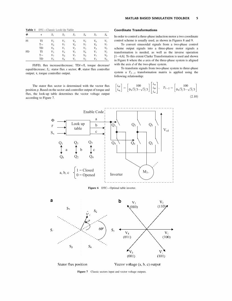
The stator flux sector is determined with the vector flux
position r. Based on the sector and controller output of torque andflux, the look-up table determines the vector voltage output
according to Figure 7.
Coordinate Transformations
In order to control a three-phase induction motor a two coordinate
control scheme is usually used, as shown in Figures 8 and 9.
To convert sinusoidal signals from a two-phase control
scheme output signals into a three-phase motor signals a
transformation is needed, as well as the inverse operation
[1�4,6]. To this extent Clarke Transformation is used and shown
in Figure 8 where the a axis of the three-phase system is aligned
with the axis d of the two-phase system.
To transform signals from two-phase system to three-phase
system a T2!3 transformation matrix is applied using the
following relationship:
isdisq
� �¼ 100
0ffiffiffi3
p=3�
ffiffiffi3
p=3
� � isaisbisc
24
35; T3!2 ¼
100
0ffiffiffi3
p=3�
ffiffiffi3
p=3
� �
ð2:10Þ
Table 1 DTC—Classic Look-Up Table
U s S1 S2 S3 S4 S5 S6
FI TI V2 V3 V4 V5 V6 V1
T¼ V0 V7 V0 V7 V0 V7
TD V6 V1 V2 V3 V4 V5
FD TI V3 V4 V5 V6 V1 V2
T¼ V7 V0 V7 V0 V7 V0
TD V5 V6 V1 V2 V3 V4
FI/FD, flux increase/decrease; TD/¼/I, torque decrease/
equal/decrease; Sx: stator flux x sector; U, stator flux controller
output; s, torque controller output.
Look up table
M3∼
Vcd
Inverter
Enable Code
a b c
Q6 Q2
Q1
Q4
Q3 Q5
Q1
Q6
Q3
Q2
Q5
Q4
a b c
a, b, c 1 = Closed 0 = Opened
Φτ
Sx
Figure 6 DTC—Optimal table inverter.
Figure 7 Classic sectors input and vector voltage outputs.
MATLAB BASED SIMULATION TOOLBOX 5

To transform from three-phase signals system into a two
phase one, the following transformation is applied
isaisbisc
24
35 ¼
10
�1=2ffiffiffi3
p=2
�1=2�ffiffiffi3
p=2
24
35 isd
isq
� �; T2!3 ¼
10
�1=2ffiffiffi3
p=2
�1=2�ffiffiffi3
p=2
24
35
ð2:11Þ
The Park transformation manages non-sinusoidal
signals and it is used in control schemes (e.g., FOC) where
amplitude and frequency of the sinusoidal wave are separately
controlled. This transformation handles two-phase signals, but
expressed in a different reference systems as shown in Figure 9
[1�4,6].
In Figure 9 rg is the position of the x�y reference system
with respect to the d�q system.
The coordinate shift from a rotating system to a fixed system
considers an ejrg transformation matrix and is given by
isd
isq
� �¼ ejrg
isx
isy
� �¼
cos rg �sen rgsen rg cos rg
" #isx
isy
� �;
ejrg ¼cos rg �sen rgsen rg cos rg
" # ð2:12Þ
whereas the coordinate shift from a fixed system to a rotational
system considers the inverse transformation e�jrg , which is the
following
isx
isy
� �¼ e�jrg
isd
isq
� �¼
cos rg �sen rgsen rg cos rg
" #�1isd
isq
� �;
isx
isy
� �¼
cos rg sen rg�sen rg cos rg
" #isd
isq
� � ð2:13Þ
Feedbacks Signal Processing
Sensor processing signal issues are also considered in the toolbox
developed for simulation. Hall-effect current sensors, and their
filters, and A/D converter quantization process, are taken into
account. For the incremental encoder case, as speed sensor,
filtering and quantization processes were considered.
There are several current control loop which are digital.
Others, like the one used in the CRPWM inverter, are developed
in an analog way. Digital loops involve the sampling and
quantization processes. Due to the small sampling period used
at present (from 40 to 300 ms), it is possible to neglect the
errors present when sampling frequency is small. However, since
we work with digital numbers which can only take integer
(discrete) values, the quantization process and its influence in the
system dynamics needs to be considered. Besides, the AC drives
use filters due to the inverter harmonics presence. Its presence
affects the dynamic behavior of the system, which is considered
here.
The current sensor could have three components, the sensor
itself, a filter and an A/D converter. The A/D conversion considers
the sampling, fixing and quantization processes. Usually, a
Butterworth filter is also considered to improve the wave quality
and to prevent aliasing effects considering a cutoff frequency. Its
transfer function is
GðsÞ ¼ Ksc
ð1=2pf0cÞ2s2 þ 1:41ð1=2pf0cÞsþ 1ð2:14Þ
where f0c is the filter cutoff frequency and Ksc its gain.
The A/D converter considers a gain and a quantizer to
achieve integer numbers. The converter gain is given by
Kconv ¼2nb�1
ucdð2:15Þ
where nb is the bits number and ucd is the converter maximum
tension [20�22].
To measure rotor speed an Incremental Encoder with three
pulse channels, is usually used. Two methods are considered by
the speed driver in order to obtain the speed from the pulse
signals; the frequencymeter and the periodmeter. The use of
the frequencymeter method is considered for high speeds. The
pulse number nps for the sampling period Tsv is determined by
nps ¼ Tsv
aor ð2:16Þ
where a is the corresponding angle for each pulse, determined by
a ¼ 2:p=nenc, with nenc the number of pulse encoder per
revolution. Finally we obtain
nps ¼ Tsvnenc
2por ð2:17Þ
Figure 8 Clarke transformation applied to stator current.
Figure 9 Park transformation applied to stator current.
6 COSTA ET AL.
Due to the dependences of the total angle and the angle a of
each pulse, this method introduces a quantification error which is
higher for higher speeds. Thus, in this case a Butterworth filter
(with cutoff frequency f0s) is also considered in order to improve
the wave quality [20�22].
The use of the periodmeter method [20�22] is considered
for low speeds. A high frequency clock is used to determine rotor
speed through the expression
or ¼a
Tencð2:18Þ
where Tenc is sampling period of the clock determined by
Tenc ¼ nhf=fhf , with nhf being the clock pulse number of
frequency fhf. From these equations, the encoder speed output is
determined as follows:
nhf ¼2pfhfnenc
or ð2:19Þ
Finally, the speed of change from periodmeter to frequen-
cymeter is denoted as wc.
MATLAB BASED SIMULATION TOOLBOXDESCRIPTION
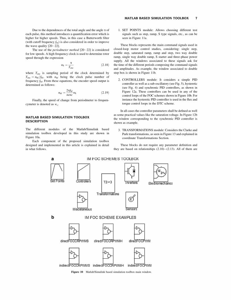
The different modules of the Matlab/Simulink based
simulation toolbox developed in this study are shown in
Figure 10a.
Each component of the proposed simulation toolbox
designed and implemented in this article is explained in detail
in what follows.
1. SET POINTS module: Allows choosing different test
signals such as step, ramp, S type signals, etc., as can be
seen in Figure 11a.
These blocks represents the main command signals used in
closed-loop motor control studies, considering: single step,
double step, saturated ramp, ramp and step, two way double
ramp, single way double ramp, S starter and three-phase power
supply. All the windows associated to these signals ask for
the time of the different periods composing the command signals
and amplitudes. As example, the window associated to double
step box is shown in Figure 11b.
2. CONTROLLERS module: It considers a simple PID
controller as well as a sub-oscillatory (see Fig. 5), hysteretic
(see Fig. 4) and synchronic PID controllers, as shown in
Figure 12a. These controllers can be used in any of the
control loops of the FOC schemes shown in Figure 10b. For
instance the hysteretic PID controller is used in the flux and
torque control loops in the DTC scheme.
In all cases the controller parameters shall be defined as well
as some practical values like the saturation voltage. In Figure 12b
the window corresponding to the synchronic PID controller is
shown as example.
3. TRANSFORMATIONS module: Considers the Clarke and
Park transformations, as seen in Figure 13 and explained in
coordinate Transformations Section.
These blocks do not require any parameter definition and
they are based on relationships (2.10)�(2.13). All of them are
Figure 10 Matlab/Simulink based simulation toolbox main window.
MATLAB BASED SIMULATION TOOLBOX 7

fixed matrices, which in the case of the Park transformation
depends on the rho value (rg).
4. INVERTERS module: It is shown in Figure 14 and
simulates the different types of PWM inverters as
explained in Inverters Section.
These blocks consider the power electronic converters that
usually feed the induction motor in vector control systems. Each
window needs the definition of the commutation frequency,
the regulator parameters and the DC voltage bus. In Figure 14b
the window associated to PWM inverter is shown as illustrative
example.
5. ELECTROMECHANICS module: It is exposed in
Figure 15a.
The Simple Load module simulates the mechanical load on
the motor axis. The Load with Perturbation module allows the
possibility of including load disturbances at any instant of the
simulation.
The input signals of the IM block are the three-phase
voltages, ua, ub, uc, the magnetizing current imr (in order to
determine the magnetizing inductance), the rotor speed or and the
stator revolving field speed os. The rotor speed comes from
the mechanical load modules and the rest of the inputs from the
Figure 11 SET POINTS module. (a) General view. (b) Double step data input window.
8 COSTA ET AL.

control system. The IM input window asks for the motor
parameters and the mechanical load for the total inertia. The
outputs are the three currents ia, ib, ic, and the motor torque Mem,
which is the input to the mechanical load module. A module
considering the possibility of load disturbances is also included,
asking for the load mechanical characteristic and the time for the
application of the disturbance.
As additional information Figure 15b shows the window
corresponding to IM module.
6. SENSORS module: It contains the simulation of the
current acquisition system (including the filters), the
encoder and the gearbox for simulating the mechanical
transmission. There are three blocks involved as seen in
Figure 16a; the encoder sensor block (for simulating the
inherent characteristic of this transducer such as the
quantization error and its pulsed waveform), the current
sensor block (that includes the filter and the A/D converter)
and the gearbox position module (including the speed to
position conversion).
The encoder window ask for the number of pulses per
revolution, the cutoff frequency of the encoder filter, the
periodmeter parameters, the sampling period and the processor
clock frequency. The current data acquisition system needs the A/
D converter analog voltage and number of bits and the filter
frequency (see Feedbacks Signal Processing Section). The
gearbox position block only asks for the gearbox ratio.
Figure 16b illustrates the window associated to the encode sensor
module as example.
Figure 12 CONTROLLERS module. (a) General view. (b) PID synchronic controller data input window.
MATLAB BASED SIMULATION TOOLBOX 9

7. MISCELANEOUS module: Simulates the flux level
selector, and the slip and angle calculation for the indirect
and direct field oriented control schemes respectively (see
Fig. 17a).
The Direct FOC block calculates the rotor flux vector angle.
Its inputs are the currents ia, ib, and the rotor speed or. The outputs
are the reference frame angle rg, the estimated magnetizing
current imr, the estimated electromagnetic torque Mem, and
the frequency os. It asks for the estimated rotor time constant Tr,
the torque constant and the number of poles of the motor. The
Indirect FOC block calculates the slip os for the indirect
field oriented vector based upon the two current components
isx, isy and the rotor speed or. It asks for the estimated rotor time
constant and the number of poles of the motor. The Flux Selector
block is used for choosing the constant torque operation zone or
the constant power operation zone. It needs the nominal motor
speed and the nominal excitation current. In Figure 17b the
window corresponding to Flux Selector module is shown as
example.
Based on the seven modules already explained different
control schemes can be implemented for the IM. The toolbox
developed include six different FOC schemes for IM (see
Fig. 10b) that can be chosen by the user as ready to use examples
or as a starting point to develop new control strategies, such as
DTC. In the next section only one of these FOC scheme is
simulated in detail to see how the toolbox works in general.
CASE STUDY
Simulation results of a speed drive control based on indirect FOC
CRPWMS scheme are reported in this section. The following
blocks were adjusted with the values of the parameters indicated
in what follows.
* Set Point: A speed reference type Up-Down Ramp of
amplitudes ½0 180 180 0� rad/s and instants of time
½0 25 35 50� s was used in the simulation.
Figure 13 TRANSFORMATIONS module. Park and Clarke transforma-
tions.
Figure 14 INVERTERS module. (a) General view. (b) PWM inverter data input window.
10 COSTA ET AL.

* Simple Load: Electromechanic torque vector of
½23 23 23�Nm, speed vector of ½0 80 200� rad/s, load
inertia of 2.6 kgm2, motor inertia of 0.79 kgm2, and zero
active torque load and initial rotor speed.* Induction Motor: Four poles, rotor dependence parameters
(K1, K2, K3, and K4) of ½0:0825 0:0144 0:000344 0:000135�,magnetizing inductance of 0.0205 H, stator leakage
inductance of 0.0006745H, stator resistance of 0.0385O,758C of running temperature for the stator and rotor, 220/
H3 nominal voltage, and 60Hz.
* CRPWMS: proportional gain 50, integral gain 10, saturation
voltage of 10V, CD bus voltage of 295V, 2kHz frequency for
the triangle wave with an amplitude of 10V.* Indirect FOC: with a rotor time constant Tr of 0.155 and
four poles.* Flux Selector: with 182.5 rad/s nominal angular rotor speed,
and a nominal magnetizing current of 22A.* Matlab Simulation Parameters: 50 s stop time, 0.002 fixed
step calculation method of ODE5 (Dormand-Prince) in
automatic mode.
Figure 15 ELECTROMECHANICS module. (a) General view. (b) IM data input window.
Figure 16 SENSORS module. (a) General view. (b) Encoder sensor data input window.
MATLAB BASED SIMULATION TOOLBOX 11
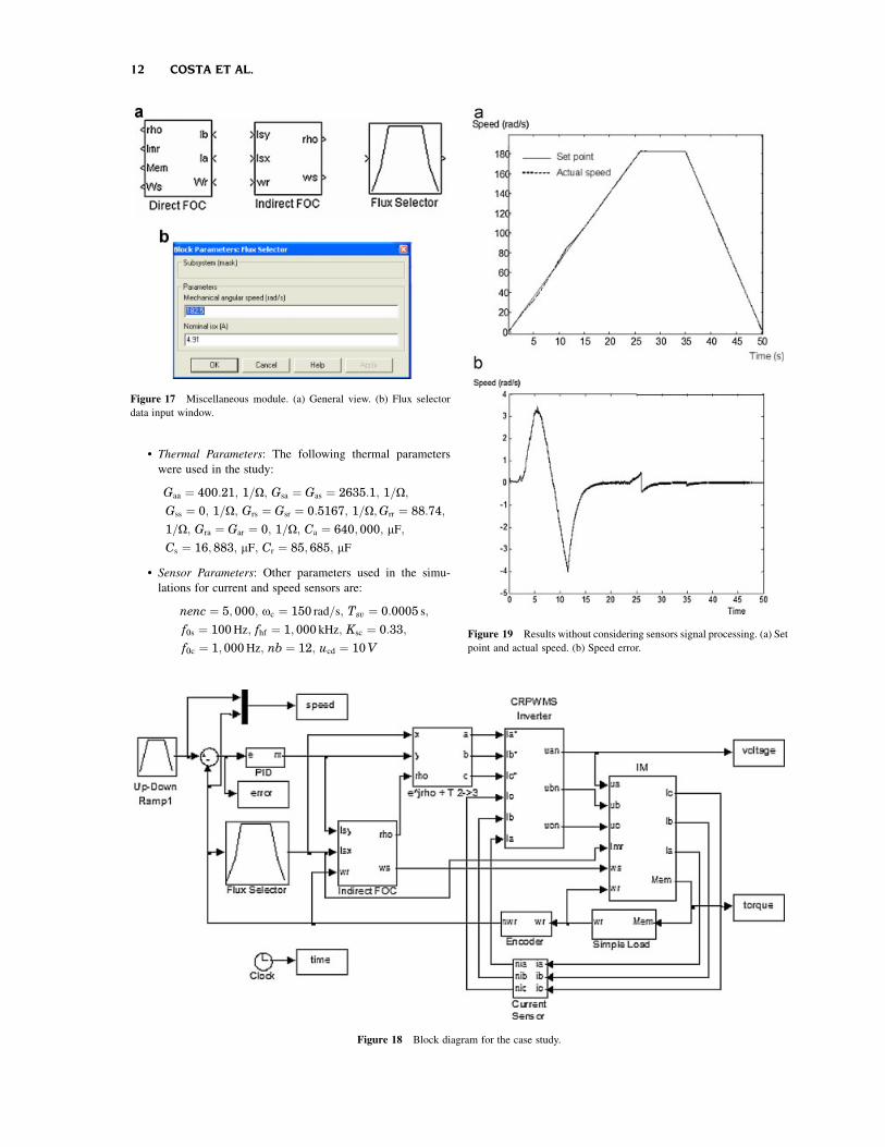
* Thermal Parameters: The following thermal parameters
were used in the study:
Gaa ¼ 400:21; 1=O; Gsa ¼ Gas ¼ 2635:1; 1=O;
Gss ¼ 0; 1=O; Grs ¼ Gsr ¼ 0:5167; 1=O;Grr ¼ 88:74;
1=O; Gra ¼ Gar ¼ 0; 1=O; Ca ¼ 640;000; mF;
Cs ¼ 16;883; mF; Cr ¼ 85;685; mF
* Sensor Parameters: Other parameters used in the simu-
lations for current and speed sensors are:
nenc ¼ 5; 000; oc ¼ 150 rad=s; Tsv ¼ 0:0005 s;
f0s ¼ 100Hz; fhf ¼ 1; 000 kHz; Ksc ¼ 0:33;
f0c ¼ 1;000Hz; nb ¼ 12; ucd ¼ 10V
Figure 17 Miscellaneous module. (a) General view. (b) Flux selector
data input window.
Figure 18 Block diagram for the case study.
Figure 19 Results without considering sensors signal processing. (a) Set
point and actual speed. (b) Speed error.
12 COSTA ET AL.
In Figure 18 is shown the block diagram corresponding to
the case studied in this article.
The speed and excitation controller were designed with the
method explained in Ref. [23], the current limits and inverter
parameters utilized and the motion sensor and current data
acquisition system were designed as in Refs. [20,22]. The
simulation program was implemented with and without consid-
ering the effects of the speed sensor and the current data
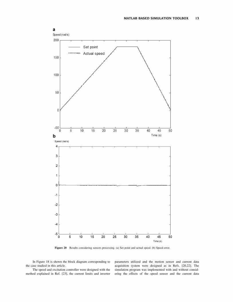
Figure 20 Results considering sensors processing. (a) Set point and actual speed. (b) Speed error.
MATLAB BASED SIMULATION TOOLBOX 13

acquisition system. In Figure 19a the comparison between the
speed reference and the speed response without considering
the sensors signal processing is depicted. In Figure 20a the same
comparison is done but considering now the sensors signal
processing. Figures 19b and 20b show the speed error in both
cases.
Figures 21 and 22 show the evolution of current and voltage
on phase a, with and without considering the sensor processing
effects. A time interval from 30 to 30.1 s was chosen to show in
detail the waveforms obtained from the simulations considering
all the effects already described. From these figures it can be seen
that current and voltage waveforms, with and without considering
Figure 21 Phase a current. (a) Without considering the sensors signal processing. (b) Considering the sensors signal
processing.
14 COSTA ET AL.
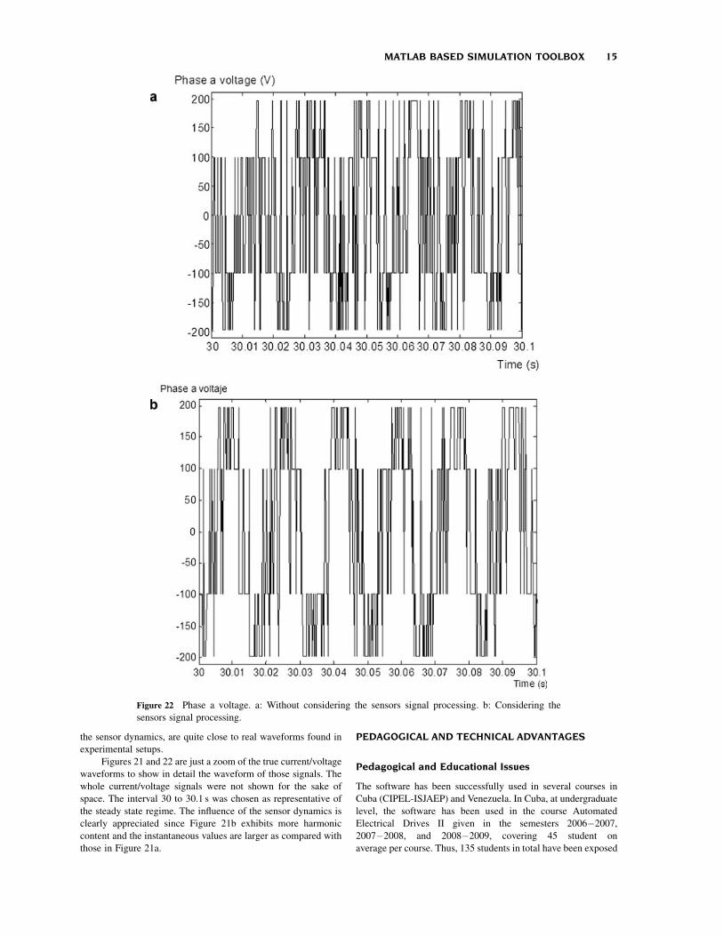
the sensor dynamics, are quite close to real waveforms found in
experimental setups.
Figures 21 and 22 are just a zoom of the true current/voltage
waveforms to show in detail the waveform of those signals. The
whole current/voltage signals were not shown for the sake of
space. The interval 30 to 30.1 s was chosen as representative of
the steady state regime. The influence of the sensor dynamics is
clearly appreciated since Figure 21b exhibits more harmonic
content and the instantaneous values are larger as compared with
those in Figure 21a.
PEDAGOGICAL AND TECHNICAL ADVANTAGES
Pedagogical and Educational Issues
The software has been successfully used in several courses in
Cuba (CIPEL-ISJAEP) and Venezuela. In Cuba, at undergraduate
level, the software has been used in the course Automated
Electrical Drives II given in the semesters 2006�2007,
2007�2008, and 2008�2009, covering 45 student on
average per course. Thus, 135 students in total have been exposed
Figure 22 Phase a voltage. a: Without considering the sensors signal processing. b: Considering the
sensors signal processing.
MATLAB BASED SIMULATION TOOLBOX 15
to the software to develop laboratory work associated to the
course.
At graduate level (master degree program), the software was
used in the course Control of Positioning Systems during
the years 2007 and 2008, covering 36 students in all. The
software was also used in the development of an E.E. Master
Thesis in 2006.
In Venezuela, the software is being used at graduate level in
laboratory courses as well as E.E. Theses, as part of the Master
degree program given by CIPEL in three Venezuelan universities.
Thirty students have been exposed to the software during
2007�2008 period.
Compared to existing simulation methods, the results
obtained from the toolbox developed here are closer to the
experimental ones, being also modular, flexible, interactive, and
easier to use. These conclusions were obtained from teachers and
students exposed to the proposed toolbox, employed in several
courses on AC drives and for research purposes. Students and
teachers were able to perform deeper studies of machines and
drives, with faster simulations as compared with previously
used simulators, studying a larger number of cases in the same
period of time. Besides, the characteristics of the toolbox
presented here allowed students to make more complex home-
work at their own.
Technical Advantages
The current Matlab/Simulink software includes a toolbox for
electrical drives containing limited models for electrical
machines and control components since they are mainly linear
and do not consider nonlinear phenomena whose influence in
machine’s behavior may become important. Some of these
phenomena are indeed considered in the proposed toolbox.
One of the phenomena taken into account here is the rotor
inductance and resistance variations due to skin effect. This effect
exists and it is intentionally emphasized by manufacturers to
increase the starting resistance (improving the starting torque)
and to lower the resistance during the normal operation
(achieving high efficiency). Something similar is obtained for
the rotor inductance. The effects are not relevant in steady state
regime studies but they make an important difference (produces
large errors) while studying transient periods, for example, in
control of electrical machines under FOC or other control
schemes.
If rotor resistance is considered constant and equal to the
nominal value the starting torque results much lower than the true
one and it may happen that under high load torque the motor is
not able to start in the simulation. On the contrary, if rotor
resistance is considered constant and equal to the starting value
the steady state regime speed will be lesser than the real one. The
proposed software considers in a simple fashion this variation since
the rotor resistance is made a function of the square root of slip.
Another improvement of the presented toolbox has to do
with the encoder to measure the speed. This device is based on
counting the number of pulses that can take only integer values.
Different counting methods give raise to different quantization
errors that may be important when determining the dynamical
behavior of the control system. The quantization error and the
sampling period are considered in the proposed toolbox.
Besides, the nonlinear nature of power converters, partic-
ularly the inverters, is also taken into account in the proposed
software. This makes the simulation process faster.
Finally, as far as evidence of the toolbox advantages is
concerned, we would like to mention that from Figure 19b an
error different from zero in the transient response and during the
stabilization is observed. This is due to field orientation loss. In
fact, notice that the orientation block has a fixed rotor time
constant Tr of 0.155, which is different from the true rotor time
constant which varies due to speed and temperature variations of
Lr and Rr, respectively. This error is not observed in Figure 20b
when these variations are really considered.
CONCLUSIONS
A new Matlab based simulation toolbox for the study and design
of IM FOC schemes was presented in this article. The system is
modular, flexible, interactive and easier to use. The obtained
results are closer to the experimental ones since it considers the
effects of core saturation and parameter variations of the
induction motor due to the speed and temperature, as well as
the effects of the sensor signal digital processing and inverters
real voltage waveforms. As example, simulations results of a
FOC CRPWMS scheme using the developed toolbox were
presented, from which the advantages of the proposed toolbox
can be appreciated.
In the near future, additional controllers’ blocks will be
included considering: synchronous current control, fuzzy logic,
neural network, sliding mode and adaptive passivity based
controllers. The design of an OBSERVER module is also
currently being developed.
ACKNOWLEDGMENTS
The results reported in this article have been supported by
CITMA-CONICYT through grant No. 2003-4-064.
REFERENCES
[1] B. K. Bose, Power electronics and variable frequency drives. IEEE
Press Marketing, New York, 1997.
[2] B. K. Bose, Modern power electronics and AC drives. Prentice Hall
PTR, Upper Saddle River, NJ, 2002.
[3] P. Vas, Sensorless vector and direct torque control. Oxford
University Press, New York, 1998.
[4] P. Vas, Electrical machines and drive. A space-vector theory
approach. Oxford University Press, New York, 1992.
[5] TransEnergie Technologies, under sublicense from Hydro-Quebec,
and MathWorks,Inc., Copyright 1997-2002, ‘‘Asynchronous
machine, Model the dynamics of a three-phase asynchronous
machine, also known as an induction machine’’, Library Machines,
from the SimPowerSystems. MATLAB, version 6.5.0.180913a
release 13, June 18, 2002.
[6] C. M. Ong, Dynamic simulation of electric machinery, using
Matlab/Simulink. Prentice Hall PTR, New Jersey, 1998.
[7] E. Tanyildizi and A. Orhan, Avirtual electric machine laboratory for
effect of saturation of the asynchronous machine application,
Comput Appl Eng Educ 17 (2009), 422�428.
[8] E. Tanyildizi and A. Orhan, A virtual electric machine laboratory
for synchronous machine application, Comput Appl Eng Educ
17 (2009), 187�195.
[9] S. Ayasun and G. Karbeyaz, DC motor speed control methods using
MATLAB/Simulink and their integration into undergraduate
16 COSTA ET AL.

electric machinery courses, Comput Appl Eng Educ 15 (2007),
347�354.
[10] M. Gokbulut, C. Bal, and B. Dandil, A virtual electrical drive
control laboratory: Neuro-fuzzy control of induction motors’,
Comput Appl Eng Educ 14 (2006), 211�221.
[11] O. A. Mohammed and N. Y. Abed, Real-time simulation of electric
machine drives with hardware-in-the-loop, COMPEL: Int J Comput
Math Electr Electron Eng 27 (2008), 929�938.
[12] P. Vas, Parameter estimation, condition monitoring, and diagnosis of
electrical machines. Oxford University Press, New York, 1993.
[13] P. Kovacs, Transient phenomena on electrical machines. Elsevier
New York, 1984.
[14] M. P. Kostenko and L. Piotrovsky, Electrical machines, I and II. Mir
Publishers, Moscow, 1976, pp. 531�557.
[15] E. Ruppert Filho and E. Avolio, Squirrel-cage induction-motor
dynamics simulation using an electrical and thermal mathematical
model based on manufacturer technical bulletins data and on technical
standard statements, Int J Power Energy Syst 14 (1994), 13�16.
[16] N. Galan, G. Ciumbulea, and S. Deleanu, Ratings and parameters of
induction motors equivalent schemes, Proc ICEM98 1 (1998),
239�242.
[17] S. Zochol, E. Scweitzer, and A. Aliaga-Zegarra, Thermal protection
of induction motors enhanced by interactive electrical and thermal
models, IEEE Trans Power Apparatus Syst 103 (1984), 1749�1755.
[18] A. H. Eltom and N. S. Moharari, Motor temperature estimation
incorporating dynamic rotor impedance. IEEE PES Summer
Meeting, Minneapolis, 1990, pp. 107�113.
[19] P. H. Mellor, D. Roberts, and D. R. Turner, Lumped parameter
thermal model for electrical machines of TEFC design. IEE Proc B
138 (1991), 205�218.
[20] F. Briz del Blanco, Control vectorial del motor de induccion con
identificacion y adaptacion a los parametros de la carga. Ph.D.
Thesis, Universidad de Oviedo, 1997.
[21] M. V. Nuez-Amador, Simulacion y control del motor de induccion
por campo orientado. Ph.D. Thesis, CIPEL, Instituto Superior
Politecnico Jose Antonio Echeverrıa ISPJAE, Ciudad de la Habana,
1998.
[22] F. Briz, J. A. Cancelas, and A. Diez, Speed measurement using
rotary encoders for high performance AC drives, Proceedings of the
20th International Conference on Industrial Electronics, Control
and Instrumentation, IECON 94, 5�9 September 1994. Vol. 1,
pp. 538�542.
[23] W. Grantham and T. Vincent, Modern control systems: Analysis and
design. John Willey and Sons, U.K. 1993.
[24] A. Costa and X. M. Lopez-Fernandez, Dynamic induction motor
model considering skin effect and thermal performance. Proceed-
ings of the International Conference on Electrical Machines, ICEM
2002, Bruges, Belgium.
BIOGRAPHIES
Angel Costa has been an Electric Machines
and Drives professor since 1966, investigating
the development of industrial drives for Cuban
industry. He has written many papers and
books related to these themes and participated
in many international and national confer-
ences. He obtained the PhD degree from the
Polytechnic Institute of Havana ‘‘Jose Anto-
nio Echeverria’’ in 1987. He was a member of
the Cuban Commission for the Development of Wind Energy. He has
participated in many international projects and managed some of
them. He is currently participating in the project for the introduction
of Distributed Generation in the city of Luanda, Angola. His research
interests are in the areas of Wind Energy, Electrical Drives and
Distributed Generation development.
Miriam Vilaragut has been an Electric
Machines and Drives professor since 1982,
investigating in the introduction of Neural
Networks in Electric Power Systems and
Generators. She obtained the PhD degree
from the Polytechnic Institute of Havana
‘‘Jose Antonio Echeverr��a’’ in 2002 with a
special Cuban award for developing a system,
based in Neural Network for the diagnosis of
incipient faults in Synchronous Generator She has written many
papers for Cuban and international journals and publications. She is
currently the Director of the Cuban ‘‘Centro de Investigaciones
Electroenergeticas (CIPEL). Her research interests are in the areas of
Electric Drives and Neural Network applications in Electrical
Engineering.
Juan C. Travieso-Torres has 14 years of
professional experience, including more than
9 years of teaching and research activities
developed in parallel with his primary job. He
is Doctor in Automatic Control, Master in
Electrical Engineering, Electrical Engineer,
and Bachelor in Electronics. He has been
project manager in mining engineering proj-
ects with a budget between 50 and 130millions
dollars for BRASS Chile S.A; a corporative subject matter expert for
Fluor, in the areas of DCS/PCS, control strategies, and variable speed
drives; an Instrumentation and Control system Leader for Fluor and
the Mining Company ‘‘Dona Ines de Collahuasi’’; and an electrical/
electronic maintainer.
Manuel A. Duarte-Mermoud received the
degree of Civil Electrical Engineering from the
University of Chile in 1977 and M.Sc., M.Phil.,
and Ph.D. degrees, all in electrical engineering,
from Yale University in 1985, 1986 and 1988,
respectively. From 1977 to 1979, he worked as
Field Engineer at Santiago Subway. In 1979 he
joined the Electrical Engineering Department
of University of Chile, where he is currently
Professor. His main research interests are in robust adaptive control
(linear and nonlinear systems), system identification, signal process-
ing and pattern recognition. He is focused on applications to mining
and wine industry, sensory systems and electrical machines and
drives. Dr. Duarte-Mermoud is a member of the IEEE and IFAC. He is
past Treasurer and past President of ACCA, the Chilean National
Member Organization of IFAC, and past Vice-President of the IEEE-
Chile.
MATLAB BASED SIMULATION TOOLBOX 17

Javier Munoz has been an Electric Drives
and Automatic Control professor, since 2001
investigating in the development of Switched
Reluctance Conmutated Drives being applied
in Cuban industry. He obtained the M.Sc.
Degree from the Cuban ‘‘Centro de Inves-
tigaciones Electroenergeticas (CIPEL) in
2005 and is working on his PhD dissertation
on developing a sensorless SRC drive.
Ivonne Yznaga has been an Electric Drives
professor since 2002, investigating in the
simulation, analysis and development of differ-
ent types of fault tolerant Electric Drives
utilizing Artificial Intelligence. She obtained
the Ph.D. degree from the Zhejiang University,
Hangzhou, China in 2008. She is currently an
Electrical Machines and Drives professor at the
Cuban ‘‘Centro de Investigaciones Electro-
energeticas (CIPEL). Her research interests are in the area of
Artificial Intelligence applications in Electric Drives and Machines.
18 COSTA ET AL.