material properties and casting of test...
TRANSCRIPT

66
Chapter-3
MATERIAL PROPERTIES
AND CASTING OF TEST
SPECIMEN

67
CHAPTER 3: MATERIAL PROPERTIES AND CASTING OF TEST
SPECIMEN
3.1 GENERAL 68-68
3.2 OVERVIEW OF EXPERIMENTAL PROGRAMME 68-69
3.3 MATERIALS USED AND THEIR PROPERTIES 70-70
3.3.1 Cement 70-70
3.3.2 Fine Aggregate 71-71
3.3.3 Coarse Aggregate 72-73
3.3.4 Silica Fume 73-73
3.3.5 Water 73-74
3.3.6 Superplasticizer 75-75
3.3.7 Reinforcement 75-75
3.4 MIX DESIGN 75-77
3.5 CASTING OF SPECIMEN 77-82
3.6 MECHANICAL PROPERTIES 82-87
3.7 SUMMARY 87-89

68
CHAPTER-3
MATERIAL PROPERTIES AND CASTING OF TEST
SPECIMEN
3.1 GENERAL
This chapter deals with the experimental program for the
proposed research work. The materials used in this research are
cement, coarse aggregate, fine aggregate, silica fume, superplasticizer,
water and high yield strength deformed bars as reinforcement. This
chapter deals the testing of materials used, mix design, dosage of
mineral and chemical admixtures and casting of specimens.
3.2 OVERVIEW OF EXPERIMENTAL PROGRAMME
The experimental program is divided in to five stages. The first
stage deals with an assessment of material properties used in the
research work. The second stage is associated about mix design of
concrete and based on the results obtained in the first stage. The third
stage is associated about the casting of cylinders, cubes and slab
specimens that are used in the research based on second stage mix
design. The fourth stage deals with the testing of cube and cylinder
specimens. The fifth stage is testing of slab specimens under flexure,
punching shear with simply supported and fixed edge conditions and
slab specimens under impact loading with all edges fixed condition.
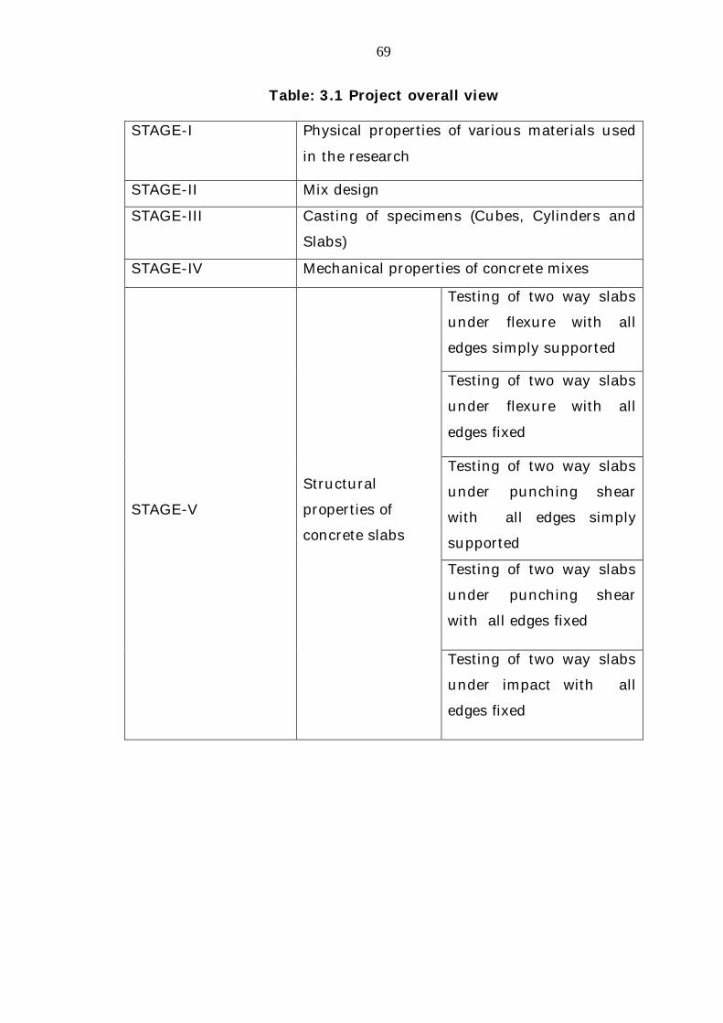
Table 3.1 outlines the stages of the research work.
69
Table: 3.1 Project overall view
STAGE-I Physical properties of various materials used
in the research
STAGE-II Mix design
STAGE-III Casting of specimens (Cubes, Cylinders and
Slabs)
STAGE-IV Mechanical properties of concrete mixes
STAGE-V
Structural
properties of
concrete slabs
Testing of two way slabs
under flexure with all
edges simply supported
Testing of two way slabs
under flexure with all
edges fixed
Testing of two way slabs
under punching shear
with all edges simply
supported
Testing of two way slabs
under punching shear
with all edges fixed
Testing of two way slabs
under impact with all
edges fixed

70
3.3 MATERIALS USED AND THEIR PROPORTIES
Various tests on materials like, cement, fine aggregate, coarse
aggregate and water have been conducted to confirm their suitability
to use in concrete making as per the procedures laid down in IS
Codes. It is observed that all the materials satisfy the relevant
provisions of IS Code of practice. The results of various tests
conducted on raw materials are presented in this chapter. High
Performance Concrete (HPC) and Reinforced Cement Concrete (RCC)
slabs elements are produced in the laboratory using these materials to
evaluate the behaviour of HPC and RCC slabs.
3.3.1 Cement
Ordinary Portland cement of 43 grade of Ultra-tech Cement
confirming to IS: 8112-198954 standards was used. The specific
gravity, normal consistency, initial and final setting times and
compressive strength of cement tests had been carried out and the
results are presented in Table 3.2.
Table: 3.2 Test results of cement
S.No Test Experimental values
Suggested values as per IS 8112-198954 Specifications
1 Fineness of Cement By using blains specific surface area (m2/kg)
320
225
2 Specific Gravity 3.14
3 Normal Consistency (%) 32
4 Setting time (minutes)
Initial Final
105 375
Min≥ 30 minutes Max ≤ 600 minutes
5 Compressive Strength (N/ mm2)
3 days 7 days 28 days
30.00 36.00
58.00
23.00 33.00
43.00

71
3.3.2 Fine Aggregate
The locally available sand confirming to Zone-II grade of Table 4
of IS 383-197050 has been used as Fine Aggregate. Tests have been
carried out as per the procedure given in IS Codes and the results are
tabulated in Table 3.3 and 3.4.
Table: 3.3 Sieve analysis of fine aggregate
Sl.No I. S Sieve Designation
Weight retained
(gms)
% of weight
retained
Cumulative % of weight retained
% of Passing
1 10 mm 0.00 0.00 0.00 100
2 4.75 mm 55.00 5.50 5.50 94.50
3 2.36 mm 90.00 9.00 14.50 85.50
4 1.18 mm 143.00 14.30 28.80 71.20
5 600 µ 204.00 20.40 49.20 50.80
6 300 µ 312.00 31.20 80.40 19.60
7 150 µ 178.00 17.80 98.20 1.80
8 Pan 18.00 1.8 100.00 0.00
Fineness Modulus = 2.711 Total = 271.10
Table: 3.4 Physical properties of fine aggregate
S.No Property Value
1 Specific Gravity 2.62
2 Fineness Modulus 2.711
3 Grading Zone – II

72
3.3.3 Coarse Aggregate
The locally available crushed granite has been used as coarse
aggregate in this investigation. For the mix design of HPC and normal
concrete it is necessary to know the properties of material i.e., Sieve
analysis, Specific gravity, density and water absorption. The tests
have been carried out as per the procedure given in IS Codes and the
results are presented in Table 3.5, 3.6 and 3.7.
Table: 3.5 Sieve analysis of 20 mm coarse aggregate
Sl. No I.S. Sieve Designation
Weight retained
(gms)
% of weight
retained
Cumulative % of weight
retained % of
Passing
1 40 mm 0.00 0.00 0.00 100
2 20 mm 324.00 3.24 3.24 96.76
3 10 mm 8416.00 84.16 87.4 12.60
4 4.75 mm 1224.00 12.24 99.64 0.36
5 2.36 mm --- --- --- ---
Table: 3.6 Sieve analysis of 12.5 mm coarse aggregate
Sl. No
I.S. Sieve Designation
Weight retained
(gms)
% of weight
retained
Cumulative % of weight
retained % of
Passing
1 40 mm 0.00 0.00 0.00 100
2 20 mm 0.00 0.00 0.00 100
3 12.5 mm 192.00 3.84 3.84 96.16
4 10.00 mm 2896.00 57.92 61.76 38.24
5 4.75 mm 1694.00 33.88 95.64 4.36
6 2.36 mm --- --- --- ---

73
Table: 3.7 Physical properties of coarse aggregate
Sl.No Property Value
1 Specific Gravity 2.66
2 Bulk Density Kg/m3)
Loose
Compacted
1320
1535
3 Water absorption (%) 0.52
3.3.4 Silica Fume
Silica fume is a byproduct of producing silicon metal or
ferrosilicon alloys. One of the most beneficial use of silica fume in
concrete is of its chemical and physical properties, it is a very reactive
pozzolan. Elkam brand silica fume is used for the investigation and
the properties supplied by the supplier are, colour appears to be Gray,
Bulk density is 500 Kg/m3, specific surface are 15-30 m2/gm and
average particle size is 0.2micron.
3.3.5 Water
Water is the key ingredient in producing concrete clean potable
fresh water which is free from concentration of acid and organic
substances has been used for mixing and curing the concrete. The
results of various tests are presented in Table 3.8.

74
Table: 3.8 Physical properties of water
S.No Parameter Amount
1 pH at 250 7.58
2 Taste Agreeable
3 Appearance Normal
4 Turbidity (NT Units) 7.92
5 Colour (Hazen Units) 3.2
6 Hardness (mg/l) 400
7 Sulphates (mg/l) 329
8 Chlorides (mg/l) 72
9 Odour (Ton) 3.02
10 Suspended Solids 135
11 Total Dissolved Solids 212
12 Total hardness as Ca Co3 112
13 Calcium as Ca 14
14 Magnesium as Mg 42
15 Carbonate Hardness as Ca Co3 40
16 Non-Carbonate Hardness as Ca Co3 95
17 Bi-Carbonate Hardness as Ca Co3 12
18 Carbonate as Co3 32
19 Bi-Carbonate as H Co3 27
20 Chloride as CI 20
21 Nitrate as N 26
22 Floride as F 0.38
75
3.3.6 Superplasticizer
To impart the required workability superplasticizer has been
used in this investigation. Superplasticizers are linear polymers
containing sulfuric acid groups attached to the polymer backbone at
regular intervals. The superplasticizer used for this investigation is
CONPLAST 430 manufactured by FOSROC and it complies to IS 2645-
200353.
3.3.7 Reinforcement
All the slabs are reinforced with 6mm diameter of Fe 415 grade
high yield strength deformed steel rods confirmed to IS: 1786-200852.
3.4 MIX DESIGN
Target Mean Strength for 28 days of the HPC concrete was set
as 68.25 MPa, and Control concrete was 31.60 MPa. The water
cement ratios for the above mixes used are 0.29 and 0.50 respectively.
In Indian standards IS 10262-200955 describes for the mix
design of low to medium strength of concretes and it does not include
the design of concrete mixes with incorporation of pozzolans. Hence in
this investigation the mix design procedure adopted for reinforced
cement concrete and high performance concrete was with ACI method.
For the present investigation the weight of coarse aggregate and
fine aggregate are maintained at a ratio of 57.46:42.54 for all the
mixes and water content for the HPC mixes are constant at 143 kg/m3
and for RCC mix was 186 Kg/m3 and the superplasticizer was
constant for HPC mixes at the rate 5.11 kg/m3 and no superplasticizer
were used for RCC mixes. Silica fume contents used in this

76
investigation are 0 to 25% and water to cementitious ratios are 0.29
and 0.50 for HPC and RCC mixes respectively.
To produce HPC, various mixes were prepared with the addition
of silica fume and superplasticizer. In these mixes the dosage of
additive materials are different and the specific weights of each
materials were presented in Table 3.9. The RCC mix was taken as
reference mix and weights of materials for this mix also presented in
Table 3.9.
Table: 3.9 Mix proportions of concrete
Nomenclature
Cement (Kg)
Fine Aggregate (Kg)
Coarse Aggregate
(Kg) Water (Kg)
Superplasticizer
(Kg)
Silica fume (Kg)
RCC-0 372 656 1184 186 0 0.00
HPC-0 511 773 1044 143 5.11 0.00
HPC-5 486 773 1044 143 5.11 25.55
HPC-10 461 773 1044 143 5.11 51.10
HPC-15 436 773 1044 143 5.11 76.65
HPC-20 411 773 1044 143 5.11 102.20
HPC-25 386 773 1044 143 5.11 127.75
The concrete mixes were prepared based on the mix proportions
mentioned in Table 3.9. Workability of all above mixes observed in
terms of slump. The tests were carried out as per the procedure given
in IS 1199-195951 and the results are presented in Table 3.10.
In the present experimentation the slump values are ranging
from 95 to 58 mm for 0 to 25% replacement of cement by silica fume.

77
Similar observations are made by Patil Shreekedar and Kumbha
(2013)92, the slump values ranging from 95 to 68 mm for replacement
of cement by silica fume 5 to 25%.
Table: 3.10 Workability of concrete
Nomenclature % of silica fume
Slump (mm)
RCC-0 0 52
HPC-0 0 95
HPC-5 5 82
HPC-10 10 77
HPC-15 15 71
HPC-20 20 64
HPC-25 25 58
3.5 CASTING OF SPECIMENS
The cube, cylinders and slab specimens were prepared for the
mixes HPC and RCC and the results are tabulated in Table 3.11.
a) 150 x 150 x 150 mm standard cubes for compressive strength.
b) 150 mm diameter and 300 mm height standard cylinders for
cylindrical compressive strength and split tensile strength.
c) Square slabs of size 1100 x 1100 x 50 mm with tensile
reinforcement as per IS 456 minimum spacing criteria and a
clear cover of 10 mm and 12 no of 6mm diameter bars are
equally distributed in both ways @ 100 mm centre to centre.
The dimensions of the slab specimens are shown in Figure 3.1.

78
The slabs with the reinforcement arrangement shown in Figure
3.2.
Table: 3.11 Specimen details of the project
Nomenclature Percentage of
replacement of silica fume
No. of cube specimens
No of cylinder
specimens
No of slab specimens
RCC-0 0 6 6 15
HPC-0 0 6 6 15
HPC-5 5 6 6 15
HPC-10 10 6 6 15
HPC-15 15 6 6 15
HPC-20 20 6 6 15
HPC-25 25 6 6 15
Cubes and cylinders are cast with standard cube and cylinder
moulds. The slumps were measured at the time of casting cubes and
are listed in Table 3.11. The cube and cylinder specimens are
demoulded after 24 hrs and were cured for 28 days.
Fabricated steel moulds are used to cast the slab specimens of
required size. Two L-shaped angle frames with a depth of 50mm are
connected to a flat plate by using bolt and nut at the bottom. Cross
stiffeners were provided at the bottom to prevent deflection while
casting the slab specimens. The gaps were sealed by using wax and
thin card boards to prevent leakages. The slab specimens were casted
and were cured in curing pond for 28 days. After taken out the slab
specimens from the pond, they were coated with white paint, to
achieve clear visibility of cracks during testing. The casting and curing

79
process of the slab specimens were shown from Figure 3.3 to Figure
3.8.
Fig: 3.1 Dimension of typical slab specimen
Fig: 3.2 Reinforcement details of slab specimen
Fig: 3.3 Reinforcement placed in the mould
50
1000
200 200
1000
1000
50
50
50
50
80
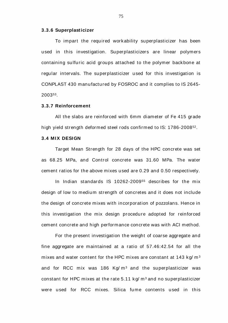
Fig: 3.4 Slump test before casting of slabs
Fig: 3.5 Slab specimen during casting
81
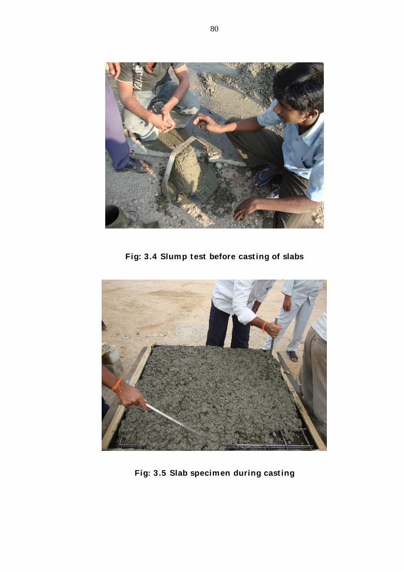
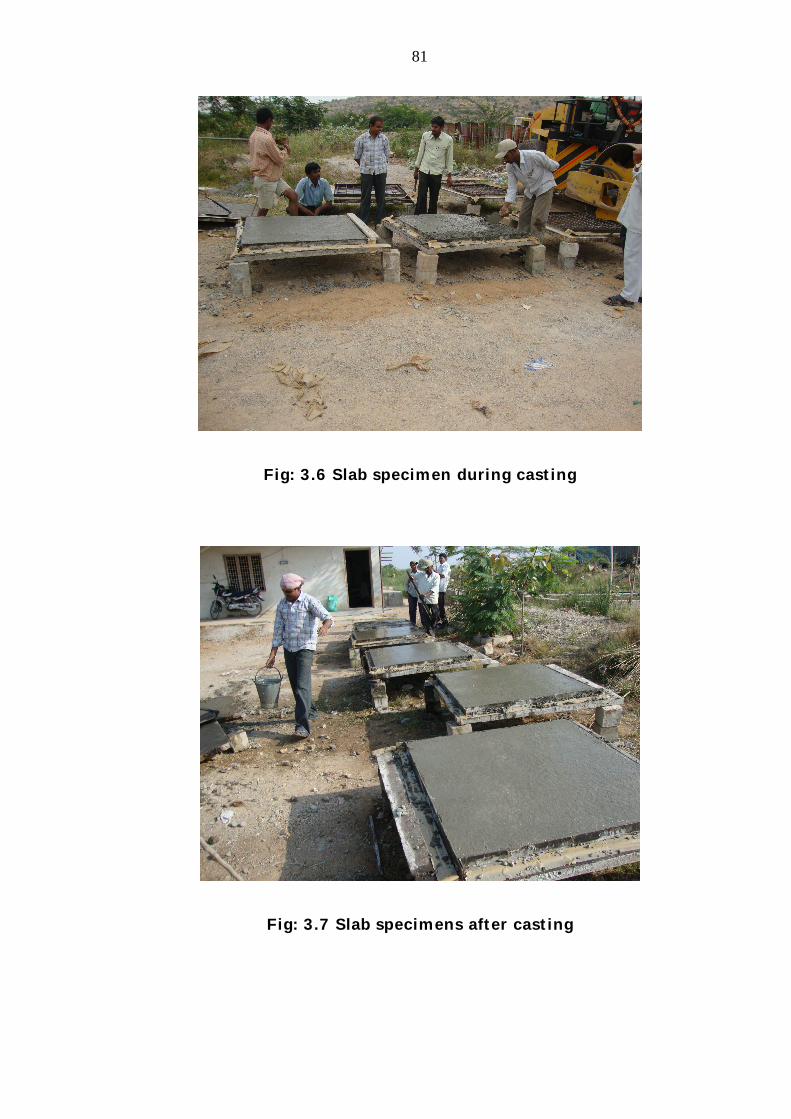
Fig: 3.6 Slab specimen during casting
Fig: 3.7 Slab specimens after casting

82
Fig: 3.8 Curing process
3.6 MECHANICAL PROPERTIES
Compression testing machine of capacity 2500 KN is used for
testing the concrete specimens. While testing the specimens,
precautions were taken to ensure load is axial. Tests are conducted on
the specimens for cube compression, cylinder compression and split
tensile strengths. The average three test results for each mix are
presented in Table 3.12. A Graph is drawn for cube compressive
strength Vs percentage replacement of cement by silica fume are
shown in Figure 3.9, similarly graph were drawn for cylindrical
compressive strength Vs percentage replacement of cement by silica
fume and split tensile strength Vs percentage replacement of cement
by silica fume and are shown in Figure 3.10 and 3.11 respectively.

83
Cubes of HPC and normal concrete (RCC M25) specimens are
tested in the laboratory. For HPC-0 to HPC-15 the cube compressive
strength increases from 59.55 to 71.11 MPa and from HPC-15 to HPC-
25 the cube compressive strength decreases from 71.11 to 63.11 MPa
and where as RCC-0 reported only 40.18 MPa. Maximum value of
cube compressive strength is obtained at 15% silica fume content and
the values are presented in Table 3.12.
In the present investigation cube compressive strengths are
increased up to 15% replacement of cement by silica fume, beyond
that compressive strengths are decreased. Similar observations are
made by Shanmugapriya and Uma (2013) 107 and Patil Shreekedar
and Kumbhar (2013)92 in their experimentation cube strengths are
increased up to 15% replacement of cement by silica fume beyond
15% the cube compressive strengths are decreased and Debabrata
Pradhan and Dutta (2013)33 the strengths are increased up to 20%
and 10% by subhro chakraorty and samaresh pan (2014)113.
Cylinders of HPC and normal concrete (RCC M25) specimens
are tested in the laboratory. The cylindrical compressive strength of
HPC cylinder specimens increased up to 15% replacement i.e., from
HPC-0 to HPC-15 the cylindrical compressive strength increased from
47.37 to 55.85 MPa and for HPC-15 to HPC-25 the cylindrical
compressive strength decreased from 55.85 to 48.78 MPa, where as
RCC-0 reported only 32.01 MPa. Maximum value of cylindrical
84
compressive strength is obtained where the silica fume replacement of
cement is at 15%, and these values are presented in Table 3.12.
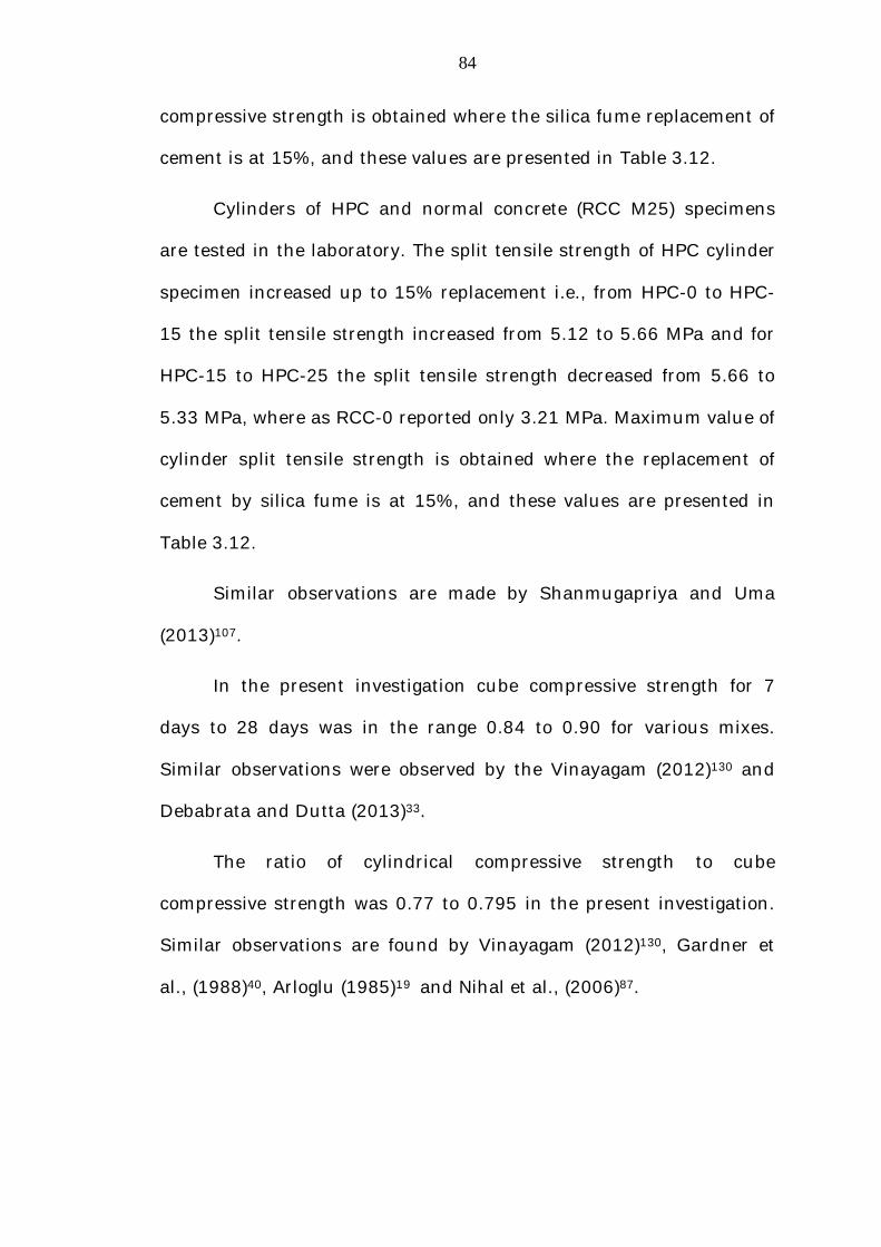
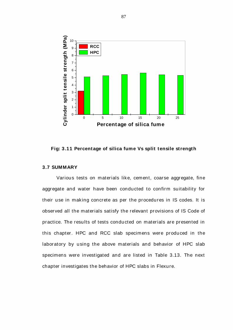
Cylinders of HPC and normal concrete (RCC M25) specimens
are tested in the laboratory. The split tensile strength of HPC cylinder
specimen increased up to 15% replacement i.e., from HPC-0 to HPC-
15 the split tensile strength increased from 5.12 to 5.66 MPa and for
HPC-15 to HPC-25 the split tensile strength decreased from 5.66 to
5.33 MPa, where as RCC-0 reported only 3.21 MPa. Maximum value of
cylinder split tensile strength is obtained where the replacement of
cement by silica fume is at 15%, and these values are presented in
Table 3.12.
Similar observations are made by Shanmugapriya and Uma
(2013)107.
In the present investigation cube compressive strength for 7
days to 28 days was in the range 0.84 to 0.90 for various mixes.
Similar observations were observed by the Vinayagam (2012)130 and
Debabrata and Dutta (2013)33.
The ratio of cylindrical compressive strength to cube
compressive strength was 0.77 to 0.795 in the present investigation.
Similar observations are found by Vinayagam (2012)130, Gardner et
al., (1988)40, Arloglu (1985)19 and Nihal et al., (2006)87.
85
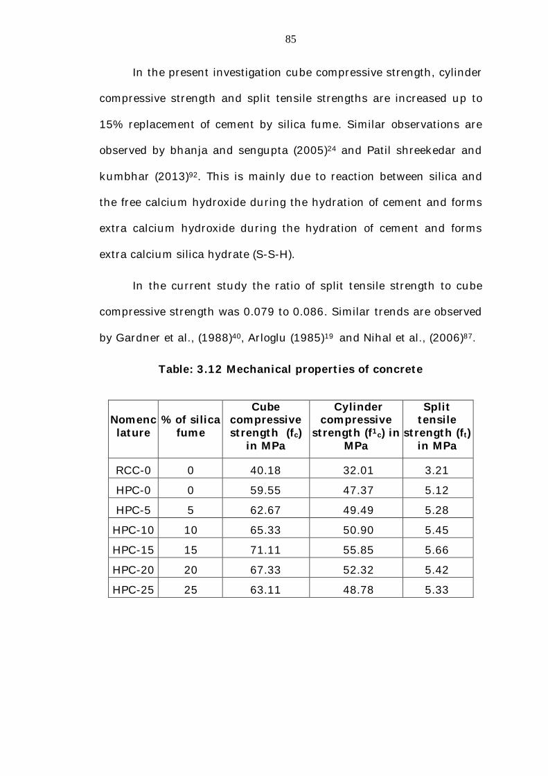
In the present investigation cube compressive strength, cylinder
compressive strength and split tensile strengths are increased up to
15% replacement of cement by silica fume. Similar observations are
observed by bhanja and sengupta (2005)24 and Patil shreekedar and
kumbhar (2013)92. This is mainly due to reaction between silica and
the free calcium hydroxide during the hydration of cement and forms
extra calcium hydroxide during the hydration of cement and forms
extra calcium silica hydrate (S-S-H).
In the current study the ratio of split tensile strength to cube
compressive strength was 0.079 to 0.086. Similar trends are observed
by Gardner et al., (1988)40, Arloglu (1985)19 and Nihal et al., (2006)87.
Table: 3.12 Mechanical properties of concrete
Nomenclature
% of silica fume
Cube compressive strength (fc)
in MPa
Cylinder compressive
strength (f1c) in MPa
Split tensile
strength (ft) in MPa
RCC-0 0 40.18 32.01 3.21
HPC-0 0 59.55 47.37 5.12
HPC-5 5 62.67 49.49 5.28
HPC-10 10 65.33 50.90 5.45
HPC-15 15 71.11 55.85 5.66
HPC-20 20 67.33 52.32 5.42
HPC-25 25 63.11 48.78 5.33

86
Fig: 3.9 Percentage of silica fume Vs Cube compressive strength
0 5 10 15 20 2505
10152025303540455055606570
Cyl
inde
r co
mpr
essi
ve s
tren
gth
(MPa
)
Percentage of silica fume
RCC HPC
Fig: 3.10 Percentage of silica fume Vs Cylindrical compressive
strength
0 5 10 15 20 2505
10152025303540455055606570758085
Cub
e co
mpr
essi
ve s
tren
gth
(MPa
)
Percentage of silica fume
RCC HPC
87
0 5 10 15 20 250
1
2
3
4
5
6
7
8
9
10
Cyl
inde
r sp
lit t
ensi
le s
tren
gth
(MPa
)
Percentage of silica fume
RCC HPC
Fig: 3.11 Percentage of silica fume Vs split tensile strength
3.7 SUMMARY
Various tests on materials like, cement, coarse aggregate, fine
aggregate and water have been conducted to confirm suitability for
their use in making concrete as per the procedures in IS codes. It is
observed all the materials satisfy the relevant provisions of IS Code of
practice. The results of tests conducted on materials are presented in
this chapter. HPC and RCC slab specimens were produced in the
laboratory by using the above materials and behavior of HPC slab
specimens were investigated and are listed in Table 3.13. The next
chapter investigates the behavior of HPC slabs in Flexure.

88
Table: 3.13 Nomenclature of slabs
Sl. No.
Slab Designation Explanation
1 RCCS-0 RCC slabs with all four edges simply supported and 0% replacement of cement by silica fume.
2 HPCS-0 HPC slab with all four edges simply supported and 0% replacement of cement by silica fume.
3 HPCS-5 HPC slab with all four edges simply supported and 5% replacement of cement by silica fume.
4 HPCS-10 HPC slab with all four edges simply supported and 10% replacement of cement by silica fume.
5 HPCS-15 HPC slab with all four edges simply supported and 15% replacement of cement by silica fume.
6 HPCS-20 HPC slab with all four edges simply supported and 20 % replacement of cement by silica fume.
7 HPCS-25 HPC slab with all four edges simply supported and 25% replacement of cement by silica fume.
8 RCCF-0 RCC slabs with all four edges fixed, containing 0% replacement of cement by silica fume.
9 HPCF-0 HPC slab with all four edges fixed and 0% replacement of cement by silica fume.
10 HPCF-5 HPC slab with all four edges fixed and 5% replacement of cement by silica fume.
11 HPCF-10 HPC slab with all four edges fixed and 10% replacement of cement by silica fume.
12 HPCF-15 HPC slab with all four edges fixed and 15% replacement of cement by silica fume.
13 HPCF-20 HPC slab with all four edges fixed and 20% replacement of cement by silica fume.
14 HPCF-25 HPC slab with all four edges fixed and 25% replacement of cement by silica fume.
89
The nomenclature used for the designation of different slab
specimens is chosen to understand easily and the details of
nomenclature used are explained below.
The first 3 letter in the nomenclature ‘HPC’ indicate High
Performance Concrete, ‘RCC’ indicate Reinforced Cement Concrete.
4th Letter indicate ‘S’ and ‘F’, simply supported and fixed
respectively.
The numerical in 5th position indicate the percentage weight of
cement replaced by silica fume.