test coupons and casting properties - steel · pdf file · 2017-10-10test coupons...
TRANSCRIPT

TEST COUPONS AND CASTING PROPERTIES
The mechanical test requirements for castings are given in the material specification in ASTM. Examples would be impact properties for grade LCC in A352, tensile strength requirements for grade 4N in A487, or ductility minimums for grade 70-40 in A27. The properties were developed for these alloy grades from keel block leg specimens. The mechanical test requirements are intended to venfy the quality of the steel and were not intended to establish the actual casting properties.
Most ASTM steel castings must conform to A781 or; if they are for pressure containing service, A703. Both of these specifications recognize that castings and test coupons exhibit different properties. In ASTM A781, this is indicated in Section 6--Tensile Requirements .
6.2 Unless otherwise specified by the purchaser, when mechanical properties are required by the product specifica- tion, test coupons may be cast integrally with the castings, or as separate blocks, in accordance with Figs. 1,2, or 3 except when Supplementary Requirement S 15 is specified. The test coupon in Fig. 3 shall be employed only for austenitic alloy castings with cross sections less than 2 1/2 in.8
8 Information on the relationship of mechanical properties determined on test coupons obtained as specified in 6.2 with thoseobtained from the casting may be found in "The Steel Casting Handbook," Fifth Edition, Steel Founders' society of America, pp. 15-35 through 15-43, 1980.
In 6.2, unless required by purchaser, all mechanical properties are developed using specimens from standard keel blocks. Reference is made in Note 8, to the SFSA Steel Casting Handbook.
If casting properties are required, S14 is to be mandated. Since heavy section castings do not develop the same properties as test coupons, the properties and location of
test specimens must be negotiated. S15 is for cast test coupons that have a thickness similar to the casting. Properties from this coupon are for the information of the purchaser unless the supplier agrees to meet the specification requirements in this heavy section coupon.
In 703, similar requirements hold, tensile test are given in Section 7.
7.4 Unless otherwise specified by the purchaser, test coupons may be cast integrally with the castings or as separate blocks in accordance with Fig. 1 and Table 2, with Fig. 2, or with Fig. 3, except when Supplementary Require- ment S26 is specified. The test coupon in Fig. 3 shall be employed only for austenitic alloy castings with cross sec- tions less than 2 1/2 in. [63.5 mm]. Tension test coupons shall be machined or ground to the form and dimension shown in Fig. 6 of Test Methods and Definitions A 370, except when investment castings are ordered. When investment castings are ordered, the manufacturer shall prepare test specimens in accordance with S3.2 of Specification A 732/A 732M.12
1 2 Information on the relationship of mechanical properties determined on test coupons obtained as specified in 7.1 and 7.4 with those obtained from the casting, may be found in "The Steel Castings Handbook," Fifth Edition, Steel Founders' Society of America, 1980, pp 15-35 through 15-43.
Unless S26 is specified, test coupons from keel blocks are used. This paragraph has a similar note that refers to the SFSA Steel Casting Handbook.
S14. Tension Test from Castings
S14.1 In addition to the tension test required by the matenal specification, test material shall be cut from the casting. The mechanical properties and location for the test material shall be agreed upon by the manufacturer and purchaser.
Test Coupon Versus Casting Properties Coupon properties refer to the properties of speci-
mens cut and machined from either a separately cast coupon, or a coupon which is attached to, and cast integrally with the casting. Typically, the legs of the ASTM standard keel block (A370) serve as the coupons. The legs of this keel block are 1.25 in. (32 mm) thick.
Casting properties refer to the properties of speci- mens cut and machined from the production casting itself. A casting from which properties are determined in this manner is either destroyed in the process, or requires repair welding to replace the metal removed for testing.
Test Coupons. The ASTM double-legged keel block, Fig. 15-67, is the most prominent design for test coupons among those in use and among those recognized by ASTM’s specification A370. Table 15-15 offers information on the reliability of tensile test results obtained from the double leg keel block. The data indicate that for two tests there is 95% assurance that the actual strength is within ±1,000 psi (6.9 MPa) of the actual ultimate tensile strength and within ±1,600 psi (11 MPa) of the actual yield strength. For tensile ductility the data show that two tests produce, with 95% assurance, the elongation results within ±3% and the reduction in area value within ±5%.
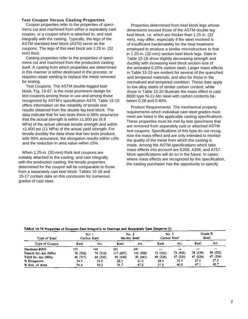
When 1.25-in. (32-mm) thick test coupons are suitably attached to the casting, and cast integrally with the production casting, the tensile properties determined for the coupon will be comparable to those from a separately cast keel block. Tables 15-16 and 15-17 contain data on this conclusion for numerous grades of cast steel.
Properties determined from keel block legs whose dimensions exceed those of the ASTM double leg keel block, i.e. which are thicker than 1.25 in. (32 mm), may differ, especially if the steel involved is of insufficient hardenability for the heat treatment employed to produce a similar microstructure to that in 1.25-in. (32-mm) section keel block legs. Data in Table 15-18 show slightly decreasing strength and ductility with increasing keel block section size of the annealed 0.26% carbon steel. Larger mass effects in Table 15-19 are evident for several of the quenched and tempered materials, and also for those in the normalized and tempered condition. These data apply to low alloy steels of similar carbon content, while those in Table 15-20 illustrate the mass effect in cast 8600 type Ni-Cr-Mo steel with carbon contents be- tween 0.28 and 0.40%.
Product Requirements. The mechanical property requirements which individual cast steel grades must meet are listed in the applicable casting specifications. These properties must be met by test specimens that are removed from separately cast or attached ASTM test coupons. Specifications of this type do not recog- nize the mass effect and are only intended to monitor the quality of the metal from which the casting is made. Among the ASTM specifications which take mass effects into account are E208, A356, and A757. More specifications will do so in the future. In cases where mass effects are recognized by the specification, the casting purchaser has the opportunity to specify
2

3

mechanical property testing of specimens which are machined from test coupons sized proportionally to the heaviest critical section of the casting. Typically, the test specimens are removed from the 1 /4 T location of the coupons, i.e. at mid-distance between the surface and center. The cost of such procedures is substantially larger than that involved in machining and testing specimens from the standard coupons shown in Figure 15-67. Customers therefore order tests from larger coupons only when the substantial extra cost is justified.
Casting Properties. The preceding discussions of the effects of section size on mechanical properties of carbon and low alloy steel and of discontinuities have clearly indicated that differences may exist between coupon properties and casting properties, i.e. the mechanical properties of specimens removed from the component may differ from properties of the component itself. With increasing frequency casting buyers are specifying that one or more castings be destroyed by cutting a coupon for testing from some section of the casting. These tests may serve to verify that expected quality levels are actually met because they reflect composition, heat treatment and especially
gating and risering procedures which control the soundness or freedom from shrinkage discontinuities. The trend toward determination of casting properties is limited, however, by cost considerations as well as the limited value of these tests. Composition and heat treatment can be verified at lower cost, more readily and more reliably by alternate conventional means, and discontinuities are in most instances as- sessed at lower cost by nondestructive testing. Moreover, the tensile properties determined from castings do not reliably reflect casting performance in terms of fatigue or sudden fracture. Full scale tests which duplicate service conditions offer the only reliable means of evaluating the performance of a component.
Thinner-walled castings, with sections of 3 in. (76 mm) or less tend to be less susceptible to the effect of section size. The mechanical properties are, of course, subject to the effect of discontinuities that may be present. One customer audit of tensile proper- ties at random casting locations in 0.25% carbon steel castings from nine foundries indicated the ultimate tensile strength, at a 1 /4 T distance from the surface, to be 75 ksi (517 MPa), or 10 ksi (69 MPa) over the
4

minimum specified for specimens removed from keel blocks. Only 2% of the tests were below the minimum value (Table 15-21). The percent elongation values averaged 25%, 5% above the minimum value for specimens from keel blocks. Of the tests, 21% were below the minimum (Table 15-21).
For heavier-wall castings, with sections in excess of 3 in. (76 mm), the effect of mass or section size is very important for quenched and tempered low alloy steels if the alloy content is insufficient to produce through-hardening. Figure 15-68 shows properties for separately cast coupons and those determined at different locations in actual castings. Lower strength values are evident for specimens removed from 5.5-in. thick sections of large Mn-Mo production castings. The composition of these steels is indicated in Table 15-22. The percentage decrease in tensile strength from surface to center of the 5.5-in. (140-mm), quenched and tempered Mn-Mo steels is of the order of 10%. The Charpy V-notch impact toughness at room tem- perature is significantly lower compared to the coupon. Tensile ductility, especially the reduction in area values, reveals the effects of section size and microporosity .
The steels with greater hardenability (Mn-Mo-V and Ni-Cr-Mo of Table 15-22) exhibit no appreciable de- crease in strength as a function of specimen distance from the casting surface (Figure 15-69). Toughness for these steels does in fact increase with distance
5
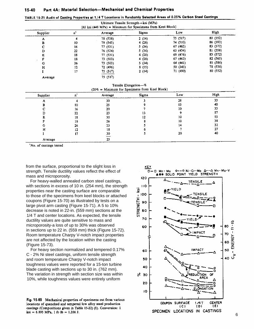
from the surface, proportional to the slight loss in strength. Tensile ductility values reflect the effect of mass and microporosity.
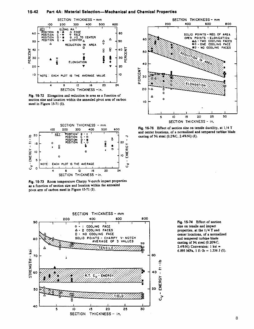
For heavy-walled annealed carbon steel castings, with sections in excess of 10 in. (254 mm), the strength properties near the casting surface are comparable to those of the specimens from keel blocks or attached coupons (Figure 15-70) as illustrated by tests on a large pivot arm casting (Figure 15-71). A 5 to 10% decrease is noted in 22-in. (559 mm) sections at the 1/4 T and center locations. As expected, the tensile ductility values are quite sensitive to mass and microporosity-a loss of up to 30% was observed in sections up to 22 in. (559 mm) thick (Figure 15-72). Room temperature Charpy V-notch impact properties are not affected by the location within the casting (Figure 15-73).
For heavy section normalized and tempered 0.17% C - 2% Ni steel castings, uniform tensile strength and room temperature Charpy V-notch impact toughness values were reported for a 15-ton turbine blade casting with sections up to 30 in. (762 mm). The variation in strength with section size was within 10%, while toughness values were entirely uniform
6

7
8
because this grade of steel develops uniform micro- structure and because toughness is not as sensitive to microporosity as tensile ductility (Figures 15-74 and
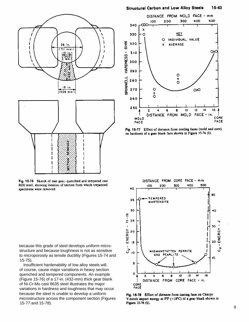
Insufficient hardenability of low alloy steels will, of course, cause major variations in heavy section quenched and tempered components. An example (Figure 15-76) of a 17-in. (432-mm) thick gear blank of Ni-Cr-Mo cast 8635 steel illustrates the major variations in hardness and toughness that may occur because the steel is unable to develop a uniform microstructure across the component section (Figures
15-75).
15-77 and 15-78). 9
THIS PROBLEM HAS BEEN COMMENTED ON AT SOME L E N G T H IN T H E PROCEEDINGS - 1st INTERNATIONAL STEEL F O U N D R Y CONGRESS.
Understanding Various National and International Specifications Raymond W. Monroe Research Director Steel Founders ' Society of Amer ica Des Pla ines, I l l ino is
Whenever possib le, i t becomes the responsib i l i ty of spec- i f icat ion wr i t ing bodies to t ry and resolve the conf l ic t by reasonable requiements that are meaningfu l to the customer but s t i l l economical l y at- ta inable by the foundry. The mechanical proper t ies of a s teel cast ing depend pr imar i ly on the in teract ion of cast ing design, sect ion s ize, chemist ry and heat t reatment . Mechanical proper t ies requi rements in mater ia ls speci f icat ions are arr ived at by s tat is t ica l analys is of test resul ts f rom standard test bars. I t is commonly recognized that the mechanical proper t ies can decrease as the cast ing sect ion s ize increases, especia l ly toughness and duct i l i ty in carbon and low a l loy s teels . I n BSI standards, there is a note that : "The mechanical proper t ies requi red shal l be obta ined f rom test bars cast e i ther seperate ly f rom or at tached to the cast ings which they refer . The test va lues so exhib i t represent , there- fore, the qual i ty of the steel f rom which the cast ing have been poured; they do not repersent the proper t ies of the cast ings themselves, which may be af fected by sol id i f icat ion condi t ions and rate of cool ing dur ing heat t reat- ment , which in turn are in f luenced by cast ing th ickness, s ize and shape".
One source of conf l ic t wi th customers in the d i f ference in proper t ies between the test bar and cast ings. Some publ ished guidel ines are avai lab le but there needs to be more concrete speci f icat ion work on the proper t ies and cast ing th ickness re lat ionship. Ei ther a table of req- u i rements showing mechanical proper t ies min imums at var ious sect ion s izes or a th ickness l imi tat ion on the a l ready establ ished min imums for var ious grades of cast s teel mater ia ls should be establ ished. The uni form sect ion th ickness and shape of wrought s teel forms a l lows a t ight speci f icat ion at the actual mechanical proper t ies in each product form. Steel cast ings manufacturers should respond wi th speci f icat ion guidel ines to the design engineer so that cast ings do not suf fer in the market p lace.
10

PROCEEDINGS - 38th SFSA T & O CONFERENCE 1983
Specifications; Cause, Effect and Some Examples Victor G. Behal Engineer ing Mater ia l & Cast ing Specia l is t Dofasco, Inc. , Hami l ton, Ontar io , Canada
Capaci ty : 3,500 t /mo No. Employed: 700 Steels: Carbon, low al loy, h igh a l loy Products: AII
ABSTRACT
Def in i t ion, or ig in, purpose and sources; Component par ts and impl icat ions; and Deta i led requi rements are normal ly found in speci f icat ions for s teel cast ings. One area that i s poor ly understood by some users is the in ter- pretat ion of mechanical proper t ies ' va lues and mass ef fect . T ightening of speci f icat ions can be a resul t o f problems encountered by customers, for example, the Al -N test method proposed as a new addi t ion to ASTM A703. Also discussed is Qual i ty Assurance - reason and documentat ion. There is a hugh cost of Nor th Amer ican adversary system that is prevalent in our industry - pi t t ing product ion versus qual i ty contro l . Fol lowing speci f icat ions to the le t ter is inappropr iate - beware of loopholes and consequences.
As shown in Figure 1, speci f icat ions are wr i t ten statements of the requi rements, both technical and commer ica l , for par t icu lar products or serv ices.
They come about f rom the need to prov ide a uni form basis of in format ion to vendors, inc luding acceptance cr i ter ia .
New speci f icat ions and rev is ions of those ex is t ing are the resul t o f exper i - ence in serv ice, new serv ice demands or technological developments.
Most speci f icat ions are produced by nat ional speci f icat ion wr i t ing bodies, such as ASTM, DIN, AFNOR BSI and others, regulatory agencies such as ASME or in ternat ional agencies such as ISO. There are a lso speci f icat ions produced by mi l i tary agencies and even pr ivate companies, though in most cases th is is a dupl icat ion of ef for ts which tend to compl icate fur ther an a l ready complex s i tuat ion.
Whi le speci f icat ions are wr i t ten in di f ferent ways, there are at least three main const i tuents:
1. SCOPE:
The scope descr ibes what the speci f ica- t ion is appl icable to.
2. MANDATORY REQUIREMENTS:
Mandatory requi rements are conta ined in the body of the speci f icat ion and usual ly consis t o f a number of para- graphs, each addressing a speci f ic requi rement such as chemical composi - t ion, heat t reatment , mechanical proper- t ies, repai r , e tc .
3. SUPPLEMENTARY REQUIREMENTS:
Supplementary requi rements are appl ic- able only i f cal led up in the inqui ry and order . These cover specia l requi re- ments which may be cal led fo r in the case of some speci f ic appl icat ions, usual ly depending upon the sever i ty of serv ice or when product fa i lure would have ser ious consequences.
11

In the case of s teel cast ings, the f i rs t speci f icat ion essent ia l is the chemical composi t ion, which is se lected on the basis of serv ice requi rements, i .e . s t rength, duct i l i ty and envi ronmenta l factors such as temperatures, corros ion, etc .
Speci f icat ions do not guarantee that a l l chemical composi t ions with in the speci - f ied l imi ts shal l meet the requi rements for mechanical proper t ies, regard less of heat t reatment . I t is necessary to se lect the proper l imi ts wi th in the speci f icat ion ranges, to assure the at ta inment of the mechanical proper t ies speci f ied.
For some appl icat ions, the heat t reat- ment may be speci f ied, to assure a desi red qual i ty which is not necessar i ly expressed by the requi rements for mechanical proper t ies. For other appl icat ions, the choice of heat t reat- ment is le f t to the opt ion of the manufacturer . For instance, fer r i t ic s teels in tended for h igh temperature serv ice are not permi t ted to be l iqu id quenched, to prevent degradat ion of creep st rength; for low temperature
serv ice, fer r i t ic s teel cast ings are water quenched to enhance low tempera- ture duct i l i ty .
Mechanical proper t ies are a lso speci f ied addi t ional ly , and many speci f icat ions reference other speci f icat ions, common to s tandards of the same type. Usual ly the la t ter deal s t r ic t ly with the methods of test ing, to determine chemi- ca l composi t ion, mechanical proper t ies and other cr i ter ia such as soundness, f in ish, etc .
Supplementary requi rements are stated, as appl icable. Let us consider for a moment , the rami f icat ions of the d i f fer - ence in chemical composi t ion.
F igures 2 and 3 were chosen t o i l lu - strate the drast ic in f luence of a change in chemical composi t ion by the addi t ion of just a s ingle e lement , on the me- chanical proper t ies of the steel .
F igure 2 shows that the chemical com- posi t ion of Dofasco grade 1331 and 1431 is pract ica l ly ident ica l , except that the la t ter grade conta ins .40% molyb- denum. The d i f ference in chemist ry resul ted in an increase in the Ideal Cr i t ica l Diameter quench hardenabi l i ty (D. I . ) value f rom 2.20 to 4.27" and in the carbon equivalent f rom .61 to .68%.
12
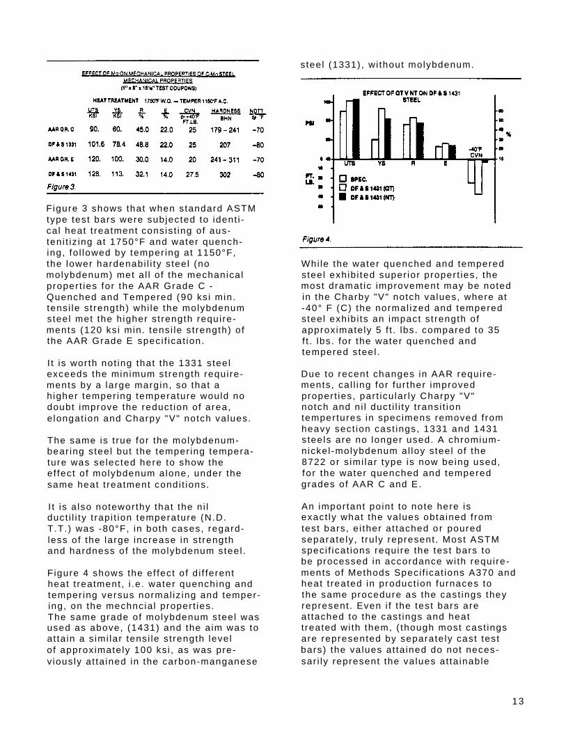
steel (1331) , wi thout molybdenum.
Figure 3 shows that when standard ASTM type test bars were subjected to ident i - ca l heat t reatment consis t ing of aus- teni t iz ing at 1750°F and water quench- ing, fo l lowed by temper ing at 1150°F, the lower hardenabi l i ty s teel (no molybdenum) met a l l o f the mechanical proper t ies for the AAR Grade C - Quenched and Tempered (90 ksi min. tensi le s t rength) whi le the molybdenum steel met the h igher s t rength requi re- ments (120 ksi min. tens i le s t rength) of the AAR Grade E speci f icat ion.
I t is wor th not ing that the 1331 steel exceeds the minimum strength requi re- ments by a large margin, so that a h igher temper ing temperature would no doubt improve the reduct ion of area, e longat ion and Charpy "V" notch values.
The same is t rue for the molybdenum- bear ing steel but the temper ing tempera- ture was selected here to show the ef fect of molybdenum alone, under the same heat t reatment condi t ions.
I t is a lso noteworthy that the ni l duct i l i ty t rapi t ion temperature (N.D. T.T.) was -80°F, in both cases, regard- less of the large increase in strength and hardness of the molybdenum steel .
F igure 4 shows the ef fect of d i f ferent heat t reatment , i .e . water quenching and temper ing versus normal iz ing and temper- ing, on the mechncia l proper t ies. The same grade of molybdenum steel was used as above, (1431) and the a im was to at ta in a s imi lar tensi le s t rength level of approximate ly 100 ksi , as was pre- v iously at ta ined in the carbon-manganese
Whi le the water quenched and tempered steel exhib i ted super ior proper t ies, the most dramat ic improvement may be noted in the Charby "V" notch values, where at -40° F (C) the normal ized and tempered steel exhib i ts an impact s t rength of approximate ly 5 f t . lbs. compared to 35 f t . lbs. for the water quenched and tempered steel .
Due to recent changes in AAR requi re- ments, ca l l ing for fur ther improved proper t ies, par t icu lar ly Charpy "V" notch and ni l duct i l i ty t ransi t ion tempertures in specimens removed f rom heavy sect ion cast ings, 1331 and 1431 steels are no longer used. A chromium- n ickel -molybdenum al loy s teel o f the 8722 or simi lar type is now being used, fo r the water quenched and tempered grades of AAR C and E.
An important point to note here is exact ly what the values obta ined f rom test bars, e i ther at tached or poured separate ly , t ru ly represent . Most ASTM speci f icat ions requi re the test bars to be processed in accordance with requi re- ments of Methods Speci f icat ions A370 and heat t reated in product ion furnaces to the same procedure as the cast ings they represent . Even i f the test bars are at tached to the cast ings and heat t reated with them, ( though most cast ings are represented by separate ly cast test bars) the values at ta ined do not neces- sar i ly represent the values at ta inable
13
i f the test specimens were to be removed f rom the cast ings the test bars repre- sent .
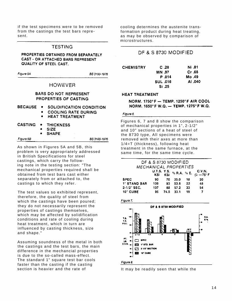
As shown in Figures 5A and 5B, th is problem is very appropr iate ly addressed in Bri t ish Speci f icat ions for s teel cast ings, which carry the fo l low- ing note in the test ing sect ion: "The mechanical proper t ies requi red shal l be obta ined f rom test bars cast e i ther separate ly f rom or at tached to, the cast ings to which they refer .
The test va lues so exhib i ted represent , therefore, the qual i ty of s teel f rom which the cast ings have been poured; they do not necessar i ly represent the proper t ies of cast ings themselves, which may be af fected by sol id i f icat ion condi t ions and rate of cool ing dur ing heat t reatment , which in turn are in f luenced by cast ing th ickness, s ize and shape."
Assuming soundness of the meta l in both the cast ings and the test bars, the main d i f ference in the mechancia l proper t ies is due to the so-cal led mass-ef fect . The standard 1" square test bar cools faster than the cast ing i f the cast ing sect ion is heavier and the rate of
cool ing determines the austeni te t rans- format ion product dur ing heat t reat ing, as may be observed by compar ison of microst ructures.
F igures 6, 7 and 8 show the compar ison of mechanical proper t ies in 1", 2-1/2" and 10" sect ions of a heat of s teel o f the 8730 type, Al l specimens were removed with the i r axes at more than 1/4=T ( th ickness) , fo l lowing heat t reatment in the same furnace, at the same t ime, for the same t ime cyc le.
I t may be readi ly seen that whi le the
14
tens i le proper t ies are met in al l three sect ions, except for a s l ight drop below the min imum in the reduct ion of area of the 10" sect ion, there is a drast ic drop-of f in the Charpy "V" notch value at -75° F f rom 48 f t . lb f . in the 1" sect ion to 7 f t . lb f . in the 10" sec- t ion, whi le the 2-1/2" sect ion exhib i ts an even bet ter va lue than the 1" sec- t ion, due no doubt to the lower hardness and correspondingly lower s t rength of the specimen.
Higher temper ing temperatures for the 1" test bar , to lower the hardness and st rength to that comparable wi th the 2-1/2" sect ion resul ts , would no doubt increase the Charpy values of the 1" bar specimen to exceed those of the 2-1/2" bar.
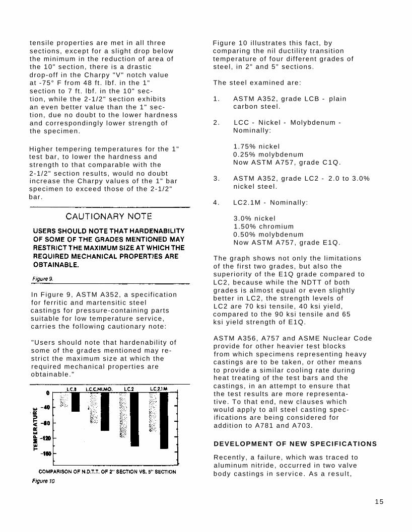
In Figure 9, ASTM A352, a speci f icat ion for fer r i t ic and martensi t ic s teel cast ings for pressure-conta in ing par ts su i table for low temperature serv ice, carr ies the fo l lowing caut ionary note:
"Users should note that hardenabi l i ty of some of the grades ment ioned may re- s t r ic t the maximum size at which the requi red mechanical proper t ies are obta inable."
F igure 10 i l lust rates th is fact , by compar ing the ni l duct i l i ty t ransi t ion temperature of four d i f ferent grades of s teel , in 2" and 5" sect ions.
The steel examined are:
1. ASTM A352, grade LCB - pla in carbon steel .
2. LCC - Nickel - Molybdenum - Nominal ly :
1.75% nickel 0.25% molybdenum Now ASTM A757, grade C1Q.
3. ASTM A352, grade LC2 - 2.0 to 3.0%nickel s teel .
4. LC2.1M - Nominal ly :
3.0% nickel 1.50% chromium 0.50% molybdenum Now ASTM A757, grade E1Q.
The graph shows not only the l imi tat ions of the f i rs t two grades, but a lso the super ior i ty of the E1Q grade compared to LC2, because whi le the NDTT of both grades is a lmost equal or even s l ight ly bet ter in LC2, the st rength levels of LC2 are 70 ksi tensi le , 40 ks i y ie ld, compared to the 90 ksi tensi le and 65 ksi y ie ld s t rength of E1Q.
ASTM A356, A757 and ASME Nuclear Code prov ide for other heavier test b locks f rom which specimens represent ing heavy cast ings are to be taken, or other means to prov ide a s imi lar cool ing rate dur ing heat t reat ing of the test bars and the cast ings, in an at tempt to ensure that the test resul ts are more representa- t ive. To that end, new c lauses which would apply to a l l s teel cast ing spec- i f icat ions are being considered for addi t ion to A781 and A703.
DEVELOPMENT OF NEW SPECIFICATIONS
Recent ly , a fa i lure, which was t raced to a luminum ni t r ide, occurred in two valve body cast ings i n serv i ce . As a r esu l t ,
15
the user proposed a new requi rement considered for p lacement in to ASTM standards, in an at tempt to prec lude reoccurrence of such fa i lures.
The proposal involves the inc lus ion in the supplementary requi rements, the requi rement of an ac id etch test to prove the presence of absence of a luminum ni t r ide, when the steel con- ta ins a luminum over a cer ta in minimum. This instance serves to ind icate how addi t ional requi rements come about .
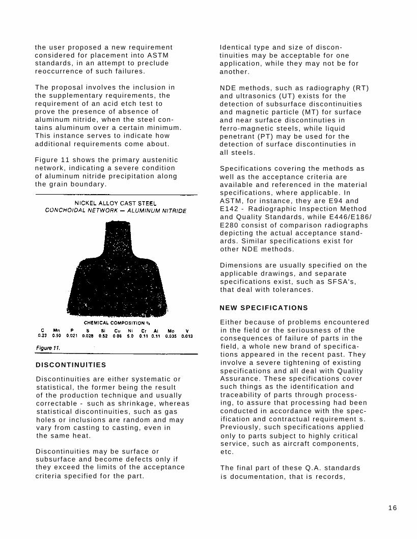
F igure 11 shows the pr imary austeni t ic network, ind icat ing a severe condi t ion of a luminum ni t r ide prec ip i ta t ion a long the gra in boundary.
DISCONTINUlTlES
Discont inui t ies are e i ther systemat ic or stat is t ica l , the former being the resul t of the product ion technique and usual ly correctable - such as shr inkage, whereas stat is t ica l d iscont inui t ies, such as gas holes or inc lus ions are random and may vary f rom cast ing to cast ing, even in the same heat .
Discont inui t ies may be sur face or subsur face and become defects only i f they exceed the l imi ts of the acceptance cr i ter ia speci f ied f o r the par t .
Ident ica l type and s ize of d iscon- t inu i t ies may be acceptable for one appl icat ion, whi le they may not be fo r another .
NDE methods, such as radiography (RT) and u l t rasonics (UT) exis ts for the detect ion of subsur face d iscont inui t ies and magnet ic par t ic le (MT) for sur face and near sur face d iscont inut ies in fer ro-magnet ic s teels , whi le l iqu id penetrant (PT) may be used for the detect ion of sur face d iscont inut ies in al l s teels .
Speci f icat ions cover ing the methods as wel l as the acceptance cr i ter ia are avai lab le and referenced in the mater ia l speci f icat ions, where appl icable. In ASTM, for instance, they are E94 and E142 - Radiographic Inspect ion Method and Qual i ty Standards, whi le E446/E186/ E280 consis t o f compar ison radiographs depict ing the actual acceptance stand- ards. Simi lar speci f icat ions ex is t for other NDE methods.
Dimensions are usual ly speci f ied on the appl icable drawings, and separate speci f icat ions ex is t , such as SFSA's, that deal wi th to lerances.
NEW SPECIFICATIONS
Either because of problems encountered in the f ie ld or the ser iousness of the consequences of fa i lure of par ts in the f ie ld , a whole new brand of speci f ica- t ions appeared in the recent past . They involve a severe t ightening of ex is t ing speci f icat ions and a l l deal with Qual i ty Assurance. These speci f icat ions cover such th ings as the ident i f icat ion and t raceabi l i ty of par ts through process- ing, to assure that processing had been conducted in accordance with the spec- i f icat ion and contractual requirement s . Previously , such speci f icat ions appl ied only to par ts subject to h ighly cr i t ica l serv ice, such as a i rcraf t components, etc .
The f ina l par t o f these Q.A. standards i s documentat ion, that i s records,
16

ranging f rom test repor ts cross-refer- encing cast ings to heat numbers by ind iv idual ser ia l numbers, to weld ing procedures, welders ' qual i f icat ion records, weld repai r maps, heat t reat furnace char ts and NDE personnel qual i - f icat ions and resul ts of examinat ion of cast ings.
Many of the requi rements current ly encountered in th is regard, have been brought upon industry by i tse l f due to inadequate qual i ty contro l in the past .
Some of these qual i ty- re lated problems may be t raced to the adversary system so prevalent in North Amer ica, where Product ion personnel consider a l l "Qual i ty" or iented personnel , i .e . Meta l lurg ica l , Qual i ty Contro l and Inspect ion, as an unnecessary ev i l , on ly h inder ing product ion.
" I f a speci f icat ion st ipu lates only per iodic test ing, to assure maintenance of a cer ta in qual i ty level on a s tat is- t ica l basis , why stop product ion and invest igate the cause of an occasional fa i lure, instead of passing the fa i led lo t and test ing another one? Af ter a l l , the spec, does not ca l l for test ing of each heat and who knows what we pass when we do not need to test each heat?"
Some t ime ago, a manufacturer sh ipped cast ings conta in ing 4.0% manganese for a speci f icat ion a l lowing .85% manganese maximum, and whi le the test bar , poured ear ly in the heat , met requi rements, cast ings poured f rom the ta i l end of the heat conta in ing the h igh manganese due to a method of lad le a l loy ing which caused Mn and C enr ichment dur ing the last par t o f the pour , were as hard as 400 Br inel l and fa i led, Ever s ince, a l l manufacturers of th is huge tonnage steel cast ing product must take the sample for chemical analys is f rom the f i rs t 25% of the heat poured and another sample, for manganese determinat ion and repor t , f rom the last usable cast ing of each heat f rom which such cast ings are poured.
I t is prec ise ly th is k ind of reasoning
and error that gets industry in to t rouble, loses business to compet i t ion and eventual ly resul ts in the fur ther t ightening of speci f icat ions, which wi l l then cal l for 100% inspect ion, thus ra is ing costs.
I t is necessary to l ive up to not only the le t ter of speci f icat ions, but more important ly , to the spi r i t or in tent and th is wi l l be achieved in the future only through the fu l lest cooperat ion of a l l personnel and the real izat ion that a l l depar tments of any company work toward the common goal and that i s to sat is fy the customers demands.
Stretching speci f icat ions does not pay, as is wel l i l lust rated in Figures 12, 13 and 14.
1 7

REFERENCES
1. ASM Meta l Handbook, N in th Ed i t ion , Vo lume 1 - Proper t ies and Se lec- t ion : I rons and Stee ls .
2 . Br i t i sh Standards Ins t i tu t ion - Spec i f i ca t ion BS3100:1976 - Stee l Cast ings fo r Genera l Eng ineer ing Pur poses.
3. 1983 Annua l Book of ASTM Standards , Sect ion 1 , Vo lume 0.1-02 - Ferrous Cast ings ; Fer roa l loys : Sh ip Bu i ld - ing - ASTM A352-82 - Ferr i t i c and Mar tens i t i c S tee l Cast ings fo r Pressure-Conta in ing Par ts Su i tab le for Low Temperature Serv ice ,
4 . Ju l ian Tou louse, Owens - I l l ino is Glass Company.
18

STEEL F O U N D R Y FACTS 354 February 1983
Mechanical Properties of Heavy Section Castings: An Overview Raymond Monroe Steel Founders ’ Society of Amer ica, Des Pla ines, I l l ino is
INTRODUCTION
The ef fect of sect ion s ize on proper t ies in cast ings can be separated in to e i ther a geometr ica l or metal lurg ica l s ize ef fect . The geometr ica l s ize ef fect is apparent when test ing d i f ferent s ize specimens wi th the same metal - lurg ica l or ig in. On the other hand, the meta l lurg ica l s ize ef fect is the test ing of s imi lar ly s ized specimens machined f rom cast ings of d i f ferent s izes.(1,2) In heavy sect ion cast ing, both sect ion s ize ef fects are ev ident . An under- s tanding of both types of s ize ef fects wi l l help the producer min imize the adverse impact of sect ion s ize on the serv ice l i fe of the cast ing.
The proper t ies of in terest to the modern designer inc lude tensi le , impact , f racture toughness, and fat igue. Yie ld s t rength was the c lass ica l engineer ing proper ty used as a basis for design. However, most components that fa i l , fa i l s tar t ing f rom a f law and exhib i t an absence of p last ic deformat ion or yie ld- ing. The fa i lure may have occurred star t ing at the f law wi th a s ingle load appl icat ion ( f racture toughness) or the f law may have prov ided a s i te for a crack which grew to cr i t ica l s ize only af ter mul t ip le appl icat ions of the load ( fat igue and f racture toughness) . (3) Fracture toughness and fat igue tests are successfu l in al lowing design calcu- la t ions to avoid these fa i lures.
METALLURGICAL SIZE EFFECT
The metal lurg ica l s ize ef fect is at t r ib- uted to the changes of microst ructure inherent in producing and heat t reat ing d i f ferent s ize cast ings. Inc luded in th is category are normal ef fects , l ike changes in grain s ize, and lack of through-hardening; and defects more prone to occur in large cast sect ions such as
large inc lus ion s ize, temper embr i t t le- ment , rock candy, microshr inkage, sur face roughness, and sur face p ick-up. Al l of these ef fects normal ly increase as the sect ion s ize of the cast ing in - creases.
Grain Size and Heat Treat ing Ef fects . The gra in s ize of s teel increases with an increase in cast ing sect ion s ize as g iven in Table 1. (4 ,5 ,6 ) In general , the mechanical proper t ies of a s teel are re lated to the gra in s ize. (7) F igure 1 shows the benef i ts of gra in ref inement on the tensi le proper t ies of mi ld s teel . (7, 8,9) As the gra in s ize becomes smal ler - the tensi le s t rength increases. Simi lar ly , F igure 2, shows how the gra in s ize af fects the f racture st rength, a f racture mechanic ’s measure of the res is tance to crack propogat ion. (7)
The fat igue behavior of s teel is a lso af fected by the gra in s ize. (8) The fat igue l imi ts of two steels with di f fer - ent gra in s izes are compared in Figure 3. (8) There was an increase of en- durance l imi t with a decrease in grain s ize. Larger gra in s ize associated with larger cast ing sect ions lead to some decrease in tens i le s t rength, f racture toughness and fat igue behavior .
19

The microst ructure of a s teel cast ing can normal ly be ref ined by heat t reatment . Heat t reatment can produce f iner micro- s t ructures than the as cast micro- s t ructure. However, th is f iner micro- s t ructure depends on the cool ing rate f rom t he aus ten i t i z i ng t empera tu re . I n th icker sect ions i t is impossib le to
cool the center of a cast ing as quick ly as the edge. The f iner microst ructure nearer the sur face g ives bet ter me- chanical proper t ies as shown in Figure 4 and 5. (1 ,6 ,9 ,10 ,11 ,12 ,13 ,14 ,15) In Figure 4, sect ions of about 5 to 10 inches were tested for tensi le and impact p rope r t i es . (14 ) The var ia t ion f r om sur face to center is shown and; as
20

expected, the tensi le s t rength is less in the center and the t ransi t ion temperature is h igher . The fat igue endurance l imi ts of some var ious steels in 1-1/4" , 3" and 6" sect ions are shown in Figure 5. (16) In the 1030 specimens, normal ized and tempered, the proper t ies are fa i r ly insensi t ive to sect ion s ize up to 6 inches, wi th the endurance l imi t being about 37,000 ps i . With the 8630 mater ia l , normal ized and tempered, the endurance l imi t improved with a value of 44,000 ps i in the center of the 1-1/4" th ickness. The 8635 mater ia l , quenched and tempered, had endurance l imi ts of 54,000 ps i , 48,000 ps i , and 38,000 ps i in the center of the 1-1/4" , 3" , and 6" th ickness. The sect ion s ize var ia t ions are the most pronounced in the quenched and tempered condi t ion; s ince quenching cannot a lways ext ract the heat in the center of a th ick sect ion fast enough to form martensi te .
The s ingle most important and least
avoidable ef fect of sect ion s ize is the coarseness of the microst ructure, s ince the cool ing rate at the center of th ick sect ions wi l l never be rapid. (1) In tercr i t ica l heat t reatment might a l low some ref inement of the micro- s t ructure in th ick sect ions. (17,18)
Casting Discontinuit ies and Defects Cast ing larger sect ion s izes can agravate a number of cast ing d iscont inui t ies l ike the larger inc lus ion s izes repor ted in Table I I . (4,6) The larger inc lus ion s izes do not have much of an ef fect on tensi le s t rength but do lower the impact s t rength, F igure 6, throughout the range. Larger inc lus ions a lso lower the fat igue res is tance, F igure 7, par t icu-
21

lar ly in higher s t rength steels . (8,10, 11,19,20)
One source of embr i t t lement agravated by larger sect ion s izes is a luminum ni t r ide, or " rock candy" f ractures. F igure 8 i l lust rates the decreasing to lerance for a luminum and n i t rogen wi th a decreasing cool ing rate. This concern and inc lus ion type contro l shows the need for a wel l thought out and tested deoxid izat ion pract ice for heavy sect ion cast ings. (4,21 )
Another problem agravated by th ick
sect ions is temper embr i t t lement . Temper embr i t t lement is caused by the segregat ion of impur i t ies such as phos- phorus, arsenic , ant imony, and t in in to the gra in boundary areas. The embr i t t le- ment shows as an upward shi f t of the t ransi t ion temperature af ter exposure to temperatures in the range of 750- 1100° F. Temper embr i t t lement can occur in large sect ions dur ing cool ing f rom the temper ing.(5,7,22) Cool ing f rom weld ing can a lso induce temper embr i t t lement . (22)
Other defects are more prone to happen in th ick sect ions such as microshr inkage, sur face roughness, and sur face contami- nat ion. These defects can a lso cause some deleter ious ef fects on the pro- per t ies of s teel cast ings.(1,4,5,10, 11,23)
GEOMETRICAL SIZE EFFECT
The geometr ica l s ize ef fect is measured as the d i f ference in proper t ies obta ined when d i f ferent s ized specimens of s imi lar meta l lurg ica l background are tested. This s ize ef fect has been invest igated for tensi le , impact and fat igue pro- per t ies. In general , the mechanical proper t ies of a s teel are not as favor- able in the larger s ize specimens. This decrease in proper t ies with larger specimens had been expla ined by greater probabi l i ty of favorable gra in or ienta- t ion on the sur face or larger f laws when a greater amount of mater ia l is tested. (16) Whi le th is s tat is t ica l explana- t ion does of fer some rat ionale for the poorer proper t ies found in larger speci - mens, f racture mechanics of fers a more sat is fy ing explanat ion. (22)
- Linear Elast ic Frac tu re Mechan ics Fracture Mechanics (LEFM) was developed to expla in the fa i lures of br i t t le mater ia ls in the presence of defects at s t resses wel l be low the st rength of the mater ia l . LEFM was subsequent ly extended to expla in the behavior of s teels especia l ly h igh st rength steels in the presence of a f law. (3,5,7,10,24,25, 26,27) The beauty of LEFM is the use of one var iable that re lates load, f law s ize, and par t conf igurat ion to fa i lure. This al lows the use of LEFM test resul ts
22
to be used in design to prevent br i t t le type fa i lures. The most widely used var iable use to character ize LEFM be- havior of mater ia ls is K I C . Other var iables have been used such as G and J I C . J I C has some advantages over K I C in lower s t rength steels s ince i t was developed for mater ia l exhib i t ing larger amounts of y ie ld ing in fa i lure; however, K I C is the most common measure- ment . (26,27)
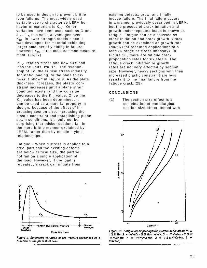
re lates st ress and f law s ize and K I Chas the uni ts , ks i / i n . The re lat ion- sh ip of Kc, the cr i t ica l s t ress in tensi ty for s tat ic loading, to the p late th ick- ness is shown in F igure 9. As the p late th ickness increases, the p last ic con- s t ra int increases unt i l a p lane st ra in condi t ion ex is ts ; and the Kc value decreases to the K I C value. Once the K I C value has been determined, i t can be used as a mater ia l proper ty in design. Because of the ef fect of in - creasing sect ion s ize, increasing the p last ic constra int and establ ish ing p lane st ra in condi t ions, i t should not be surpr is ing that th icker sect ions fa i l in the more br i t t le manner expla ined by LEFM, rather than by tensi le - yie ld re lat ionships.
Fat igue - When a st ress is appl ied to a s teel par t and the ex is t ing defects are below cr i t ica l s ize, the par t wi l l not fa i l on a s ingle appl icat ion of the load. However, i f the load is repeated, a crack can in i t ia te f rom
exis t ing defects, grow, and f ina l ly induce fa i lure. The f ina l fa i lure occurs in a manner prev iously descr ibed in LEFM, but the process of crack in i t ia t ion and growth under repeated loads is known as fat igue. Fat igue can be d iscussed as crack in i t ia t ion and crack growth. Crack growth can be examined as growth rate (da/dN) for repeated appl icat ions of a load (K range of s t ress in tensi ty) . In F igure 10 , there are fat igue crack propogat ion rates for s ix s teels . The fat igue crack in i t ia t ion or growth rates are not very af fected by sect ion s ize. However, heavy sect ions with the i r increased p last ic constra int are less res is tant to the f ina l fa i lure f rom the fat igue crack.(25)
CONCLUSIONS
(1) The sect ion s ize ef fect is a combinat ion of meta l lurg ica l sect ion s ize ef fect , tested wi th
23
simi lar specimens f rom di f ferent s ized cast ings, and geometr ica l s ize ef fect , tested with di f ferent s ize specimens f rom the same s ize cast ings.
(2 ) The metal lurg ica l sect ion s ize ef fect is pr imar i ly due to the lack of f ine microst ructures due to the inabi l i ty to cool the center of large sect ions rapid ly . This resul ts in larger gra in s izes, coarser microst ructures and d i f f icu l ty in obta in ing martensi te in the center of the cast ing.
(3 ) Another ef fect of larger cast ing s ize is a greater tendency to form discont inui t ies and defects such as larger inc lus ions, rock candy f ractures, temper embr i t t lement , and others.
(4 ) The geometr ica l s ize ef fect is pr imar i ly the increase in the p last ic constra int o f the larger sect ion s ized mater ia l approaching p lane st ra in condi t ions and causing fa i lures in a br i t t le- f racture mechanics mode.
REFERENCES
1. R. A. Wil ley and C. W. Briggs, "Proper t ies of Thick Sect ion Steel Cast ings" , SFSA Research Report 856, October , 1964.
2 . M. E. Shank, Contro l o f Steel Construct ion to Avoid Br i t t le Fracture, Weld ing Research Counci l , 1957 .
3. C. F. T i f fany and J. N. Masters, "Appl ied Fracture Mechanics" , Fracture Toughness Test ing and I ts Appl icat ions, ASTM STP 381, 1965, p. 249 .
4. C. A. Holman, "Exper ience With Thick Sect ion Steel Cast ings" , Steel Foundry Facts, 357, January, 1982-2 .
5 . R. E. Reed-Hi l l , Physica l Meta l lurgy Pr inc ip les 2nd Ed. , Von Nostrand, 1973.
6 . R. Maino, J. Gomez-Gal lardo and J. F. ' Wal lace, "Sect ion Size Ef fects on Toughness of Var ious Cast Steel" , Fracture Toughness of Wrought and Cast Steels , ASME-MPC13, November, 1980.
7 . R. W. K. Honeycombe, Steels : Microst ructures and Proper t ies, ASM, 1982.
8 . R. W. LandGraf , "Contro l o f Fat igue Resis tance Through Microst ructure- Ferrous Al loys" , Fat ique and Micro- s t ructure, ASM, 1978, p. 454.
9 . C. E. Bates, J. J . Heger and B. R. Patterson, " In f luence of Sect ion Size on the Mechanical Proper t ies of Cast and Wrought Sta in less Steels" , SFSA Specia l Report #18 , October , 1981.
10 . P. F. Wieser , Ed. , Steel Cast ing Handbook: F i f th Ed. , Steel Founders ' Society of Amer ica, 1980.
11. "General Proper t ies of Steel Cast- ings" , Steel Cast ing Handbook : Supplement 5 , SFSA, 1980.
12 . P. F. Wieser , "Heavy Sect ion Cast ing Development in Europe", Steel Foundry Facts, 347, January 1982-2 .
13. R. H. Sai lors and H. T. Corten, "Relat ionship Between Mater ia l Fracture Toughness Using Fracture Mechanics and Transi t ion Temperature Tests" , Fracture Toughness Par t I I ,ASTM-STP514, p. 183.
14 . J. M. Hodge, "The Ef fect of Thick- ness on the Tensi le and Impact Proper t ies of Heavy Sect ion Pressure Vessel Steels" , Journal , o f Steel Cast ing Research, 73, Dec. , 1975, p. 6.
15. H. L. Roes and W. Wit te, "Ef fect of Wal l Thickness on Pr imary Structure and Mechnical Proper t ies of Pla in Carbon and Al loy Steel" , AFS Cast Meta ls Research Journal , June, 1968 , p. 80-85.
24
Mechanical Properties of Test Bars
Compared to Castings
Al lan See Techn ica l D i rec tor
Bob Hol landswor th Meta l lu rg ica l Eng ineer
Keokuk Stee l Cast ings Company A Matr ix Meta ls LLC Company
2001 SFSA Techn ica l & Operat ing Conference Ch icago, IL

Abstract:
A request was made for a material with a .40 maximum carbon equivalent which could produce a tensile of 85,000 psi, yield of 55,000 psi, 22% elongation , 35% reduction of area and charpies of 20 lb-ft at -40°F. Based on historical data, it was determined that the request could be achieved in keel block test bars. But, the design engineer wanted these properties in the castings themselves, because castings will be used in service, not the test bars. A finite element analysis done on the parts used the required properties in determining the safety factors designed into the parts. A position was taken that it was not possible to achieve these properties with the .40 carbon equivalent restraint. Due to the design engineer’s concerns about the weldability of the parts, he would not relent on the .40 carbon equivalent. Discussions as to the possibility of making these properties out of the castings led to the question of what properties were possible. This prompted the tests which are presented in this paper.
A question was also raised about the physical properties of the two other materials used in this project. These were expected to meet the necessary requirements, but testing was requested to satisfy any questions.
In this paper are results from three different materials from seven different casting configurations. These actual values could then be used by the design engineer to assure proper safety factors.
Introduction:
The results of this testing is divided into three sections from each analysis, The first section is the ASTM A 743 grade CA6NM. This material is produced in the 1 ton or 3 ton induction furnace. The second section is the ASTM A148 grade 105/85. This material is produced in the 9 ton acid lined arc furnace. The alloy used is an 8625 grade, quench and tempered. The third section of the results is the carbon steel grade which does not have an ASTM equivalent. It is produced in the arc furnace as a 1022 carbon steel with the .40% maximum carbon equivalent. It is also quenched and tempered.
The test bar results and specification requirements are listed on each table of results for comparison.
Page 2

Section 1 - CA6NM:
Two different castings from separate heats were tested. The results in Table 1 are from the first casting configuration, identified as Casting 1. It weights 155 lbs. and the test coupon was taken from a 1 1/2” section. The results reported in Table 2 are from a 60 lbs. casting, identified Casting 2. The test coupon was taken from a 3” section.
As expected the mechanical properties of the castings corresponded to the reported test bar results. The yield, % elongation, % reduction of area, and charpy results exceeded the customers requirements of Casting 1. The customer was satisfied with these results so no further testing was required to prove the keel block bar represents the castings made of CA6NM.
Page 3

Section 2 - 105/85:
Two identical castings from separate heats were tested. The casting weighs 55 lbs., with the coupon cut from a 1 1/4” section thickness. Tables 3 and 4 show the results. The castings have been identified as Casting 3a and Casting 3b to reflect they are the same casting but cast on different heats.
As expected the mechanical properties of the castings corresponded to the reported test bar results. The yield, % elongation, % reduction of area, and charpy results exceeded the customers requirements of Castings 3a and 3b. The customer was satisfied with these results so no further testing was required to prove the keel block bar represents the castings made of the 105/85 class material.
Page 4
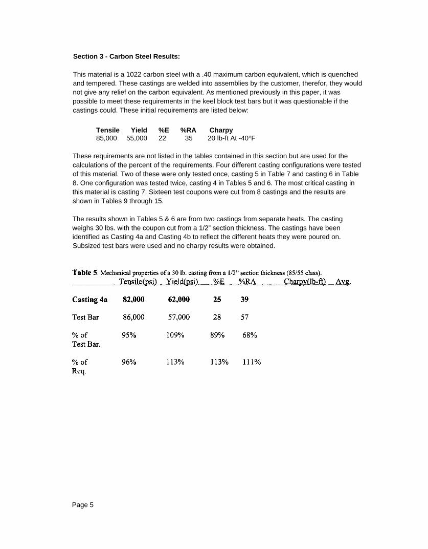
Section 3 - Carbon Steel Results:
This material is a 1022 carbon steel with a .40 maximum carbon equivalent, which is quenched and tempered. These castings are welded into assemblies by the customer, therefor, they would not give any relief on the carbon equivalent. As mentioned previously in this paper, it was possible to meet these requirements in the keel block test bars but it was questionable if the castings could. These initial requirements are listed below:
Tensile Yield %E %RA Charpy 85,000 55,000 22 35 20 lb-ft At -40°F
These requirements are not listed in the tables contained in this section but are used for the calculations of the percent of the requirements. Four different casting configurations were tested of this material. Two of these were only tested once, casting 5 in Table 7 and casting 6 in Table 8. One configuration was tested twice, casting 4 in Tables 5 and 6. The most critical casting in this material is casting 7. Sixteen test coupons were cut from 8 castings and the results are shown in Tables 9 through 15.
The results shown in Tables 5 & 6 are from two castings from separate heats. The casting weighs 30 lbs. with the coupon cut from a 1/2” section thickness. The castings have been identified as Casting 4a and Casting 4b to reflect the different heats they were poured on. Subsized test bars were used and no charpy results were obtained.
Page 5

The yield strength in the casting exceeded the test bar results. This can be attributed to the thinner cross section of the casting. The tensile strength in the castings was lower than the test bar which was expected and will be discussed later in the paper.
Table 7 shows the results from a 180 lbs casting which is the largest part cast in this material. The test coupons were taken from a 2” section directly below a 6” diameter exothermic riser. The casting has been identified as casting 5.
As expected the mechanical properties of the casting were lower than the reported test bar results. The yield strength, % elongation, % reduction of area and charpies exceeded the customers requirements but like casting 4a and 4b, the tensile strength was below the required 85,000 psi.
Page 6

Table 8 shows the results from a 17 1bs casting with a 1” section thickness. The casting has been identified as casting 6.
Even though this is the lightest casting made in this material, these results are the most informative. It is indicative of why mechanical properties should not be taken from castings. As seen in the results the casting did not achieve the ductility standards in the static test, however, the results obtained in the charpy test prove that the material is ductile. Upon further investigation the bar was found to have some shrink, class CA2, at the point of fracture. This shrink caused the tensile to be low and greatly effected the percent elongation and reduction in area. The yield requirement, which is the most critical property to the design, was met even with this defect.
Tables 9 through 16 are all tests from the same casting configuration. This casting is the most critical part to the customer. It weighs 125 lbs. with two different section thickness’, a 1” plate section with 2” sections protruding 90° from the plate. Out of these 8 castings 3 tests were taken from the 1” plate section with 13 taken from the 2” section. As it turns out the 2” section is the highest stressed area of all the parts made of this material.
Page 7
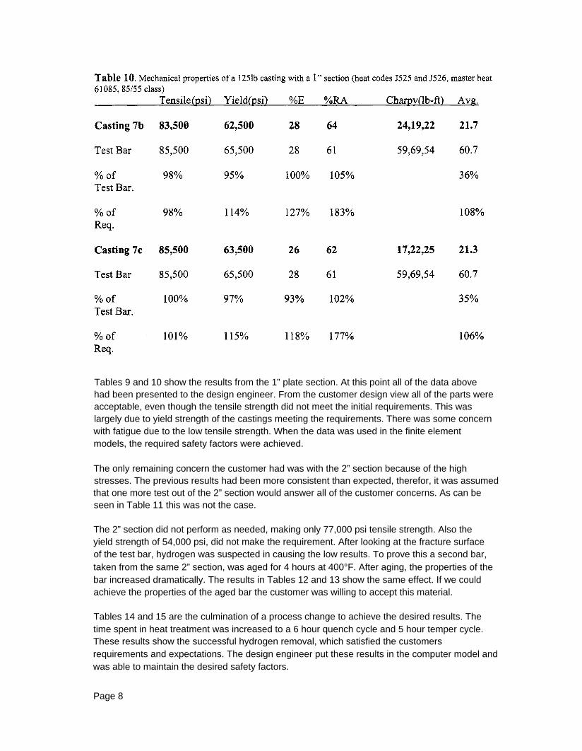
Tables 9 and 10 show the results from the 1” plate section. At this point all of the data above had been presented to the design engineer. From the customer design view all of the parts were acceptable, even though the tensile strength did not meet the initial requirements. This was largely due to yield strength of the castings meeting the requirements. There was some concern with fatigue due to the low tensile strength. When the data was used in the finite element models, the required safety factors were achieved.
The only remaining concern the customer had was with the 2” section because of the high stresses. The previous results had been more consistent than expected, therefor, it was assumed that one more test out of the 2” section would answer all of the customer concerns. As can be seen in Table 11 this was not the case.
The 2” section did not perform as needed, making only 77,000 psi tensile strength. Also the yield strength of 54,000 psi, did not make the requirement. After looking at the fracture surface of the test bar, hydrogen was suspected in causing the low results. To prove this a second bar, taken from the same 2” section, was aged for 4 hours at 400°F. After aging, the properties of the bar increased dramatically. The results in Tables 12 and 13 show the same effect. If we could achieve the properties of the aged bar the customer was willing to accept this material.
Tables 14 and 15 are the culmination of a process change to achieve the desired results. The time spent in heat treatment was increased to a 6 hour quench cycle and 5 hour temper cycle. These results show the successful hydrogen removal, which satisfied the customers requirements and expectations. The design engineer put these results in the computer model and was able to maintain the desired safety factors.
Page 8

Page 9

As Table 14, the 2” section, with the extended heat treatment met the design requirements. No signs of hydrogen were evident in these test bars. After aging the bars did not increase as had been the case when the hydrogen was present. Table 15 shows the properties of the 2” section are repeatable with the modified heat treatment.
Page 10

Summary:
The CA6NM and 105/85 materials have enough alloying that the section thickness’ and casting geometry’s for this project do not adversely effect their mechanical properties. The test bars do represent the properties in the castings.
The thinner section casting, 1/2”, had a higher yield strength but the tensile strength was lower.
The heaviest casting achieved 94% of the tensile and yield achieved from the test bar.
Shrinkage had little effect on the yield strength, which is the most important factor from the designers point of view. This shows that castings, even with shrinkage in them, are very reliable and structurally sound. A question was raised concerning the fatigue limit because of the low tensile strength. Fatigue failures normally occur from surface defects. Since shrinkage normally occurs in the center of a section it is in the lowest stress area of the section. Also, if tensile could be taken from the outer surface, the strength would be higher. This would result in a better fatigue limit.
The way castings are rigged, the configuration, section size, material and other unknown factors can greatly effect the mechanical properties within a castings. Casting 7 had a difference of 8000 psi (9.5%) in tensile, 9750 psi (15.5%) in yield, 8 percentage points (30%) in elongation, and 31.5 percentage points (50%) in reduction of area when comparing the 1” plate section to the 2” section, even in a small (125 lb) casting.
The results show that hydrogen does diffuse out of castings. This is shown in the results of the aged bars J525 and J526, Tables 11 and 12. Its is also show in the results of bars taken from the castings with the increase in heat treatment but were not aged before testing.
The charpy results from the castings met the 20 ft-lbs. requirement but were 46% lower then the results obtained from the test bars in the carbon steel materiel.
Page 11

Conclusion:
From Table 16, excluding shrinkage and hydrogen effects, the castings averaged 3% lower than the test bars for the tensile and yield in carbon steel. The elongation was 6% lower and the reduction of area was 11% lower.
It is called out by the Association of American Railroads Mechanical Division in specification M201-92, which was adopted 1923 and revised 17 times since, section 7.1.1 that at the manufacturing option to attach the test coupon are from keel blocks. But in section 7.2.5 it outlines that if test specimens are cut from castings they only must have at least 80% of the tensile and yield properties. This testing of castings is to be agreed to at the time the parts are purchased between the foundry and the purchasing company. (1)
When this point was first brought up to the design engineer, the notion was to raise the test bar requirements by 80%. But by using all the data presented in this paper and several discussions about the excellent properties of steeI castings the 80% increase was not necessary. Actually, no increase or change was needed to satisfy the design criteria.
References:
[1] Association of American Railroads, “Specification M-20 1-92 Steel Castings,” Manual of Standards and Recommended Practices. 1923 Revised 1933,1934,1936,1945,1946,1947, 1952, 1953,1960, 1962, 1966, 1979,1981, 1982, 1983, 1984, 1992
Page 12