mastergenerator g3800 x036 - dupline g3800x036_eng.pdf · mastergenerator g3800 x036 operation...
TRANSCRIPT

Mastergenerator
G3800 X036
Operation Manual
Last Update: August 2006
Du line®
Fieldbus Installationbus

G 3800 X036 Operation Manual August 2006
2 © 2006 Carlo Gavazzi Industri A/S. All rights reserved
Table of Contents 2
1. Introduction 41.1. Start-up 4
1.1.1. Hardware requirements 41.1.2. Installation 41.1.3. Start-up of program 4
1.2. Functions in the main window 51.2.1. File menu 51.2.2. Edit menu 61.2.4. Tools menu 71.2.3. Options menu 71.2.5. Help menu 111.2.6. Configuration of channel functions 12
1.3. Basic Setup 13
2. Objects 152.1. General 152.2. Standard objects 15
2.2.1. Blank / Indicator 152.2.2. Push-button 162.2.3. Toggle switch 182.2.4. Timer/Recycler 202.2.5. Real-time clock / Night setback 232.2.6. Master function 252.2.7. Light Synch 282.2.8. Guide Light 282.2.9. Multigate 302.2.10. Thermostat 31
2.3. Special objects 322.3.1. Analog sensors 322.3.2. Motion detector 362.3.3. Dimmer functions 382.3.4. Light functions 412.3.5. Temperature Control 432.3.6. Wireless Base 45
2.4. Alarm functions 472.4.1. Overview 472.4.2. General features 472.4.3. ISA Alarm 482.4.4. Smoke Alarm 532.4.5. Intruder Alarm 582.4.6. Water Alarm 642.4.7. Common Siren 69
2.5. Roller blind control 702.5.1. Decentralized roller blind up-down function 702.5.2. Roller blind master 74
2.6. Counter and Multiplexer 772.6.1. Multiplexer (transmission of counter values) 772.6.2. Multiplexer (transmission of analog values) 79
2.7 Reference to data from other Dupline networks 812.7.1. General 812.7.2. External reference 812.7.3. Read external input 822.7.4. Status Indicator 83
Table of Contents

G 3800 X036 Operation Manual August 2006
© 2006 Carlo Gavazzi Industri A/S. All rights reserved 3
3. Logic Setup 843.1. Introduction 843.2. The dialog - logic functions 84
3.2.1. Setup 843.3 Application 85
3.3.1. Setups and Functions 853.3.2. Inversion and Edge Triggering 863.3.3. Using the on-board I/Os 873.3.4. Internal processing of the logic setups 87
3.4. Notes and Documentation 873.4.1. Input definitions 87
4. Communication Ports 884.1. General 884.2. Protocol 884.3. COM1 884.4. COM2 884.5. RS485 894.6. Setup of Communication Ports 90
5. GSM Modem functions 925.1. SMS Setup 925.2. Event-based SMS messages 945.3. SMS Control commands and Requests for Dupline data 95
6. Data Logging Functions 966.1. General 966.2. Dupline-Online 966.3. Dupline-Online Transmission Media 97
6.3.1. Using GSM Modem 976.3.2. Using the Internet 97
6.4. Event-based logging 976.5. Time-based logging 98
6.5.1. Introduction 986.5.2. Time-based logging of Analink channels 986.5.3. Time-based logging of Counters 996.5.4. Time-based logging of Multiplexed Analog data 100
6.6. Export of the Configuration to the Dupline-Online Webserver 1016.7. Dupline-Online Data Security 101
7. Radio Modem Functions 1027.1. General 1027.2. Setup of Radio Modem Central 1037.3. Setup of Radio Modem Substation 104
Appendix A 105
Appendix B - ModBus Functions 106
Appendix C - RS485 Communications 112

G 3800 X036 Operation Manual August 2006
4 © 2006 Carlo Gavazzi Industri A/S. All rights reserved
1. IntroductionThe G3800 tool has been designed for configuration of the Mastergenerators G3800x015, G3800x016 andG3800x036. All functions in the mastergenerator are represented by graphic symbols, and all function related parametersand comments are setup locally in the PC, and then transferred to the Mastergenerator through RS232.Likewise, data from the Mastergenerator can be uploaded and modified.The Mastergenerator firmware and configuration tool are subject to changes, as new functions are added con-tinuously. Please check the download section at our hompage www.dupline.com for the latest updates.
1.1. Start-up
1.1.1. Hardware requirements• The program operates under Windows 95/98/2000/xp and NT and requires at least:• 400Mhz Pentium II processor with 32 Mbytes Ram or higher• A free serial port (Com1 or Com2)• 10 Mbytes hard disk for installation• Screen resolution of 800 x 600 pixels, 256 colours or higher• Mouse or other pointing tool desirable, but not necessary
1.1.2. InstallationInsert the CD rom and run the program “Setup.exe”. This will guide you through the installationprocess. After installation, the program can be started by clicking G3800xxxxTool.
1.1.3. Start-up of programWhen G3800xxxxTool is started, two windows will open:
To the left, the main window showing the 128 addresses available in Dupline and the menus. To the right, theproperties window, which for each function shows the parameters related to the selected functions.A third window may appear, which also contanis configuration entries, or functions for maintenance and test.

© 2006 Carlo Gavazzi Industri A/S. All rights reserved 5
G 3800 X036 Operation Manual August 2006
1.2. Functions in the main window
1.2.1. File menu
The file menu contains the usual functions:
Menu Item: Explanation
New: Start from the beginning with default data
Open: Open existing file
Save: Save file
Save As: Save file under new name
Write Mastergenerator: Download the present configuration file to the Mastergenerator
Read Mastergenerator: Read the configuration file from the Mastergenerator
Export configuration: 1) Create Dupline-Online configuration file to be exported to the Central Server during registration (see chapter 6)
Print: The following options are available:Print-out of:Address ListingMaster Channels & multigateReal time ChannelsLogic SettingsSMS SetupInput definitionsExternal References
Exit: Exit program
1) Only selectable for G380xx36

G 3800 X036 Operation Manual August 2006
6 © 2006 Carlo Gavazzi Industri A/S. All rights reserved
Menu Item: Explanation:
Basic Setup: Basic setup of the Mastergenerator
Logic Setup: Configuration of logic functions
Holiday Setup: Setup of holiday period. The holiday setup is active when the current date falls within any of the set time intervals.
SMS Setup Basic setup of the SMS messaging functions facilitated by the built-in GSM modem.
Counter and Mux analog Setup: Basic setup of the multiplex functions required when Counter Modules and Multiplexed Analog Modules are used.
Communication Setup: Configuration of the communication functions available for the two RS 232 ports and the RS485 port of the Mastergenerator.
Analink Log Set-up 1) Basic Set-up for logging of Analink values (see chapter 6)
Mux Counters Log Set-up 1) Basic Set-up for logging of Counter vlaues (see chapter 6)
Mux Analog Log Set-up 1) Basic Set-up for logging of Multiplexed Analog values (see chapter 6)
Input definitions Entry and management of transmitters and their respective addressing.
1.2.2. Edit menu
1) Only selectable for G3800X036

© 2006 Carlo Gavazzi Industri A/S. All rights reserved 7
G 3800 X036 Operation Manual August 2006
Menu Item: Explanation:
Language: Select between available languages. By using the “Select new” menu, other languages can be chosen to appear in the language menu.
Serial port: Selection of serial communication ports from Com 1 to Com 10, for connection of the Mastergenerator.
1.2.3. Options menu
1.2.4. Tools menu

G 3800 X036 Operation Manual August 2006
8 © 2006 Carlo Gavazzi Industri A/S. All rights reserved
1.2.4.2. GTU Test Tool: These tools are used to display the immediate digital status on the Dupline channels.When enabled, control of the Dupline channels is possible as well. This tool provides a good overview of the activity on the Dupline bus and is particularly good when testing the application.
1.2.4.1. Generator firmware: In this menu it is possible to download a new firmware file to the Generator. New firmware files are typically made available when new features are added to the Generator. Three steps need to be carried out:1. Browse to select the desired firmware file.2. Activate the Download button and follow the emerging dialog-boxes. 3. Activate Close button when done.
For firmware version 2,0 and onward, see part 3.3.3.: Using the on-board I/Os
© 2006 Carlo Gavazzi Industri A/S. All rights reserved 9
G 3800 X036 Operation Manual August 2006
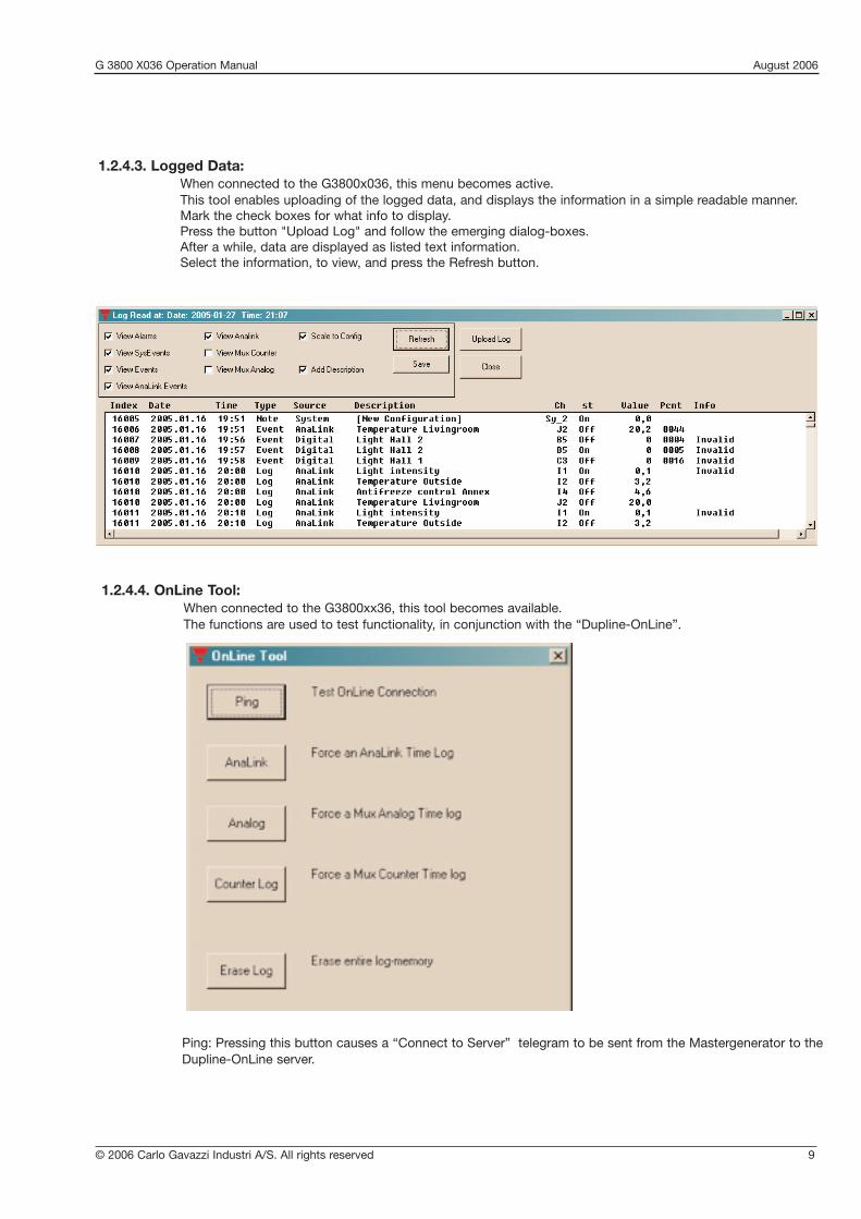
1.2.4.3. Logged Data:When connected to the G3800x036, this menu becomes active.This tool enables uploading of the logged data, and displays the information in a simple readable manner.Mark the check boxes for what info to display.Press the button "Upload Log" and follow the emerging dialog-boxes.After a while, data are displayed as listed text information.Select the information, to view, and press the Refresh button.
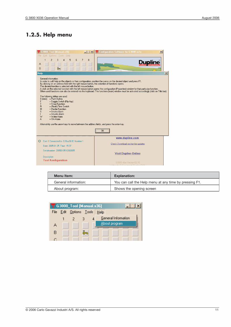
1.2.4.4. OnLine Tool:When connected to the G3800xx36, this tool becomes available.The functions are used to test functionality, in conjunction with the “Dupline-OnLine”.
Ping: Pressing this button causes a “Connect to Server” telegram to be sent from the Mastergenerator to the Dupline-OnLine server.

G 3800 X036 Operation Manual August 2006
10 © 2006 Carlo Gavazzi Industri A/S. All rights reserved
While connection is established, the status may be monitored on the main-window.
AnaLink: Activating this, forces an AnaLink Time log
Analog: Activating this, forces an Mux Analog Time log
Counter Log: Activating this, forces a Mux Counter Time log
The respective logs should be configured in the mastergenerator, in order to make a simulated time-log.
Erase Log: Pressing this, will cause the log-memory in the Mastergenerator to be erased.
Important note: this function will cause the Mastergenerator to be restarted, hence this should only be used while the Dupline wires are disconnected.
No connection
Connection establilshed
G 3800 X036 Operation Manual August 2006
© 2006 Carlo Gavazzi Industri A/S. All rights reserved 11
Menu Item: Explanation:
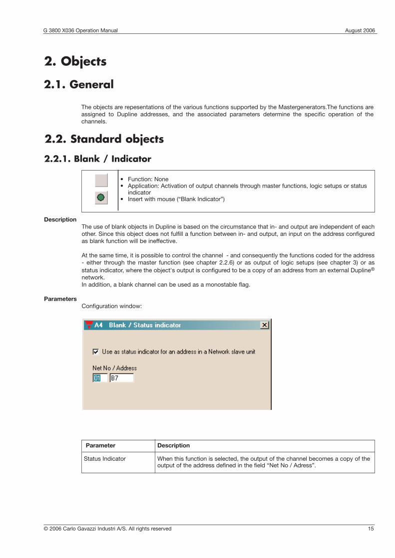
General information: You can call the Help menu at any time by pressing F1.
About program: Shows the opening screen
1.2.5. Help menu

G 3800 X036 Operation Manual August 2006
12 © 2006 Carlo Gavazzi Industri A/S. All rights reserved
1.2.6. Configuration of channel functions
When the basic settings have been made under “Basic Setup”, the functions of the remaining channels to beused are defined as follows:
Activate one of the channels, then click on the right mouse button for pop-up menu. Click on the desired channel function with the left mouse button. The channel is thereby assigned a symbol indicating the selected channel function. Click on the symbol with the left mouse button, and the parameters which can beset for that particular channel function can be viewed in the properties window.
The arrow keys can also be used to select channel function in the pop-up menu. Furthermore, channel function can be selected by clicking on different letters. To see how to select functions by clicking on letters,select the General information menu under Help.
Tool tipWhen the cursor is positioned on an address button, a so-called "ToolTip" appears.The ToolTip indicates the address function, and the user-defined description.
Two "!!" in front of the tool-tip indicates, that the adress also is controlled by a logic function.

G 3800 X036 Operation Manual August 2006
© 2006 Carlo Gavazzi Industri A/S. All rights reserved 13
1.3. Basic Setup
General descriptionThe text window is for entering general information, eg name of user, date of configuration, reference to documentation, etc.
No. of AdressesFor selection of the number of channels desired in the system. The minimum is 16, the maximum is 128 in oneDupline network.
Restore Channel Status upon Power-upWhen this function is selected, the Mastergenerator will memorize the channel status on toggle channels andreal-time channels in case of a loss of power. The Mastergenerator will then restore the output status onthese channels when the power comes back.
The option can not be selected, unless the Generator is connected to the PC.
Channel restore Interval (1/10 Seconds)In order to reduce the total in-rush current when using the "Restore Channel Status upon Power-up" function,it is possible to define a delay between the activations of outputs. The delay is entered in 1/10 Seconds.
Long Activation timeSet-up the time, for how long a 'Long activation' must last, before an activation takes place.Some channel objects, are able to be activated by a long activation from another address. Eg. B2 is a Masterfunction, which reacts on a long activation of B1.B1 may be a toggle switch for normal on/off. Now by holding the B1 for the Long activation time, the Masterfunctionon B2 activates, this gives B1 two functions, and saves one push-button.

G 3800 X036 Operation Manual August 2006
14 © 2006 Carlo Gavazzi Industri A/S. All rights reserved
Enable automatic update of realtime status upon Config-download and System power-upIf this box is checked, the Generator will automatically set the correct status for realtime channels according tothe switch-time settings, provided that the actual Day of the week matches the internal Day of the week of theGenerator. Also, the Generator will only scan the switch times (ON or OFF) for that same day.
Enable Automatic Daylight saving. Central European Time standardIf this box is checked, the Generator will automatically change the time settings 2 times per year according tothe European standard for daylight savings.
Enable RTC Powerline AutocalibrationSelecting Auto-calibrate, will enable the internal Realtime clock to adjust its internal calibration against theMains-supply frequency. In most countries, the Mains-supply frequency is very accurate, and in that case animproved accuracy on the Realtime clock can be achieved.
Syncronize Time to PC date and TimeIf this button is activated when the Generator is connected to the PC, then the PC date and time will be trans-ferred to the realtime clock of the Generator.
G 3800 X036 Operation Manual August 2006
© 2006 Carlo Gavazzi Industri A/S. All rights reserved 15
2.2.1. Blank / Indicator
DescriptionThe use of blank objects in Dupline is based on the circumstance that in- and output are independent of eachother. Since this object does not fulfill a function between in- and output, an input on the address configuredas blank function will be ineffective.
At the same time, it is possible to control the channel - and consequently the functions coded for the address- either through the master function (see chapter 2.2.6) or as output of logic setups (see chapter 3) or as status indicator, where the object's output is configured to be a copy of an address from an external Dupline®
network. In addition, a blank channel can be used as a monostable flag.
ParametersConfiguration window:
• Function: None• Application: Activation of output channels through master functions, logic setups or status
indicator• Insert with mouse (“Blank Indicator”)
2.2. Standard objects
Parameter Description
Status Indicator When this function is selected, the output of the channel becomes a copy of theoutput of the address defined in the field “Net No / Adress”.
2.1. General
The objects are repesentations of the various functions supported by the Mastergenerators.The functions areassigned to Dupline addresses, and the associated parameters determine the specific operation of the channels.
2. Objects

G 3800 X036 Operation Manual August 2006
16 © 2006 Carlo Gavazzi Industri A/S. All rights reserved
2.2.2. Push-button
DescriptionThe push-button function - the most simple object of the Mastergenerator - makes it possible to connect anytype of push-button switch and contact to the Dupline bus. With this function, outputs can indirectly be con-trolled with logic functions.
In this function, the output follows the input signal: the output is activated as long as the input signal is ON(inverted in Normally Closed function).
ParametersConfiguration window of push-button function:
Time characteristics
The output follows the input upon a short delay. In the Normally closed function, the output function is the oppo-site of the input function.
Parameter Description
Inverted function When this function is selected, the output signal is inverted. This means that theoutput is activated as long as the input has not been set.
• Function: Monostable • Application: Connection of push-button switches and contacts for load
switching• Also Normally Closed function
Normally Open Normally Closed
IN IN
OUT OUT

© 2006 Carlo Gavazzi Industri A/S. All rights reserved 17
Object Function Channel
In-/outputs
Relay output Lamp A1
Switch Light switch A1
Configuration
Push-button function Light control A1
Application Example
Task: A lamp is to be switched on and off by means of a switch.
Solution: Use for example the universal input module to provide the input signal and configure one of theinputs for address A1. Assign the same address to one of the outputs of a relay module. Finally,configure channel A1 in the Mastergenerator as push-button function.
G 3800 X036 Operation Manual August 2006

G 3800 X036 Operation Manual August 2006
18 © 2006 Carlo Gavazzi Industri A/S. All rights reserved
Parameter Description
Intruder alarm When this function is selected, the input will send a signal to the intruder alarmsystem to cause the siren to start. This requires that an intruder alarm is configured, and that the Intruder alarm is armoured.
Disable Address When the address here is activated, the signal sent to the Intruder alarm is disabled, in this manner more alarm-zones may be created.
React upon Long When the address here has been activated for the 'Long Activation time', theactivation of switch-function will execute.
2.2.3. Toggle switch
DescriptionThe toggle switch is used for the basic Light-switching.The status of the addres changes to its opposite upon every new activation.
ParametersConfiguration window of the toggle switch function:
Time characteristics
The first triggering of the input switches the output on, the second triggering switches the output off again.
• Function: Bistable Flip-Flop• Application: Connection of switches and contacts for load switching• Can be used in intruder alarm systems
IN
OUT

© 2006 Carlo Gavazzi Industri A/S. All rights reserved 19
Object Function Adress
In-/outputs
Relay output Lamp A1
Switch Light switch A1
Configuration
Toggle switch function Light control A1
Application Example
Task: A lamp is to be switched on and off by means of a conventional switch.
Solution: Use for example the universal input module to provide the input signal and configure one of theinputs for address A1. Assign the same address to one of the outputs of a relay module. Finally,configure channel A1 in the Mastergenerator as switching function.
G 3800 X036 Operation Manual August 2006
G 3800 X036 Operation Manual August 2006
20 © 2006 Carlo Gavazzi Industri A/S. All rights reserved
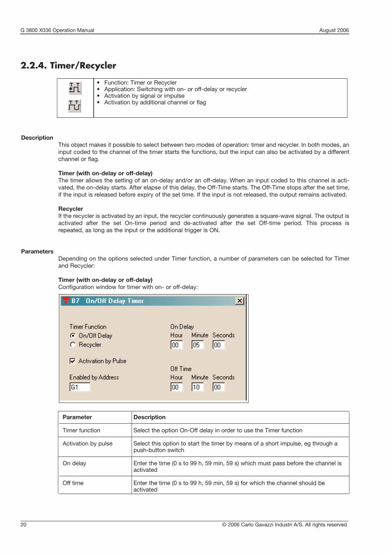
2.2.4. Timer/Recycler
DescriptionThis object makes it possible to select between two modes of operation: timer and recycler. In both modes, aninput coded to the channel of the timer starts the functions, but the input can also be activated by a differentchannel or flag.
Timer (with on-delay or off-delay)The timer allows the setting of an on-delay and/or an off-delay. When an input coded to this channel is acti-vated, the on-delay starts. After elapse of this delay, the Off-Time starts. The Off-Time stops after the set time,if the input is released before expiry of the set time. If the input is not released, the output remains activated.
RecyclerIf the recycler is activated by an input, the recycler continuously generates a square-wave signal. The output isactivated after the set On-time period and de-activated after the set Off-time period. This process is repeated, as long as the input or the additional trigger is ON.
ParametersDepending on the options selected under Timer function, a number of parameters can be selected for Timerand Recycler:
Timer (with on-delay or off-delay)Configuration window for timer with on- or off-delay:
Parameter Description
Timer function Select the option On-Off delay in order to use the Timer function
Activation by pulse Select this option to start the timer by means of a short impulse, eg through apush-button switch
On delay Enter the time (0 s to 99 h, 59 min, 59 s) which must pass before the channel isactivated
Off time Enter the time (0 s to 99 h, 59 min, 59 s) for which the channel should be activated
• Function: Timer or Recycler• Application: Switching with on- or off-delay or recycler• Activation by signal or impulse• Activation by additional channel or flag

© 2006 Carlo Gavazzi Industri A/S. All rights reserved 21
Time characteristics
On- Off-delay timer, started by pulse.
Delay On Delay Off
The on-delay starts upon deactivation of the input. After elapse of the On-delay, the Output turns on, and theOff-time is started.After elapse of the Off-time the output switches off again.
Repeating the activation-pulse while the output is Off will restart the On-delay.
Repeating the activation-pulse while the output in On will restart the Off-time.
Parameter Description
Enabled by address Entering of an additional adress (A1..P8) or flag which will also enable the timerfunction. To prevent locking, the channel assigned to the timer itself must not beused.If the additional signal is an impulse, select the option Activation by pulse.
Recycler
Configuration window for recycler
Parameter Description
Timer function To select the Recycler function, select “Recycler”
On-time Entering of the time (1 s to 99 h, 59 min, 69 s) for which the output is On duringrecycling
Off-time Entering of the time (0 s to 99 h, 59 min, 59 s) for which the output is Off duringrecycling
Enabled by address Entering of an additional channel or flag which will also enable the recycler. Toprevent locking, the channel assigned to the recycler itself must not be used.
IN
OUT
G 3800 X036 Operation Manual August 2006

G 3800 X036 Operation Manual August 2006
22 © 2006 Carlo Gavazzi Industri A/S. All rights reserved
Object Function Adress
In-/outputs
Relay output Bathroom light A1
Switch Light switch A1
Relay output Bathroom fan A2
Configuration
Toggle switch function Light control A1
Timer Fan control A2
Application Example
Task: A fan in a bathroom is to start 5 min after the light has been switched on and run for 10 min.
Solution: The lighting is activated by a push-button connected to a sensor module (for example a univer-sal input module) and configured for address A1 as a toggle switch function. An output of a relaymodule is assigned the same address and activates the lighting. A second channel A2 is con-figured as Timer and activated by the above-mentioned push-button. An additional channel ofthe output module is also assigned the address A2 and activates the fan.
Recycler
The impulse is generated upon activation of the input. A pulse cycle consists of the On-timeand the Off-time. When the input is switched off, the pulse cycle stops.
IN
OUT
By use of the additional trigger A1, the timer starts when the light is switched on.

© 2006 Carlo Gavazzi Industri A/S. All rights reserved 23
2.2.5. Real-time clock / Night setback
DescriptionThe real-time clock enables on- and off-switching of loads in relation to the internal time setting of theMastergenerator. It is possible to pre-define up to four switch-on and switch-off times for each clock on freelyoptional weekdays and holidays.
The Night setback is merely another icon to destinguish a specific purpose of the real-time function
ParametersConfiguration window of real-time clock function:
• Function: Real-time clock with week and holidays• Application: Real-time-controlled switching• Also applicable as switching function• Holiday setting can be performed centrally for all clocks
Parameter Description
Switch-on time Time at which the channel is to switch on
Switch-off time Time at which the channel is to switch off
Days of week Day(s) on which the switching time indicated to the left applies(M: Monday, T: Tuesday, W: Wednesday, T: Thursday, F: Friday, S: Saturday, S: Sunday)
If “H” is activated, the clock also switches on holidays. In this case, the corresponding days must be entered under <Edit><Holiday setup>.
React upon Long When the address here has been activated for the 'Long Activation time', theactivation of switch-function will execute.
G 3800 X036 Operation Manual August 2006

G 3800 X036 Operation Manual August 2006
24 © 2006 Carlo Gavazzi Industri A/S. All rights reserved
Time characteristics
IN
OUT
Application Example
Task: A lamp is to be switched on and off by means of a real-time clock.
Solution: Assign adress A1 to one of the outputs of a relay module. Then configure A1 in the MCG as areal-time function.Make the settings for “Switch on”, “Switch off” and “Days of week”. Now the lamp is controlled by the real-time function.
t1: The real-time clock activates the output at the pre-defined time without affecting the input channel.
t2: By activation of the input, the output switches off directly.
t3: By activating the input once more, the output switches on again.
t4: At the set Switch off time, the output is always deactivated.
t5: The output can always be activated again through the input.
Object Function Channel
In-/outputs
Relay output Outdoor lamp A1
Configuration
Real-time function Light control A1
G 3800 X036 Operation Manual August 2006
© 2006 Carlo Gavazzi Industri A/S. All rights reserved 25
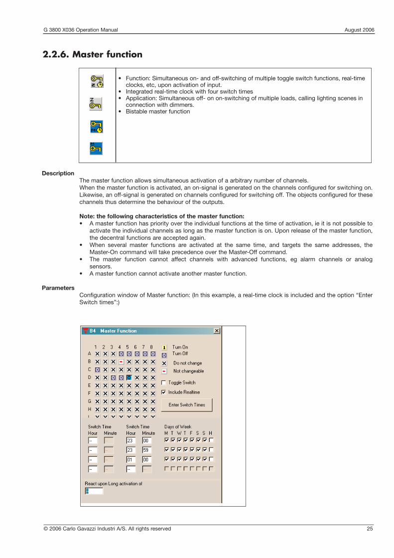
2.2.6. Master function
DescriptionThe master function allows simultaneous activation of a arbitrary number of channels.When the master function is activated, an on-signal is generated on the channels configured for switching on.Likewise, an off-signal is generated on channels configured for switching off. The objects configured for thesechannels thus determine the behaviour of the outputs.
Note: the following characteristics of the master function:• A master function has priority over the individual functions at the time of activation, ie it is not possible to
activate the individual channels as long as the master function is on. Upon release of the master function,the decentral functions are accepted again.
• When several master functions are activated at the same time, and targets the same addresses, the Master-On command will take precedence over the Master-Off command.
• The master function cannot affect channels with advanced functions, eg alarm channels or analog sensors.
• A master function cannot activate another master function.
ParametersConfiguration window of Master function: (In this example, a real-time clock is included and the option “EnterSwitch times”:)
• Function: Simultaneous on- and off-switching of multiple toggle switch functions, real-time clocks, etc, upon activation of input.
• Integrated real-time clock with four switch times• Application: Simultaneous off- on on-switching of multiple loads, calling lighting scenes in
connection with dimmers.• Bistable master function

G 3800 X036 Operation Manual August 2006
26 © 2006 Carlo Gavazzi Industri A/S. All rights reserved
Tip: Entire address groups can be changed by clicking on the right mouse button.
Time characteristics (without toggle function selected)
IN
OUT
Switchedoutputs
Toggle switchfunction
Push-buttonfunction
The master function remains active until the input is switched off. In the above example, the outputs switch on,and - in the case of a push-button function - remain on, until the master function switches off again.
Parameter Description
Address matrix Mark the addresses to be switched on by the master function with “1” and theaddresses to be switched off with “0”.*Addresses marked with “x” are not affected. Addresses which are automaticallymarked with a red line cannot be controlled by a master function, eg. master functions, roller blind controls, etc.
Toggle switch If this function is selected, the master function address behaves like a "ToggleSwitch". The addresses controlled by the Masterfunction, will now be able to beturned on and off, by the same Masterfunction. If the Masterfunction addres is off, the next activation will be an ON-command.The ON-command is sent to all addresses marked with a "1" Addresses in the matrix marked with "0" will turn OFF.
Include Real-time A real-time clock is included to time-control the master function. The field “EnterSwitch times” appears.
Enter Switch times Click here to open or close for the entry of switch times
Real-time clock Normally, the real-time clock for time-control of the master function behaves inthe same way as the object “Real-time clock”. See chapter 2.2.5. Real-time clockfor further details.
Unlike a separate real-time clock, the built-in real-time clock only generates oneswitching impulse. This is particularly important to bear in mind when the masterfunction is to control push-button functions, since the switch signal has a veryshort duration.
As a Flip-Flop Master The real-time function operates both ON-switching and OFF-switching. Thisenables simultaneous ON- and OFF-switching of multiple channels. The channelsmarked with “1” switch on when the master is activated and switch off upondeactivation. The channels marked with “0” behave in the opposite way.
React upon Long When the address here has been activated for the 'Long Activation time', theactivation of switch-function will execute.

© 2006 Carlo Gavazzi Industri A/S. All rights reserved 27
Object Function Adress
In-/outputs
Push-button input Master on A1
Push-button input Master off A2
Push-button input Push-button for call C1Hall light
Relay outputs Lamps C1..C4
Configuration
Master function Master on A1 turns on C1,C2, C3 and C4
Master function Master off A2 turns on C1 and turns off C2,C3 and C4
Toggle switch function Lamps C1..C4
Application Example
Task: The master function is to control four lamps in a building- Master on: Switches all lamps on - Master off: Switches all lamps off- Both master functions turn on a surveillance light in the hall
Solution: Two push-buttons are configured on addresses A1 to A2 to initiate the master function for theOn and The Off.One pushbutton controlls the Light in the Hall
G 3800 X036 Operation Manual August 2006

G 3800 X036 Operation Manual August 2006
28 © 2006 Carlo Gavazzi Industri A/S. All rights reserved
2.2.8. Guide Light
* Function: Guide light.* controllable Indicator, inverse function* Select with mouse
DescriptionThe Guide Light object is designed to ease indications for Dupline pushbutton switches with LED indications.The object reads the address of the pushbutton, and output its status to the address of the LED indicator. Wheninverted function is selected, the Output acts as ‘Guide Light’, Led on, when switch is off.The output may be controlled by a disable address, which eases control of the object.
ParametersConfiguration window of the Guide Light function:
2.2.7. Light Synch
* Function: Transfer of light intensity signal* Constant light function* Select with mouse
DescriptionThe Light Synch function is needed to synchronize the transfer of the light-intensity signal from the light sensor type G82102220 to the dimmer type G34485239.

© 2006 Carlo Gavazzi Industri A/S. All rights reserved 29
Parameter Description
Input address Enter the address to be monitored
Disable address Entering of an additional channel (A1..P8) or flag (W1..Z8) which will disablethe output function. To prevent oscillation, the channel assigned to the Guide Light itselfmust not be used.
Inverted Function When this function is selected, the output signal is inverted. This means that the output is activated as long as the input has not been set.
Application Example
Task: A guide light function for a switch.
Solution: Use for example the universal input module to provide the input signal and configure oneof the inputs for address A1. Configure channel A1 in the Mastergenerator as push-button function.
Assign address A2 to one of the outputs of a relay module. Finally, Configure channel A2 in the Mastergenerator as guide Light function.Enter Input Address to A1 and check the Inverted Function.
Object Function ChannelIn-/ outputsRelay Output Lamp A1Relay Output Guide Light A2Switch Light switch A1Configuration Push-button function Light control A1Guide Light Indication A2
G 3800 X036 Operation Manual August 2006

G 3800 X036 Operation Manual August 2006
30 © 2006 Carlo Gavazzi Industri A/S. All rights reserved
Parameter Description
Matrix field Select the Multi-gate input signals AND all 1’s All the selected 1’s, must be active, to activate the object’s outputOR all 1’s One or more of the selected 1’s, must be active, to activate the object’s
outputEqual both 1’s and 0’s The selected 1’s and 0’s must match exactly, to activate the object’s
outputInverted Function When this function is selected, the output is inverted. This means that the
output will deactivate when the matching condition becomes True
2.2.9. Multigate
* Function: Multiple input And, Or and Compare* Logic operator* Select with mouse
DescriptionThe Multigate object is designed to ease monitoring of multiple channels. The object reads the current statusof all addresses. This actual status is then held against the selected addresses which form its logic inputs. Theselected logic operation of the object is executed, and the result hereof is led to the objects output.
ParametersConfiguration window of the Multigate:

© 2006 Carlo Gavazzi Industri A/S. All rights reserved 31
Object Function Channel
In-/ outputs
Relay Output Pump A1
Temperature AnaLink temperature B1
Temperature AnaLink temperature B2
Temperature AnaLink temperature
Configuration B3
AnaLink Temperature 3 temperature measurements B1,B2 and B3
MultiGate Controls the Pump A1
Application Example
Task: A pump needed to be started, upon request from 3 different temperature sensors.
Solution: Use for example 3 AnaLink temperature transmitter, coded for B1,B2 and B3.Assign address A1 to one of the outputs of a relay module.
Configure channel A1 in the Mastergenerator as a Multigate with Or function. Set-up ‘One’s’ in the MultiGate matrix B1,B2 and B3.Configure the 3 AnaLink sensors, to activate their output when temperature is below eg. 18 degrees.
2.2.10. Thermostat
Description: The Thermostat operates similar to the Push-button function, but is used to indicate an address occupied by a digital thermostat transmitter.
Parameters: None
* Function: Monostable* Application: Indicate address used for Digital Thermostat transmitter
G 3800 X036 Operation Manual August 2006

G 3800 X036 Operation Manual August 2006
32 © 2006 Carlo Gavazzi Industri A/S. All rights reserved
2.3. Special objects
2.3.1. Analog sensors
DescriptionThe objects of the analog sensors offer the possibility of integrating analog measuring devices in Dupline andprocessing their values. It is possible to select among four types of sensor functions.
Measuring sensorGeneral sensor object, with which all the other sensor types can be integrated (the following sensors, such asthe light sensor, are indicated by different icons and the measuring ranges are partly pre-defined).
Since all sensors operate in the same way, their functions are illustrated by means of the general measuringsensor.
Light sensorThis pre-defined object for the light sensor operates in the same way as the measuring sensor, but has a different icon and the preset measuring range of 0.1 to 100,000 Lux.
Wind sensorThis sensor object is intended for the integration of a wind meter (anemometer), but requires a conversionmodule. Apart from that, this object operates like the measuring sensor.
Temperature sensorThis object also operates in the same way as the measuring sensor, but has its own icon for easy recognition.
General informationChannels for analog transmission operate in the same way as other switching channels. For example, theycannot be switched with switches that operate on the same channel. This means that an additional channel isneeded when for example a sensor only is to be switched manually and only at a certain time.
Furthermore, analog values cannot be processed by means of flags. Instead, it is possible to configure anynumber of analog sensors so that they relate to the same “source value”.
• Function: Transmission and output of analog values (from temperature, light and other sensors) to perform switching functions
• Application: Display of analog (AnaLink) values on text display/touchscreen: load switching (for example heating elements, lamps, roller blinds) in relation to temperature or outdoor light, etc.
• Readout at any time of analog values in relation to external values• Up to two switching ranges can be defined on each channel• Disabling of switching operations through an additional channel or flag• Select with mouse “Analink Sensor”

© 2006 Carlo Gavazzi Industri A/S. All rights reserved 33
The following table gives an overview of all parameters:
Parameter Description
Function Select the function of an ordinary measuring sensor, light sensor, wind or temperature sensor. Basically, all functions operate in the same way.
Disable address When the channel or flag entered here is activated, all switching operations ofthe sensor are disabled.
Control output Select this function if the sensor are used to activate a relay on thesame address.
If the analog value is to be read by other Dupline modules or interfaces for, thenthe contol output should be left un-checked.
Invert limits This option inverts the switching function in relation to the limit values.
Alternative input Select this option to get the Analink value from another adress set by the Net No/ Adress
Sensor input range The upper and lower limit values of the sensor. For example, the lower valuecould be -30 ˚C, while the upper value could be 60 ˚C.
Note: The entry of each value must be confirmed with the Enter-key.
Net No / Adress Enter the address, from where the object are to fetch its AnaLink value.
Off < Limit These are the switching limits of the sensor object. If the option “Invert limits” isOn > Limit not selected, the limit values appear as described, ie if the values “17.0” and or “20.0” are entered, the channel switches off when the actual value is below 17.0 On < Limit and switches on when the actual value is above 20.0.Off > Limit
When the limit values are inverted, the sensor switches on when the actual valueis below 17.0 and switches off when the actual value is above 20.0. This settingis typical for a heating control system.
The limit values are only active, when the address enabling a second pair of limitvalues is not switched on.
Note: The entry of each value must be confirmed with the Enter-key.
Enable limit 2 This option is selected in order to enter a second pair of limit values, for instancefor night setback.
Off < Limit The second pair of limit values makes it possible to enable a different switchingOn > Limit operation through a different address - “Enabled by address”. If “Enabled by or address” is activated, the second pair of limit values will apply instead of the first On < Limit pair. Off > Limit
The second pair of limit values can also be inverted by the “Invert limits” option.
Note: The entry of each value must be confirmed with the Enter-key.
Enabled by address When the selected channel or flag is not active, the first pair of limit values willapply, when it is active, the second pair will apply.
The value can be overwritten at any time and deleted by the Delete-key.
G 3800 X036 Operation Manual August 2006

G 3800 X036 Operation Manual August 2006
34 © 2006 Carlo Gavazzi Industri A/S. All rights reserved
Time characteristics
Sensor for display of measuring valuesIn this application, the displayed value follows the actual value after a short delay.
Note: The final measuring value is reached within 30 seconds from power up of the system, or if a new sensor is attached to the Dupline.
Sensor as switching channelThe time characteristics of the sensors are here illustrated by the example of a temperature sensor: the uppercurve shows the room temperature, the curve in the middle shows the Disable address, and the lower curveshows temperature sensor as switching channel.
t
t
tt2t1 t5t3 t4 t6
t1: The room temperature drops to the value entered for On > Limit, eg 21°C. Since no Disable Addressis entered, the object “Temperature sensor” switches the channel on.
t2: The temperature reaches the value entered for Off < Limit, eg 17°C. Since a Disable Address is still not entered, the channel assigned to the “Temperature sensor” object switches off.
t3: The room temperature reaches the lower limit value again, and the object switches on.
t4: The Disable Address (channel or flag) is activated, for example through a toggle switch.
t5: Although the upper limit value is reached, the object does not switch the output on, because the Disable address is active.
t6: The temperature sensor switching channel does not switch off, until the Disable address is deactivated.
Temperature sensor
Disable address
Room temperature:
Value for Off > Limit
Value for On < Limit

© 2006 Carlo Gavazzi Industri A/S. All rights reserved 35
Object Function Channel
In-/outputs
Temperature sensor Temperature A2
Relay output Heating valve A3
Configuration
Analog sensor: Transmission of A2Temperature sensor analog value
Analog sensor: Analog signal out- A3Temperature sensor put and switching
channel for the relay of the heating valve
Real-time clock Timer for night A4setback
Application Example
Task: A heating element is to keep the room temperature between 19°C and 21°C during daytime. Atnight, the temperature must be lowered by 4°C.
A temperature sensor located in the room is coded for address A2 and displays the temperatureon a Touchscreen.
Solution: Since the analog sensor value on A2 is already needed for displaying the temperature, we assignthe temperature sensor object - and consequently the relay controlled by the heating element -to address A3.
For the night setback, we assign a real-time clock to A4 with the desired switching times. Thereal-time clock serves as an additional address for enabling the second pair of limit values.
G 3800 X036 Operation Manual August 2006

G 3800 X036 Operation Manual August 2006
36 © 2006 Carlo Gavazzi Industri A/S. All rights reserved
DescriptionThe object “Motion detector” makes it possible to include Dupline Passive Infrared Detector (PIR), eg G8910 1127 and conventional motion detectors, which are connected to the Dupline bus via binary inputs.
The PIR detector can have an off time defined and be integrated in the intruder alarm system. Thereby itbecomes possible to avoid false alarms by setting the number of impulses which must be detected within a 10s time window before the alarm starts.
Note: If you want a PIR detector to generate the off time indepedently, the object “Push-button function”should be used.The off time of G8910 1127 can be operated through DIP-switches.
ParametersConfiguration window of Motion detector:
• Function: Includes motion detectors or similar input modules in the Dupline system.• Application: Control of lamps and integration in the intruder alarm system• Off time adjustable from 00 h 00 min 00 s to 99 h 59 min 59 s• Variable number of movement impulses helps to avoid false alarms in the intruder alarm• Select with mouse (“Motion detector”)
Parameter Description
Off time: The time for which the channel remains activated (00.00.00 to 99.59.59) after amotion impulse has occured. Each additional impulse will start the off timeagain. When entering an off time of 00:00:00, the Mastergenerator generates a shortoutput signal indpendently of the duration of the input signal.
Number of pulses The value entered here (1..25) determines how many impulses the motion detector may generate within 10 s, before the alarm starts.When an impulse is detected, the Mastergenerator checks whether the numberof impulses during the past 10 s has exceeded the set number. If this is thecase, an alarm is generated in the connected intruder alarm system.This setting thus reduces the risk of false alarms.
Note: Since the signal output takes place subsequently, an additional impulse isalways needed. This means that when the number of impulses is set to 3, thealarm will go off at the fourth signal. The set off time has no influence on thealarm.
Use in Intruder alarm Click in the check box in order to include the channel in the intruder alarm system.When the Intruder alarm is armed, it will accept the information from the Motiondetector as well, and cause the alarm to acticvate.
Disable Adress The Disable address, when set and active. disables the signal sent to the intruderalarm. The disable address then makes it possible, to use the motiondetectors in different alarmzones.
Invert PIR input signal If the motion detector has a “normally closed” output, then this check should bemarked, to make the function operate correctly.
2.3.2. Motion detector

© 2006 Carlo Gavazzi Industri A/S. All rights reserved 37
Time characteristics
In the following figure, “IN” is the input channel of the motion detector or the contact, while “OUT” is the out-put signal of the same channel. In addtion, the object “Motion detector” has been integrated in the intruderalarm system (whose alarm siren can also be seen in the below diagram). The number of impulses has beenset to “3”.
tP1, tP2, tP3 and tP4 are the points of time at which the motion detector generates a signal. The impulse
duration depends on the characteristics of the detector. TN is the set off time retriggered by the impulses tP2and tP3 and therefore only begins after elapse of the third impulse.
The alarm will not start until after the fourth impulse tP4, and only when the time elapses between tP1 and tP4is less than 10 s.
Alarm siren
IN
OUT
TN
Application Example
Task: A floor lighting is to switch on automatically for 5 minutes with PIR sensor G 8910 1127 and alsoserves as intruder alarm when the house is empty.
Solution: G 8910 1127 must be connected to the Dupline bus and given an address (here A1). In thisexample, increase of the signal transmission time through the DIP switch is to be switched out.Configure both the object “Motion detector” and an output channel of a relay module for addressA1 and additional objects needed for the intruder alarm (Manual armouring, Alarm siren).
Also in this case, the motion detector activates the output module for the lighting directly on address A1. If thealarm system is activated via the manual armouring, the Mastergenerator generates an alarm within 10 s afterthe third impulse.
Additional details about the intruder alarm can be found in chapter 2.4.5.
Tip: If you want to use the Sabotage protection (Normally closed function) of the G 8910 1127, you shouldconfigure the object “Push-button function” for the normally closed function and use the increase of signaltransmission time function provided by the module. In order to include the detector with sabotage protection in an intruder alarm system, you must use the object“Active detector” of the intruder alarm system instead of the Push-button function.
G 3800 X036 Operation Manual August 2006
Input-Armouring Delay This time is taken over by the intrusion alarm as a Desarmouring time. When the motion detec-tor is used in Intruder Alarm and causes an alarm signal, then the alarm siren will go off uponelapse of the Input-Armouring Delay.

G 3800 X036 Operation Manual August 2006
38 © 2006 Carlo Gavazzi Industri A/S. All rights reserved
Description:The Dimmer objects offer the possibility to create advanced light controls using the full potential of the dimmer modules.The dimmer object may consist of merely the Dim up/Down or may be expanded to Include Output status, control channels and several Scenarios.The two types of Dimmers differs, by the fact that the 2X230W (G3448 5234) has 6 scenariosThe 1x600W (G4248 4134) has 8 scenarios, and hence an extra channel for control.The configuration of a dimmer object progresses in successive steps to minimize false entries
The various Dimmer objects selected under Dimmer functions. (Only the 230W type are shown for simplicity)
Dimmer Up/Down: This is the basic dimmer function, used for manually adjustment of lightintensity.
Dimmer Output: This is the Output from the dimmer, indicating that the Dimmer’s output is active.
Dimmer Controls: 2 or 3 control inputs which in combination with the Dimmer up/down are Used to form the control-function of the Dimmer module.
Scenario: This object is the central control for one or more Dimmer modules.
• Function: Setting up Dimmers for both the simple Dim up/down to the more complex scenarios.
• Application: Setting various light scenes to adapt light setting in rooms, according to activity or moods.
• Special objects designed to utilize the full functions of the dimmer modules type G3448 5234 and G4248 4134
• From 6 to 8 difrent scenaries from 0% (off) to 100% (full light)• Scenarios also enables the Dimmers to be controlled by the normal Master function.• Control function by Motion/Proximity detector.
Parameter Description
2.3.3. Dimmer functions

© 2006 Carlo Gavazzi Industri A/S. All rights reserved 39
Dual Output Dimmer Select this when using the 2*230W dimmer type G3448 5234 The dimmer icons appear in Yellow colors.Deselect this when using the 1*600W dimme type G3448 4134The dimmer icons appear in Green colors.
Dimmer Up/Down The Basic dimmer function
The selected address has to match the coding of the Dimmer module’s Dimup/down input.
Control by Motion/ Select this option to enable the dimmer to be controlled by a Motion detector.Proximity detector
Net No / Address Enter the address from where the object is to fetchthe Motion/Proximity Detector’s input signal.
Hour,Minute,Seconds The off-delay associated to the Motion detector
Address of Enter the address of the Dimmer’s Output status. This is essential for the correctDimmer Output operation when combined with a Motion Detector.
Dimmer Output Change the channels function to Dimmer OutputThis selection also changes the channels icon.
The given address has to match the coding of the Dimmer module’s Status Output.
Setting up a Scenario
Step 1
SelectingDimmer Controls
Select "Use in Scenarios", to open the entry of the Dimmer Controls.Enter the channels, to be used for the Dimmer controls.
The Dimmer control channels are created by pressing the OK button.
You must select a new set of controls or select an existing set of controls, thusmore Dimmers may share the same set of Dimmer control channels.
The given addresses has to match the coding of the Dimmer module’s controlinputs.
G 3800 X036 Operation Manual August 2006
G 3800 X036 Operation Manual August 2006
40 © 2006 Carlo Gavazzi Industri A/S. All rights reserved
Combinations of On by Off ByDimmer functions
Manual and activation of the Either Manual or by elapseMotion detector of the Motion detector time
The switch and the Motion detector are located in the same room. The Manual activation switches on or off the function of the Motion detector.
Note: When controlled by Motion detector, the scenarios are still operational.The Motion detector also operates on the various light scenarios. The scenario "All off" will turn off the Manuel switch to prevent the dimmer to turn on by the Motion-detector.
To ensure correct operation of the Dimmer’s, you should not operate the Dimmer-control addresses directly or through Master functions or logic, as this may disturb the function of the Dimmer when con-trolled by Motion detector.
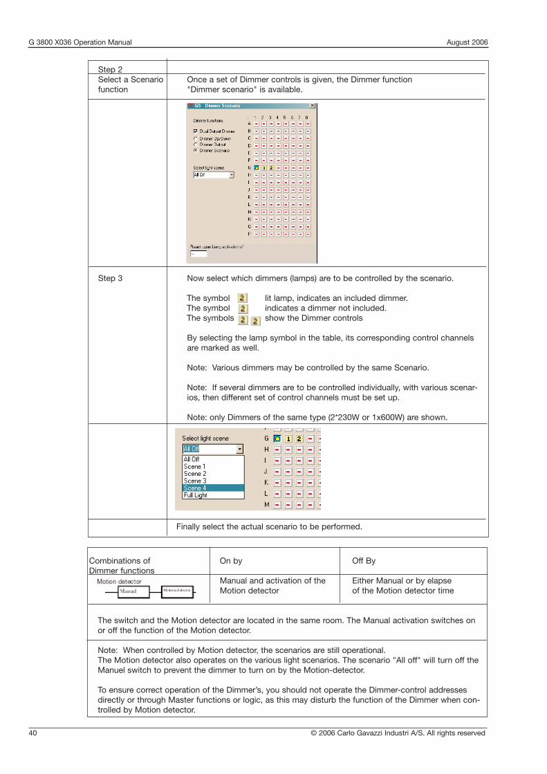
Step 2Select a Scenario Once a set of Dimmer controls is given, the Dimmer functionfunction "Dimmer scenario" is available.
Step 3 Now select which dimmers (lamps) are to be controlled by the scenario.
The symbol lit lamp, indicates an included dimmer.The symbol indicates a dimmer not included.The symbols show the Dimmer controls
By selecting the lamp symbol in the table, its corresponding control channels are marked as well.
Note: Various dimmers may be controlled by the same Scenario.
Note: If several dimmers are to be controlled individually, with various scenar-ios, then different set of control channels must be set up.
Note: only Dimmers of the same type (2*230W or 1x600W) are shown.
Finally select the actual scenario to be performed.

© 2006 Carlo Gavazzi Industri A/S. All rights reserved 41
• Function: Setting up various light control functions• Application: Automatic light functions depending of any combination including Motion/Proximity
switch, Lux meters and Real-time switching, still having the possibility for Manual control.• Complex functions without the need for logic programming.• Channel efficient, all function integrated in the same object.• Manual control by Transmit on same address.
2.3.4. Light functions
Description:The Light function serves a number of selections to create various control options.The Light functions are pre-programmed and take up just one channel, and its functions areperformed from the address input signal, to the output signal on the same address. The object may refer to other addresses to include information from a motion/Proximity Detector and a Light Sensor.
Parameter Description
Motion/Proximity Detector Select this to include a Motion detector in the Light FunctionWhen selected the entries to setup the Motion detector appear.
Net No / Address Enter the address, from where the object are to fetch the Motion/Proximity Detector’s input signal.
Hour,Minute,Seconds The off-delay associated to the Motion detector
Light Sensor Select this to include a Light sensor in the Light FunctionWhen selected the entries to setup the Light Sensor appears.
Net No / Address Enter the address from where the object is to fetch the Light-sensors AnaLink value.
Include Real time clock Select this to include Real-time switchingWhen selected the entries to setup the Real-time switching appears.
Switch On/ Switch Off The time of day where the on/off-switching is to take place
Days of week Select the days of the week or holiday, where selected on/off switching takes place.
G 3800 X036 Operation Manual August 2006

G 3800 X036 Operation Manual August 2006
42 © 2006 Carlo Gavazzi Industri A/S. All rights reserved
Combinations of light functions On by Off By
Motion detector Manual and activation of theMotion detector
Either Manual or by elapse of the Motion detector time
The switch and the Motion detector are located in the same room. The Manual activation switches on or off the functionof the Motion detector.
Lux Manual or Automatic when the light intensity fallsbelow the On-level
Either Manual or Automatic when the light intensityrises above the Off-level
Night light function. Eg. surveillance light for orientation during the night.
Real-time Manual orAutomatic by one of the Switch-Ontimes
Either Manual orAutomatic by one of the Switch-Offtimes
This function is equivalent to the Real-time clock object, Switching by time of day.
Lux and Motion Manual orAutomatic when the light intensity fallsbelow the On-level and activation ofthe Motion detector
Either Manual orby elapse of the Motion detector timeor Automatic when the light intensityrises above the Off-level
Drive way light. Turns on the light in the driveway, when a motion is detected in the dark.
Real-time and Lux Manual orAutomatic when the light intensity fallsbelow the On-level within the specifiedreal time
Either Manual orAutomatically when the light intensityrises above the Off-level orAutomatically by one of the Switch-Offtimes
The Lux sensor is used to turn on the light. And the Real time turns it off.If the manually turned off, and it is still dark, the Real time may turn light on as well.
1
2
3
4
5

© 2006 Carlo Gavazzi Industri A/S. All rights reserved 43
Real-time and Motion Manual orAutomatic when the Switch-On timesand activation of theMotion detector
Either Manual orAutomatic by one of the Switch-Offtimes orby elapse of the Motion detector time
The Motion detector only controls the light within a certain time interval.
Real-time and Motion and Lux Manual or
Automatic when the lightintensity falls below theOn-level and only whenswitched on by one ofthe Switch-On timesorAutomatic when the lightintensity falls below theOn-level and whenswitched off by one ofthe Switch-Off times,and activation of theMotion detector
Either Manual or
Automatic when the lightintensity rises above the Off-level orAutomatic by one of theSwitch-Off times orby elapse of the Motion detector time
6
7
Drive way light. Operates like 5, but turns on the light outside the specified switch on times when the motion detector isactivated.
2.3.5. Temperature Control
• Function: Setting up a fully functioned temperature regulation for a single room• Accurate PID regulation • Integrated economy operation• Heating and Cooling outputs• Energy save modes• Antifreeze function
• Requires SHT-2-FUGA-DATALINK or SHT-2-OPUS-DATALINK display units to operate• Output for Heater• Output for Cooler• DatLink Synk. Control signal for Data-exchange between the Mastergenerator and the Display units.
This is a common signal for all DataLink channeltypes.
Description:The Temperature Control is designed for operation together with a Display unit, and forms an integrated solution for temperature regulation and adjustments for a single room.
G 3800 X036 Operation Manual August 2006
G 3800 X036 Operation Manual August 2006
44 © 2006 Carlo Gavazzi Industri A/S. All rights reserved
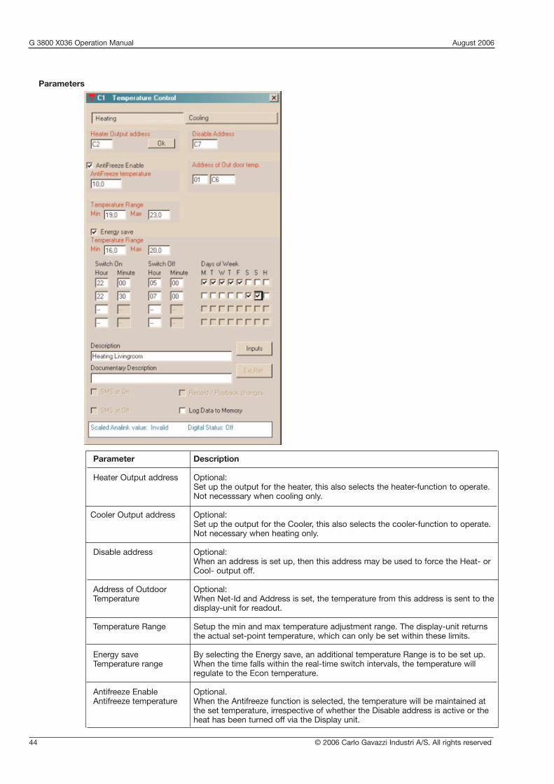
Parameter Description
Heater Output address Optional:Set up the output for the heater, this also selects the heater-function to operate.Not necesssary when cooling only.
Cooler Output address Optional:Set up the output for the Cooler, this also selects the cooler-function to operate.Not necessary when heating only.
Disable address Optional:When an address is set up, then this address may be used to force the Heat- orCool- output off.
Address of Outdoor Optional:Temperature When Net-Id and Address is set, the temperature from this address is sent to the
display-unit for readout.
Temperature Range Setup the min and max temperature adjustment range. The display-unit returnsthe actual set-point temperature, which can only be set within these limits.
Energy save By selecting the Energy save, an additional temperature Range is to be set up.Temperature range When the time falls within the real-time switch intervals, the temperature will
regulate to the Econ temperature.
Antifreeze Enable Optional.Antifreeze temperature When the Antifreeze function is selected, the temperature will be maintained at
the set temperature, irrespective of whether the Disable address is active or theheat has been turned off via the Display unit.
Parameters

© 2006 Carlo Gavazzi Industri A/S. All rights reserved 45
G 3800 X036 Operation Manual August 2006
2.3.6. Wireless Base
• Function: Setting up the Dupline wireless output modules
• DataLink Synk. Control signal for data-exchange between the Mastergenerator and the Wireless Base unit
Description:The Wireless Base is the joint-module, between the normal Dupline network and theDupline Wireless modules. The set up of the wireless base is needed when using wireless output modules. This channel object feeds information of which outputs the Wireless Base has to keep updated.
Select addresses for thewireless output modules
Parameters

G 3800 X036 Operation Manual August 2006
46 © 2006 Carlo Gavazzi Industri A/S. All rights reserved

© 2006 Carlo Gavazzi Industri A/S. All rights reserved 47
G 3800 X036 Operation Manual August 2006
This chapter will assist you in using the four different Dupline alarm systems:1. ISA-alarm (chapter 2.4.3)
This general alarm system developed acc. to ISA specifications is very flexible and has formed the basis of the development of the other alarms systems. Application areas include temperature- and level controlas well as plants requiring ordinary alarm functions.
2. Smoke alarm (chapter 2.4.4.)The primary purpose of this alarm system is the connection of the Dupline smoke detector. Of course, other smoke detectors can also be used if they provide a Normally closed or Normally opencontact. In this case, the connection to the Dupline system can take place through a digital input.
3. Intruder alarm (chapter 2.4.5)This system provides objects which allow monitoring of input signals for the intruder alarm. The inputscan be either floating or non-floating contacts connected to the system through digital Dupline inputs.
4. Water alarm (chapter 2.4.6)The Water alarm was developed as a separate system intended for the connection of water stop sensors.
The alarm systems differ in the following ways:
In the armouring (manual/door lock)In the type of alarm resetting (Acknowledgement/Reset)In the way of alarming andIn the time characteristics
The individual systems are described in detail in the following chapters. The object “Common siren” can beused in all system to allow a centralized alarm.
2.4.2.1. In-/output on one channelThe alarm systems benefit more than any objects fromt he capability of Dupline to differ between in- and out-puts on the same adress. Thereby it is possible to use a Normally open contact to reset the system and sub-sequently switch it in and out alternately.
The user should therefore not be surprised when:
a channel is activated without an input being activated ora channel is not activated although an input is activated
2.4.2.2. Master functionsAlarm objects can generally not be affected by master functions.
2.4.2. General features
2.4. Alarm functions
2.4.1. Overview

G 3800 X036 Operation Manual August 2006
48 © 2006 Carlo Gavazzi Industri A/S. All rights reserved
2.4.3. ISA Alarm• Function: General alarm system with inclusion of Passive detector, Active detector,
Acknowledgement, Reset, Lamp test and Alarm siren• Application: Monitoring of contacts and other alarm sources. • Select with mouse (“ISA alarm”) or short-cut key “A”
DescriptionThe purpose of the ISA-Alarm is to serve as a general alarm system acc. to the ISA specifications. The systemsupports two operation modes:
1. Standard: An alarm is reset (“Reset”) and switched on again manually by push-button.2. Auto reset: An alarm is reset and switched on again automatically after acknowledgement and removal of
the cause of alarm (Normal position of the alarm contacts).
Alarm contacts are generally included in the system through the objects “Passive detector” and “Active detec-tor”. The alarm system is switched on for the first time after downloading of the application when all alarm con-tacts are in off-position or the Reset button is activated. The alarm is released when one or several alarm con-tacts are activated. The system actuates the activated alarm contact approx. every second and switches thealarm output on for the set duration.
When the Acknowledgement button has been actuated in the “Standard” operation mode, the alarm contactsswitch from flashing to continuous operation and the alarm output is switched off. At this point of time, renewedactuation of an alarm contact does not trigger off an alarm. Subsequent actuation of the Reset button switches the alarm contact off and releases the alarm system.
If the Reset button is actuated before the Acknowledgement button, the system will also switch off the alarmoutput, but the alarm contacts will continue to flash. A new alarm is caused by renewed activation of an alarmcontact.
In the operation mode “Auto reset”, the alarm system is restarted after acknowledgement and with alarm contacts in off-position.
The status of the alarm contacts can easily be displayed, eg on a panel. This only requires that the output channels are coded for the same addresses as the alarm contacts. The functionality of the lamps can then betested by means of the object “Lamp test”.
For giving out alarms, the object “Common siren” can also be used. Further details can be found in chapter2.4.7.
The various ISA objects are selected under “Function”:
Passive detector: Normally open input. This object makes it possible to include passive detectors. When the contact is activated and a “1”-Signal consequentlytransmitted on the Dupline bus, an alarm is started.
Active detector: Normally closed input. This object makes it possible to include active detectors. When the contact is activated and a “0”-Signal consequently transmitted on the Dupline bus, an alarm is started.
Acknowledgement: This object makes it possible to include acknowledgement buttons. Upon actuation of an acknowledgement button, the alarm output is reset and the alarm source indication prepared for the resetting (changing from flashing to continuous operation).
Note: This object must always be configured.
Reset: This object is only needed in the operation mode “Standard” and makes it possible to include a button for resetting the alarm and restarting the system.This requires prior acknowledgement of the alarm.

© 2006 Carlo Gavazzi Industri A/S. All rights reserved 49
G 3800 X036 Operation Manual August 2006
If a contact is activated during resetting, the system triggers off a new alarm When this object is configured, the operation mode “Standard” is automaticallyselected.
Lamp test: This object makes it possible to test the function of lamps indicating the status ofthe alarm contacts. All alarm channels are activated upon actuation of the lamptest button.
Alarm siren: The alarm siren indicates the occurence of an alarm. The channel configured for this object can be used for alarm output on a random number of output modules. It usually activates a relay output switching a siren.
Parameters:
Parameter Description
Operation mode Standard:This setting means that activation of the alarm system takes place upon priorrelease by the reset button. This entails that the object “Reset” must be configured.Auto reset:With this setting, the system activates itself automatically upon acknowledge-ment, when all passive and active detectors are in their “normal” position (inwhich they do not trigger off alarms)
Note: Operation mode can be selected for any object of the ISA alarm - butapplies to the entire system. If the object “Reset” is selected to include a resetbutton, the system assumes that the operation mode “Standard” is to be selected. Simultaneously, the option operation mode is deactivated and can onlybe re-activated by unclicking the object “Reset”.If “Auto reset” is selected, the system prevents configuration of the “Reset”object.
Passive detector
Disable address Enter an address or a flag whose activation (“1”-signal) will leave out the Passivedetector function of the monitoring system whereby it cannot trigger off anyfurther alarms.
On-delay Enter a time value in seconds (0..255) must persist in order to activate the alarm.
Active detector
Disable address Enter an address or a flag whose activation (“1”-signal) will leave out the Passivedetector function of the monitoring system whereby it cannot trigger off any further alarms.

G 3800 X036 Operation Manual August 2006
50 © 2006 Carlo Gavazzi Industri A/S. All rights reserved
On-delay Enter a time value in seconds (0..255) for which the alarm signal must persist inorder to activate the alarm.
Acknowledge No configuration possibilities.
Reset No configuration possibilities.
Lamp test No configuration possibilities.
Alarm siren
Siren time This setting determines for how long the alarm output is to remain activated incase of alarm. The value can be between 0 and 60 min.
Note: With the Minus-key (-), the time can be set to an indefinite time. This is indicated by “»»»“.
Time characteristics
Operation mode “Standard”
Passive detector (IN)
Passive detector (OUT)
Acknowledgement
Reset
Alarm siren
T0n

© 2006 Carlo Gavazzi Industri A/S. All rights reserved 51
G 3800 X036 Operation Manual August 2006
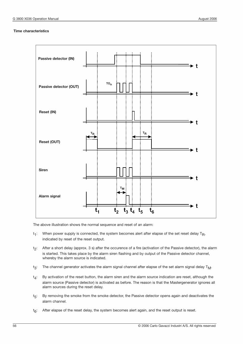
The above illustration shows the normal sequence and reset of an alarm in the operation mode “Standard”:
t1: When all contacts are in off-position, the Mastergenerator alerts the alarm system automatically upon
loading of the application.
t2: After elapse of on delay Ton, the Mastergenerator activates the alarm siren and causes the output of the
source channel to flash.
t3: By activation of the acknowledgement button, the Mastergenerator switches the alarm siren off
(provided that the siren time has not elapsed) and transfers the alarm source indication into a continuous signal.
t4: By activation of the reset button, the alarm source indication turns off and the system is alert again.
Operation mode “Auto reset”
The above illustration shows the normal sequence and reset of an alarm in the operation mode “Auto reset”:
t1: When all contacts are in off-position, the Mastergenerator alerts the alarm system automatically upon
loading of the application.If a contact is subsequently activated, initially nothing will happen because of entered on delay Ton.
t2: After elapse of on delay Ton, the Mastergenerator activates the alarm siren and causes the output of the
source channel to flash.
t3: After elapse of the siren time TA and reset of the alarm contact, the Mastergenerator switches the alarm
siren off.
t4: Acknowledgement deactivates the Normally open output, and the system at once brings itself in the alert
state again.
t5/t6: As t1/t2.
t7: In spite of the acknowledgement of the alarm, the flashing source indication changes to continuous
operation, because the alarm source is still activated at this point of time. Since the siren time has not yet elapsed, the alarm siren turns off.
t8: Only when the alarm source switches off, is the source indication also reset and the alarm system in the
alert state again.
Passive detector (IN)
Passive detector (OUT)
Acknowledgement
Alarm siren
Ta
TOn

G 3800 X036 Operation Manual August 2006
52 © 2006 Carlo Gavazzi Industri A/S. All rights reserved
Object Function Channel
In-/outputs
Alarm switch Alarm contact A1..A8
Push-button input Acknowledgement B1
Push-button input Reset B2
Push-button input Lamp test B3
Semiconductor output LED for source indi- A1..A8cation on a panel
Relay output Alarm siren B4
Configuration
ISA alarm: Alarm sources A1.. A8Passive detector
ISA alarm: Alarm B1Acknowledgement acknowledgement
ISA alarm: Reset Alarm reset B2
ISA alarm: Lamp test Activation of all B3LEDs on the panel
ISA alarm: Alarm siren Alarm sounding B4
Application Example
Task: In a chemical factory, eight laboratories are to be provided with alarm switches. Upon activationof an alarm button, the fire staff of the factory is informed via a siren. When the fire staff hasacknowledged the alarm, they go to the lab where the alarm was started.
Solution: The alarm switches are coded for channels A1 to A8. The source of the alarm is indicated on apanel whose LED is activated via a mimic display. The addresses correspond to those of thealarm contacts. The fire staff uses a button coded for address B1 to acknowledge the alarms.The alarm is reset through a reset button coded for address B2. The alarm is sounded bymeans of a horn activated through a relay output module coded for address B4.

© 2006 Carlo Gavazzi Industri A/S. All rights reserved 53
G 3800 X036 Operation Manual August 2006
DescriptionThe purpose of the Smoke Alarm is an alarm system consisting of smoke and fire indicators integrated asPassive or Active detectors. The wiring makes it possible to replace conventional fire alarm systems.
Smoke detectors are generally included in the system through the objects “Passive detector” or “Active detec-tor”. The alarm system is automatically alert after elapse of the Reset delay (set with the Reset object), whenthe Configuration software has been downloaded or the Mastergenerator has been switched on. The Reset out-put switches on within this time.
An alarm is triggered off when one or several alarm contacts are activated for more than 10 s. The channel forthe activated alarm contacts (alarm source indication) as well as the alarm output start to flash approx. everysecond. By subsequent activation of the reset key, the Mastergenerator switches the channel out of the system. If contacts are still activated, another alarm is triggered off after elapse of the reset delay.
Note: Configuration of the object “Reset” is absolutely necessary to ensure correct function.
The status of the alarm contacts can be shown in a simple way on a panel. All that is needed for this purposeis that the output channels are coded to the addresses of the alarm contacts.
The “Silent Alarm Signal” is intended for sending an alarm to a monitoring centre, but also suitable for SMSmessages.
For alarm purposes, the object Common Siren can also be used. Details can be found in the section describing The alarm siren/Common siren.
The various smoke alarm objects are set under “Channel function”:
Passive detector: Normally open input. This object makes it possible to includepassive detectors. When the contact is activated and a “1”-Signalconsequently transmitted on the Dupline bus, an alarm is started.
Active detector: Normally closed input. This object makes it possible to includeactive detectors. When the contact is activated and a “0”-Signalconsequently transmitted on the Dupline bus, an alarm is started.
Reset: This object makes it possible to include a button to reset the alarm and restart the system.If a contact is activated during reset, a new alarm is started after elapse of thereset delay.
Note: This object must be configured in order to achieve correct function ofthe smoke alarm system.
Alarm siren: The siren indicates that an alarm has occurred. The channel configured withthis object can be used to output the alarm on any output modules. It usually activates a relay output through which a siren is switched.
Note: The alarm output basically flashes.
Silent Alarm signal: When an alarm occurs, a channel configured with this object is activated for10 s and can thus be used to activate a telephone or GSM-modem.
2.4.4. Smoke Alarm
• Function: Fire alarm system including Passive detector, Active detector, Reset, Alarm Siren and Alarm signal
• Application: Wiring of smoke/fire indicators to an alarm system • Select with mouse (“Smoke alarm”) or short-cut key “S”

G 3800 X036 Operation Manual August 2006
54 © 2006 Carlo Gavazzi Industri A/S. All rights reserved
Parameters:
Parameter Description
Passive detector
Disable address Enter an address or a flag whose activation (“1”-signal) will leave out the Passivedetector function of the monitoring system whereby it cannot trigger off any furtheralarms.
Active detector
Disable address Enter an address or a flag whose activation (“1”-signal) will leave out the Activedetector function of the monitoring system whereby it cannot trigger off any further alarms.
Reset
Reset delay The delay after which the system becomes alert or an alarm is suppressed uponactivation of the reset button. This function can be used to ensure that the measuring chambers are completely emptied of smoke.
This time is also used in connection with download of the software and switchingon of the channel generator.

© 2006 Carlo Gavazzi Industri A/S. All rights reserved 55
G 3800 X036 Operation Manual August 2006
Parameter Description
Alarm siren
Siren time With this setting, you determine the duration of the activation of the alarm outputupon the occurence of an alarm. The value can lie between 0 and 60 min. Theentered value is automatically adopted by the Common Siren.
Alarm signal
Alarm signal delay With this setting, you determine the time to elapse after switching on of the alarmsiren till the alarm signal is activated. The value can lie between 0 and 10 min.
G 3800 X036 Operation Manual August 2006
56 © 2006 Carlo Gavazzi Industri A/S. All rights reserved
Time characteristics
Passive detector (IN)
Passive detector (OUT)
Reset (IN)
Alarm signal
TOn
Siren
Reset (OUT)
TRTR
TM
The above illustration shows the normal sequence and reset of an alarm:
t1: When power supply is connected, the system becomes alert after elapse of the set reset delay TR,
indicated by reset of the reset output.
t2: After a short delay (approx. 3 s) after the occurence of a fire (activation of the Passive detector), the alarm
is started. This takes place by the alarm siren flashing and by output of the Passive detector channel, whereby the alarm source is indicated.
t3: The channel generator activates the alarm signal channel after elapse of the set alarm signal delay TM.
t4: By activation of the reset button, the alarm siren and the alarm source indication are reset, although the
alarm source (Passive detector) is activated as before. The reason is that the Mastergenerator ignores all alarm sources during the reset delay.
t5: By removing the smoke from the smoke detector, the Passive detector opens again and deactivates the
alarm channel.
t6: After elapse of the reset delay, the system becomes alert again, and the reset output is reset.

© 2006 Carlo Gavazzi Industri A/S. All rights reserved 57
G 3800 X036 Operation Manual August 2006
Application Example
Task: In a residential building, eight rooms are to be equipped with smoke detectors. When an alarmoccurs, a siren switches on and the fire authorities are notified.
Solution: The alarm channels of the smoke detector are assigned to channels C1 to C8. The alarm sourceis indicated on a panel whose LED is activated by mimic display. The addresses correspond to those of the alarm contacts. The alarm is sounded through a horn which is activated through address D2 of a relay module. The alarm is reset again by a push-button onaddress B1.

G 3800 X036 Operation Manual August 2006
58 © 2006 Carlo Gavazzi Industri A/S. All rights reserved
2.4.5. Intruder Alarm• Function: Intruder alarm system including Passive/Active detector contacts, Toggle switch
functions, Motion detectors, Manual and Door-lock Armouring, Code lock Armouring, Alarm siren and Alarm signal
• Application: Wiring of intruder detector contacts to an alarm system• Select with mouse (“Intruder alarm”) or short-cut key “I”
DescriptionThe purpose of the Intruder Alarm is an alarm system consisting of various contacts integrated as Passive orActive detectors.
Apart from the contacts represented by their own objects (Passive and Active dectector), it is also possible toinclude toggle switch functions and motion detectors which have already been configured. This is done direct-ly when setting the parameters for these objects.
A system which is enabled will then start an alarm when one or several alarm contacts have been activated.The channel for the activated alarm channels (as alarm source indication) as well as the alarm output start toflash after the set time delay. By subsequent activation of the Manual armouring, the Door-lock armouring orCode lock armouring, the Mastergenerator switches the channel out of the system and switches the alarm out-put off.
If an alarm is not acknowledged before elapse of the alarm signal delay, the system automatically becomesalert again.
Note: For a minimum alarmsystem to operate correctly, according to Human behavior, the following objectsmust be included:
a) means to start/stop the alarm, either “Manual armouring”, “Door-lock armouring” or “Code lock armouring”
b) at least one alarm detector.c) the "Silent Alarm Signal"
Either the "Door Lock armouring" or "Code Lock Armouring" may be combined with the "Manual armouring".The Door/Code Lock has a priority over the Manual armouring. The Manual armouring allows alarm zones,whereas the Door/Code Lock always include ALL alarm detectors.
The status of the alarm detectors can be shown in a simple way on a panel. All that is needed for this purposeis that the output channels are coded to the addresses of the alarm contacts.
The object “Silent Alarm signal” is primarily intended for signalling an alarm-central, but equally important is,that when this signal has been passed, the alarm-system resets the detected alarms, and the surveillance cycleon the detectors is restarted.
The object Common Siren may be used as well.
The various Intruder alarm objects are selected under “Channel function”:
Passive detector: This object makes it possible to control windows, doors, etc. with Passive detector. If the contact is activated and a “1”-Signal consequently transmitted on the Dupline bus, an alarm is started.
Active detector: This object makes it possible to control windows, doors, etc. with Active detector. When the contact is activated and a “0”-Signal consequently transmitted on the Dupline bus, an alarm is started.
Manual The Manual armouring operates like a toggleswitch, and is used to start andarmouring: stop the Intruder alarm system.
The Manual armouring allows the alarm detectors to react upon their respective disable addresses, whereby more alarm zones can be created.

© 2006 Carlo Gavazzi Industri A/S. All rights reserved 59
G 3800 X036 Operation Manual August 2006
Door lock The Door Lock armoring operates like a push-button, and when armouring: activated the Intruder alarm system is started.
The Door Lock armouring must be kept active as long as the alarm system should be running.The Door Lock armouring prevents the alarm-detectors to react upon their respective disable addresses. The Door Lock armouring thus activates all alarm zones.
Code lock The Code Lock armouring operates like a toggle switch and is anarmouring: an alternative way to start and stop the Intruder alarm system.
The Code Lock armouring also prevents the alarm-detectors to react upon their respective disable addresses.Like the Door Lock, the Code Lock activates all alarm zones.
Note: Either Code Lock or Door Lock may be used at one time.
Alarm siren: The Alarm siren is used for the local audio alarmsignal. The Alarm sirene, also supports 'Visual' effects, as a selection of addresses may be set up to flash while the siren is on. This feature will further stress any intruder
Silent Alarm signal: The “Silent Alarm signal” is primarily intended for sending an alarm signal to a security centre. Equally important is, that when this signal has been sent, the Intruder alarm system resets the detected alarms, and the surveillance cycle on the detectors isrestarted.
Warning signal: This is an output for a local buzzer or lamp. When the alarm is armed, the Warning Signal will start pulsating slowly and increase pulse-speed until alarm is armed. For this function to operate properly, the armouring delay should be set to a minimum of 10 seconds.
Toggle switch Has an option for sending signals to Intruder alarm. See the chapter func-tion: describing the Toggle Switch function.
Motion detector: The motion detector can also be integrated in the intruder alarm. See the chapter describing the Motion detector.
Parameters
Parameter Description
Passive detector
Disable address Enter an address or a flag whose activation (“1”-signal) will prevent thedetector to cause an alarm. This feature may be used to have more alarmzones, when the alarm is armoured by the Manual Armouring.

G 3800 X036 Operation Manual August 2006
60 © 2006 Carlo Gavazzi Industri A/S. All rights reserved
Parameter Description
Active detector
Disable address Enter an address or a flag whose activation (“1”-signal) will prevent thedetector to cause an alarm. This feature may be used to have more alarmzones, when the alarm is armoured by the Manual Armouring.
Manual armouringDoor-lock armouringCode lock armouring
Armouring delay Determines the delay, from start of the alarm, until the the alarm surveillance becomes active. The delay is used to cope with the situation where a detector is activated, while the alarm is switched on.
Eg. The Alarm switch for start and stop is located in the hall, and thefrontdoor is equipped with an alarmdetector. Time should be set longenough, that a person may start the alarm and leave through the door,without causing an alarm.
De-armouring delay Determines how many seconds may pass from an alarm has occureduntill the alarm siren is activated. The time is used to cope with the situation, where the rightfull owner actually causes an alarm, by entry.
Eg. The Alarm switch for start and stop is located in the hall, and thefrontdoor is equipped with an alarm detector.Time should be set long enough, that a person may open the door, walkacross the hall, and stop the alarm.
Alarm siren
Siren time Enter for how long time the alarm output is to remain activated when analarm occurs. It is limited from 0 and 60 min.
The entered value is automatically adopted by the Common siren.

© 2006 Carlo Gavazzi Industri A/S. All rights reserved 61
G 3800 X036 Operation Manual August 2006
Parameter Description
Flash when Alarm Select this to setup the 'Visual' alarm effects. This allows you to select whichchannels are to flash while the Siren is activated.
Only when selected, the "Flash interval" entry and the "Flash addresses" buttonare visible.
Flash Interval Here you can enter the switch on/off time span of the flashing alarm signals. Theoption “Flash when Alarm” must be switched on.The value can lie between 0 and 60 s. Please note that flash intervals below 2seconds may turn out inaccurately because of the cycle time. When the value 0is entered, flashing takes place at the fastest possible rate.
Flashing Channels Click on this button to open the address matrix to select the addresses whichare to flash upon an alarm.
Only shown when "Flash when alarm" is selected.
Alarm signal
Alarm signal delay With this setting you can determine the time which is to elapse from the alarmsiren is activated till the alarm signal is activated. The value can lie between 0and 10 min.
Enable Simulated Select this option to make an automatic Playback of the adresses selected for occupation when Record/Playback.Alarm is armed
Selection of Record/Playback
RecordingThe selection of Record/Playback is available on most of the objects.The recording only takes place when the Intruder-alarm is in active.When selected for Record / Playback, the object’s output status will be record-ed at every 3 minutes intervals. The recording operates like an endless ‘tape-loop’ running over one week. The recorded data are stored permanently once every 24 hours just before mid-night, to continuously renew the record-history.
Playback takes place, when the Intruder-alarm is started and the "EnableSimulated occupation" is selected. The recorded data are used to activate theobjects in the same sequence as recorded.
If no records have been made for a certain time period while playback, theobjects will keep their last set on/off status.
The Playback activation of the objects, is a set – reset operation sent to theobjects, which is similar to a normal Manual activation.
When turning off the intruder alarm, the last set status will still remain on theobjects.

G 3800 X036 Operation Manual August 2006
62 © 2006 Carlo Gavazzi Industri A/S. All rights reserved
Time characteristics
Passive detector (IN)
Passive detector (OUT)
Manual armouring (IN)
Alarm signal
Alarm siren
Manual armouring (OUT)
TFVFV
TAATAVAV
TMM
The above illustration shows the normal sequence of an alarm using manual armouring to start and stop thealarm:
t1: When the Mastergenerator is switched on, the alarm system becomes alert through activation (once) of the
Manual Armouring function.
t2: An alarm contact is activated, eg by the opening of a secured port. Since the armouring delay TFV in this
example has not yet elapsed, nothing happens at first.
t3: After elapse of the armouring delay TFV, the alarm is started, ie both the channel of the alarm contact and
that of the Manual Armouring start to flash.
t4: After elapse of the de-armouring delay TAV, the Mastergenerator activates the alarm siren.
t5: After elapse of the siren time TA, the alarm siren channel is deactivated. The flashing of the alarm contact
and the Manual Armouring output continues.
TEV

© 2006 Carlo Gavazzi Industri A/S. All rights reserved 63
G 3800 X036 Operation Manual August 2006
Application Example
Task: In a residential building, eight rooms are to be equipped with window and door contacts. All lightswitches as well as two motion detectors are to be included in the system. When an alarmoccurs, a siren switches on and the police is informed via a telephone modem. A panel showsthe source of the alarm. The system should moreover make it possible to disable the alarm con-tacts on each floor.
Solution: The alarm contacts are grouped room-wise (switched in series). Each room is assigned to a NOcontact within the range E1..E8. The source of the alarm is shown on a panel whose LED is acit-vated via a mimic display. The addresses correspond to those of the alarm contacts. The alarmis sounded through a horn, which is activated via a relay on address F3. The alarm can be turnedon and off by the Manual Armouring function on F1 in the input range or through the Code LockArmouring function at the entrance door. Disabling of floors is performed with two switches.
t6: After elapse of the alarm signal delay TM set at the object “Alarm signal”, the channel is briefly activated.
At the same time, the alarm contact is continuously switched off and the Manual Armouring output continu-ously switched on.
t7: Activation of the Manual Armouring will acknowledge the alarm, and the Manual Armouring output will be
reset.
t8: Activating the Manual Armouring once more will bring the system back into the alert state - after the armour-
ing delay TFV.

G 3800 X036 Operation Manual August 2006
64 © 2006 Carlo Gavazzi Industri A/S. All rights reserved
DescriptionThe purpose of the Water Alarm is an alarm system consisting of water sensors integrated as Passive or Activedetector. The wiring makes it possible to replace conventional water alarm systems.
Water detectors are generally included in the system through the objects “Passive detector” or “Active detec-tor”. The alarm system is automatically alert after elapse of the Reset delay (set with the reset object), whenthe Configuration software has been downloaded or the Mastergenerator has been switched on. The Resetoutput switches on within this time.
An alarm is triggered off when one or several alarm contacts are activated for more than 10 s. The system stepsthrough the activated alarm contacts (as alarm indication) as well as the alarm output approx. every second.The alarm siren flashes with a pulse-pause ratio of approx. 3 s/57 s. By subsequent activation of the reset key,the Mastergenerator resets the stepping through of the alarm contacts and the alarm output. If contacts arestill activated, another alarm is triggered off after elapse of the reset delay.
Note: Configuration of the object “Reset” is absolutely necessary to ensure the correct function.
The status of the alarm contacts can be shown in a simple way on a panel. All that is needed for this purposeis that the output channels are coded to the addresses of the alarm contacts.
The “Silent Alarm Signal” is intended for sending an alarm to a monitoring centre. Also suitable for sending anSMS.
For alarm purposes, the object Common Siren can also be used. Details can be found in the chapter describing the alarm siren/Common siren.
The various water alarm objects are selected under “Channel function”:
Passive detector: Normally open input. This object makes it possible to includepassive detectors. When the contact is activated and a “1”-Signalconsequently transmitted on the Dupline bus, an alarm is started.
Active detector: Normally closed input. This object makes it possible to includeactive detectors. When the contact is activated and a “0”-Signalconsequently transmitted on the Dupline bus, an alarm is started.
Reset: This object makes it possible to include a button to reset the alarm and restart the system. If a contact is activated during reset, a new alarm is started after elapse of theReset delay.
Note: This object must be configured in order to achieve correct function ofthe water alarm system.
Alarm siren: The alarm siren indicates the occurrence of an alarm. The channel configuredfor this object can be used for alarm output on any outputmodules. It usually activates a relay output switching a siren.
In case of alarm, this output flashes with an on-time of approx. 3 s and an off-time of approx. 57 s.
Silent Alarm signal: When an alarm occurs, a channel configured for this object is activated for 10 s and can thus be used to activate a telephone or GSM modem.
2.4.6. Water Alarm• Function: Water alarm system including Passive detector, Active detector, Reset, Siren and
Alarm signal• Application: Wiring of water indicators, eg the water stop sensor, to an alarm system • Select with mouse (“Water alarm”) or short-cut key “W”

© 2006 Carlo Gavazzi Industri A/S. All rights reserved 65
G 3800 X036 Operation Manual August 2006
Parameter Description
Passive detector
Disable address Enter an address or a flag whose activation (“1”-signal) will leave out the Passivedetector function of the monitoring system whereby it cannot trigger off any furtheralarms.
Active detector
Disable address Enter an address or a flag whose activation (“1”-signal) will leave out the Activedetector function of the monitoring system whereby it cannot trigger off any further alarms.
Reset
Reset delay The delay after which the system becomes alert or is to remain switched off uponactivation of the reset button. The reset delay can be from 2 and 10 min.
Parameters

G 3800 X036 Operation Manual August 2006
66 © 2006 Carlo Gavazzi Industri A/S. All rights reserved
Parameter Description
Alarm siren
Siren time With this setting, you determine the duration of the activation of the alarm outputupon the occurence of an alarm. The value can lie between 0 and 60 min. Theentered value is automatically adopted by the Common Siren.
Alarm signal
Alarm signal delay With this setting, you determine the time to elapse after switching on the alarmsiren till the alarm signal is activated. The value can lie between 0 and 10 min.

© 2006 Carlo Gavazzi Industri A/S. All rights reserved 67
G 3800 X036 Operation Manual August 2006
Time characteristics
Passive detector (IN)
Passive detector (OUT)
Reset (IN)
Alarm signal
TEV
Siren
t
t
t1
tP
Man
_T
Wate
r_1a
t4t3
t
t
t
t5t2
Reset (OUT)
TR TR
TM
3s 57s
The above illustration shows the normal sequence and reset of an alarm:
t1: When power supply is connected, the system becomes alert after elapse of the set reset delay TR,
indicated by reset of the reset output.
t2: An alarm contact is activated. This starts the switch on delay TEV, which can run for 3 - 11 s depending
on the number of channels.
t3: Upon elapse of the switch-on delay TEV, the Mastergenerator causes the output of the activated contact
as well as the alarm siren to flash. The alarm siren is then switched on for approx. 3 s and switched off for approx. 57 s.
t4: Upon elapse of the alarm signal delay TM, the alarm signal is briefly activated.
t5: Activation of the reset button starts the reset delay and the siren is switched off.

G 3800 X036 Operation Manual August 2006
68 © 2006 Carlo Gavazzi Industri A/S. All rights reserved
Application Example
Task: In a residential building, eight rooms are to be protected against water damage. When an alarmoccurs, a siren switches on and the house owner is informed by means of an SMS-message.The room in question should be recognizable on a panel.
Solution: The alarm channels of the water stop sensors are assigned to channels G1 to G8. The alarmsource is indicated on a panel, whose LED is activated by a mimic display. The addresses correspond to those of the alarm contacts. The alarm is sounded through a horn which is activated through address D2 of a relay module. The alarm is reset again by a push-button onaddress H1.

© 2006 Carlo Gavazzi Industri A/S. All rights reserved 69
G 3800 X036 Operation Manual August 2006
2.4.7. Common Siren• Function: Common output of ISA-, Smoke-, Intruder- and Water alarm• Application: Output of several alarms on one siren in addition to or in replacement of alarm
system specific sirens • Select with mouse (“Common Siren”)
Parameter Description
Common siren
Channel function Here you select one or several alarm systems whose alarm will also activate thissiren.
Siren time Here you enter the max. time for which this siren is to remain activated. Thevalue can lie between 0 min and 60 min. (The Intruder alarm and ISA alarm allows infinite times, entered by the - (minus)key.
DescriptionThe Common Siren offers the possibility of transmitting the alarms of all alarm systems on one channel. Thealarm of the siren output behaves in the same way as the individual alarm sirens. If several alarms are on, theyare indicated wtih the following priority: 1. Smoke alarm2. Intruder alarm3. Water alarm4. ISA alarm
The operation of the common siren is independent of whether a siren was configured in the individual alarmsystem.
Note: The signal time entered in the Common siren is automatically adopted by the individual sirens. This alsoapplies to reversed function.
If an alarm has been acknowledged or reset, the Mastergenerator also resets the signal of the common siren.
Parameters:
Application Example
Task: In a commercial building, different alarm systems (smoke, water, ISA and Intruder) are to activatethe siren mounted outside.
Solution: The alarm systems described in the previous examples are used. The relay for the outdoor sirenis configured for address I1. The siren time of each connected alarm is configured.

G 3800 X036 Operation Manual August 2006
70 © 2006 Carlo Gavazzi Industri A/S. All rights reserved
2.5. Roller blind control
2.5.1. Decentralized roller blind up-down function
• Function: Up-Down control of roller blind motors• Application: Control of motors for roller blinds, sun blinds and roof windows through
Dupline modules G 3430 4249.• Run time and Switch time individually adjustable• Tilted blinds for sun blinds and priority control for example for wind sensor.
DescriptionThe decentralized roller blind up-down control makes it possible to run Dupline roller blind control modules forroller blind and sun blind motors. By organizing the up- and down-channels, the Mastergenerator ensuresundisturbed operation by preventing both directions from being activated at the same time and ensuring thatthe delay time is observed. The up-channel generally overrides the down-channel, ie if both are activated at the same time, theMastergenerator will execute the up-command.
Address configurationThe roller blind control can only be configured for an uneven channel number. This means that the up-channelmust have an uneven address number assigned to it and the down-channel must have an even address number assigned to it. This reflects the address coding of the roller blind modules. Here the up-channel mustalso have an uneven output assigned to it, while the down-channel must have an even output channeladdressed to it.
Note: When, in spite of correct address configuration, the motor runs in the opposite direction, the corresponding connecting cables of the motor are reversed. In this case, correct connection must be ensured- the channels must under no circumstances be reversed.
OperationThe up- and down-buttons configured for the addresses of the roller blind control allow very simple operation:
• By pressing the direction key once, the motor runs to the end position or for the duration of the roll time.• By pressing the same direction key once more, the motor stops.• By pressing in the opposite direction, the motor stops shortly and runs in the opposite direction until it
reaches end position or for the duration of the roll time.
When the option “Tilted blinds” is selected, the following options are available:
• If the direction key is pressed for less than three seconds, the motor stops when the key is no longerpressed.
• If the direction key is pressed for more than three seconds, the motor runs to the end position or for theduration of the run time. Here it is also possible to stop the motor by pressing the key once more or let itrun in the opposite direction by pressing the other direction key.
The Tilted blinds function makes it possible to activate the sun blinds shortly, so that instead of causing up- ordown-movement it changes the position of the tilting blinds.
Automating the roller blind controlSurely, many methods of automatic operation of roller blinds exist. Not only wind- and rain sensors, but alsolight sensors and clock timers increase comfort through automatic functions.
Such functions should - if not configured as priority address - usually be made by means of Logic setup, whereprimarily edge triggering is to be used which prevents continuous signals and allows permanent operator control. Further details can be found in the chapter on Logic Setup.
Connection of several motorsSimultaneous activation of several motors can be achieved by:
1. connecting all motors to separate outputs and2. assigning the same address to all up-channels as well as all down-channels.
We strongly advise against connecting two or more motors in parallel to one output channel.
The flexible way of controlling several motors centrally or group-wise is to use the Roller blind master function. Further details are found in chapter 2.5.2.

© 2006 Carlo Gavazzi Industri A/S. All rights reserved 71
G 3800 X036 Operation Manual August 2006
Parameter Description
Roller blind control(Decentralized Up-Down)
Roll time Insert the times (seconds) for which the motor is to run in each direction. Thevalue must be within 0 and 255 s.The selected time interval should ensure that the roller blinds can reach the endpositions in both directions where an end position contact must switch themotor off. Intermediate values allows shadow, for example. But it should beensured that the roller blind is in one of the end positions before start.The entered roll time is overwritten by the roll time of the master.
Reverse delay Enter the delay time (milliseconds) before the roller blind changes direction. Thevalue should lie between 500 and 2000 ms.
Tilting blinds This option allows adjustment of tilting blinds. The function stops within the firstthree seconds after the key is released.
The tilting blinds option must be activated if you want to define for how long theroller blinds must run in the opposite direction after expiry of the roll time.
Address By activation of the entered channel address, the roller blind runs in the selecteddirection for the entered roll time. As long as the indicated priority channel isset, input signals on the roller blind channels are ignored.
Note: The priority channel also overrides the master control.
Priority A channel or flag can be entered by which the up- or down-direction of theroller blinds is given priority
Parameters

G 3800 X036 Operation Manual August 2006
72 © 2006 Carlo Gavazzi Industri A/S. All rights reserved
t
t PM
an
_T
Ro
llerU
pD
_1a
t2t1 t3 t4
t
t
t6t5 t7
Time characteristics
Up-button
Down-button
Up-channel
Down-channel
TV
TL
TV
TU
TV
The above illustration is based on a roller blind application with adjustment of tilting blinds (Reverse Up timeTV of 3 s).
t1: The button for the up-direction is activated. Since the impulse is shorter than the Reverse Up time TV (3 s), the motor stops when the button is released.
t2: The up-direction is activated again. Since the impulse this time is longer than the Reverse Up time TV, the
roller master control attempts to switch the channel on for the total roll time.
t3: An additional actuation in the same direction stops the motor.
t4: Now the button for the up-direction is activated again and the motor consequently started in the up-
direction.
t5: By activation of the button for the down-direction, the motor is stopped and the Reverse delay TU starts.
t6: After elapse of the Reverse delay TU, the motor rolls in the down-direction.
t7: After elapse of the roll time TL, the motor is stopped. In order to reach the end of the roll time, the
activation of the Down-button must last longer than the Reverse Up time TV.

© 2006 Carlo Gavazzi Industri A/S. All rights reserved 73
G 3800 X036 Operation Manual August 2006
Object Function Channel
In-/outputs
Push-button inputs Local activation A1..B4C1..D4
Push-button inputs Group-wise B5/6Master D5/6
D7/8
Binary inputs for Priority control E1/E2wind/rain sensors
Relay outputs Motors A1..B4
Configuration
Decentralized Roller blind/roof A1.. B4Roller Blind Up-Down window control C1..D4
Roller Blind Master Group-wise control B5/6ground floor
Roller Blind Master Group-wise control D5/61st floor
Roller Blind Master Master control D7/8
Push-button function Connection of E1/E2
With the logic setup below, the rain sensor activates all roller blinds in the Down-direction through the masterfunction. If the wind sensor channel is set, the command of the decentralized up-down control is not executed(priority control at each decentral roller blind object).
Output Input 1 Function Input 2
D8 /E2 AND /E2
Application Example
Task: Control of several roller blinds as well as a roof window in a building. The system should includegroupwise control for two different floors as well as master control of all roller blinds together.To protect the roller blinds, a wind sensor and a rain sensor are installed. The roller blinds are toroll down by rain and up by wind, and wind has priority. The roof window is to close by rain.
Solution: The roller blinds as well as the roof window are activated through Dupline roller blind controlmodules. For the group-wise and the master control, roller blind master controls are used. Theaddress of the wind sensor is marked directly in the roller blind controls as priority address. Thedown-channel of the master control is activated through logic setup via the address of the rainsensor. Further details can be found in chapter 2.5.2.

G 3800 X036 Operation Manual August 2006
74 © 2006 Carlo Gavazzi Industri A/S. All rights reserved
2.5.2. Roller blind master
• Function: Group-wise or master control of decentralized roller blinds• Application: Group-wise or master control of motors for roller blinds, • Roll time with priority over individual roll times adjustable• Simultaneous or sequential roller blind start selectable• Reverse Up time for tilting blinds when end position reached.• Enter with mouse (“Roller blind master”)
DescriptionThis object enables group-wise and master control of for example roller blinds, sun blinds and roof windows.The decentralized roller blind channels configured above (chapter 2.5.1.) are included in the Roller blind master by marking them in the channel matrix.
The roll time set for the Roller blind master applies to all indiviual controls and overrides their roll times. Entering a Reverse Up Time allows automatic adjustment of tilting blinds at the end of a cycle. After elapse ofthe set roll time, the Mastergenerator switches the motor in the opposite direction for the set Reverse Up time.
The Roller blind master offers two operation modes for starting the motors:1. Simultaneous: All motors are started simultaneously.2. Sequential: All motors - starting with the lowest address - are started at 1 sec. intervals. Thereby current
peaks are avoided.
Address configurationThe Roller blind master can only be configured for an uneven address number. This means that the Up-channel must lie on an uneven (eg A1, B5 or P7) and the Down-channel must lie on an even address (eg A2,B6 or P8).
OperationThe Up- and Down-buttons configured for the addresses of the Roller blind master allows very simple operation:• By pressing a direction key once, all selected motors roll until end position is reached or the roll time has
elapsed.
• By pressing the same direction key once more, the set roll time starts again. Thus, it cannot be stopped.
• By pressing the other direction key, the motors stop shortly (decentrally set Reverse Up time) and run inthe opposite direction until the end position is reached or the set roll time has elapsed.
• After elapse of the Down-time, the motors run in the Up-direction, provided that a Reverse Up time hasbeen entered and the Tilting blinds function has been activated at the decentral roller blind control.
• During the master command, all motors can also be actuated through their individual decentral roller blindcontrol channels. All functions of the decentral roller blind control are available (Stop, reversal of direction,adjustment of tilting blinds).
Automation of master commandSurely, many methods of automatic operation of roller blinds exist. Not only wind- and rain sensors, but alsolight sensors and clock timers increase comfort through automatic functions.
Such functions should - if not configured as priority address - usually be made by means of Logic setup, whereprimarily edge triggering is to be used which prevents continuous signals and allows permanent control by theoperator. Further details can be found in the chapter describing the logic setup.
Hint: Please be aware that in the application of clock timers in particular, only one master command can beexecuted at a time. When several master commands are activated at the same time, the Mastergenerator onlyexecutes the command with the highest address number, eg H3/H4 before F7/F8.

© 2006 Carlo Gavazzi Industri A/S. All rights reserved 75
G 3800 X036 Operation Manual August 2006
Parameter Description
Roller blind master
Operation mode The setting determines whether the roller blinds are started simultaneously orsequentially. With the setting “Sequentially”, the roller blinds start and stop successively at 1 second intervals. This time interval is also observed in con-nection with change of direction or tilting blind (Reverse Up time). This timeinterval does not affect the set roll time.
Roll time The roll time determines for how long the roller blinds must run. This roll timeoverrides the roll time set in the Decentral up-down roller blind control.
Reverse Up time The Reverse Up time determines the time in seconds for which the roller blindsmust run in the opposite direction after expiry of the roll time. Applies to tiltingblinds.
Note: The Controller only executes the Reversing function in decentral rollerblind controls in which the option adjustment of “Tilting blinds” has been acti-vated.
Parameters

G 3800 X036 Operation Manual August 2006
76 © 2006 Carlo Gavazzi Industri A/S. All rights reserved
t
t PM
an
_T
Ro
llerM
aste
r_1a
t2t1 t3 t4
t
t
t6t5 t7
t
t
Time characteristics
Up-button central
Down-button central
Up-channel (roller blind 1)
Down-channel (roller blind 1)
Up-channel (roller blind 2)
TRTL
TV TU
TU TU
TV TV TL
The above illustration is based on a roller blind master application with sequential operation mode and aReverse Up time TR.
t1: The button for the up-direction is activated. The up-channel of the first motor is activated.
t2: In the operation mode “Sequential”, the Mastergenerator switches the up-channel of the second motor
on after a time delay of 1 s.
t3: Before elapse fo the master roll time, the Down-button is actuated whereby the roller blind is forced in
the opposite direction. The motors stop one by one, and the Reverse delay TU set for the decentral roller
blind object begins.
t4: After elapse of the Reverse delay TU, the first motor starts in the opposite direction, while the second
motor is activated after a delay of 1 s.
t5: After the end of the roll time TL, the Reverse delay TU is postponed due to the subsequent Reversing.
t6: Based on the set Reverse Up time TR, the roller blinds again run in the opposite direction in order to tilt
the blinds.
t7: After elapse of the Reverse Up time TR, the motor of the first roller blind stops
Application exampleA detailed example is described in connection with the decentralized up-down roller blind function.
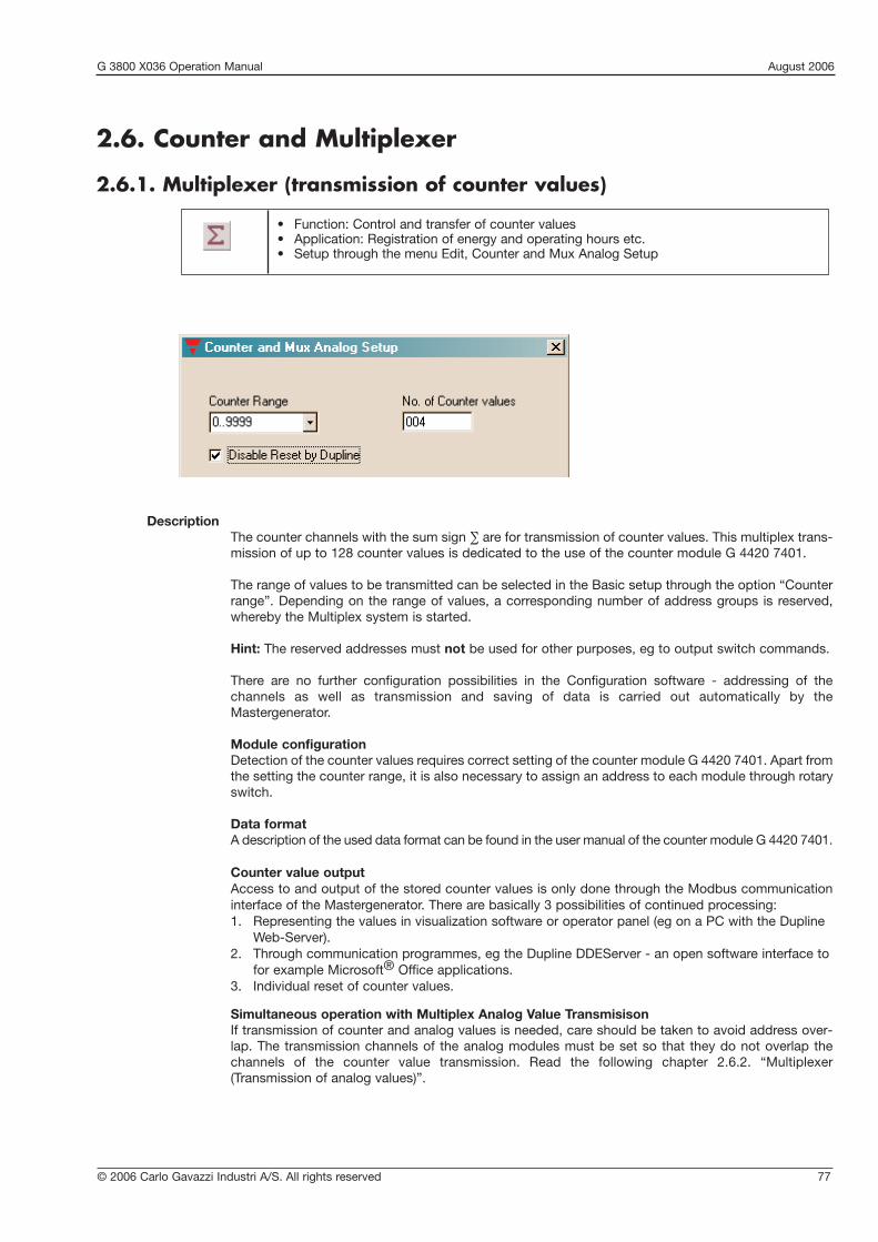
© 2006 Carlo Gavazzi Industri A/S. All rights reserved 77
G 3800 X036 Operation Manual August 2006
2.6. Counter and Multiplexer
2.6.1. Multiplexer (transmission of counter values)
• Function: Control and transfer of counter values• Application: Registration of energy and operating hours etc.• Setup through the menu Edit, Counter and Mux Analog Setup
DescriptionThe counter channels with the sum sign ∑ are for transmission of counter values. This multiplex trans-mission of up to 128 counter values is dedicated to the use of the counter module G 4420 7401.
The range of values to be transmitted can be selected in the Basic setup through the option “Counterrange”. Depending on the range of values, a corresponding number of address groups is reserved,whereby the Multiplex system is started.
Hint: The reserved addresses must not be used for other purposes, eg to output switch commands.
There are no further configuration possibilities in the Configuration software - addressing of the channels as well as transmission and saving of data is carried out automatically by theMastergenerator.
Module configurationDetection of the counter values requires correct setting of the counter module G 4420 7401. Apart fromthe setting the counter range, it is also necessary to assign an address to each module through rotaryswitch.
Data formatA description of the used data format can be found in the user manual of the counter module G 4420 7401.
Counter value outputAccess to and output of the stored counter values is only done through the Modbus communicationinterface of the Mastergenerator. There are basically 3 possibilities of continued processing:1. Representing the values in visualization software or operator panel (eg on a PC with the Dupline
Web-Server).2. Through communication programmes, eg the Dupline DDEServer - an open software interface to
for example Microsoft® Office applications.3. Individual reset of counter values.
Simultaneous operation with Multiplex Analog Value TransmisisonIf transmission of counter and analog values is needed, care should be taken to avoid address over-lap. The transmission channels of the analog modules must be set so that they do not overlap thechannels of the counter value transmission. Read the following chapter 2.6.2. “Multiplexer(Transmission of analog values)”.

G 3800 X036 Operation Manual August 2006
78 © 2006 Carlo Gavazzi Industri A/S. All rights reserved
Parameter Description
(Detection of counter values)
Counter range With this setting made under <Edit><Counter And Mux Analog Setup>, youselect the range of counter values. Depending on the range, a correspondingnumber of channel groups, beginning by “B” are reserved:
Counter ranges Reserved groups
--- None (counter operation switched off)
0..99 B..C
0..9999 B..D
0..999999 B..E
0..99999999 B..F
No. of Counter values Defines how many Counter values are to be transmitted on the Dupline net-work.The default value is set to 128 counter values, however the real no of values should be entered, to generally increase the update-time.
Disable Reset by Dupline Select this option, to prevent accidential reset of the countermodules.Address B1, may be used for resetting ALL modules.
Parameters
Object Function Channel
In-/outputs
Counter input Detection of B1..F8impulses from energy counter
Relay output Switching power G1..N8outlets
Configuration
Counter range Channels for B1..F8counter values
Toggle switch function Switches for power G1..N8
Application Example
Task: On a camping site, 64 current values are to be detected and used on a PC for the issue of invoices.
Solution: The counter modules G4420 7401 are built into the local power cabinets. Four Dupline energyEnergy Kwh meters supply one G4420 7401 with the corresponding count-pulses. The Mastergenerator is configured to 8 digits, occupying addresses from B1 to F8.
Through the DDE server software, an application is built in a spread-sheet software, where theindividual counters may be reset, when new guests arrive.
The voltage of the individual power outlet is turned on from the PC through a relay module. Freechannels are used for this purpose.
The applied Mastergenerator can, of course, also perform additional automation functions.

© 2006 Carlo Gavazzi Industri A/S. All rights reserved 79
G 3800 X036 Operation Manual August 2006
• Function: Object for detection of max. 112 analog values• Application: Fast transmission of multiplexed analog values through Dupline analog modules• Configuration under the option “Multiplexer channels” in the Basic setup
Signal available means that an input module continuously provides the valueValue valid indicates that the value is validAn “0” stands for a positive valueAn “1” stands for a negative value
Channel C1 C2 C3 C4 C5 C6 C7 C8 D1 D2 D3 D4 D5 D6 D7 D8Factor 1 8 4 2 1 8 4 2 1 8 4 2 1Example:Channel state: 1 1 0 1 1 0 0 1 0 1 0 1 0 1 1 1Value 1 9 5 7
Sig
nal a
vaila
be
Valu
e va
lid
Sig
n
Valu
e in
tho
usan
ds
Time Value in hundreds Value in tens Single-digit value
2.6.2. Multiplexer (transmission of analog values)
DescriptionThe (original) multiplexing of analog values makes it possible to read and write Dupline multiplex analog values. As opposed to AnaLink transmission with analog sensors, two addresses are needed instead of one,which allows transmission of accurate analog values. The transmission speed is also higher. A full analog value needs one bus cycle, at best. AnaLink values need 256 cycles.
While for the transmission of counter values (see chapter 2.6.1.) only input modules are available, variousDupline output modules are available for multiplex analog values. The output modules have the output ranges0..20 mA, 4..20 mA and 0..10 V.
In connection with the configuration of the multiplexer in the Basic setup (Options Multiplexer Count and Multiplexer delay), the Configuration software automatically reserves four channels (A1..A4) for addressing themodules. The addressing on these channels is performed automatically by the Mastergenerator. Data is transferred on two consecutive address groups (C/D, E/F, G/H, I/J, D/L, M/N and O/P). The channels can beset individially to the applied modules and can thus not be reserved by the Mastergenerator.
Also when the number is limited to 16 because only four channels have been reserved, 112 values can actually be processed. This is possible because up to 7 analog channels receive the same binary address, butsubsequently transmit the values to different channel groups. (see above).
Note: The reserved addresses must not be used for other purposes, eg to output switch commands.
Module configurationTransmission of analog values requires correct setting of the analog modules. Apart from the setting of thetransmission channels, it is also necessary to assign a binary address to each module. Details can be found inthe datasheets.
Data formatWithin the two channel groups (in this case C and D), the value “1957” is generated continuously.

G 3800 X036 Operation Manual August 2006
80 © 2006 Carlo Gavazzi Industri A/S. All rights reserved
Parameter Description
Multiplexer(Transmisison of analog values)
Multiplex channels With this setting made under <Edit><Counter & Mux Analog Setup>, youselect how many modules should be addressed. The number depends on thenumber of applied modules and their in-/output channels. From 0 to 16addresses can be selected. The value 0 switches the multiplex operation out.
Multiplex delay With this setting made under <Edit><Counter & Mux Analog Setup>, youselect how fast the Mastergenerator may scan the multiplex addresses. Thissetting only has an effect when multiplex transmission has been activated (atleast 1 multiplex channel selected).Since some of the Dupline Multiplex modules need a large part of their capacityfor internal processing, their response time is reduced. This can be balancedby a longer delay. The Mastergenerator then waits for the corresponding number of cycles between the scans.
Parameters
Processing of analog valuesAs opposed to the counter values, it is not only possible to visualize the analog multiplex values through theModbus communication interface, but also to change them. There are basically two possibilities of value processing:1. Representing the values in visualization software or operator panel (eg on a PC with the Dupline
Web Server).2. Through communication programmes, eg the Dupline DDEServer - an open software interface to for
example Microsoft® Office applications.
Simultaneous operation with transmission of multiplex analog valuesIf both multiplex modes are used, care should be taken to avoid address overlap. The transmission channelsof the analog modules must be set so that they do not overlap the channels of the counter value transmission. Read the preceding chapter 2.6.1. “Multiplexer (Transmission of counter values)”.
Working with test unit GTU8GTU8 makes it easy to read out and simulate analog values of this format (operation mode Analog BCD). Inthe case of simulation, care should be taken that both the bit “Signal available” and the validity bit have beenset (see above).
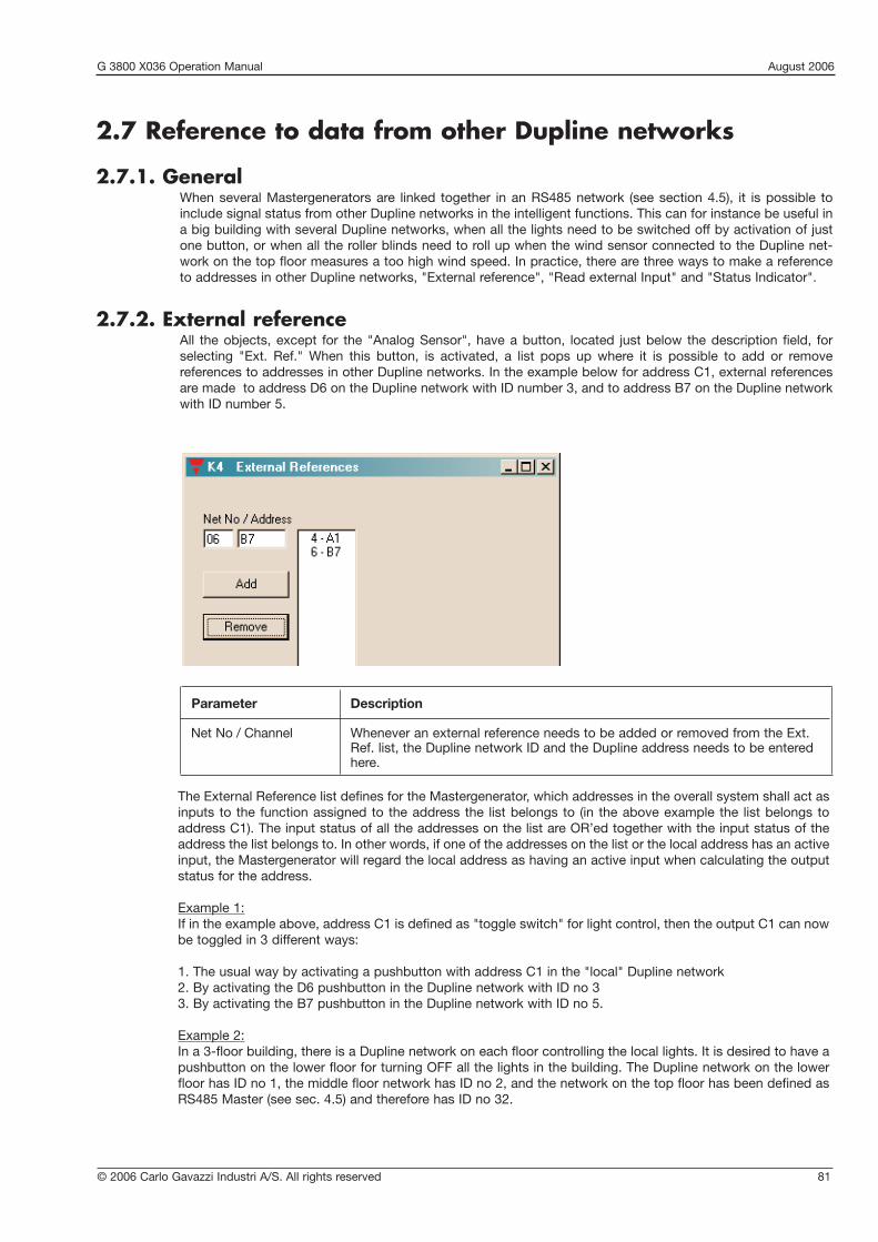
© 2006 Carlo Gavazzi Industri A/S. All rights reserved 81
G 3800 X036 Operation Manual August 2006
The External Reference list defines for the Mastergenerator, which addresses in the overall system shall act asinputs to the function assigned to the address the list belongs to (in the above example the list belongs toaddress C1). The input status of all the addresses on the list are OR’ed together with the input status of theaddress the list belongs to. In other words, if one of the addresses on the list or the local address has an activeinput, the Mastergenerator will regard the local address as having an active input when calculating the outputstatus for the address.
Example 1:If in the example above, address C1 is defined as "toggle switch" for light control, then the output C1 can nowbe toggled in 3 different ways:
1. The usual way by activating a pushbutton with address C1 in the "local" Dupline network2. By activating the D6 pushbutton in the Dupline network with ID no 33. By activating the B7 pushbutton in the Dupline network with ID no 5.
Example 2:In a 3-floor building, there is a Dupline network on each floor controlling the local lights. It is desired to have apushbutton on the lower floor for turning OFF all the lights in the building. The Dupline network on the lowerfloor has ID no 1, the middle floor network has ID no 2, and the network on the top floor has been defined asRS485 Master (see sec. 4.5) and therefore has ID no 32.
Parameter Description
Net No / Channel Whenever an external reference needs to be added or removed from the Ext.Ref. list, the Dupline network ID and the Dupline address needs to be enteredhere.
2.7 Reference to data from other Dupline networks
2.7.1. GeneralWhen several Mastergenerators are linked together in an RS485 network (see section 4.5), it is possible toinclude signal status from other Dupline networks in the intelligent functions. This can for instance be useful ina big building with several Dupline networks, when all the lights need to be switched off by activation of justone button, or when all the roller blinds need to roll up when the wind sensor connected to the Dupline net-work on the top floor measures a too high wind speed. In practice, there are three ways to make a referenceto addresses in other Dupline networks, "External reference", "Read external Input" and "Status Indicator".
2.7.2. External referenceAll the objects, except for the "Analog Sensor", have a button, located just below the description field, forselecting "Ext. Ref." When this button, is activated, a list pops up where it is possible to add or remove references to addresses in other Dupline networks. In the example below for address C1, external referencesare made to address D6 on the Dupline network with ID number 3, and to address B7 on the Dupline networkwith ID number 5.

G 3800 X036 Operation Manual August 2006
82 © 2006 Carlo Gavazzi Industri A/S. All rights reserved
The all-OFF function can be implemented the following way:
1. In each of the 3 Mastergenerators, a master function is defined on address E2 for turning OFF all lights on the local Dupline network.
2. The all-OFF pushbutton on the lower floor is coded E2 and will therefore turn OFF all lights on the lower floor when activated, as desired.
3. In the Mastergenerator on the middle floor, an External Reference has to be defined for the local Master Function on address E2 in order to enable the all-OFF pushbutton on the lower floor to trigger it. The reference is therefore made to address E2 on the Dupline network with ID no 1.
4. In the Mastergenerator on the top floor, an External Reference has to be defined for the local Master function on address E2 in order to enable the all-OFF pushbutton on the lower floor to trigger it. The reference is therefore made to address E2 on the Dupline network with ID no 1.
5. Activating the E2 pushbutton on the lower floor will now activate not only the local all-OFFMaster Function on the lower floor, but also the all-OFF Master Functions on the middle andtop floors, and thereby the desired function is achieved.
In the above example, the master function is assigned to address E2 in each Dupline network, but obviously,it is not necessary to use the same address. The addresses can be completely different, if desired.
2.7.3. Read external inputThis function is only available for addresses used for Analink signals. The function makes it possible to usethe Analink value transmitted on one Dupline network in all the other Dupline networks. If for example the sig-nal from a wind speed sensor is transmitted on the top floor Dupline network, then the "Read External Input"function makes it possible for the Mastergenerators on the lower floors to use the wind speed value for con-trol of the local roller blinds.
Parameter Description
Read External Input If selected, the Mastergenerator reads the Analink value from an externaladdress.
Net No / Channel Defines the Dupline Network ID no and address from where the Analink valueshall be read.

© 2006 Carlo Gavazzi Industri A/S. All rights reserved 83
G 3800 X036 Operation Manual August 2006
When "Read External Input" is selected for an address configured as Analink, it becomes possible to enter theDupline ID no. and address from which the Analink shall be read and used as input. In the example above,address D2 has been defined as Analink wind sensor, but because "Read External Input" is selected, the windspeed value does not come from the local Dupline network, but from the Dupline network with ID no 02address F5. Other functions such as limit value monitoring with Control Output works exactly as if the Analinkvalue came from a local sensor. So even though the Mastergenerators in the RS485 link are using the sameinput value from the Dupline network with ID 2 address F5, they can operate with different wind speed limitsfor forcing roller blinds up.
2.7.4. Status IndicatorWhereas "Ext. Ref." and "Read External Input" are referring to inputs from other Dupline networks, the "Status Indicator" refers to an external output. This means that it is possible to assign the output of a Duplinechannel simply to be a copy of an address in another Dupline network. Only addresses defined as blank/indicator. Only addresses defined as blank/indicator channels can be used as Status Indicators (see sec.2.2.1). The Status Indicator function can eg be used in connection with alarm systems. Each Dupline has it ownalarm system, but by using the Status Indicator function it is possible in a Dupline network to read the status of an alarm signal in any other Dupline network.
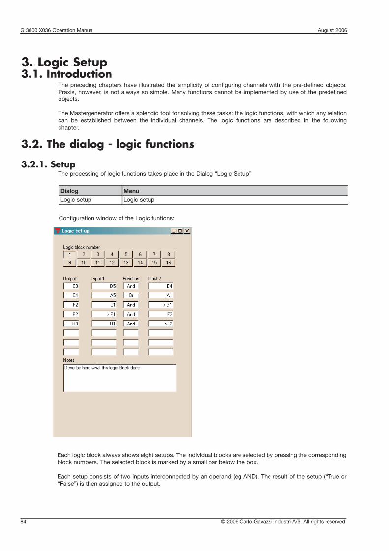
G 3800 X036 Operation Manual August 2006
84 © 2006 Carlo Gavazzi Industri A/S. All rights reserved
3. Logic Setup3.1. Introduction
The preceding chapters have illustrated the simplicity of configuring channels with the pre-defined objects.Praxis, however, is not always so simple. Many functions cannot be implemented by use of the predefinedobjects.
The Mastergenerator offers a splendid tool for solving these tasks: the logic functions, with which any relationcan be established between the individual channels. The logic functions are described in the following chapter.
3.2. The dialog - logic functions
3.2.1. SetupThe processing of logic functions takes place in the Dialog “Logic Setup”
Dialog Menu
Logic setup Logic setup
Configuration window of the Logic funtions:
Each logic block always shows eight setups. The individual blocks are selected by pressing the correspondingblock numbers. The selected block is marked by a small bar below the box.
Each setup consists of two inputs interconnected by an operand (eg AND). The result of the setup (“True or“False”) is then assigned to the output.
© 2006 Carlo Gavazzi Industri A/S. All rights reserved 85
G 3800 X036 Operation Manual August 2006
Designation Values Description Abb. 1)
Output A1..P8 Channel or flag whose status is to be changed AQ1..Z8
Input 1 A1..P8 Channel or flag causing the first part of the E1Q1..Z8 conditions for the change in output status-,/,\
Function AND, OR, XOR The logic operand connection the two inputs Fkt
Input 2 A1..P8 Channel or flag causing the second part of the E2Q1..Z8 conditions for the change in output status-,/,\
1) This abbreviation is used in the following to designate the various components.
3.3 Application
3.3.1. Setups and Functions
3.3.1.1. Creating SetupsNavigatingFor jumping between the individual fields, press the Tab-key (forward) or the Alt- and Tab-keys(backwards)
AddingAll fields in a logic setup must be filled in, ie all 4 components must be available. Any number ofsetups can be selected, and gaps are allowed.
To add a function, place the cursor in any field in the row. Depending on the component, press aletter or number key.
ChangingChanges are made in the same way as additions: place the cursor in the field “Function” and over-write the old value with the new value.
DeletingThe entire logic row can be deleted by placing the cursor in the field “Function” and press theDelete-key or the space bar.
3.3.1.2. Mode of operationThe in- and outputs can be channel addresses (A1 to P8) or flags (Q1 to Z8).Depending on the inputs or logic setup (result of the function), the output is set in each bus cycle(max. all 134 ms). This means that the output assumes the value “0” when the setup is not fulfilledand the value “1” when the setup is fulfilled.
The three logic functions correspond to the mathematical functions AND, OR and XOR (exclusiveof OR).
ANDThe output is always “1”, when both inputs are “1”.
ORThe output is always “1”, when one or both inputs are “1”.
XORThe output is “1”, when only one of the two inputs is “1”.

G 3800 X036 Operation Manual August 2006
86 © 2006 Carlo Gavazzi Industri A/S. All rights reserved
The following tables summarize the results of the logic setups:
ANDE1 E2 A0 0 01 0 00 1 01 1 1
ORE1 E2 A0 0 01 0 10 1 11 1 1
XORE1 E2 A0 0 01 0 10 1 11 1 0
Example: If in the XOR-function, both input 1 (E1) and input 2 (E2) have the value “1”, the output (A) will assumethe value “0”.
3.3.2. Inversion and Edge TriggeringA special feature of the logic functions is the possibility of inverting the output:• When a - (minus) is added in front of the value, the input value and consequently the output are inverted,
ie if the input had the value “0”, it gets the value “1” and vice versa.• Adding a / (slash) in front of the address leads to triggering on leading edge.• Adding a \ (backslash) in front of the address leads to triggering on trailing edge.
This change in ouput does not affect the input channels or flags.
3.3.2.1. InversionInversion can be applied to both channels and flags. The output can be of any type.
Example of a logic setup:
Output Input 1 Function Input 2
A1 E1 AND -E2
Time characteristics
t
t
t
E1
E2
A1
Output A is only active, when input E1 is active and input E2 is not active (range between the dotted lines). Theinternal processing in the Mastergenerator inverts the value of E2 before it is output (ie sees it as active).
3.3.2.2. Example of Edge TriggeringEdge triggering can only be used on channels A1 to P8. Since the process is dynamic and lasts only two buscycles, it is necessary to select an output channel capable of processing impulses, eg channels with toggleswitch function, timer function or master function.
A push-button function can also be generated with this setup, but it should be noted that in this case the out-put will only be active for one cycle.
Example of a logic setup:
Output Input 1 Function Input 2
A1 E1 AND /E2

© 2006 Carlo Gavazzi Industri A/S. All rights reserved 87
G 3800 X036 Operation Manual August 2006
3.3.3. Using the on-board I/OsThe Mastergenerator facilitates 8 on-board I/Os. The 4 Inputs and 4 Outputs are assigned to specific flags, sothey can be utilized via the logic functions.
Examples:If it is desired that on-board Output number 1 shall follow the status of channel B5,the following line can be entered: Q5 = B5 and B5
If it is desired that on-board Input number 3 shall be transmitted on Dupline addressC4, the following line can be entered: C4 = Q3 and Q3.
Please notice that Firmware version 2,0 and onward implies changes in the flag adresses for the 8 on-boardI/Os of the Mastergenerator.In this case the user must manually alter his flag adresses from X, Y to Q:
3.3.4. Internal processing of the logic setupsThe Mastergenerator processes the setups from the first expression in block 1 and onwards.
3.4. Notes and DocumentationFor later documentation of the logic setups, it is useful to add comments in the field “Notes”. When the logicsetups are later printed out, the notes appear next to the individual rows so that each individual function iscommented on.
3.4.1. Input definitionsThe input definitions are used to document the coding of input modules (transmitters). The documentation cre-ated is a list of assigned names referring to the input-modules and how their respective I/Os are to be addressed.
This information is stored in the Generator along with the configuration,and ensures that all documentation is available.
To create the list1) Enter a name for the input in the text entry field
2) Click on the Add button, to copy the name onto the list.
3) To assign I/O addresses to the input, mark the input on the list
4) Either click on the buttons I/O1 to I/O 8 to assign the current select-ed channel, as seen in the title-bar (A1), or enter the addresses directly in the I/O 1 ..I/O 8 fields.
To modify an item description in the list1) Mark the item in the list, and the item name will appear in the textentry field
2) Modify the name, and click Replace Name button.
To remove an item in the listMark the item and click on the Remove button.
I/O Flag
Input 1 Q1
Input 2 Q2
Input 3 Q3
Input 4 Q4
Output 1 Q5
Output 2 Q6
Output 3 Q7
Output 4 Q8
Inputs OutputsFirmware version < 2,0 Y1, Y2, Y3, Y4 X5, X6, X7, X8Firmware version = > 2,0 Q1, Q2, Q3, Q4 Q5, Q6, Q7, Q8
G 3800 X036 Operation Manual August 2006
88 © 2006 Carlo Gavazzi Industri A/S. All rights reserved
4. Communication Ports4.1. General
The Mastergenerator is equipped with 3 serial communication ports, which can be used for configuration,communication with external devices and for networking of Mastergenerators. The two RS232 ports, COM1and COM2, are accessible via two DB9 connectors in the front of the module, while the RS485 port is accessible through screw terminals. For pin-outs and technical details, please refer to the Mastergeneratordatasheet. All three ports can be used simultaneously.
4.2. ProtocolThe protocol used for all serial communication between the Mastergenerator and external devices is theModbus protocol. The format of this protocol can be found on the homepage www.modbus.org. By using thisprotocol, the following functions can be performed:
• Read the digital output status of Dupline addresses (status of receivers)• Read the digital input status of Dupline addresses (status of transmitters)• Read the values from AnaLink transmitters (analog)• Read the values from Counter Modules (type G44207401)• Read the values from Multiplexed Analog Transmitters• Read the pulse counts on Dupline addresses since last Reset command (note 1)• Write data to activate digital Dupline addresses (writing a "1" to an address creates the same result as
having an active transmitter on that address). • Write data to force Dupline addresses ON (writing a "1" to an address will force the receiver outputs with
this address ON, irrespective of the function assigned to that address)• Write data to be output as multiplexed analog values• Write data to change the set-points of Analink addresses (can eg be used to change the set-point of a
temperature control function)• Write data to change switching times on Dupline addresses configured for real-time control• Issue commands for Reset and Freeze of pulse counts on specific Dupline addresses (Note 1)
Note 1: A pulse counter that increments on OFF-to-ON transitions is automatically assigned to each Duplineaddress. The counting is performed on BCD format in the range 0..9999 (if the count exceeds 9999 it will roll-over to 0). A "freeze" command must be issued prior to reading a pulse count from a Dupline address. The"frozen" value can then be read while the counting continues in the background. Issuing a reset command foran address resets the counter for that address.
A Modbus memory map defining which Modbus memory locations are used for the different types of data canbe found in Appendix C of this manual.The signal status of a given Dupline address can be read in any location related to that address in the Modbusmemory map, but obviously, meaningful data is only achieved from the memory location reflecting the actualuse of that address. If eg an AnaLink temperature sensor is connected to channel B5, it does not make senseto read the digital status of address B5, but it is possible.
In order to provide easy access to Dupline data from a PC, Carlo Gavazzi offer the Dupline data access package (DUPDATACC), consisting of a DDE-driver and an ActiveX-server. The DDE-driver offers the possibility to copy and paste Dupline data directly into EXCEL spreadsheets and other Windows applications,while the ActiveX driver makes it easy for Visual Basic, C++ and Delphi programmers to access Dupline data.
4.3. COM1The RS232-port COM1 is typically used for download/upload of Mastergenerator configuration files, becauseit has a fixed baud-rate of 115 kBaud just like the configuration software. But it can also be used for communication with external devices such as PC’s, PLC’s and Touch Screens.
4.4. COM2The RS232-port COM2 can be used for Dupline-Online operation. When Logged Dupline data is to be transmitted via Internet to the central Dupline-Online server, COM2 is used to send the Log Records to theexternal RS232-to-Ethernet converter ETHCONV1, which then takes care of the Internet transmission. COM2has an adjustable baudrate in the range 2400 .. 115200 (note: for Dupline-Online operation the baudrate mustbe set to 9600). COM2 can also be used for communication with external devices such as PC’s, PLC’s and

© 2006 Carlo Gavazzi Industri A/S. All rights reserved 89
G 3800 X036 Operation Manual August 2006
Touch Screens, and for download/upload of Mastergenerator configuration files (requires a baud rate settingof 115200). There is also an option to use COM2 as the serial interface to Radio Modems (please refer to chapter 7 for more details on Radio Modem operation).
4.5. RS485The RS485 port opens up the possibility to link up to 32 Mastergenerators together via an RS485 two-wire busas shown below. One of the units, configured as RS485 master (#32), coordinates an automatic exchange ofdata between Mastergenerators, so that each unit is continuously updated with the status of every Duplineaddress in the entire system. Each Mastergenerator controls its own section with 128 addresses, but can beconfigured to be influenced by signals from other networks (see sec. 2.2). If for example the Dupline networkon the top floor of a building has a wind speed sensor connected to it, then the Mastergenerators in all theother Dupline networks will be able to read and use the wind speed in the local roller blind control function.Other examples is the possibility to switch of all lights in the entire building by activating one pushbutton atthe ground floor, and the option to collect all alarm signals in one Mastergenerator.

G 3800 X036 Operation Manual August 2006
90 © 2006 Carlo Gavazzi Industri A/S. All rights reserved
This system topology ensures a safe system operation, because in case of a short circuit or interruption of theRS485 network between Mastergenerators, the control functions on each Dupline network will continue tooperate, but of course only based on the local signals. Also, if one of the Dupline networks is short circuited orinterrupted, the other Dupline networks will continue to operate. In these systems, it is common to have a PC with SCADA software for monitoring the entire system and forchanging control parameters like temperature set-points and switching times. In large Dupline systems, this isachieved by connecting the COM-port of the PC to one of the RS232 ports of the Mastergenerator operatingas RS485 master. This enables the PC to read and control data in all the Dupline networks, and to read or writea configuration file to any Mastergenerator using the Modbus protocol.It is also possible to use a PLC or PC as master in the RS485 network. In this case there is no automatic dataexchange between the Dupline networks, but the reaction time on the RS485 network is slightly faster.
For RS485 installation guidelines, please refer to Appendix B of this manual.
4.6. Setup of Communication Ports

© 2006 Carlo Gavazzi Industri A/S. All rights reserved 91
G 3800 X036 Operation Manual August 2006
Parameter Description
ID Number The ID number can be selected in the range 1..32, and must be used whenaccessing Dupline data via the Modbus protocol. When several Mastergenerators are networked via RS 485, each unit must have a unique IDnumber.
RS485 Baudrate Defines the baudrate used for the RS485 communication. All units in the RS485network must be configured for the same baudrate.
Set as RS485 Master In the network solution described in sec. 4.5, one (and only one) of theMastergenerators must be set to operate as RS485 master to control the auto-matic data exchange. If “Set as RS485 Master” is selected, then the module willautomatically get ID number 32 assigned to it.
Clear slave data upon Defines how the Mastergenerator will operate if it loses the RS485 communica-loss of communication tion. If “Clear slave data upon loss of communication” is selected, then the
Mastergenerator will disregard the data from other Dupline networks in its con-trol function. If not selected, the Mastergenerator will use the last received validdata from the other Dupline networks.
No. of slaves Defines how many slaves are present in the RS485 network. This only needs tobe defined if the Mastergenerator is set as “RS485 Master”. Please note that theslaves must be assigned ID numbers from 1 and onwards. If for example thereare 4 Mastergenerators in the RS485 network operating as slaves, then theymust be assigned ID numbers 1,2,3 and 4 respectively.
Clear Data after This input is only relevant if “Clear slave data upon loss of communication” isselected. It defines how long time the Mastergenerator shall wait to receive validdata from other Dupline networks before it starts disregarding the last receivedvalid data.
Com2 operation mode Automatic Data Logging (see chapter 6), Modbus communication or RadioModem operation (see chapter 7)
MG Com2 Baudrate Defines the baudrate used for the Mastergenerator COM2
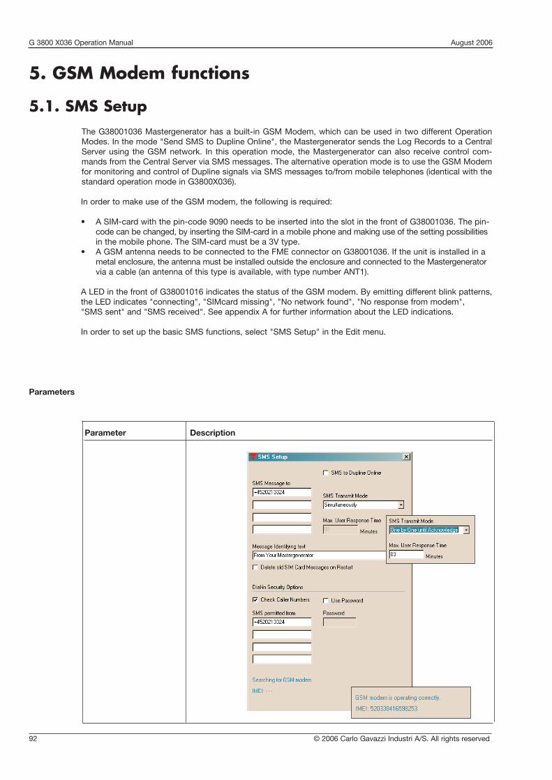
G 3800 X036 Operation Manual August 2006
92 © 2006 Carlo Gavazzi Industri A/S. All rights reserved
5. GSM Modem functions
5.1. SMS SetupThe G38001036 Mastergenerator has a built-in GSM Modem, which can be used in two different OperationModes. In the mode "Send SMS to Dupline Online", the Mastergenerator sends the Log Records to a CentralServer using the GSM network. In this operation mode, the Mastergenerator can also receive control com-mands from the Central Server via SMS messages. The alternative operation mode is to use the GSM Modemfor monitoring and control of Dupline signals via SMS messages to/from mobile telephones (identical with thestandard ope ration mode in G3800X036).
In order to make use of the GSM modem, the following is required:
• A SIM-card with the pin-code 9090 needs to be inserted into the slot in the front of G38001036. The pin-code can be changed, by inserting the SIM-card in a mobile phone and making use of the setting possibilitiesin the mobile phone. The SIM-card must be a 3V type.
• A GSM antenna needs to be connected to the FME connector on G38001036. If the unit is installed in ametal enclosure, the antenna must be installed outside the enclosure and connected to the Mastergeneratorvia a cable (an antenna of this type is available, with type number ANT1).
A LED in the front of G38001016 indicates the status of the GSM modem. By emitting different blink patterns,the LED indicates "connecting", "SIMcard missing", "No network found", "No response from modem","SMS sent" and "SMS received". See appendix A for further information about the LED indications.
In order to set up the basic SMS functions, select "SMS Setup" in the Edit menu.
Parameters
Parameter Description

© 2006 Carlo Gavazzi Industri A/S. All rights reserved 93
G 3800 X036 Operation Manual August 2006
Dial Out Phone-NumbersUp to 4 telephone numbers to which the SMS messages shall be sent can be entered. In case "Send SMS toDupline Online" is selected, only the telephone number of the Central Server needs to be entered. The countrycode must be included in the numbers (e.g. +4520213324).
It can be selected if an event-based SMS message shall be sent out to all the telephone numbers on the listsimultaneously, or if it shall be sent to the telephone numbers one by one, until an acknowledgement isreceived. Acknowledgement is performed by sending either a request or just an empty SMS message to theMastergenerator.
Parameter Description
SMS message to Up to 4 telephone numbers to which the SMS messages shall be sent can beentered. In case “Send SMS to Dupline Online” is selected, only the telephonenumber of the Central Server needs to be entered. The country code must beincluded in the numbers (eg +4520213324). It can be selected if an event-basedSMS message shall be sent out to all the telephone numbers on the list simulta-neously, or if it shall be sent to the telephone numbers one by one, until anacknowledgement is received. Acknowledgement is performed by sendingeither a request or just an empty SMS message to the Mastergenerator.
SMS to Dupline Online This Operation Mode must be selected if the GSM Modem shall be used tosend log records to a Central Server (Dupline-Online). In this case, only a fewparameters (like e.g. the phone number of the central server) need to beentered, and chapters 5.2 and 5.3 of this manual can be skipped.
Max. User Responsetime Only valid when "one by one to acknowledge" is selected. Here, the maximum
time the Mastergenerator shall wait for a response from a called number isentered. Otherwise the next number will be called.
Acknowledge: Either a request, a command, or an empty SMS (password mustbe included, if user password is selected).
Message Identifyingtext Optional SMS identifier text, that will be included in the SMS messages sent by
the Mastergenerator.
Delete old SIM CardMessages on Restart Check this box to erase "old" unread SMS messages on the SimCard, during
System power-Up. This is to prevent out-dated messages from interfering.
Check Caller Numbers Check this box to activate the Dial-In number protection. Any received SMS-message, contains the original phone-number. This number must exist in theDial-In numbers list, before any command is accepted by the Mastergenerator,when this option is selected.
SMS permitted from Enter the phone numbers, which are allowed to send control and read commands to the Mastergenerator. The country code must be included in thenumbers (eg +4520213324).
Use Password Check this box to activate the Password-protection. Any received SMS-message, will then be checked for the correct password, before any command is accepted by the Mastergenerator.
Password Type in a password with 4 characters, to be used in case "Use Password" isselected.
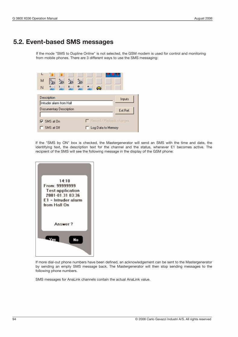
G 3800 X036 Operation Manual August 2006
94 © 2006 Carlo Gavazzi Industri A/S. All rights reserved
5.2. Event-based SMS messages
If the mode "SMS to Dupline Online" is not selected, the GSM modem is used for control and monitoringfrom mobile phones. There are 3 different ways to use the SMS messaging:
If more dial-out phone numbers have been defined, an acknowledgement can be sent to the Mastergeneratorby sending an empty SMS message back. The Mastergenerator will then stop sending messages to the following phone numbers.
SMS messages for AnaLink channels contain the actual AnaLink value.
If the "SMS by ON" box is checked, the Mastergenerator will send an SMS with the time and date, the identifying text, the description text for the channel and the status, whenever E1 becomes active. The recipient of the SMS will see the following message in the display of the GSM phone:

© 2006 Carlo Gavazzi Industri A/S. All rights reserved 95
G 3800 X036 Operation Manual August 2006
As it can be seen, it is possible to use either the channel reference directly (eg F4) or to use the descriptive textdefined for that channel.
The only channel types whose outputs are actually controlled directly ON or OFF by the SMS command arethe Toggle and Realtime channels. For push-button, Timer, Master, Roller Blind, Alarm Reset and Acknowledge channels, an SMS ON-command will initiate a pulse on the channel and thereby be able to trigger a function (eg a Master function or logic function). In this way, it is avoided that non-resettable channelactivations appear. An SMS OFF-command to these channels may not ensure that the channel output is turnedoff, since the output of the channel is also controlled by transmission on the channel.All other channel types cannot be controlled via SMS.
Note: The selected country language for on and off can be used as commands. However, we recommend theuser to use the English terms “ON” and “OFF”.
5.3. SMS Control commands and Requests for Dupline data
Commands for control or triggering of channel functions can be sent to the Mastergenerator via messages. Also, it is possible to send an SMS to the Mastergenerator with request for channel status. The Mastergenerator will then answer by sending back an SMS with the requested data. The format of theSMS commands and requests is shown in the example below:
With password optionControlling command ExamplePassword, Channel, argument 1234,F4,on
1234,F4,on1234,Alarm reset,on
Request Command ExamplePassword, Channel,? 1234,F3,?
1234,Siren,?
Without password optionControlling command ExampleChannel, argument F4,on
Alarm reset,onRequest Command ExampleChannel,? F3,?
Siren,?
NB: When using controlling commands on a channel, which is also configured to send a message whenchanging status, the message will also be sent to the GSM phone. Not all channel types can be controlled.

G 3800 X036 Operation Manual August 2006
96 © 2006 Carlo Gavazzi Industri A/S. All rights reserved
6. Data Logging Functions
6.1. GeneralThe Dupline Mastergenerator can be configured to log Digital signals, Analink signals, Multiplexed analog sig-nals and Counter values. The loggings can either be event or time based. Logged values are always stored innon-volatile memory to enable later retrieval. Simultaneously, at the actual time of logging, the values can besent to the Central Dupline-Online Database via GSM modem or the Internet. The Dupline-Online WebServerthen makes it possible for users with individual passwords to access own real-time and historical Dupline datavia the Internet.
6.2. Dupline-OnlineDupline-Online is a new Internet based concept for central and de-central monitoring and control of remotefacilities such as water works, power stations, apartment buildings, super markets, gas stations, car washmachines, elevators and unmanned railway stations. As the interface to the physical layer, the Dupline Fieldbus collects and controls all desired field data such as energy, water and gas consumption, alarms, light-ing, pumps, movement detectors, temperature, humidity, pressure, fluid levels etc. The DuplineMastergenerator can be programmed to log any combination of digital, analogue and counter signals basedon events or time and send them to the central Dupline-Online Database via the built-in GSM Modem (option-al) or via the Internet. Users can then access own real-time and historical data on their existing internet-connected IT-equipment by entering username and password on the homepage www.dupline-online.com. Dupline-Online services include alarm buffers with time and date tags on all events, trend curves for analogue signals, histograms with daily energy consumption, export of data to other systems, SMS alarms tomobile phones and buttons for switching signals at the remote site.
InternetConnection
InternetConnection
Internet
Data Collection via Internet Data Collection via GSM
Control Commands
Events /Logged data
SMSAlarms
Events /Logged data
Control Commands
Data base
User Access
Dupline® Fieldbus
Dupline® Fieldbus
EnergyMeter
CounterModule
SmokeDetector
TemperatureSensor
WaterLeakageDetector
Controller Controller
Digital I/O
AnalogI/O
CounterModule
InternetConnection
Central Server

© 2006 Carlo Gavazzi Industri A/S. All rights reserved 97
G 3800 X036 Operation Manual August 2006
The following steps are required for setting up a Mastergenerator for Dupline-Online operation:
• Select the media for transmitting the Log Records to the Central Server (GSM Modem or the Internet)• Select the desired Dupline addresses for event-based logging and enter text descriptions• Select the desired Dupline addresses for time-based logging and enter text descriptions, scaling factors,
engineering units and logging time intervals• Download the configuration file to the Mastergenerator• Generate a special Dupline-Online configuration file to be exported to the Central Server via the Internet
In the following sections of Chapter 6, it is described how to go through these steps (except for download ofthe configuration file to the Mastergenerator, which is described in sec. 1.2.1)
6.3. Dupline-Online Transmission Media
6.3.1. Using GSM ModemThe procedure for configuring the Mastergenerator for sending the Log Records to the Central Server via GSMModem is described in Chapter 5 (GSM Modem Functions).
6.3.2. Using the InternetIn order to use the Internet for sending the Log Records to the Central Server, "COM2 Operation Mode" mustbe set to "Automatic Data Logging" (see sections 4.4 and 4.6). Also, "COM2 Baud Rate" must be set to 9600.This is the only configuration required in the "Communication Setup" menu in order to set up Dupline-Onlineoperation. In terms of hardware, an external RS232-to-Ethernet converter (item number ETHCONV1) isrequired. The converter needs to be connected to COM2 of the Mastergenerator by means of the RS232 cableincluded in the ETHCONV1 package. The connection to the Ethernet is carried out by means of a standard Cat 5 Ethernet cable. In the majority of cases, this cabling is all that needs to be done to bring theconverter into operation, because it is pre-configured to send the Log Records to www.Dupline-Online.comand to be installed on a network with a dhcp server, which automatically assigns an IP address to it. If a dhcpserver is not available on the network, it is easy, however, to assign a specific IP address to the converter.It is always the Mastergenerator that initiates the communication from inside the local network by opening aTCP/IP socket connection to the Central Server. Because of this, there is usually no need to change any setupin the firewall in the network or in the converter. This is only necessary in those cases, where the firewall is fil-tering connections made from inside of the network, and this is quite unusual, because then free Internetaccess is also inhibited.
6.4. Event-based loggingThis is the standard (and only) logging method for Digital signals, but it can also be used for Analink signals.Whenever a Digital Dupline Address, which has been configured for logging, changes status, a Log Record isgenerated and saved in non-volatile memory. If configured to do so (see section 6.2 and 6.3), the Master -generator will also send the Log record via GSM or the Internet to the Central Dupline-Online WebServer,where it is saved in a database. The Log Record contains the Address, the new status of the signal (ON orOFF) and time/date/year of the event. Event-based logging of an Analink signal takes place whenever the value crosses the limits defined in the setup of the Analink address. The Log Record contains the Address, theAnalink value and time/date/year of the event.
The selection of which signals shall be logged as events is performed under the setup menu for each individual channel.

G 3800 X036 Operation Manual August 2006
98 © 2006 Carlo Gavazzi Industri A/S. All rights reserved
Menu Item: Explanation:
Description This text is used as description for the selected channel address when accessing the logged data via Dupline-Online. Other languages can be inserted in the 3-language menu.
Log Data to GSM
6.5. Time-based logging
6.5.1. IntroductionThis method can be used for Analink signals, Multiplexed analog signals and Counter values. For each of these3 signal categories, a logging time interval in the range from 5 minutes to 1 month can be defined. The signalswithin each category are then logged on a continuous basis according to the selected time interval. The LogRecord contains the Address, all the logged values within this category and time/date/year of the Log Record.
6.5.2. Time-based logging of Analink channelsAs described in sec 6.4, the selection of which Analink channels shall be included in time-based logging isdone under the individual channel set-up by choosing the "Log Data to GSM" option. The Analink Log TimeInterval must be defined in the menu "Analink Log set-up".
Menu Item: Explanation:
Log interval Defines the time interval between Analink Log Records.
Date Only relevant when Analink signals are logged on a monthly basis. Defines the day of the month on which the Log Record shall be made.
Hour and Minute: Only relevant when Analink signals are logged on daily basis. Defines the time of the day on which the Log Record shall be made.
If selected for a digital channel, the Mastergenerator will send alog record to the Dupline-Online Webserver each time thisDupline channel changes status from OFF to ON or ON to OFF.If selected for an Analink channel, the Mastergenerator willsend a Log Record each time the Analink value crosses one ofthe user-defined limits, and whenever the log interval timeselected in the menu “Analink Log Set-up” (see section 6.5) haspassed since last time-based log.Note: The menu Item text is dynamic, so if “automatic logging”has been selected for COM2 int he Communication setup-menu, the menu text will be “Log Data to COM2”.

© 2006 Carlo Gavazzi Industri A/S. All rights reserved 99
G 3800 X036 Operation Manual August 2006
Menu Item: Explanation:
Description This text is used as description for the selected Counter address when accessing the logged data via Dupline-Online.
Factor Defines the ratio of pulses per unit of measure. If eg an Energy-meter with 640 pulses/kWh is used, then the figure 640 must be entered to get the correct kWh reading from the Dupline-Online database.
6.5.3. Time-based logging of CountersThe set-up for the logging of Counter values is performed in the menu “Mux Counters Log Set-up”. A tableshowing the counter addresses available (as defined in the menu “Counter and Mux Analog Setup”) is usedfor selecting the Counter addresses to be logged, and for metering text descriptions, scaling for these coun-ters and engineering units. Also, the Log Time Interval for Counters is defined in this menu.
A Counter address is selected for logging by double-clicking on it with the mouse. The color of the associat-ed field will then change to Cyan, and this indicates that the parameters entered under "Description", "Factor"and "Unit of measure" will now be assigned to this Counter address. The color of the field turns green whenanother menu or Counter address is selected, to indicate that the Counter address has now been configuredfor logging. To change a parameter for a Counter address, click on the associated green field and it will changecolor to cyan to indicate that the parameters shown belongs to this Counter address and that it is ready forchanges.
To disable logging for a Counter, double-click on the associated green field.

G 3800 X036 Operation Manual August 2006
100 © 2006 Carlo Gavazzi Industri A/S. All rights reserved
6.5.4. Time-based logging of Multiplexed Analog dataThe set-up for the logging of Multiplexed Analog data is performed in the menu "Mux Analog Log Set-up". Atable showing the Mux Analog addresses available (as defined in the menu "Counter and Mux Analog Setup")is used for selecting the Mux Analog addresses to be logged, and for entering text descriptions, scaling forthese analog signals and engineering units. Also, the Log Time Interval for Mux Analog signals is defined inthis menu.A Mux Analog address is selected for logging by double-clicking on it with the mouse. The color of the associated field will then change to Cyan, and this indicates that the parameters entered under "Description","Range lo", "Range Hi" and "Unit of measure" will now be assigned to this Mux Analog address. The color ofthe field turns green when another menu or Mux Analog address is selected, to indicate that the Mux Analogaddress has now been configured for logging. To change a parameter for a Mux Analog address, click on theassociated green field and it will change color to cyan to indicate that the parameters shown belongs to thisMux Analog address and that it is ready for changes.To disable logging for a Mux Analog address, double-click on the associated green field.
Menu Item: Explanation:
Unit of measure Defines the unit of measure for the Counter. If eg an Energy-meter with 640 pulses/kWh is used, then the “kWh” must be entered to get the correct reading from the Dupline-online database.
Log interval Defines the time interval between Counter log Records.
Date Only relevant when a Counter is logged on a monthly basis. Defines the day of the month the Log Record shall be made.
Hour and Minute Only relevant when an Analink signal is logged on a daily basis. Defines the time of the day the Log Record shall be made.

© 2006 Carlo Gavazzi Industri A/S. All rights reserved 101
G 3800 X036 Operation Manual August 2006
6.6. Export of the Configuration to the Dupline-OnlineWebserver
The configured logging functions with addresses, descriptions, scaling, units of measure etc. and the uniqueID code of the Mastergenerator need to be uploaded to the Dupline-Online Webserver in order to ensureaccept of Log Records received from this ID-code and correct handling of data. Therefore, after the configuration of the Mastergenerator has been finalized, "Export Configuration" needs to be activated in theFile menu in order to create this file.Registration of the Mastergenerator for Dupline-Online operation is performed by following the instructions onthe homepage www.dupline-online.com . The registration procedure is very simple, because the "export con-figuration" file will automatically be requested, and this file contains all the information needed by the Dupline-Online Webserver. After registration the system is ready to operate.
6.7. Dupline-Online Data SecuritySeveral means of ensuring data security have been implemented in the Dupline-Online system in order to provide a reliable and safe collection and protection of logged data:• If Log Records are transmitted via the Internet, the Mastergenerator will continuously check if
acknowledge telegrams for the individual Log Records are received from the Dupline-Online Webserver. If not, the relevant Log Records will be re-transmitted. The re-transmission buffer has capacity to hold up to 256 unacknowledged Log Records
• Log Records transmitted via the Internet are encrypted to inhibit hackers from inserting false Log Records/Control commands
• If Log Records are transmitted via GSM, the Mastergenerator will wait for an acknowledge message from the GSM network provider. If not, the relevant Log Records will be re-transmitted until an acknowledge message is received
• When GSM is used, it is checked that the sending telephone number for a Log Record or Control Command is valid
• Data Access via the Dupline-Online Webserver is protected by user names and passwords• A back-up for the Dupline-Online Database is generated on a daily basis• The Dupline-Online Webserver is protected by a comprehensive firewall
Menu Item: Explanation:
Description This text is used as description for the selected Mux Analog address when accessing the logged data via Dupline-Online.
Range Lo Defines the lowest value of the analog input signal. Used for scaling of the Mux Analog value. If eg the analog signal comes from a level meter with the range 0-500 cm, then the “Range Lo” value is 0.
Range Hi Defines the highest value of the analog input signal. Used for scaling of the Mux Analog value. If eg the analog signal comes from a level meter with the range 0-500 cm, then the “Range Hi” value is 500.
Unit of measure Defines the unit of measure for the Mux Analog.
Log interval Defines the time interval between Mux Analog Log Records.
Date Only relevant when a Mux Analog is logged on a monthly basis. Defines the day of the month the Log Record shall be made.
Hour and Minute Only relevant when an Analink signal is logged on a daily basis. Defines the time of the day the Log Record shall be made.

G 3800 X036 Operation Manual August 2006
102 © 2006 Carlo Gavazzi Industri A/S. All rights reserved
7. Radio Modem Functions
7.1. GeneralThe Mastergenerator has a built-in driver for control of an external Radio Modem, which can be used to createwireless links where no cable is available in parts of an installation. One Mastergenerator must be defined asthe central Mastergenerator and up to 32 Mastergenerators can be defined as remote Mastergenerators. Thecentral Mastergenerator is continuously polling and updating the Dupline data from all remoteMastergenerators via the radio modem network, and in this way it makes the entire system operate as one bigDupline network. Apart from increased reaction time (depending on the number of remote Mastergenerators),the system will operate as if it was one Mastergenerator connected to all the I/O-modules with cable. TheMastergenerator supports the Radio Modem type 2ASxE and all 3AS types from the Finnish manufacturerSATEL (www.satel.fi). These are not supplied by Carlo Gavazzi, but are available with local support worldwide.Find below an application diagram for the Radio Modem option. Note: Analink modules cannot be used withRadio Modems.
The Radio Modem must be connected to the COM2 of the Mastergenerator. For serial cable pin connections,please refer to the Mastergenerator datasheet. The baud rate selected for COM2 must correspond to the baudrate used by the radio modems and the other Mastergenerators in the network. The central Mastergenerator must be defined for "Radio Modem central" function for COM2, while the remoteMastergenerators must be defined as "Radio modem substation". The central Mastergenerator can be configured for the usual intelligent functions, and it can also be connected via COM1 or the RS485 port to a
PLC or PC. The remote Mastergenerators, however, cannot be configured for any intelligent function1). Theywill simply operate as Radio Modem interfaces. The system can handle all types of digital, analog (incl. multi-plexed) and counter values, except for Analink values. The configuration of the Radio Modem function is per-formed in the menu "Edit" under "Communication setup".
1) For the remote Mastergenerators, the logic functions are available to enable access to the Mastergenerators’ digital inputs and outputs.

© 2006 Carlo Gavazzi Industri A/S. All rights reserved 103
G 3800 X036 Operation Manual August 2006
Modem turn-around time
Substation max.response time
No. of substations
Select groups for exchange of Mux analog
Parameter Description
Defines the time delay the Mastergenerator uses when changing betweenreceiving and transmitting. This can be used to adapt to individual radiomodem types, which may have different requirements for this parameter. Thedefault value of 100 ms will work in most cases.
Defines the time the central Mastergenerator will wait for an answer from asubstation. If the Mastergenerator does not receive an answer within this timeit continues to the next substation. The default time is 1 s, which is fine formost applications, but longer time may be needed if repeater stations areused on the radio modems.
Defines the number of substations connected via radio modem to the centralMastergenerator. Important Note: The Mastergenerators configured as "Radio modem substa-tion must be given the ID numbers from 1 and onwards. Example: When "Noof substations" are set to 3, then the 3 Mastergenerators configured as "radiomodem substation" must be given the ID numbers 1, 2 and 3 respectively.
If multiplexed analog I/O’s are used in the radio modem system, then it is necessary to define which "channel group pairs" are used for this purpose.This is simply done by selecting the relevant check boxes. It is only possibleupon prior setup of Multiplex-count under the menu Counters and Mux AnalogSetup.
Parameter: Radio Modem Central
7.2. Setup of Radio Modem Central

G 3800 X036 Operation Manual August 2006
104 © 2006 Carlo Gavazzi Industri A/S. All rights reserved
7.3. Setup of Radio Modem Substation
Parameter: Radio Modem Substation
Parameter Description
Clear data upon lossof radio communication Per default, the substations maintain the last received Dupline output data no
matter how long time has passed since the last telegram was received from thecentral Mastergenerator. If "Clear data upon loss of radio communication" ischecked, then the output data will be cleared when the time-out defined in"Time to Data-clear" has run out.
Clear data after Defines the time-out when "Clear data upon loss of radio modem communication" is selected.

© 2006 Carlo Gavazzi Industri A/S. All rights reserved 105
G 3800 X036 Operation Manual August 2006
Off
No
sup
ply
No
carr
ier
OK
OK
OK
or
No
Mod
em in
stal
led
1 b
link
3 p
ause
sna
Con
nect
ing
2 b
link
2 p
ause
sna
Sim
Car
d m
issi
ng
3 b
link
5 p
ause
sna
No
Net
wor
k fo
und
4 b
link
4 p
ause
sna
Dat
a E
rror
Dow
nloa
d
5 b
link
3 p
ause
sna
Pro
gram
min
g fa
iled
No
resp
onse
fro
m m
odem
Sho
rtci
rcui
t R
eset
Con
tinuo
us b
link
nare
qui
red
Pro
gram
min
g
Net
w.C
omm
1 b
link
naS
ent
SM
S
2 b
link
naR
ecei
ved
SM
S
ON
OK
OK
Up
-/D
own-
Load
ing
Flas
hing
na =
Not
ap
plic
able
Bla
nks
= U
nuse
d
Appendix A
Whe
n m
odem
inst
alle
d
and
det
ecte
d
Blin
k p
atte
rnS
upp
ly L
ED
Dup
line
LED
RS
232
RS
485
GS
MC
om1/
Com
2
Mast
ergen
erato
r G
3800 x
0x
x L
ED indic
ation

Mastergenerator ModBus Functions
2004 Carlo Gavazzi Industri A/S. All rights reserved. 106
Modbus-RTU interface
Modbus-RTU is implemented with the function of a slave. The following Modbus functions aresupported: 01, 02, 03, 05, 06 and 16. All 128 Dupline ® Digital, Analink, Counter, and BCD channelsare placed as follows:
Modbus-RTU Functions implemented in the Master Generator
Read Functions
Function Code 01: Read Output Table Bit (Data to Receivers)
RegisterAddress
Register 8 bit
Dec Hex1280 500 A1 00=OFF Bit1281 501 A2 01=ON Bit
Bit1407 57F P8 Bit
Function Code 02: Read Input Table Bit (Data from transmitters)
RegisterAddress
Register 8 bit
Dec Hex1536 600 A1 00=OFF Bit1537 601 A2 01=ON Bit
Bit1663 67F P8 Bit
Function Code 03: Read Multiple Registers
RegisterAddress
Register 16 bit
Dec Hex Hi Lo0 0 B8..B1 A8..A1 Digital1 1 D C Digital. . . . .6 6 N M Digital7 7 P O Digital
RegisterAddress
Register 16 bit
Dec Hex Hi Lo16 10 B8..B1 A8..A1 Digital17 11 D C Digital. . . . .
26 16 N M Digital27 17 P O Digital
256 100 A1 0 0..255 Analink257 101 A2 0 0..255 Analink258 102 A3 0 0..255 Analink
. . . 0 0..255 Analink382 17E P7 0 0..255 Analink383 17F P8 0 0..255 Analink
512 200 0 0..99 0..99 0..99 0..99 Counter514 202 1 0..99 0..99 0..99 0..99 Counter516 204 2 0..99 0..99 0..99 0..99 Counter
0..99 0..99 0..99 0..99 Counter764 2FC 126 0..99 0..99 0..99 0..99 Counter766 2FE 127 0..99 0..99 0..99 0..99 Counter
Reads information previously written by a Modbus commandfor transmission on DuplineReading of only 1 register at a time is allowed.Value : 0 or 1
Reads Dupline Output-Status.Reading of only 1 register at a time is allowed.Value : 0 or 1
Reads Dupline Output status.Reading of 1 to 8 registers possible.
If an attempt is made to read from a start-address and the number of registersexceeds the allowed register range, no answer will be made, as this isinterpreted as an illegal function
AnaLink values are readable. Irrespective of the configuration of the channels.If a value is read as FFFFh, the Sensor is not present.Reading of 1 to 32 registers possible
Counter value only valid if Counters are selected.Value read in BCDReading of 1 to 32 registers allowed.
Reads Dupline Input status .Reading of 1 to 8 registers possible.
If an attempt is made to read from a start-address and the number of registersexceeds the allowed register range, no answer will be made, as this isinterpreted as an illegal function

Mastergenerator ModBus Functions
2004 Carlo Gavazzi Industri A/S. All rights reserved. 107
Dec Hex Mux Hi Lo Value784 310 0 HI LO CD-0 Input Table785 311 1 HI LO CD-1 Input Table786 312 2 HI LO CD-2 Input Table787 313 3 HI LO CD-3 Input Table
- - - - - - Input Table799 31F F HI LO CD-F Input Table800 320 0 H! LO EF-0 Input Table815 32F F HI LO EF-F Input Table816 320 0 HI LO GH-0 Input Table831 33F F HI LO GH-F Input Table832 340 0 HI LO IJ-0 Input Table847 34F F HI LO IJ-F Input Table848 350 0 HI LO KL-0 Input Table863 35F F HI LO KL-F Input Table864 360 0 HI LO MN-0 Input Table879 36F F HI LO MN-F Input Table880 370 0 HI LO OP-0 Input Table895 37F F HI LO OP-15 Input Table
4096 1000 B8-B1 A8-A1 Digital4097 1001 D C Digital
. . Digital4103 1007 P O Digital
4112 1010 B8-B1 A8-A1 Digital4113 1011 D C Digital
Digital4119 1007 P O Digital
4880 1310 0 HI LO CD-0 Input Table4881 1311 1 HI LO CD-1 Input Table4882 1312 2 HI LO CD-2 Input Table4883 1313 3 HI LO CD-3 Input Table
- . - - - - Input Table4895 131F F HI LO CD-F Input Table4896 1320 0 H! LO EF-0 Input Table4911 132F F HI LO EF-F Input Table4912 1330 0 HI LO GH-0 Input Table4929 133F F HI LO GH-F Input Table4930 1340 0 HI LO IJ-0 Input Table4943 134F F HI LO IJ-F Input Table4944 1350 0 HI LO KL-0 Input Table4959 135F F HI LO KL-F Input Table4960 1360 0 HI LO MN-0 Input Table4975 136F F HI LO MN-F Input Table4976 1370 0 HI LO OP-0 Input Table4990 137F F HI LO OP-15 Input Table
8192 2000 HI LO Substatations1..16
Status
8193 2001 HI LO Substations 17..32 Status
8194 2002 HI LO Substations 1.. 16 Status8195 2003 HI LO Substations 17..32 Status
Dec Hex Hi Lo8208 2010 Hour Minute 0..23 0..59 Setup8209 2011 Second
sDay ofweek
0..59 0..FF Setup
8210 2012 Month Date 1..12 1..31 Setup8211 2013 Year Year 0..99 0..99 Setup
Multiplexed analog Read Input Table
Registers 0300H to 037FH BCD-VALUESResisters 0400H to 047FH BINARY-VALUES
Multiplexed analog values only valid if Multiplexer is selectedReading of 1 to 32 registers possible
Dupline group AB holds the actual Mux-address on the 4 most significant bits.The remaining bits holds the digital transmit information from channel A5..B8
Active Devices found in the RS485 Network32 bits indicating the presence of slaves in the NetworkRegister 2002h, MSB = Slave no 00 (central=0). LSB = Slave no 15Register 2003h, MSB = Slave no 16 LSB = Slave no31.2 Registers.
Reads information previously written by a Modbus command for transmission onDuplineReading of 1 to 8 registers possible.
If an attempt is made to read from a start-address and the number of registers exceedsthe allowed register range, no answer will be made, as this is interpreted as an illegalfunction
Reads information previously written by a Modbus command for forced output onDupline.Reading of 1 to 8 registers possible.
If an attempt is made to read from a start-address and the number of registers exceedsthe allowed register range, no answer will be made, as this is interpreted as an illegalfunction
Multiplexed Analog Read Output Table
Registers 1300H to 137FH BCD-VALUESResisters 1400H to 147FH BINARY-VALUES
Multiplexed analog values only valid if Multiplexer is selectedReading of 1 to 32 registers possible
In the Binary Data-area, the transmitted data are checked against valid BCD coding and also the control-bits from the Analog transmitter.Reading an “FFFF” indicates an invalid value or a non-existing analog transmitter.Eg. Reading BCD data on Group C, then the channels C1 and C2 has to be active, before a binary valueare read. This is done automatically by the analog transmitters.
Active Devices found in Radio-Modem Network. (When configured as Radio-modem Central)32 bits indicating the presence of a Radio-Modem sbustation.Register 2000h, MSB = Substation no 00 (central=0). LSB = Substation no 15Register 2001h, MSB = Substation no 16 LSB = Substation no31.2 Registers.
Read Generators internal 24 Hour clock.Format: hh.mm, ss,dd,MM,DD,YYYY
Day of week: 1 Monday ..7 Sunday.The Data format is BCD
Note: All 4 Registers must be read simultaneously.

Mastergenerator ModBus Functions
2004 Carlo Gavazzi Industri A/S. All rights reserved. 108
16384 4000 HI LO A1 Limit 1 Low Setup16385 4001 HI LO A1 Limit 1 High Setup16386 4002 HI LO A1 Limit 2 Low Setup16387 4003 HI LO A1 Limit 2 High Setup16388 4004 HI LO A2 Limit 1 Low Setup
4008 HI LO A3 Limit 1 Low Setup16416 4020 HI LO B1 Limit 1 Low Setup
16892 41FC HI Lo P8 Limit 1 Low Setup16893 41FD HI Lo P8 Limit 1 High Setup16894 41FE HI Lo P8 Limit 2 Low Setup16895 41FF HI Lo P8 Limit 2 High Setup
16896 4200 HI LO A1 on-delay tb Setup16897 4201 HI LO A1 on-delay Setup16898 4202 HI LO A1 off-delay tb Setup16899 4203 HI LO A1 off Delay Setup16900 4204 HI LO A2 on-delay tb Setup16904 4208 HI LO A3 on-delay tb Setup16928 4220 HI LO B1 on-delay tb Setup
17404 43FC HI Lo P8 on-delay tb Setup17405 43FD HI Lo P8 on-delay Setup17406 43FE HI Lo P8 off-delay tb Setup17407 43FF HI Lo P8 off delay Setup
24576 6000 A1 HI: hour Lo: min On-time1 Setup24577 6001 A1 hour Min Off-time 1 Setup24578 6002 A1 xxx Days Day select 1 Setup24579 6003 A1 xxx xxx Don’t-care Setup24580 6004 A1 HI: hour Lo: min On-time 2 Setup24581 6005 A1 hour Min Off-time 2 Setup24582 6006 A1 xxx Days Day select 2 Setup24583 6007 A1 xxx xxx Don’t-care Setup24584 6008 A1 HI: hour Lo: min On-time3 Setup24585 6009 A1 hour Min Off-time 3 Setup24586 600A A1 xxx Days Day select 3 Setup25587 600B A1 xxx xxx Don’t-care Setup25588 600C A1 HI: hour Lo: min On-time 4 Setup25589 600D A1 hour Min Off-time 4 Setup25590 600E A1 xxx Days Day select 4 Setup25591 600F A1 xxx xxx Don’t-care Setup25592 6010 B1 HI: hour Lo: min On-time 1 Setup
26620 67FC P8 HI: hour Lo: min On-time 4 Setup26621 67FD P8 hour Min Off-time 4 Setup26622 67FE P8 xxx Days Day select 4 Setup26623 67FF P8 xxx xxx Don’t-care Setup
49408 C100 A1 HI LO Pulse count49409 C101 A2 HI LO Pulse count49410 C102 A3 HI LO Pulse count49411 C103 A4 HI LO Pulse count
49534 C17E P7 HI LO Pulse count49535 C17F P8 HI LO Pulse count
Read AnaLink channels Set-Point values, as configured or as set by a previousModBus write-command.
Legal Values lies in the range from 0 to 255, and must be scaled according tothe type of analink signal.
Responds only, if channel is configured for AnaLink channeltype.4 Registers per Setup.Reading of 1 to 32 registers possible
If an attempt is made to read from a start-address and the number of registersexceeds the allowed register range, no answer will be made, as this is interpretedas an illegal function
Read Realtime channels Set-up values, as configured or as set by a previousModBus write-command.
Read On/Off times and day/holiday setup.
Responds only, if channel is configured for a Realtime channeltype.16 Registers per Setup.Reading of 1 to 32 registers possible
If an attempt is made to read from a start-address and the number of registersexceeds the allowed register range, no answer will be made, as this is interpretedas an illegal function.
Hour and Minutes in BCDIf Hour –value is read as FFh, then this setting is not active.Days: MSB: Holiday
LSB: Monday
Read Pulse-counter Latched (Frozen) values
If an attempt is made to read from a start-address and the number of registersexceeds the allowed register range, no answer will be made, as this is interpretedas an illegal function.
Countvalue in BCD from 0 to 9999
Reading of 1 to 32 registers possible
Read timer channels Set-up ON and OFF delays, as configured or as set by aprevious ModBus write-command.
the delay-tb, if zero, the delay is counted in seconds. It tb = 1, the delay iscounted in minutes.
Responds only, if channel is configured for Timer channel type.4 Registers per Setup.Reading of 1 to 128 registers possible
If an attempt is made to read from a start-address and the number of registersexceeds the allowed register range, no answer will be made, as this is interpretedas an illegal function.

Mastergenerator ModBus Functions
2004 Carlo Gavazzi Industri A/S. All rights reserved. 109
Function Code 05: Set single Output Bit
RegisterAddress
Register 8 bit
Dec Hex5376 1500 A1 00=Off Bit5377 1501 A2 01=On Bit
. . . Bit5503 157F P8 Bit
12288 3000 0 HI LO Bit12289 3001 1 HI LO Bit12290 3002 2 HI LO Bit12291 3003 3 HI LO Bit
4 Hi Lo BitBit
12414 307E 126 HI LO Bit12415 307F 127 HI LO Bit
12544 3100 0 HI LO Bit12545 3101 1 HI LO Bit12546 3102 2 HI LO Bit12547 3103 3 HI LO Bit
4 Hi Lo BitBit
12670 317E 126 HI LO Bit12671 317F 127 HI LO Bit
49152 C000 0 HI LO Bit49153 C001 1 HI LO Bit49154 C002 2 HI LO Bit49155 C003 3 HI LO Bit
4 Hi Lo BitBit
49278 C07E 126 HI LO Bit49279 C07F 127 HI LO Bit
Function Code 06: Preset Single Register
RegisterAddress
Register 8 bit Format
Dec Hex4096 1000 B8..B1 A8..A1 Digital4097 1001 D C Digital
. . . . Digital4103 1007 P O Digital
RegisterAddress
Register 8 bit Format
Dec Hex12288 3000 B8..B1 A8..A1 Digital12289 3001 D C Digital
. . . . Digital12295 3007 P O Digital
Reset Multiplexed counter.
A write of a 1, to any address, will reset the multiplexed counter.Writing of only 1 register at a time is allowed.Value : 0 or 1
Write a bit, for statically activation of a Dupline channel.This command will start the configured function, on that channel, as if atransmitter on that channel are held activated.
Writing of only 1 register at a time is allowed.Value : 1 start the function, and keep it activatedValue: 0 Release the function.
Write data for Output on Dupline channels.
Writing 1’s will start the configured function, on that channel, as if atransmitter were activated on the corresponding channels.
Write data for momentary activation of a Dupline Channel
This command will start the configured function, on that channel, as if atransmitter on that channel were activated for a short pulse.Writing of only 1 register at a time is allowed.
Bits set, trigger the corresponfing channelsBits clear, has no function.
Write a bit, for momentary activation of a Dupline Channel
This command will start the configured function, on that channel, as if atransmitter on that channel were activated for a short pulse.Writing of only 1 register at a time is allowed.
Value 1: trigger the functionValue 0: allowed, but has no function.
Write a bit, for set or reset of a Dupline Channel
This command will enforce the channel into On or Off , as if a masterfunctionwere activated on the channels.Writing of only 1 register at a time is allowed.
Value 1: SetValue 0: Reset

Mastergenerator ModBus Functions
2004 Carlo Gavazzi Industri A/S. All rights reserved. 110
Function Code 16: Preset Multiple Registers
Dec Hex Hi Lo4096 1000 B8-B1 A8-A1 Digital4097 1001 D C Digital
. . . . Digital4103 1007 P O Digital
Dec Hex Hi Lo4112 1010 B8-B1 A8-A1 Digital4113 1011 D C Digital
. . . . Digital4119 1017 P O Digital
4880 1310 0 HI LO CD-0 Output Table4881 1311 1 HI LO CD-1 Output Table4882 1312 2 HI LO CD-2 Output Table4883 1313 3 HI LO CD-3 Output Table
- . - - - - Output Table4895 131F F HI LO CD-F Output Table4896 1320 0 H! LO EF-0 Output Table4911 132F F HI LO EF-F Output Table4912 1330 0 HI LO GH-0 Output Table4929 133F F HI LO GH-F Output Table4930 1340 0 HI LO IJ-0 Output Table4943 134F F HI LO IJ-F Output Table4944 1350 0 HI LO KL-0 Output Table4959 135F F HI LO KL-F Output Table4960 1360 0 HI LO MN-0 Output Table4975 136F F HI LO MN-F Output Table4976 1370 0 HI LO OP-0 Output Table4990 137F F HI LO OP-15 Output Table
Output Table
Dec Hex Hi Lo8192 2000 Hour Minute 0..23 0..59 Setup8193 2001 Second
sDay ofweek
0..59 0..FF Setup
8194 2002 Month Date 1..12 1..31 Setup8195 2003 Year Year 0..99 0..99 Setup
16384 4000 HI LO A1 Limit 1 Low Setup16385 4001 HI LO A1 Limit 1 High Setup16386 4002 HI LO A1 Limit 2 Low Setup16387 4003 HI LO A1 Limit 2 High Setup16388 4004 HI LO A2 Limit 1 Low Setup
4008 HI LO A3 Limit 1 Low Setup16416 4020 HI LO B1 Limit 1 Low Setup
16892 41FC HI Lo P8 Limit 1 Low Setup16893 41FD HI Lo P8 Limit 1 High Setup16894 41FE HI Lo P8 Limit 2 Low Setup16895 41FF HI Lo P8 Limit 2 High Setup
16896 4200 HI LO A1 on-delay tb Setup16897 4201 HI LO A1 on-delay Setup16898 4202 HI LO A1 off-delay tb Setup16899 4203 HI LO A1 off Delay Setup16900 4204 HI LO A2 on-delay tb Setup16904 4208 HI LO A3 on-delay tb Setup16928 4220 HI LO B1 on-delay tb Setup
17404 43FC HI Lo P8 on-delay tb Setup17405 43FD HI Lo P8 on-delay Setup17406 43FE HI Lo P8 off-delay tb Setup17407 43FF HI Lo P8 off delay Setup
Set Generators internal 24 Hour clock.Format: hh.mm, ss,dd,MM,DD,YYYY
Day of week: 1 Monday ..7 Sunday.The Data format is BCD and should hold a valid date and time.If format is wrong, the command is not responded to.
Note: All 4 Registers must be written simultaneously.
Write AnaLink channels Set-Point values.
Legal Values lies in the range from 0 to 255, and must be scaled according tothe type of analink signal.
Responds only, if channel is configured for a Realtime channeltype.4 Registers per Setup.Writing of 1 to 32 registers possible
If an attempt is made to read from a start-address and the number of registersexceeds the allowed register range, no answer will be made, as this is interpretedas an illegal function.
The changes are stored permanently in the system configuration memory.
Multiplexed Analog Write Output Table (AO)
Registers 1300H to 137FH BCD-VALUESResisters 1400H to 147FH BINARY-VALUES
Multiplexed analog values only valid if Multiplexer is selectedWriting of 1 to 32 registers possible
Write data for Output on Dupline channels.
Writing 1’s will start the configured function, on that channel, as if a transmitterwere activated on the corresponding channels.
Writing of 1 to 8 registers possible.
If an attempt is made to write to a start-address and the number of registers exceedsthe allowed register range, no answer will be made, as this is interpreted as an illegalfunction
Write data for Forcing the Output on Dupline channels.Writing 1’s will force the channels on, as if a masterfunction activated thecorresponding channels.
Writing of 1 to 8 registers possible.
If an attempt is made to write to a start-address and the number of registers exceedsthe allowed register range, no answer will be made, as this is interpreted as an illegalfunction
Write timer channels configuration for ON and OFF delays
Delays < 12. hours counts in seconds and delay-tb are set to 0Dalays >12 hours counts in Minutes and delay-tb are set to 1
Responds only, if channel is configured for Timer channel type.4 Registers per Setup.Reading of 1 to 128 registers possible
If an attempt is made to read from a start-address and the number of registers exceeds theallowed register range, no answer will be made, as this is interpreted as an illegal function.
The changes are stored permanently in the system configuration memory.

Mastergenerator ModBus Functions
2004 Carlo Gavazzi Industri A/S. All rights reserved. 111
24576 6000 A1 HI: hour Lo: min On-time1 Setup24577 6001 A1 hour Min Off-time 1 Setup24578 6002 A1 xxx Days Day select 1 Setup24579 6003 A1 xxx xxx Don’t-care Setup24580 6004 A1 HI: hour Lo: min On-time 2 Setup24581 6005 A1 hour Min Off-time 2 Setup24582 6006 A1 xxx Days Day select 2 Setup24583 6007 A1 xxx xxx Don’t-care Setup24584 6008 A1 HI: hour Lo: min On-time3 Setup24585 6009 A1 hour Min Off-time 3 Setup24586 600A A1 xxx Days Day select 3 Setup25587 600B A1 xxx xxx Don’t-care Setup25588 600C A1 HI: hour Lo: min On-time 4 Setup25589 600D A1 hour Min Off-time 4 Setup25590 600E A1 xxx Days Day select 4 Setup25591 600F A1 xxx xxx Don’t-care Setup25592 6010 B1 HI: hour Lo: min On-time 1 Setup
26620 67FC P8 HI: hour Lo: min On-time 4 Setup26621 67FD P8 hour Min Off-time 4 Setup26622 67FE P8 xxx Days Day select 4 Setup26623 67FF P8 xxx xxx Don’t-care Setup
Dec Hex Hi Lo Pulse Count8192 A00
0AAh 55h Reset
8193 A001
AAh 55h Freeze
Write Realtime channels Set-up values
Write On/Off times and day/holiday setup.
Hour and Minutes in BCDTo disable an on or off setting , write 0FFh to the Hour-byte
Days: MSB: HolidayLSB: Monday
Responds only, if channel is configured for a Realtime channeltype.16 Registers per Setup.Writing of 1 to 32 registers possible
If an attempt is made to read from a start-address and the number of registersexceeds the allowed register range, no answer will be made, as this is interpretedas an illegal function.
The changes are stored permanently in the system configuration memory.
Reset and Freeze command, for Pulse-countersThe reset command, clears all pulse-counters.The Freeze command, latches the actual counter-values , so they may be read by theFC 03 address C100h.
Only when value is AA55h, the commands are executed.1 Register only.

© 2004 Carlo Gavazzi Industri A/S. All rights reserved 112
G 3800 X036 Operation Manual
Appendix C
RS485 Communications
The cableRS485 communication cable is a shielded, twisted pair cable. Many cable manufacturers supply cable meeting the RS485 standard (e.g. Belden 9841). Other cabling media such as telephone cable, coaxial cableand multi-core wires could prove problematic and not provide satisfactory performance.
TopologyThe cable must be installed to pass close by each node. Stubs (cables joining the node to the cable) or stars(multiple cable segments brought back to a single point) are not permitted.
Cable LengthThe maximum length of a single cable run is 1200 meters.
Connection of the cable shieldThe shield of the RS485 cable establishes a reference voltage for the RS485 signal conductors. For this reason the cable shield must be connected to V- (terminal 32) on each Master Generator on the network. The"screen pig-tails" going into the terminals should be as short as possible. The shield should be continuousthroughout the installation, but only connected to proper ground at one point with an earth contact resistanceof less than 2 Ω.
Termination and Fail-safe resistorsThe cable must be terminated at each end. This is to prevent reflections which would disrupt communica-tions. Also, the use of so-called fail-safe pull-up and pull-down resistors in one of the ends is required toensure safe and reliable communication. The Master Generator has built-in termination and fail-safe resistors.The termination resistor is connected to terminal 30 (B) and terminal 27 internally. Therefore pin 27 needs tobe connected to pin 31 (A) in both of the cable endings in order to make the terminations effective.The fail-safe resistors shall only be used in one cable end. By connecting pin 31 (A) to pin 29, and by connecting pin 30 (B) to pin 28 the fail-safe resistors are made effective.
Cable IsolationThe communication cable must not be run in cable trays carrying power wiring nor in close proximity to power wiring. Current surges in power wiring due to high equipment starting currents or to faults can disruptcommunications.
Wiring diagramFind below an example of a complete wiring diagram for a system with 3 Master Generators connected in anRS485 network.
1 2 3 4 98 765 121110 151413 16
21 22 23 24 2928 272625 323130 353433 36
1 2 3 4 98 765 121110 151413 16
21 22 23 24 2928 272625 323130 353433 36
1 2 3 4 98 765 121110 151413 16
21 22 23 24 2928 272625 323130 353433 36
MGEN #1 MGEN #2 MGEN #3
RS 485
21
1 92 103 114 125 136 147 158 16
2922 3023 3124 3225 3326 3427 3528 36
G 3800 0015 230DUPLINE
115VPN NP
115V
12 VA
+D D -
0,1 A30 V
1 2 3 4
(B) (A) V- V+
V-V+ V+
1 2 3 41 2 3 4
IN V-
V+ V -S-inT Fs-B Fs-A
T Fs-B Fs-AT Fs-B Fs-A
RS 485
21
1 92 103 114 125 136 147 158 16
2922 3023 3124 3225 3326 3427 3528 36
G 3800 0015 800DUPLINE
+
+DD - 1 2 3 4
(B) (A) V- V+
V-V+ V+
1 2 3 41 2 3 4
IN V-
V+ V -S-in
-
T Fs-B Fs-A
6-30 VDC
Supply10-30 VDC
Inputs Outputs
Out Radio Contr. Clock
10-265 VACAC monit. input
6-30 VDC
Supply
Inputs Outputs
Out Radio Contr. Clock