master thesis project about wireless body area sensor network (wban or wbasn)
DESCRIPTION
WBAN, WBASN, Wireless Sensor Networks, Wireless Body Area Sensor Network, Body Area Network, Personal Network, ZigBee, GPS, Accelerometer.TRANSCRIPT

IT 09 009
Examensarbete 45 hpMarch 2009
A Wireless Body Area Network System for Monitoring Physical Activities and Health-Status via the Internet
Bestoon T. Hussain Jaff
Institutionen för informationsteknologiDepartment of Information Technology


Teknisk- naturvetenskaplig fakultet UTH-enheten
Besöksadress: Ångströmlaboratoriet Lägerhyddsvägen 1 Hus 4, Plan 0
Postadress: Box 536 751 21 Uppsala
Telefon:018 – 471 30 03
Telefax: 018 – 471 30 00
Hemsida:http://www.teknat.uu.se/student
Abstract
A Wireless Body Area Network System forMonitoring Physical Acitivities and Health-Status
Bestoon T. Hussain Jaff
Recent technological advances in wireless communications, mobile computation, andsensor technologies have enabled the development of low-cost, miniature, lightweight,intelligent wireless sensor devices or “motes”. A collection of these devices can beplaced strategically on the key positions of the human body and connected by meansof a wireless network to form a Wireless Body Area Network (WBAN).
WBAN has recently attracted a great deal of attention from researchers both inacademia as well as industry. This is primarily due to its unique capabilities andpromising applications in areas like healthcare, fitness, sports, military and security. Inthe healthcare domain, WBAN promises to revolutionize healthcare system throughallowing inexpensive, unobtrusive, non-invasive, ambulatory monitoring of human’shealth-status anytime, anywhere.
In this thesis, we propose a WBAN-based prototype system for remotely monitoringmobile user’s physical activities and health-status via the Internet. The system consistsof a WBAN and a remote monitoring server (RS). The WBAN comprises a personalserver (PS) and a number of custom-made wireless sensor nodes each featuring amotion sensor for monitoring physical activity, and a temperature sensor formonitoring body temperature. The PS is a minicomputer equipped with a GPSreceiver for tracking and monitoring user’s location, a ZigBee module forcommunication with the sensor nodes, and a GPRS module for communication withthe RMS. The RMS is an internet enabled PC.
The sensors measure body motions and temperature and send the measurement datato the PS via a ZigBee network. The PS collects the data, process them and uploadsthem via GPRS to the RMS where the data can be visualized and displayed for userinspection and/or stored in a filesystem/database for post analysis.
Currently the system is in a prototype phase and is developed as a proof-of-concept.The proposed system, once perfected, can be used in different application scenarios.For example, for remotely monitoring elderly people, people with disabilities, patientsundergoing physical rehabilitations, athletes or soldiers during training/exercises, etc.
Tryckt av: Reprocentralen ITC
Sponsor: WISENETIT 09 009Examinator: Anders JanssonÄmnesgranskare: Parosh AbdullaHandledare: Anders Rydberg


ii
Preface
This master’s thesis is carried out at the University of Uppsala, Department of Engineering
Sciences, Signals and Systems Division. It is written as a partial fulfilment of the Master of
Science degree in Computer Science at the Faculty of Information Technology at Uppsala
University.
The thesis project is given by WISENET group and is carried out under the supervision of Prof.
Anders Rydberg. It has been conducted as a part of a joint research project between Uppsala
University, Hectronic AB [1], and FOI [2] — the principal partners in the WISENET [3]
Uppsala, March 2009.
Bestoon T. Hussain Jaff

iii
Acknowledgements
First, I would like to thank my supervisor, Prof. Anders Rydberg, for all the help and support. A
Special thank also goes to the director of WISENET, Prof. Per Gunniberg, for giving me the
opportunity to do my thesis project within WISENET and for introducing me to Prof. Anders
Rydberg and other folk at the Department of Engineering Sciences, Signals and Systems Group.
I am deeply indebted to my mentor, Prof. Parosh Abdulla who has always supported me
from the beginning of my study till the end. I’m grateful to all his invaluable efforts, supports
and encouragements.
I would also like to express my sincere thanks to my colleague and partner in the project,
Magnus Jobs, for the collaborative work and constructive discussions. Among other things,
Magnus has desinged and manufactured the sensor nodes and developed algorithms to process
and analyze sensor data. He has excellent hardware engineering skills; without him the project
would not have been possible.
I wish to thank Kjell Brunberg, Jonas Antony, and Erik Jansson at Hectronic AB for
providing us with the Hectronic board and the required tools which assisted me during the
development of the Personal Server’s application software. I also like to acknowledge Fredrik
Lantz, Britta Levin, and Dennis Anderson from FOI. Thanks for your support.
Acknowledgement also goes to Jonathan Bagge at Technical Department, who helped us
through resolving several technical problems relating to the Internet access.
I must not forget Dr. Anders Berglund and Ivan Christoff at Information Technology
Department who guided me during my master study at Uppsala University and helped me in
several occasions with writing support letters. Your support is highly appreciated.
And last but certainly not least, I would like to express my deepest love and gratitude to my
family, especially my mother to whom I dedicate this work. When life has been difficult, in
study or otherwise, my mom was always there to pick me up. Thank you for all your love,
support and encouragements.

iv
To My Mother

v
Table of Contents
PREFACE ........................................................................................................................................................ II
ACKNOWLEDGEMENTS ............................................................................................................................. III
ACRONYMS AND ABBREVIATIONS .......................................................................................................... IX
CHAPTER 1 ‐ INTRODUCTION .............................................................................................................................. 1
1.1 ............................................................................................................................ 1 BACKGROUND AND MOTIVATION
1.2 .......................................................................................................................................... 3 GOAL OF THE PROJECT
1.3 ........................................................................................................................................ 3 REPORT ORGANIZATION
CHAPTER 2 ‐ WIRELESS BODY AREA NETWORKS ................................................................................................. 4
2.1 .................................................................................................................................................... 4 INTRODUCTION
2.1.1 ....................................................................................................................... 4 GENERAL DEFINITION OF WBAN
2.1.2 ..................................................................................................................... 4 WBAN FOR HEALTH MONITORING
2.2 .......................................................................................................................................... 6 WBAN APPLICATIONS
2.3 ......................................................................................... 8 OVERVIEW OF THE PROPOSED WBAN PROTOTYPE SYSTEM
2.3.1 ................................................................................................................... 8 Overall System Architecture
2.3.2 ................................................................................................................................... 9 Sensor Node (SN)
2.3.3 ............................................................................................................................. 10 Personal Server (PS)
2.3.4 ........................................................................................................ 11 Remote Monitoring Server (RMS)
CHAPTER 3 ‐ WIRELESS COMMUNICATION TECHNOLOGIES ................................................................................ 12
3.1 .................................................................................................................................................. 12 INTRODUCTION
3.2 .............................................................. 12 SHORT‐RANGE WIRELESS TECHNOLOGIES FOR INTRA‐BAN COMMUNICATIONS
3.2.1 ......................................................................................................................... 13 BLUETOOTH – IEEE 802.15.1
3.2.2 ................................................................................................................................. 18 UWB – IEEE 802.15.3
3.2.3 ............................................................................................................................... 19 ZIGBEE – IEEE 802.15.4
3.2.4 ..................................................................................................................................... 22 WIFI – IEEE 802.11
3.2.5 ............................................................. 24 COMPARISON OF THE CANDIDATE SHORT‐RANGE WIRELESS TECHNOLOGIES
3.2.6 .......................................................................................................... 24 MOTIVATION FOR THE CHOICE OF ZIGBEE
3.3 ............................................................... 25 LONG‐RANGE WIRELESS TECHNOLOGIES FOR EXTRA‐BAN COMMUNICATIONS
3.3.1 ............................................................................................................................................. 26 GSM (2 G)
3.3.2 ....................................................................................................................................................... 28 CSD
3.3.3 ................................................................................................................................................... 29 HSCSD

vi
3.3.4 ......................................................................................................................................... 30 GPRS (2.5 G)
3.3.5 ....................................................................................................................................... 32 EDGE (2.75 G)
3.3.6 ............................................................................................................................................ 33 UMTS (3G)
3.4 ................................................................................... 35 COMPARISON OF THE LONG‐RANGE WIRELESS TECHNOLOGIES
CHAPTER 1 ‐ DETAILS OF THE PROPOSED WBAN PROTOTYPE SYSTEM ................................................................ 37
4.1 ........................................................................................................................................ 37 SYSTEM COMPONENTS
4.2 .......................................................................................................... 38 SENSOR NODE (SN) ‐ HARDWARE PLATFORM
4.2.1 ......................................................................................................................................... 38 Sensing Unit
4.2.2 .................................................................................................................................... 39 Processing Unit
4.2.3 ........................................................................................................................... 40 ZigBee Radio Module
4.2.4 ................................................................................................................................ 41 Power Supply Unit
4.2.5 .......................................................................................................................... 41 Storage/Memory Unit
4.3 ........................................................................................................... 41 SENSOR NODE (SN) ‐ SOFTWARE PLATFORM
4.3.1 ................................................................................................................................. 41 Custom Firmware
4.4 ..................................................................................................... 42 PERSONAL SERVER (PS) ‐ HARDWARE PLATFORM
4.4.1 .................................................................................................................................... 42 Processing Unit
4.4.2 ....................................................................................................................................... 42 Power Supply
4.4.3 .......................................................................................................................... 43 Storage/Memory Unit
4.4.4 ........................................................................................................... 43 The Built‐in GSM/GPRS module
4.4.5 ..................................................................................................... 44 The Attached GPS Receiver Module
4.4.6 .................................................................... 45 The Attached ZigBee Network Coordinator Device (ZNC)
4.5 ...................................................................................................... 46 PERSONAL SERVER (PS) ‐ SOFTWARE PLATFORM
4.5.1 ..................................................................................................... 46 Embedded Linux Operating System
4.5.2 .......................................................................................................... 47 Embedded Application Software
CHAPTER 2 ‐ GPS TECHNOLOGY ......................................................................................................................... 48
5.1 .................................................................................................................... 48 INTRODUCTION TO GPS TECHNOLOGY
5.1.1 ........................................................................................................................................ 48 What is GPS?
5.1.2 ............................................................................................................................... 48 The GPS Segments
5.1.3 .................................................................................................................................. 50 How GPS Works?
5.2 ....................................................................................................................................... 51 THE NMEA STANDARD
5.2.1 .................................................................................................................................... 51 What is NMEA?
5.2.2 ................................................................................................... 51 Specification of the NMEA Messages
5.2.3 .......................................................................................................................... 52 Parsing NMEA Stream
5.3 ....................................................................................... 53 SPECIFICATION OF THE GPS RECEIVER USED IN THE PROJECT

vii
5.4 ....................................................................................................... 53 USING GPS TIME FOR TIME SYNCHRONIZATION
CHAPTER 3 ‐ DESIGN AND IMPLEMENTATION OF THE PERSONAL SERVER APPLICATION SOFTWARE ................... 54
6.1 ........................................................................................................................................................ 54 OVERVIEW
6.2 .................................................................... 54 THE REQUIRED FUNCTIONALITIES OF THE PERSONAL SERVER APPLICATION
6.3 .......................................................................................................................................... 58 DESIGN APPROACHES
6.3.1 ................................................................................................................... 58 Single‐Threaded Approach
6.3.2 .................................................................................................................... 59 Multi‐Threaded Approach
6.4 ........................................................................................... 62 COMMUNICATION WITH THE DEVICES ON THE PS BOARD
6.4.1 ........................................................................................... 62 Connecting to the Devices via Serial Ports
6.4.2 ........................................................................................................ 62 Serial Port Programming in Linux
6.4.3 ................................................................................................ 66 Communication with the GPS Receiver
6.4.4 ............................................................ 69 Communication with the ZigBee Network Coordinator Device
6.4.5 ...................................................................................... 69 Communication with the GSM/GPRS Modem
6.5 ................................................................................................ 70 MODEM COMMUNICATIONS USING AT COMMANDS
6.6 ..................................................................................... 72 ESTABLISHING A GPRS CONNECTION USING AT COMMANDS
6.6.1 ..................................................................................................................... 72 GPRS Attach (AT+CGATT)
6.6.2 ................................................................................................. 73 Defining PDP Context (AT+CGDCONT)
6.6.3 ............................................................................. 74 Defining Minimum QoS Acceptable (AT+CGQMIN)
6.6.4 ............................................................................................... 74 Defining Requested QoS (AT+CGQREQ)
6.6.5 .................................................................................................... 74 PDP Context Activation (AT+CGACT)
6.6.6 ............................................................................................. 75 GPRS Data State Entering (AT+CGDATA)
6.6.7 ............................................................. 75 GPRS Context Activation and Data State Entering (ATD*99#)
6.7 .......................................................... 76 USING PPP TO TRANSFER TCP/IP PACKETS OVER SERIAL & GPRS CONNECTIONS
6.7.1 ........................................................................................................................................ 77 What is PPP?
6.7.2 .................................................................................................................................. 77 How PPP Works?
6.7.3 ................................................................................................................... 78 PPP Link Setup and Phases
6.8 ......................................................................................................................... 79 DATA TRANSMISSION OVER GPRS
6.8.1 .......................................................................................... 79 Tradeoffs in Data Transmission over GPRS
6.8.2 ....................................................................................................................... 81 The Problem of Security
6.8.3 ........................................................................................................................ 82 The Suggested Solution
CHAPTER 7‐ SYSTEM TESTING AND EVALUATION ............................................................................................... 84
7.1 .............................................................................................................................. 84 TESTBED AND METHODOLOGY
7.1.1 ...................................................................................................................................... 84 Testbed Setup
7.1.2 ..................................................................................................................................... 85 Data Collection

viii
7.1.3 .............................................................................................................. 85 Data Processing and Analysis
7.2 ................................................................................................................................. 86 RESULTS AND SYSTEM DATA
7.2.1 ................................................................................................................. 86 Accelerometer Sensor Data
7.2.2 .................................................................................................................... 88 Temperature Sensor Data
7.2.3 .............................................................................................................................................. 89 GPS Data
7.2.1 .................................................................... 90 Body Avatar—Monitoring Physical Activity in Real‐Time
7.3 ......................................................................................................................................... 92 GPRS PERFORMANCE
7.3.1 ................................................................................................. 92 GPRS Throughput Performance Issues
7.3.2 ........................................................................................................ 93 Conclusion and Recommendation
CHAPTER 4 ‐ SUMMARY AND CONCLUSIONS ..................................................................................................... 94
8.1 SUMMARY ............................................................................................................................................................ 94
8.2 CONCLUSIONS ....................................................................................................................................................... 94
REFERENCES ...................................................................................................................................................... 95

ix
Acronyms and Abbreviations
ADC Analogue-to-Digital Converter
APS Application Support Sublayer
BAN Body Area Network
COTS Commercial Off-The-Shelf
CPU Central Processing Unit
CSD Circuit-Switched Data
CSMA/CA Carrier Sense Multiple Access/Collision Avoidance
DAC Digital-to-Analogue Converter
DSSS Direct Sequence Spread Spectrum
ECG Electrocardiogram
EDGE Enhanced Data for GSM Evolution
EDR Enhanced Data Rate
EEG Electroencephalogram
EGPRS Enhanced General Packet Radio Service
EMG Electromyogram
FFD Full Function Device
FH Frequency Hopping
FHSS Frequency Hopping Spread Spectrum
FSK Frequency Shift Keying
GGSN Gateway GPRS Support Node
GPRS General Packet Radio Service
GPS Global Positioning System
GPSK Gaussian Phase-Shift Keying
GSM Global System for Mobile communications
HCI Host Controller Interface
HSCSD High Speed Circuit-Switched Data
IEEE Institute of Electrical and Electronic Engineers
IP Internet Protocol
ISM Industrial, Scientific, and Medical
L2CAP Logical Link Control and Adaptation Protocol
LCP Link Controller Protocol
LMP Link Manager Protocol
MAC Medium Access Control
MCU Microcontroller Unit
NMEA National Marine Electronics Association

x
NWK Network layer
OBEX Object Exchange Protocol
OFDM Orthogonal Frequency Division Multiplex
OS Operating System
PAN Personal Area Network
PC Personal Computing
PS Personal Server
PDA Personal Digital Assistant
PHY Physical layer
PSK Phase-Shift Keying
QoS Quality of Service
RAM Random Access Memory
RF Radio Frequency
RFD Reduced Function Device
RMS Remote Monitoring Server
PPP Point-to-Point Protocol
SDP Service Discovery Protocol
SIG Special Interest Group
SPI Serial Peripheral Interface
SSH Secure Shell
TCP Transport Control Protocol
TDMA Time Division Multiple Access
TI Texas Instruments
UART Universal Asynchronous Receiver Transmitter
UDP User Datagram Protocol
UMTS Universal Mobile Telecommunication System
UWB Ultra Wide Band
WBAN Wireless Body Area Network
WiFi Wireless Fidelity
WLAN Wireless Local Area Network
WPAN Wireless Personal Area Network
ZDO ZigBee Device Object
ZigBee A standard wireless technology governs by ZigBee Alliance
ZNC ZigBee Network Coordinator


CHAPTER 1 - Introduction
This thesis is concerned with the design and implmentation of a WBAN (Wireless Body Area
Network) based prototype system for monitoring mobile user’s physical activities and health
status via the Internet. In this report, we will also give general information about the relevant
areas like wireless body area networks (definition, and possibitites), short-range and long-range
wireless communication technologies, GPS technology, and GPRS communications.
1.1 Background and Motivation In the recent years, there have been tremendous advances in wireless communications, sensor
technology, mobile computing, and electronic industry. These technological progresses have led
to the emergence of a new generation of intelligent wireless sensor devices which are very small
in size (some as small as 1 cubic millimeter [4, 5]), light in weight, yet smart and powerful in
functionality. Each sensor device is typically capable of sensing, sampling, processing and
communicating one or more physical, physiological, or biological signals from the environment
where are they are deployed. A number of these tiny wireless sensor devices can be seamlessly
integrated into a Wireless Body Area Network (WBAN) to construct a wireless wearable system
for monitoring human body parameters such as body motions, body temperature, heartbeat rate,
brain activities, respiration, blood oxygen saturation, blood sugar level, etc.
Demands for wireless wearable body monitoring systems are increasing dramatically. The
driving forces include increasing number of elderly people and chronically-ill patients who need
long-term care and continuous monitoring. According to UN statistics [6], the worldwide
population of those over 60 is predicted to reach 2 billion by 2050. Assuming current trends
continue, this century will see the first time in human history that the old outnumber the young.
Providing care for these will be a major challenge, hence it will be important in the coming years to
develop technology which can reduce the workload on the caregivers.
On the other hand, the traditional monitoring systems fall short in many ways. These systems
typically use equipments which are very costly, bulky, and unconformable to use due to wiring
and cables which restrict user’s movement and obstruct their normal activities. Besides, they
often require the user to stick to the place where the monitoring equipments are deployed. For
1

example, patients need to stay in hospital for the duration of the monitoring sessions. Thus, too
much resource, efforts and costs can get wasted (e.g., dedicated beds, dedicated healthcare staffs,
costs to stay in hospital…etc). In addition, monitoring is typically discontinuous and limited to a
specific period of time, which only gives a “snapshot” of the health status. Thus, transient
anomalies may go undetected!
WBAN-based body monitoring systems have the following advantages over the traditional
wire-based monitoring systems:
• WBAN systems utilize low-cost, tiny, lightweight, wireless sensor devices which do not interfere with (or restrict) user’s normal activities.
• With WBAN, a user can be monitored at anytime, anywhere, and for any duration.
• WBAN enables concepts like m-health (mobile health) and pervasive/ubiquitous health
monitoring [7, 8, and 9].
2

1.2 Goal of the Project The primary goal was to design and develop a working WBAN prototype system which could be
used for monitoring mobile user’s physical activities and health-status via the Internet. Other
objectives of the project were:
• To understand the issues associated with designing and implementing WBAN systems
• To find out what wireless technologies are suitable for building a WBAN system for
remote body monitoring.
• To develop a testbed for future researches on WBAN
1.3 Report Organization The rest of this report is organized as following:
Chapter 2 introduces WBAN, provides a list of possible applications of WBAN, and
describes the proposed WBAN prototype system.
Chapter 3 presents, discusses, and compares differenet wireless communication
technologies which could be used in building a WBAN system for remote body monitoring.
Chapter 4 details the hardware and software components of the WBAN prototype system.
Chapter 5 provides a general introduction to the GPS technology, explains what NMEA is
and how to interpret the NMEA messages produced by the GPS receivers supporting NMEA.
Chapter 6 discusses the design and implementation of the Personal Server’s application
software. It also gives general information about serial-port programming, GPRS modem
communications, and point-to-point communications, which might be useful for the application
programmers/developers working on similar projects.
Chapter 7 presents some of the initial results obtained from the testing and evaluation of the
WBAN prototpe system.
Finally, Chapter 8 higlihts the concultions drawn from the project and lists the references
used in this report.
3

CHAPTER 2 - Wireless Body Area Networks
2.1 Introduction
2.1.1 General Definition of WBAN Wireless Body Area Network (WBAN) is a network consists of several small devices either
wearable [10, 11, 12] or implanted [13, 14] into the human body. The devices communicate
wirelessly through using a certain wireless communication technology such as Bluetooth,
ZigBee, UWB, etc. Some of these devices have sensing capability, and they are commonly
referred to as WBAN sensor nodes. Each sensor node is typically capable of (i) sensing one or
more physical, physiological, chemical, or biological signals from the body or its surrounding
environment, (ii) processing these signals (e.g., amplification, conditioning, digitization,
filtering, and feature extraction), (iii) storing the processed data, and (iv) transmitting the data
through the wireless network to a central processing device known as Personal Server (also
called “body gateway” or “sink node”).
The Personal Server (PS) is a more powerful device (e.g., mobile phone, PDA, pocket PC, or
wearable minicomputer) which is resposnible to collect and process the data generated by the
WBAN sensor nodes. Depending on the application, the PS may provide direct feedbacks
(through visual or vocal user interface) to the user base on the data collected from the sensors, or
it may forward the data through a wireless network (e.g. WiFi, GSM, GPRS, UMTS, etc) to a
remote server where the data can be processed further and displayed in real-time for user’s
inspection and/or stored in a database/filesystem for post-analysis.
2.1.2 WBAN for Health Monitoring A WBAN for health monitoring consists of multiple sensor nodes that can measure and report
the user’s health state. These sensor nodes are strategically placed on the human body. The exact
location and attachment of the sensor nodes on the human body depend on the sensor type, size,
and weight. Sensors can be worn as stand-alone devices or can be built into jewelry, applied as
tiny patches on the skin, hidden in the user’s clothes or shoes, or even implanted in the user’s
body [15]. The exact number and type of the sensors used in a WBAN for health monitroing
depend on the end-user application and may include a subset of the following sensors:
4

• An ECG sensor for monitoring heart activity
• An EMG sensor for monitoring muscle activity
• An EEG sensor for monitoring brain electrical activity
• A SpO2 sensor for monitoring blood oxygen saturation
• A cuff-based pressure sensor for monitoring blood pressure
• A resistive or piezoelectric chest belt sensor for monitoring respiration
• A blood glucose level sensor
• A temperature sensor for monitoring body temperature
• A location sensor (e.g., GPS) to track user’s location
• Accelerometer-based motion sensors to estimate type and level of user’s activities
A typical WBAN sensor node contains six main hardware components: 1) sensing unit, 2)
Analog-to-Digital Convertor (ADC), 3) power supply unit (usually battery), 4) processing unit,
5) storage/memory unit, and 6) communication unit (typically radio transceiver). In addition,
some sensor platforms are augmented with actuator(s). An actuator is a device to convert an
electrical signal to a physical action. Examples of actuators include servo motors, insulin pump,
digital switchs, flaw-control valves, etc.
5
Radio Unit
Sensing UnitActuator
MemoryProcessi
DAC
ng Unit
ADC
Battery
Physical Phenomena
Figure 2.1: Hardware structure of a typical WBAN sensor/actuator node

2.2 WBAN Applications WBAN is an emerging enabling technology with a broad range of potential applications and use
cases in diverse application domains including medical, fitness and wellness management,
military, safety and security, sports, social networking and entertainments.
In medical domain, a WBAN of medical sensors can be used in different scenarios, for
example, for sleep staging[16], for computer-assisted physical rehablitation[17], for monitoting
patient at home[18], at hospital[19, 20, 21], or anywhere.
In fitness and wellness management, a WBAN of physical and phyisoligical sensors can be
used by health enthuasists who wish to track their fitness and improve their well being.
In millitary domain, WBAN has a wide spectrum of possible applications. For instance,
WBAN of sensors and actuators worn on the body of solduires can help commanders not just to
acquire real-time information about the location and physiological status of their solduiers while
in battle fields or during extensive trainings, but also to send instuctions/commands to the
solduires in real-time.
In safety and security domain, a WBAN of wearable biosensors can be used, for instance, for
monitoring firefighters or hazardous material workers (using hazmat sensors), or for detecting
chemical and biological attacks, or for automatic identification and authorization (e.g., using
RFID tags), etc.
In sports domain, WBAN of physical and physciological sensors worn on the body of athlets,
can be used, for instance, by coaches/trainers to remotely monior the physical activities and
physiological status of the athlets during trainings/excersises or during real maches.
In social networking and entertainments domain, WBAN can be used for exchanging digital
profile or business cards, match making (hobby, interest, game, community member), creating
groups with same preference and emotion, etc.
IEEE [22] dedicated a special Task Group (TG) within the organization to develop and
standardize technologies for BAN (Body Area Network). The task group belongs to IEEE 802.15
standard family and named TG6 [23]. The IEEE 802.15 TG6 was formed in November 2007.
TG6 has defined many proposal applications and use cases of BAN. In general, the applications
are classified into two types: Class A: Medical applications and Class B: Non-medical
applications as shown in the table.
6

Table 2.1: A list of medical and non-medical applications of BAN (Body Area Network) Class A Medical applications Class B Non-Medical applications A1-1 Wearable BAN (WMTS):
7
Further details about the use-cases and applications listed in the table can be obtained from [23]. Examples of the non-medical applications of BAN are reported in [24]. They are also numerous e-Health projects targeting medical applications of WBAN. Examples of those projects include MobiHealth [25], HealthService24 [26], MyHeart [27], UbiMon [28].
WBAN technology is still in its infancy and there is a lot of research going on. As the
technology continues to evolve, new areas of applications will likely emerge withing next few
years.
Electroencephalogram EEG B1 Stream transfer Electrocardiogram ECG Body motion capture/gesture recognition, position Electromyography EMG Forgotten things monitor Vital signals monitoring Emotion Temperature (wearable) Smart Key Respiration monitor (wearable) Identification Heart rate monitor (wearable) Vital sign and body information based entertainment service Pulse oximeter SpO2 wearable B2 Entertainment applications Blood pressure monitor (wearable) Gaming applications using BAN pH monitor (wearable) Social Networking using BAN Glucose sensor (wearable) B3 Emergency (non-medical) Hearing aid (ear to ear communication) Emergency (non-medical)
A1-1a Disability assistance Muscle tension monitor Muscle tension stimulation Weighing scale (wearable) Fall detection (wearable)
A1-1b Human performance management Aiding professional and amature sport training Assessing emergency service personnel performance Assessing soldier fatigue and battle readiness Non Human (Animal)
A1-2a Implant BAN (MICS) Glucose sensor (implant) Cardiac arrhythmia monitor/recorder (implant) Brain liquid pressure sensor (implant) Endoscope capsule (gastrointestinal) Drug delivery capsule Deep brain stimulator (eg, Epilepsy, Parkinson's therrepy) Cortical stimulator Visual neuro-stimulator Audio neuro stimulator Brain-computer interface
A1-2b Remote control of medical devices Pacemaker Implantable cardioverter defibrallitor ICD Implanted actuator Insulin pump
A2-1 In Hospital (in general) A2-2 Outside Hospital

2.3 Overview of the Proposed WBAN Prototype System
2.3.1 Overall System Architecture
Figure 2.2 shows the overall structure of the proposed system. The system consists of a
WBAN and a remote monitoring server (RMS). The WBAN comprises a number of wireless
sensor nodes and a personal server (PS). ZigBee is used to implement the WBAN, and the
network has a star topology, where all the sensor nodes (configured as ZigBee end devices)
communicate with a central node (attached to the PS) which is configured as ZigBee coordinator.
See the following subsections for further detail about the sensor nodes, the PS and the RMS.
The PS can be mounted, for example, on the hip or waist. The sensor nodes distributed over
the user’s body. Although three types of sensors (ECG, temperature, and motion sensors) should
have been used in the system, however, due to the limited time allowed for the project, the ECG
sensor could not be implemented. Therefore, the current prototype only incorporates temperature
and motion sensors. The sensors forward measurement data to the PS through ZigBee radio
links. The PS collects the data, processes them, and uploads them through GPRS to the RMS.
The PS also collects data from a GPS receiver attached to the PS, and forwards the data through
GPRS to the RMS where the data can be processed further and displayed in real-time for user’s
inspection and/or stored in a database/filesystem for post-analysis.
Figure 2.2: The overall structure of the proposed system
8

2.3.2 Sensor Node (SN)
The WBAN sensor nodes are custom-made devices, designed based around the TI CC2480 and
TI MSP430 microcontroller. The PCB is desiged using a simple double layered structure, while
keeping the maximum size of the board to 23x25mm. Each sensor node incorporates two types
of sensors: 1) motion sensor and 2) temperature sensor. Although the current prototype only
incorporates accelerometer and temperature sensors, however, other types of sensors (like ECG,
EEG, EMG and SpO2) can easily be added to the system. The motion sensor can be used for
monitoring body motions and gesture recognition, whilst the temperature sensor can be used to
monitor body temperature or the temperature of the ambient surrounding the body. Figure 2.3
shows three of the prototype sensor nodes which were developed during the course of the
project.
9
Memory: Sensors:
3-axis accelerometer & Thermistor
built-in RAM
Figure 2.3: Prototype WBAN sensor nodes Figure 2.4: Key hardware components of the
prototype sensor nodes
Each sensor node contains the following hardware components (as shown in figure 2.4):
• Sensing unit: motion sensor (3-axis accelerometer) and temp sensor (NTC Thermistor)
• Power supply unit: 3V coin-cell Lithium battery
• Micro Controller Unit (MCU): Texas Instruments (TI)’s MSP430 microcontroller.
• Communication unit: ZigBee-compatible radio transceiver based on TI CC2480 chipcon.
• Memory/Storage unit: 1Kbyte on-chip RAM memory, and 32Kbyte on-chip FLASH.
Further details about the design and manufacturing of the sensor nodes are reported in [29].
(1Kbyte)
Radio: 2.4GHz ZigBee RF Transceiver (TI CC2480)
Battery: (3V Coin-cell Lithium battery)
MCU: (TI MSP430)

2.3.3 Personal Server (PS)
The PS is based on a single-board minicomputer running a custom embedded Linux OS known
as “Helix”. The board is called “Hectronic H6039” which is developed by Hectronic AB [1]. The
PS acts like a “body gateway” which allows traffics from the external networks such as
GSM/GPRS and the Internet to enter the WBAN through the GSM/GPRS module and the
ZigBee Network Coordinator (ZNC) device which is attached to the board. The PS also acts like
an “Internet Gateway” by allowing traffics from the WBAN to reach the Internet via GPRS
network using the built-in GSM/GPRS module. Figure 2.5 shows the PS board (Hectronic
H6039).
Figure 2.5: The Hectronic H6039 board which is used as Personal Server (PS)
A multi-threaded, C-based, embedded application program is written for the PS which is able
to perform the following tasks:
• Data Collection: collecting data from the WBAN sensor nodes and the GPS receiver
• Data Processing: processing the collected data (such as decoding, filtering, conversion
and formatting)
• Data Buffering: buffering the processed data locally during periods of disconnections.
• Data Compression: shrinking the size of the data messages through compression, so that
to save storage space (memory), network bandwidth and cost— since data need to be sent
via GPRS, which means we have to pay for the amount of the data exchanged over the
GPRS connection.
10

• Data Security: encrypting data messages before sending them over the public and
insecure networks like the Internet, so that to protect the privacy and confidentiality of
the user’s information from threats like eavesdropping.
• Data Communication: finally, transmitting the processed data wirelessly (via GPRS)
and securely to the RMS which sits somewhere on the Internet.
In chapter 6, we will give further details about the PS application software.
2.3.4 Remote Monitoring Server (RMS)
The RMS is based on a traditional desktop PC running a standard Linux operating system called
Ubuntu [30]. Although desktop computer and Ubuntu Linux have been used for the RMS in our
case scenario, however any type of computer (including laptops) and distribution of Linux could
be used.
The RMS can be virtually anywhere in the world as long as it is reachable from the Internet.
For example, the RMS can be a computer in the LAN or Intranet of a monitoring centre, hospital,
clinic, research centre, trainer’s office, user’s home or anywhere else. The RMS can be used for
the following purposes:
• To communicate with the remote entities (i.e., the mobile users carrying/wearing the
sensors) via GPRS/Internet.
• To collect the data generated by the WBAN sensor nodes
• Once the data collected, it can be stored in a database or file system with a certain
format, or it can be visualized and displayed in a graphical user interface (GUI), or
displayed as web content.
• In the case where the data is stored in a database/file system, the data can be retrieved
later and processed further so that to be used by authorized users (such as, doctors,
clinicians, physicians, informal caregivers, researchers, trainers, commanders…etc)
for purposes like inspection, diagnosis, research, statistics and so forth.
11

CHAPTER 3 - Wireless Communication Technologies
3.1 Introduction In this chapter, we will present, discuss and compare different short-range and long-range
wireless communication technologies which could be used in a WBAN system for remote body
monitoring. The chapter is divided into two major parts:
The first part provides a technical overview of several short-range standard wireless
technologies as candidates for intra-BAN communications (i.e., for the communications between
the entities within a Body Area Network), and highlights their advantages and disadvantages
from a BAN perspective. At the end of the first part, we will provide a side-by-side comparison
of the candidate technologies and give motivations for our choice of using ZigBee in the
proposed WBAN system.
The second part presents different long-range cellular wireless technologies which could be
used for extra-BAN communications— that is, for the communications between a BAN and
other external Wide Area Networks(WANs) like cellular mobile networks and the Internet. It
also gives the pros and cons of each of the technologies in terms of throughput and latency. At
the end of this part, we will provide a comprehensible side-by-side comparison of the long-range
wireless technologies, and give the reason why we have used GPRS.
3.2 Short-Range Wireless Technologies for intra-BAN Communications In this part, we will provide a technical overview of four different short-range wireless
communication technologies as candidate for intra-BAN communications. We will first present
three standard WPAN (Wireless Personal Area Network) technologies: Bluetooth, Ultra
Wideband (UWB), and ZigBee. Finally, we will provide an overview of WiFi which is a WLAN
(Wireless Local Area Network) technology and address the major drawbacks of this technology
from a BAN perspective.
12

3.2.1 Bluetooth – IEEE 802.15.1 Bluetooth is a short-range wireless communication technology originally developed by Ericsson
and its partners in the Bluetooth SIG (Special Interest Group) [31] in 1998, which later has been
standardized by the IEEE 802.15 WPAN Task Group 1(TG1) [32], and given a standard name,
IEEE 802.15.1. Bluetooth was initially intended as a cable replacement, but later has been
extended to be used in different networking scenarios and applications.
In each Bluetooth device, there is a radio transceiver microchip. When two Bluetooth-
enabled devices want to exchange data between them, they will use their radio transceivers to
transmit and receive radio signals (carrying the data) according to the Bluetooth protocol. Since
Bluetooth uses radio signals for communications which can penetrate solid objects (like walls,
doors, etc) and get propagated in all directions, Bluetooth devices do not need to be in line of
sight of each other in order to communicate.
Bluetooth radio operates in unlicensed 2.4GHz ISM (Industrial, Scientific and Medical)
frequency band and supports up to seven simultaneous physical links at a peak data rate of
720kbit/s (or up to 3Mbit/s with Bluetooth version 2.1) over a maximum distance of 10m. Since
For radio signal modulation, Bluetooth uses either Gaussian Frequency Shift Keying (GFSK)
or Phase Shift Keying (PSK) modulation scheme, depending on the data rate mode. In its Basic
Mode, Bluetooth uses GSFK, and uses PSK while in Enhanced Data Rate (EDR) mode.
Two variations of PSK used in EDR, one is called 8DPSK (8 phase Differential Phase Shift
Keying) which allows up to 3Mbps, and the other is π/4 DQPSK which supports up to 2Mbps.
Bluetooth employs a technique called Frequency Hopping Spread Spectrum (FHSS), which
divides the frequency band into 79 hop channels (each 1MHz wide). During operation, radio
transceivers hop from one channel to another in a pseudo-random fashion at the speed of up to
1600hops/s, so that to fight against fading and the potential interferences caused by other
wireless technologies (like Wi-Fi and ZigBee) which co-exist in the same frequency band as
Bluetooth, i.e., 2.4GHz ISM band.
Bluetooth devices are classified into 3 different classes depending on the maximum power
they are allowed to transmit, which also determines the maximum transmission range of the
Bluetooth radio as shown in the table:
13

14
Power Class Maximum Output Power Radio reach
Class 1 100mW (20 dBm) ~100 meters Class 2 2.5mW (4 dBm) ~10 meters Class 3 1mW (0 dBm) ~1 meter
Table 3.1 Bluetooth power classes
Bluetooth core system consists of two major sub-systems, Bluetooth Host and Bluetooth
Controller, which HCI (Host to Controller Interface) separates them:
• Bluetooth Host: this is the software system which defines all of the layers below the
profiles and above the HCI. For example, the host can be the OS (e.g., Windows, Linux,
Symbian, etc) which defines the higher level protocols of the Bluetooth stack, like
adopted protocols (e.g., TCP, UDP, IP, PPP, etc).
• Bluetooth Controller: the controller defines all of the layers below the HCI, like Radio
layer, Baseband Layer, and Link Manager Layer. The controller comprises the hardware
(i.e. the micro-chipset which contains the Bluetooth radio transceiver) and the firmwares
which implement the lower layer protocols known as “Bluetooth Core System Protocols”.
As shown in figure 3.1, Bluetooth protocol stack has a layered architecture and incorporates
different protocols classified as core system protocols, cable replacement protocols, telephony
control protocols and adopted protocols:
• Bluetooth Core System Protocols: these are the lower level protocols including the radio
(RF) protocol, link control (LC) protocol, link manager (LM) protocol and logical link
control and adaptation protocol (L2CAP). In addition, the service discovery protocol
(SDP) is a service layer protocol required by all Bluetooth applications.
• Cable Replacement Protocol (RFCOMM): provides a simple reliable data stream to the
user, similar to TCP. It is used directly by many telephony related profiles as a carrier for
AT commands, as well as being a transport layer for OBEX over Bluetooth.
• Telephony control protocols: defines the call control signaling for the establishment of
voice and data calls between Bluetooth devices.

• Adopted protocols: these are the protocols defined by third parties and incorporated into
Bluetooth protocol stack. Examples of these protocols include TCP, UDP, IP, PPP and
OBEX (Object Exchange Protocol):
- Point-to-Point Protocol (PPP): PPP is a standard link-layer protocol commonly
used to transfer IP datagrams (or packets) over a point-to-point link.
- TCP/UDP/IP: the foundation protocols of the Internet.
- OBEX: is a session-layer protocol for the exchange of objects.
15
Figure 3.1: Bluetooth protocol stack
Blu
etoo
th H
ost
(Sof
twar
e)
Tel apps.
AT modem
commands
TCP/UDP
IP
PPP
NW apps. Aud. apps
OBEX
vCard
RFCOMM
Audio
Mgmt apps.
Control
SDP
L2CAPHCI
LC
Radio
Link Manager Layer LMP
Blu
etoo
th C
ontr
olle
r
Bluetooth Radio Layer
Baseband Layer
(Fir
mw
are
& H
ardw
are)

Thus far, we have described Bluetooth and briefly explained its protocol stack. Let’s now
talk about the networking capability of Bluetooth, so that to understand how Bluetooth devices
communicate with each other and what sort of networks they can form.
Bluetooth is a pure peer-to-peer communication protocol, meaning that Bluetooth devices
(peers) do not need to rely on any infrastructure (access point or base station) in order to
communicate or to form networks. Instead, they can form “ad-hoc” networks when they get close
to each other. Bluetooth devices are known as "peers", because they have identical
implementations of the Bluetooth core protocols. However, when two Bluetooth devices
communicate, one of them will take the role of “master” and the other will become “slave”. The
one who provides synchronization reference is called “master” and the other will take the role of
“slave”. Once connected, the two devices form a network known as “Piconet”.
In a Piconet network, there can be only one master device which can communicate with up to
7 slave devices. This means that the maximum number of nodes a Bluetooth piconet network can
accommodate is 8 (one master and 7 slaves). This limit is because Bluetooth uses 3-bit MAC
address which can only address up to 8 devices (since 2^3 = 8). By interconnecting two or more
Piconets, Bluetooth allows to create a bigger network known as “Scatternet”. Thus, we can
create a Bluetooth network (a scatternet) which can accommodate more than 8 nodes (devices).
Figure 3.2 depicts two Bluetooth piconets connected through a slave node (the middle node) and
formed a Scatternet. The middle node acts as a “bridge” between the two piconets and allows
data traffics from one piconet to reach the other and vice versa.
Scatternet
16
Figure 3.2: Two Bluetooth piconets connected and formed a scatternet
S: Slave M: Master
SM
S
SPiconet 1
S
M
Piconet 2
SS

Having described Bluetooth, let’s now indentify the major shortcomings of Bluetooth from a BAN perspective: Bluetooth Limitations and Shortcomings:
• Power consumption: Bluetooth is likely to consume too much power and time due to
lengthy FH synchronization procedures. Hence, weeks of battery life may not be feasible!
• Networking limitations:
- Network Formation: Automatic network formation is not supported, and when the
master of an established network moves away, the entire network collapses,
which conflicts with the requirements of dynamically changing networks.
- Network size and Topology: only single piconets are supported by the Bluetooth
PAN profile. Scatternet is defined but rarely used in practice. In addition,
Bluetooth supports up to 8 nodes in a network (piconet). In contrast, ZigBee
supports up to 64K (i.e. 65536) nodes in a network.
- Connection Setup: Starting up a connection is rather slow, i.e. up to the order of
five seconds [33]. Lengthy inquiry procedures interrupt on-going communications
and data transfers. In addition, a Bluetooth Inquiry will fail if both devices are
simultaneously in Inquiry State.
• Complex and heavy protocol stack:
- Extra Overheads: extra memory and processing resources are required to
implement Bluetooth stack which may not be available for the resource-restricted
sensor devices typically used in BAN applications.
17

3.2.2 UWB – IEEE 802.15.3 Ultra-Wideband, or UWB for short, is a high-rate, ultra low-power, short-range radio
transmission technology capable of transferring data at a very high speed by utilizing wider
bandwidth than the traditional “narrow-band” radio transmission technologies.
UWB technology for Personal Area Networks (PAN) offers a unique combination of low
power consumption (~1mW/Mbps) and high data rate (up to 480 Mbps) [35]. These features
make UWB well suited for WBAN applications, especially those with high bandwidth and low
power consumption requirements.
IEEE 802.15.3 is the standard name which is given to the UWB technology for PAN
applications. The original physical layer (which operates in 2.4GHz ISM band) aims at an RF
front-end and baseband processors optimized for short-range transmission exhibiting a current
drain of less than 100mA and a small form factor for integration into consumer devices. On top
of that, a number of provisions for intelligent power management during idle or scan times is
provided through the MAC [33]. Unlike WLAN (IEEE 802.11) and Bluetooth (IEEE 802.15.1), UWB (IEEE P802.15.3) uses
single-carrier PHY in order to reduce complexity and power consumption. And, instead of using
spread-spectrum techniques, the original IEEE 802.15.3 PHY couples Trellis-Coded Modulation
(TCM) with multi-bit symbols at 11MBaud and achieves 11 to 55Mbit/s peak data rate over a
range of 10 to 30 meters [33].
“WiMedia UWB” and “Wireless USB” are two emerging standards based on UWB
technology governed by WiMedia Alliance [36]. WiMedia UWB is a low-power, high speed
ultra-wide band(UWB) technology which allows for data rates up to 480Mbps at ranges
of several meters and a data rate of approximately 110 Mbps at a range of up to 10 meters.
Despite the great features of UWB when looking at it from BAN point of view, however,
standardized low-cost COTS products based on UWB which could be used in a WBAN are still
lacking. Slow progress in UWB standards development, high cost of initial implementations and
performance significantly lower than initially expected are some of the reasons for the limited
success of UWB in consumer products, which caused several UWB vendors to cease operations
during 2008 and 2009[37].
18

3.2.3 ZigBee – IEEE 802.15.4 ZigBee is a low-power, low-cost, low-rate, short-range wireless technology which built on top of
the IEEE 802.15.4[38] WPAN standard. The primary goals of ZigBee are simplicity, long
battery life, advanced networking capabilities, reliability and low cost [39]. Some of the
applications of ZigBee include: home automation, industrial, remote control, smart tags, sensor
networks, medical, and monitoring applications.
From the release 2007, the ZigBee stack contains 2 stack profiles, stack profile 1 (simply
called ZigBee) for home and light commercial use, and stack profile 2 (called ZigBee Pro).
ZigBee Pro offers more features such as multi-casting, many-to-one routing and high security
with Symmetric-Key Key Exchange (SKKE). Whilst, ZigBee (stack profile 1) offers a smaller
footprint in RAM and flash. Both offer full mesh networking and work with all ZigBee
application profiles [40].
The IEEE 802.15.4 PHY uses Direct Sequence Spread Spectrum (DSSS) to fight against the
potentially high interference levels in the unlicensed frequency bands used. Two physical layers
are defined depending on the frequency band: the 868/915MHz PHY and the 2,450MHz PHY.
The following table shows some of their characteristics including maximum data rate and
geographical coverage.
Frequency band
Radio Channels
Data Availability Max Data Rate Modulation
868MHz Americas 1 20kbit/s BPSK 915MHz Europe 10 40kbit/s BPSK
2.4GHz Global 16 250kbit/s 16-ary orthogonal
Table 3.3: ZigBee frequency bands and their characteristics As shown in the table, the 2.4GHz PHY allows higher data rate than the other two and also it is
available worldwide. This makes it better suited for BAN applications than the other two.
However, using 2.4GHz ISM frequency band has its own drawbacks, the considerable body
attenuation and the potentially high interference level — mainly due to the co-existence of other
wireless technologies on this band, most notably IEEE 802.11b (WiFi) and 802.15.1 (Bluetooth).
As shown in the Figure 3.3, ZigBee builds a Network (NWK) layer and an Application
(APL) layer on top of the IEEE 802.15.4 MAC and PHY layers. The PHY layer provides the
19

basic communication capabilities of the physical radio. The MAC layer provides services to
enable reliable single-hop communication links between devices. The NWK layer provides
routing and multi-hop functions needed for creating different network topologies. The
application layer includes an Application Support Sub-layer (APS), the ZigBee Device Object
(ZDO), and the ZigBee applications defined by the user or designer. Whereas the ZDO is
responsible for overall device management, the APS provides servicing to both ZDO and ZigBee
applications.
ZigBee
20
Application Framework
Figure 3.3: ZigBee Protocol Stack
IEEE 802.15.4 defines two types of devices: Reduced Function Device (RFD) and Full Function
Device (FFD). RFDs implement a subset of the IEEE 802.15.4 and cannot act as coordinator.
FFDs have a full implementation of IEEE 802.15.4 and they can be configured as end-devices,
coordinators, or routers in a WPAN. The IEEE 802.15.4 MAC layer supports five types of MAC
ZDO
Mgmt
Plane
IEEE 802.15.4 Medium Access Control (MAC) Layer
Physical Layer
(PHY)
2.4 GHz
Radio
868/915 MHz
Radio
Application Support Sublayer (APS) Reflector
Mgmt APS Security
Mgmt APS Message
Broker
Application
Object 1
Application
Object 240
Network (NWK) Layer
Security
Mgmt
Message
Broker
Network Mgmt Routing
Mgmt
ZigBee Device Object
(ZDO)
Security
Service
Provider

frames: beacon frame, data frame, acknowledgement frame, MAC command frame and
superframe. The format of superframe is defined by the coordinator.
The Network Layer of ZigBee supports star, tree and mesh topologies. ZigBee defined three types of devices, depending on their networking capabilities:
• ZigBee Coordinator (ZC): This is the most powerful device in a ZigBee network. It can
initiate a ZigBee network and let other ZigBee devices (end-devices and router-devices)
to join the network. It can also send beacon frames to synchronize the devices in the
Network.
• ZigBee Router (ZR): A ZigBee router is capable of relaying and routing messages
between devices and supporting device associations.
• ZigBee End Device (ZED): Devices of this type can only send their own messages to
parent devices (coordinator and router devices), but they are unable to relay or route
messages generated by other devices. As a result, these devices require less memory and
consume less power than the router and coordinator devices, since they only care about
their own messages and they are not required to be awake the majority of time, but rather
they can sleep as much as possible to save energy and hence increase battery life.
ZigBee transmission distances range from 10 to 100 meters, depending on the output power and
the environment characteristics.
In summary, ZigBee is a low-cost, low-power, low-rate, short-range wireless personal area
network (WPAN) technology. ZigBee radio operates in ISM frequency band within three
different frequency ranges, 686MHz, 915MHz, and 2.4GHz, and supports data rates of 20kbps,
40kbps, and 250kbps respectively. ZigBee radio employs DSSS to combat interference and
fading. It supports security at Link and Network layers. Three networking topologies are
supported: star, cluster tree and mesh. It allows up to 64K (65536) nodes in a single network.
ZigBee is based on IEEE 802.11.4 MAC and PHY standards which are highly optimized for
power consumption. The major drawback of ZigBee, however, is its relatively low data rate.
21

3.2.4 WiFi – IEEE 802.11 WiFi (also written Wi-Fi), is a high-power, high-speed WLAN radio technology governs by Wi-
Fi Alliance [41]. WiFi certified wireless products are based on the IEEE 802.11 standards.
Although WiFi covers most of the IEEE 802.11 standards including 802.11a, 802.11b,
802.11g and 802.11n. However, here we will only talk about IEEE 802.11b-based WiFi which
operates in 2.4GHz ISM band, for comparison reasons.
WiFi supports two types of networking topologies:
• Access point-based topology: client devices communicate with each other via an Access
Point (AP) as shown in the figure.
• Peer-to-Peer (ad-hoc) topology: the devices (peers) can communicate directly with each
other without any APs, and form the so-called ad-hoc network as shown in figure 3.4:
22
Keys: S: station AP: access point
(a) Peer-to-Peer Ad-hoc Network (b) Infrastructure Network
Figure 3.4: Examples of two different network types possible with Wi-Fi
WiFi utilizes Direct Sequence Spread Spectrum (DSSS) radio technology to fight against
high potential interferences, particularly on the 2.4GHz ISM frequency band where several other
wireless technologies (like 2.4GHz ZigBee and Bluetooth) co-located.
WiFi also supports authentication and encryptions to provide security for WLAN networks.
Techniques like “Suppressing SSID” and “Mac Address Filtering” are commonly used to
prevent unauthorized access to the WLAN networks. WiFi also uses encryptions to protect
WLAN networks from eavesdropping and snooping. Two major encryption algorithms are
S S
S S
S
AP S S
S

23
usually supported by a WiFi compatible product: WEP (Wire Equivalent Privacy) and WPA
(Wi-Fi Protected Access). More details about that can be found on [28].
IEEE 802.11b has a maximum raw data rate of 11Mbit/s and uses the same CSMA/CA media
access method defined in the original 802.11 standard. Due to the CSMA/CA protocol overhead,
in practice the maximum 802.11b throughput that an application can achieve is about 5.9Mbit/s
using TCP and 7.1Mbit/s using UDP [43].
Compare to WPAN technologies like ZigBee and Bluetooth, WiFi consumes higher power
and energy. For example, Texas Instruments [45] reported that IEEE 802.11b consumes more
than 100nJ to transmit one bit of information. And, Bluetooth SIG[35] claims that WiFi
consumes five times more power than Bluetooth. Thus, the high power consumption of WiFi
makes battery life a big concern for WBAN sensor devices, such that weeks of battery life seem
unfeasible.
Another drawback of WiFi is the heavy-weight and complexity of the protocol stack, which
requires extra resources (memory and processing speed) that may not be available for a typical
WBAN sensor node.
In summary, WiFi is a high-power, high-speed WLAN technology which operates in
unlicensed ISM frequency band. The theoritical maximum throughput of IEEE 802.11b-based
WiFi is 11Mbit/s. WiFi supports two types of networks, ad hoc network and infrastucture-based
network. It also supports Link-layer secuirty (encrptyion and authentication). High power
consumption and heavy protocol stack are two major drawbacks of WiFi from a BAN point of
view.

3.2.5 Comparison of the Candidate Short-Range Wireless Technologies This section provides an overview of the candidate wireless technologies (excluding UWB) which have been discussed earlier. From table 3.2.5, we can see that IEEE 802.11b WLAN technology is power hungry and requires higher system resources (like memory) to implement the protocol stack; therefore it does not seem to be a suitable candidate for BAN applications. In this respect the WPAN technologies (Bluetooth and ZigBee) are much better suited for battery-powered body sensor networks. However, ZigBee scores over Bluetooth due to its faster, more flexible and scalable networking features, while it consumes less energy, processing and system resources. It also supports standard-based security. We can also notice that with ZigBee weeks, months and even years of battery life is feasible, this is primarily due to the fact that ZigBee is based on IEEE 802.15.4 physical and MAC protocols which are highly optimized for low power. In addition, ZigBee devices spend the majority of their time in sleep mode or power-down mode which greatly reduces power consumption and consequently yields a longer battery life. In conclusion, we can say that ZigBee is the best solution for WBAN application among the candidates shown in the table.
WiFi Bluetooth IEEE 802.15.4 IEEE 802.11b IEEE 802.15.1 ZigBee
Application Focus Web, E-mail, Video
Cable Replacement
Monitoring and Control
Frequency band 2.4GHz 2.4GHz 2.4GHz 915MHz 868MHz (Global) (US) (EU)
Spectrum Spreading Frequency Hopping (FHSS) (SS) DSSS Direct Sequence Spread Spectrum (DSSS)
#channels/schemes 11(US), 13(EU) 10 16 10 1 Max Data Rate 11Mbit/s 1Mbit/s 250kbit/s 40kbit/s 20kbit/s
Range (meters) 1 - 100 1 – 10+ 1 – 100+ Network Topology Star, peer-to-peer Star Star, peer-to-peer + mesh Network Size 32 8 64K Network join time <3s <10s <<1s Real-time support No No Guaranteed time slots No Protocol complexity Medium High Simple Low System resources 1MB+ 250KB+ 4KB – 32 KB Security Authentication, Authentication, Authentication, encryption
encryption encryption Power consumption 400-700mW 200mW 60-70mW Battery life (days) 0.5 - 5 1 - 7 100 – 1000+ Success metrics Speed, Flexibility Cost,
Convenience Reliability, Power, Cost
Table 3.4: Overview of the standard wireless options for intra-BAN communications.
Note: The data shown in the table is based on [33] and [35].
3.2.6 Motivation for the Choice of ZigBee Because of the facts shown in Table 3.2.5 and the discussion held in the section 3.2.5, we have elected to use ZigBee in the WBAN project discussed in this report.
24

3.3 Long-Range Wireless Technologies for extra-BAN Communications Today, cellular mobile communication systems are widely deployed worldwide and many
devices (e.g. cellular phones, PDA, smart box, laptops, etc) are already utilized their services.
Many standards have been developed and already in use, Global System for Mobile
communications(GSM), General Radio Packet Service(GPRS), EGDE, CDMA-2000, WCDMA,
3G UMTS, just to name a few, are examples of these standard technologies. These systems
commonly known as Wide Area Networks (WANs), since they usually cover a large
geographical space and offer valuable services (including voice, data and multimedia) to a huge
number of subscribers within their geographical coverage. They are also representing backbone
networks for many other types of smaller networks like Wireless Sensor Networks (WSN),
Personal Area Networks (PAN) and Wireless Body Area Networks (WBAN).
Though WBAN systems can themselves provide a range of valuable services to their users,
such as real-time monitoring of body parameters (e.g., heart rates, glucose levels, blood oxygen
saturation, etc) and providing direct feedbacks to the users, for example, via graphical user
interface (display or LCD), or vocal user interface (e.g. speaker). By interconnecting WBAN
with the other existing public networks, like cellular mobile networks and the Internet, the
possibilities and applications of WBAN systems will become virtually endless. Examples of such
applications include remote monitoring of patients, elderly people, athletes, or solduiers via
Internet. An other example, consider a situation where a patient suffering from chronic disease
(e.g. heart attack, diabetic, etc) wearing a WBAN of medical sensors (like ECG, glucose sensor,
etc). If the WBAN system is connected to mobile phone networks, the system can alert hospital
(or caregiver), e.g., via sms, once anomalies detected (e.g., heart rate exceeded a predefined
threshold, or insulin level declined).
In this part, we will describe some of the most popular standard long-range wireless
communication technologies (like GSM, GPRS, EDGE, and UMTS), and highlights their
advantages and disadvantages from a WBAN system perspective. We will also provide a
comprehensible side-by-side comparison of the technologies and give the reason for why we
have used GPRS.
25

3.3.1 GSM (2 G)
GSM (Global System for Mobile communications) is a ubiquitous cellular mobile
telecommunication standard which has been around since 1991—Radiolinja in Finland was the
operator who first launched GSM in 1991 [47]. Today, GSM is the world's most popular mobile
phone standard. According to the GSM Association [48], which is the official promoter of the
GSM standard, %80 of the global mobile market uses GSM with over 3 billion users across more
than 200 countries and territories around the world [49]. The ubiquity of GSM makes
international roaming very common between mobile phone operators, enabling subscribers to
switch operators without switching their SIMs. GSM is commonly known as 2G (Second
Generation) mobile phone system, this is because in GSM both signaling and voice channels are
“digital” unlike its predecessors (i.e. first-generation systems) which were “analogue” .
From the beginning, only circuit-switched services (like voice calls and circuit-based data)
were provided by GSM. But later packet-based services, like GPRS, have also been added to the
GSM. Release '97 of the GSM standard added General Packet Radio Service (GPRS). Release
'99 introduced higher speed data transmission using Enhanced Data Rates for GSM
Evolution (EDGE).
Most 2G GSM networks operate in the 900 MHz or 1800 MHz frequency bands. Some
countries like US, Canada and Australia use 850 MHz or 1900 MHz bands instead[50]. GSM-
900 GSM uses a technique called TDMA (Time Division Multiple Access) to share the radio
resources among the GSM subscribers. TDMA divides the radio channel into smaller chunks
known as TDMA time “frames”, each frame is further divided into 8 time slots with 9.6kbit/s (or
14.4kbit/s in GSM-1800 and GSM-1900) each. During a call, a GSM user will be assigned one
time slot at a time; thus, more than one user can utilize the same frequency channel at the same
time with each using its own time slot.
The transmission power in the handset is limited to a maximum of 2 watts in GSM850/900 and 1 watt in GSM1800/1900.
26

To understand the GSM system and the relation between GSM and GPRS (which is important to
understand the rest of this chapter), we will briefly explain the general structure of GSM and the
key elements contained therein.
In general, a typical GSM network consists of the following subsystems (see Figure 3.3.2):
Base Station Subsystem (BSS): consists of Base Transceiver Stations (BTS) and Base
Station Controllers (BSC), which provides radio access services to GSM mobile stations.
•
Network and Switching Subsystem (NSS): This is also called GSM Core Network,
which performs networking, switching and other functionalities. The key elements of
NSS include: Mobile Switching Center (MSC), Visitor Location Register (VLR), Home
Location Register (HLR), Authentication Unit (AUC) and Equipment Identity Register
(EIR).
•
GPRS Core Network : the optional part which provides packet-switched data services,
like packet-based internet access and connections to other data access networks. The key
elements of GPRS subsystem include: Packet Control Unit (PCU), Serving GPRS
Support Node (SGSN) and Gateway GPRS Support Node (GGSN).
•
Figure 3.5: GSM/GPRS Network Architecture [50]
27

Beside traditional voice services, GSM also provides circuit-switched data services such as FAX,
SMS, CSD and HSCSD. The CSD and HSCSD are briefly described below along with their
advantages and disadvantages from a WBAN-application perspective:
3.3.2 CSD
Circuit-Switched Data (CSD) is a data transmission service provided by TDMA-based systems,
like GSM, which requires the establishment of a circuit-switched connection prior to data
exchange. CSD uses a single dedicated radio time slot to transfer data at the maximum speed of
9.6kbps (in GSM-900) or 14.4kbps (in GSM-1800 and 3G GSM). Just like traditional voice calls,
a CSD call will be charged per the duration of the call regardless of whether or not any data get
exchanged over the connection during the call, since the recourses are reserved anyway.
The following advantages and disadvantages of CSD can be identified:
Advantages of CSD (and HSCSD)
• Quality of Service (QoS): in general, circuit-switched connections do have the advantage
of better quality of service then packet-switched ones. Since CSD is a circuit-based data
transmission, the resources (such as radio time slot) used during a CSD call are dedicated
and will be reserved for the whole duration of the call, meaning that end-to-end delay can
be guaranteed. This feature can be advantageous for real-time applications with low
latency requirement, such as monitoring heart rate (streaming ECG signals).
• No additional requirements: Unlike GPRS, using CSD the controlling application of the
GSM modem does not have to implement any additional protocol stacks (like TCP/IP
protocol suite).
• Security: Since CSD traffics often remain within the GSM network (or other secure
systems like GSM), sending data over CSD connections can be considered secure by
relying on the standard GSM security mechanisms, such as authentication (pre-shared
key and challenge-response), and encryption algorithms (A5/1, A5/2 stream cipher
techniques).
28

Disadvantages of CSD
From a networking application’s perspective, CSD has a number of drawbacks including:
• Multi-connection is not supported: not possible to talk contemporarily with more than
one single peer. Since, in CSD operation the server shall have a set of modems and
multiple phone lines to ensure that the calling units will not find it busy, while a single
modem would be enough if GPRS is used.
• Lengthy connection setup: in CSD, it takes a long time (up to a minute) to set-up a link
between the two communicating peers. This is because CSD needs to establish a “circuit”
between the peers prior to data exchange. While in packet-based data services, like
GPRS, data can get exchanged instantaneously without first establishing a “circuit”.
• Cost: the subscriber will be charged in a per-duration (per-minute) basis, and a time
counting bill will proceed even if no data is exchanged, because the path resources are
reserved anyway. Thus, CSD services can be very costly for the applications that need to
be “always on” while only exchanging data sporadically. For example, those used for
continuous remote monitoring of health status with sporadic data exchange (e.g. only
when a critical event need to be reported).
• Throughput: the speed of the data transfer is limited to 14400 bps (or the speed of 1 GSM
TDMA time slot)
3.3.3 HSCSD
HSCSD (High Speed CSD) is an enhanced implementation of CSD, which uses advanced radio-
channel coding techniques together with larger number of dedicated radio time slots to promote
the transfer speed of CSD. It brought multi-slot capability to GSM which significantly enhanced
the available data rates. It also boosted the data rate capacity of each time slot from 9.6kbps to
14.4 kbps.
HSCSD allows data to be transmitted at 38.4kbps (i.e., 4 * 9.6kbps), or a bit higher, over
GSM networks by allocating up to four TDMA time slots per a single connection. In other
words, HSCSD is four times faster than the traditional CSD (which is 9.6kbps).
HSCSD is especially well suited for time sensitive real-time applications with low latency
and low data rate requirements.
29

When looking at it from a WBAN-application point of view, HSCSD has similar advantages
and disadvantages as that of CSD (see section 3.3.2 for details), except that HSCSD provides
faster connection speed or higher throughput than CSD.
3.3.4 GPRS (2.5 G)
General Packet Radio Service (GPRS) is a packet-switched data transmission service which has
been added to the GSM standard since 1997[40]. GPRS is often referred to as 2.5G technology,
as it has added new features and services (namely packet-switched data services) to the existing
2G systems such as GSM.
GPRS sends packets to the GSM network via BTS on channels not being used by circuit-
switched voice calls or data connections. Multiple GPRS users can share a single unused
channel, because each of them uses it only for occasional short bursts.
The advantage of packet-switched connections is that bandwidth is only used when there is
actually data to transmit. This type of connection is generally billed by the amount of data
actually exchanged and not per the duration of the connection. Hence, GPRS can be a cheaper
alternative for those applications who send and receive data sporadically or occationally, but
need to be “always on” or “always connected”, like instant messaging or similar applications.
When compared to circuit-based data transmission services like CSD, GPRS has a number
of advantages, however, it has a number of drawbacks and limitations too. Some of the
advantages and disadvantages of GPRS are described below:
Advantages of GPRS
• Point-to-multipoint communication is allowed: Since in GPRS the communication is
based on TCP/IP packets, it is possible to talk contemporarily with more than one peer.
Furthermore, in the CSD operation the server shall have a set of modems and multiple
phone lines to ensure that the calling units will not find it busy, while a single modem is
enough for GPRS operation.
• Cost: Billing in GPRS is per the amount of data which actually get exchanged over a
GPRS connection regardless of the connection duration.
30

• Always-on: Because of the above point, it is possible for the remote unit (the networking
application relying on GPRS) to be always connected and reachable, while only paying
for the actual amount of data exchanged.
• Throughput: GPRS provides higher data transmission rates than CSD. The speed at
which data can be downloaded is up to 57.6kbps (with GPRS multislot class 10 device
configured as 4+1, that is 4 time slot downlink and 1 time slot uplink), 4 times faster than
CSD.
• Fast connection setup: since there is no real end-to-end connection (circuit) to be
established, setting up a GPRS call is almost instantaneous and the user/application can
stay connected for as long as it wishes.
• No limit on packet length: another feature of packet-switched networks like GPRS is that
the length of the message that must be sent is of no importance. Since with protocols like
TCP/IP, messages can be divided into smaller chunks (packets) which can then be sent
over the network. So, it overcomes the 160-character limit currently placed on short
messages (SMS).
Disadvantages of GPRS
• Quality of Service (QoS): in most GSM/GPRS systems resources are not reserved for
GPRS connections, but rather they are dynamically allocated on demand. This means that
the QoS in GPRS is not guaranteed. For example, latency is a big issue of using GPRS
and it is experienced to be very high — a round-trip “ping” is typically about 600 to
700ms and often reaches 1s [51]. We have also done numerous tests and have noticed
that a simple (64-bytes) round-trip ping packet could easily exceed 1 second, and reached
1.5 second in many cases. On the average it was higher than 700ms. Furthermore, voice
calls (and other circuit-based GSM traffics) are typically prioritized over packet-switched
data traffics (GPRS services). This can affect latency even more, especially during
congestions and overloads in the GSM network (or at the BTS site where the GPRS user
currently connected to).
• The controlling application of a GPRS module must have a TCP/IP - PPP software stack
to interface with the GPRS modems.
31

• The controlling application must rely on some ISP (which often is the Network Operator
of the SIM) to gain access to the internet through the GPRS connection.
• Because of the point before, the receiving application must have internet access either.
• Security: Since GPRS traffics usually leave GSM networks and traverse through public
and insecure networks like the Internet, security can be a big issue. Especially for the
security-sensitive applications like military and healthcare applications where the privacy
and confidentiality of the user’s information need to be protected. Thus, when required,
the data security in internet shall be guaranteed by security protocols over the TCP/IP that
must be managed by the controlling application.
3.3.5 EDGE (2.75 G)
Enhanced Data-rate for GSM Evolution (EDGE), also called Enhanced GPRS (EGPRS), is
another mobile technology which improves GPRS throughput performance by means of
sophisticated radio channel coding and modulation techniques. EDGE is often referred to as
2.75G, since it enhances GPRS which is 2.5G technology. It can also be considered as a 3G
technology, since EGDE can meet the requirements for a 3G Network by achieving high
transmission speed, and it is now part of the ITU’s 3G standard [52].
EDGE introduced another coding technology called 8PSK (Phase Shift Keying) which
allows higher bit rate than GMSK (Gaussian Minimum-Shift Keying) — the original coding
technique which is used by GSM and traditional GPRS. Using 8PSK, EDGE is able to achieve
higher bit rate per radio time slot.
With EDGE, the maximum data transfer rate is up to 236.8kbps (using 4 time slots), and
the end-to-end delay of less than 150ms. Though, the theoretical maximum speed is up to
473.6kbps (using 8 time slots) [53]. This means, that EDGE can allow connection speed that is
four times faster than traditional GPRS.
Advantages of EDGE (or EGPRS)
• Throughput: EDGE allows higher bit rate (throughput) than the traditional GPRS.
32

• Latency: The end-to-end delay or latency in EDGE is slightly better (i.e. lower) than
GPRS, but still dynamic and variable. In general, EDGE offers better services than the
traditional GPRS.
Disadvantages of EDGE (or EGPRS) Most of the disadvantages of EDGE are similar to that of GPRS.
3.3.6 UMTS (3G)
Universal Mobile Telecommunication System (UMTS) is a third-generation (3G) cellular mobile
system which is standardized by 3GPP (3rd Generation Partnership Project) [54]. Unlike GSM
which uses TDMA (Time Division Multiple Access), UMTS utilizes a better radio access
technique called W-CDMA (Wideband-Code Division Multiple Access) [55]. W-CDMA allows
higher bit rate and supports more users per radio channel than TDMA.
Using UMTS over W-CDMA, the theoretical maximum downlink speed is 21Mbit/s, with
HSDPA (High Speed Downlink Packet Access). However, the effective data transfer rate with
the currently deployed UMTS networks is around 384kbit/s using R99 handset, and 7.2Mbit/s
for HSDPA handsets in the downlink connection [56].
UMTS is continuing to evolve; using technologies like HSDPA and HSUPA (High Speed
Uplink Packet Access), even higher data rates are possible with UMTS. For example, the 3GPP
LTE (Long Term Evolution) project aiming to move UMTS to 4G speeds of 100Mbit/s down
and 50Mbit/s up, using a next generation air interface technology based upon OFDM
(Orthogonal Frequency-Division Multiplexing).
Beside providing higher data rate, UMTS also allows lower latency. For example, the
average round-trip time of a default “ping” packet is about 200 to 275ms, while in GPRS and
EDGE is around 600ms or higher. For some applications, latency is as important as data
throughput. Especially for time-sensitive applications like interactive and streaming ECG.
The specific frequency bands originally defined by the UMTS standard are 1885–
2025 MHz for the mobile-to-base (uplink) and 2110–2200 MHz for the base-to-mobile
(downlink). UMTS2100 is the most widely-deployed UMTS band [57].
33

Advantages of 3G UMTS
• Throughput: UMTS supports significantly higher data transfer rates than GPRS.
• Latency: the end-to-end delay is considerably lower than GPRS. The average round trip
time (RTT) is about 275ms according to an experimental evaluation carried out by
Volkswagen Group in Germany [58].
Disadvantages
• Power consumption: 3G devices consume higher power than their GPRS counterparts. For example, the following quote from [56]. “Even with current technologies and low-band UMTS, telephony and data over UMTS is still more power intensive than on comparable GSM networks. Apple, Inc. cited UMTS power consumption as the reason that the first generation iPhone only supported EDGE. Their release of the iPhone 3G quotes talk time on UMTS as half that available when the handset is set to use GSM”
34
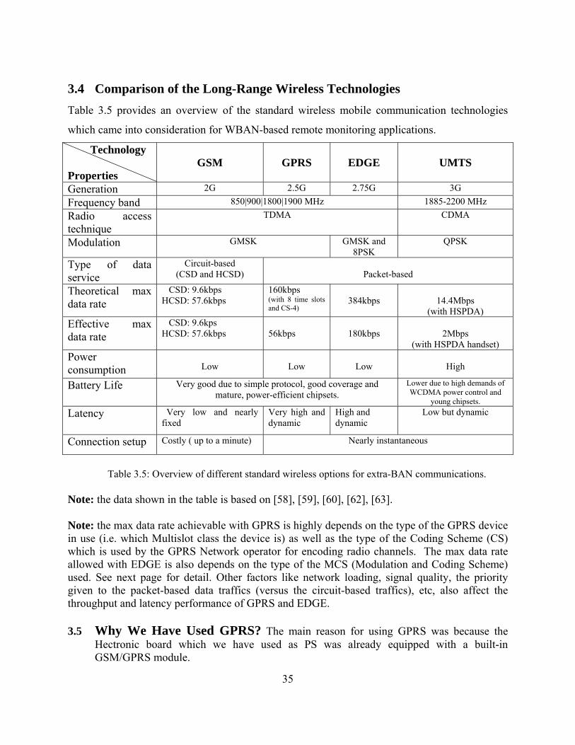
3.4 Comparison of the Long-Range Wireless Technologies Table 3.5 provides an overview of the standard wireless mobile communication technologies
which came into consideration for WBAN-based remote monitoring applications.
Technology GSM GPRS EDGE UMTS Properties Generation 2G 2.5G 2.75G 3G Frequency band 850|900|1800|1900 MHz 1885-2200 MHz Radio access technique
TDMA CDMA
Modulation GMSK GMSK and 8PSK
QPSK
Type of data service
Circuit-based (CSD and HCSD) Packet-based
Theoretical max data rate
CSD: 9.6kbps 160kbps HCSD: 57.6kbps 384kbps 14.4Mbps (with 8 time slots
and CS-4) (with HSPDA) Effective max data rate
CSD: 9.6kps HCSD: 57.6kbps 56kbps 180kbps 2Mbps (with HSPDA handset)
Power consumption
Low Low Low High
Battery Life Very good due to simple protocol, good coverage and mature, power-efficient chipsets.
Lower due to high demands of WCDMA power control and
young chipsets.Latency Very low and nearly
fixed Very high and dynamic
High and Low but dynamic dynamic
Connection setup Costly ( up to a minute) Nearly instantaneous
Table 3.5: Overview of different standard wireless options for extra-BAN communications.
Note: the data shown in the table is based on [58], [59], [60], [62], [63]. Note: the max data rate achievable with GPRS is highly depends on the type of the GPRS device in use (i.e. which Multislot class the device is) as well as the type of the Coding Scheme (CS) which is used by the GPRS Network operator for encoding radio channels. The max data rate allowed with EDGE is also depends on the type of the MCS (Modulation and Coding Scheme) used. See next page for detail. Other factors like network loading, signal quality, the priority given to the packet-based data traffics (versus the circuit-based traffics), etc, also affect the throughput and latency performance of GPRS and EDGE. 3.5 Why We Have Used GPRS? The main reason for using GPRS was because the
Hectronic board which we have used as PS was already equipped with a built-in GSM/GPRS module.
35

The following tables give extra details about the throughput (data rate) capabilities of the considered mobile phone technologies discussed in this chapter.
Technology Max Downlink Max Uplink Note
CSD 9.6kbps 9.6kbps 1+1
HSCSD 28.8kbps 14.4 kbps 2+1
HSCSD 43.2kbps 14.4 kbps 3+1
GPRS 80kbps 20.0 kbps 4+1 (Class 8 & 10 and CS-4)
GPRS 60kbps 40.0 kbps 3+2 (Class 10 and CS-4)
EGPRS (EDGE) 236.8kbps 59.2 kbps 4+1 (Class 8, 10 and MCS-9)
EGPRS (EDGE) 177.6kbps 118.4kbps 3+2 (Class 10 and MCS-9)
UMTS 384kbps 384kbps W-CDMA R99
UMTS 14.4Mbps 384kbps W-CDMA HSDPA
UMTS 14.4Mbps 5.76Mbps W-CDMA HSUPA
36
UMTS 42Mbps 22Mbps W-CDMA HSPA+
Table 3.6: Throughput comparison of different cellular mobile technologies Where: • Downlink is the throughput from the base station to the user handset or computer. • Uplink is the throughput from the user handset or computer to the base station. • X + Y expression in the “Note” column means X number of time slots in downlink and Y
number of time slots in uplink. For example, 3+2 means 3 time slots in downlink and 2 time slots in uplink. A GPRS Multislot Class-10 device can be configured either as 3+2 or as 4+1.
Table 3.7: The coding schemes used in GPRS
Coding scheme
Speed (kbps /slot)
CS-1 8.0
CS-2 12.0
CS-3 14.4
CS-4 20.0
Speed Modulation Coding and modulation (kbps/slot) scheme (MCS)
MCS-1 8.80 GMSK
MCS-2 11.2 GMSK
MCS-3 14.8 GMSK
MCS-4 17.6 GMSK
MCS-5 22.4 8-PSK
MCS-6 29.6 8-PSK
MCS-7 44.8 8-PSK
MCS-8 54.4 8-PSK
MCS-9 59.2 8-PSK
Table 3.8: The modulation and coding schemes used in EDGE

Chapter 1 - Details of the Proposed WBAN Prototype System
4.1 System Components The proposed WBAN system consists of the following key elements:
• A number of ZigBee-enabled wireless sensor nodes (SNs)
- One node configured as ZigBee coordinator device (which we call it “ZNC”
short for ZigBee Network Coordinator) and is attached to the PS board.
- A number of sensor nodes configured as ZigBee end-devices, each featuring a
motion sensor (tri-axial accelerometer) and a temperature sensor
• Personal Server(PS)
- The PS is a Linux-based, single-board minicomputer equipped with:
- A GPS receiver module
- A built-in GSM/GPRS module
- A ZigBee device (the ZNC).
• Remote Monitoring Server (RMS)
- The RMS is based on a Linux-powered internet-enabled PC
Figure 4.1: Schematic illustration of the proposed WBAN system
37

4.2 Sensor Node (SN) - Hardware Platform
4.2.1 Sensing Unit
Two types of sensors have been integrated into each sensor node platform:
• Motion sensor (3-axis accelerometer )
• Temperature sensor ( NTC Thermistor)
As motion sensor, the MMA7260 accelerometer module from Feescale Semiconductor [64]
is used, which is a low-cost capacitive Micromachined Accelerometer featuring signal
conditioning, 1-pole low pass filter, temperature compensation and g-Select that allows for the
selection among 4 different sensitivities. It also supports Sleep Mode that makes it ideal for
battery powered electronics. Other features include:
MMA7260 Accelerometer Features
• Selectable Sensitivity (1.5g/2g/4g/6g)
• Low Current Consumption: 500 µA
• Sleep Mode: 3 µA
• Low Voltage Operation: 2.2 V – 3.6 V
• 6mm x 6mm x 1.45mm QFN
• High Sensitivity (800 mV/g @ 1.5g)
• Fast Turn-On Time
• Low Cost Figure 4.2: Simple module evaluation using the EZ430 connected to MMA7260 accelerometer
module. For evaluation purposes, MMA7260 evaluation board is used as shown in the figure 4.2
The temperature sensor is based on the idea of Negative Temperature Coefficient (NTC),
which is basically a resistor that changes its resistance depending on the temperature.
The NTC Thermistor was implemented using a version of Wheatstone bridge. The
implementation detail is reported in [29].
38

39
4.2.2 Processing Unit
The microcontroller used for the WBAN sensor nodes is MSP430F2274 from Texas Instruments
[65]. The key technical specification of this microcontroller is provided in the table below. For
more detail information, interested reader is invited to consult the data sheet of the
MSP430F2274, which is available from [66]. And, the detail on how this microcontroller is
integrated into the PCB (Printed Circuit Board) of the prototype sensor node is reported in [29].
Table 4.1 TI MSP430F2274 Technical Specifications and features
Frequency 16 MHz
Architecture 16-Bit RISC Architecture, 62.5 ns Instruction Cycle Time
Flash 32 KB
RAM 1 KB
GPIO 32
Supply Voltage Range 1.8 to 3.6V
Power Consumption Ultralow-Power Consumption
Active Mode: 270 µA at 1 MHz2.2
Standby Mode: 0.7 µA
Off Mode (RAM Retention): 0.1 µA
Wakeup time Ultrafast Wake-Up From Standby Mode in Less Than 1 µs
ADC 10-Bit SAR
Other Integrated Peripherals 2 Operational Amplifiers
Interface USCI (UART/LIN/IrDA/SPI and I2C/SPI)
Timers 1 Watchdog/Interval, 2 16-bit (3CCR)

4.2.3 ZigBee Radio Module
40
ntroller (in our case TI MSP430
liant TI
•
Coordinator, Rou
and robust IEEE 802.15.4-compliant
• Powe
r wireless sensor networks
igure 4.3: Connecting TI CC2480 ZigBee module to the TI MSP430 Microcontroller through SPI
As ZigBee module, the Texas Instruments’ CC2480 chipcon is used which contains three
important components: 1) a ZigBee processor called “Z-Accel”, 2) a ZigBee stack called “Z-
Stack”, and 3) an IEEE 802.15.4-based radio transceiver which operates in unlicensed 2.4GHz
ISM frequency band. Z-Accel is a cost-effective, low power ZigBee Processor that provides full
ZigBee functionality. Z-Accel is a solution where TI’s ZigBee stack, Z-Stack, runs on a ZigBee
Processor and the application runs on an external microco
microcontroller) [67] , as shown in the figure.
Key Features of CC2480 (as described in [ 67] )
• Simple integration of ZigBee into any design
• Running the mature and stable ZigBee 2006 comp
Z-Stack
interface to any microcontroller running the application SPI or UART
• Simple API and full ZigBee API supported
• Can implement any type of ZigBee device: ter or End Device
2.4 GHz DSSS RF transceiver
• Automatically enters low power mode (<0.5 uA) in idle periods when configured as End Device
TI CC2480
• Radio
• Fully integrated
• Excellent receiver sensitivity and best in class robustness to interferers
r Supply Application Processor
(TI MSP430) • Low powe
• Set-top boxes and remote controls
• Automated Meter Reading
F
interface. Adapted from [67]
IEEE 802.15.4 radio
ZigBee Stack
(Z-Stack)
SPI Driver SPI Driver
Application
Z-Stack API
SPI

4.2.4 Power Supply Unit
To power the sensor board and all its components (including the microcontroller, ZigBee radio
transceiver, temperature sensor and accelerometer, and other circuitry) a 3V coin-cell lithium
battery is used with a nominal 190mAh.
4.2.5 Storage/Memory Unit
To simplify the design and reduce cost, the current prototype does not use external memory unit.
However, the TI MSP430 microprocessor itself has on-chip RAM memory (1Kbyte) and
32Kbyte on-chip FLASH memory.
4.3 Sensor Node (SN) - Software Platform
4.3.1 Custom Firmware
A custom-made, assembly-based firmware was developed for the ZigBee sensor prototypes. The
firmware was written in assembler in order to fully optimize the memory usage and implement
the application in a small and low cost microcontroller. This firmware manages the gathering and
processing of sensor data as well as interfacing with the ZigBee module (TI CC2480).
Due to the limited (1KByte) RAM on the microcontroller, the sensor-nodes have limited
buffering capacities. A total of 752 bytes was used for data buffering together with an additional
144 byte temporary RAM segment. Using a 3-axis accelerometer together with temperature
sensors this means that about 200 samples per axis can be buffered before it must be sent. In a
relatively low data rate application this buffer is adequate, but if more data is to be read by
sensors an additional external RAM or a more advanced microcontroller should be used. This
means that careful considerations regarding amount of data expected should be made before the
type of microcontroller is chosen. The total memory usage of the firmware is 6.7KByte of flash
memory. This means that only about 20% of the microcontroller’s total 32KB memory has been
used up. Further detail about the firmware controlling the sensor nodes is reported in [29].
41

4.4 Personal Server (PS) - Hardware Platform
4.4.1 Processing Unit
The microcontroller on the PS (Hectronic H6039) board is ATMEL AT91RM9200, which is a
complete system-on-chip built around the ARM920T ARM Thumb processor. This processor is
powerful enough to enable computation-extensive applications that require maximum
functionality at minimum power consumption and lowest cost [68]. The key features of the
microcontroller are described below:
42
ly during the development of the
pro
n size, lightweight, and power-efficient, so that it
an easily be worn or attached to user’s body.
Key Features of AT91RM9200 • Incorporates the ARM920T™ ARM® Thumb® Processor
– 200 MIPS at 180 MHz, Memory Management Unit (MMU)
– 16-KByte Data Cache, 16-KByte Instruction Cache, Write Buffer
• Low Power: On VDDCORE 24.4 mA in Normal Mode, 520 μA in Standby Mode
• Additional Embedded Memories
– 16K Bytes of SRAM and 128K Bytes of ROM
• Four Universal Synchronous/Asynchronous Receiver/Transmitters (USART)
– Hardware Handshaking
– RS485 Support, IrDA® Up To 115 Kbps
– Full Modem Control Lines on USART1
Figure 4.5: The Microcontroller on the PS board
4.4.2 Power Supply
The Hectronic H6039 board, which we have used as Personal Server (PS), was originally
designed specifically for automotive applications, such as remotely monitoring and controlling
vehicles. Because of that, it was assumed a car power supply with a 24V DC output will be used
to power the board. However, this type of board is used on
totype system, but not intended to be used for serious use.
In the beginning of the project, a representative of the manufactoring company of the board
(i.e., Hectronic AB [1]), has mentioned that they will develop a new board specifically for
WBAN applications, which will be very small i
c

Figure 4.6: The Hectronic H6039 board which is used as Personal Server (PS)
Current Consumption
According to our measurements, the average current consumption of the Hectronic board (model
h6039, Rev 1.2) is about 45mA during normal operation, and will rise to 55mA when the GPS
module is connected. And, when making a voice call through the GSM module, the current
consumption will rise to 80mA, i.e. the board will consume 25mA more current. And when the
ZigBee module (the ZNC) is connected, it will consume extra 10mA. Hence, the total current
consumption of the board is around 90mA, when the Linux is running, GPS and ZigBee modules
are connected and a voice call is placed.
4.4.3 Storage/Memory Unit
The PS board (Hectronic H6039 board) has a built-in 32MByte SDRAM (Synchronous Dynamic
Random Access Memory) and a 16MByte persistent FLASH memory. The RAM is used during
normal operation to host the boot loader (U-Boot), the Linux kernel, the root file system with all
the programs and utilities (BusyBox), user applications and user data (in our case GPS messages
and the data from all WBAN sensor nodes). The FLASH memory is used as a persistent storage
where all of the aforementioned items will be kept during power-down mode.
4.4.4 The Built-in GSM/GPRS module
43

To enable the communications between the WBAN and the Remote Monitoring Server (RMS)
which sits somewhere on the Internet, a GSM/GPRS modem is used. The modem is integrated
into a GE864-QUAD module manufactured by Telit [69], which is built into the PS board. The
detail hardware technical information can be found in [70]. Some of the features of the GE864-
QUAD are listed below:
GE864-QUAD Features: • Telit Unified AT Command Set • Quad Band GPRS • GPRS Class 10 • SIM Access Profile • Extended RF Sensitivity
Figure 4.7: Telit GE864-QUAD GSM/GPRS module
4.4.5 The Attached GPS Receiver Module
The GPS receiver attached to the PS board is called GPS-310FA which is manufactured by RF
Solutions Ltd. [71]. The GPS-310FA is a small, single-board, 16 parallel-channels GPS receiver.
GPS-310FA FEATURES Receiver Type: 16 parallel channel, L1 C/A code
Accuracy:
Position: 5m CEP
Velocity: 0.1m/sec
1PPS Timing: +/-1us
Startup Time: < 10sec hot start Figure 4.8: GPS-310FA GPS receiver module < 35sec warm start
< 60 sec cold start
Signal Reacquisition: 1s
Sensitivity: -140dBm acquisition
-155dBm tracking
Update Rate: 1Hz
Protocol:
NMEA-0183 V3.01,
GPGGA, GPGLL, GPGSA, GPGSV, GPRMC, GPVTG, GPZDA
4800 baud, 8, N, 1
44

4.4.6 The Attached ZigBee Network Coordinator Device (ZNC)
In order for the PS to be able to communicate with the ZigBee-enabled WBAN sensor nodes and
collect their data, a ZigBee-enabled device has been attached to the PS board. This device is
configured as a “ZigBee Coordinator”; meaning that it is responsible to initiate a ZigBee wireless
network and let the WBAN sensor nodes (i.e., the ZigBee end devices) to join the network and
then coordinate between them during normal operation. Therefore, we call it ZNC (ZigBee
Network Coordinator). Just like the end-device wireless sensor nodes described in section 4.3,
the radio transceiver of the ZNC device operates in the unlicensed 2.4GHz ISM frequency band.
Beside being the coordinator, the ZNC has other roles in the ZigBee network. It acts as a
“gateway” to the ZigBee Network by allowing traffics from the extrernal networks to enter the
ZigBee network and vice versa. It also acts as a “sink node” by collecting data from all other
sensor nodes in the ZigBee network. Furthermore, the ZNC can issue control/configuration
commands to the sensor nodes in the ZigBee network for purposes like reconfiguing the network
or the sampling rates of the sensors, restarting sensor nodes and so on.
45

4.5 Personal Server (PS) - Software Platform
4.5.1 Embedded Linux Operating System
The Personal Server (i.e., the Hectronic H6039 board) running a special distribution of
embedded Linux OS called Helix1. Helix uses Linux kernel as a base to build custom embedded
Linux system targeting Hectronic-made hardware platforms. Actually, Helix is not an Operating
System in itself. Rather, it is a set of tools which assist in building Linux systems that best suit
the embedded electronic boards made by Hectronic AB, as illustrated in the figure below: Figure 4.10: The architecture of Helix 1 The name “Helix” is derived from Hectronic (He), Linux (li) and "cross compiling" (x).
46

4.5.2 Embedded Application Software
An embedded, multi-threaded, C-based application program has been developed for the Personal
Server. The program was written on a development host (a PC running Ubuntu Linux), then
cross-compiled using an appropriate toolchain and downloaded to the target board via serial
cable. The following highlights some of the tasks the PS application can perform:
• Communications with the GPS receiver
• Collecting and processing GPS messages (NMEA sentences)
• Communications with the GSM/GPRS modem
• Establishing and maintaining GPRS connections
• Communications with the WBAN sensor nodes through the ZNC.
• Collecting, processing and time-stamping the data messages generated by the sensors
• Compressing and encrypting the data messages collected from the GPS receiver and the
WBAN sensor nodes and transmitting them securely and wirelessly through GSM/GPRS
network to the Remote Monitoring Server (RMS) on the Internet.
Chapter 6 provides further details about the PS application and its functionalities,
Figure 4.11: A block diagram describing the PS application
47

Chapter 2 - GPS Technology
5.1 Introduction to GPS technology
5.1.1 What is GPS?
The Global Positioning System, or GPS for short, is a precise, satellite-based navigation and
positioning system originally developed for military use by the US Department of Defense which
later made available to civilian uses. GPS uses a constellation of 24 to 32 navigation satellites
(space vehicles) that systematically move in Medium Earth Orbits [72]. Each satellite continually
transmits specially-coded, precise radio-wave signals containing timing and positioning
information, which enable GPS receivers to determine the time and their current location.
5.1.2 The GPS Segments
GPS consists of three major segments (see figure 5.1): Space Segment, Control Segment and
User Segment as described below:
Space Segment (SS)
The space segment comprises the navigation satellites (also called Space Vehicles) which are
systematically orbiting around Earth and continually transmitting precisely timed, coded signals
to the GPS receivers on Earth. A typical satellite or Space Vehicle (SV) consists of 2 solar panels
(for scavenging solar energy and powering the SV), a main body, and a number of atomic clocks
(cesium and rubidium) which provide very precise timing information.
Control Segment (CS)
The control segment comprises a network of tracking and monitoring stations located around the
world. It consists of two parts: a Master Control Station, and a number of Monitoring Stations.
The Master Control Station is located in Colorado, USA [73]. The monitoring stations measure
signals from the SVs which are incorporated into orbital models for each satellite. The models
compute precise orbital data called “ephemeris” and SV clock corrections for each satellite. The
Master Control Station uploads ephemeris and clock data to the SVs. The SVs then send subsets
of the orbital (ephemeris) data to the GPS receivers over radio signals [73].
48

User Segment (US)
This segment comprises the GPS receivers and the user community. GPS receivers acquire time
coded radio signals from the SVs to determine their location and derive the speed and direction
of movements from the location information. A typical GPS receiver consists of the following
components:
• Antenna: to collect GPS radio signals
• Receiver-processor: to compute (trilaterates) a position which could be 2D (only
latitude and longitude) or 3D (latitude, longitude, and altitude)
• Firmware: software that controls the GPS receiver and user interface (if any)
• Storage/Memory: stores position and possibly attribute data
• Display (if any): for showing position and time information to the user.
GPS receivers can be used for different purposes including:
• Positioning - determining the current location.
• Navigation - determining distance and direction to a position (waypoint)
• Data logging - recording characteristics about a position
• Timing - determining specific time period of an event
Figure 5.1: The three segments of GPS
49

5.1.3 How GPS Works?
How GPS receivers calculate their position?
Signals from navigation satellites include:
• Binary timed code
• Almanac with position of satellite
• Accurate time ( from atomic clocks)
With this information a GPS receiver can calculate the time the coded signal takes to get from
the satellite to the receiver. Then it uses a technique called “trilateration” which means the
receiver collects signals from at least 3 satellites to compute its location as following:
Trilateration
• Time for signal to travel from satellite to GPS receiver is calculated
• The distance from 3 or more satellites is calculated from that time.
• Receiver calculates its position on earth based on these 3 distances.
If the distance from three satellites is known, the point of intersection between the three distances
is the receiver’s location.
How GPS receivers calculate Time?
• Almanac tells receiver exactly where each satellite is located.
• Receiver acquires signals from each visible satellite
• Coded signal – receiver knows when signal left the satellite
• Difference in coded signal between time it left satellite and reached the unit is
• Exact time for signal to reach receiver can be calculated for each satellite in view
How GPS receivers calculate Distance?
• Timed coded signal travels at speed of light (which is known)
• Offset in timed coded signal from satellite to receiver provides time
• Distance from receiver to satellite is calculated by (time offset X speed of light)
• Distance to a minimum of 3 satellites is needed to determine position.
50

5.2 The NMEA Standard
5.2.1 What is NMEA?
NMEA is a standard protocol defined by the U.S.-based National Marine Electronics Association
(NMEA) for communication between marine electronic devices such as echo sounder,
sonars, navigation instruments, gyrocompass, autopilot, and GPS receivers.
NMEA defined two different standards; one is called NMEA 0183 and the other is NMEA
2000. Most of the GPS receivers support NMEA 0183. The NMEA 0183 standard uses a
simple ASCII, serial communications protocol that defines how data is transmitted in a
"sentence" from a "talker" to a "listener", for example, from a GPS unit to a computer or mobile
phone connected via serial port. NMEA 0183 specified the serial configuration as shown in the
table: Baud rate 4800 bps
51
Data bits 8
Parity None
Stop bits 1 (or more)
Handshake None
The NMEA 0183 standard has also defined the contents of each sentence (message) type so that
all listeners can parse messages accurately.
5.2.2 Specification of the NMEA Messages
The following describes the NMEA messages:
• Each NMEA message starts with a dollar sign '$'
• The next five characters identify the talker (two characters, e.g. GP for GPS) and the type
of message (three characters, e.g. RMC).
• The rest of the fields are comma separated
• The first character that immediately follows the last data field character is an asterisk '*'
• There is a two-digit hexadecimal number representing the checksum which comes
immediately after the asterisk. The checksum is the exclusive OR of all characters
between the '$' and '*'.
• Each NMEA message or sentence ends with <CR><LF>

5.2.3 Parsing NMEA Stream
A GPS receiver which uses NMEA 0183 protocol generates data stream consisting of a series of "sentences" delimited by a newline character. Each sentence starts with a single dollar sign ‘$’ followed by five character identifier. The NMEA 0183 standard has defined many different sentences, but only a few of them are usually supported by a typical GPS receiver. The most useful sentences include:
• $GPGGA - Global Positioning System Fix Data • $GPGLL - Geographic Position, Latitude/Longitude • $GPGSV - GPS Satellites in View • $GPRMC - Recommended Minimum Specific GPS/TRANSIT Data • $GPVTG – Course Over Ground and Ground Speed • $GPZDA - UTC Date/Time and Local Time Zone Offset
Out of the above NMEA sentences, $GPRMC is the most widely used, since it contains most of the interesting information, like position fix data (latitude and longitude), time in UTC (Universal Coordinator Time), as well as other derivates like speed. The general format of $GPRMC is given below along with an example.
Format: $GPRMC,<1>,<2>,<3>,<4>,<5>,<6>,<7>,<8>,<9>,<10>,<11>,<12>*<13><CR><LF>
Example: $GPRMC,104549.04,A,2447.2038,N,12100.4990,E,016.0,221.0,250109,003.3,W,A*22<CR><LF> Filed Example Description 1 104549.04 UTC time in hhmmss.ss format, 000000.00 ~ 235959.992 A Status, ‘V’ = navigation receiver warning, ‘A’ = valid position3 2447.2038 Latitude in dddmm.mmmm format 4 N Latitude hemisphere indicator, ‘N’ = North, ‘S’ = South
12100.4990 5 Longitude in dddmm.mmmm format 6 E Longitude hemisphere indicator, 'E' = East, 'W' = West
016.0 Speed over ground, 000.0 ~ 999.9 knots 7 221.0 Course over ground, 000.0 ~ 359.9 degrees 8 250109 UTC date of position fix, ddmmyy format 9 003.3 Magnetic variation, 000.0 ~ 180.0 degrees 10
Magnetic variation direction, ‘E’ = East, ‘W’ = West 11 W 12 A Mode indicator
‘N’ = Data invalid ‘A’ = Autonomous ‘D’ = Differential ‘E’ = Estimated
13 22 Checksum Note: The checksum field starts with a ‘*’ and consists of 2 characters representing a hex number. The checksum is the exclusive OR of all characters between ‘$’ and ‘*’.
52

5.3 Specification of the GPS Receiver used in the project The GPS receiver we have used in the project is called “GPS-310FA” which is manufactured by
RF Solutions Ltd [61]. The receiver supports NMEA 0183 protocol and produces six types of
NMEA sentences, GGA, RMC, GLL, GSV, VTG, and ZDA. See chapter 4, section 4.5.5 for the
technical specification of the receiver. And, for extra detail consult GPS-310FA data sheet [61].
5.4 Using GPS Time for Time Synchronization As mentioned earlier, the GPS navigation satellites or Space Vehicles utilize atomic clocks
(cesium and rubidium) which give very accurate time. This accurate time can be used as a global
reference time to synchronize local system time (which is typically from crystal oscillator clock
that is prone to frequent drifts). For example, we can use the UTC time obtained from a GPS
receiver to calibrate the hardware clock on the Personal Server’s board or to time-stamp WBAN
sensor messages immediately after reception at the PS. In the later case, a precise time to time-
stamp the messages can be calculated using a simple equation as shown below:
Tstamp = Tgps + (Tsys2 – Tsys1)
Where: Tstamp is the time which we want to use to time-stamp a sensor message. Tgps is the UTC time which is obtained from the GPS receiver Tsys1 is the system time when the first NMEA message containing Tgps has been received Tsys2 is the system time when a sensor message (to be time stamped) has been received
53

Chapter 3 - Design and Implementation of the Personal Server
Application Software
6.1 Overview In this chapter we will discuss the design and implementation of the application software which
runs on the Personal Server (PS). We will first describe the required functionalities of the
application (i.e., the tasks that the PS application should perform), and then discuss how we have
designed and implemented the application so that to meet the requirements. In this chapter, we
will also provide general information about serial-port programming in Linux, modem
communications using AT commands, GPRS communications using AT commands, and Point-
to-Point Protocol (PPP).
6.2 The Required Functionalities of the Personal Server Application Before designing the application, we have to first decide what the application should do, that is
to specify the requirements for the application, and then take approaches to find a proper solution
which fulfills the requirements. After studying the initial system requirements, it was decided
that the application should, in general, be responsible for the following tasks:
• Communications with the devices on the PS board
• Data Collection
• Data Processing & Manipulations
• Data Buffering
• Data Compression
• Data Encryption
• Data Communication
The above tasks are briefly described in the following section.
54

Communications with the Devices on the PS board
One of the tasks of the PS application is to communicate with the devices on the PS board. There
are three devices on the board which are connected via serial interfaces: 1) ZigBee Network
Coordinator (ZNC) device, 2) GPS receiver module, and 3) GSM/GPRS modem. The ZNC acts
as a “sink” node and a gateway to the ZigBee-based wireless sensor network. So, to be able to
read data from the sensor nodes and send configuration/control commands to them, the PS
application has to communicate with the ZNC. The GSM/GPRS modem acts as a gateway to the
Internet, and is mainly used to transfer WBAN data (i.e. the data from the GPS and the ZigBee
sensor nodes) to the RMS.
Figure 6.1 depicts the scenario where the ZNC and GPS forward data through serial
interfaces to the microcontroller on the PS board, which the PS application has to collect,
process, and communicate them with the RMS via the GSM/GPRS modem.
55
Figure 6.1: A flowchart illustrating the PS application functionalities
Serial interface
GSM/GPRS
MODEM
Data Collection
Data Processing & Manipulations
Data Compression & Encryption
Data Communications
GPS module
Serial interface
ZigBee network
Sensor 1 Sensor N
ZigBee radio
ZNC
The functionalities
of the embedded
application running
on the PS

Data Collection
This task is involved with collecting data from the WBAN sensor nodes and the GPS receiver.
The sensor nodes encapsulate their data into ZigBee messages (or frames) and forward the
messages through the ZigBee network to the ZNC which acts like a “sink” node. The ZNC
forwards the messages further to the PS via serial interface (UART). The GPS receiver generates
NMEA messages (or sentences) containing timing and position information, and sends them to
the microcontroller on the PS board via serial port. Thus, the PS application has to first connect
to the input devices (i.e., the ZNC and GPS) via serial ports, and then read data from them.
Data Processing and Manipulations
The program has to process the data which has been collected in the Data Collection phase. This
task includes the following sub-tasks:
- Message filtering & feature extraction: e.g., filtering the GPS NMEA messages and
collecting only those with interesting information (like position fix and timing info),
filtering ZigBee sensor messages and extracting desired features, etc.
- Conversion: for instance, converting GPS NMEA messages from ASCII to Binary so
that to shrink their size and consequently saving storage space (memory), network
bandwidth, and cost (since in GPRS, we have to pay for the amount of data we send
over a GPRS connection. Thus, the less we send, the less we pay! )
- Formatting: formatting the ZigBee and GPS messages according to the specification
of our data model.
- Time Stamping: using the system and/or GPS time to timestamp the ZigBee sensor
messages, e.g. for purposes like Time Synchronization— identifying the time when a
certain event has occurred or a message has received.
56

Data Buffering
Since we are using GPRS to transfer WBAN data from the PS to the RMS, we should not
assume that the communication link is always up and the data can always reach the intended
destination. But instead, we must always count for events like unexpected connection timeouts
and disconnections due to factors like out-of-coverage-area or out-of-radio-reach, poor signal
reception, noisy environment, network congestions, etc. Thus, we need a way to assure data
integrity. A common way to cope with connection instability problem is to buffer data locally
and (re)transmit it whenever the communication link is available again.
Data Compression
Another task of the PS application program is to compress the data messages collected from the
WBAN sensor nodes and the GPS receiver, so that to reduce their size and consequently reduce
the required network bandwidth, cost, and transfer time.
Data Encryption
Since the sensor data collected from the body of a user will be sent over “public” and “insecure”
networks like the Internet, security can be a big concern, especially for security-sensitive
applications such as military and healthcare where protecting the privacy and confidentiality of
user’s information are crucial requirements. For example, threats like eavesdropping (e.g.
capturing data in transit using software tools like “Packet Sniffer” or “Protocol Analyser” for
network traffic analysis) can put confidentiality and privacy at risk.
Therefore, one of the tasks of the PS application program is to provide data transmition
security through encrypting the WBAN sensor messages before sending them through
GPRS/Internet to the RMS. Authentication should also be used so that the PS is sure that it
communicates with the right RMS and vice versa.
Data Communication
Data communication is one of the most important tasks of the PS application. This task is
involved with establishing and maintaining GPRS connections and transmitting the WBAN
sensors’ data (after it has been collected, properly processed and encrypted) to the intended
destination (i.e., the RMS which sits somewhere on the Internet).
57

After we have described the tasks that the application should perform, let’s now proceed to the
design phase.
6.3 Design Approaches Two approaches have been taken to design the Personal Server (PS) application: 1) Single-
threaded approach, and 2) Multi-threaded approach. We will discuss these two approaches in the
following sections and address the advantages and disadvantages associated with each of them.
6.3.1 Single-Threaded Approach
58
w:
configuration and initialization:
S and GPRS modules
• Read and process GPS data
sor data
PRS to the RMS.
his approach has the following advantages:
single execution thread which calls a series of
- need to
owever, it has the following drawbacks as well:
o tasks concurrently (simultaneously)
ts and
disconnections.
From the beginning, it was believed that a simple and single-threaded application would be able
to handle all of the tasks we have described earlier without problems. Based on this assumption,
a single-threaded application has been developed as described belo
• Do system
- Load configuration data
- Configure the serial ports
- Configure the ZigBee, GP
- Etc.
• Read and process ZigBee sen
• Encrypt and send the data through the G
T
- Easy to implement: we only have a
functions (each dedicated to perform a certain task) sequentially and repeatedly.
No concurrency issues: since we only have a single execution thread, there is no
bother with issues like deadlocks, starvation, race condition…etc.
H
- Inefficient solution: can’t perform tw
- Data integrity can’t be guaranteed: data get lost during timeou

59
6.3.2 Mu i-
It turned out efficient solution, since the
program was not able to perform two or more tasks simultaneously. For example, it has to wait
be completed before attempting to read new data, meaning
• A) messages.
emote internet host (i.e. the
Figure 6.2: The architecture of the multi-threaded PS application
threads) to implement multithreading, through using the
standard APIs de ), pthread_exit(),
pthread_attr_*, pthread_mutex_*, pthread_cond_*, etc.
lt Threaded Approach
that a single-threaded application cannot provide an
for the data transmission via GPRS to
that important data might get missed or delivered rather late. Furthermore, the data integrity was
not ensured with this approach as data might not be gathered during timeout and disconnections.
To overcome those problems, a multi-threaded application has been developed instead,
which consists of four different threads (see the figure):
• Main (Coordinator) Thread: the main thread performs general system configurations and
initializations as well as controlling and coordinating other threads.
• ZigBee Data Handler Thread: collects and processes the WBAN sensors’ data (which is
encapsulated into ZigBee messages) that arrive via the ZNC.
GPS Data Handler Thread: collects and processes the GPS data (NME
• GPRS or Data Uploader Thread: maintains GPRS connections, compress and encrypt the
ZigBee and GPS data messages and transmits them to the r
RMS).
We have used POSIX threads (P
fined in the pthread Library, such as pthread_create(

The following flowchart describes the multithreaded version of the PS application:
60
Figure 6.3: A flowchart describing the multithreaded Personal Server application

61
he Advantages and Disadvantages of Multithreading
he multithreaded approach has the following advantages:
Pros:
+ More than one task can be performed concurrently (simultaneously): do something
ul while waiting for something else. For example, read/process new data while
+
PRS).
this approach as data can be buffered during
Howev
ons:
- Requires sophisticated thread synchronization techniques
(We have used “mutex” and conditional variables to synchronize the threads)
ful!
etc
T
T
+ Efficient solution: better resource utilization
usef
waiting for data transfer to be completed.
+ Distinguish tasks of varying priority
Manage input from several devices: E.g., separate threads to handle communications
to different interfaces (GPS, ZigBee, and G
+ Data integrity can be ensured with
timeouts and disconnections.
er, it has the following pains and drawbacks as well:
C
- Difficult to implement
- Debugging is really pain
- Concurrency issues: deadlock, starvation, race condition...

62
.4 Communication with the Devices on the PS Board
Connecting to the Devices via Serial Ports
connected to the ARM
microcontroller via serial ports. The microcontroller has four UART interfaces (UART 0 – 3).
in Linux) is connected to the serial debug
es (containing position and timing information) and
forw
, “Everything is a file”, also holds true in Linux systems; which means
anything that is physically or logically attached to a Linux machine, and that the Linux kernel
em. For example, serial ports are defined as special
e programmer to get
to t
to-deal-with associated device files, but it still requires a programmer to put some efforts into
6
6.4.1
The devices attached to the Personal Server (PS) board are
The first UART (i.e., UART-0 or ttyS0 as defined
cable which is used to connect to the debugging console. The GSM/GPRS module is connected
via the second UART (UART-1, or ttyS1), while the ZigBee Network Coordinator (ZNC) device
is connected through the third UART (UART-2, or ttyS2). Finally, the fourth UART (ttyS3) is
connected to the GPS receiver module.
The ZNC device collects the data generated by the WBAN sensor nodes (the ZigBee end-
devices) and forwards them via serial interface (UART-2) to the PS. Similarly, the GPS receiver
device generates GPS NMEA messag
ards them to the PS via serial port (UART-3). The GSM/GPRS module can receive data
from the PS via serial interface (UART-1) and sends them via GSM/GPRS network to an
Internet host. Thus, the application controlling the PS must connect to the input devices (GPS
and ZNC) via serial ports in order to read data (NMEA and sensor messages) from them, and it
should connect to the GSM/GPRS module via serial port in order to send the collected data to the
remote server (RMS).
6.4.2 Serial Port Programming in Linux
The UNIX philosophy
can see, is represented as a file in the file syst
device files under /dev directory, like /dev/ttySn (where n= 0, 1, 2, 3…).
This feature, i.e. “Everything is a file”, makes Linux an ideal platform from a programmer’s
perspective. Since Linux removes or alleviates most of the difficulties associated with dealing
with a diverse range of hardware devices, which would otherwise required th
he low-level details of how to communicate with those hardware devices.
Though Linux simplified dealing with hardware devices, like serial ports, by defining easy-

63
.
rom it
when finished with
The above procedures are explained in the following:
1- In Linux, serial ports are associated with device files in the /dev directory, for example serial port
with /dev/ttyS1 and so on. To open a
rial port, simply open its associated device file using open() system call. For example, the
ws how to connect to a GSM/GPRS modem via serial port 2 (i.e.
configuring the devices (serial ports) according to the application needs and the specifications set
by the hardware manufacturer, before attempting to read from or write to them
To communicate with a hardware device connected via serial port, the following procedures
can be used:
1- Open the serial port
2- Configure the port
3- Write to it
4- Read f
5- Finally, close the port
Opening Serial Ports
1 (or COM1) is associated with /dev/ttyS0, COM2
se
following C code fragment sho
/dev/ttyS1):
#include <unistd.h> /* For the definition of open() system call */
int fd; /* file descriptor of the port*/
/* O_RDWR: means open the serial port’s device file for reading and writing
O_NCTTY: means we don’t want this program to be the “controlling terminal”
O_NDELAY: means we don’t want to be blocked until the other end of the serial connection gets online */
fd = open(“/dev/ttyS1” , O_RDWR | O_NCTTY | O_NDELAY);
if ( fd < 0)
printf(stderr, “Failed to open the port!\n”);
else
printf(“The port is now open and accessible via fd.\n”);
Note: For more details about open() function and all its options and flags, consult the manual
of the open(2) system call. page

2- Configuring Serial Ports T
64
he devices /dev/ttyS* are intended to hook up terminals to your Linux box, and are configured
from the device back to it,
r data transmission.
for this use after startup. This has to be kept in mind when programming communication with a
raw device. E.g. the ports are configured to echo characters sent
which normally has to be changed fo
All parameters can be configured from within a program. The configuration is stored in a
structure struct termios, which is defined in <asm/termbits.h>:
#define NCCS 19
struct termios {
tcflag_t c_iflag; /* input mode flags */
tcflag_t c_oflag; /* output mode flags */
tcflag_t c_cflag; /* control mode flags */
tcflag_t c_lflag; /* local mode flags */
cc_t c_line; /* line discipline */
cc_t c_cc[NCCS]; /* control characters */
};
his file all g definitions. The input mode flags in c_iflag handle all input
the cha e device can be processed before they
read with read()function. Similarly c_oflag handles the output
rocessing. c_cflag contains the settings for the port, as the baudrate, bits per character, stop
T also includes fla
processing, which means that racters sent from th
are
p
bits, etc.. The local mode flags stored in c_lflag determine if characters are echoed, signals are
sent to your program, etc. Finally the array c_cc defines the control characters for end of file,
stop, etc. Default values for the control characters are defined in <asm/termios.h>. The flags
are described in the manual page termios(3). The structure termios contains the c_line (line
discipline) element, which is not used in POSIX compliant systems.

65
- Writing Data to Serial Ports o send things to a serial port, first open the port in writing mode, configure it, and then use
rite() system call. For example, the following code snippet shows how to send a simple AT
ommand (more about AT commands in the later sections of this chapter) to the GSM/GPRS
h we have opened it earlier (see Opening Serial Ports)
3T
w
c
modem connected via /dev/ttyS1 whic int bytes_written;
/* suppose fd is the file descriptor for the GPRS serial port device file which is opened in writing mode */
bytes_written = write (fd, “AT\r”, 3);
if (bytes_written < 0 )
printf(stderr, “Failed to write 3 bytes of data\n”);
4- Reading Data from Serial Ports rial port, first open the port’s device file in read mode (using O_RDONLY or
figure it correctly, and then use read() system call
to read data (byte streams) from the port.
data (NMEA messages) from a GPS receiver
ad() function to read the GPS messages arrived at the
seri
To read data from a se
O_RDWR flag with open(2) system call) , con
For example, let’s assume we want to read
device which is connected to the serial port 4 (/dev/ttyS3) and display them on screen. Let’s
also assume that fdr is the file descriptor pointing to the /dev/ttyS3 device file which is
opened in read mode. Now, we can call re
al port’s input buffer, as shown below: char *NMEA_buff[255];
int n;
while( 1) /* loop forever */
{
n = read(fdr , NMEA_buff, 254);
NMEA_buff[n] = ‘\0’; /* Null-terminate the string */
printf(“%s \n”, NMEA_buff); /* print GPS NMEA messages*/
}

66
- Closing Serial Ports o close a serial port, simply close the device file associated with it using close() system call
nd any file streams connected to it using fclose() function. For example, to close a serial port
hose device file is opened and pointed to by a file descriptor fd, simply use close(fd).
ram
has to connect to UART-3 in order to be able to configure the GPS receiver (by sending binary
es from it.
connect to a GPS receiver via
/ttyS3).
• Configure the GPS serial port
system call to read data (byte streams) from it. (see Listing 6.1 )
vice: to send configuration commands to the GPS device,
For a
port, re
5T
a
w
6.4.3 Communication with the GPS Receiver
The GPS receiver module is attached to the PS board and connected to the ARM microcontroller
through UART serial port 4 (i.e., ttyS3 as defined in Linux). Thus, the PS application prog
messages/commands to it) and read NMEA messag
The following procedures describe how to communicate with a GPS receiver connected via
serial port:
• Connect to the GPS receiver device via serial port: To
serial port, use open() system call to open the serial port’s device file (in our case
/dev
• Read data (NMEA messages) from the GPS device: to read data from the GPS device via
serial port, we have to first open the serial port’s associated device file in read mode, and
then use read()
• Send commands to the GPS de
first open the port in writing mode and then use write() system call. Alternatively,
connect the device file with a regular file using fdopen() system call to make use of the
common file operation APIs, such as fprintf() function.
• Disconnect from the GPS device: To disconnect from the GPS, simply close the serial
port where it’s connected by closing the associated device file using close() system call
and any file streams connected to it using fclose() function.
ex mple, the following C code fragments illustrate how to open and configure the GPS serial
ad data (NMEA messages) from it.

Listing 6.1 a sample C code shows how to connect to a GPS via serial port and read data
(NMEA messages) from it.
#include <stdio.h> /* Standard input/output definitions */
#include <fcntl.h> /* File control definitions */
#include <termios.h> /* POSIX terminal control definitions */
#include <unistd.h> /* UNIX standard functions definitions */
struct termios settings;
int fdr; /* File Descriptor Read for the GPS serial port device file */
const char* gpsport= “/dev/ttyS3”; /* Suppose the GPS device is connected to the COM4 serial port */
printf("Opening %s port for reading…", gpsport);
/* O_RDONLY: open the GPS serial port so that we read from,
O_NOCTTY: we don’t want this program to be a controlling terminal.
O_NDELAY: also we don’t wish to wait for the other party of the serial connection until it connects */
if((fdr = open(gpsport, O_RDONLY | O_NOCTTY | O_NDELAY)) == -1) {
printf(“failed!”);
}
printf(“succeed.”);
/* Blocking the calling process (or thread) until something is arrived at the serial-port’s input buffer, or
timeout or error events occur */
fcntl(fdr, F_SETFL, 0);
/* For non-blocking call use this one instead */
fcntl(fdr, F_SETFL, FNDELAY);
/* get the current serial port settings */
tcgetattr(fdr, &settings);
/* CLOCAL: local connection, no modem control
CREAD: we want this program to be the receiving side of the serial connection
ICANON: enable canonical (processed) input
ECHO | ECHOE | ISIG: disable all echo functionality, and don't send signals to the calling program
*/
67

settings.c_cflag |= (CLOCAL | CREAD);
settings.c_lflag |= ICANON;
settings.c_lflag &= ~(ECHO | ECHOE | ISIG);
/* Set baud rate to 4800, character size to 8, no parity and 1 stop bit (8N1)
as defined by the NMEA 0183 standard */
/* Set baud rate to 4800bps. Note: a range of standard baud rates are defined in <asm/termbits.h>
Header file which is included by <termios.h> */
cfsetispeed(&settings, B4800);
cfsetospeed(&settings, B4800);
/* Set character size to 8, no parity, and use one stop bit (8N1) */
settings.c_cflag &= ~PARENB; /* Mask the parity enabled bits */
settings.c_cflag &= ~CSTOPB; /* Mask the stop bit, B means 2 bits, but we only want 1 bit */
settings.c_cflag &= ~CSIZE; /* Mask the character size bits */
settings.c_cflag |= CS8; /* Select 8 data bits*/
/* Disable hardware flow control, since we don’t have real modem on this port, only Tx , Rx and power lines */
settings.c_cflag &= ~CRTSCTS;
/* Disable software flow control */
settings.c_iflag &= ~(IXON | IXOFF | IXANY);
/* Clean the GPS serial line and save the settings we did */
cflush(fdr, TCIFLUSH); t
tcsetattr(fdr, TCSANOW, & settings);
/* After opening and configuring the GPS serial port, we can now read the NMEA messages from
the GPS receiver through the serial port using read() system call and display them on the screen (for example) */
char *NMEA_buff[255];
int n;
while( 1) /* loop forever */
{
n = read(fdr , NMEA_buff, 254);
NMEA_buff[n] = ‘\0’; /* Null-terminate the string so that we printf() */
printf(“%s \n”, NMEA_buff); /* print GPS NMEA messages*/
}
68

6.4.4 Communication with the ZigBee Network Coordinator Device
69
the PS board and connected to the
M microcontroller through UART serial port 3 (ttyS2). However, this port only has an Rx
line and a power line, but not Tx line. This means that we are only able to read things from the
ZigBee device but not to send things to it. To overcome this problem, it was decided to share the
Tx line of the UART-3 (i.e., the GPS serial port) between the GPS device and the ZigBee device.
By doing so, we could write things (configuration commands) to the ZigBee device via the Tx
line of the GPS serial port.
6.4.5 Communication with the GSM/GPRS Modem
The PS communicates with the GSM/GPRS modem via serial port using the standard modem
communication protocol known as Hayes AT Commands. The GSM/GPRS modem is connected
to the ARM microcontroller via UART0 serial port (i.e., ttyS1). This port has all the necessary
lines (Rx, Tx, DCD, DTR, and DSR) connected which a real modem needs. The ATMEL
AT61RM920 ARM microcontroller—the CPU of the PS board— supports 4 UART serial ports
(port 0 through port 3), out of which only port 1 can be used to interface with a real modem
device, that is why the GSM/GPRS modem is connected via this port.
Just like the GPS device, we can connect to the GSM/GPRS modem by opening the device
file associated with the serial port where the modem is connected. Once we have connected to
the GSM/GPRS modem via serial interface, we can then use the standard modem communication
protocol (i.e., Hayes AT commands) to talk to the modem as described in the next section
“Modem Communications using AT Commands”.
The ZigBee Network Coordinator (ZNC) device is attached to
AR

70
6.5 Modem Communications Using AT Commands
uch as dialing a certain number to setup a connection. A typical
GSM/GPRS modem has two modes: data mode and command mode. While in data mode, the
odulation). The modem can
depending on the type of
the
Possible Response(s)
6.5.1 What is Modem?
Modem (short for modulator-demodulator) is a device that modulates an analog carrier signal to
encode digital information, and also demodulates such a carrier signal to decode the transmitted
information[74]. Modems are designed to convert digital or binary data (i.e., streams of ones and
zeros) to/from analogue or digital signals which can be transmitted over a transmission media
such as telephone lines, radio interface, etc. Besides data conversion, (smart) modems also
provide additional services, s
modem is used mainly for data conversion (i.e., modulation and dem
receive, interpret, and respond to AT commands while in command mode.
6.5.2 What are AT Commands?
AT commands are standard commands for communicating with and setting up modems. A
typical modem supports a subset of AT commands, consult your modem’s manual for a list of
commands your modem can understand. An AT command starts with AT or at (from attention,
for getting the modem's attention) followed by one or more characters,
command, and ends with a CR (carriage return) character. When a modem receives an AT
command, it will process/interpret it and respond with one of several textual response messages
depending on the command. The following table provides a few examples of AT commands
supported by a typical GSM/GPRS modem: AT Command Meaning Example
ATD Dial a specified
number
ATD +46762003959 <cr> //make a voice
ATD*99# <cr> //make a data (CSD) call
NO CARRIER
CONNECT
ATA wer
incoming call
ATA<cr> CONNECT
ERROR
Ans
ATH hang-up the
MODEM
ATH<cr> OK
ATZ Resets the
MODEM
ATZ<cr> OK
AT+CREG? Check whether
the MS is GSM
AT+CREG?<cr> +CREG:0,0
+CREG:0,1

71
+CREG:0,2 attached
AT+CMGF=1 Switch to SMS AT+CMGF=1<cr> OK
mode
AT+CPMS? List all supported
SMS
storage/memory
AT+CPMS? <cr> +CPMS:
"SM",8,25,"SM",8,25,"S
M",8,25
AT+CPMS="SM" Select SIM as
SMS memory
AT+CPMS="SM"<cr> +CPMS: 8,25,8,25,8,25
AT+CMGL="ALL" List all SMS in a
selected memory
AT+CMGL="ALL"<cr> A list of all SMS stored
in SIM memory
AT+CMGR=i Read the SMS
whose index is i
AT+CMGR=8<cr> //read the SMS
message stored at index 8
The context of the
message
AT+CMGD=i Delete the SMS
whose index is i
AT+CMGD=8<cr> //delete the SMS
message stored at index 8
OK
AT+CGREG? Check whether
the MS is GPRS
AT+CGREG?<cr> +CGREG:0,0
+CGREG:0,1
attached
AT+CGATT? Another cmd to
check if the MS
is GPRS attached
AT+CGATT?<cr> +CGATT: 0
+CGATT: 1
AT+CGDCONT Define PDP
context
AT+CGDCONT=1,”IP”,”internet.tele2.se”,
”0.0.0.0”,0,0<cr>
OK
AT+CGQMIN Define minimum
QoS acceptable
AT+CGQMIN=1,0,0,0,0,0<cr> OK
AT+CGQREQ Define requested AT+CGQREQ=1,0,0,3,0,0<cr> OK
QoS
AT+CGACT?
context
is activated
Check whether
the PDP
AT+CGACT?<cr>
AT+CGACT=[1|0],c
id
Deactiv
ext
T=1,<cid> <cr> // activate the
PDP context whose id is cid
T=0,<cid> <cr> // deactivate
Activate/
ate PDP cont
AT+CGAC OK
whose id is cid AT+CGAC
AT+CGDATA at+cgdata=PPP,1 <cr> //Set the modem’s
data mode
CONNECT Enter GPRS data
mode state to PPP
Table 6.1 Examples of AT commands for GSM/GPRS modems

72
6.6 Establishing a GPRS Connection Using AT Commands g proc PRS connection using AT commands
ch the M T)
• Configure th RS context
- Define PDP context (AT+CGDCONT)
D
um QoS acceptable (AT+CGQMIN)
d QoS (AT+CGQREQ)
ate the
- A n
- E
Alternatively, use ATD command to replace the above 2 commands
- Entering data state (ATD*99***1#)
ocedu lowing subsections. Fo tail about
the AT commands ( ters) mentioned here.
tta
To use GPRS servi obile St he GSM/GPRS module, must be attached to
ne either ) or implicitly. By default, the
be at PRS netwo o check whether
the MS is GPRS attached, you can use AT+CGREG? or AT+CGATT? command:
Co
R : 0, 1 // means the MS is attached to GPRS network
Or use:
Co A
R TT attached
If the MS is currently not GPRS attached, the following command can be used to manually
attach the MS t
The followin edures can be used to establish a G
• Atta S to GPRS netw
e GP
ork (AT+CGAT
- efine QoS Profil
Minim
e
o
o Requeste
• Activ GPRS context an
ctivate PDP co
d enter data mode
text (AT+CGACT)
ntering data mode (AT+CGDATA)
The above pr res are explained
and their parame
briefly in the fol r greater de
6.6.1 GPRS A ch (AT+CGATT
ce the M
)
ation (MS), or t
the GPRS network. This can be do explicitly (manually
MS may only tached to the GSM network, but not to the G rk. T
mmand: AT+CG
esponse: +CGREG
REG? <cr>
mmand: AT+CG
esponse: +CGA
TT? <cr>
: 1 //means the MS is successfully
+CGATT: 0 // means the MS is not attached
o the GPRS network:

Command: AT+CGATT=1
Response: OK
73
Note: GPRS is not necessary, since the MS will automatically
attempt to atta i tivation (using either AT+CGACT or
ATD*99#).
6.6.2 Defining PDP
Before setting up a GPRS session, a PDP context has
prot o and other parameters concerning the ISP
you are using g e access point name (APN) and the IP
address assign b ither static or dynamic. To define PDP
context, AT+CGDCONT
AT+CGDCONT=<cid>, <PDP_type>, <APN>,<PDP_addr>,<d_comp>,<h_comp>,<pd1>[,…[,pdN]] <cr>
articular PDP context definition.
<PDP_type> - a string value specifying the type of Packet Data Protocol (PDP) to be used
applicable to the
g the command.
f (default if value is omitted)
1 - on
manually attaching the MS to
ch tself to GPRS during the PDP context ac
Context (AT+CGDCONT)
to be defined. This is where you specify the
oc l (IP or PPP) you would like to use with GPRS
to ain access to the Internet, such as th
ed y the ISP to the MS unit, which is e
command can be used which has the following syntax:
Where:
<cid> - Context Identifier is a numeric value identifying a p
“IP” - Internet Protocol
“PPP” - Point to Point Protocol
<APN> - a string parameter that represents logical name used to select GGSN or external packet
data network. If the value is null or omitted, then the subscription value will be requested.
<PDP_addr> - a string parameter that identifies the terminal in the address space
PDP. The allocated address may be obtained usin AT+CGPADDR
<d_comp> - numeric parameter that controls PDP data compression
0 - of
1 - on
<h_comp> - numeric parameter that controls PDP header compression
0 - off (default if value is omitted)
<pd1>… <pdN> - zero to N string parameters whose meanings are specific to the <PDP_type>

For example:
74
PRS context with cid 1 and the following GPRS parameters
PN: tele2.se
ssion: OFF
Header compression: OFF
under which the
onnection quality is no longer acceptable and will be terminated. The AT+CGQMIN command is
QMIN=<cid>, <precedence>, <delay>, <reliability>, <peak>, <mean><cr>
that is
eak>, <mean><cr>
Exampl Command: AT+CGQMIN=1, 0, 0, 3, 0, 0 <cr>
6.6.5 ontext Activation (AT+CGACT)
. To ctivate PDP context, use AT+CGACT command:
Let's assume we want to set-up a G
A
IP address: dynamically assigned by the ISP
PDP type: Internet Protocol (IP)
Data compre
Command to be send to the GPRS modem:
AT+CGDCONT= 1,"IP","internet.tele2.se","0.0.0.0", 0, 0 <cr>
Modem response: OK
6.6.3 Defining Minimum QoS Acceptable (AT+CGQMIN)
The minimum quality of service requested parameters represent the boundary
c
used to define the minimum QoS requested, which has the following syntax:
AT+CG
Example: Command to be send to the modem: AT+CGQMIN=1,0,0,0,0,0 <cr>
Modem response: OK
6.6.4 Defining Requested QoS (AT+CGQREQ)
The requested quality of service (QoS) parameters represents the connection quality
requested to the network on GPRS context activation. To define your requested QoS, use the
following command:
AT+CGQREQ=<cid>, <precedence>, <delay>, <reliability>, <p
e:
Response: OK
PDP C
Before data can be transmitted over a GPRS connection, a PDP context must be activateda

75
n one context can be activated by using AT+CGACT. to GPRS network, it will be attached automatically
e Entering (AT+CGDATA)
and entering PPP online mode (GPRS data mode), the AT+CGDATA
ONNECT
se code, it has entered the PPP
or
can be eplaced by a single ATD command.
Command // or ATD
can be used to establish a GPRS connection
K T+CGQMIN=1, 0, 0,0,0,0
Command: AT+CGQREQ=1, 0, 0,3,0,0 Response: OK
Command: AT+CGACT=1, 1 <cr> // activate the PDP context whose ID is 1 Note: more thaNote: if the modem is not already attached once this command is issued successfully.
6.6.6 GPRS Data Stat
To activate the PPP stackcommand can be used.
Command: AT+CGDATA=PPP, 1<cr> Response: C
Once the GPRS modem has answered with CONNECT respon
data mode. While in data mode, the modem will not respond to further AT commands (except f
the esqape sequence, +++) until the PPP connection has terminated.
6.6.7 GPRS Context Activation and Data State Entering (ATD*99#)
Alternatively, the three AT commands (AT+CGATT, AT+CGACT, and AT+CGDATA)r
: *99***1# <cr> ATD*99# <cr>
Response: CONNECT
For example, the following series of AT commands via TELE2 GPRS Network:
Command: AT+CGDCONT=1,”IP”,”internet.tele2.se”, “0.0.0.0”, 0, 0 Response: OCommand: A Response: OK
Command: ATD*99# Response: CONNECT

76
6.7 Using PPP to transfer TCP/IP Packets over Serial & GPRS Connections
T” response code, the GPRS context is activated and
e modem has entered GPRS data mode or PPP online mode. This means that the modem is
ept raw or unstructured plain data.
nd serial links are not packet-oriented!
) can be used, which is a link-layer protocol
ts over the serial and radio link connections. We can also use
PPP
As can l role in the whole scenario of establishing a
TCP/IP connection between the Personal Server (PS) and the Remote Monitoring Server (RMS)
on the Internet. So, we have provided a brief introduction to PPP along with an overview of the
PPP Link setup phases.
In the previous sections, we have explained how to configure GPRS context and activate it using
a series of AT commands. After we have issued (or ATD*99# AT+CGDATA=PPP, 1) command
and the GPRS modem replied with “CONNEC
th
ready to receive TCP/IP packets and will no longer acc
Now, we need a mechanism to transfer TCP/IP packets over the serial link between the PS
the GPRS modem, sincea
For this purpose Point-to-Point Protocol (PPP
capable of carrying TCP/IP packe
to establish a point-to-point connection between the PS and the GMS/GPRS Network
Operator’s PPP server, as shown in the figure.
6.4: TCP/IP and PPP over GSM/GPRS data service Figure
be noted from Figure 6.4, PPP plays a centra

What is PPP?
77
service
pro
Point-to-Point protocol, as defined in RFC 166
o air interface). Whereas NCP
yer protocols, such as Internet Protocol (IP), whose traffics
need to be carried on the link established by LCP. Thus, LCP establishes a link-layer connection
through which network-layer traffics, e.g., IP packets or datagrams, can traverse with the help of
the services provided by NCP. This way, TCP/IP packets can be exchanged through physical
mediums, like serial cables and radio air interface, across PPP connections.
Figure 6.5 shows where the PPP is resided in the TCP/IP stack and how an application-layer message (user data) is encapsulated at each layer as it traverses the TCP/IP protocol hierarchy from top to bottom.
Figure 6.5: TCP/IP protocol suite
In networking, the Point-to-Point Protocol (PPP) is a data link protocol commonly used to
establish a direct connection between two networking nodes. It supports connection
authentication, transmission encryption and compression.
PPP can be used over many types of physical networks including serial cable, phone line,
cellular telephone, specialized radio links…etc. For example, most Internet
viders (ISPs) use PPP for customer dial-up access to the Internet.
How PPP Works?
1, consists of two main sub-protocols the Link
Control Protocol (LCP) and Network Control Protocol (NCP). LCP is mainly in charge of
establishing a direct link (i.e. a link-layer connection) between the two communicating nodes
(peers) over the underlying physical media (e.g. serial cable or radi
providing services to the network-la
Application Layer
(User programs)
Transport Layer
Message
TCP segment
The PPP link establishment procedures are briefly explained in the following section.
Internet Layer IP datagram
Data Link Layer
(PPP) Frame
Physical Layer Frame
(RS232)

78
p and Phases
eters for how data should be passed
betw
l invoke an authentication
protocol (either PAP or CHAP) when PPP is configured. After an LCP link has been opened,
more Network Control Protocols (NCPs), like IPCP, for the layer-3 protocol
Figure 6.6: PPP Link Setup and Phases [70]
PPP Link Setu
Before data can be exchanged on a PPP connection, a link must be set up between the two
communicating devices. As part of this setup task, a configuration process is undertaken
whereby the two configure the link and agree on the param
een them. Only after this is completed can frames actually pass over the link [76].
As we have mentioned earlier, the PPP Link Configuration Protocol (LCP) is responsible to
setup and maintain PPP links. If authentication desired, LCP wil
PPP invokes one or
(such as IP) being carried on the link. These perform any network-layer-specific configuration
needed before the link can carry that particular network layer protocol [76].
Figure 6.6 depicts the PPP link setup phases in the form of a flow chart (left side) and relate that to the status of the PPP connection between any two devices communicating using PPP protocol (right side) [76].

79
ver GPRS
Energy vs. All other
on is cheap, communication is expensive! In terms of energy consumption,
fiscal cost, and latency.
Energy is one of the most precious resources in WBAN, which needs to be given a
special attention. Since batteries have limited lifespan and frequent battery changes is
undesirable.
Let’s now discuss the tradeoffs
Throughput vs. Cost
6.8 Data Transmission o
6.8.1 Tradeoffs in Data Transmission over GPRS
The following tradeoffs need be taken into account before making any decision about how data
should be transmitted over a wireless network like GPRS.
Tradeoffs:
Throughput vs. Cost
Reliability vs. Latency
Security vs. Delay and Cost
Computation vs. Communication
Remember:
Computati
Sampling and sending data at higher frequency and wider bandwidth can substantially improve
the quality of data. However, we need to keep in mind that using services like GPRS, the more
data we send over a connection, the more we have to pay!
Reliability vs. Latency
Providing “Data Reliability”—that is all the messages generated by the WBAN sensors should
ultimate destination (the RMS) without loss and without corruption—also
example, consider the time
lays associated with retransmitting (data) packets as a compensation for the packets lost due to
ansmissions over lossy and unreliable wireless transmission mediums like GSM/GPRS radio
ir interface. Thus, reliability and latency do not always go hand in hand!
always reach the
means introducing extra delays (, costs and energy-consumption). For
de
tr
a

Security vs. Delay and Cost
Implementing data security (encryption and authentication) introduces extra computation and
computation and delay costs associated
tary costs—i.e. the fees we pay to
nd that extra data over GPRS, or any network having similar tariff as GPRS). Hence, security
conflicts with the requirements for low-power consumption, low-cost and low delay.
Computation vs. Communication
communication overheads. For example, consider the
with encrypting messages before sending them over a wireless net
work and the communication costs (delay, energy and mone
se
requirement
In ith computations or processing are very low (or even
neg iated with communication. For example, the costs
associated with processing a sensor message, like the energy consumed and the time spent, are
often m ch smaller than the costs associated with communicating the message. In general,
on (radio transmission) is the primary source of power consumption. Hence, we
sho
associa shrink the size of the sensor messages through conversion and
com
Energy vs. All Other
general, the costs associated w
ligible) relative to the costs assoc
u
communicati
uld always try to do as much processing as it can reduce communication and the costs
ted with it. For example,
pression before sending them over GPRS, in order to save bandwidth, cost, energy, and time.
nd scarce resource that needs to be carefully handled. Since the
ther devices used in the WBAN) relies on battery with limited lifespan
er rates and wider bandwidth requires
higher energy (or power) to be used which results in shorter battery lifespan. Reliability and
ing more energy.
Energy is far the most precious a
Personal Server (and o
and frequent battery change is not desirable or even not acceptable.
In general, transmitting data at higher frequency, high
security also means consum
80

81
ity
y no means secure. Since, during its journey through the Internet, an IP packet (carrying the
ross a number of unknown (third-party) networks which
Figure 6.9: Security issues in transmitting WBAN sensor messages over the Internet.
6.8.2 The Problem of Secur
In a WBAN system, security questions can arise at different places. For instance, questions like
how to protect the individual sensors from unauthorized access? How to protect the WBAN
network as a whole from threats like interception, interference and jamming? How to secure the
data transmission from the WBAN to the remote internet host (the RMS)?
However, the focus here is on the latter one, i.e. how to securely transmit WBAN data to the
remote monitoring server (RMS) on the Internet. In general, transmitting data over the Internet is
b
sensor data) usually gets passed ac
should not be trusted. Security threats like interception, modification and fabrications are all
common in the Internet. For example, using freely available software tools such as “Packet
Sniffer” or “Network Protocol Analyzer”, eavesdropping is no longer a difficult task.
Figure 6.9 illustrates our WBAN scenario where the data collected from a subject’s body gets
transmitted through a number of networks (most notably, the GSM/GPRS network which is
considered to be safe and the Internet which should not be trusted) throughout its journey from
the PS to the RS. The figure also shows what the problem is (the security concerns) and what
sorts of threats are possible (the security threats) and where are the threats (the internet realm).

6.8.3 The Suggested Solution
82
both parties must be
esdropping
ecure Shell (SSH)
Secure Shell, or SSH for short, is a network protocol which can be used to secure the
communications between two networked entities. SSH provides encryption, mutual
authentication and authorization. Through encryption, SSH allows a secure tunnel to be created
between two entities communicating over insecure networks like the Internet. The major features
and guarantees of the SSH protocols are:
• Privacy of data: protecting data from disclosure via strong encryption
• Data integrity: guaranteeing that data haven't been altered
• Authentication: proof of identity of senders and receivers
• Authorization: access control to accounts
To secure the data communications between the PS and the RMS, the following techniques can
be used:
• Mutual Authentication: the two communicating parties (i.e. the PS and the RMS) must
trust each other before they can communicate. In other words,
assured of the identity of the other party.
• Authorization: using authentication alone is not enough for the RMS to allow PS to use
its resources. Since, authentication only tells RMS that it is talking with the right PS, but,
it does not tell whether PS has the right permission to use RMS’s resources. Thus, RMS
also needs to make sure that PS is authorized (i.e. has enough permission) to use its
resources.
• Data Encryption: by encrypting WBAN data messages, we can prevent eav
and unauthorized disclosure of information.
To implement the above techniques and to establish a secure tunnel between the PS and the
RMS, we have used a protocol known as SSH “Secure Shell”.
S
• Forwarding or tunneling to encrypt other TCP/IP-based sessions

83
ata through SSH
ough which TCP/IP packets (carrying WBAN sensor data) can travel from the PS to
the m
thereby
To he PS needs a pair of keys (a Private Key and a
Pub
stored
daemon
Now
Key as credential for authentication. After successful authentication and authorization, the PS
can n
secure
Tunneling WBAN Sensors DUsing the SSH key-based authentication and encryption features, we can establish a secure
tunnel thr
re ote server (RMS) securely. This way, we can secure the sensor data transmission and
protecting the privacy and confidentiality of the user’s information.
establish a trust between the PS and RS, t
lic Key). The Public key is added to the RS’s authorized_keys file and the Private Key is
on the PS itself. SSH client is running on the PS and the RS running SSH server in
mode (i.e., it’s running in the background and listening to the incoming SSH requests).
, the PS can initiate an SSH connection (a secure tunnel) with the RS using its Public
se d the WBAN data messages (encapsulated into TCP/IP packets) to the RS through the
(encrypted) tunnel.
Figure 6.10: Tunneling WBAN sensor data through SSH

84
and Evaluation
results which have
obt
thro
dology In the following subsections, we will describe the testbed and the methodology used for data
collection and data processing.
7.1.1 Testbed Setup The testbed used in the experiments consisted of a Personal Server (PS), a Remote Monitoring
Server (RMS), and five sensor nodes. Refer to chapter 4 for further details about the PS, the
RMS and the sensor nodes.
Due to the limited number of sensor nodes, most of the tests were made using the upper body
only. The sensor nodes were deployed on the arms and torso; two of them have been attached to
the right arm (one node placed above the elbow joint and called Shoulder Right “SR”, and one
node below the joint a the sensors have been
attached to the left arm (one node above the elbow joint and called Shoulder Left “SL”, and one
below the joint and called Elbow Left “EL”), a t sensor node has been placed on the
torso and called “TO”. The sensor nodes communicate with the PS via a ZigBee wireless
network. The theoretical capacity of the ZigBee wireless link is 250kbits/s; however the
achievable data rate is about 130kbits. And, the PS communicates with the RMS via
GPRS/Internet using the GSM/GPRS module.
CHAPTER 7- System Testing
To evaluate the performance of the custom-made sensor nodes as well as the performance and
reliability of the entire WBAN prototype system, we have performed a number of measurements
and tests. In this chapter, we will present and discuss some of the initial
ained from the testing and evaluation of the WBAN prototype system. The chapter is divided
into three sections. The first section describes the testbed and the methodology used to collect
and process WBAN data. The second section presents and discusses some of the WBAN data
which have been collected via GPRS. In the third section, we will discuss how GPRS poor
ughput performance affects the overall performance of our WBAN system and identify the
factors affecting the user-level performance of GPRS.
7.1 Testbed and Metho
nd called Elbow Right “ER”), the second pair of
nd the las

85
7.1.2 Data CWhen a test started, the ZNC device (which was attached to the PS board) initiated a ZigBee
.1.3 Data Processing and Analysis was used to process and analyze the sensory data collected
rting, combining, smoothing, calculating angles,
calculating temperatures, calculating avatar vectors, etc. Details of the equations and algorithms
e sensor data is reported in [29].
ollection
wireless network and allowed the sensor nodes to join the network. After connecting to the
ZigBee network, the sensor nodes have started to send out their data in the form of ZigBee
packets (or frames) through the ZigBee wireless network to the “sink” node (i.e., the ZNC). The
PS application collected the ZigBee packets from the ZNC via serial port, extracted sensor data,
processed the data, and sent them in the form of TCP/IP packets through GPRS/Internet to the
RMS. The PS application also collected the NMEA messages from the GPS receiver, processed
the messages and uploads them to the RMS. The RMS collected the data and stored them into
files on the file system.
7A custom-written MATLAB program
by the RMS. First, the program retrieved the sensor data from the files, and then performed a
series of operations on the data like so
used to process and analyz
The MATLAB program was also used to present the sensor data. In the next section, some of
the sensors data visualized by the MATLAB program will be presented.

86
Data
ccelerometer data collected from two of the WBAN sensor nodes which
have been attached to the right arm. Figure 7.2 shows the accelerometer data from the sensor
to show that this is not necessary in
is received with a few
xceptions. The sensor at the left shoulder has lost three packages in total, while the sensor on
e torso has lost one package. Thus, the system has lost a total of 4 of the 75 data packages sent,
hich means that the system currently get roughly 95% of the data through. The firmware of the
nsors still not entirely perfected, but with some improvements this number should be able to
et higher in addition to some improvement in the design of the sensor boards.
It can also be seen from the figures that there is some delay (time-gaps) between the data-
ad an average delay of 91ms. This delay could be due to the
cal pathlosses causing the ZigBee to take longer time to get the data through. Or, it could be
ue to inadequate design of the firmware controlling the sensor nodes.
7.2 Results and SystemThis section covers the initial results obtained from the testing and evaluation of the prototype
system and presents some of the WBAN sensor data collected via GPRS. Firstly, some of the
data collected from the accelerometer and temperature sensors will be presented. Then, we will
discuss how we have handled the GPS data. Finally, we will present a human body model which
we call it “Body Avatar” that has been created from the accelerometer sensor data.
7.2.1 Accelerometer Sensor Data Figure 7.1 and 7.2 show the accelerometer data received from the total of five sensor nodes used.
Figure 7.1 presents the a
nodes placed on the torso and the left arm.
Each accelerometer sensor has 3 axes, X-Axis, Y-Axis, and Z-Axis. The sensors were
configured to send one package of data every 20 seconds, where each package contained 10
samples per second per axis on the accelerometers. Although this is rather low-rate, however, it
can significantly reduce the power-consumption. The sensor firmware are constructed to be able
to send up to 200 samples per second, but it was desired
order to get good readings from the accelerometer data.
From figure 7.1 and 7.2, it can be seen that nice and consistent data
e
th
w
se
g
packages. Each data-package sent h
lo
d

Figure 7.1: Accelerometer data of the sensor nodes attached to the right arm
87
Figure 7.2: Accelerometer data of the sensor nodes attached to the left arm and torso

88
7.2.2 Temperature Sensor Data
To evaluate the sensing capability of the temperature sensors developed during the project,
another test was performed. A hot-air gun (or heater) was used to heat up one of the sensor nodes
attached to the left arm. The hot-air was applied and removed systematically to artificially
change the temperature of the sensor device. After approximately 110 seconds from the
beginning of the test the hot-air was gently applied for about 60 seconds, which caused the
sensor to heat up approximately 14 degrees. The hot-air was then removed and the sensor was
allowed to cool down naturally. The result of the test is shown in the figure 7.3.
The temperature sensor was configured to send 1 sample per second, i.e. the sampling
frequency was set to 1Hz. This low sample rate reflects the fact that temperature fluctuations are
relatively slow, so a higher sample rate is not really needed in normal environmental conditions.
Figure 7.3: Temperature from worn arm sensor while applying and removing a heat source

7.2.3 GPS Data
89
nctionality and
GPS DATA FORMAT
Timing Information Indicators Position Fix Information Derived Info ---------------------------- ----------------------------------- ------------------------------------------------------- ----------------------- Date Time # of Satel Status Mode Qlty Lat lathi Long lonhi Alt SOG COG ------- ------------ --------- ------ ----- ----- ------------ ----- ------------- ----- ---------- ------- ------ 150908 , 104549.04 , 06 , A , A , 1 , 59866.8830 , N , 17687.9880 , E , 00078.8 , 016.0 , 221.0 Where: Date: UTC date of position fix, in ddmmyy format, Time: UTC time in hhmmss.ss format, 000000.00 ~ 235959.99 # of Satel: is the number of Satellites in view (0- 12) Status: is the status of the GPS receiver which can be either:
'V' = Navigation receiver warning 'A' = Valid position
Mode: is the mode indicator which can be one of the following
'N' = Data Invalid 'A' = Autonomous 'D' = Differential
' = Estimated
y: is the Position Fix Quality
0 : Position fix unavailable 1 : Valid position fix, SPS mode 2 : Valid position fix, differential GPS mode
Lat : is the Latitude in dddmm.mmmm format Lathi: is the Latitude Hemisphere Indicator which can be either ‘N’ for North or ‘S’ for South Long: is the Longitude in dddmm.mmmm format Lathi: is the Longitude Hemisphere Indicator which can be either ‘E’ for East or ‘W’ for West Alt: is the altitude (the elevation relative to see-level) SOG: is the Speed Over Ground, 000.0 ~ 999.9 knots COG: is the Course Over Ground, 000.0 ~ 359.9 degrees Note: The meta data (the first two rows) were not stored in the
. The files the indicator
characters shown in the third row.
The GPS receiver is attached to the Hectronic H6039 board which was assigned to be used as
Personal Server (PS). As we mentioned earlier, the board was initially designed for automotive
applications and assumed a car power supply (with 24V DC output) to be used to power the
board. Because of that, only indoor testing could be made, which means that the location
information obtained from the GPS receiver is unrealistic— since the receiver is unable to detect
enough number of GPS satellites required to calculate its position. Nonetheless, the GPS receiver
continuously generated NMEA messages which were useful to test the fu
reliability of the PS application. For testing purposes, the PS application has collected the NMEA
messages (sentences), processed them, and uploads them via GPRS to the remote internet host
(i.e., the RMS) in the form of files with the following format:
'E
Qlt Indicator which can be: files, there are shown here for explanation purposes onlyonly contained the actual data, i.e. the numbers and

90
dy of a
human would require more than 10 sensor nodes.
Although the avatar shown in the figures looks very simple, however the algorithms
eveloped to calculate the avatar can be improved and used to create a more advanced 3D avatar
xample, for
esture/posture recognition, for fall detection in elderly people, for monitoring people with
ies (e.g., wheelchair users) or patients undergoing physical rehabilitations (e.g. after a car
ilitary applications, for instance, for remotely
ysical activ
7.2.1 Body Avatar—Monitoring Physical Activity in Real-Time
The snapshot images shown in figure 7.4 demonstrating a simple 3D avatar imitating human
body motions (postures). The avatar is created based on the data received from the accelerometer
sensors worn on the body. A custom-written MATLAB program is used to process the
accelerometer data and calculate the avatar. Detail of the algorithms used to calculate the avatar
is reported in [29].
As illustrated in figure 7.4D, five sensor nodes are placed on the arms and torso of the user*,
two nodes around the elbow joint of each arm, and one node on torso. Since we only had 5
sensor nodes at disposal, only the upper body could be simulated. Modeling the entire bo
d
that will give a full representation of the entire body.
The idea of avatar like the one proposed can be used for different purposes. For e
g
disabilit
accident). It can also be used in sport and m
monitoring athletes or soldiers during ph ities.
*The gu ures is Magnus Jobs—
y appeared in the pict my colleague and partner in the project.

(A) Avatar’s Pose 1
(B) Real Pose 1
91
(D) Real Pose 2
(E) Avatar Pose 3 (F) Real Pose 3 Figure 7.4: Snapshots of a simple animated Avatar imitating human body postures
(C) Avatar Pose 2
Accelerometer
Sensors

92
7.3 GPRS Performance
7.3.1 GPRS Throughput Performance Issues
The poor throughput performance of GPRS substantially affect the overall performance of a
WBAN system relying on GPRS for extra-BAN data communications. For example, in our
WBAN system, the ZigBee module attached to the PS board is capable to collect data from the
sensors at around 130kbit/s (effective bit rate) and forwards the data via serial connection at the
rate of 115200 bits/s (115.2kbps) to the ARM-based microcontroller on the PS board. The
Microcontroller can then send the data via serial connection at the speed of 57600 bits/s
(57.6kbps) to the GSM/GPRS modem. However, the modem is only able to send (upload) the
data at less than the theoretical maximum speed of 16kbps or 24kbps (when CS-1 or CS-2 is
used, which is often the case) or 40kbps in the best case (when CS-4 is used). Thus, the GPRS
radio link between the PS and the RMS is the bottleneck link in our WBAN system which affects
the overall throughput performance of the system.
Figure 7.5: A block diagram of the WBAN testbed where the bottleneck is the GPRS radio link

93
endation
endations for future:
GPRS provides an “always on” ubiquitous data communication service which is:
Suitable for non-real-time applications with low bandwidth requirements.
Not suitable for real-time applications (e.g., ECG streaming or heart rate monitoring) with strict timing requirements (deadlines)
Alternatives to GPRS
EDGE (Enhanced Data-rate for GPRS Evolution): For non-real-time applications with rather high data rate requirements, EDGE is a better solution. Since EDGE brings capacity and throughput improvements, but not delay improvements
3G UMTS: UMTS provides much smaller network latency and improved throughput, which is suitable for the (real-time) applications with high bandwidth and/or low latency requirements. However, it should be kept in mind that 3G devices consume higher power (energy) than their GPRS counterparts!
7.3.2 Conclusion and Recomm
The following summarize our experience with GPRS, and our recomm
User-level performance of GPRS GPRS has poor throughput and latency performance:
Low and variable throughput (user data rate): the maximum achievable user bit rate is less than 56 Kbits/s in downlink direction, and less than 30 Kbits/s in uplink direction (with a GPRS Class 10 device configured as 3+2, that is 3 timeslots in downlink direction and 2 timeslots in uplink direction).
High and variable latency: Round-trip times (RTT) vary between 600ms (milliseconds) to several seconds.
General Conclusion

94
lusions
BAN-based prototype system for monitoring mobile
ser’s physical activities and health status via the Internet. In the report, we also have given
area networks, short-range and long-
nge
communica
8.2 Conclusions The follo work:
• Wireless Body Area Network (WBAN) is becoming a major technological trend for onitoring.
oring is
• A working WBAN prototype system has b
• Zig stem to be constructed; however, it sets a limit on real-time performance of the system.
htweight, multi-threaded, embedded application software has been
• GP ever, its
poor throug
Chapter 4 - Summary and Conc
8.1 Summary In this thesis report we have described a W
u
general information about relevant areas like wireless body
ra wireless communication technologies, GPS technology, serial programming, modem
tions, PPP protocol, and GPRS communications.
wing outlines some of the conclusions drawn from the project and the thesis
ambulatory and prolonged body m
• A durable, low cost, lightweight and compact WBAN system for remote monitfully possible.
een developed as a proof-of-concept.
Bee allows low-cost and durable WBAN sy
• A C-based, Lig
developed for the Personal Server, which is capable to collect, process, and communicate the WBAN sensors’ data with an internet-enabled remote server securely via GPRS.
RS provides an “always-on” ubiquitous data communication service. Howhput and latency performance puts limitations for time-sensitive real-time
applications. For those applications, 3G UMTS is a better alternative.

References
95
Website, http://www.hectronic.se
m/smartdust.htm
formation Service (UNIS). Statistics on population aging, is/pressrels/2002/note5713.html
[1] Hectronic AB.
[2] FOI. Website, http://www.foi.se
[3] WISENET. Website, http://www.wisenet.uu.se
[4] Berkeley’s SmartDust project, http://robotics.eecs.berkeley.edu/~pister/SmartDust/
[5] Pictures of SmartDust motes, http://www.nanotech-now.co
[6] United Nations Inhttp://www.unis.unvienna.org/un
] Dejan R., Aleksandar M., Dr. Piet C. De Groen, Emil Jovanov, “From Telemedicine to Ubi iTechno 2008).
[8] Ohealth m rnal of Mobile Multimedia. 1:307–326, (2006).
[9] n ork – a ireless sensor platform for pervasive healthcare monitoring”, Body Sensor Networks, Edited by
Gua -
0] P. Bonato et al. IEEE EMBS Technical Committee on Wearable Biomedical Sensors and SystemNetwor
1] Sensatex. Smart Shirt System, http://www.sensatex.com/smartshirt.html
[12] i
[13] Given Imaging. PillCamTM SB Capsule Endoscopy, http://www.givenimaging.com/Cultures/en-US/Given/English/Products/CapsuleEndoscopy
[14] Im lantable Cardio Micro Sensor, Available at: http://www.cardiomems.com
[15] David Dagen Feng, “Biomedical Information Technology”, Academic Press, 2008
[16] De Vicq, N.; Robert, F.; Penders, J.; Gyselinckx, B.; Torfs, T. ,“Wireless Body Area etwork for Sleep Staging”, in Biomedical Circuits and Systems Conference (BIOCAS), (2007).
[7qu tous M-Health: The Evolution of E-Health Systems,” Biomedical Information
logy, Edited by David Dagan Feng, Elsevier, (
C. tto et al, “System architecture of a wireless body area sensor network for ubiquitous onitoring”, Jou
Be ny P.L. Lo, Surapa T., Rachel King and Guang-Zhong Yang ,“Body sensor netww
ng Zhong Yang, Springer, (2006).
[1s: Position paper. Proc. Int. Workshop on Wearable and Implantable Body Sensor ks, (2006).
[1
V voMetrics. LifeShirt System, http://www.vivometrics.com/site/system.html
p
N

96
t al, “A wireless body area network of intelligent motion sensors for computer NeuroEngineering and Rehabilitation 2, (2005).
ilenkovic, “A WBAN-based System for Health Monitoring at Home”, In Proc. of the 3rd IEEE-EMBS International Summer School and
Biosensors MIT, Boston, USA, ( Sept. 2006)
"Body Area Networks for Multi-modal Biomedical Monitoring", pHealth (2007)
[20] J. Y. Khan and M. R. Yuce, “ Performance Evaluation of a Wireless Body Area Sensor ring in
Medicine and Biology Society (IEEE EMBC08), (August 2008).
logical Parameters from Multiple Patients Using Wireless Sensor Network," Journal of Medical Systems, vol. 32, No.
[24] IEEE, Use cases of non-medical BAN applications,
[25] MobiHealth project, http://www.mobihealth.org/
[27] MyHeart project, http://www.hitech-projects.com/euprojects/myheart/
[28] UbiMon project, http://www.ubimon.org/
[29] Magnus Jobs, “Wireless Body Area Network- Monitoring Application System: Nodes and g Sciences, Uppsala University,
[33] Yang, Guang-Zhong (Ed.), “Body Sensor Networks”, Springer, 2006.
[17] E. Jovanov eassisted physical rehabilitation”, J. of
[18] Chris A. Otto, Emil Jovanov, and Aleksandar M
Symposium on Medical Devices and
[19] J. Penders, B. Gyselinckx, N. de Vicq, T. Torfs,
Network for Remote Patient Monitoring,” in the conference of the IEEE Enginee
[21] M. R. Yuce, P. C. Ng, and J. Y. Khan, "Monitoring of Physio
5,pp. 433-441, (October 2008).
[22] IEEE Association. Main website, http://www.ieee.org
[23] IEEE 802.15 TG6-BAN. Webpage, http://www.ieee802.org/15/pub/TG6.html
https://mentor.ieee.org/802.15/dcn/08/15-08-0017-00-0006-use-cases-of-non-medical-ban-applications.pdf
[26] HealthService24 project, http://www.healthservice24.com/
Data Processing”, Thesis report, Department of EngineerinSweden, (2009)
[30] Ubuntu Linux. Official website, http://www.ubuntu.com
[31] Bluetooth Special Interest Group (SIG), http://www.bluetooth.org
[32] IEEE 802.15 WPAN Task Group 1 (TG1), www.ieee802.org/15/pub/TG1.html

97
l
[35] Bluetooth SIG. Bluetooth compared to other technologies,
http://venturebeat.com/2009/02/12/tzero-technologies-shuts-down-thats-the-end-of-
.ieee802.org/15/pub/TG4.html
n.wikipedia.org/wiki/ZigBee
EEE 802.11b (WiFi), http://en.wikipedia.org/wiki/IEEE_802.11b-1999
umption of IEEE 802.11b (WLAN),
org/wiki/Radiolinja
ation. “GSM is the world’s most popular mobile phone system”,
entsIMT2000/IMT
[34] IEEE 802.15 WPAN high rate task group 3(TG3), http://www.ieee802.org/15/pub/TG3.htm
http://www.bluetooth.com/Bluetooth/Technology/Works/Compare/
[36]WiMedia Alliance, http://www.wimedia.org/
[37] Venturebeat.com reporting that several UWB vendors have ceased operations.
ultrawideband/
[38] IEEE 802.15 WPAN low rate task group 4 (TG4), http://www
[39] ZigBee Alliance, http://www.zigbee.org
[40] Wikipedia. ZigBee, http://e
[41] Wi-Fi Alliance. Official website, http://www.wi-fi.org
[42] Wikipedia. Wi-Fi, http://en.wikipedia.org/wiki/Wi-Fi [43]G. Aggelou, “Mobile Ad Hoc Networks: From Wireless LANs to 4G Networks”, McGraw-Hill, 2006.
[44] Wikipedia. I
[45] Texas Instrument (TI). A report about energy conshttp://focus.ti.com/pdfs/bcg/80211_wp_lowpower.pdf
[46] ZigBee Alliance. ZigBee compared to other technologies, http://www.zigbee.org/About/FAQ/tabid/192/Default.aspx
[47] Wikipedia. Radiolinja, http://en.wikipedia.
[48] GSM Association. Main website, http://www.gsmworld.com
[49] GSM Associhttp://www.gsmworld.com/about-us/index.htm
[50] Wikipedia. GSM, http://en.wikipedia.com/wiki/GSM
[51] Wikipedia. GPRS, http://en.wikipedia.org/wiki/GPRS
[52] ITU defined EDGE as 3G, http://www.itu.int/ITU-D/imt-2000/Docum2000.pdf

[53] Wikipedia. EDGE, http://en.wikipedia.org/wiki/EDGE
98
, http://www.3gpp.org/
[55] Wikipedia. W-CDMA, http://en.wikipedia.org/wiki/W-CDMA
[56] Wikipedia. UMTS,
[58] Wewetzer, C. Caliskan, M. Meier, K. Luebke, A., Volkswagen Group, Wolfsburg;
“Experimental Evaluation of UMTS and Wireless LAN for Inter-Vehicle Communication”, st 2007)
http://en.wikipedia.org/wiki/Comparison_of_wireless_data_standards
[60] Timo H., Romero G. Romero, Javier Romero, Juan Melero , “GSM, GPRS and EDGE , John Wiley and Sons, 2003
elerometer sensor,
7260QT.pdf?pspll=1
Bee chipcon,
/dyn/resources/prod_documents/doc1768.pdf
[54] 3rd Generation Partnership Project (3GPP). Official website
http://en.wikipedia.org/wiki/Universal_Mobile_Telecommunications_System
[57] Umtsworld. UMTS FAQ, http://www.umtsworld.com/umts/faq.htm
IN: 7th International Conference on IT (Augu
[59]Wikipedia. Comparison of Wireless Data Standards,
Performance: Evolution Towards 3G/UMTS”, 2nd Edition
[61] Sudhir Dixit, Tao Wu, “Content Networking in the Mobile Internet”, Wiley-IEEE, 2004
[62] Wikipedia. Comparison of Mobile Phone Standards, http://en.wikipedia.org/wiki/Comparison_of_mobile_phone_standards
[63] http://www.plemix.com/hints-tips-How-do-GPRS-EDGE-UMTS-HSDPA-Wi-Fi-WiMax-offer-mobility
[64] Feescale Semiconductor. Data Sheet of the MMA7260 acc
http://www.freescale.com/files/sensors/doc/data_sheet/MMA
[65] Texas Instruments (TI). Official web site, www.ti.com
[66] Texas Instruments (TI). Data Sheet of the MSP430F2274 microcontroller, http://focus.ti.com/lit/ds/symlink/msp430f2274.pdf
[67] Texas Instruments (TI). Data Sheet of the CC2480 Zig
http://focus.ti.com/lit/ds/symlink/cc2480a1.pdf
[68] ATMEL. Data Sheet of the AT91RM9200 ARM-based Microcontroller,
http://www.atmel.com

99
c=show&p=11
ata Sheet of the GPS-310FA GPS receiver module,
http://www.rfsolutions.co.uk/acatalog/DS-310FA-2.pdf
[72] Wikipedia. GPS, http://en.wikipedia.org/wiki/Global_Positioning_System
[73] Colorado University. GPS Tutorial,
[74] Wikipedia. Modem, http://en.wikipedia.org/wiki/Modem
oint-to-Point_Protocol
http://www.wirelessdevnet.com/channels/wireless/features/gprsperformance.html
Class
olution towards 3G/UMTS”, Published by Whiley and Sons, 2003
[69] Telit. Official website, www.telit.net
[70] Telit. GE864-QUAD GSM/GPRS hardware user guide,
http://www.telit.com/en/products/gsm-gprs.php?p_id=12&p_a
[71] RF Solutions Ltd. D
http://www.colorado.edu/geography/gcraft/notes/gps/gps_f.html
[75] Wikipedia. Point-to-Point Protocol, http://en.wikipedia.org/wiki/P
[76] The TCP/IP Guide. PPP Link Setup and Phases, http://www.tcpipguide.com/free/t_PPPLinkSetupandPhases.htm
[77] GPRS performance evaluation. Wirelessdevnet (webpage),
[78] Wikipedia. Multislot_class, http://en.wikipedia.org/wiki/Multislot_
[79] Timo Halonen, Romero García Romero, Juan Melero, “GSM, GPRS and EDGE performance: ev