master jet cf series atmospheric - parts town
TRANSCRIPT

NON-CE &
Frymaster, a member of the Commercial Food Equipment Service Association, recommends using CFESA Certified Technicians.
PRINTED IN THE USA
24-Hour Service Hotline 1-800-551-8633 MARCH 2011
www.frymaster.com Email: [email protected]
*8195186*
Master Jet C
F Series Atm
osphericG
as Fryers Service &
Parts Manual
Series MJCF, MJCFE, MJCFEC, FMCFE, FMCFEC, JCFX, KJ3FC, J3F & J65X.
ii
Please read all sections of this manual and retain for future reference.
NOTICE
This appliance is intended for professional use only and is to be operated by qualified personnel only. A Frymaster Factory Authorized Service Center (FASC) or other qualified
professional should perform installation, maintenance, and repairs. Installation, maintenance, or repairs by unqualified personnel may void the manufacturer’s warranty.
NOTICE
Drawings and photos used in this manual are intended to illustrate operational, cleaning and technical procedures and may not conform to onsite management operational procedures.
NOTICE
IF, DURING THE WARRANTY PERIOD, THE CUSTOMER USES A PART FOR THIS ENODIS EQUIPMENT OTHER THAN AN UNMODIFIED NEW OR RECYCLED PART PURCHASED
DIRECTLY FROM FRYMASTER/DEAN, OR ANY OF ITS AUTHORIZED SERVICE CENTERS, AND/OR THE PART BEING USED IS MODIFIED FROM ITS ORIGINAL CONFIGURATION, THIS
WARRANTY WILL BE VOID. FURTHER, FRYMASTER/DEAN AND ITS AFFILIATES WILL NOT BE LIABLE FOR ANY CLAIMS, DAMAGES OR EXPENSES INCURRED BY THE CUSTOMER WHICH ARISE DIRECTLY OR INDIRECTLY, IN WHOLE OR IN PART, DUE TO THE INSTALLATION OF
ANY MODIFIED PART AND/OR PART RECEIVED FROM AN UNAUTHORIZED SERVICE CENTER.
DANGER Improper installation, adjustment, maintenance or service, and unauthorized alterations or
modifications can cause property damage, injury, or death. Read the installation, operating and service instructions thoroughly before installing or servicing this equipment. Only qualified service personnel may convert this appliance to use a gas other than that for which it was
originally configured.
DANGER Adequate means must be provided to limit the movement of this appliance without depending upon the gas line connection. Single fryers equipped with legs must be stabilized by installing
anchor straps. All fryers equipped with casters must be stabilized by installing restraining chains. If a flexible gas line is used, an additional restraining cable must be connected at all
times when the fryer is in use.
DANGER The front ledge of the fryer is not a step. Do not stand on the fryer. Serious injury can result
from slips or contact with the hot oil.
DANGER Do not store or use gasoline or other flammable vapors and liquids in the vicinity of this or any
other cooking appliance.
WARNING No structural material on the fryer should be altered or removed to accommodate placement of
the fryer under a hood. Questions? Call the Frymaster Service Hotline at 1-800-551-8633.

iii
DANGER
Instructions explaining procedures to be followed MUST be posted in a prominent location in the event the operator detects a gas leak. This information can be obtained from the local gas
company or gas supplier.
DANGER The crumb tray in fryers equipped with a filter system must be emptied into a fireproof container at the end of frying operations each day. Some food particles can spontaneously combust if left soaking in certain shortening material. Additional information can be obtained in the filtration
manual included with the system.
WARNING Do not bang fry baskets or other utensils on the fryer’s joiner strip. The strip is present to seal the joint between the frypot. Banging fry baskets on the strip to dislodge shortening will distort the strip, adversely affecting its fit. It is designed for a tight fit and should only be removed for
cleaning.
IMPORTANT
Safe and satisfactory operation of Frymaster equipment depends upon its proper installation. Installation MUST conform with local codes, or in the absence of local codes, to European
Community (CE) Standards.
COMPUTERS FCC
This device complies with Part 15 of the FCC rules. Operation is subject to the following two conditions: 1) This device may not cause harmful interference, and 2) This device must accept any interference
received, including interference that may cause undesired operation. While this device is a verified Class A device, it has been shown to meet the Class B limits.
CANADA
This digital apparatus does not exceed the Class A or B limits for radio noise emissions as set out by the ICES-003 standard of the Canadian Department of Communications.
Cet appareil numerique n’emet pas de bruits radioelectriques depassany les limites de classe A et B prescrites dans la norme NMB-003 edictee par le Ministre des Communcations du Canada.
DANGER THIS PRODUCT CONTAINS CHEMICALS KNOWN TO THE STATE OF CALIFORNIA TO CAUSE
CANCER AND/OR BIRTH DEFECTS OR OTHER REPRODUCTIVE HARM. Operation, installation, and servicing of this product could expose you to airborne particles of glasswool or ceramic fibers, crystalline silica, and/or carbon monoxide. Inhalation of airborne
particles of glasswool or ceramic fibers is known to the State of California to cause cancer. Inhalation of carbon monoxide is known to the State of California to cause birth defects or other
reproductive harm.
iv
Master Jet CF Series Atmospheric Gas Fryers
TABLE OF CONTENTS
PAGE # 1. 1.1 1.2 1.3 1.4 1.5 1.6 1.7 1.8 1.8.1 1.8.2 1.8.3 1.8.4 1.8.5 1.8.6 1.8.7 1.8.8 1.8.9 1.8.10 1.8.11 1.8.12 1.9 1.9.1 1.9.2 1.9.3 1.9.4 1.9.5 1.9.6 1.9.7 1.10 1.10.1 1.10.2 1.11 1.12 1.12.1 1.12.2 1.12.3 1.12.4
SERVICE PROCEDURES Functional Description Accessing Fryers for Servicing Cleaning Burner Manifold Gas Pressure Adjusting Pilot Flame Cleaning Gas Valve Vent Tube Adjusting Burner Ceramic Target Spacing and Alignment Calibrating Thermostat Control Replacing Fryer Components
Replacing Computer Replacing Operating Thermostat Replacing Temperature Probe Replacing High-Limit Thermostat – Operating Thermostat Controls Replacing High-Limit Thermostat – Computer Controls Replacing Heat Mode Indicator Light – Operating Thermostat Controls Replacing Power/Melt Cycle Switch – Operating Thermostat Controls Replacing Melt Cycle Timer – Operating Thermostat Controls Replacing Burner Ceramic Targets Replacing Gas Valve Replacing Pilot Assembly or Thermopile Replacing Frypot
Troubleshooting and Problem Isolation Pilot/Ignition Failures Improper Burner Functioning Improper Temperature Control Computer Related Problems Filtration Problems Leakage Problems Millivolt Problems
Troubleshooting Guides Initial Troubleshooting, Millivolt Frying Systems Initial Troubleshooting, 24VAC Frying Systems
Probe Resistance Chart Wiring Diagrams
MJCF Millivolt Wiring Diagram, Non-CE MJCF Millivolt Wiring Diagram, CE MJCFE 24V Wiring Diagram MJCFEC 24V Wiring Diagram
1–1 1–1 1–4 1–5 1–6 1–7 1–7 1–8 1–9 1–9 1–10 1–11 1–11 1–12 1–13 1–13 1–14 1–15 1–17 1–17 1–18 1–20 1–20 1–22 1–23 1–24 1–26 1–28 1-28 1–31 1–31 1–33 1–34 1–32 1–35 1–36 1–37 1–38
v
Master Jet CF Series Atmospheric Gas Fryers
TABLE OF CONTENTS (cont.)
PAGE # 1.12.5 2. 2.1 2.2 2.3 2.3.1 2.3.2 2.4 2.5 2.5.1 2.5.2 2.5.3 2.6 2.7 2.7.1.1 2.7.1.2 2.7.2 2.7.3 2.7.4 2.7.5 2.7.6 2.7.7 2.7.8.1 2.7.8.2 2.7.9 2.8 2.9
A. A.1 A.1.1 A.1.2 A.1.3 A.1.4 A.1.5 A.1.6 A.2
Filter Magic II Wiring Diagram
PARTS LIST Accessories Burner Manifold Components Cabinetry Components
Fryer Cabinetry Filter Magic II and Spreader Cabinet Cabinetry
Casters, Legs and Associated Hardware Component Shield, Filter Box Assemblies and Components
Component Shield Assemblies – No Interface Board Component Shield Assemblies – With Interface Board Filter Box Assemblies
Control Panel Assemblies and Related Components Filtration System Components
Filter Magic II Drain Manifold Components Euro-Look Drain Manifold Components Filter Magic II Filter Pan Components – Outer Pan Components Filter Magic II Filter Pan Components – Inner Pan Components Oil Return Handle Components – Units Built Prior to April 2001 Oil Return Handle Components – Units Built April 2001 and After Oil Return Plumbing Filter Pump and Motor Components Drain Valves and Related Components Euro-Look Drain Valves and Related Components Power Shower Components
Frypot, High-Limit and Probe Components Wiring Connectors, Pin Terminals and Power Cords
APPENDIX KJ3FC & J3F Variants – Wiring Diagrams
Computer Wiring Diagram – KJ3FC Fast-Ready J3F Wiring Diagram – (Fast/Fast-Computer Modified; For Reference Only) KFC-1 Computer Wiring Diagram – 120V KFC-1 Computer Wiring Diagram – 220V
KSCF Wiring Diagram w/ Float (CE) KFC-1 Harness Diagram Parts List – KJ3FC Variant
1–39 2–1 2–1 2–3 2–5 2–5 2–7 2–9 2–10 2–10 2–11 2–12 2–13 2–15 2–15 2–17 2–18 2–19 2–21 2–22 2–23 2–24 2–26 2–27 2–28 2–29 2–31 A–1 A–1 A–1 A–2 A–3 A–4 A–5 A–6 A–7
MASTER JET CF SERIES ATMOSPHERIC GAS FRYERS CHAPTER 1: SERVICE PROCEDURES
1-1
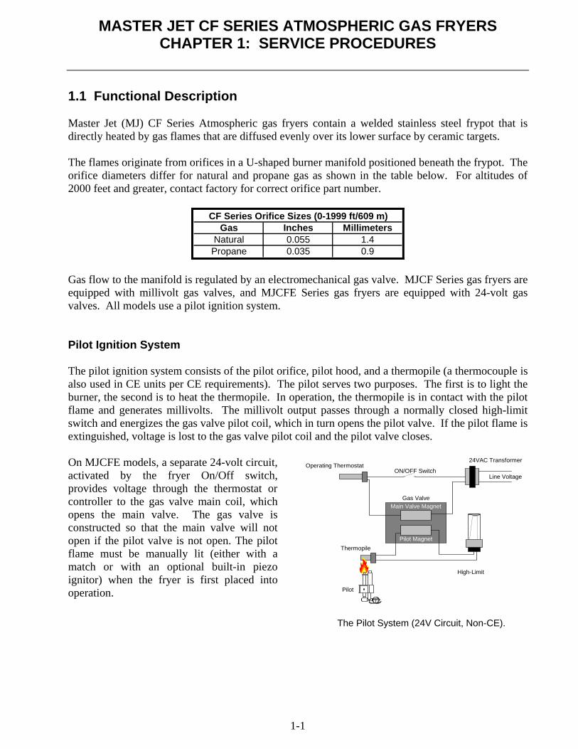
1.1 Functional Description Master Jet (MJ) CF Series Atmospheric gas fryers contain a welded stainless steel frypot that is directly heated by gas flames that are diffused evenly over its lower surface by ceramic targets. The flames originate from orifices in a U-shaped burner manifold positioned beneath the frypot. The orifice diameters differ for natural and propane gas as shown in the table below. For altitudes of 2000 feet and greater, contact factory for correct orifice part number.
Gas Inches MillimetersNatural 0.055 1.4Propane 0.035 0.9
CF Series Orifice Sizes (0-1999 ft/609 m)
Gas flow to the manifold is regulated by an electromechanical gas valve. MJCF Series gas fryers are equipped with millivolt gas valves, and MJCFE Series gas fryers are equipped with 24-volt gas valves. All models use a pilot ignition system. Pilot Ignition System The pilot ignition system consists of the pilot orifice, pilot hood, and a thermopile (a thermocouple is also used in CE units per CE requirements). The pilot serves two purposes. The first is to light the burner, the second is to heat the thermopile. In operation, the thermopile is in contact with the pilot flame and generates millivolts. The millivolt output passes through a normally closed high-limit switch and energizes the gas valve pilot coil, which in turn opens the pilot valve. If the pilot flame is extinguished, voltage is lost to the gas valve pilot coil and the pilot valve closes. On MJCFE models, a separate 24-volt circuit, activated by the fryer On/Off switch, provides voltage through the thermostat or controller to the gas valve main coil, which opens the main valve. The gas valve is constructed so that the main valve will not open if the pilot valve is not open. The pilot flame must be manually lit (either with a match or with an optional built-in piezo ignitor) when the fryer is first placed into operation.
High-Limit
Main Valve Magnet
Pilot MagnetThermopile
Pilot
Gas Valve
Operating Thermostat24VAC Transformer
Line VoltageON/OFF Switch
The Pilot System (24V Circuit, Non-CE).
MASTER JET CF SERIES ATMOSPHERIC GAS FRYERS
CHAPTER 1: SERVICE PROCEDURES
1-2
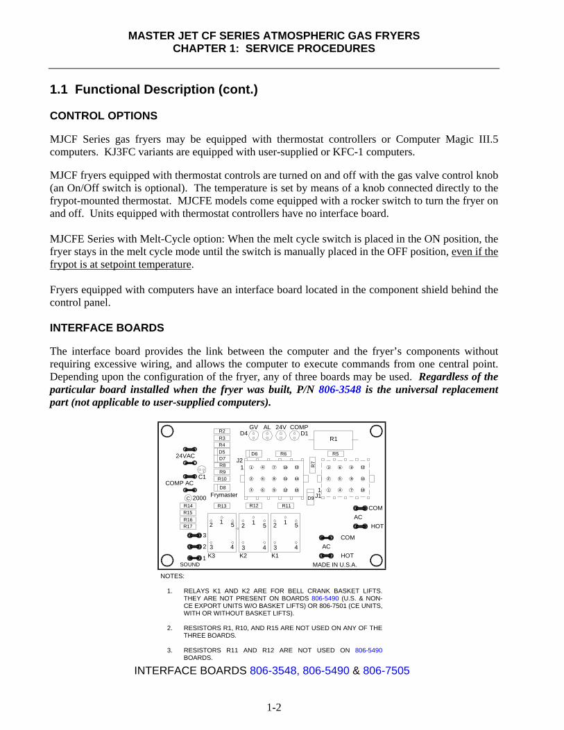
1.1 Functional Description (cont.) CONTROL OPTIONS MJCF Series gas fryers may be equipped with thermostat controllers or Computer Magic III.5 computers. KJ3FC variants are equipped with user-supplied or KFC-1 computers. MJCF fryers equipped with thermostat controls are turned on and off with the gas valve control knob (an On/Off switch is optional). The temperature is set by means of a knob connected directly to the frypot-mounted thermostat. MJCFE models come equipped with a rocker switch to turn the fryer on and off. Units equipped with thermostat controllers have no interface board. MJCFE Series with Melt-Cycle option: When the melt cycle switch is placed in the ON position, the fryer stays in the melt cycle mode until the switch is manually placed in the OFF position, even if the frypot is at setpoint temperature. Fryers equipped with computers have an interface board located in the component shield behind the control panel. INTERFACE BOARDS The interface board provides the link between the computer and the fryer’s components without requiring excessive wiring, and allows the computer to execute commands from one central point. Depending upon the configuration of the fryer, any of three boards may be used. Regardless of the particular board installed when the fryer was built, P/N 806-3548 is the universal replacement part (not applicable to user-supplied computers).
NOTES:
1. RELAYS K1 AND K2 ARE FOR BELL CRANK BASKET LIFTS. THEY ARE NOT PRESENT ON BOARDS 806-5490 (U.S. & NON-CE EXPORT UNITS W/O BASKET LIFTS) OR 806-7501 (CE UNITS, WITH OR WITHOUT BASKET LIFTS).
2. RESISTORS R1, R10, AND R15 ARE NOT USED ON ANY OF THE
THREE BOARDS.
3. RESISTORS R11 AND R12 ARE NOT USED ON 806-5490 BOARDS.
INTERFACE BOARDS 806-3548, 806-5490 & 806-7505
1 K3SOUND
R17
R15R16
2
3
K2 K13 4
52 1
CR13
D8
2000
R9C1 R10
COMP AC
D7
R4D5
R2R3
24VACR8
R12
D6
GVD4
R6
AL 24V
J2
Frymaster
R14
MADE IN U.S.A.HOT
AC
D9
AC
COM
HOT
J1
R7
R1
R5
COM
COMPD1
R11
1
1
3 4
52 1
3 4
52 1
1
2
3
4
5
6
7
8
9
10
11
12
13
14
15 1
2
3
4
5
6
7
8
9
10
11
12
MASTER JET CF SERIES ATMOSPHERIC GAS FRYERS
CHAPTER 1: SERVICE PROCEDURES
1-3
1.1 Functional Description (cont.)
TestMeter
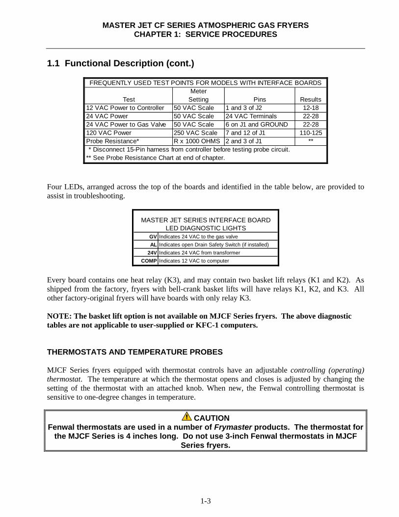
Setting Pins Results12 VAC Power to Controller 50 VAC Scale 1 and 3 of J2 12-1824 VAC Power 50 VAC Scale 24 VAC Terminals 22-2824 VAC Power to Gas Valve 50 VAC Scale 6 on J1 and GROUND 22-28120 VAC Power 250 VAC Scale 7 and 12 of J1 110-125Probe Resistance* R x 1000 OHMS 2 and 3 of J1 **
FREQUENTLY USED TEST POINTS FOR MODELS WITH INTERFACE BOARDS
** Disconnect 15-Pin harness from controller before testing probe circuit.** See Probe Resistance Chart at end of chapter.
Four LEDs, arranged across the top of the boards and identified in the table below, are provided to assist in troubleshooting.
GV Indicates 24 VAC to the gas valveAL Indicates open Drain Safety Switch (if installed)
24V Indicates 24 VAC from transformerCOMP Indicates 12 VAC to computer
MASTER JET SERIES INTERFACE BOARDLED DIAGNOSTIC LIGHTS
Every board contains one heat relay (K3), and may contain two basket lift relays (K1 and K2). As shipped from the factory, fryers with bell-crank basket lifts will have relays K1, K2, and K3. All other factory-original fryers will have boards with only relay K3. NOTE: The basket lift option is not available on MJCF Series fryers. The above diagnostic tables are not applicable to user-supplied or KFC-1 computers. THERMOSTATS AND TEMPERATURE PROBES MJCF Series fryers equipped with thermostat controls have an adjustable controlling (operating) thermostat. The temperature at which the thermostat opens and closes is adjusted by changing the setting of the thermostat with an attached knob. When new, the Fenwal controlling thermostat is sensitive to one-degree changes in temperature.
CAUTION Fenwal thermostats are used in a number of Frymaster products. The thermostat for
the MJCF Series is 4 inches long. Do not use 3-inch Fenwal thermostats in MJCF Series fryers.

MASTER JET CF SERIES ATMOSPHERIC GAS FRYERS
CHAPTER 1: SERVICE PROCEDURES
1-4
1.1 Functional Description (cont.) MJCFE Series fryers equipped with computers have a temperature probe. In these units, the probe resistance varies directly with the temperature. That is, as the temperature rises, so does resistance at a rate of approximately 2 ohms for every 1° (F or C). Circuitry in the computer monitors the probe resistance and controls burner firing when the resistance exceeds or falls below programmed temperatures (setpoints). The temperatures are programmed by means of a keypad on the face of the computer. All MJCF Series Atmospheric gas fryers are equipped with a high-limit thermostat. In the event that the fryer fails to properly control the oil temperature, the high-limit thermostat prevents the fryer from overheating to the flash point. The high-limit thermostat acts as a normally closed power switch that opens when exposed to temperatures in the range of 415°F to 435°F (213°C to 224°C). The high-limit thermostat is the same for CE and Non-CE applications. When a replacement high-limit thermostat is ordered, ensure the kit appropriate for the valve in use is ordered. 1.2 Accessing Fryers for Servicing
DANGER Moving a fryer filled with oil may cause spilling or splattering of hot liquid. Follow
the draining instructions in the Operator’s manual that shipped with the fryer. 1. Shut off the gas supply to the unit. Unplug the power cord(s). Disconnect the unit from the gas
supply. 2. Remove any attached restraining devices. 3. Relocate the fryer for service accessibility. 4. After servicing is complete, reconnect the unit to the gas supply, reattach restraining devices,
and plug in the electrical cords.
MASTER JET CF SERIES ATMOSPHERIC GAS FRYERS
CHAPTER 1: SERVICE PROCEDURES
1-5
1.3 Checking Burner Manifold Gas Pressure
WARNING This task should be performed by qualified service personnel only.
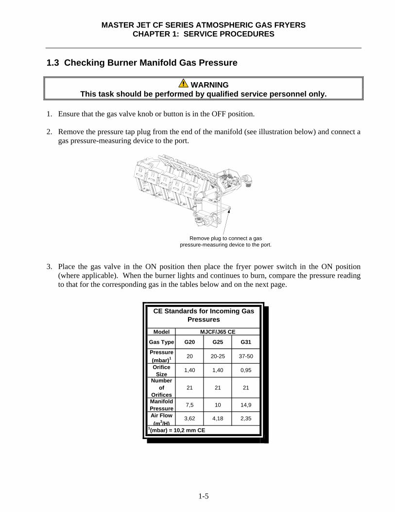
1. Ensure that the gas valve knob or button is in the OFF position. 2. Remove the pressure tap plug from the end of the manifold (see illustration below) and connect a
gas pressure-measuring device to the port.
Remove plug to connect a gaspressure-measuring device to the port.
3. Place the gas valve in the ON position then place the fryer power switch in the ON position
(where applicable). When the burner lights and continues to burn, compare the pressure reading to that for the corresponding gas in the tables below and on the next page.
Model
Gas Type G20 G25 G31
Pressure (mbar)1 20 20-25 37-50
Number of
Orifices21 21 21
Manifold Pressure 7,5 10 14,9
CE Standards for Incoming Gas Pressures
MJCF/J65 CE
OrificeSize
1,40 1,40 0,95
1(mbar) = 10,2 mm CE
Air Flow(m3/H)
3,62 4,18 2,35
MASTER JET CF SERIES ATMOSPHERIC GAS FRYERS
CHAPTER 1: SERVICE PROCEDURES
1-6
1.3 Checking Burner Manifold Gas Pressure (cont.)
Non-CE Standardfor Incoming Gas Pressures
Gas Minimum Maximum
Natural6" W.C.1.49 kPa
14.93 mbar
14" W.C.3.48 kPa
34.84 mbar
LP11" W.C.2.74 kPa
27.37 mbar
14" W.C.3.48 kPa
34.84 mbar
Gas
Natural
LP8.25" W.C.
2.0 kPa20.0 mbar
Pressure
Non-CE Standard
3.5" W.C..75 kPa7.5 mbar
for Burner Manifold Gas Pressures
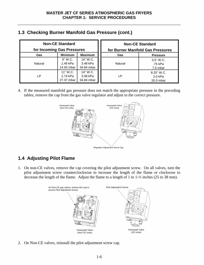
4. If the measured manifold gas pressure does not match the appropriate pressure in the preceding
tables, remove the cap from the gas valve regulator and adjust to the correct pressure.
Honeywell Valve(Non-CE Units)
Honeywell Valve(CE Units)
Regulator Adjustment Screw Cap 1.4 Adjusting Pilot Flame 1. On non-CE valves, remove the cap covering the pilot adjustment screw. On all valves, turn the
pilot adjustment screw counterclockwise to increase the length of the flame or clockwise to decrease the length of the flame. Adjust the flame to a length of 1 to 1-½ inches (25 to 38 mm).
Honeywell Valve(Non-CE Units)
Honeywell Valve(CE Units)
Pilot Adjustment ScrewOn Non-CE gas valves, remove this cap toaccess Pilot Adjustment Screw.
2. On Non-CE valves, reinstall the pilot adjustment screw cap.
MASTER JET CF SERIES ATMOSPHERIC GAS FRYERS
CHAPTER 1: SERVICE PROCEDURES
1-7
1.5 Cleaning Gas Valve Vent Tube 1. Carefully unscrew the vent tube from the gas valve. NOTE: The vent tube may be straightened
for ease in removal.
2. Pass a piece of ordinary binding wire (.052 inch diameter) or equivalent through the tube to remove any obstruction.
3. Remove the wire, and then blow through the tube to ensure it is clear.
4. Reinstall tube and bend it so that the opening is pointing downward. 1.6 Adjusting Burner Ceramic Target Spacing and Alignment
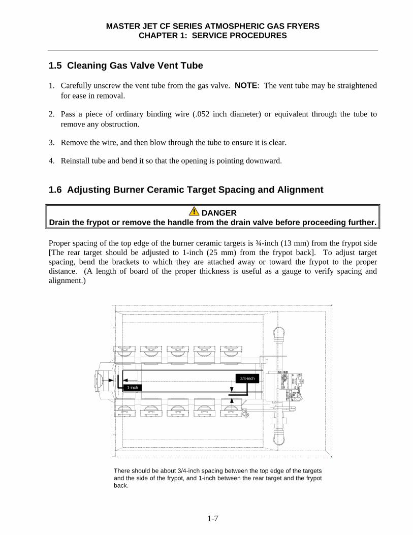
DANGER Drain the frypot or remove the handle from the drain valve before proceeding further. Proper spacing of the top edge of the burner ceramic targets is ¾-inch (13 mm) from the frypot side [The rear target should be adjusted to 1-inch (25 mm) from the frypot back]. To adjust target spacing, bend the brackets to which they are attached away or toward the frypot to the proper distance. (A length of board of the proper thickness is useful as a gauge to verify spacing and alignment.)
There should be about 3/4-inch spacing between the top edge of the targetsand the side of the frypot, and 1-inch between the rear target and the frypotback.
3/4-inch
1-inch
MASTER JET CF SERIES ATMOSPHERIC GAS FRYERS
CHAPTER 1: SERVICE PROCEDURES
1-8
1.7 Calibrating Thermostat Control 1. Fill the frypot to the lower OIL-LEVEL line with oil. If solid shortening is used, it must be
tightly packed into the frypot. 2. Light the pilot. (Refer to Installation and Operation Manual that shipped with the fryer for
detailed lighting instructions.) 3. Insert a good grade thermometer or pyrometer into the frypot, about one inch from the
thermostat. 4. Set the thermostat to 325°F (163°C). 5. Allow the fryer to heat to 325°F (163°C) and cycle on and off three times. 6. With the oil temperature at 325°F (163°C) turn the flexible shaft slowly clockwise until the
burner shuts off. (Turning the shaft counterclockwise causes the temperature to increase and the burner to light; turning it clockwise causes the temperature to decrease and shut off.)
7. Allow the fryer to sit for a few minutes and then slowly turn the flexible shaft counterclockwise
until the burner lights. 8. Repeat steps 6 and 7 at least three times to ensure an accurate setting is obtained. The thermostat
control is calibrated if the burner lights as the oil cools to 325°F (163°C) – not when the burner shuts off as the temperature rises.
9. Compare the reading of the pyrometer to the setting on the thermostat plate. The position of the
knob on the thermostat and the reading from the pyrometer should be within 5°F (3°C) of each other.
10. If not, loosen the setscrew and stop screw securing the thermostat shaft extension to the flexible
shaft. Remove the extension to expose the slot in the end of the flexible shaft. Use a flat-blade screwdriver to adjust the thermostat.
11. Once the calibration point of 325°F (163°C) is determined, allow the burner to cycle on and off
at least three times to ensure it will light at the calibrated temperature. 12. Carefully replace the thermostat shaft extension, ensuring that the stop screw is pointed straight
up. Tighten the stop screw and locking nut and the setscrew, being careful not to rotate the flexible shaft.
CAUTION The thermostat flexible shaft must not be rotated while installing the thermostat
shaft extension!
When handling the thermostat, do not rotate the shaft more than two turns in either direction. Doing so will cause damage to the thermostat.
MASTER JET CF SERIES ATMOSPHERIC GAS FRYERS
CHAPTER 1: SERVICE PROCEDURES
1-9
1.7 Calibrating Thermostat Control (cont.) 13. Close the fryer control panel and replace the screws in the upper corners. 14. Reinstall the thermostat knob with its pointer aligned with the 325°F (163°C) index mark on the
temperature dial. 15. Reconnect the fryer to the electrical power supply.
1.8 Replacing Fryer Components 1.8.1 Replacing Computer
1. Disconnect the fryer from the electrical supply.
2. The controller bezel is held in place by
tabs at the top and bottom. Slide the bezel up to disengage the lower tabs. Then slide the bezel down to disengage the upper tabs.
3. Remove the two screws in the upper
corners of the control panel and swing the panel open from the top, allowing it to rest on its hinge tabs.
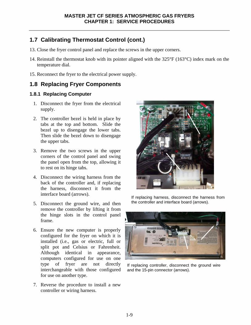
4. Disconnect the wiring harness from the
back of the controller and, if replacing the harness, disconnect it from the interface board (arrows).
5. Disconnect the ground wire, and then
remove the controller by lifting it from the hinge slots in the control panel frame.
6. Ensure the new computer is properly
configured for the fryer on which it is installed (i.e., gas or electric, full or split pot and Celsius or Fahrenheit. Although identical in appearance, computers configured for use on one type of fryer are not directly interchangeable with those configured for use on another type.
7. Reverse the procedure to install a new
controller or wiring harness.
If replacing harness, disconnect the harness from the controller and interface board (arrows).
If replacing controller, disconnect the ground wire and the 15-pin connector (arrows).
MASTER JET CF SERIES ATMOSPHERIC GAS FRYERS
CHAPTER 1: SERVICE PROCEDURES
1-10
1.8.2 Replacing Operating Thermostat
CAUTION The thermostat must be calibrated after installation is complete. Refer to Section 1.7
for calibration instructions.
When handling the thermostat, do not rotate the shaft more than two turns in either direction. Doing so will cause damage to the thermostat.
1. Disconnect the fryer from the electrical supply and drain the frypot. 2. Loosen the setscrew securing the thermostat knob and remove the knob. Remove the screws
from the upper left and right corners of the control panel. The control panel is hinged at the bottom and will swing open from the top.
3. Disconnect the 9-pin connector and remove the control panel from the fryer by disengaging its
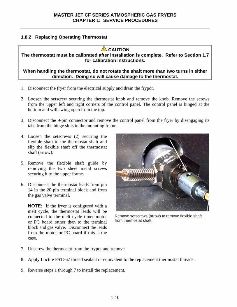
tabs from the hinge slots in the mounting frame. 4. Loosen the setscrews (2) securing the
flexible shaft to the thermostat shaft and slip the flexible shaft off the thermostat shaft (arrow).
5. Remove the flexible shaft guide by
removing the two sheet metal screws securing it to the upper frame.
6. Disconnect the thermostat leads from pin
14 in the 20-pin terminal block and from the gas valve terminal. NOTE: If the fryer is configured with a melt cycle, the thermostat leads will be connected to the melt cycle timer motor or PC board rather than to the terminal block and gas valve. Disconnect the leads from the motor or PC board if this is the case.
7. Unscrew the thermostat from the frypot and remove. 8. Apply Loctite PST567 thread sealant or equivalent to the replacement thermostat threads. 9. Reverse steps 1 through 7 to install the replacement.
Remove setscrews (arrow) to remove flexible shaft from thermostat shaft.
MASTER JET CF SERIES ATMOSPHERIC GAS FRYERS
CHAPTER 1: SERVICE PROCEDURES
1-11
1.8.3 Replacing Temperature Probe 1. Disconnect the fryer from the electrical supply. 2. Drain the frypot. 3. Remove the screws from the upper left and right corners of the control panel. The panel is
hinged at the bottom and will swing open from the top. 4. Unplug the wiring harness from the back of the controller and disconnect the grounding wire
(see Section 1.8.1, Step 4). 5. Remove the controller from the fryer by lifting it from the hinge slots in the control panel frame. 5. Remove the two screws from the base of the interface board mounting-bracket. 6. Disconnect the 12-pin plug from the back of the interface board and lay the board in the left end
of the compartment with all other wires still connected. 7. Remove the 12-volt transformer from the component shield and lay it in the left end of the
compartment with wires still connected. 8. Using a pin-pusher, remove the temperature probe wires (pins 1 and 2) from the 12-pin plug
disconnected in step 7. 9. Unscrew the temperature probe from the frypot and remove. 10. Apply Loctite PST567 thread sealant or equivalent to new probe threads. 11. Reverse steps 1 through 10 to install the replacement probe. 1.8.4 Replacing High-Limit Thermostat – Operating Thermostat Controls 1. Disconnect the fryer from the electrical supply. 2. Drain the frypot. 3. Loosen the setscrew securing the thermostat knob and remove the knob. Remove the screws
from the upper left and right corners of the control panel. The control panel is hinged at the bottom and will swing open from the top.
4. Disconnect the 9-pin connector and remove the control panel from the fryer by disengaging its
tabs from the hinge slots in the mounting frame. 5. Disconnect the high-limit thermostat leads from the gas valve pilot coil.
MASTER JET CF SERIES ATMOSPHERIC GAS FRYERS
CHAPTER 1: SERVICE PROCEDURES
1-12
1.8.4 Replacing High-Limit Thermostat – Operating Thermostat Controls (cont.) 6. Unscrew the high-limit thermostat from the frypot and remove. 7. Apply Loctite PST567 thread sealant or equivalent to the replacement thermostat threads. 8. Reverse steps 1 through 7 to install the replacement. 1.8.5 Replacing High-Limit Thermostat – Computer Controls 1. Disconnect the fryer from the electrical power supply. 2. Drain the frypot. 3. Remove the screws from the upper left and right corners of the computer panel. The computer is
hinged at the bottom and will swing open from the top. 4. Unplug the wiring harness and disconnect the grounding wire from the controller. 5. Remove the controller from the fryer by lifting it from the hinge slots in the fryer control panel
frame. 6. Remove the two screws from the base of the interface board-mounting bracket. 7. Disconnect the 12-pin plug from the back of the interface board and lay the board in the right end
of the compartment with all other wires still connected. 8. Remove the 12-volt transformer and lay it in the right end of the compartment with wires still
connected. 9. Remove the high-limit thermostat wires from the gas valve pilot coil and pull them up through
the control shield. 10. Unscrew the high-limit thermostat from the frypot and remove. 11. Apply Loctite PST567 thread sealant or equivalent to the replacement thermostat’s threads and
screw it into the frypot. 12. Attach the appropriate terminals (furnished in the replacement thermostat kit) to the thermostat
leads. 13. Reverse steps 1 through 9 to complete installation of the replacement thermostat.
MASTER JET CF SERIES ATMOSPHERIC GAS FRYERS
CHAPTER 1: SERVICE PROCEDURES
1-13
1.8.6 Replacing Heat Mode Indicator Light – Operating Thermostat Controls 1. Disconnect the fryer from the electrical supply. 2. Loosen the setscrew securing the thermostat knob and remove the knob. Remove the screws
from the upper left and right corners of the control panel. The control panel is hinged at the bottom and will swing open from the top.
3. Disconnect the 9-pin connector and remove the control panel from the fryer by disengaging its
tabs from the hinge slots in the mounting frame. 4. Carefully press the light out from the back of the control panel. Disconnect one wire at a time
and reconnect it to the replacement light until all wires are transferred. 5. Carefully press the light back into the control panel. 6. Reverse steps 1-3 to reassemble the fryer. 1.8.7 Replacing Power/Melt Cycle Switch – Operating Thermostat Controls NOTE: The Power/Melt-Cycle Switch, P/N 807-1404, has been replaced with a new switch, P/N 807-3498. When ordering the new switch, order Kit 826-1792, which contains the new switch and wiring instructions. The new switch is wired differently than the old one. Ensure the new switch is wired properly before operating fryer. Consult P/N 819-5889 (MJCF, MJ45 Switch Replacement Instructions) for further detail. 1. Disconnect the fryer from the electrical supply. 2. Loosen the setscrew securing the thermostat knob and remove the knob. Remove the screws
from the upper left and right corners of the control panel. The control panel is hinged at the bottom and will swing open from the top.
3. Disconnect the 9-pin connector and remove the control panel from the fryer by disengaging its
tabs from the hinge slots in the mounting frame. 4. Using a flat-tipped screwdriver, disconnect the chrome bezel from the tabs on the switch and
press the switch out from the front. 5. Carefully press the new switch back into the chrome bezel, ensuring the tabs on the switch
engage the slots in the bezel. 6. Disconnect the wires from the old switch and reconnect to the new switch until all wires have
been transferred (see note at the beginning of this procedure). 7. Reverse steps 1-3 to reassemble the fryer.
MASTER JET CF SERIES ATMOSPHERIC GAS FRYERS
CHAPTER 1: SERVICE PROCEDURES
1-14
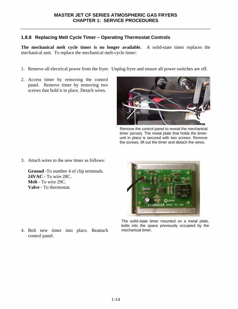
1.8.8 Replacing Melt Cycle Timer – Operating Thermostat Controls The mechanical melt cycle timer is no longer available. A solid-state timer replaces the mechanical unit. To replace the mechanical melt-cycle timer: 1. Remove all electrical power from the fryer. Unplug fryer and ensure all power switches are off. 2. Access timer by removing the control
panel. Remove timer by removing two screws that hold it in place. Detach wires.
3. Attach wires to the new timer as follows:
Ground -To number 4 of clip terminals. 24VAC - To wire 28C. Melt - To wire 29C. Valve - To thermostat.
4. Bolt new timer into place. Reattach
control panel.
Remove the control panel to reveal the mechanical timer (arrow). The metal plate that holds the timer-unit in place is secured with two screws. Remove the screws, lift out the timer and detach the wires.
The solid-state timer mounted on a metal plate, bolts into the space previously occupied by the mechanical timer.

MASTER JET CF SERIES ATMOSPHERIC GAS FRYERS
CHAPTER 1: SERVICE PROCEDURES
1-15
1.8.9 Replacing Burner Ceramic Targets
DANGER Drain the frypot or remove the handle from the drain valve before proceeding further. 1. Disconnect fryer from electrical and gas supplies. 2. On FMCF fryers, remove square-drain sections as necessary to expose burner. 3. Disconnect the wires from the gas valve terminal block, marking each wire to facilitate
connections. 4. Remove the high-limit thermostat wires from the gas valve pilot coil. 5. Disconnect the pipe union collar at the left side of the gas valve (arrow).
6. Remove front burner shields to access burner assembly. 7. Remove the burner heat shield hanger screws at the front of the burner and remove the heat
shield. 8. Remove the burner hanger screws and lower the front of the main burner. Pull it forward to clear
the rear burner hanger, and then lower the burner to the floor. 9. Raise the front of the fryer enough to slide the burner from under the fryer cabinet.
Disconnect union (arrow) to remove burner manifold assembly.
MASTER JET CF SERIES ATMOSPHERIC GAS FRYERS
CHAPTER 1: SERVICE PROCEDURES
1-16
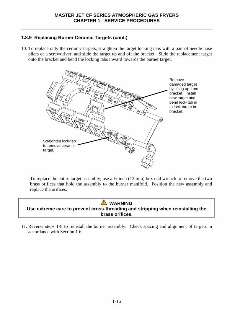
1.8.9 Replacing Burner Ceramic Targets (cont.) 10. To replace only the ceramic targets, straighten the target locking tabs with a pair of needle nose
pliers or a screwdriver, and slide the target up and off the bracket. Slide the replacement target onto the bracket and bend the locking tabs inward towards the burner target.
To replace the entire target assembly, use a ½-inch (13 mm) box end wrench to remove the two brass orifices that hold the assembly to the burner manifold. Position the new assembly and replace the orifices.
WARNING
Use extreme care to prevent cross-threading and stripping when reinstalling the brass orifices.
11. Reverse steps 1-8 to reinstall the burner assembly. Check spacing and alignment of targets in
accordance with Section 1.6.
Straighten lock-tab to remove ceramic target.
Remove damaged target by lifting up from bracket. Install new target and bend lock-tab in to lock target in bracket.
MASTER JET CF SERIES ATMOSPHERIC GAS FRYERS
CHAPTER 1: SERVICE PROCEDURES
1-17
1.8.10 Replacing Gas Valve
DANGER Drain the frypot or remove the handle from the drain valve before proceeding further. 1. Disconnect fryer from electrical and gas supplies 2. Disconnect the wires from the gas valve terminal block, marking each wire to facilitate
reconnections. 3. Remove the high-limit thermostat wire from the gas valve pilot coil. 4. Disconnect the pilot gas line fitting from the gas valve. 5. Disconnect the pipe union collars to the left and right of the gas valve and remove the valve. 6. Remove the pipefittings from the old gas valve and install on the replacement valve, using
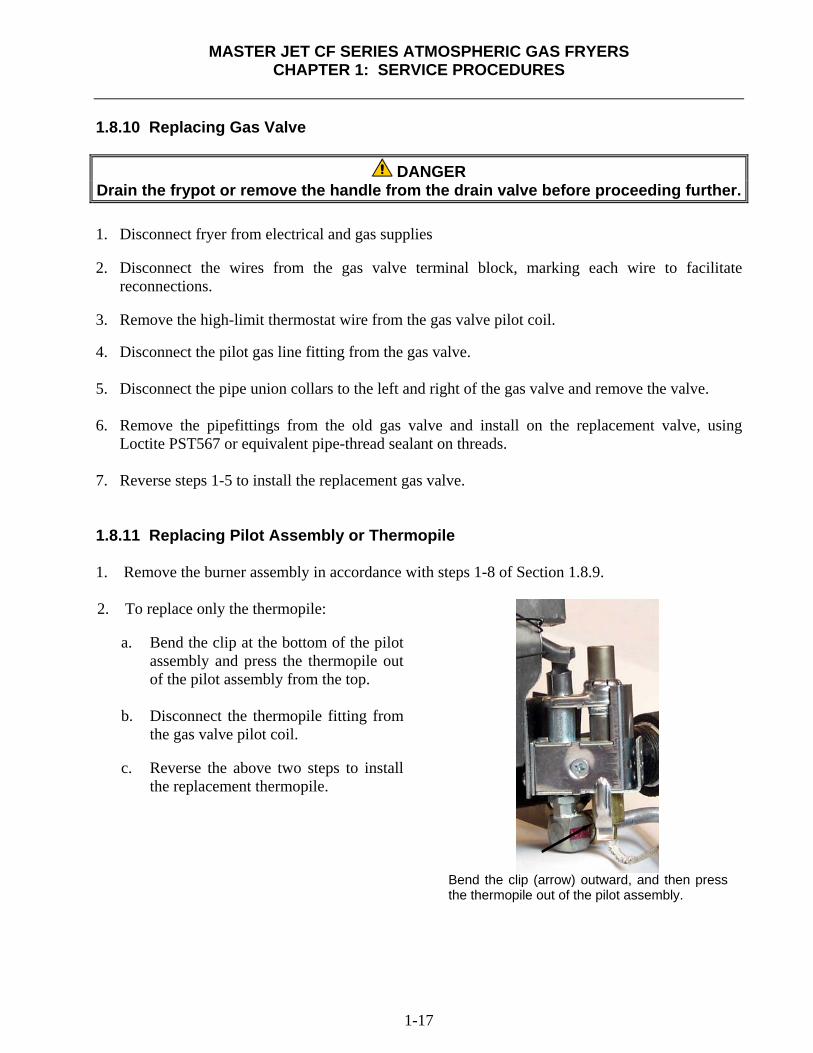
Loctite PST567 or equivalent pipe-thread sealant on threads. 7. Reverse steps 1-5 to install the replacement gas valve. 1.8.11 Replacing Pilot Assembly or Thermopile 1. Remove the burner assembly in accordance with steps 1-8 of Section 1.8.9. 2. To replace only the thermopile:
a. Bend the clip at the bottom of the pilot assembly and press the thermopile out of the pilot assembly from the top.
b. Disconnect the thermopile fitting from
the gas valve pilot coil.
c. Reverse the above two steps to install the replacement thermopile.
Bend the clip (arrow) outward, and then press the thermopile out of the pilot assembly.
MASTER JET CF SERIES ATMOSPHERIC GAS FRYERS
CHAPTER 1: SERVICE PROCEDURES
1-18
1.8.11 Replacing Pilot Assembly or Thermopile (cont.) 3. To replace the complete pilot assembly:
a. Disconnect the pilot tubing from the bottom of the pilot assembly.
b. Remove the screw from the pilot mounting-bracket to release the pilot assembly.
c. Disconnect the thermopile fitting from the gas valve pilot coil.
d. Reverse steps a through c to install the replacement pilot assembly. 4. Reinstall the burner assembly by reversing steps 1-8 of Section 1.8.9. 1.8.12 Replacing Frypot 1. Drain the frypot. 2. Remove all accessories (e.g., frypot covers, basket lift arms, etc.) from the fryer. 3. Disconnect the fryer from gas and electrical supplies. 4. Remove the screws from the top-cap above the control panel and lift it up and off the fryer(s). 5. If the fryer is equipped with other than a thermostat control, skip to Step 10. 6. Perform steps 1-6, section 1.8.2.
CAUTION When handling the thermostat, do not rotate the shaft more than two turns in either
direction. Doing so will cause damage to the thermostat. 7. For fryers with other than thermostat controls, perform steps 1-4, section 1.8.1. 8. Disconnect the 12-pin plug from the back of the interface board. Use a pin pusher to remove the
temperature probe leads (pins 1 and 2) and the high-limit thermostat leads (pins 6 and 8) from the plug. Leave all other wires connected. Leave the interface board lying on the shield.
9. Remove the louvered frame above the control panel opening. 10. Remove the screws securing the component shield to the fryer. 11. Disconnect the wires from components in component shield and mark to facilitate reconnection. 12. Disconnect the wires from the gas valve terminal block. Mark each wire to facilitate
reconnection.
MASTER JET CF SERIES ATMOSPHERIC GAS FRYERS
CHAPTER 1: SERVICE PROCEDURES
1-19
1.8.12 Replacing Frypot (cont.) 13. Remove the cover from the safety drain switch, disconnect the wires from the switch, and pull
them out of the switch box. 14. Pull up and forward on the component shield to clear the rear mounting stud on the front of the
frypot and remove it from the fryer by rotating its right side up and to the left. 15. Disconnect the pipe union on the right side of the gas valve. 16. On FMCF fryers, remove the section of square drain from the drain valve of the frypot to be
removed. 17. Remove the frypot hold-down bracket. 18. Remove the screws from the flue cap sides and back, and lift it clear of the fryer(s). 19. Remove the oil return line from the front of the frypot to be removed. 20. Lift the complete frypot assembly (frypot, burner, gas valve, and flue) from the fryer cabinet. 21. Transfer the burner heat shield and burner to the replacement frypot. 22. Remove the drain valve, thermostat or temperature probe, and high-limit thermostat and install
on replacement frypot.
CAUTION Before installing the thermostat/temperature probe, high-limit thermostat, and drain valve on the replacement frypot, clean their threads and apply Loctite PST567 thread
sealant or equivalent to the threads. 23. Reverse steps 1-22 to reassemble the fryer.
MASTER JET CF SERIES ATMOSPHERIC GAS FRYERS
CHAPTER 1: SERVICE PROCEDURES
1-20
1.9 Troubleshooting and Problem Isolation Because it is not feasible to attempt to include in this manual every conceivable problem or trouble condition that might be encountered, this section is intended to provide technicians with a general knowledge of the broad problem categories associated with this equipment, and the probable causes of each. With this knowledge, the technician should be able to isolate and correct any problem encountered. Problems likely encountered can be grouped into six broad categories: 1. Pilot/Ignition failures 2. Improper burner functioning 3. Improper temperature control 4. Computer-related problems
5. Filtration problems 6. Leakage
The probable causes of each category are discussed in the following sections. Troubleshooting charts are included at the end of the chapter to assist in identifying some of the more common problems. 1.9.1 Pilot/Ignition Failures There are two categories: no pilot flame and unreliable flame. No pilot flame 1. No gas or insufficient gas supply. 2. Clogged pilot orifice. 3. Air in gas lines (usually in new installations). 4. Open or grounded high limit. Unreliable flame 1. Loose/corroded wire connections. 2. Low or no voltage out of thermopile / thermocouple (CE units). 3. Defective gas valve.
MASTER JET CF SERIES ATMOSPHERIC GAS FRYERS
CHAPTER 1: SERVICE PROCEDURES
1-21
1.9.1 Pilot/Ignition Failures (cont.) Ignition failures occur when the 24VAC power supply to the gas valve is interrupted, when the gas supply is interrupted, or when the pilot flame is extinguished. There are three primary reasons for ignition failure, listed in order of probability: 1. Problems related to the gas and/or electrical power supplies. 2. Problems related to the electronic circuits. 3. Problems related to the gas valve. PROBLEMS RELATED TO THE GAS AND/OR ELECTRICAL POWER SUPPLIES The main indicators of this are that an entire battery of fryers fails to light and/or there are no indicator lights illuminated on the fryer experiencing ignition failure. Verify that the quick disconnect hose is properly connected, the fryer is plugged in, the main gas supply valve is open, and the circuit breaker for the fryer electrical supply is not tripped. PROBLEMS RELATED TO THE ELECTRONIC CIRCUITS If gas and electrical power are being supplied to the fryer, the next most likely cause of ignition failure is a problem in the 24 VAC circuit of the pilot system. If the fryer is equipped with a Filter Magic II filtration system, first verify that the drain valve is fully closed. (The valve is attached to a microswitch that must be closed for power to reach the gas valve. Often, although the valve handle appears to be in the closed position, the microswitch is still open.) If the valve is fully closed, or the fryer does not have a filtration system, refer to the troubleshooting tables in this chapter. PROBLEMS RELATED TO THE GAS VALVE If the problem is not in the 24 VAC circuit of the pilot system, it is most likely in the gas valve itself, but before replacing the gas valve refer to the troubleshooting tables in this chapter.
MASTER JET CF SERIES ATMOSPHERIC GAS FRYERS
CHAPTER 1: SERVICE PROCEDURES
1-22
1.9.2 Improper Burner Functioning The burner ignites but exhibits abnormal characteristics such as "popping", incomplete lighting of the burner, fluctuating flame intensity, and flames "rolling" out of the fryer. "Popping" indicates delayed ignition. In this condition, the main gas valve is opening but the burner is not immediately lighting. When ignition does take place, the excess gas "explodes" into flame, rather than smoothly igniting. The primary causes of popping are:
• Incorrect or fluctuating gas pressure • Misdirected or weak pilot flame • Burner deflector targets out of alignment or missing • Clogged burner orifices • Inadequate make-up air • Clogged vent tube, causing incorrect gas pressure If popping occurs only during peak operating hours, the problem may be incorrect or fluctuating gas pressure. Verify that the incoming gas pressure (pressure to the gas valve) is in accordance with the appropriate CE or Non-CE standards found in the tables on Pages 1-5 and 1-6, and that the pressure remains constant throughout all hours of usage. Refer to Section 1.3 for the procedure for checking the burner gas pressure. If popping is consistent during all hours of operation, verify that the pilot is properly positioned above the burner orifice and that the pilot pressure is correct. Correct pilot pressure is indicated by a flame 1 to 1-½" (25 to 38 mm) long. Refer to Section 1.4 for the pilot flame adjustment procedure. Clogged burner orifices, especially those near the pilot, are also likely causes of delayed ignition. Clogged orifices are indicated by no flame, flames that are orange-colored, and flames that shoot out at an angle from the rest. Another cause of popping is an insufficient air supply or drafts that are blowing the pilot flame away from the burner. Check for "negative pressure" conditions in the kitchen area. If when the door is opened to the kitchen and a rush of incoming air is felt, this indicates that more air is being exhausted than is being replenished and the burners may have insufficient combustion air. If the fryer’s gas and air supplies are okay, the problem most likely is with one of the electrical components. Examine the computer for signs of melting/distortion and/or discoloration due to excessive heat buildup in the fryer. (This condition usually indicates improper flue performance.). A discolored or distorted computer should be replaced immediately. To prevent recurring problems, correct the condition immediately. The burner lighting on one side only may be caused by a missing or misaligned rear deflector target or improper burner manifold pressure. Clogged burner orifices are usually the cause of gaps in burner firing.
MASTER JET CF SERIES ATMOSPHERIC GAS FRYERS
CHAPTER 1: SERVICE PROCEDURES
1-23
1.9.2 Improper Burner Functioning (cont.) Fluctuating flame intensity is normally caused by either improper or fluctuating incoming gas pressure, but may also be the result of variations in the kitchen atmosphere. Verify incoming gas pressure in the same way as for "popping", discussed in the preceding paragraphs. Variations in the kitchen atmosphere are usually caused by air conditioning and/or ventilation unit air-exchange. As the systems start and stop, the pressure in the kitchen may change from positive or neutral to negative, or vice versa. They may also cause changes in airflow patterns that may affect flame intensity. Flames "rolling" out of the fryer are usually an indication of negative pressure in the kitchen. Air is being sucked out of the fryer enclosure and the flames are literally following the air. If negative pressure is not the cause, check for high burner manifold gas pressure in accordance with the procedures in Section 1.3. An obstructed flue, which prevents the fryer from properly exhausting, may also be the cause. An excessively noisy burner, especially with flames visible above the flue opening, may indicate that the burner gas pressure is too high, or it may simply be that the gas valve vent tube is blocked. If the gas pressure is correct and the vent tube is unobstructed, the gas valve regulator is probably defective. Occasionally a burner may apparently be operating correctly, but the fryer has a slow recovery rate. [The recovery rate is the length of time required for the fryer to increase the oil temperature from 250°F to 300°F (121°C to 149°C)]. Low burner manifold pressure and/or misaligned or missing deflector targets are usually the main causes. If both of these causes are ruled out, the probable cause is a gas valve regulator that is out of adjustment. See Section 1.3 to adjust regulator. 1.9.3 Improper Temperature Control Temperature control, including the melt cycle, is a function of several interrelated components, each of which must operate correctly. The principle component is the thermostat (in thermostat control units) or the temperature probe (in fryers equipped with computers). Depending upon the specific configuration of the fryer, other components may include the interface board and the computer. Improper temperature control problems can be categorized into melt cycle problems and failure to control at setpoint problems.

MASTER JET CF SERIES ATMOSPHERIC GAS FRYERS
CHAPTER 1: SERVICE PROCEDURES
1-24
1.9.3 Improper Temperature Control (cont.) MELT CYCLE PROBLEMS NOTE: In early 1999, PC board melt cycle timers replaced melt-cycle timer motors in new fryers. See Section 1.8.8 for retrofit information. In fryers equipped with thermostat controls, the melt cycle is controlled by a mechanical timer or a PC board. Three components that that can fail are the melt-cycle timer, the melt-cycle timer microswitch or the control panel melt cycle On/Off switch. Isolate the defect and replace defective component. In fryers equipped with computers, the problem may be with the computer itself, the temperature probe, or a malfunctioning heat relay on the interface board. Refer to the troubleshooting tables in this chapter. FAILURE TO CONTROL AT SETPOINT In fryers equipped with thermostat controls, the problem will be with the thermostat itself. Possible causes are that the thermostat is out of calibration, the knob or flexible shaft is loose on the thermostat shaft, a thermostat wire is disconnected or broken, or the thermostat is defective. Refer to Section 1.7 for instructions on calibrating the thermostat. In fryers equipped with other types of controls, the problem may be with the temperature probe, the interface board, or the controller. Refer to the troubleshooting tables in this chapter. 1.9.4 Computer-Related Problems Computer Magic III.5 Features Sensitivity or "Stretch Time" Sensitivity or stretch time is a programmable feature that increases the cook time countdown based on variations in the oil temperature from the setpoint. The sensitivity for each product button has 10 settings (0 through 9). A "0" sensitivity setting will disable the feature (no change in cooking time), while a nine will provide the highest sensitivity or most change. The correct sensitivity for any product is based on the product, its density, the setpoint temperature, and the customer’s own requirements.
MASTER JET CF SERIES ATMOSPHERIC GAS FRYERS
CHAPTER 1: SERVICE PROCEDURES
1-25
1.9.4 Computer-Related Problems (cont.) Recovery Time Recovery time is a method of measuring a fryer’s performance. Put simply, it is the time required for the fryer to increase the oil temperature from 250°F to 300°F (121°C to 149°C). This range is used as a standard since ambient kitchen temperatures can affect the test if lower ranges are used. The Computer Magic III.5 performs the recovery test each day as the fryer warms up. An operator can view the results of the test any time the fryer is above the 325°F (163°C) point by pressing the
button and entering the code 1652. The test results will be displayed in the computer’s LED panel in minutes and seconds. An acceptable recovery time for the MJCF Series fryers is 3 minutes, 30 seconds. Common Computer Complaints Most problems concerning computers have to do with programming them. There are four common complaints. The complaints, their causes, and corrective actions are: 1. Fryer constantly displays " ".
Cause: Setpoint incorrect or missing.
Corrective Action: Press 1 6 5 0, enter the correct setpoint using keypad, press again, then
press to lock in the setpoint. 2. Temperature is displayed in Celsius.
Cause: Computer is programmed to display in Celsius.
Corrective Action: Press 1 6 5 8. 3. Temperature is constantly displayed.
Cause: Computer is programmed for constant temperature display.
Corrective Action: Press 1 6 5 L. 4. Computer times down too slowly or too quickly. Cause: Computer is compensating for oil temperature via the sensitivity setting. Corrective Action: Reprogram sensitivity setting for each product in accordance with
programming instructions in the Frymaster Fryer Controllers User’s Manual that shipped with the computer.
MASTER JET CF SERIES ATMOSPHERIC GAS FRYERS
CHAPTER 1: SERVICE PROCEDURES
1-26
1.9.5 Filtration Problems The majority of filtration problems arise from operator error. One of the most common errors is placing the filter paper on the bottom of the filter pan rather than over the filter screen. Whenever the complaint is "the pump is running, but no oil is being filtered", check the installation of the filter paper, and the paper size. While you are checking the filter paper, verify that the O-rings on the bottom of the filter pan, and on the male disconnect (at inside rear of filter cabinet) are present and in good condition. Missing or worn O-rings will allow the pump to suck air and decrease its efficiency. If the pump motor overheats, its thermal overload will trip and the motor will not start until it is reset. If the pump motor does not start, press the red reset switch located on the end of the motor nearest the operator. If the pump then starts, something caused the motor to overheat. It may be just that several frypots were being filtered one after the other and the pump got hot. Letting the pump cool down for at least a half-hour is all that is required in this case. More often, the pump overheated for one of the following reasons: • Shortening has solidified in the pan or filter lines. • Attempt to filter unheated oil or shortening. Cold oil and shortening are thicker and cause the
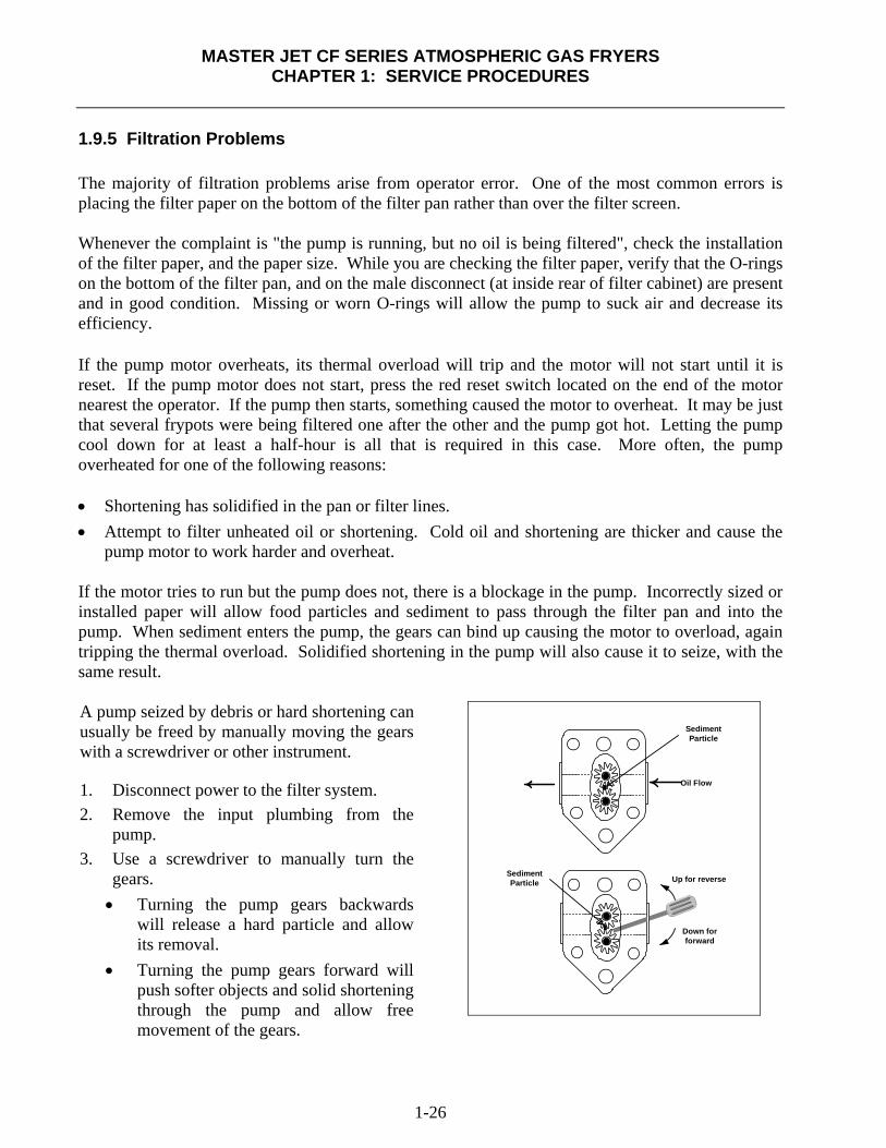
pump motor to work harder and overheat. If the motor tries to run but the pump does not, there is a blockage in the pump. Incorrectly sized or installed paper will allow food particles and sediment to pass through the filter pan and into the pump. When sediment enters the pump, the gears can bind up causing the motor to overload, again tripping the thermal overload. Solidified shortening in the pump will also cause it to seize, with the same result. A pump seized by debris or hard shortening can usually be freed by manually moving the gears with a screwdriver or other instrument. 1. Disconnect power to the filter system. 2. Remove the input plumbing from the
pump. 3. Use a screwdriver to manually turn the
gears. • Turning the pump gears backwards
will release a hard particle and allow its removal.
• Turning the pump gears forward will push softer objects and solid shortening through the pump and allow free movement of the gears.
SedimentParticle
Oil Flow
Up for reverse
Down forforward
SedimentParticle
MASTER JET CF SERIES ATMOSPHERIC GAS FRYERS
CHAPTER 1: SERVICE PROCEDURES
1-27
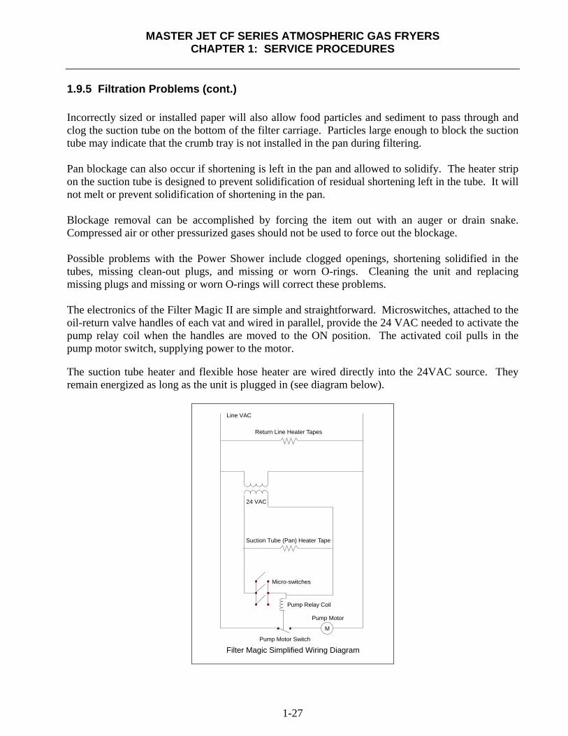
1.9.5 Filtration Problems (cont.) Incorrectly sized or installed paper will also allow food particles and sediment to pass through and clog the suction tube on the bottom of the filter carriage. Particles large enough to block the suction tube may indicate that the crumb tray is not installed in the pan during filtering. Pan blockage can also occur if shortening is left in the pan and allowed to solidify. The heater strip on the suction tube is designed to prevent solidification of residual shortening left in the tube. It will not melt or prevent solidification of shortening in the pan. Blockage removal can be accomplished by forcing the item out with an auger or drain snake. Compressed air or other pressurized gases should not be used to force out the blockage. Possible problems with the Power Shower include clogged openings, shortening solidified in the tubes, missing clean-out plugs, and missing or worn O-rings. Cleaning the unit and replacing missing plugs and missing or worn O-rings will correct these problems. The electronics of the Filter Magic II are simple and straightforward. Microswitches, attached to the oil-return valve handles of each vat and wired in parallel, provide the 24 VAC needed to activate the pump relay coil when the handles are moved to the ON position. The activated coil pulls in the pump motor switch, supplying power to the motor. The suction tube heater and flexible hose heater are wired directly into the 24VAC source. They remain energized as long as the unit is plugged in (see diagram below).
M
Pump Relay Coil
Micro-switches
Pump Motor Switch
Pump Motor
24 VAC
Line VAC
Filter Magic Simplified Wiring Diagram
Return Line Heater Tapes
Suction Tube (Pan) Heater Tape

MASTER JET CF SERIES ATMOSPHERIC GAS FRYERS
CHAPTER 1: SERVICE PROCEDURES
1-28
1.9.6 Leakage Leakage of the frypot is mostly due to improperly sealed high-limits, thermostats/temperature probes, and drain fittings. When installed or replaced, each of these components must be sealed with Loctite PST567 sealant or equivalent to prevent leakage. In very rare cases, a leak may develop along one of the welded edges of the frypot. When this occurs, the frypot must be replaced. If the sides and/or ends of the frypot are coated with oil, the most likely cause is spillage over the top of the frypot rather than leakage. The clamps, which hold the drain tube sections together, may loosen over time as the tubes expand and contract with heating and cooling during use. If the section of drain tube connected to the drain valve is removed for whatever reason, make sure that its grommet is in good condition and properly fitted around the nipple of the drain when it is reinstalled. Also, ensure that the drain tube runs downward from the drain along its whole length and has no low points where oil may accumulate. 1.9.7 Troubleshooting, Millivolt Frying Systems How the Millivolt Circuit Works The voltage output of a thermopile powers the coil of a millivolt gas valve. This output is measured in millivolts or thousandths of one volt. The high-limit thermostat acts as a safety switch. It will de-energize the gas valve when the oil in the fryer’s frypot climbs to 425°F to 450°F. An operating thermostat controls the main coil actuation and acts as the burner control.
High-Limit
Main Valve Magnet
Pilot Magnet
Operating Thermostat
Thermopile
Pilot
Gas Valve
MASTER JET CF SERIES ATMOSPHERIC GAS FRYERS
CHAPTER 1: SERVICE PROCEDURES
1-29
Optional ON-OFF switch
High-Limit Thermostat
Operating Thermostat
Pilot Generator
FENWALL Operating
Thermostat
HO
NE
YW
ELL
1/2
P.S
.I.
HONEYWELL1/2 PSI
OF
FON
PILOTC
HONEYWELL 1/2 PSI
Pilot Adj.
High-limit Thermostat
Pilot Generator
Safety Drain Switch
ON/OFF Switch(Optional)
17C
17C
12C
In Line Splice
In Line Splice
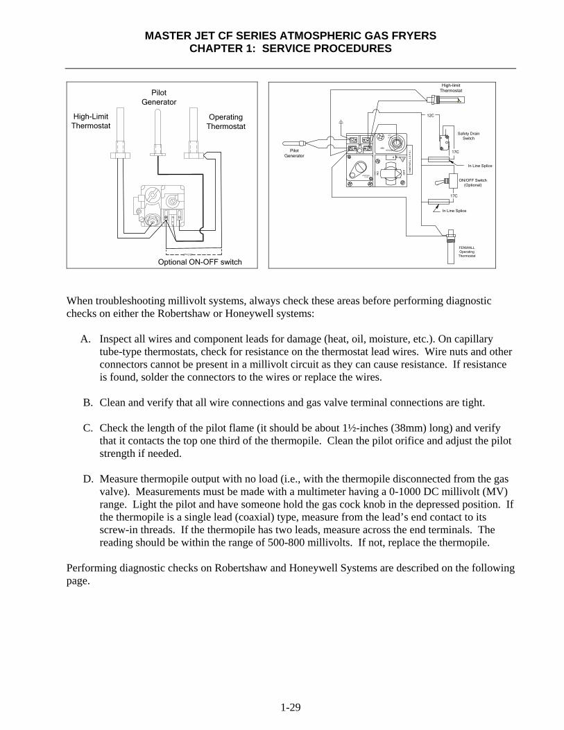
When troubleshooting millivolt systems, always check these areas before performing diagnostic checks on either the Robertshaw or Honeywell systems: A. Inspect all wires and component leads for damage (heat, oil, moisture, etc.). On capillary
tube-type thermostats, check for resistance on the thermostat lead wires. Wire nuts and other connectors cannot be present in a millivolt circuit as they can cause resistance. If resistance is found, solder the connectors to the wires or replace the wires.
B. Clean and verify that all wire connections and gas valve terminal connections are tight.
C. Check the length of the pilot flame (it should be about 1½-inches (38mm) long) and verify
that it contacts the top one third of the thermopile. Clean the pilot orifice and adjust the pilot strength if needed.
D. Measure thermopile output with no load (i.e., with the thermopile disconnected from the gas
valve). Measurements must be made with a multimeter having a 0-1000 DC millivolt (MV) range. Light the pilot and have someone hold the gas cock knob in the depressed position. If the thermopile is a single lead (coaxial) type, measure from the lead’s end contact to its screw-in threads. If the thermopile has two leads, measure across the end terminals. The reading should be within the range of 500-800 millivolts. If not, replace the thermopile.
Performing diagnostic checks on Robertshaw and Honeywell Systems are described on the following page.
MASTER JET CF SERIES ATMOSPHERIC GAS FRYERS
CHAPTER 1: SERVICE PROCEDURES
1-30
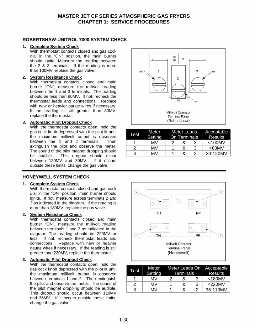
ROBERTSHAW-UNITROL 7000 SYSTEM CHECK
1. Complete System Check With thermostat contacts closed and gas cock
dial in the “ON” position, the main burner should ignite. Measure the reading between the 2 & 3 terminals. If the reading is more than 100MV, replace the gas valve.
2. System Resistance Check With thermostat contacts closed and main
burner “ON”, measure the millivolt reading between the 1 and 3 terminals. The reading should be less than 80MV. If not, recheck the thermostat leads and connections. Replace with new or heavier gauge wires if necessary. If the reading is still greater than 80MV, replace the thermostat.
3. Automatic Pilot Dropout Check With the thermostat contacts open, hold the gas cock knob depressed with the pilot lit until the maximum millivolt output is observed between the 1 and 2 terminals. Then extinguish the pilot and observe the meter. The sound of the pilot magnet dropping should be audible. This dropout should occur between 120MV and 30MV. If it occurs outside these limits, change the gas valve.
THTP TH
TP TP
THTP TH
Millivolt OperatorTerminal Panel(Robertshaw)
1
2
3
Test Meter Setting
Meter Leads On Terminals
Acceptable Results
1 MV 2 & 3 <100MV 2 MV 1 & 3 <80MV 3 MV 1 & 2 30-120MV
HONEYWELL SYSTEM CHECK
1. Complete System Check With thermostat contacts closed and gas cock
dial in the “ON” position, main burner should ignite. If not, measure across terminals 2 and 3 as indicated in the diagram. If the reading is more than 180MV, replace the gas valve.
2. System Resistance Check With thermostat contacts closed and main
burner “ON”, measure the millivolt reading between terminals 1 and 3 as indicated in the diagram. The reading should be 220MV or less. If not, recheck thermostat leads and connections. Replace with new or heavier gauge wires if necessary. If the reading is still greater than 220MV, replace the thermostat.
3. Automatic Pilot Dropout Check With the thermostat contacts open, hold the gas cock knob depressed with the pilot lit until the maximum millivolt output is observed between terminals 1 and 2. Then extinguish the pilot and observe the meter. The sound of the pilot magnet dropping should be audible. This dropout should occur between 110MV and 36MV. If it occurs outside these limits, change the gas valve.
TH
TH PP
PP
4
3
1
2
Millivolt OperatorTerminal Panel(Honeywell)
Test Meter Setting
Meter Leads On Terminals
Acceptable Results
1 MV 2 & 3 <180MV 2 MV 1 & 3 <220MV 3 MV 1 & 2 36-110MV
MASTER JET CF SERIES ATMOSPHERIC GAS FRYERS CHAPTER 1: SERVICE PROCEDURES
1-31
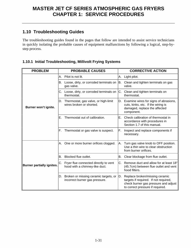
1.10 Troubleshooting Guides The troubleshooting guides found in the pages that follow are intended to assist service technicians in quickly isolating the probable causes of equipment malfunctions by following a logical, step-by-step process. 1.10.1 Initial Troubleshooting, Millivolt Frying Systems
PROBLEM PROBABLE CAUSES CORRECTIVE ACTION
Burner won’t ignite.
A. Pilot is not lit. A. Light pilot.
B. Loose, dirty, or corroded terminals on gas valve.
B. Clean and tighten terminals on gas valve.
C. Loose, dirty, or corroded terminals on thermostat.
C. Clean and tighten terminals on thermostat.
D. Thermostat, gas valve, or high-limit wires broken or shorted.
D. Examine wires for signs of abrasions, cuts, kinks, etc. If the wiring is damaged, replace the affected component.
E. Thermostat out of calibration. E. Check calibration of thermostat in accordance with procedures in Section 1.7 of this manual.
F. Thermostat or gas valve is suspect. F. Inspect and replace components if necessary.
Burner partially ignites.
A. One or more burner orifices clogged. A. Turn gas valve knob to OFF position. Use a thin wire to clear obstruction from burner orifices.
B. Blocked flue outlet. B. Clear blockage from flue outlet.
C. Fryer flue connected directly to vent hood with a chimney-like duct.
C. Remove duct and allow for at least 18" (45.7cm) between flue outlet and vent hood filters.
D. Broken or missing ceramic targets, or incorrect burner gas pressure.
D. Replace broken/missing ceramic targets if required. If not required, check burner gas pressure and adjust to correct pressure if required.
MASTER JET CF SERIES ATMOSPHERIC GAS FRYERS
CHAPTER 1: SERVICE PROCEDURES
1-32
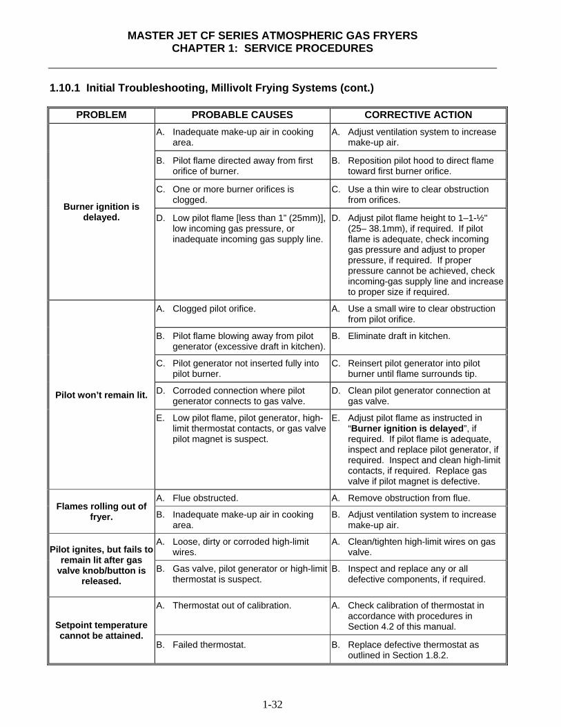
1.10.1 Initial Troubleshooting, Millivolt Frying Systems (cont.)
PROBLEM PROBABLE CAUSES CORRECTIVE ACTION
Burner ignition is delayed.
A. Inadequate make-up air in cooking area.
A. Adjust ventilation system to increase make-up air.
B. Pilot flame directed away from first orifice of burner.
B. Reposition pilot hood to direct flame toward first burner orifice.
C. One or more burner orifices is clogged.
C. Use a thin wire to clear obstruction from orifices.
D. Low pilot flame [less than 1” (25mm)], low incoming gas pressure, or inadequate incoming gas supply line.
D. Adjust pilot flame height to 1–1-½" (25– 38.1mm), if required. If pilot flame is adequate, check incoming gas pressure and adjust to proper pressure, if required. If proper pressure cannot be achieved, check incoming-gas supply line and increase to proper size if required.
Pilot won’t remain lit.
A. Clogged pilot orifice. A. Use a small wire to clear obstruction from pilot orifice.
B. Pilot flame blowing away from pilot generator (excessive draft in kitchen).
B. Eliminate draft in kitchen.
C. Pilot generator not inserted fully into pilot burner.
C. Reinsert pilot generator into pilot burner until flame surrounds tip.
D. Corroded connection where pilot generator connects to gas valve.
D. Clean pilot generator connection at gas valve.
E. Low pilot flame, pilot generator, high-limit thermostat contacts, or gas valve pilot magnet is suspect.
E. Adjust pilot flame as instructed in “Burner ignition is delayed”, if required. If pilot flame is adequate, inspect and replace pilot generator, if required. Inspect and clean high-limit contacts, if required. Replace gas valve if pilot magnet is defective.
Flames rolling out of fryer.
A. Flue obstructed. A. Remove obstruction from flue.
B. Inadequate make-up air in cooking area.
B. Adjust ventilation system to increase make-up air.
Pilot ignites, but fails to
remain lit after gas valve knob/button is
released.
A. Loose, dirty or corroded high-limit wires.
A. Clean/tighten high-limit wires on gas valve.
B. Gas valve, pilot generator or high-limit thermostat is suspect.
B. Inspect and replace any or all defective components, if required.
Setpoint temperature cannot be attained.
A. Thermostat out of calibration. A. Check calibration of thermostat in accordance with procedures in Section 4.2 of this manual.
B. Failed thermostat. B. Replace defective thermostat as outlined in Section 1.8.2.
MASTER JET CF SERIES ATMOSPHERIC GAS FRYERS
CHAPTER 1: SERVICE PROCEDURES
1-33
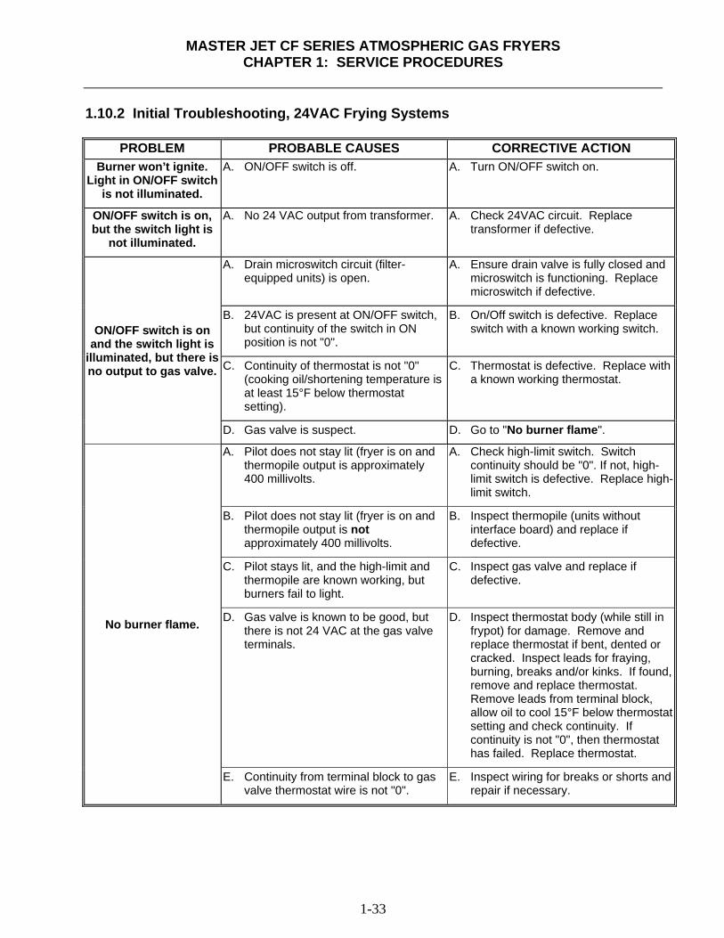
1.10.2 Initial Troubleshooting, 24VAC Frying Systems
PROBLEM PROBABLE CAUSES CORRECTIVE ACTION Burner won’t ignite.
Light in ON/OFF switch is not illuminated.
A. ON/OFF switch is off. A. Turn ON/OFF switch on.
ON/OFF switch is on, but the switch light is
not illuminated.
A. No 24 VAC output from transformer. A. Check 24VAC circuit. Replace transformer if defective.
ON/OFF switch is on and the switch light is
illuminated, but there is no output to gas valve.
A. Drain microswitch circuit (filter-equipped units) is open.
A. Ensure drain valve is fully closed and microswitch is functioning. Replace microswitch if defective.
B. 24VAC is present at ON/OFF switch, but continuity of the switch in ON position is not "0".
B. On/Off switch is defective. Replace switch with a known working switch.
C. Continuity of thermostat is not "0" (cooking oil/shortening temperature is at least 15°F below thermostat setting).
C. Thermostat is defective. Replace with a known working thermostat.
D. Gas valve is suspect. D. Go to "No burner flame".
No burner flame.
A. Pilot does not stay lit (fryer is on and thermopile output is approximately 400 millivolts.
A. Check high-limit switch. Switch continuity should be "0". If not, high-limit switch is defective. Replace high-limit switch.
B. Pilot does not stay lit (fryer is on and thermopile output is not approximately 400 millivolts.
B. Inspect thermopile (units without interface board) and replace if defective.
C. Pilot stays lit, and the high-limit and thermopile are known working, but burners fail to light.
C. Inspect gas valve and replace if defective.
D. Gas valve is known to be good, but there is not 24 VAC at the gas valve terminals.
D. Inspect thermostat body (while still in frypot) for damage. Remove and replace thermostat if bent, dented or cracked. Inspect leads for fraying, burning, breaks and/or kinks. If found, remove and replace thermostat. Remove leads from terminal block, allow oil to cool 15°F below thermostat setting and check continuity. If continuity is not "0", then thermostat has failed. Replace thermostat.
E. Continuity from terminal block to gas valve thermostat wire is not "0".
E. Inspect wiring for breaks or shorts and repair if necessary.
MASTER JET CF SERIES ATMOSPHERIC GAS FRYERS
CHAPTER 1: SERVICE PROCEDURES
1-34
1.10.2 Initial Troubleshooting, 24VAC Frying Systems (cont.)
PROBLEM PROBABLE CAUSE CORRECTIVE ACTION
Fluctuating or erratic lighting of burner
flame.
A. Incoming gas supply pressures are not within range [Natural- 6-14" W.C. (1.49-3.49 kPa); Propane- 11-14" W.C. (2.74-3.49 kPa)]
A. Inspect gas supply to fryer. Repair and/or replace faulty components (defective supply shut-off valves, incorrect piping size, etc.)
B. Air in gas supply lines (new installation).
B. Allow unit to cycle on and off for approximately 30 minutes to force air from gas manifold and lines.
C. Missing or poor target alignment. C. Replace missing target(s) and/or ensure correct target alignment.
Thermostat will not adjust to correct
temperature.
A. Thermostat is out of calibration. A. Calibrate thermostat. Replace thermostat if calibration is not possible.
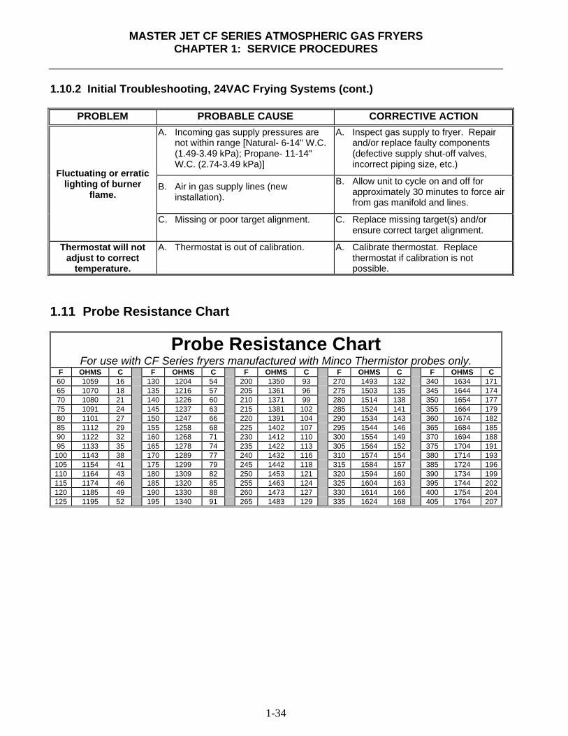
1.11 Probe Resistance Chart
Probe Resistance Chart For use with CF Series fryers manufactured with Minco Thermistor probes only.
F OHMS C F OHMS C F OHMS C F OHMS C F OHMS C 60 1059 16 130 1204 54 200 1350 93 270 1493 132 340 1634 17165 1070 18 135 1216 57 205 1361 96 275 1503 135 345 1644 17470 1080 21 140 1226 60 210 1371 99 280 1514 138 350 1654 17775 1091 24 145 1237 63 215 1381 102 285 1524 141 355 1664 17980 1101 27 150 1247 66 220 1391 104 290 1534 143 360 1674 18285 1112 29 155 1258 68 225 1402 107 295 1544 146 365 1684 18590 1122 32 160 1268 71 230 1412 110 300 1554 149 370 1694 18895 1133 35 165 1278 74 235 1422 113 305 1564 152 375 1704 191
100 1143 38 170 1289 77 240 1432 116 310 1574 154 380 1714 193105 1154 41 175 1299 79 245 1442 118 315 1584 157 385 1724 196110 1164 43 180 1309 82 250 1453 121 320 1594 160 390 1734 199115 1174 46 185 1320 85 255 1463 124 325 1604 163 395 1744 202120 1185 49 190 1330 88 260 1473 127 330 1614 166 400 1754 204125 1195 52 195 1340 91 265 1483 129 335 1624 168 405 1764 207
MASTER JET CF SERIES ATMOSPHERIC GAS FRYERS
CHAPTER 1: SERVICE PROCEDURES
1-35
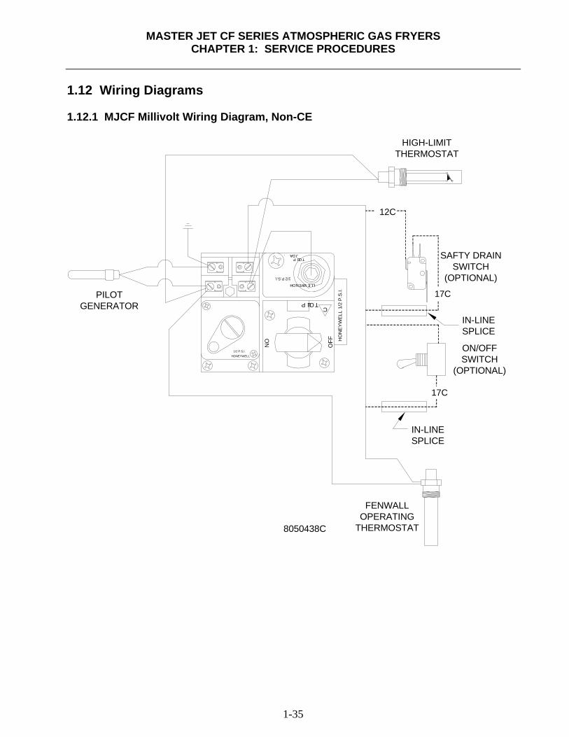
1.12 Wiring Diagrams 1.12.1 MJCF Millivolt Wiring Diagram, Non-CE
8050438C
HO
NE
YWEL
L 1/
2 P
.S.I.
1/2 P.S.I.HONEYWELL
OFF
ON
PILOTC
HONEYWELL
1/2 P.S.I.
ADJ.PILOT
17C
17C
12C
PILOT GENERATOR
HIGH-LIMIT THERMOSTAT
SAFTY DRAIN SWITCH
(OPTIONAL)
IN-LINE SPLICE
ON/OFF SWITCH
(OPTIONAL)
FENWALL OPERATING
THERMOSTAT
IN-LINE SPLICE
MASTER JET CF SERIES ATMOSPHERIC GAS FRYERS
CHAPTER 1: SERVICE PROCEDURES
1-36
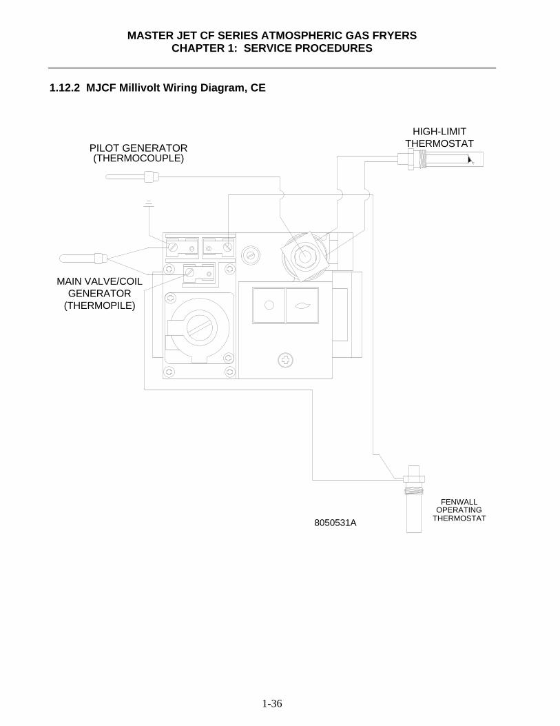
1.12.2 MJCF Millivolt Wiring Diagram, CE
FENWALLOPERATING
THERMOSTAT8050531A
PILOT GENERATOR(THERMOCOUPLE)
MAIN VALVE/COILGENERATOR
(THERMOPILE)
HIGH-LIMITTHERMOSTAT
MASTER JET CF SERIES ATMOSPHERIC GAS FRYERS
CHAPTER 1: SERVICE PROCEDURES
1-37
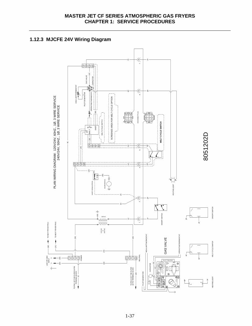
1.12.3 MJCFE 24V Wiring Diagram
24 VAC
7P
or24
0 V
AC
6C C
2
1
6P1/2
P.S
.I.
HO
NE
YWE
LL
ON
PILO
THO
NE
YW
ELL
1/2 P.S
.I.
11C
AD
J.P
ILOT
5P
4P
OFF
22C
12C
5 876
24C
27C
1P
2P
2
1
1P
1
1C
2P
2
2C
4
4P4C
2C
20C
120
VAC
22C
1C4
27C
1 32
23C
NH
25C
26C
10C
C
12C
NC
NO
1614 1513
8051
202D
5C 5P
5
7 4 1
98
6 3
5 2
4 7
6 9
5 8
6
13
2
7C 7P6P6C
7
VALVE
GN
D
17 19 2018
14C
MEL
T13
C24
V
9C
50C
1111
C
12109
PLAN
WIR
ING
DIA
GR
AM:
120V
/24V
, 60H
Z., 1
Ø, 3
WIR
E SE
RVI
CE
2
40V/
24V,
50H
Z., 1
Ø, 3
WIR
E SE
RVI
CE
TO N
EX
T FR
YE
R P
IN 2
TO N
EX
T FR
YE
R P
IN 6
120V
OR
240
VIN
PU
T
TO P
IN 1
OF
THE
FIL
TER
16
PIN
TER
MIN
AL
BLO
CK
PO
WE
R
TO P
IN 1
3 O
F TH
E F
ILTE
R16
PIN
TE
RM
INA
L BL
OC
K
NE
UTR
AL
HIG
H-L
IMIT
THE
RM
OS
TAT
GAS
VAL
VE
OP
ER
ATI
NG
TH
ER
MO
STA
T
ON
/OFF
SW
ITC
H
HE
ATI
NG
LIG
HT
ON
/OFF
SW
ITC
HM
ELT
CY
CLE
SW
ITC
HH
EA
TIN
G L
IGH
T
PIL
OT
GE
NE
RA
TOR
MEL
T C
YCLE
SW
ITC
H
ME
LT C
YC
LE S
WIT
CH
DIS
CO
NN
EC
T P
LUG
SOU
ND
DEV
ICE
SAF
ETY
DR
AIN
OPT
ION
CA
PA
CIT
OR
HONEYWELL 1/2 PSI
OP
ER
ATI
NG
TH
ER
MO
STA
T
GA
S V
ALV
E
CA
PA
CIT
OR
HIG
H-L
IMIT
THE
RM
OS
TAT
PIL
OT
GE
NE
RA
TOR
SC
RE
EN
ED
AR
EA
FO
R M
ELT
CY
CLE
OP
TIO
N
MASTER JET CF SERIES ATMOSPHERIC GAS FRYERS
CHAPTER 1: SERVICE PROCEDURES
1-38
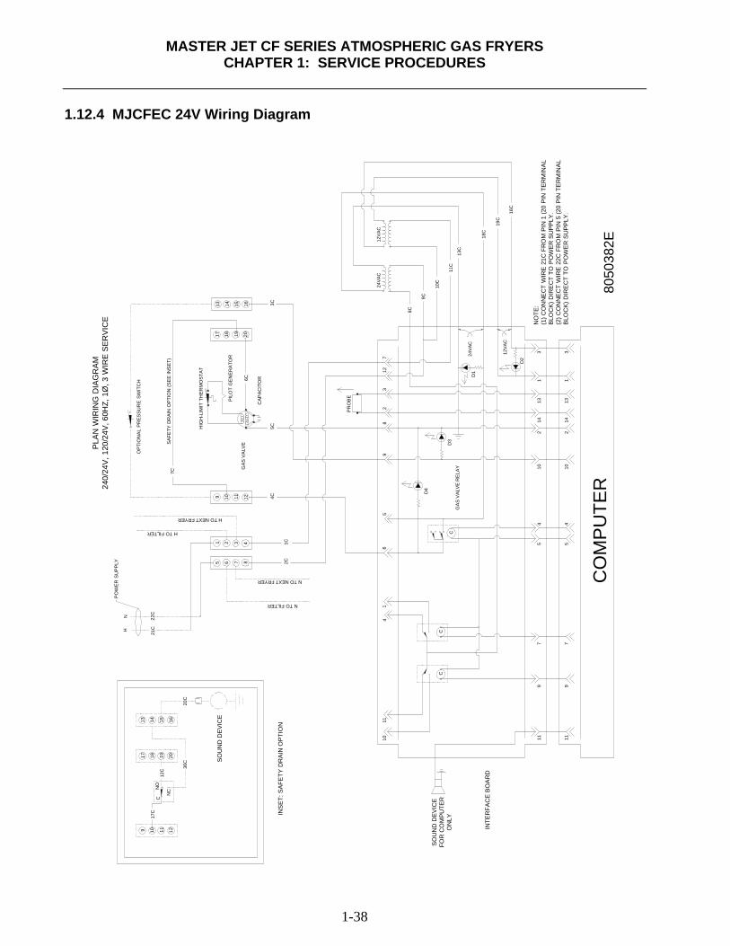
1.12.4 MJCFEC 24V Wiring Diagram
12V
AC
11 11
104
57
9 97
45
10
CC
C
D4
31
132
14
214
113
324V
AC
12VA
C
D2
D1
D3
18C
10C
9C
8C
11C
13C
1011
41
65
2C1C
7 8
3 4
4C11 12
NH
21C
22C
5 6
1 2
9 10
7C
92
83
712
5C
6C
24VA
C
3C
19 20
15 16
17 18
13 14
16C
19C
PO
WER
SU
PPL
Y
NO
TE:
(1) C
ON
NE
CT
WIR
E 2
1C F
RO
M P
IN 1
(20
PIN
TER
MIN
AL
BLO
CK)
DIR
EC
T TO
PO
WE
R S
UP
PLY
.(2
) CO
NN
EC
T W
IRE
22C
FR
OM
PIN
5 (2
0 P
IN T
ERM
INA
LB
LOC
K) D
IRE
CT
TO P
OW
ER
SU
PP
LY.
8050
382E
CO
MPU
TER
INTE
RFA
CE
BO
AR
D
SO
UN
D D
EV
ICE
FOR
CO
MP
UTE
RO
NLY17
C
9 10 1211
36C
20C
17 18 2019N
OC
NC
12C
13 14 1615
INS
ET:
SA
FETY
DR
AIN
OP
TIO
N
SO
UN
D D
EVI
CE
PLA
N W
IRIN
G D
IAG
RA
M24
0/24
V, 1
20/2
4V, 6
0HZ,
1Ø
, 3 W
IRE
SE
RV
ICE
SAF
ETY
DR
AIN
OPT
ION
(SE
E IN
SET)
OPT
ION
AL P
RES
SUR
E SW
ITC
H
CAP
ACIT
OR
GAS
VAL
VE
HIG
H-L
IMIT
TH
ERM
OS
TAT
H TO FILTER
H TO NEXT FRYER
N TO FILTER
N TO NEXT FRYER
GAS
VAL
VE
RE
LAY
PRO
BEPILO
T G
EN
ER
ATO
R
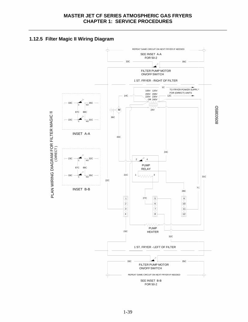
MASTER JET CF SERIES ATMOSPHERIC GAS FRYERS
CHAPTER 1: SERVICE PROCEDURES
1-39
1.12.5 Filter Magic II Wiring Diagram
FOR (DIRECT) UNITS100V200V
OR220V
120V208V
35C
12
32C
HEATERPUMP
8
7C
9
10
28C
31C
5
6
3
7 11
33C
4
23C
8050
385D
1
2
121C
22CNO
88C
35C
3
C
87C
33C
INSET B-B
REPEAT SAME CIRCUIT ON NEXT FRYER IF NEEDED
FILTER PUMP MOTOR
27C
1 ST. FRYER - LEFT OF FILTER
ON/OFF SWITCH
PUMPRELAY
SEE INSET B-BFOR 50-2
24C
24V
240V
1C
230V 12C
TO FRYER POWER SUPPLY
35C
2
43C
32CNO
NO
M
14C
88C
35CNO
36C31C
C23C
C
87C
C33C
22C
INSET A-A
33C
FILTER PUMP MOTOR
REPEAT SAME CIRCUIT ON NEXT FRYER IF NEEDED
4
ON/OFF SWITCH
1 ST. FRYER - RIGHT OF FILTER
FOR 50-2SEE INSET A-A
( DIR
ECT
)P
LAN
WIR
ING
DIA
GR
AM
FO
R F
ILTE
R M
AGIC
II
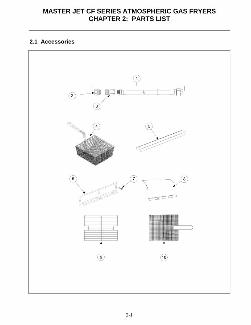
MASTER JET CF SERIES ATMOSPHERIC GAS FRYERS CHAPTER 2: PARTS LIST
2-1
2.1 Accessories
1
2
3
4 5
6 7 8
9 10
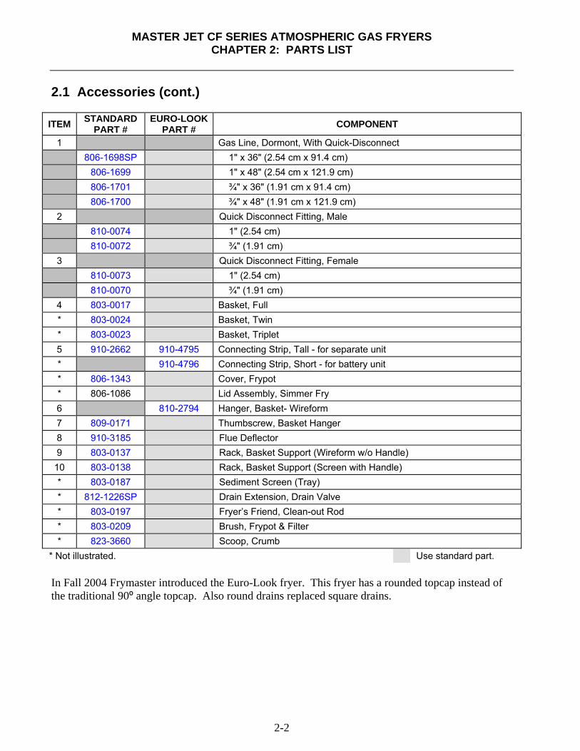
MASTER JET CF SERIES ATMOSPHERIC GAS FRYERS
CHAPTER 2: PARTS LIST
2-2
2.1 Accessories (cont.)
ITEM STANDARDPART #
EURO-LOOK PART # COMPONENT
1 Gas Line, Dormont, With Quick-Disconnect 806-1698SP 1" x 36" (2.54 cm x 91.4 cm) 806-1699 1" x 48" (2.54 cm x 121.9 cm) 806-1701 ¾" x 36" (1.91 cm x 91.4 cm) 806-1700 ¾" x 48" (1.91 cm x 121.9 cm)
2 Quick Disconnect Fitting, Male 810-0074 1" (2.54 cm) 810-0072 ¾" (1.91 cm)
3 Quick Disconnect Fitting, Female 810-0073 1" (2.54 cm) 810-0070 ¾" (1.91 cm)
4 803-0017 Basket, Full * 803-0024 Basket, Twin * 803-0023 Basket, Triplet 5 910-2662 910-4795 Connecting Strip, Tall - for separate unit * 910-4796 Connecting Strip, Short - for battery unit * 806-1343 Cover, Frypot * 806-1086 Lid Assembly, Simmer Fry 6 810-2794 Hanger, Basket- Wireform 7 809-0171 Thumbscrew, Basket Hanger 8 910-3185 Flue Deflector 9 803-0137 Rack, Basket Support (Wireform w/o Handle) 10 803-0138 Rack, Basket Support (Screen with Handle) * 803-0187 Sediment Screen (Tray) * 812-1226SP Drain Extension, Drain Valve * 803-0197 Fryer’s Friend, Clean-out Rod * 803-0209 Brush, Frypot & Filter * 823-3660 Scoop, Crumb
* Not illustrated. Use standard part. In Fall 2004 Frymaster introduced the Euro-Look fryer. This fryer has a rounded topcap instead of the traditional 90º angle topcap. Also round drains replaced square drains.
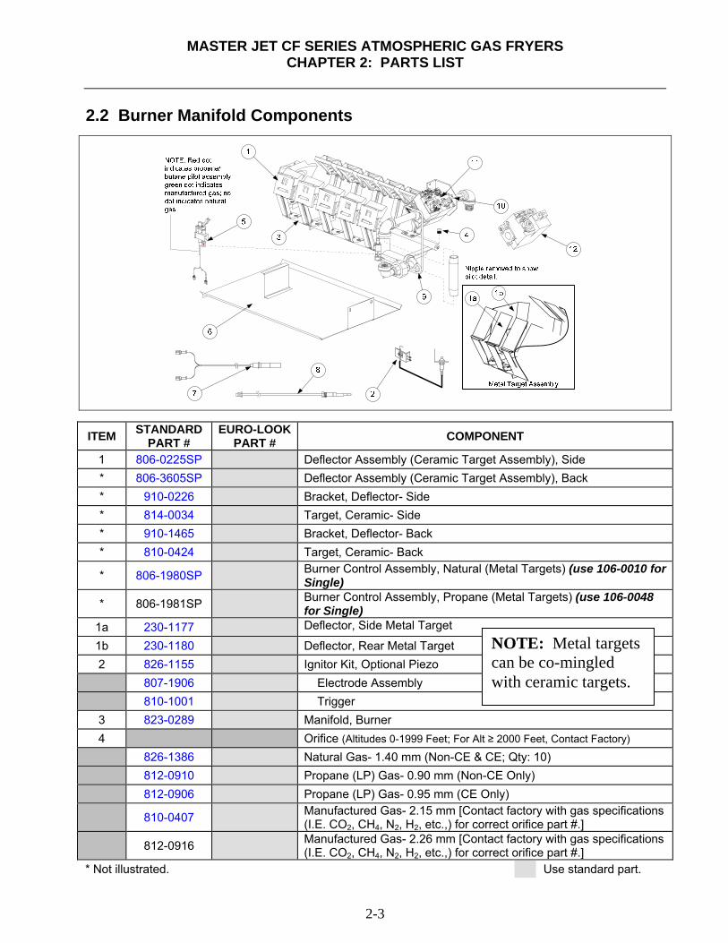
MASTER JET CF SERIES ATMOSPHERIC GAS FRYERS
CHAPTER 2: PARTS LIST
2-3
2.2 Burner Manifold Components
ITEM STANDARD PART #
EURO-LOOK PART # COMPONENT
1 806-0225SP Deflector Assembly (Ceramic Target Assembly), Side * 806-3605SP Deflector Assembly (Ceramic Target Assembly), Back * 910-0226 Bracket, Deflector- Side * 814-0034 Target, Ceramic- Side * 910-1465 Bracket, Deflector- Back * 810-0424 Target, Ceramic- Back
* 806-1980SP Burner Control Assembly, Natural (Metal Targets) (use 106-0010 for Single)
* 806-1981SP Burner Control Assembly, Propane (Metal Targets) (use 106-0048 for Single)
1a 230-1177 Deflector, Side Metal Target
1b 230-1180 Deflector, Rear Metal Target 2 826-1155 Ignitor Kit, Optional Piezo 807-1906 Electrode Assembly 810-1001 Trigger 3 823-0289 Manifold, Burner 4 Orifice (Altitudes 0-1999 Feet; For Alt ≥ 2000 Feet, Contact Factory) 826-1386 Natural Gas- 1.40 mm (Non-CE & CE; Qty: 10) 812-0910 Propane (LP) Gas- 0.90 mm (Non-CE Only) 812-0906 Propane (LP) Gas- 0.95 mm (CE Only)
810-0407 Manufactured Gas- 2.15 mm [Contact factory with gas specifications (I.E. CO2, CH4, N2, H2, etc.,) for correct orifice part #.]
812-0916 Manufactured Gas- 2.26 mm [Contact factory with gas specifications (I.E. CO2, CH4, N2, H2, etc.,) for correct orifice part #.]
* Not illustrated. Use standard part.
NOTE: Metal targets can be co-mingled with ceramic targets.
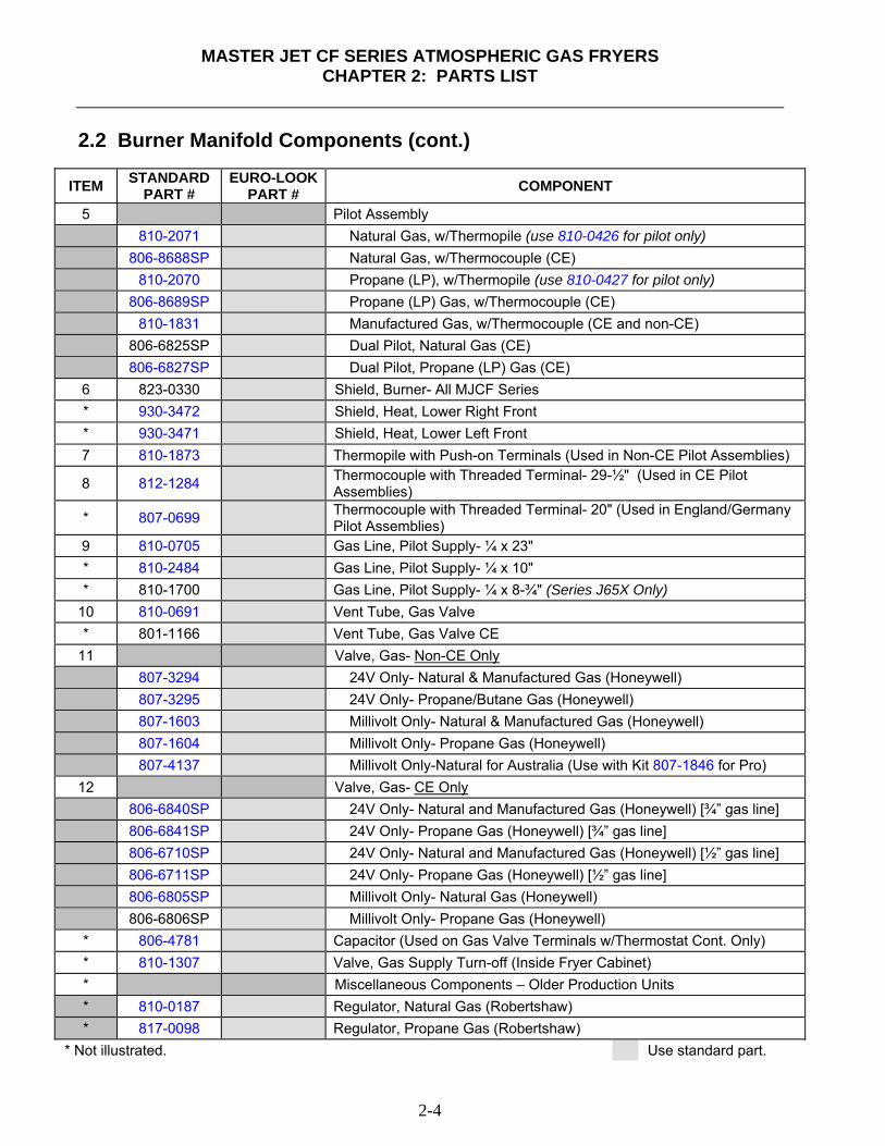
MASTER JET CF SERIES ATMOSPHERIC GAS FRYERS
CHAPTER 2: PARTS LIST
2-4
2.2 Burner Manifold Components (cont.)
ITEM STANDARD PART #
EURO-LOOK PART # COMPONENT
5 Pilot Assembly 810-2071 Natural Gas, w/Thermopile (use 810-0426 for pilot only) 806-8688SP Natural Gas, w/Thermocouple (CE) 810-2070 Propane (LP), w/Thermopile (use 810-0427 for pilot only) 806-8689SP Propane (LP) Gas, w/Thermocouple (CE) 810-1831 Manufactured Gas, w/Thermocouple (CE and non-CE) 806-6825SP Dual Pilot, Natural Gas (CE) 806-6827SP Dual Pilot, Propane (LP) Gas (CE)
6 823-0330 Shield, Burner- All MJCF Series * 930-3472 Shield, Heat, Lower Right Front * 930-3471 Shield, Heat, Lower Left Front 7 810-1873 Thermopile with Push-on Terminals (Used in Non-CE Pilot Assemblies)
8 812-1284 Thermocouple with Threaded Terminal- 29-½" (Used in CE Pilot Assemblies)
* 807-0699 Thermocouple with Threaded Terminal- 20" (Used in England/Germany Pilot Assemblies)
9 810-0705 Gas Line, Pilot Supply- ¼ x 23" * 810-2484 Gas Line, Pilot Supply- ¼ x 10" * 810-1700 Gas Line, Pilot Supply- ¼ x 8-¾" (Series J65X Only)
10 810-0691 Vent Tube, Gas Valve * 801-1166 Vent Tube, Gas Valve CE
11 Valve, Gas- Non-CE Only 807-3294 24V Only- Natural & Manufactured Gas (Honeywell) 807-3295 24V Only- Propane/Butane Gas (Honeywell) 807-1603 Millivolt Only- Natural & Manufactured Gas (Honeywell) 807-1604 Millivolt Only- Propane Gas (Honeywell) 807-4137 Millivolt Only-Natural for Australia (Use with Kit 807-1846 for Pro)
12 Valve, Gas- CE Only 806-6840SP 24V Only- Natural and Manufactured Gas (Honeywell) [¾” gas line] 806-6841SP 24V Only- Propane Gas (Honeywell) [¾” gas line] 806-6710SP 24V Only- Natural and Manufactured Gas (Honeywell) [½” gas line] 806-6711SP 24V Only- Propane Gas (Honeywell) [½” gas line] 806-6805SP Millivolt Only- Natural Gas (Honeywell) 806-6806SP Millivolt Only- Propane Gas (Honeywell) * 806-4781 Capacitor (Used on Gas Valve Terminals w/Thermostat Cont. Only) * 810-1307 Valve, Gas Supply Turn-off (Inside Fryer Cabinet) * Miscellaneous Components – Older Production Units * 810-0187 Regulator, Natural Gas (Robertshaw) * 817-0098 Regulator, Propane Gas (Robertshaw)
* Not illustrated. Use standard part.
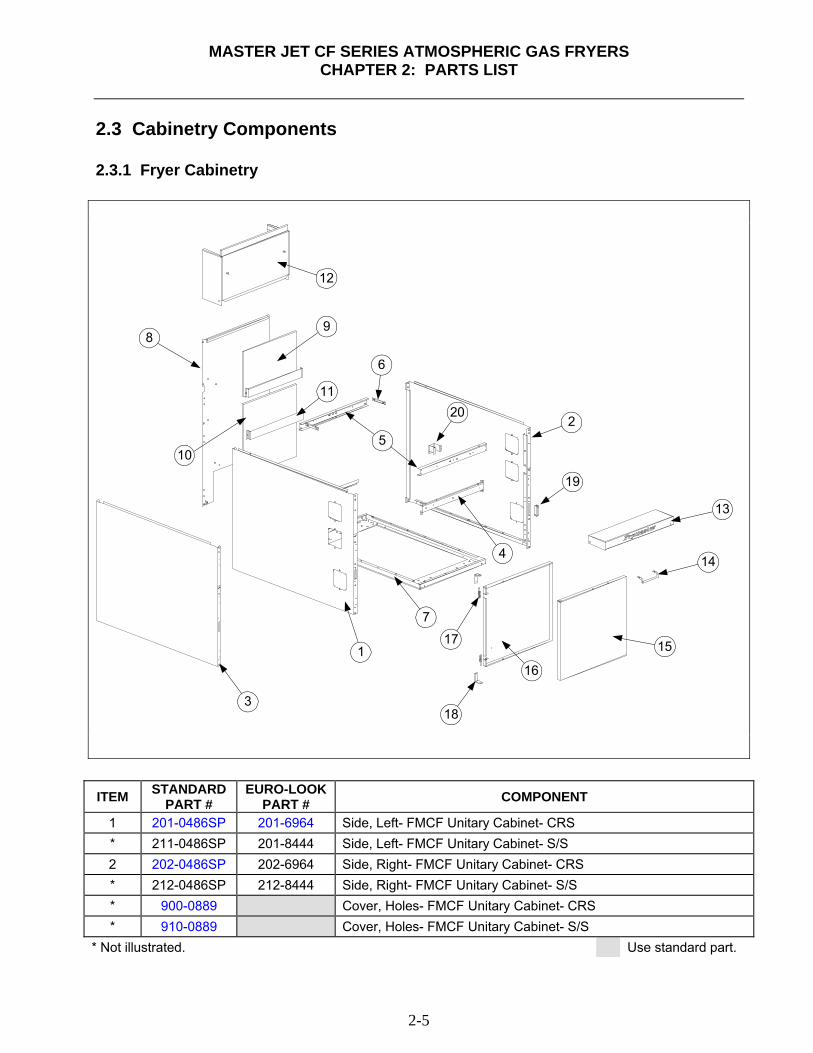
MASTER JET CF SERIES ATMOSPHERIC GAS FRYERS
CHAPTER 2: PARTS LIST
2-5
2.3 Cabinetry Components 2.3.1 Fryer Cabinetry
1
3
2
4
6
7
89
10
11
12
13
14
15
16
17
18
5
19
20
ITEM STANDARD
PART # EURO-LOOK
PART # COMPONENT
1 201-0486SP 201-6964 Side, Left- FMCF Unitary Cabinet- CRS * 211-0486SP 201-8444 Side, Left- FMCF Unitary Cabinet- S/S 2 202-0486SP 202-6964 Side, Right- FMCF Unitary Cabinet- CRS * 212-0486SP 212-8444 Side, Right- FMCF Unitary Cabinet- S/S * 900-0889 Cover, Holes- FMCF Unitary Cabinet- CRS * 910-0889 Cover, Holes- FMCF Unitary Cabinet- S/S
* Not illustrated. Use standard part.
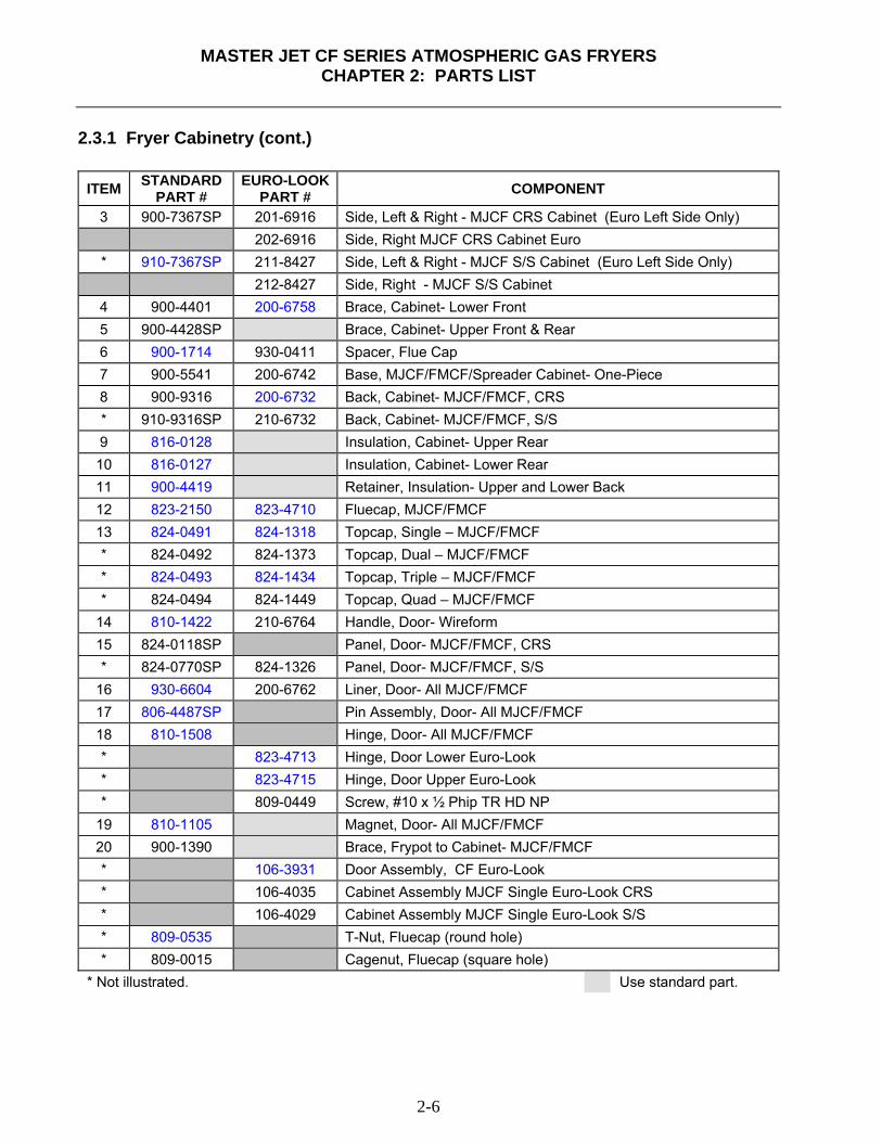
MASTER JET CF SERIES ATMOSPHERIC GAS FRYERS
CHAPTER 2: PARTS LIST
2-6
2.3.1 Fryer Cabinetry (cont.)
ITEM STANDARD PART #
EURO-LOOK PART # COMPONENT
3 900-7367SP 201-6916 Side, Left & Right - MJCF CRS Cabinet (Euro Left Side Only) 202-6916 Side, Right MJCF CRS Cabinet Euro * 910-7367SP 211-8427 Side, Left & Right - MJCF S/S Cabinet (Euro Left Side Only) 212-8427 Side, Right - MJCF S/S Cabinet
4 900-4401 200-6758 Brace, Cabinet- Lower Front 5 900-4428SP Brace, Cabinet- Upper Front & Rear 6 900-1714 930-0411 Spacer, Flue Cap 7 900-5541 200-6742 Base, MJCF/FMCF/Spreader Cabinet- One-Piece 8 900-9316 200-6732 Back, Cabinet- MJCF/FMCF, CRS * 910-9316SP 210-6732 Back, Cabinet- MJCF/FMCF, S/S 9 816-0128 Insulation, Cabinet- Upper Rear 10 816-0127 Insulation, Cabinet- Lower Rear 11 900-4419 Retainer, Insulation- Upper and Lower Back 12 823-2150 823-4710 Fluecap, MJCF/FMCF 13 824-0491 824-1318 Topcap, Single – MJCF/FMCF * 824-0492 824-1373 Topcap, Dual – MJCF/FMCF * 824-0493 824-1434 Topcap, Triple – MJCF/FMCF * 824-0494 824-1449 Topcap, Quad – MJCF/FMCF
14 810-1422 210-6764 Handle, Door- Wireform 15 824-0118SP Panel, Door- MJCF/FMCF, CRS * 824-0770SP 824-1326 Panel, Door- MJCF/FMCF, S/S
16 930-6604 200-6762 Liner, Door- All MJCF/FMCF 17 806-4487SP Pin Assembly, Door- All MJCF/FMCF 18 810-1508 Hinge, Door- All MJCF/FMCF * 823-4713 Hinge, Door Lower Euro-Look * 823-4715 Hinge, Door Upper Euro-Look * 809-0449 Screw, #10 x ½ Phip TR HD NP
19 810-1105 Magnet, Door- All MJCF/FMCF 20 900-1390 Brace, Frypot to Cabinet- MJCF/FMCF * 106-3931 Door Assembly, CF Euro-Look * 106-4035 Cabinet Assembly MJCF Single Euro-Look CRS * 106-4029 Cabinet Assembly MJCF Single Euro-Look S/S * 809-0535 T-Nut, Fluecap (round hole) * 809-0015 Cagenut, Fluecap (square hole)
* Not illustrated. Use standard part.
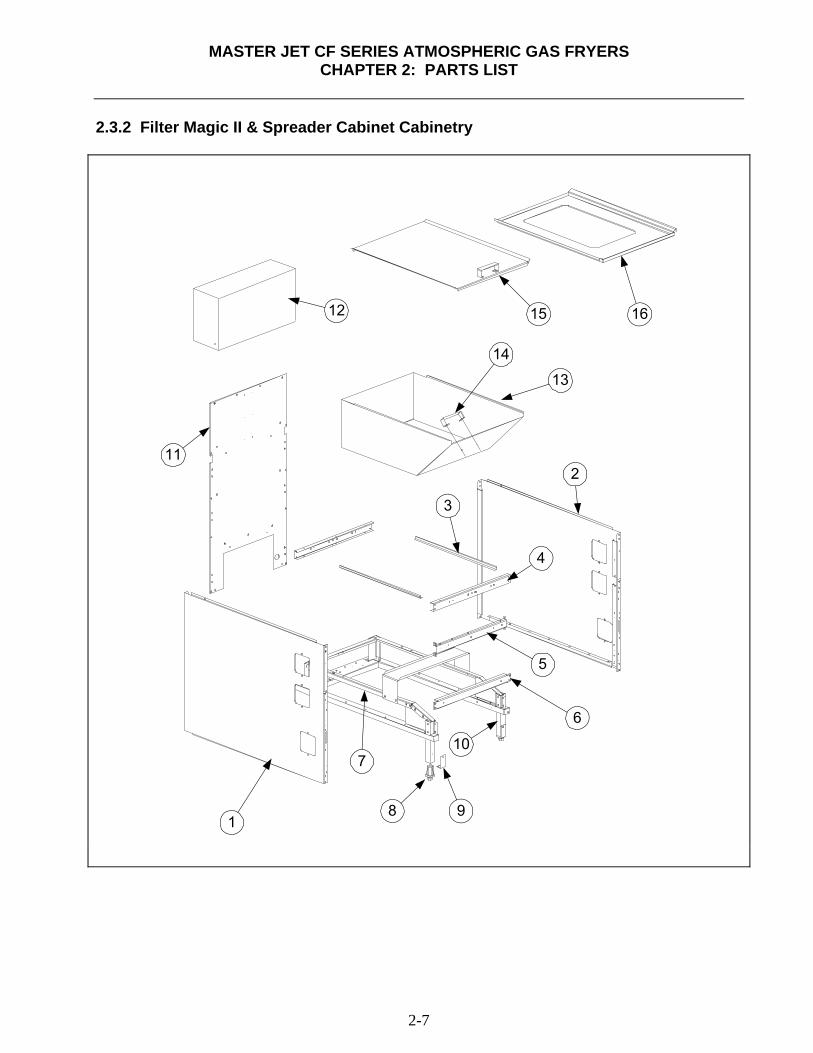
MASTER JET CF SERIES ATMOSPHERIC GAS FRYERS
CHAPTER 2: PARTS LIST
2-7
2.3.2 Filter Magic II & Spreader Cabinet Cabinetry
1
2
3
4
5
6
7
8 9
10
11
12
13
15
14
16

MASTER JET CF SERIES ATMOSPHERIC GAS FRYERS
CHAPTER 2: PARTS LIST
2-8
2.3.2 Filter Magic & Spreader Cabinet Cabinetry (cont.)
ITEM STANDARD PART #
EURO-LOOK PART # COMPONENT
1 201-0486SP 201-6964 Side, Left- Filter Magic/Spreader Cabinet- CRS * 211-0486SP 211-8444 Side, Left- Filter Magic/Spreader Cabinet- S/S 2 202-0486SP 202-6964 Side, Right- Filter Magic/Spreader Cabinet- CRS * 212-0486SP 212-8444 Side, Right- Filter Magic/Spreader Cabinet- S/S 3 900-7277 Support, Drain Pan (Side Stiffener) 4 900-4428SP Brace, Upper Front & Rear, Filter Magic/Spreader Cabinet 5 900-4401 200-6758 Brace, Middle- Front, Filter Magic/Spreader Cabinet 6 900-2877SP Brace, Lower- Front, Filter Magic Cabinet
7 106-0414SP Rail Assembly, Filter Magic (See Item #7, Section 2.3.1 for Spreader Base Assembly)
8 810-0007 Leg, Adjustable- 1-¼" Square Tubing 9 910-1832 Retainer, Leg 10 910-2620 Leg, Front- Filter Magic Cabinet 11 900-9330SP 200-8522 Back, Cabinet- Filter Magic/Spreader Cabinet CRS
210-8522 Back, Cabinet- Filter Magic/Spreader Cabinet S/S 12 824-0253 824-1366 Fluecap, Filter Magic/Spreader Cabinet, without Foodwarmer * 823-1453 823-4802 Fluecap, Filter Magic/Spreader Cabinet, with Foodwarmer
13 823-0313 Box, Storage- Power Shower 14 826-0993SP Handle, Storage Box and Frypot Cover 15 806-1343 Cover- Frypot, Filter Magic/Spreader Cabinet 16 910-7704 Cover, With Hole- Filter Magic/Spreader Cabinet- S/S * 910-7705 Cover, With Hole- Filter Magic/Spreader Cabinet- M/S * 806-6989 Café Pan Kit * 106-4109 Cabinet Assembly, Filter Magic Filter Ready Euro-Look CRS * 106-4110 Cabinet Assembly, Filter Magic Filter Ready Euro-Look S/S
* Not illustrated. Use standard part.
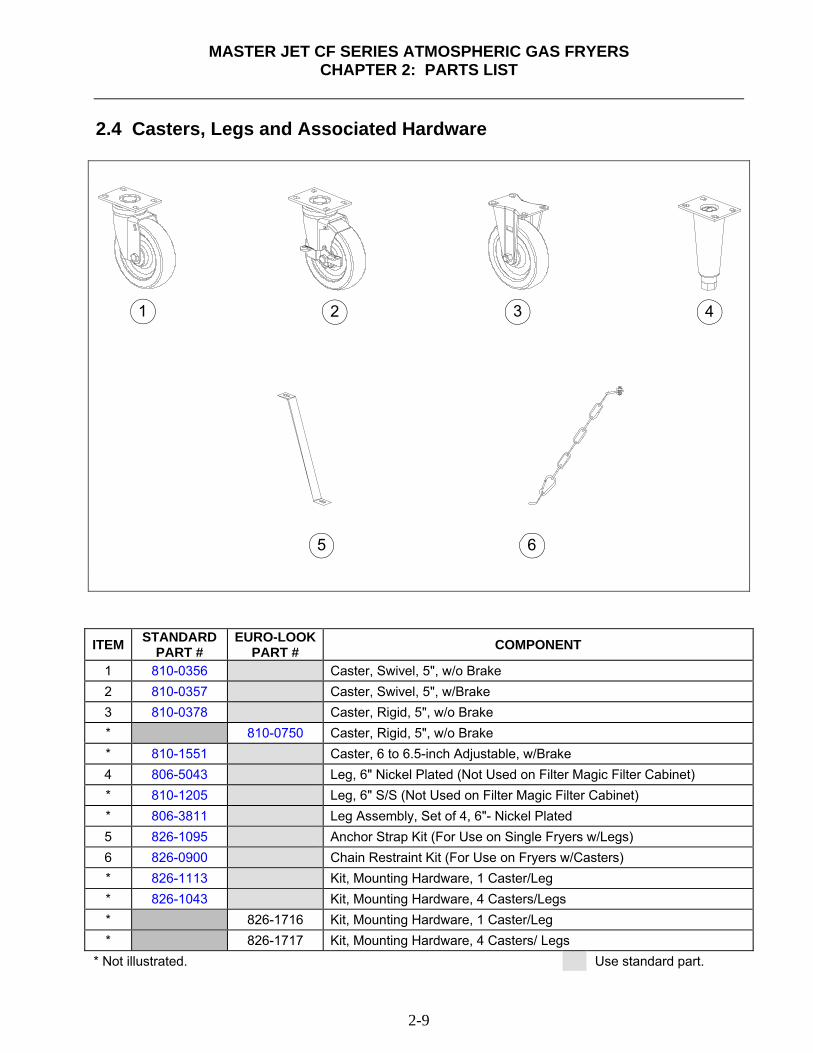
MASTER JET CF SERIES ATMOSPHERIC GAS FRYERS
CHAPTER 2: PARTS LIST
2-9
2.4 Casters, Legs and Associated Hardware
1 2 3 4
5 6
ITEM STANDARD
PART # EURO-LOOK
PART # COMPONENT
1 810-0356 Caster, Swivel, 5", w/o Brake 2 810-0357 Caster, Swivel, 5", w/Brake 3 810-0378 Caster, Rigid, 5", w/o Brake * 810-0750 Caster, Rigid, 5", w/o Brake * 810-1551 Caster, 6 to 6.5-inch Adjustable, w/Brake 4 806-5043 Leg, 6" Nickel Plated (Not Used on Filter Magic Filter Cabinet) * 810-1205 Leg, 6" S/S (Not Used on Filter Magic Filter Cabinet) * 806-3811 Leg Assembly, Set of 4, 6"- Nickel Plated 5 826-1095 Anchor Strap Kit (For Use on Single Fryers w/Legs) 6 826-0900 Chain Restraint Kit (For Use on Fryers w/Casters) * 826-1113 Kit, Mounting Hardware, 1 Caster/Leg * 826-1043 Kit, Mounting Hardware, 4 Casters/Legs * 826-1716 Kit, Mounting Hardware, 1 Caster/Leg * 826-1717 Kit, Mounting Hardware, 4 Casters/ Legs
* Not illustrated. Use standard part.
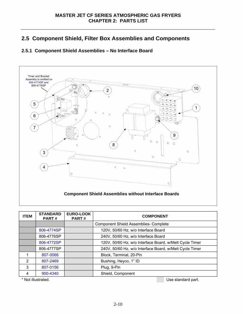
MASTER JET CF SERIES ATMOSPHERIC GAS FRYERS
CHAPTER 2: PARTS LIST
2-10
2.5 Component Shield, Filter Box Assemblies and Components 2.5.1 Component Shield Assemblies – No Interface Board
Component Shield Assemblies without Interface Boards
Timer and Bracket Assembly is omitted on
806-4774SP and806-4776SP
1
2
3
4
5
6
7
8
9
10
ITEM STANDARD
PART # EURO-LOOK
PART # COMPONENT
Component Shield Assemblies- Complete 806-4774SP 120V, 50/60 Hz, w/o Interface Board 806-4776SP 240V, 50/60 Hz, w/o Interface Board 806-4772SP 120V, 50/60 Hz, w/o Interface Board, w/Melt Cycle Timer 806-4777SP 240V, 50/60 Hz, w/o Interface Board, w/Melt Cycle Timer 1 807-0066 Block, Terminal, 20-Pin 2 807-2469 Bushing, Heyco, 1” ID 3 807-0156 Plug, 9-Pin 4 900-4340 Shield, Component
* Not illustrated. Use standard part.
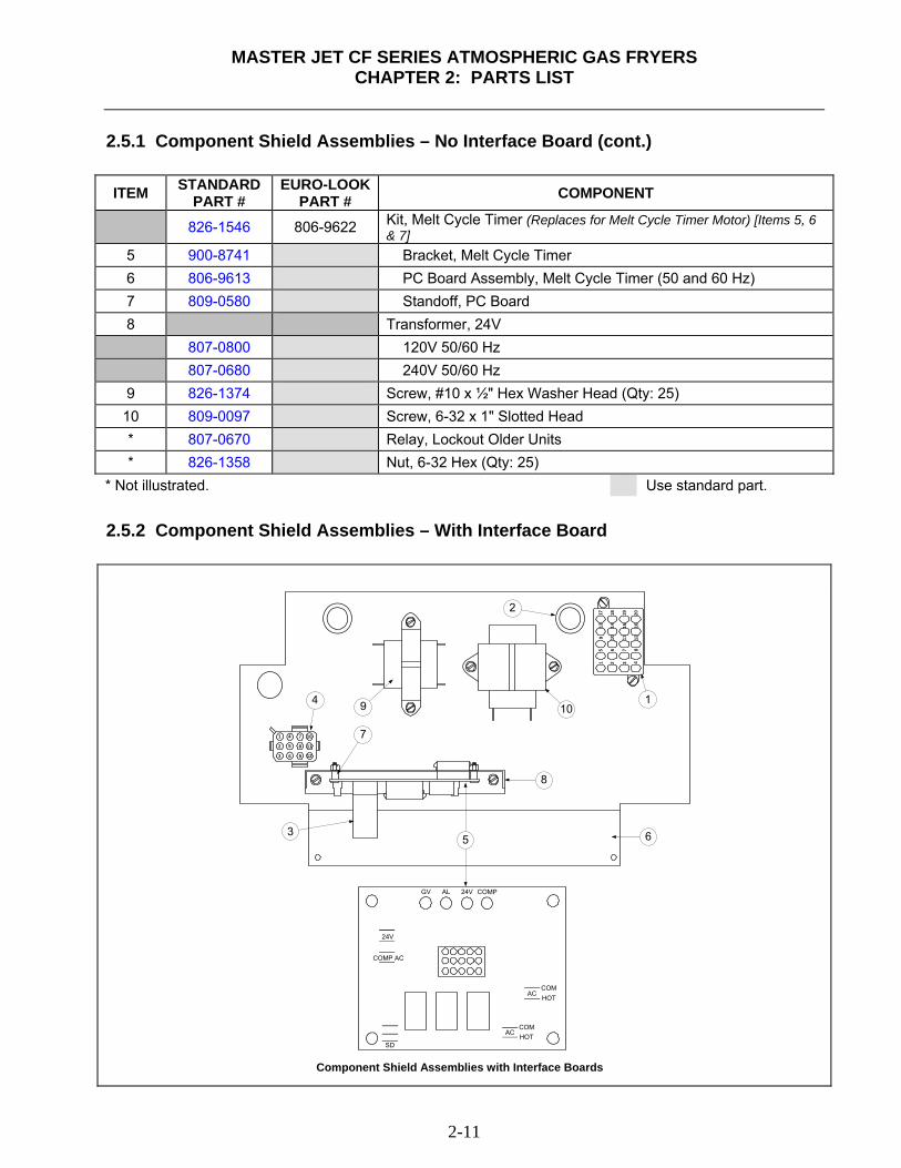
MASTER JET CF SERIES ATMOSPHERIC GAS FRYERS
CHAPTER 2: PARTS LIST
2-11
2.5.1 Component Shield Assemblies – No Interface Board (cont.) ITEM STANDARD
PART # EURO-LOOK
PART # COMPONENT
826-1546 806-9622 Kit, Melt Cycle Timer (Replaces for Melt Cycle Timer Motor) [Items 5, 6 & 7]
5 900-8741 Bracket, Melt Cycle Timer 6 806-9613 PC Board Assembly, Melt Cycle Timer (50 and 60 Hz) 7 809-0580 Standoff, PC Board 8 Transformer, 24V 807-0800 120V 50/60 Hz 807-0680 240V 50/60 Hz 9 826-1374 Screw, #10 x ½" Hex Washer Head (Qty: 25) 10 809-0097 Screw, 6-32 x 1" Slotted Head * 807-0670 Relay, Lockout Older Units * 826-1358 Nut, 6-32 Hex (Qty: 25)
* Not illustrated. Use standard part.
2.5.2 Component Shield Assemblies – With Interface Board
24V
COMP AC
GV AL 24V COMP
SD
ACCOMHOT
ACCOMHOT
Component Shield Assemblies with Interface Boards
1
2
3
4
5
6
7
8
9
10
11
12
1 2 3 4
5 6 7 8
9 10 11 12
13 14 15 16
17 18 19 20
2
1
3
4
5 6
7
8
9 10
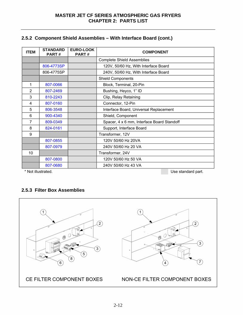
MASTER JET CF SERIES ATMOSPHERIC GAS FRYERS
CHAPTER 2: PARTS LIST
2-12
2.5.2 Component Shield Assemblies – With Interface Board (cont.)
ITEM STANDARD PART #
EURO-LOOK PART # COMPONENT
Complete Shield Assemblies 806-4773SP 120V, 50/60 Hz, With Interface Board 806-4775SP 240V, 50/60 Hz, With Interface Board Shield Components 1 807-0066 Block, Terminal, 20-Pin 2 807-2469 Bushing, Heyco, 1” ID 3 810-2243 Clip, Relay Retaining 4 807-0160 Connector, 12-Pin 5 806-3548 Interface Board, Universal Replacement 6 900-4340 Shield, Component 7 809-0349 Spacer, 4 x 6 mm, Interface Board Standoff 8 824-0161 Support, Interface Board 9 Transformer, 12V 807-0855 120V 50/60 Hz 20VA 807-0979 240V 50/60 Hz 20 VA
10 Transformer, 24V 807-0800 120V 50/60 Hz 50 VA 807-0680 240V 50/60 Hz 43 VA
* Not illustrated. Use standard part.
2.5.3 Filter Box Assemblies
1
2
35
68
CE FILTER COMPONENT BOXES NON-CE FILTER COMPONENT BOXES
1
2
3
4 7
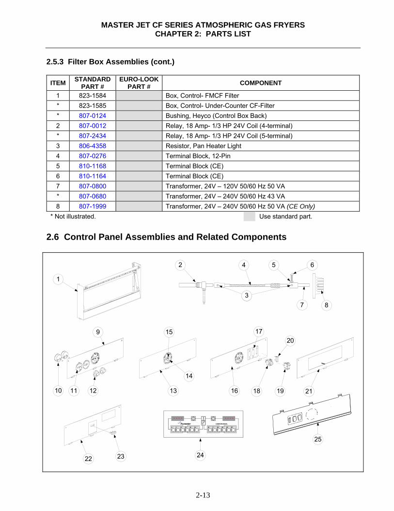
MASTER JET CF SERIES ATMOSPHERIC GAS FRYERS
CHAPTER 2: PARTS LIST
2-13
2.5.3 Filter Box Assemblies (cont.)
ITEM STANDARD PART #
EURO-LOOKPART # COMPONENT
1 823-1584 Box, Control- FMCF Filter * 823-1585 Box, Control- Under-Counter CF-Filter * 807-0124 Bushing, Heyco (Control Box Back) 2 807-0012 Relay, 18 Amp- 1/3 HP 24V Coil (4-terminal) * 807-2434 Relay, 18 Amp- 1/3 HP 24V Coil (5-terminal) 3 806-4358 Resistor, Pan Heater Light 4 807-0276 Terminal Block, 12-Pin 5 810-1168 Terminal Block (CE) 6 810-1164 Terminal Block (CE) 7 807-0800 Transformer, 24V – 120V 50/60 Hz 50 VA * 807-0680 Transformer, 24V – 240V 50/60 Hz 43 VA 8 807-1999 Transformer, 24V – 240V 50/60 Hz 50 VA (CE Only)
* Not illustrated. Use standard part.
2.6 Control Panel Assemblies and Related Components
1
9
10 11 13 16
17
18 19
20
2112
14
15
2422 23
2
3
5 6
7 8
4
25
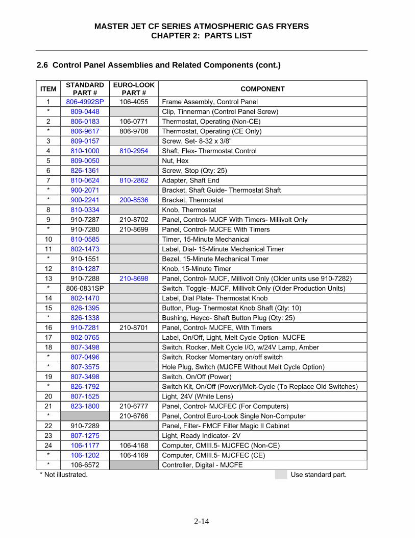
MASTER JET CF SERIES ATMOSPHERIC GAS FRYERS
CHAPTER 2: PARTS LIST
2-14
2.6 Control Panel Assemblies and Related Components (cont.) ITEM STANDARD
PART # EURO-LOOK
PART # COMPONENT
1 806-4992SP 106-4055 Frame Assembly, Control Panel * 809-0448 Clip, Tinnerman (Control Panel Screw) 2 806-0183 106-0771 Thermostat, Operating (Non-CE) * 806-9617 806-9708 Thermostat, Operating (CE Only) 3 809-0157 Screw, Set- 8-32 x 3/8" 4 810-1000 810-2954 Shaft, Flex- Thermostat Control 5 809-0050 Nut, Hex 6 826-1361 Screw, Stop (Qty: 25) 7 810-0624 810-2862 Adapter, Shaft End * 900-2071 Bracket, Shaft Guide- Thermostat Shaft * 900-2241 200-8536 Bracket, Thermostat 8 810-0334 Knob, Thermostat 9 910-7287 210-8702 Panel, Control- MJCF With Timers- Millivolt Only * 910-7280 210-8699 Panel, Control- MJCFE With Timers
10 810-0585 Timer, 15-Minute Mechanical 11 802-1473 Label, Dial- 15-Minute Mechanical Timer * 910-1551 Bezel, 15-Minute Mechanical Timer
12 810-1287 Knob, 15-Minute Timer 13 910-7288 210-8698 Panel, Control- MJCF, Millivolt Only (Older units use 910-7282) * 806-0831SP Switch, Toggle- MJCF, Millivolt Only (Older Production Units)
14 802-1470 Label, Dial Plate- Thermostat Knob 15 826-1395 Button, Plug- Thermostat Knob Shaft (Qty: 10) * 826-1338 Bushing, Heyco- Shaft Button Plug (Qty: 25)
16 910-7281 210-8701 Panel, Control- MJCFE, With Timers 17 802-0765 Label, On/Off, Light, Melt Cycle Option- MJCFE 18 807-3498 Switch, Rocker, Melt Cycle I/O, w/24V Lamp, Amber * 807-0496 Switch, Rocker Momentary on/off switch * 807-3575 Hole Plug, Switch (MJCFE Without Melt Cycle Option)
19 807-3498 Switch, On/Off (Power) * 826-1792 Switch Kit, On/Off (Power)/Melt-Cycle (To Replace Old Switches)
20 807-1525 Light, 24V (White Lens) 21 823-1800 210-6777 Panel, Control- MJCFEC (For Computers) * 210-6766 Panel, Control Euro-Look Single Non-Computer
22 910-7289 Panel, Filter- FMCF Filter Magic II Cabinet 23 807-1275 Light, Ready Indicator- 2V 24 106-1177 106-4168 Computer, CMIII.5- MJCFEC (Non-CE) * 106-1202 106-4169 Computer, CMIII.5- MJCFEC (CE) * 106-6572 Controller, Digital - MJCFE
* Not illustrated. Use standard part.
MASTER JET CF SERIES ATMOSPHERIC GAS FRYERS
CHAPTER 2: PARTS LIST
2-15
2.6 Control Panel Assemblies and Related Components (cont.)
ITEM STANDARD PART #
EURO-LOOKPART # COMPONENT
* 806-2071 Harness, Computer (Computer To Interface Board) 25 210-8702 Panel, Control w/ Timers CF Euro-Look * 106-3373 Controller Assembly, Basket Lift w/ Timers * 806-3660 Sound Device, High Output * 806-4797 Buzzer Assembly * 910-7315 Panel, Spreader Control CF Blank Panel Euro-Look
* Not illustrated. Use standard part.
2.7 Filtration System Components 2.7.1.1 Filter Magic II Drain Manifold Components
Clamp Detail
11
1213
1415
16
17
1819
20
To DrainValve
21
1
2
3
4
10
56
78
9

MASTER JET CF SERIES ATMOSPHERIC GAS FRYERS
CHAPTER 2: PARTS LIST
2-16
2.7.1.1 Filter Magic Drain Manifold Components (cont.) ITEM STANDARD
PART # ** COMPONENT
1 900-0757 Cover, Drain End, Square Drain- FMCF 2 816-0032 Gasket, Flange, Square Drain- FMCF 3 823-0717 Tube, Square Drain- 2-½ x 15.38"- FMCF * 826-0715SP Drain Tube Kit (Gaskets, Clamps, Connecting Hardware, Clean-Out Cover) 4 823-0719 Elbow, Square Drain- FMCF * 826-0716SP Sq Drain Elbow Kit (Elbow, Gaskets, Clamps, Connecting Hardware) 806-4068SP Elbow, Swivel, Complete Assembly (Items 5-9)- FMCF 5 823-1091 Tube Assembly 6 816-0083 O-Ring, Swivel Collar 7 809-0115 Screw, Retainer- 10-32 x ¼" Slotted Head 8 823-1092 Collar, Swivel Drain 9 810-0388 Knob, Clamping- Swivel Drain Collar 10 823-0714 Tube, Square Drain- 2-½ x 5.22"- FMCF Spreader Cabinet Option 11 816-0021 Gasket, Drain Cleanout – FMCF 12 826-1348 Cover, Drain Cleanout – FMCF (Qty: 5) 13 826-1382 Nut, Wing- 8-32 (Qty: 10) 14 823-0718 Tube, Square Drain- 2-½ x 8" – FMCF 15 810-0396 Clamp, Square Drain Flange – FMCF * 826-0877 Clamp Kit – FMCF
16 826-1376 Nut, Keps- 10-32 (Drain Flange Clamp – Qty: 10) 17 826-1369 Screw, 10-32 x ½" Hex Head (Qty: 10) 18 809-0347 Nut, Drain Retainer (Conduit Nut) 19 826-1345 Washer Retainer, Drain Retainer Nut (Qty: 25) 20 816-0092 Grommet, Drain Retainer- 1" 21 813-0284 Nipple, Straight With Taper- 1 x ¾" NPT BM
* Not illustrated. ** See page 2-17 for a Euro-Look parts list.
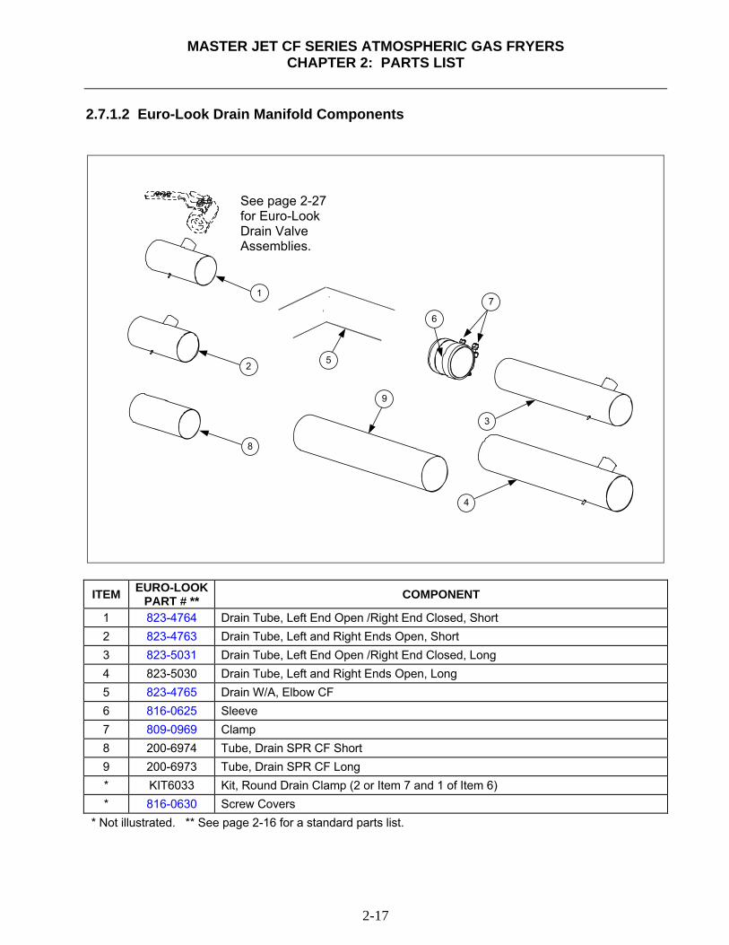
MASTER JET CF SERIES ATMOSPHERIC GAS FRYERS
CHAPTER 2: PARTS LIST
2-17
2.7.1.2 Euro-Look Drain Manifold Components
7
6
3
4
52
1
8
9
ITEM EURO-LOOK
PART # ** COMPONENT
1 823-4764 Drain Tube, Left End Open /Right End Closed, Short 2 823-4763 Drain Tube, Left and Right Ends Open, Short 3 823-5031 Drain Tube, Left End Open /Right End Closed, Long 4 823-5030 Drain Tube, Left and Right Ends Open, Long 5 823-4765 Drain W/A, Elbow CF 6 816-0625 Sleeve 7 809-0969 Clamp 8 200-6974 Tube, Drain SPR CF Short 9 200-6973 Tube, Drain SPR CF Long * KIT6033 Kit, Round Drain Clamp (2 or Item 7 and 1 of Item 6) * 816-0630 Screw Covers
* Not illustrated. ** See page 2-16 for a standard parts list.
See page 2-27 for Euro-Look Drain Valve Assemblies.
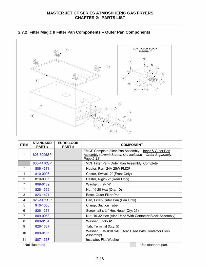
MASTER JET CF SERIES ATMOSPHERIC GAS FRYERS
CHAPTER 2: PARTS LIST
2-18
2.7.2 Filter Magic II Filter Pan Components – Outer Pan Components
1
2
3
4
5
6
78
97
10
11
12
13
14
158
7
10
16
17
18
1920
21 22
23
CONTACTOR BLOCKASSEMBLY
ITEM STANDARD PART #
EURO-LOOK PART # COMPONENT
* 806-6095SP FMCF Complete Filter Pan Assembly – Inner & Outer Pan
Assembly (Crumb Screen Not Included – Order Separately, Page 2-18)
806-4470SP FMCF Filter Pan- Outer Pan Assembly, Complete * 806-4373 Heater, Pan- 24V 25W FMCF 1 810-0006 Caster, Swivel- 2" (Front Only) 2 810-0005 Caster, Rigid- 2" (Rear Only) * 809-0189 Washer, Flat- ¼" * 826-1362 Nut, ¼-20 Hex (Qty: 10) 3 823-1421 Base, Outer Filter Pan 4 823-1452SP Pan, Filter- Outer Pan (Pan Only) 5 910-1350 Clamp, Suction Tube 6 826-1371 Screw, #8 x ½" Hex Head (Qty: 25) 7 809-0053 Nut, 10-32 Hex (Also Used With Contactor Block Assembly) 8 809-0184 Washer, Lock- #10 9 826-1337 Tab, Terminal (Qty: 5)
10 809-0185 Washer, Flat- #10 SAE (Also Used With Contactor Block Assembly)
11 807-1367 Insulator, Flat Washer * Not illustrated. Use standard part.
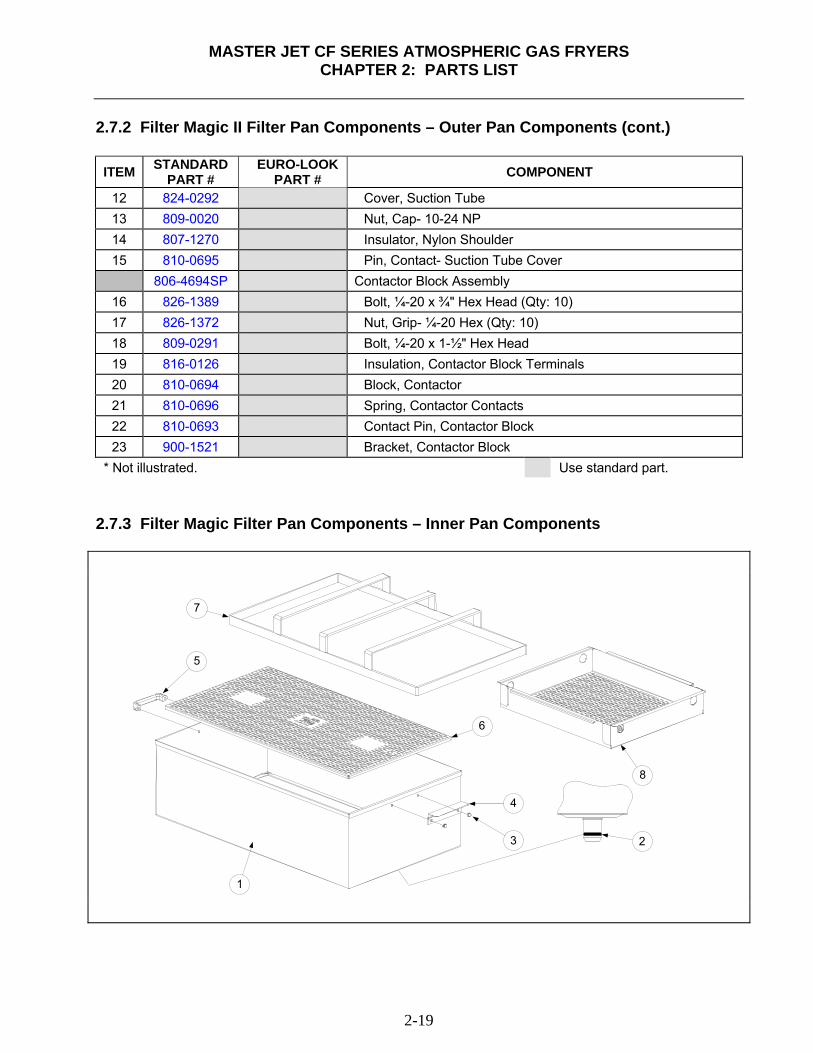
MASTER JET CF SERIES ATMOSPHERIC GAS FRYERS
CHAPTER 2: PARTS LIST
2-19
2.7.2 Filter Magic II Filter Pan Components – Outer Pan Components (cont.)
ITEM STANDARD PART #
EURO-LOOK PART # COMPONENT
12 824-0292 Cover, Suction Tube 13 809-0020 Nut, Cap- 10-24 NP 14 807-1270 Insulator, Nylon Shoulder 15 810-0695 Pin, Contact- Suction Tube Cover 806-4694SP Contactor Block Assembly
16 826-1389 Bolt, ¼-20 x ¾" Hex Head (Qty: 10) 17 826-1372 Nut, Grip- ¼-20 Hex (Qty: 10) 18 809-0291 Bolt, ¼-20 x 1-½" Hex Head 19 816-0126 Insulation, Contactor Block Terminals 20 810-0694 Block, Contactor 21 810-0696 Spring, Contactor Contacts 22 810-0693 Contact Pin, Contactor Block 23 900-1521 Bracket, Contactor Block
* Not illustrated. Use standard part. 2.7.3 Filter Magic Filter Pan Components – Inner Pan Components
1
23
4
5
6
7
8
MASTER JET CF SERIES ATMOSPHERIC GAS FRYERS
CHAPTER 2: PARTS LIST
2-20
2.7.3 Filter Magic Filter Pan Components – Inner Pan Components (cont.) ITEM STANDARD
PART # EURO-LOOK
PART # COMPONENT
* 806-6095SP FMCF Complete Filter Pan Assembly – Inner & Outer Pan Assembly (Crumb Screen Not Included – Order Item #8 Below)
1 823-1745SP Pan, Inner- FMCF * 806-4866SP Pan Assembly, Inner- FMCF (Crumb Screen Not Included) 2 816-0117 O-ring, Inner Pan Connection 3 809-0045 Nut, Cap- 10-32 4 910-1366 Handle, Filter Pan, Back (Nearest End With Hole In Pan Bottom) 5 810-0180 Handle, Filter Pan, Front (Nearest Door On Filter Cabinet) 6 823-2010 Screen, Filter Paper Support 7 810-1409 Ring, Hold-Down- FMCF * 803-0171 Paper, Filter (100 Sheets) 33-¼ x 21" * 803-0002 Powder, Filter (100 1-Cup Applications) 8 824-0417 Screen Assembly, Crumb- FMCF
* Not illustrated. Use standard part.
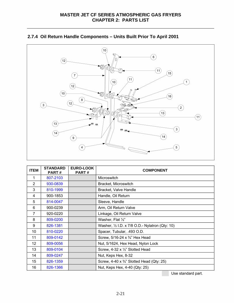
MASTER JET CF SERIES ATMOSPHERIC GAS FRYERS
CHAPTER 2: PARTS LIST
2-21
2.7.4 Oil Return Handle Components – Units Built Prior To April 2001
1
2
3
3
4 5
6
7
8
9
11
11
12
13
14
15
1610
12
12
13
14
1110
10
ITEM STANDARD
PART # EURO-LOOK
PART # COMPONENT
1 807-2103 Microswitch 2 930-0839 Bracket, Microswitch 3 810-1999 Bracket, Valve Handle 4 900-1853 Handle, Oil Return 5 814-0047 Sleeve, Handle 6 900-0239 Arm, Oil Return Valve 7 920-0220 Linkage, Oil Return Valve 8 809-0200 Washer, Flat ½” 9 826-1381 Washer, ½ I.D. x 7/8 O.D.- Nylatron (Qty: 10) 10 810-0220 Spacer, Tubular, .493 O.D. 11 809-0142 Screw, 5/16-24 x ¾” Hex Head 12 809-0056 Nut, 5/1624, Hex Head, Nylon Lock 13 809-0104 Screw, 4-32 x ½” Slotted Head 14 809-0247 Nut, Keps Hex, 8-32 15 826-1359 Screw, 4-40 x ¾” Slotted Head (Qty: 25) 16 826-1366 Nut, Keps Hex, 4-40 (Qty: 25)
Use standard part.
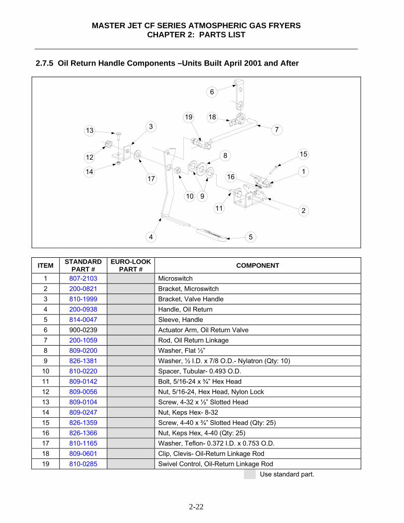
MASTER JET CF SERIES ATMOSPHERIC GAS FRYERS
CHAPTER 2: PARTS LIST
2-22
2.7.5 Oil Return Handle Components –Units Built April 2001 and After
1
2
3
4 5
6
7
8
910
11
12
13
14
15
1617
1819
ITEM STANDARD
PART # EURO-LOOK
PART # COMPONENT
1 807-2103 Microswitch 2 200-0821 Bracket, Microswitch 3 810-1999 Bracket, Valve Handle 4 200-0938 Handle, Oil Return 5 814-0047 Sleeve, Handle 6 900-0239 Actuator Arm, Oil Return Valve 7 200-1059 Rod, Oil Return Linkage 8 809-0200 Washer, Flat ½” 9 826-1381 Washer, ½ I.D. x 7/8 O.D.- Nylatron (Qty: 10) 10 810-0220 Spacer, Tubular- 0.493 O.D. 11 809-0142 Bolt, 5/16-24 x ¾” Hex Head 12 809-0056 Nut, 5/16-24, Hex Head, Nylon Lock 13 809-0104 Screw, 4-32 x ½” Slotted Head 14 809-0247 Nut, Keps Hex- 8-32 15 826-1359 Screw, 4-40 x ¾” Slotted Head (Qty: 25) 16 826-1366 Nut, Keps Hex, 4-40 (Qty: 25) 17 810-1165 Washer, Teflon- 0.372 I.D. x 0.753 O.D. 18 809-0601 Clip, Clevis- Oil-Return Linkage Rod 19 810-0285 Swivel Control, Oil-Return Linkage Rod
Use standard part.
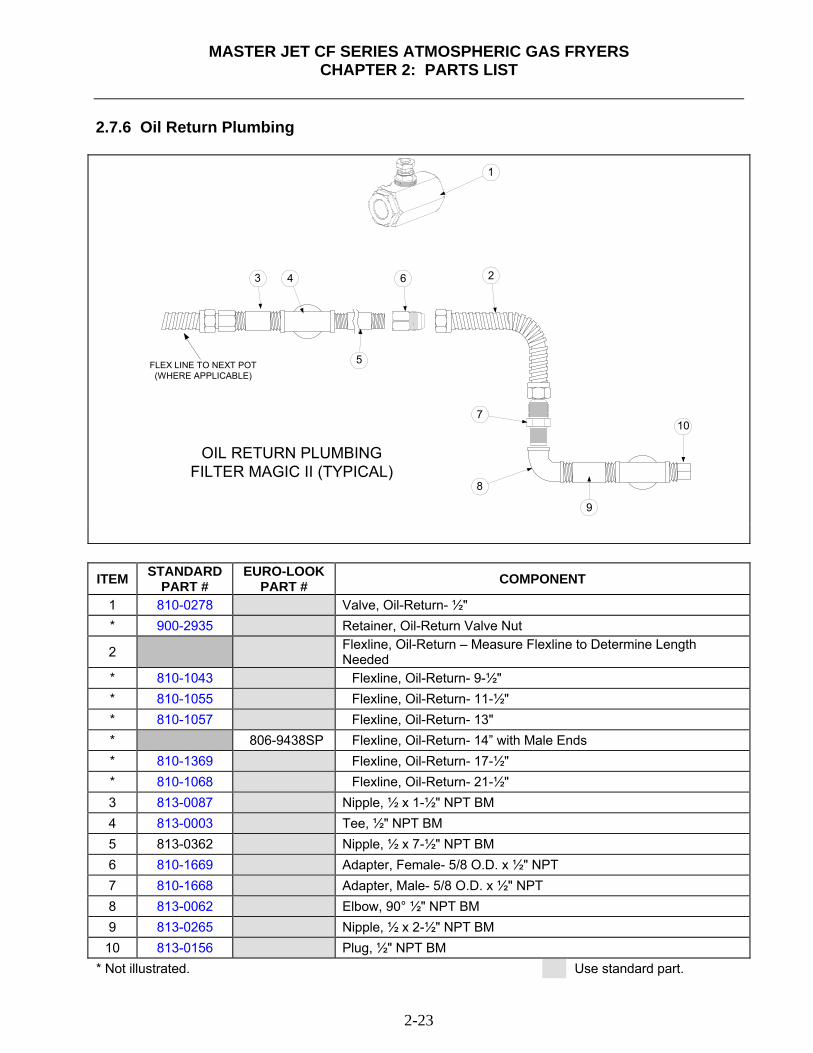
MASTER JET CF SERIES ATMOSPHERIC GAS FRYERS
CHAPTER 2: PARTS LIST
2-23
2.7.6 Oil Return Plumbing
FLEX LINE TO NEXT POT(WHERE APPLICABLE)
OIL RETURN PLUMBINGFILTER MAGIC II (TYPICAL)
1
23 4
5
7
8
9
10
6
ITEM STANDARD
PART # EURO-LOOK
PART # COMPONENT
1 810-0278 Valve, Oil-Return- ½" * 900-2935 Retainer, Oil-Return Valve Nut
2 Flexline, Oil-Return – Measure Flexline to Determine Length Needed
* 810-1043 Flexline, Oil-Return- 9-½" * 810-1055 Flexline, Oil-Return- 11-½" * 810-1057 Flexline, Oil-Return- 13" * 806-9438SP Flexline, Oil-Return- 14” with Male Ends * 810-1369 Flexline, Oil-Return- 17-½" * 810-1068 Flexline, Oil-Return- 21-½" 3 813-0087 Nipple, ½ x 1-½" NPT BM 4 813-0003 Tee, ½" NPT BM 5 813-0362 Nipple, ½ x 7-½" NPT BM 6 810-1669 Adapter, Female- 5/8 O.D. x ½" NPT 7 810-1668 Adapter, Male- 5/8 O.D. x ½" NPT 8 813-0062 Elbow, 90° ½" NPT BM 9 813-0265 Nipple, ½ x 2-½" NPT BM 10 813-0156 Plug, ½" NPT BM
* Not illustrated. Use standard part.
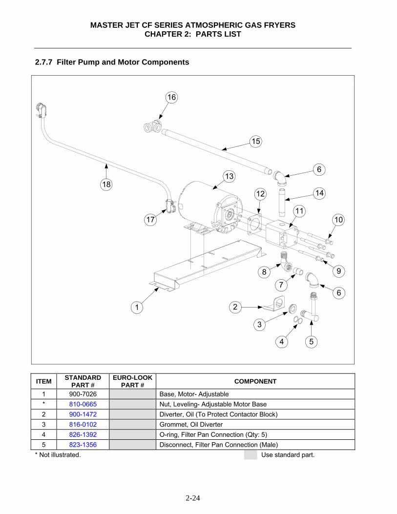
MASTER JET CF SERIES ATMOSPHERIC GAS FRYERS
CHAPTER 2: PARTS LIST
2-24
2.7.7 Filter Pump and Motor Components
1 2
3
4 5
67
8 9
11
14
13
15
12
6
16
17
18
10
ITEM STANDARD
PART # EURO-LOOK
PART # COMPONENT
1 900-7026 Base, Motor- Adjustable * 810-0665 Nut, Leveling- Adjustable Motor Base 2 900-1472 Diverter, Oil (To Protect Contactor Block) 3 816-0102 Grommet, Oil Diverter 4 826-1392 O-ring, Filter Pan Connection (Qty: 5) 5 823-1356 Disconnect, Filter Pan Connection (Male)
* Not illustrated. Use standard part.
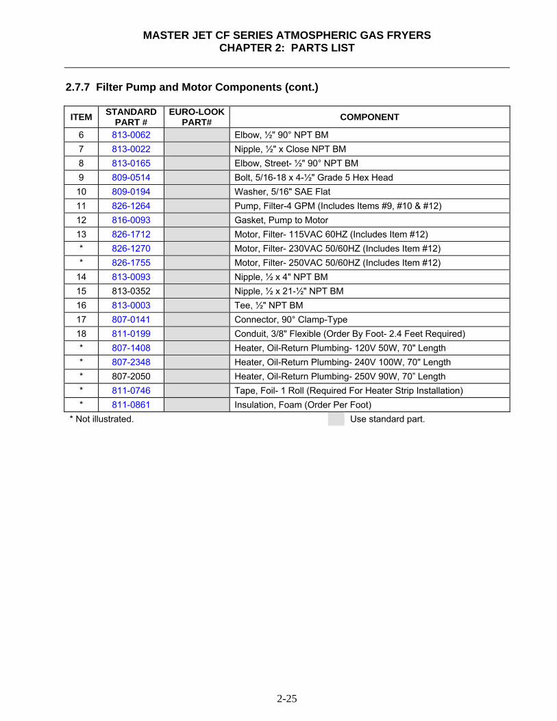
MASTER JET CF SERIES ATMOSPHERIC GAS FRYERS
CHAPTER 2: PARTS LIST
2-25
2.7.7 Filter Pump and Motor Components (cont.) ITEM STANDARD
PART # EURO-LOOK
PART# COMPONENT
6 813-0062 Elbow, ½" 90° NPT BM 7 813-0022 Nipple, ½" x Close NPT BM 8 813-0165 Elbow, Street- ½" 90° NPT BM 9 809-0514 Bolt, 5/16-18 x 4-½" Grade 5 Hex Head 10 809-0194 Washer, 5/16" SAE Flat 11 826-1264 Pump, Filter-4 GPM (Includes Items #9, #10 & #12) 12 816-0093 Gasket, Pump to Motor 13 826-1712 Motor, Filter- 115VAC 60HZ (Includes Item #12) * 826-1270 Motor, Filter- 230VAC 50/60HZ (Includes Item #12) * 826-1755 Motor, Filter- 250VAC 50/60HZ (Includes Item #12)
14 813-0093 Nipple, ½ x 4" NPT BM 15 813-0352 Nipple, ½ x 21-½" NPT BM 16 813-0003 Tee, ½" NPT BM 17 807-0141 Connector, 90° Clamp-Type 18 811-0199 Conduit, 3/8" Flexible (Order By Foot- 2.4 Feet Required) * 807-1408 Heater, Oil-Return Plumbing- 120V 50W, 70" Length * 807-2348 Heater, Oil-Return Plumbing- 240V 100W, 70" Length * 807-2050 Heater, Oil-Return Plumbing- 250V 90W, 70” Length * 811-0746 Tape, Foil- 1 Roll (Required For Heater Strip Installation) * 811-0861 Insulation, Foam (Order Per Foot)
* Not illustrated. Use standard part.
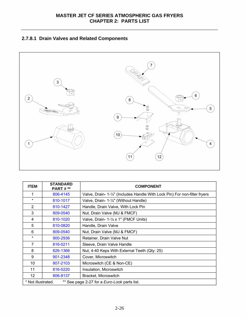
MASTER JET CF SERIES ATMOSPHERIC GAS FRYERS
CHAPTER 2: PARTS LIST
2-26
2.7.8.1 Drain Valves and Related Components
1
2
3
4
5
6
7
8
9
10
11 12
ITEM STANDARD PART # ** COMPONENT
1 806-4145 Valve, Drain- 1-¼" (Includes Handle With Lock Pin) For non-filter fryers * 810-1017 Valve, Drain- 1-¼" (Without Handle) 2 810-1427 Handle, Drain Valve, With Lock Pin 3 809-0540 Nut, Drain Valve (MJ & FMCF) 4 810-1020 Valve, Drain- 1-¼ x 1" (FMCF Units) 5 810-0820 Handle, Drain Valve 6 809-0540 Nut, Drain Valve (MJ & FMCF) * 900-2936 Retainer, Drain Valve Nut 7 816-0211 Sleeve, Drain Valve Handle 8 826-1366 Nut, 4-40 Keps With External Teeth (Qty: 25) 9 901-2348 Cover, Microswitch 10 807-2103 Microswitch (CE & Non-CE) 11 816-0220 Insulation, Microswitch 12 806-8137 Bracket, Microswitch
* Not illustrated. ** See page 2-27 for a Euro-Look parts list.
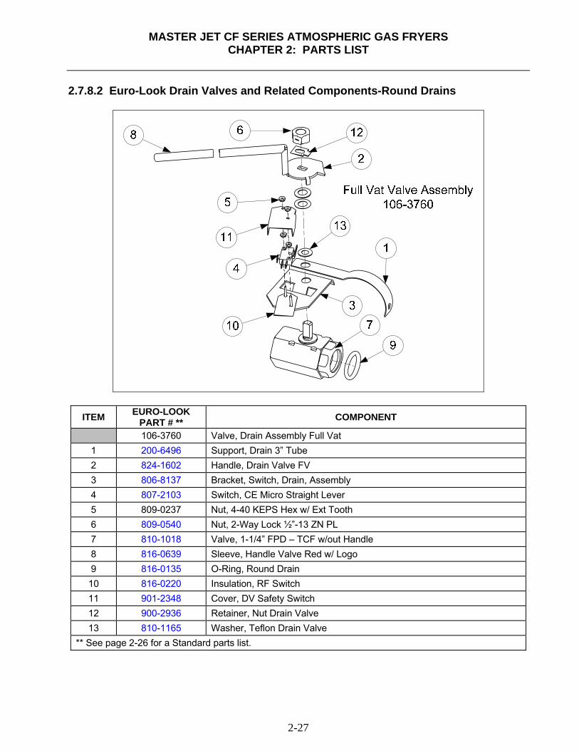
MASTER JET CF SERIES ATMOSPHERIC GAS FRYERS
CHAPTER 2: PARTS LIST
2-27
2.7.8.2 Euro-Look Drain Valves and Related Components-Round Drains
ITEM EURO-LOOK PART # ** COMPONENT
106-3760 Valve, Drain Assembly Full Vat 1 200-6496 Support, Drain 3” Tube 2 824-1602 Handle, Drain Valve FV 3 806-8137 Bracket, Switch, Drain, Assembly 4 807-2103 Switch, CE Micro Straight Lever 5 809-0237 Nut, 4-40 KEPS Hex w/ Ext Tooth 6 809-0540 Nut, 2-Way Lock ½”-13 ZN PL 7 810-1018 Valve, 1-1/4” FPD – TCF w/out Handle 8 816-0639 Sleeve, Handle Valve Red w/ Logo 9 816-0135 O-Ring, Round Drain 10 816-0220 Insulation, RF Switch 11 901-2348 Cover, DV Safety Switch 12 900-2936 Retainer, Nut Drain Valve 13 810-1165 Washer, Teflon Drain Valve
** See page 2-26 for a Standard parts list.
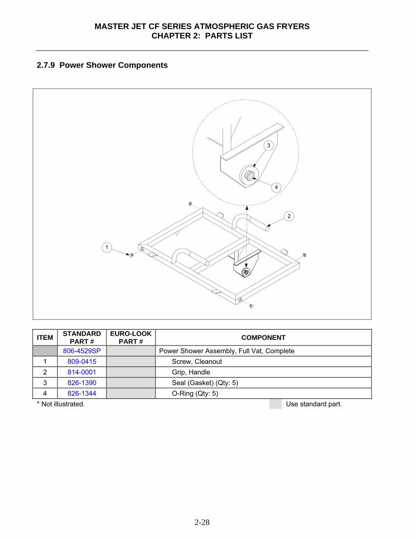
MASTER JET CF SERIES ATMOSPHERIC GAS FRYERS
CHAPTER 2: PARTS LIST
2-28
2.7.9 Power Shower Components
1
2
3
4
ITEM STANDARD
PART # EURO-LOOK
PART # COMPONENT
806-4529SP Power Shower Assembly, Full Vat, Complete 1 809-0415 Screw, Cleanout 2 814-0001 Grip, Handle 3 826-1390 Seal (Gasket) (Qty: 5) 4 826-1344 O-Ring (Qty: 5)
* Not illustrated. Use standard part.
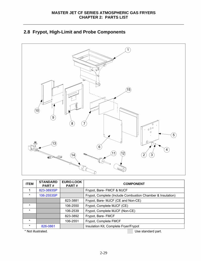
MASTER JET CF SERIES ATMOSPHERIC GAS FRYERS
CHAPTER 2: PARTS LIST
2-29
2.8 Frypot, High-Limit and Probe Components
1
2 3
4
5
6
78
9
10
11
13
14 12
15
ITEM STANDARD PART #
EURO-LOOKPART # COMPONENT
1 823-3893SP Frypot, Bare- FMCF & MJCF * 106-2553SP Frypot, Complete (Include Combustion Chamber & Insulation) 823-3881 Frypot, Bare- MJCF (CE and Non-CE) * 106-2550 Frypot, Complete MJCF (CE) * 106-2539 Frypot, Complete MJCF (Non-CE) 823-3892 Frypot, Bare- FMCF * 106-2551 Frypot, Complete FMCF * 826-0861 Insulation Kit, Complete Fryer/Frypot
* Not illustrated. Use standard part.
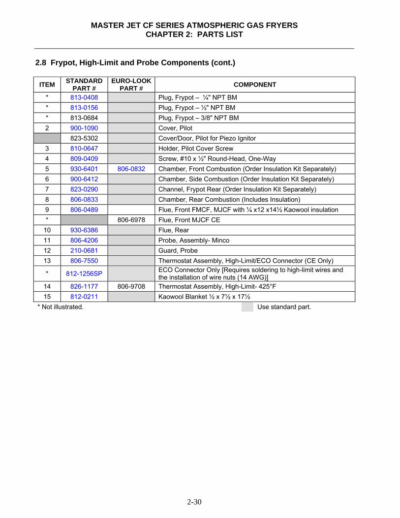
MASTER JET CF SERIES ATMOSPHERIC GAS FRYERS
CHAPTER 2: PARTS LIST
2-30
2.8 Frypot, High-Limit and Probe Components (cont.)
ITEM STANDARD PART #
EURO-LOOK PART # COMPONENT
* 813-0408 Plug, Frypot – ¼" NPT BM * 813-0156 Plug, Frypot – ½" NPT BM * 813-0684 Plug, Frypot – 3/8" NPT BM 2 900-1090 Cover, Pilot 823-5302 Cover/Door, Pilot for Piezo Ignitor
3 810-0647 Holder, Pilot Cover Screw 4 809-0409 Screw, #10 x ½" Round-Head, One-Way 5 930-6401 806-0832 Chamber, Front Combustion (Order Insulation Kit Separately) 6 900-6412 Chamber, Side Combustion (Order Insulation Kit Separately) 7 823-0290 Channel, Frypot Rear (Order Insulation Kit Separately) 8 806-0833 Chamber, Rear Combustion (Includes Insulation) 9 806-0489 Flue, Front FMCF, MJCF with ¼ x12 x14½ Kaowool insulation * 806-6978 Flue, Front MJCF CE
10 930-6386 Flue, Rear 11 806-4206 Probe, Assembly- Minco 12 210-0681 Guard, Probe 13 806-7550 Thermostat Assembly, High-Limit/ECO Connector (CE Only)
* 812-1256SP ECO Connector Only [Requires soldering to high-limit wires and the installation of wire nuts (14 AWG)]
14 826-1177 806-9708 Thermostat Assembly, High-Limit- 425°F 15 812-0211 Kaowool Blanket ½ x 7½ x 17½
* Not illustrated. Use standard part.
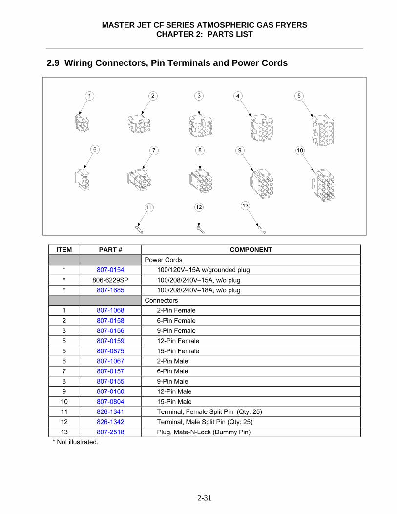
MASTER JET CF SERIES ATMOSPHERIC GAS FRYERS
CHAPTER 2: PARTS LIST
2-31
2.9 Wiring Connectors, Pin Terminals and Power Cords
1 2 4 53
6 7 9 108
11 1312
ITEM PART # COMPONENT Power Cords * 807-0154 100/120V–15A w/grounded plug * 806-6229SP 100/208/240V–15A, w/o plug * 807-1685 100/208/240V–18A, w/o plug Connectors 1 807-1068 2-Pin Female 2 807-0158 6-Pin Female 3 807-0156 9-Pin Female 5 807-0159 12-Pin Female 5 807-0875 15-Pin Female 6 807-1067 2-Pin Male 7 807-0157 6-Pin Male 8 807-0155 9-Pin Male 9 807-0160 12-Pin Male 10 807-0804 15-Pin Male 11 826-1341 Terminal, Female Split Pin (Qty: 25) 12 826-1342 Terminal, Male Split Pin (Qty: 25) 13 807-2518 Plug, Mate-N-Lock (Dummy Pin)
* Not illustrated.
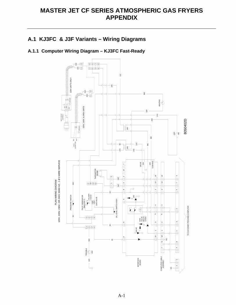
MASTER JET CF SERIES ATMOSPHERIC GAS FRYERS APPENDIX
A-1
A.1 KJ3FC & J3F Variants – Wiring Diagrams A.1.1 Computer Wiring Diagram – KJ3FC Fast-Ready
21
68
13
97
52
79
101
35
42
131414
132
45
31
1096
58
32
712
12
5 6 7 84321
1211109H
I-LIM
ITT'
STAT
PILO
T G
ENER
ATO
R
(M
ILLI
VOLT
)
GAS
VAL
VE
PR
ESSU
RE
SWIT
CH
OIL
LEV
EL S
WIT
CH
ASS
Y
4C
47C
8C
GAS
VALV
ER
ELAY
C
24V
24V
13C
12C
36C
24V
OFF ON
HEA
TIN
G
15P
66C
3C
5 6 7 84321
INTE
RFA
CE
BOAR
D
NC
NC
CO
MPU
TER
CAB
LEAS
SEM
BLY
TO C
UST
OM
ER P
RO
VID
ED C
OM
PUTE
R80
5040
2D
25C
24C
12VD
C
5C
PLA
N W
IRIN
G D
IAG
RA
M
VALV
E24
V
24V
11C
10C
VALV
E
CO
NTR
OL
27C
26C
38C
50/6
0 H
Z., 1
Ø 3
WIR
E S
ERVI
CE
120V
, 220
V, 2
30V
, OR
240
V;
TRO
UBL
E
24V
14C
55C
PR
OBE
THER
MIS
TOR
GR
NBLK WH
T22
C
21C
INP
UT
120V
AC
CO
NTR
OLS
22C
21C
GR
OU
ND
21C
22C
51
21C 5
22C 1
120V
UN
ITS
ON
LY
220V
, 230
V, &
240
V U
NIT
S
GR
OU
ND
FIE
LDC
ON
NE
CTI
ON
BLK
WH
T
54C
9C
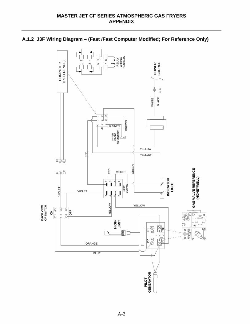
MASTER JET CF SERIES ATMOSPHERIC GAS FRYERS
APPENDIX
A-2
A.1.2 J3F Wiring Diagram – (Fast /Fast Computer Modified; For Reference Only)
BA
CK
VIE
WO
F SW
ITC
H
HONEYWELL 1/2P.S.I.
TH TH
PP
PP
1 2 3
4 65
12
346
578
6
12
34
5
87
RE
LAY
WIR
ING
DIA
GR
AM
CO
MPU
TER
(REF
EREN
CE)
1 2
1 2
J4P
4VI
OLE
T
VIOLET
BLUE
ORANGE
YELL
OW YELLOW
GR
EE
N
J2
VIOLETRE
D
RE
D
BR
OW
NBROWN
FRYE
RPR
OB
EC
ON
NEC
TOR
HEA
TD
EMA
ND
YELLOW
YELLOWW
HIT
E
BLA
CK
HIG
H-
LIM
IT
PILO
TG
ENER
ATO
R
OFF
IND
ICA
TOR
LIG
HT
ON
GA
S VA
LVE
REF
EREN
CE
(HO
NEY
WEL
L)
POW
ERSO
UR
CE
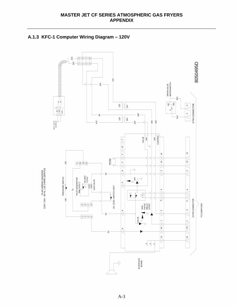
MASTER JET CF SERIES ATMOSPHERIC GAS FRYERS
APPENDIX
A-3
A.1.3 KFC-1 Computer Wiring Diagram – 120V
111
314
132
5
1413
24
53
1109
65
83
27
12
5 6 7 84321
1211109
HI-L
IMIT
T'S
TAT
PIL
OT
GEN
ER
ATO
R
(M
ILLI
VO
LT)
GA
S V
ALVE
PRES
SU
RE
SWIT
CH
OIL
LE
VE
L S
WIT
CH
AS
SY
4C
47C
8C
GA
SV
ALV
ER
ELA
Y
C
120
24V
12V
13C
18C
19C
24V
NC
NO
3C
5 6 7 84321
INTE
RFA
CE
BOA
RD
TO C
OM
PU
TER
8050
495D
12V
DC
5C
PLA
N W
IRIN
G D
IAG
RA
M
VALV
E
24V
24V
120
11C
10C
VAL
VE
CO
NTR
OL
16C
PRO
BE
GR
NBLK
WH
T22
C
21C
INPU
T 12
0V A
CC
ON
TRO
LS
22C
21C
11
15C
14C
7C 4
CD
RA
IN V
ALV
EM
ICR
OS
WIT
CH
36
82C
51C
120V
/ 24
V -
60 H
z, 1
Ø 3
WIR
E S
ER
VIC
E
10
15 P
IN C
ON
NEC
TOR
9 P
IN C
ON
NE
CTO
R
123
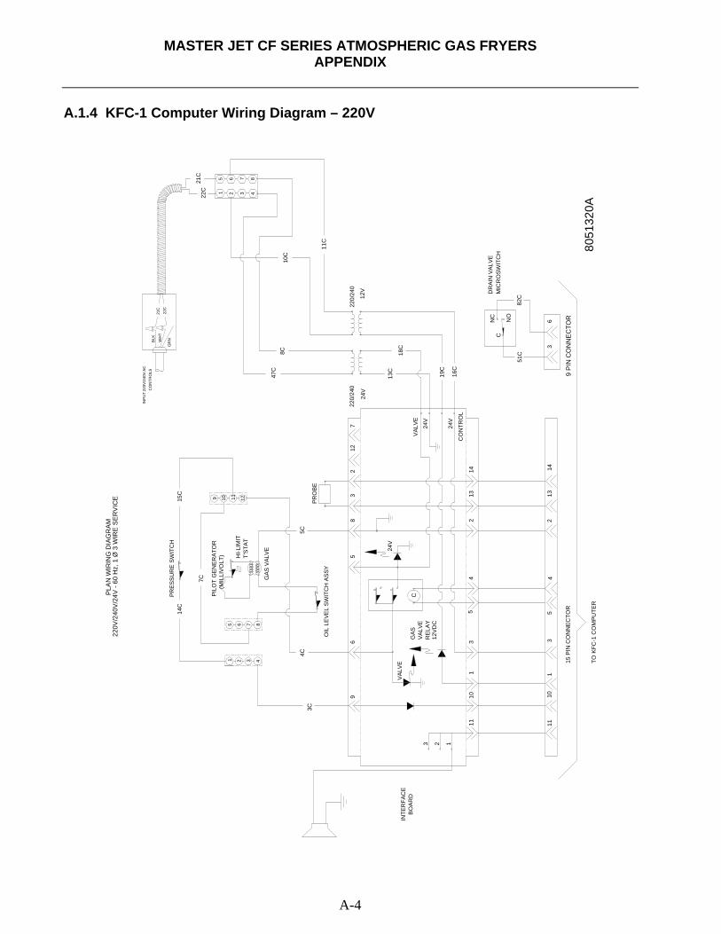
MASTER JET CF SERIES ATMOSPHERIC GAS FRYERS
APPENDIX
A-4
A.1.4 KFC-1 Computer Wiring Diagram – 220V
111
314
132
5
1413
24
53
1109
65
83
27
12
5 6 7 84321
1211109
HI-L
IMIT
T'ST
AT
PILO
T G
ENER
ATO
R
(M
ILLI
VOLT
)
GAS
VAL
VE
PRES
SUR
E SW
ITC
H
OIL
LEV
EL S
WIT
CH
ASS
Y
4C
47C
8C
GAS
VALV
ER
ELAY
C
220/
240
24V
12V
13C
18C
19C
24V
NC
NO
3C
5 6 7 84321
INTE
RFA
CE
BOAR
D
TO K
FC-1
CO
MPU
TER
8051
320A
12VD
C
5C
PLA
N W
IRIN
G D
IAG
RA
M
VALV
E24
V
24V
220/
240
11C
10C
VALV
E
CO
NTR
OL
16C
PRO
BE
GR
NBLK WH
T22
C
21C
INP
UT
220V
/240
V A
CC
ON
TRO
LS
22C
21C
11
15C
14C
7C 4
CD
RAI
N V
ALVE
MIC
RO
SWIT
CH
36
82C
51C
220V
/240
V/2
4V -
60 H
z, 1
Ø 3
WIR
E S
ER
VIC
E
10
15 P
IN C
ON
NEC
TOR
9 P
IN C
ON
NE
CTO
R
123
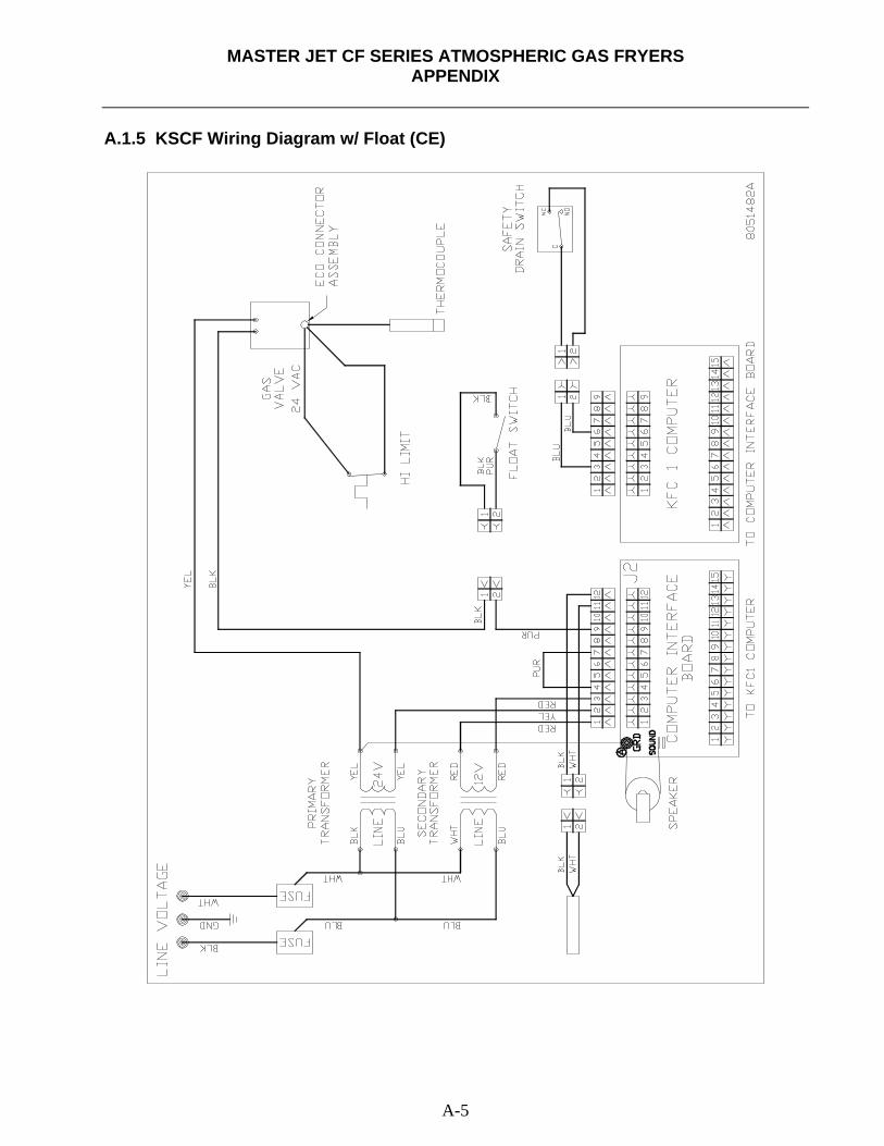
MASTER JET CF SERIES ATMOSPHERIC GAS FRYERS
APPENDIX
A-5
A.1.5 KSCF Wiring Diagram w/ Float (CE)
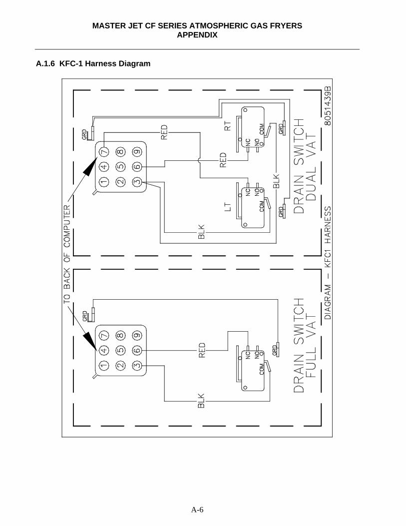
MASTER JET CF SERIES ATMOSPHERIC GAS FRYERS
APPENDIX
A-6
A.1.6 KFC-1 Harness Diagram
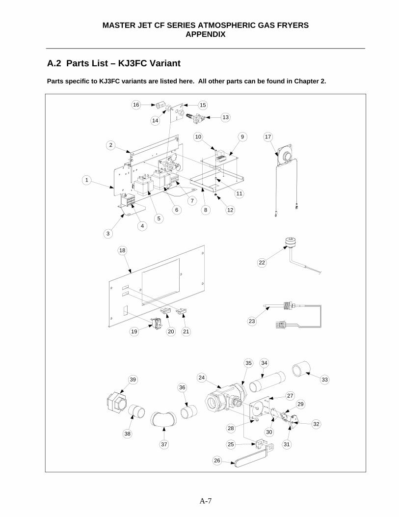
MASTER JET CF SERIES ATMOSPHERIC GAS FRYERS
APPENDIX
A-7
A.2 Parts List – KJ3FC Variant Parts specific to KJ3FC variants are listed here. All other parts can be found in Chapter 2.
1
2
34
56 8
910
11
12
1314
1516
17
23
22
18
19 20 21
24
25
26
27
28
29
30
31
32
33
3435
36
37
38
39
7
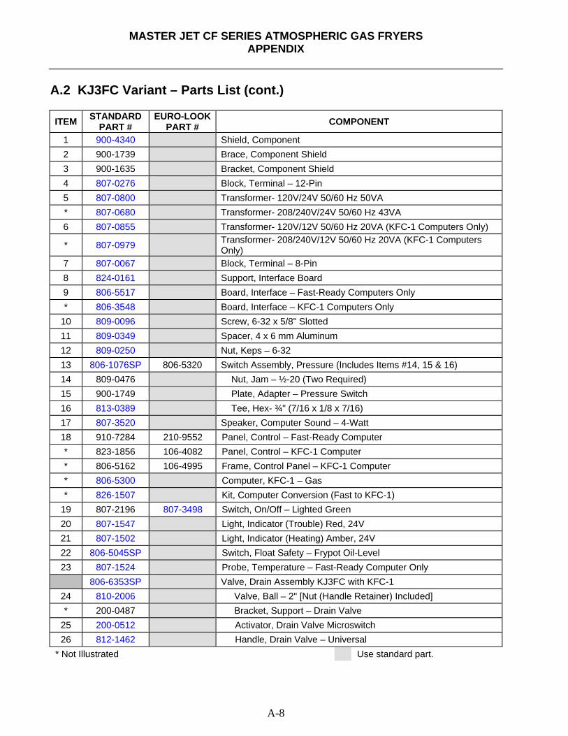
MASTER JET CF SERIES ATMOSPHERIC GAS FRYERS
APPENDIX
A-8
A.2 KJ3FC Variant – Parts List (cont.) ITEM STANDARD
PART # EURO-LOOK
PART # COMPONENT
1 900-4340 Shield, Component 2 900-1739 Brace, Component Shield 3 900-1635 Bracket, Component Shield 4 807-0276 Block, Terminal – 12-Pin 5 807-0800 Transformer- 120V/24V 50/60 Hz 50VA * 807-0680 Transformer- 208/240V/24V 50/60 Hz 43VA 6 807-0855 Transformer- 120V/12V 50/60 Hz 20VA (KFC-1 Computers Only)
* 807-0979 Transformer- 208/240V/12V 50/60 Hz 20VA (KFC-1 Computers Only)
7 807-0067 Block, Terminal – 8-Pin 8 824-0161 Support, Interface Board 9 806-5517 Board, Interface – Fast-Ready Computers Only * 806-3548 Board, Interface – KFC-1 Computers Only
10 809-0096 Screw, 6-32 x 5/8" Slotted 11 809-0349 Spacer, 4 x 6 mm Aluminum 12 809-0250 Nut, Keps – 6-32 13 806-1076SP 806-5320 Switch Assembly, Pressure (Includes Items #14, 15 & 16) 14 809-0476 Nut, Jam – ½-20 (Two Required) 15 900-1749 Plate, Adapter – Pressure Switch 16 813-0389 Tee, Hex- ¾" (7/16 x 1/8 x 7/16) 17 807-3520 Speaker, Computer Sound – 4-Watt 18 910-7284 210-9552 Panel, Control – Fast-Ready Computer * 823-1856 106-4082 Panel, Control – KFC-1 Computer * 806-5162 106-4995 Frame, Control Panel – KFC-1 Computer * 806-5300 Computer, KFC-1 – Gas * 826-1507 Kit, Computer Conversion (Fast to KFC-1)
19 807-2196 807-3498 Switch, On/Off – Lighted Green 20 807-1547 Light, Indicator (Trouble) Red, 24V 21 807-1502 Light, Indicator (Heating) Amber, 24V 22 806-5045SP Switch, Float Safety – Frypot Oil-Level 23 807-1524 Probe, Temperature – Fast-Ready Computer Only
806-6353SP Valve, Drain Assembly KJ3FC with KFC-1 24 810-2006 Valve, Ball – 2" [Nut (Handle Retainer) Included] * 200-0487 Bracket, Support – Drain Valve
25 200-0512 Activator, Drain Valve Microswitch 26 812-1462 Handle, Drain Valve – Universal
* Not Illustrated Use standard part.
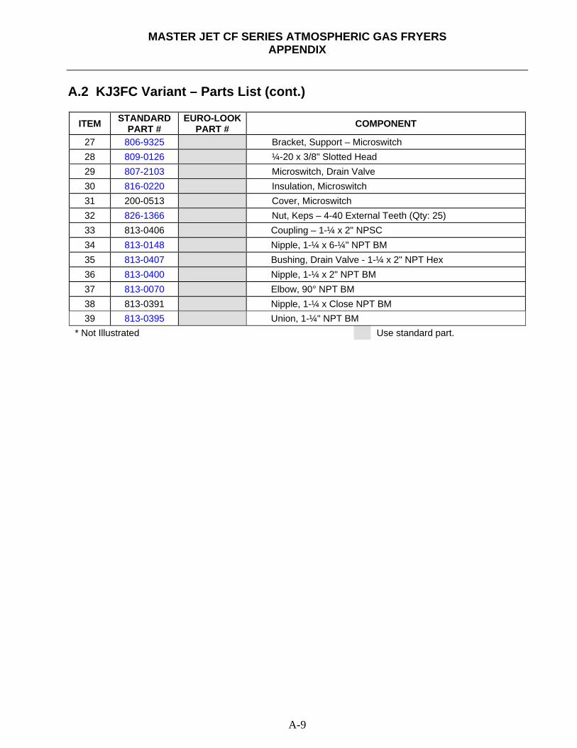
MASTER JET CF SERIES ATMOSPHERIC GAS FRYERS
APPENDIX
A-9
A.2 KJ3FC Variant – Parts List (cont.)
ITEM STANDARD PART #
EURO-LOOKPART # COMPONENT
27 806-9325 Bracket, Support – Microswitch 28 809-0126 ¼-20 x 3/8" Slotted Head 29 807-2103 Microswitch, Drain Valve 30 816-0220 Insulation, Microswitch 31 200-0513 Cover, Microswitch 32 826-1366 Nut, Keps – 4-40 External Teeth (Qty: 25) 33 813-0406 Coupling – 1-¼ x 2" NPSC 34 813-0148 Nipple, 1-¼ x 6-¼" NPT BM 35 813-0407 Bushing, Drain Valve - 1-¼ x 2" NPT Hex 36 813-0400 Nipple, 1-¼ x 2" NPT BM 37 813-0070 Elbow, 90° NPT BM 38 813-0391 Nipple, 1-¼ x Close NPT BM 39 813-0395 Union, 1-¼" NPT BM
* Not Illustrated Use standard part.

THIS PAGE INTENTIONALLY LEFT BLANK

Shipping Address: 8700 Line Avenue, Shreveport, Louisiana 71106
TEL 1-318-865-1711 FAX (Parts) 1-318-688-2200 FAX (Tech Support) 1-318-219-7135
PRINTED IN THE UNITED STATES SERVICE HOTLINE
1-800-551-8633 819-5186
MAR 2011