mason engineering inc., radio receiver with - crypto museum
TRANSCRIPT

p., .A-3B - MM - 1/76
PIU
p i R A D I O R E C E I V E R W I T H S P E C T R U M D I S P L A YV MODEL A-3Bpi
p i ' '
p i ; .
p i[ I .piVPIDpi
P i . . .
p]I • • *F1 0 1976 - F. G. MASON ENGINEERING, INC., FAIRFIELD, CONNECTICUT, USA
p|

111111111111111
1

131
^1
IMPORTANT NOTICE
IT IS IMPORTANT TO NOTE THAT THIS EQUIPMENT CONTAINS
INTERNAL VOLTAGE WHICH MAY BE HAZZARDOUS. MAINTENANCE
AND INSPECTION SHOULD ONLY BE PERFORMED BY QUALIFIED
TECHNICAL PERSONNEL UTILIZING PROPER SAFEGUARDS. REFER
TO THE WARNING LABEL SHOWN BELOW:
^ i
pi
£1
p i
p i
WARNINGO O
r
11
PS 10, 11 & 12 CASE

1 ^
F^J
155!
fm
ra
l™S

*4i " > . A 3 B - M M - 5 / 7 1 P a g e T C - 1
* *■ T A B L E O F C O N T E N T S P a g e N o .
p P A R T O N E : G E N E R A L D E S C R I P T I O N1 . 1 D e s c r i p t i o n o f A 3 B R e c e i v e r S y s t e m 1 - 1
p , 1 . 2 M o d e s o f O p e r a t i o n 1 - 1! 1 . 3 C o m p o n e n t s a n d T h e i r F u n c t i o n s 1 - 1
1 . 4 P h y s i c a l C h a r a c t e r i s t i c s 1 - 2p i
pi
pi
pi
Ipsl
0piDp)
p iup]upi
piucpi)D
PART TWO: DESCRIPTION OF ACCESSORIES
2 . 1 A c c e s s o r i e s D e s c r i p t i o n . 2 - 1

1A 3 B - M M - 5 / 7 1 P a g e T C - 2 ^
T A B L E O F C O N T E N T S . P a g e N o . < *
PART THREE: ELECTRICAL SPECIFICATIONS - RECEIVER MODES ^
3 . 1 R a d i o F r e q u e n c y C o v e r a g e S " 13 . 2 A M S e n s i t i v i t y 3 ' " 1 * 13 . 3 F M Q u i e t i n g 3 ~ x3 . 4 I F B a n d w i d t h s 3 " * 13 . 5 B a n d w i d t h S l o p e F a c t o r S " * 1 T3 . 6 S p u r i o u s R e s p o n s e R e j e c t i o n 3 - 2 J3 . 7 O s c i l l a t o r R a d i a t i o n 3 " * 23 . 8 A n t e n n a I n p u t I m p e d a n c e • 6 ~ *3 . 9 F M D e t e c t i o n 3 ~ 2 J3 . 1 0 B F O 3 " 2 _3 . 1 1 A u d i o O u t p u t d " z3 . 1 2 D i a l s 3 " 2 J3 . 1 3 I F O u t p u t 3 ~ 33 . 1 4 P o s t D e t e c t i o n O u t p u t 3 ~ 3 j3 . 1 5 S i g n a l S t r e n g t h M e t e r 3 " 3 J3 . 1 6 B a t t e r y S u p p l y 3 ~ 33 . 1 7 A C P o w e r S u p p l y 3 ~ 3 |3 . 1 8 O s c i l l a t i o n s 3 " 33 . 1 9 C W D e s e n s i t i z a t i o n 3 ~ 43 . 2 0 O p e r a t i n g T e m p e r a t u r e . 3 ~ 4 13.21 Bandspread
(SB$
c^ji
1

WH
13
A3B-MM-5/71 Page TC-3
T A B L E O F C O N T E N T S P a g e N o .
PART FOUR: ELECTRICAL SPECIFICATIONS-VISUAL DISPLAY MODES
4 . 1 D i s p e r s i o n a n d C a l i b r a t i o n 4 - 14 . 2 F r e q u e n c y L i n e a r i t y 4 - 14 . 3 R e s o l u t i o n 4 - 14 . 4 S w e e p R a t e C a l i b r a t i o n 4 - 14 . 5 S w e e p L i n e a r i t y 4 - 14 . 6 A u d i o L i m i t a t i o n i n S p e c t r u m M o d e 4 - 14 . 7 S c r e e n S i z e 4 - 14 . 8 S i g n a l G a i n C o n t r o l 4 - 24 . 9 S e n s i t i v i t y . . 4 - 24 . 1 0 D y n a m i c R a n g e 4 - 24 . 1 1 S p u r i o u s R e s p o n s e 4 - 24 . 1 2 V i d e o B a n d w i d t h 4 - 24 . 1 3 P h o s p h o r 4 - 24 . 1 4 T u n e r S w e e p M o d e 4 - 24 . 1 5 S c o p e M o d e 4 - 2
[CT$|

A3B-MM-5/71 Page TC-4 1T A B L E O F C O N T E N T S P a g e N o . J
P A R T F I V E : ' T H E O R Y O F O P E R A T I O N 1
5 . 1 I N T R O D U C T I O N 5 - 15 . 2 H I G H F R E Q U E N C Y R E C E I V E R ( 3 0 1 0 0 - . 3 t o 1 6 0 0 M H z ) 5 - 1 ]5 . 2 . 1 1 1 1 M H z t o 2 3 . 5 M H z C o n v e r t e r 5 - 15 . 2 . 2 B a n d w i d t h D e t e r m i n a t i o n 5 - 15 . 2 . 3 2 3 . 5 M H z I F A m p l i fi e r 5 - 15 . 2 . 4 A M D f e t e c t o r 5 - 1 J5 . 2 . 5 F M D e t e c t o r 5 - 25 . 2 . 6 S i g n a l S t r e n g t h M e t e r 5 - 25 . 2 . 7 A u d i o A m p l i fi e r 5 - 25 . 2 . 8 S w e e p A m p l i fi e r 5 - 25 . 3 H I G H F R E Q U E N C Y T U N E R S * ' 5 - 25 . 3 . 1 T u n e r T A 3 - 1 ( . 3 - 1 M H z ) 5 - 35 . 3 . 2 T u n e r T A 3 - 2 ( 1 - 3 . 5 M H z ) 5 - 35 . 3 . 3 T u n e r T A 3 - 3 ( 3 . 5 - 1 2 M H z ) 5 - 3 j5 . 3 . 4 T u n e r T A 3 - 4 ( 1 2 - 4 3 M H z ) 5 - 35 . 3 . 5 T u n e r T A 3 - 5 ( 4 3 - 1 3 0 M H z ) 5 - 4 _5 . 3 . 6 T u n e r T A 3 - 6 ( 1 3 0 - 4 2 0 M H z ) 5 - 45 . 3 . 7 T u n e r T A 3 - 7 ( 4 2 0 - 8 0 0 M H z ) 5 - 45 . 3 . 8 T u n e r T A 3 - 8 ( 8 0 0 - 1 6 0 0 M H z ) 5 - 4 „5 . 4 L O W F R E Q U E N C Y R E C E I V E R ( 3 0 2 0 0 - 2 t o 3 0 0 K H z ) 5 - 5 ]5 . 4 . 1 T A 3 - 0 3 B T u n e r 5 - 55 . 4 . 2 S w e p t C o n v e r t e r ( C - 2 ) 5 - 5 «5 . 4 . 3 B a s i c L o w F r e q u e n c y U n i t ( B - 2 ) 5 - 6 ]5.4.3.1 455 KHz Amplifier, Emitter Follower and Bandpass Filter 5-65 . 4 . 3 . 2 4 5 5 K H z A m p l i fi e r S t r i n g , A M D e t e c t o r a n d S M e t e r 5 - 6 r ^5 . 4 . 3 . 3 V i d e o D e t e c t o r 5 - 65 . 4 . 3 . 4 F M L i m i t e r a n d D e t e c t o r 5 - 65 . 4 . 3 . 5 A u d i o A m p l i fi e r 5 - 6 ^5 . 4 . 3 . 6 4 5 5 K H z B e a t F r e q u e n c y O s c i l l a t o r 5 - 75 . 5 V I S U A L D I S P L A Y U N I T ( S - 3 ) 5 - 75 . 5 . 1 S a w t o o t h S w e e p G e n e r a t o r 5 - 7 ^5 . 5 . 2 V e r t i c a l A m p l i fi e r 5 - 75 . 5 . 3 H o r i z o n t a l A m p l i fi e r 5 - 75 . 6 A C P O W E R S U P P L Y P S - 1 0 5 - 8 ^5 . 7 B A T T E R Y P A C K A S S E M B L Y B P - 7 5 - 8
B ^ l

f fl
pii
PI
i
p31
6.16.26 .3
I 6 .416.56.6
|H 6 .7]1 6.8
pi
PI
_ 7.1
j
7.27.3
- 7.4
p i7.57.6
- 7.7
pii
7.87.97.10
j
7.117.12! 7.13
$37.147.15
- 7.16JH
7.17
A3B-MM-5/71 Page TC-5
T A B L E O F C O N T E N T S P a g e N o .
PART SIX: OPERATING PROCEDURE
L o w F r e q u e n c y R e c e i v e r M o d e 6 - 1H i g h F r e q u e n c y R e c e i v e r M o d e 6 - 1P a n a d a p t e r M o d e 6 - 2T u n e r S c a n n i n g M o d e 6 - 5D o u b l e D e t e c t M o d e 6 - 6V i d e o M o d e 6 - 8R e m o t e T u n e r M o d e 6 - 9O s c i l l o s c o p e M o d e 6 - 9
PART SEVEN: REPAIR AND ALIGNMENT OF COMPONENT PARTS
S c o p e 7 - 1B - l H F R M a i n C h a s s i s 7 - 2C - l 1 1 1 t o 2 3 . 5 M H z C o n v e r t e r 7 - 5T A 3 - 1 T u n e r ( . 3 - 1 M H z ) 7 - 7T A 3 - 2 T u n e r ( 1 - 3 . 5 M H z ) 7 - 9T A 3 - 3 T u n e r ( 3 . 5 - 1 2 M H z ) 7 - 1 1T A 3 - 4 T u n e r ( 1 2 - 4 3 M H z ) 7 - 1 3T A 3 - 5 T u n e r ( 4 3 - 1 3 0 M H z ) 7 - 1 5T A 3 - 6 T u n e r ( 1 3 0 - 2 2 0 , 2 2 0 - 4 2 0 M H z ) 7 - 1 6T A 3 - 7 T u n e r ( 4 2 0 - 8 0 0 M H z ) 1 - & 9 .T A 3 - 8 T u n e r ( 8 0 0 - 1 6 0 0 M H z ) 7 - 2 1 .B - 2 L F R M a i n C h a s s i s 7 - ! 2 3C 2 2 3 . 5 M H z t o 4 5 5 K H z C o n v e r t e r 7 - 2 5T A 3 - 0 3 B T u n e r ( 2 - 3 0 0 K H z ) 7 - 2 7S - 3 V i s u a l D i s p l a y U n i t 7 - 2 9P S - 1 0 A C P o w e r S u p p l y 7 - 3 1B P - 7 B a t t e r y P a c k 7 - 3 2

fm§
A3B-MM-9/71 Page TC-6
TABLE OF CONTENTS Page No.
PART EIGHT: OPERATIONAL TESTS, RECEIVER MODES
8.1 AM Sensitivity and Dial Accuracy8 .2 FM Qu ie t i ng8.3 Bandspread (Fine Tune)8.4 IQP Rejection8.5 Image Rejection8.6 Oscil lator Radiation8. 7 IF Bandwidths8.8 Sweep Width8.9 Sweep Rate8.10 S3 Vertical Sensitivity8.11 Signal Gain Control8.12 Video Bandwidth8.13 Z Axis Sensitivity8.14 Brightness Control8.15 Focus Control8.16 Sweep Centering Control8.17 Signal Centering Control8.18 Sync Control8.19 External Sync Jack8.20 Sweep Gain Control8.21 LFR Hi-Low Meter Switch8.22 LFR IF Gain Control8.23 LFR AGC Test Jack8.24 LFR Detect out Jack8.25 LFR Audio Output8.26 LFR IF Out Jack8.27 LFR BFO Test8.28 HFR Hi-Low Meter Switch8.29 HFR IF Gain Control,8.30 HFR AGC Test Jack8.31 HFR Detect Output and Swp Jack8.32 HFR Audio Output8.33 HFR BFO Test8.34 BP7 Battery Pack Test8.35 Accessory Check
NOTE: PART NINE incorporated into Part 8 9/71)
8-1fawtg
8-28-3 J
8-3 B B
8-38-38-4 t m8-58-68-6 en
8-68-68-6 rs5
8-78-78-7 «■8-78-78-7 (8-78-78-88-8
} v m
8-88-8 ns8-88-88-8 fa.
8-98-98-9 «8-98-98-9 Braj
8-9 -
1-]v-^i

s
TABLE OF CONTENTS
PART TEN: OPERATING DIAGRAM
10.1 Operat ing Diagram
A3B-MM-5/71 Page TC-7
Page No.
10-1
PART ELEVEN: SCHEMATIC WIRING DIAGRAMS
p*J
Figure Title Drawing No.
11.1 Block Diagram A3 System 30000-x11.2 Bl/Cl Basic Unit (High Freq. Receiver) SWD 4048 D11.3 T A 3 - 1 T u n e r ( " »t- . t t \ SWD 4023 B11.4 T A 3 - 2 T u n e r ( " t» t t \ SWD 4024 B11.5 TA 3 - 3 T f U n e r ( " n t t \ SWD 4025 B11.6 T A 3 - 4 T u n e r ( " t t " ^ SWD 4026 B11.7 T A 3 - 5 T u n e r ( " f t t t \ SWD 4027 B11.8 T A 3 - 6 T u n e r ( " f t t t \ SWD 4028 C11.9 TA 3 - 7 Tu n e r ' ( " t t " \ SWD 4046 C11.10 T A 3 - 8 T u n e r ( " t t t t \ SWD 4047 C11.11 SB1 Switch Board ( " t t " ) SWD 4056 C11.12 B2 Basic Uni t (Low Freq. Receiver) SWD 4031 B11.13 C2 Swept Converter (" t t t t \ SWD 4033/35 C11.14 TA3-03B Tuner ( " f t f t \ SWD 4073 B11.15 Vert. Amp. and Sawtooth Sweep Gen. S3 Monitor SWD 4038 C11.16 Horz, Amp. S3 Monitor SWD 4039 C11.17 High Voltage Divider S3 Monitor SWD 4042 B11.18 PS10 AC Power Supply SWD 4074 B11.19 High Voltage Converter S3 Monitor SWD 4077 B

A3B-MM-5/71 Page TC-8
TABLE OF CONTENTS
PART TWELVE: PICTORIAL WIRING AND ASSEMBLY DIAGRAMS
Figure12.112.212.312.4
12.512.612.712.812.912.1012.1112.1212.1312.1412.1512.1612.1712.1812.1912.2012.2112.2212.2312.2412.2512.2612.2712.2812.2912.3012.3112.3212.3312.3412.3512.3612.3712.3812.3912.4012.4112.4212.43
Ti t l eHarness, InterconnectingHigh Frequency Receiver Assembly
» " " S w i t c h B o a r d A s s e m b l y» " " B a s i c U n i t B l / C l - 1
TA3-1 AssemblyTA3-1 RF Cover AssemblyTA3-1 PC Board AssemblyTA3-2 AssemblyTA3-2 RF Cover AssemblyTA3-2 PC Board AssemblyTA3-3 AssemblyTA3-3 RF Cover AssemblyTA3-3 PC Board AssemblyTA3-4 AssemblyTA3-4 RF Cover AssemblyTA3-4 PC Board AssemblyTA3-5 AssemblyTA3-5 RF Cover Assembly
" TA3-5 PC Board Assembly" TA 3 - 6 A s s e m b l y
IF Preamp TA3-6RFAmp. TA3-6High Frequency Receiver Tuner TA3-7 Assembly
t t t t » i f P C B o a r d A s s e m b l yt t t t » T u n e r T A 3 - 8 A s s e m b l y
Low Frequency Receiver Assembly455 KHz IF PC Board Ass'y B2-1Audio/BFO PC Board Ass'y B2-2Panel AssemblyWiring AssemblySwept Converter PC Board Ass'ySwept Converter PC Board Ass'ySwept Converter PC Board Ass'yTuner TA3-03B AssemblyTuner TA3-03B PC Board Ass'y
Visual Monitor Assemblyf t t » s - 3 F r o n t C o v e r A s s e m b l yt t » » Ve r t i c a l A m p . P C B o a r d A s s e m b l y» » H o r i z o n t a l A m p . P C B o a r d A s s e m b l y
H. V. Converter S3 MonitorPower Supply PS-10 Assembly
t t t t PS-10 High Vol tage Board AssemblyBattery Pack BP-7 Assembly
Drawing No.6811-D30100-D30102PWD 30106-lx(3 Pages)30110-C30116-BPWD 4023-D30115-C30117-BPWD 4024-C30120-C30118-BPWD 4025-C30125-C30119-BPWD 4026-D30130-CPWD 30133-BPWD4027-C30135-DPWD 4068-B30139-B30140-DPWD 4029-B30150-D30200-DPWD 4031-DPWD 4032-CPWD 30215PWD 30205
C2-1 PWD4033-CC2-2 PWD 4034-CC2-3 PWD 4035-C
30250-DPWD 4073-C30300-C30310-DPWD 4038-CPWD 4039-CPWD 4077-C30410-DPWD 4074-C30460
n
i^jj

Wft
BPJ
13.11SI
. 13.213.3
w\ 13.4_ 13.5
ml
W)
IBi)
l ^ H
A3B-MM-5/71 Page TC-9
TABLE OF CONTENTS
PART THIRTEEN: TEST SET UP DIAGRAMS
RF Coverage, AM Sensitivity, FM Quieting, Spurious Response RejectionDial Calibration, % Distortion, Signal MeterIF Bandwidths, Slope Factor, FM discriminator, BandspreadSpurious ResponsePower SupplyCW Desensitization
PART FOURTEEN: TEST DATA FORMS
T i t l e D a t a S h e e t
S e n s i t i v i t y a n d D i a l A c c u r a c y AQuieting, Sweep Width, IF Rejection, Image Rejection,
L . O . R a d i a t i o n , A G C T e a t s BI F R e s p o n s e c u r v e s , A u d i o , B F O S w e e p - W i d t h Te s t s CM i s c e l l a n e o u s T e s t s B
«¥l

(^
I ' l l
J
( ^ 1
i™ |

w
F?
A3B-MM-5/71 Page 1-1
PART ONE:, GENERAL DESCRIPTION
1.1 DESCRIPTION OF A-3B RECEIVER SYSTEM:
The model A-3B Radio Receiver is a portable, miniature, wide frequencycoverage instrument with visual display having versatile signal reception,processing and read out functions. The low and high frequency units areusable separately as receivers and the visual display unit is usable as autility oscilloscope. Together, in various combinations, they are usablein the modes described in Paragraph 1.2. It differs somewhat from theoriginal A-3, mainly concerning the AC power supply (PS-10) and theS3 monitor.
1.2 MODES OF OPERATION:
1.2.1 Receiver Mode: Both the low and the high frequency receiver andpower supply are usable as a straight receiver with audio and "S" meteroutputs.
1.2.2 Double Detect Mode: Detected output of high frequency receiveris fed to input of low frequency receiver for second detection.
1.2.3 Panadapter Mode: A converter is provided to permit use of thelow frequency IF unit and signal analyzer in a conventional "Pan-Adapter"mode. RF coverage in this mode is . 3 to 1600 MHz. Simultaneous audioana spectrum display "readouts" are possible in this mode.
1.2.4 Tuner Scanning Mode: The visual display unit used with eitherreceiver provides uncalibrsted spectrum display outputs. Audio andvisual outputs are not to be monitored simultaneously in this mode.
1.2.5 Video Mode: The visual display unit is usable to display thedetected output of either receiver.
1.2. 6 Oscilloscope Mode: The visual display unit is usable separatelyas a Utility Oscilloscope.
1.2. 7 All of the above modes are operable without removing any componentsfrom the carrying case.
1.2.8 Remote Tuner Operation: Individual tuners may be removed andcable connected with receiver to allow remote tuner operation.
1, 3 COMPONENTS AND THEIR FUNCTION:
1.3.1 High Frequency Receiver: This receiver provides signal receptionfrom . 3 to 1600 MHz and processes the signal through amplification, filtering,

i A 3 - M M - 5 / 7 1 P a g e 1 - 2
detection-to-Audio and signal meter read-out. This unit also provides outputsfor double detect and visual displays as per Paragraph 1.2.2 to 1.2.5. Thisunit consists of eight (8) tuning: heads, 23.5 MHz IF amplifier with selectable _ |filters, 111/23.5 MHz converter, AM, and FM detectors, BFO, audio amplifier | ja n d s i g n a l s t r e n g t h m e t e r . T t H n e f l n n f n r m t a - i m o n n w o r a m n « / > a ' [and signal strength meter. It does not contain a power source.
ra |1.3.2 Low Frequency Receiver: This receiver provides signal reception from2 to 300 KHz and processes the signal through amplification, filtering, detection-to-audio and signal meter read-out. This unit also provides for double detection R land visual displays as per Paragraphs 1.2.2 to 1; 2.5. The unit consists ofone tuning head, 455 KHz IF amplifier with selectable filters, AM and FMdetectors, BFO, audio amplifier, signal meter and 23.5/. 455 MHz voltagetunable converter for panadapter mode. This unit does not contain a powersource.
1.3.3 Battery Pack: Two battery packs are provided containing easilyreplaceable batteries. These packs are capable of providing power to anyone or all of the two receivers and visual display unit.
1.3.4 AC Power Supply: This unit supplies any one or all of the tworeceivers and visual display unit from a 115V - 20V or 230V - 30V 50 to 60Hertz AC line. The AC power supply also contains the power line antenna circuit.
1.3.5 Accessories: Accessories include antennas, cables, carrying case,manuals, tools, attenuators, etc.
L 3.6 Visual Display Unit: The visual display unit provides CRT read-out, «qassociated horizontal, vertical and power conversion circuitry needed to 1process receiver output for frequency spectrum and video display. In addition,the unit provides ramp generator output with appropriate bias voltage to drive mvoltage tunable oscillators in the receiver sections.
1.4 PHYSICAL CHARACTERISTICS:
|0tm{j
1.4.1 Case: All components are carried in a 12" x 17" x 6" case exceptfor the maintainence manual.
1.4.2 Weight: Weight is less than 32 pounds with batteries.
1.4.3 Configuration: All units are operable in the case with all controls, jacks,dials and read-outs in the horizontal plane except the visual display unit whichis in the lid of the case with a vertical plane panel. The display screen imageappears in this vertical plane. Inter connecting cables are used to facilitatevarious modes of operation.

w
r
i p p l
A3-MM- 5/71 Page 1-3
1.4.4 All controls and connectors are clearly and permanently marked.Each tuning head is marked indicating frequency range.
1.4.5 IF output frequencies are marked near IF output BNC connectors.
1.4.6 The gain control positions are graduated to indicate position.
1.4.7 All receiver and visual display unit markings are exposed whenunits are stored in the attache' case with the lid open.
1.4.8 The battery pack schematic diagram, together with substitutionbattery types and voltages, are displayed on the battery pack.
1.4.9 All screws are locked with break-away adhesive (such as Loctite).This, however, does not preclude the removal of same for equipment repair.
«9

A3B-MM-ll/76Page 2-1
PART TWO: DESCRIPTION OF ACCESSORIES
2.1 ACCESSORIES
The following accessories are provided.
I t e m Q u a n t i t y2 . 1 . 1 E a r p h o n e w i t h c o r d 12 . 1 . 2 W h i p A n t e n n a 12 . 1 . 3 B o w T i e A n t e n n a w i t h e x t e n d e r s 12 . 1 . 4 F e r r i t e R o d A n t e n n a # 1 ( 2 - 3 0 0 K H z ) 12 . 1 . 5 F e r r i t e R o d A n t e n n a # 2 ( ; 3 - 3 0 M H z ) 12 . 1 . 6 L o n g W i r e A n t e n n a 12 . 1 . 7 B l o c k i n g C a p a c i t o r 12 . 1 . 8 2 0 d B A t t e n u a t o r P a d 22 . 1 . 9 B N C M a l e / M a l e a d a p t e r 12 . 1 . 1 0 B N C F e m a l e / F e m a l e a d a p t e r 12 . 1 . 1 1 E u r o p e a n P o w e r p l u g a d a p t e r # 1 12 . 1 . 1 2 E u r o p e a n P o w e r p l u g a d a p t e r # 2 12 . 1 . 1 3 F i v e f o o t B N C c a b l e 12 . 1 . 1 4 O n e f o o t B N C c a b l e 12 . 1 . 1 5 P o w e r C a b l e 12 . 1 . 1 6 R e m o t e T u n e r C a b l e 12 . 1 . 1 7 M a n u a l 12 . 1 . 1 8 T o o l , c o m m o n s c r e w d r i v e r 12 . 1 . 1 9 T o o l , P h i l l i p s S c r e w d r i v e r 12 . 1 . 2 0 A l l e n w r e n c h 12 . 1 . 2 1 S p l i n e K e y !2 . 1 . 2 2 A t t a c h e C a s e 12 . 1 . 2 3 A t t a c h e C a s e i n s e r t # 1 L o w e r 12 . 1 . 2 4 A t t a c h e C a s e i n s e r t # 2 L i d , l a r g e 12 . 1 . 2 5 A t t a c h e C a s e i n s e r t # 3 L i d , s m a l l 12 . 1 . 2 6 A t t a c h e C a s e i n s e r t # 4 ( S 3 P a d s ) 22 . 1 . 2 7 I n t e r c o n n e c t i n g h a r n e s s 12 . 1 . 2 8 S p i n n e r k n o b *2 . 1 . 2 9 A C 3 w i r e t o 2 w i r e a d a p t e r 1
11 ^
C^^

3.1
A3B-MM-12/74 Page 3-1
PART THREE: ELECTRICAL SPECIFICATIONS RECEIVER MODE
Radio Frequency Coverage:2 KHz to 1600 MHz
ppi
p i
3.2 AM Sensitivity:
psi 3.3
p i
us
sxr IF BW M lix. Input For Output of2 KHz - 80 KHz 200 Hz 1. 5 uv (CW) 25% S Meter
80 KHz - 300 KHz.3 - 130 MHz
2 KHz20 KHz
1.1.
5 uv*5 uv*
Deflection10 dB of S+N
" N130 - 400 MHz 20 KHz' • 2. 0 uv* u400 - 800 MHz 90 KHz 2. 5 uv* i t
800 - 1600 MHz 90 KHz 3. 5 uv* t t* Input signal 30% amplitude modulated with 1000 Hz signal.
FM Quieting: Max. Input for
RF IFBW20 dB of AudioOutput Quieting2 * 5 KHz
5 - 300 KHz(FM Inoperable)
2 KHz 3 uv.3 -12 MHz 20 KHz 5 uv12 - 400 MHz 90 KHz 7 uv
400 - 800 MHz 90 KHz 10 uv800 - 1600 MHz 90 KHz 15 uv
3.4 IF Bandwidths Selectable:
RF2 5 KHz5 - 1 5 KHz
15 - 300 KHz.3 1 MHz*1 - io:< MHz*
10 -1600 MHz*
Bandwidth At - 6 dB Points.2 KHz.2 and 2 KHz.2, 2, and 10 KHz2 and 20 KHz2, 20, and 90 KHz2, 20, 90, and 1000 KHz* These RF ranges also have . 2 and 10 KHz available by using converter
located in the LF Receiver although usability is limited by L. O. stability.It should further be noted that full IF bandwidths may not be realized at all *RF's because of narrow RF selectivity.
3.5 Bandwidth Slope Factor:
The slope factor; bandwidth at;;50f dB point divided by bandwidth at 6 dB point,is 2.6:1 or less, except in 1 MHz position.

A3B-MM-l2/74Page 3-2
3.6 Spurious Response Rejection:
All spurious response rejections, including IF and Image, and internallygenerated signals, are as follows:
. R F M i n i m u m R e j e c t i o n2 - 3 0 0 K H Z 5 0 d B
. 3 - 1 2 k . M H z 8 0 d B1 2 - 1 3 a M H z 5 0 d B
1 3 0 - 1 6 0 0 M H z 4 0 d BNote: Rejection levels are measured to.an RF level reference of 3 uv or less.
3.7 "Local Oscillator Radiation:
Local oscillatior voltage level measured at the antenna terminal is less than-60 DBM for RF of 2KHz to 130 MHz and less than -50 DBM for RF of 130 to1200.
3.8 Antenna Input Impedance:
50 ohms nominal.
3.9 FM Detection:
FM discriminators are provided for all frequencies from 5 KHz to 1600 MHz,however, in the 200 Hz bandwidth position of the low frequency receiver andthe 2 KHz bandwidth position of the high frequency receiver, the discriminatorsmay not be usable.
3.10 BFO:
A crystal controlled BFO is provided in the HF receiver which also acts asa center marker for the panadapter mode. A tunable BFO is provided for the jLF receiver.
3.11 Audio Output:Audio output level is 6.5 mw minimum undistorted output into a 1000 ohm load.Harmonic distortion is less than 3%. For this measurement, the input is a 30 uvsignal, 30% amplitude modulated by 1 KHz. Receiver is set in AM, with manualIF gam set for red l&te on '«" meter (LO S-meter range) and AF gain set for ratedoutput (6.5 m^,,lisspeeification does not apply to the 200 Hz IF bandwidthp o s i t i o n . '
3 . 1 2 D i a l : / " 1Dials are direct reading and have an accuracy of plus or minus 1.5% or 1/8 inch jdial displacement whichever is greater. Tuning controls have good positivec o n t r o l w i t h a 1

IP"!
|pff)
A3B-MM-5/71 Page 3-3
maximum of 45 degrees of mechanical backlash.
3.13 IF Output:
Undetected IF output is provided at a bandwidth of 20 KHz minimum for anRF center frequency of 20 KHz to 3 MHz, a bandwidth of 90 KHz minimumfor an RF center frequency of 3 to 40 MHz, and a bandwidth of 2 MHzminimum for an RF center frequency of 40 to 1600 MHz. Bandwidths are
r measured at the 6 dB points. Level is 25 uv for 2 uv input signal.
3.14 Post Detection Output:
One-at-a-time detected IF, AM and FM outputs are provided. (FM detectionsubject to exceptions as noted in Paragraph 3.9).
3.15 Signal Strength Meter:
A signal strength meter indicating relative field strength of all incomingsignals, modulated or unmodulated, is provided with low and high levelswitch. Also, the meter is used to indicate battery and power supplyconditions. A redline is positioned on the meter to indicate the battery orAC power supply cutoff point.
3.16 Battery Supply:
Battery packs are supplied which will operate all units for 25 hours or more.They operate one receiver for over 100 hours. Batteries are held in containers separate from the rest of the receivers to insure against leakage,corrosion, and shorting damage. The equipment is so designed that theconnecting power cable must be removed when case lid is closed to preventaccidental "on" operation while stored. When using the visual display unitwith receivers, use both battery packs to greatly extend operating time. Thisis important and is required to operate panadapter system for over 25 hours.
3.17 AC Power Supply:
An AC power supply for use in lieu of the batteries is supplied with input of115V - 20V or 230V - 30V, 50/60 Hz and provides power for all circuits. TheAC power supply is isolated from the AC power mains to eliminate any possibleshock hazard to user. A power line to antenna input matching circuit is locatedin the AC supply thereby using the same power cord and plug. A BNC jack islocated on the panel for cable connection to the tuners.
m , 3 . 1 8 O s c i l l a t i o n :
The receiver system will not self-oscillate at any dial frequency setting ofany head regardless of input or output loads.
r

Iwj
A3B-MM-5/71 Page 3-4
3.19 CW Desensitizatlon:
Tests for CW desensitization are made according to the procedure outlined in jMil-STD-449C, Procedure 5.3.11. The resulting curve has the following j1s h a p e f a c t o r o r b e t t e r b e t w e e n t h e 1 2 d B a n d 3 0 d B p o i n t s : j
RF range 2 KHz to 5 KHz, less than 3:1 frequency slope, with 12 dB ]points less than 10% of test frequency.
RF range-5 KHz to 1 MHz, less than 3:1 frequency slope, with 12 dBpoints less than 5% of the test frequency;
RF range of 1 to 1600 MHz, less than 6:1 frequency slope, with 12 dBpoints less than 1% of the test frequency.
us;
3.20 Temperature Range:
All components operate from 30 to 122 degrees F except for the battery cells «provided. The operating temperatures of the cells provided are 50 to 122 Jdegrees F.
3.21 Bandspread and/or Fine Tuning:
Bandspread is provided for all RF frequencies. Bandspread range is equalto or more than 0.2% of the RF frequency from 2 KHz to 420 MHz and . 02%from 420 MHz to 1600 MHz.
r^
ami

A3B-MM-5/71. £age 4-1
PART FOUR- ELECTRICAL SPECIFICATIONS-VISUAL DISPLAY MODES
4.1 Dispersion and Calibration:
P " 4 . 1 . 1 P a n a d a p t e r M o d e :*- \ Panadapter mode dispersion is as follows: RF .3 to 12 MHz, 3 selectable
'r dispersions between 2 KHz and 80 KHz. RF 12 MHz to 1600 MHz, 6 selectabledispersions from 2 KHz to 5 MHz. Dispersion in panadapter mode iscalibrated and so marked on the dispersion switch control. At some RFfrequencies, dispersion may be limited by RF selectivity.
4.1.2 Tuner Sweep Mode:— RF 2 to 300 KHz, a maximum of at least 200 KHz dispersion provided. RF| . 3 to 1600 MHz, an uncalibrated tuner sweep mode is supplied.
p?1
r
4.2 Frequency Linearity:
- 8% of dispersion width, applicable in panadapter mode only.
4.3 Resolution:
Panadapter mode analyzer bandwidths are 200 Hz, 2 KHz, and 10 KHz.Selectable.
4.4 Sweep Rate Calibration:
Sweep rates are provided from 1/10 sec/cm to 2 us/cm continuouslyadjustable by overlapping switched ranges and vernier adjust control.Sweep rate versus control setting calibration is so marked on displayunit panel.
4.5 Sweep Time Linearity: .
The sweep time vs. the display spot displacement at calibrated rate positionsis within * 8% of that predicted on the basis of a linear sweep.
4.6 Audio Limitation in Spectrum Mode:
Simultaneous audio and visual outputs are not provided when operating inthe "Tuner Scanning" mode.
4.7 Screen Size;
Display screen is 1" x 3" rectangular.
The visual display unit is capable of use as a utility oscilloscope withspecifications cited in Paragraph 4.4, 4.5, 4.7, 4.8,4.12 and 4.13*Vertical gain is 2 mv/cm. Synchronizing control is provided withexternal/internal switch and jack. Z axis input is also provided.
rztfy
A3B-MM-5/71 Page 4-2
4.8 Signal Gain Control:
Manual signal gain control is provided with 50 dB range.
4.9 Sensi t iv i ty :
Minimum detectable visual output is equal to or less than minimum detectableaudio signal output.
4.10 Dynamic Range:
Signal display unit in panadapter mode is able to display incoming signals of30 dB level differential simultaneously at maximum resolution.
4.11 Spurious Response:
The display is free of signals other than those received at the antennaterminal up to input signal levels of 10 mv.
4.12 Video Bandwidth:
Bandwidth of vertical display amplifier is approximately 1 Hz to 1. 8 MHzat 3 dB points.
4.13 Phosphor:
PI phosphor is used.
4.14 Tuner Sweep Mode:
Circuitry is provided to enable user to spectrum display signals employing «either one of the receivers and the signal display unit in the tuner scanning jmode. (See Paragraph 4. 6 for audio limitation in this mode).
J
r=i|4.15 Scope Mode:
i
1

(uTFI
r
•ml
A3B-MM-5/71 Page 5-1
PART FIVE: THEORY
5.1 INTRODUCTION:
The component parts of the A-3B Receiver System are shown in the blockdiagram of Figure 11-1. The A-3B consists of five (5) basic units: HighFrequency Receiver, Low Frequency Receiver, Visual Display Unit,Battery Pack and AC Power Supply.
5.2 HIGH FREQUENCY RECEIVER: (30100 . 3-1600 MHz)
The High Frequency Receiver is shown schematically in Drawing SWD-4048-D,Figure 11.2. The bandswitch selects the tuner operating in the frequencyrange to be covered and applies DC power to the tuner while simultaneouslycompleting the RF connection between the tuner output and the converter forTuners 4, 6, 7 and 8, or the IF Amplifier in the case of Tuners 1, 2, 3, and5. Refer to drawing SWD-4056C, Figure 11.11 for details of the bandswitch.
5.2.1 111 MHz to 23.5 MHz Converter
The converter mixes the 111 MHz signal with a local oscillator signal fromthe 87.5 MHz crystal controlled oscillator. A band stop filter consistingof L7 and C52 is tuned to 151 MHz to prevent the local oscillator of tunerTA3-4 from entering the converter. A two stage amplifier tuned to 111 MHzsupplies approximately 6 dB gain and the output of the second stage iscoupled to the balance mixer. The 23. 5 MHz signal passes through a lowpass output filter to remove any residual 87.5 MHz signal from the localoscillator. Since Tuners 1, 2, 3 and 5 have outputs at 23. 5 MHz, thepreceeding is not necessary when they are in use. J110 and P110 furnishthe interconnection with the bandswitch.
5.2.2 Bandwidth Determination
Bandwidth is determined by the selection of either the 2 KHz, 20 KHz or 90 KHzcrystal filter by means of the panel mounted four position switch. A fourthposition allows straight through operation with a bandwidth of 1 MHz.
5.2.3 23. 5 MHz IF Amplifier
The IF amplifier consists of transistors Ql through Q5. Ql utilizes a3N140 insulated gate field effect transistor with AGC applied to gate #2.The following four (4) IF stages use 3N128 IGFETS. The interstagetransformers are tunable and have a bandwidth greater than 1 MHz.
5.2.4 AM Detector
AM detection is accomplished by CR4 and CR5. The detected audio is fedthrough S7 to the audio amplifier. The AGC tap furnishes AGC voltage tothe first IF amplifier and the RF stages in Tuners 1, 2, 3 and 4.

TA3-1 .3 to 1 MHzTA3-2 lto3.5 MHzTA3-3 3. 5 to 12 MHzTA3-4 12 to 43 MHzTA3-5 43 to 130 MHzTA3-6 130 to 420 MHzTA3-7 420 to 800 MHzTA3-8 800 to 1600 MHz
(^
«
A3B-MM-5/71 Page 5-2
5.2.5 FM Detector
Q6 and Q7 serve as limiters for the signal. Two discriminators are employed.CR6 and CR7 form a wide band discriminator having a bandwidth of approximately 350 KHz while a crystal discriminator having a bandwidth of 90 KHzis used for narrow bandwidth FM signals. The discriminator to be used isselected with panel switch S6.
5.2.6 Signal Strength Meter
The S Meter gives a signal strength indication for both AM and FM signals.Maximum S Meter excursion may be controlled by the S Meter sensitivityswitch S-3. The S Meter also serves to test the condition of the PS-10 ACPower Supply or the BP-5 battery pack by placing a load (R30) on the voltageterminals of the Power Supply and observing the current drawn through theS Meter. CR3 provides protection in the event the wrong polarity is appliedto the input voltage jack, J15.
5.2.7 Audio Amplifier
A two stage audio amplifier consisting of Q8 and Q9 furnishes a minimum of6.5 mw undistorted output through jack J16. The output impedance is 1000ohms. Audio output volume is adjustable by panel control R31. J
5 . 2 . 8 S w e e p A m p l i fi e r H
The sweep amplifier receives a sweeping voltage through J21 from the Visual „Display Unit. Q10 is also used as an isolation amplifier to prevent the |loading of the sweep generator. After amplification, the sweep voltage isapplied to the local oscillator of the Tuner in use through J113. This will _be covered more completely in Section 5.5 concerning the Visual Display |U n i t . ' J
5 . 3 H I G H F R E Q U E N C Y T U N E R S : ^
f^>
p S t ^ l
iThe tuner to be used is selected by the bandswitch S8 located on the front <^panel of the High Frequency Receiver. The appropriate antenna must be Iconnected to the tuner in use. Power is applied to each tuner through the

SBI
im
Wmf
IfliS)
p |
A3B-MM-5/71 Page 5-3
bandswitch. Only one tuner may be used at a time since the unused localoscillators are disabled to prevent interference to the band being surveyed.Provision is made for external tuners to be used provided they have an I. F.of 111 MHz.
Bandspreading may be accomplished electrically by means of a potentiometermounted on the frontipanel. Tuning variation of approximately 0.2% may behad by means of the bandspread control.
5. 3.1 Tuner TA3-1 (.3-1 MHz)
Refer to drawing SWD-4023-B, Figure 11.3. Ql is a dual gate EGFET whichserves as an RF amplifier for the signals within the tuning range of tuner Tl.Both the input and output are tunable and tracked with the local oscillator bysections of C26. Gate #2 is used to "apply AGC or manual gain control tothe amplifier. T2 couples the RF signal to the balanced mixer.
The local oscillator furnishes a signal voltage to the balanced mixer whichtunes over the frequency range of 23. 8 MHz to 24. 5 MHz. This frequencycan be adjusted over a small range by the bandspread voltage introducedat the base of Q2 and controlled by the bandspread control mounted on thefront panel. Sweeping voltage which is used to electronically sweep thelocal oscillator for scanning with the Visual Display Unit when used in theTuner Sweep Mode is also injected at the base of Q2. The 23. 5 MHzoutput of the balanced mixer is applied to the first IF amplifier throughP-101.
5.3.2 Tuner TA3-2 (1-3.5 MHz)
Refer to drawing SWD 4024B, Figure 11.4. The circuit description of the TA3~2is similar to that of the TA3-1 except that an active mixer using an IGFETis utilized. The local oscillator tunes a frequency range of 24.5 to 27 MHz.The IF output frequency is ?3. 5 MHz.
5.3.3 Tuner TA3-3 (3. 5 - 12 MHz)
Refer to drawing SWD 4025B, Figure 11. 5. The circuit description of the TA3-3follows that 6f the TA3-2 except that the local oscillator tuning range is 27 to35. 5 MHz.
5.3.4 Tuner TA3-4 (12 - 43 MHz)
Refer to drawing SWD 4026B, Figure 11.6 for circuit functions. The localoscillator tunes 123 to 154 MHz. The IF output frequency is 111 MHz toprevent the PF amplifier from tuning through the IF frequency which wouldoccur if the IF were 23.5 MHz. The output of th ,• TA3-4 is applied to the111 MHz IF amplifier.
R5|
|*q
FS5
(B^
PK
A3B-MM-5/71 Page 5-4 i5.3.5 Tuner TA3-5 (43 - 130 MHz)
Refer to drawing SWD 4027B, Figure 11.9. The local oscillator tunes from66.5 to 153.5 MHz. An IF frequency of 23.5 MHz is used to avoid tuning theRF through the 111 MHz intermediate frequency. There is no provision forAGC in the TA3-5. The Mixer is an IGFET (Q2).
5 . 3 . 6 T u n e r T A 3 - 6 ( 1 3 0 - 4 2 0 M H z ) H
Refer to drawing SWD 4028C, Figure 11.8. The TA3-6 Tuner covers the frequency range of 130 to 420 MHz in two bands of 130 to 230 MHz and 230 to 420MHz. SW1 switches the intermediate frequency signal output and the 15Vcollector voltage between the two local oscillators and the two RF amplifiers.SW2 switches the RF signal and the bandspread/tuner sweep signal voltage tothe oscillator section which is being used.
In each band the RF is selected by 3 tank circuits. An RF amplifier is locatedbetween the first and second RF tank circuits in each case to improve sensitivityand local oscillator-to-antenna isolation. A common I. F. amplifier (111 MHz)is provided for added gain.
The local oscillators tune the frequency range of 241 to 341 MHz and 341 to531 MHz. The unused oscillator is made inoperative by SWl removing thecollector bias. Each band has its own balanced mixer. The intermediatefrequency is 111 MHz.
5.3.7 Tuner TA3-7 (420 - 800 MHz)
Refer to drawing SWD 4046C, Figure 11.9. The local oscillator tunes 531-911 MHz.Q2 is an RF amplifier which is tuned by a section of Variable Capacitor, C5.A balanced mixer BMl is used. A 111 MHz IF amplifier is included in the tunersection.
5.3.8 Tuner TA3-8 (800-1600 MHz)
Refer to drawing SWD 4047, Figure 11.10. There is no RF amplification in theTA3-8 Tuner. To provide sufficient isolation of the LO signal from the antenna,a four stage tunable filter is used. The osciUator, Ql-M tunes 455.5 to 855. 5MHz. The mixer consists of DM1, a Schottky Barrier diode, R5 and the coupling loop in parallel with R5. The Mixer diode also serves as a frequency doublerand therefore the local oscillator signal seen by the mixer tunes from 911 to 1711MHz. R5 is necessary to dampen resonances due to the inductance of the couplingloop and the capacitance of the mixer diodes. A 111 MHz IF preamplifier isincluded in the TA3-8 Tuner.
i™-

"51
p i
A3B-MM-5/71 Page 5-5
5.4 LOW FREQUENCY RECEIVER (30200):
The low Frequency Receiver (LFR) tunes the frequency range from 2 to 300KHz. It also provides double detection and visual displays when used inconjunction with the High Frequency Receiver and the visual display unit.The LFR is shown schematically in drawing SWD 4031B, Figure 11.12.
The LFR will be broken down into three basic units; The TA3-03B tuner andconverter, the swept converter and the basic low frequency unit (B2).
5.4.1 TA3-03B Tuner (2 - 300 KHz)
Refer to SWD-4073B, Figure 11.14. A low pass filter #5037A is used toprevent large out of band signals froni entering the tuner. Dl and D2 areprotective diodes to prevent burn-out of the broadband amplifier, Ql.
Q2 is an emitter follower used to match the 50 ohm input impedance of thebalanced mixer, MX-1.
Q3, the local oscillator, is electrically tuned by varicaps D4 and D5 whichare controlled by a ten turn pot, R10. This is the tuning control. The lowend of the frequency range is determined by R9, the high end by Rll and themid range setting by L2. The local oscillator tunes 457 to 755 KHZ.
Q4 is a source follower used to match the low input impedance of thebalanced mixer. The IF frequency is 455 KHz.
5.4.2 Swept Converter
Refer to drawing SWD 4033-4035C, Figure 11.13. The signal from the HighFrequency Receiver enters through a low pass filter having a cutoff frequencym of 26 MHz. Q3 serves as a 23. 5 MHz amplifier having a bandwidth of 5 MHz.
The swept converter uses a local oscillator range of 31. 7 to 36. 7 MHz andw can be electronically swept by varicap CR4 when used with the Visual Display
Unit. The oscillator drives and IGFET (Q5) which serves as a 23.5 MHzbuffer amplifier with a bandwidth of 5 MHz.
The 31. 7 to 36. 7 MHz local oscillator signal is mixed in Q6 with the 21 to26 MHz signal from the 23. 5 MHz amplifier, Q3, to generate a 10. 7 MHz
rIF. This signal is used to provide information for the Visual Display Unitwhen operated in the panadapter mode in conjunction with the High FrequencyReceiver.
Bpl
The swept 10. 7 MHz IF goes through a crystal filter centered on 10. 7 MHzwhich has a bandwidth of 15 KHz. A crystal controUed local oscillator (Q2)furnishes a 10.245 MHz signal to a mixer (Ql) to obtain a 455 KHz signal

1A3B-MM-5/71 Page 5-6 ,_
which is routed to the T-03B/converter input selection switch of the LFR. *1
5.4.3 Basic Low Frequency Unit (B-2)
Refer to drawing SWD 4031B, Figure 11.12.
5.4.3.1 455 KHz Amplifier, Emitter Follower and Bandpass Filter. T
The input to the B-2 may be selected with a front panel switch (T-03Bconverter) to be either from the TA3-03B Tuner and converter, or Tfrom the 23.5 MHz to 455 KHz swept converter. This switch also Japplies 18 volts to the appropriate unit to be used. The selectedsignal is amplified by Ql which has AGC applied to Gate #2. Q2 is anemitter follower which provides an impedance match to one of thebandpass filters which can be selected by switch S14. Bandwidths of.2, 2 or 10 KHz are available.
5.4.3.2 455 Amplifier String, AM Detector and S Meter
Q3, Q4 and Q5 furnish three stages of 455 KHz amplification. AMdetection is accomplished by CR5 and CR6. AGC voltage is tapped offat this point (TP4). The S Meter signal is also derived here. The S Imeter may also be used to monitor the condition of the PS-10 ACR>wer Supply or the BP-7 battery pack by placing a load (R35) on thevoltage terminals of the power supply and observing the current drawnthrough the S meter.
5.4.3.3 Video Detector
The AM Video Detector consists of CR7 and CR8. This furnished video _o u t p u t t h r o u g h J 2 2 t o t h e V i s u a l D i s p l a y U n i t . j
5 . 4 . 3 . 4 F M L i m i t e r a n d D e t e c t o r »
Q6 is a limiter which feeds the discriminator consisting of the T-4network and CR11 and CR12. The output of either the FM discriminator „or the AM detector is selected by S-16 and routed to the audio amplifier. j
5 . 4 . 3 . 5 A u d i o A m p l i fi e r * m
The audio Amplifier consists of Q7 and Q8. The audio gain is controlledby R50. The audio output is available at J20 which has an output levelgreater than 6.5 jjgw and an output impedance of 1000 ohms.
i

r
H |
W|
R»|
A3B-MM-5/71 Page5-7
5.4.3.6 455 KHz Beat Frequency Oscillator
Q9 is a 455 KHz oscillator which furnishes a beat signal. The outputis tuned by T-3 and coupled to the 455 KHz amplifiers by stray radiation.The pitch of the beat note may be varied by adjusting R65 which appearson the front panel. R65 also contains a switch to turn the BFO on and off.
5.5 VISUAL DISPLAY UNIT (S-3)
Reference to drawings SWD 4038-C, Figure 11.15 and SWD 4039-C,Figure 11.16 shows the schematic diagrams for the visual Display Unit(VDU). The anode voltage of 1200 volts DC is generated by a DC to DCconverter housed in a hermatically sealed metal housing. The converteralso furnishes 200 volts DC to the vertical deflection plates of the CRT.Filament voltage for the CRT is taken from a third winding on the DC toDC converter.
5.5.1 Sawtooth Sweep Generator
Refer to drawing SWD 4038-C, Figure 11.15 for the schematic of theVDU sawtooth sweep generator. Ql, Q2, Q3 and Q4 make up a sawtooth generator whose frequency is determined by SW-23 with a finefrequency control R2. The output of Q4 is fed to the horizontal printedcircuit board. The sweep frequency can be varied between 1 Hz and 66KHz with these controls.
Provision is made for use of external sync. Q5 and Q6 form a syncamplifier. A minimum of 1. 5 volts must be supplied from the externalsync source.
5 .5 .2 Ver t ica l Ampl ifier
Refer to drawing SWD 4038-C, Figure 11.15. The position of the displayswitch Si 7 determines whether the vertical deflection plates are useddirectly or receive an amplified signal through the vertical amplifier.The vertical, amplifier consists of three stages (Q21, Q22 and Q23),driving a push-puU output amplifier consisting of Q24 and Q25. Gain iscontrolled by R21 in the base circuit of the first stage (Q21). Verticalcentering on the CRT screen is accomplished by adjusting R44 on thecontrol panel. A 6 mv peak signal is necessary for full vertical deflection.
5.5.3 Horizontal Ampl ifier
The horizontal amplifier receives a sawtooth voltage from the sawtoothgenerator shown on drawing SWD 4038-C, Figure 11.15. Sweep gain isprovided by the horizontal output amplifier (Q10 and Qll). Sweep gainmay be adjusted by R59 in the emitter circuit of Q10. Horizontal centering is controlled by R57 which balances the DC between the horizontal

A3B-MM-5/71 Page 5-8
1deflection plates.
Q7, Q8 and Q9 form an isolation amplifier for the sawtooth sweep voltage.Peak amplitude of the sweep voltage is determined by the divider networkassociated with Switch S22-B (sweep width control).
The sweep output appears at J-27 and is used to furnish'sweep voltage tothe local oscillators of the low frequency and high frequency receivers forvisual display purposes.
The four potentiometers (R47, R48, R49 and R50), are used to adjust theDC bias level on the sweep voltage. It is necessary to have equal averagevoltage for all sweep widths to provide symmetrical horizontal displays onthe CRT.
5.6 POWER SUPPLY PS-10
Refer to drawing SWD 4074B, Figure 11.18 for a schematic of the PS-10.The PS-10 furnishes highly regulated 18 volts DC at 300 ma for poweringall A-3B components from commercial power mains. There is no on-offswitch on the PS-10.
Input voltages of 115V - 20V or 230V - 30V, 50 or 60 Hertz may be selected ^by a panel switch. A J ampere fuse is used as protection on the primary Jside of the transformer.
The power supply uses a full wave bridge rectifier. D2 is a Zener diodevoltage regulator. Ql and Q3 form a Darlington series regulator, integratedcircuit IC-1 and Q2 form a feedback regulator. The output voltage is controlledby R4.
The power line antenna is built into the PS-10 for use when the power linesmust be scanned. The BNC output connector is located on the top panel ofthe PS-10.
5.7 BATTERY PACK ASSEMBLY (BP-7)
Refer to drawing 30460C, Figure 11.19 for diagrammatic information.Fourteen (14) cells in series furnish 18 volts for all of the equipment inthe A-3 Receiver System.
Lifetime of the batteries will vary with the type used. Minimum operatinglife is 25 hours with all units operating. The BP-7 will operate one receiverfor over 100 hours.

A3B-MM-5/71 Page 5-9
CAUTION: DUE TO THE HIGH ENERGY STORAGE CAPABILITY OF MERCURYBATTERIES, CARE SHOULD BE TAKEN THAT EXPOSED TERMINALS ON THEBP-7 DO NOT CONTACT CONDUCTIVE OBJECTS.
Preferred batteries are Mallory RM12-R or equivalent. For low temperatureoperation, an Alkiline battery will give improved operation and dependability.
5R
SBi|
r
H8J

A3B-MM-5/71- Page 6-1
PART SIX: OPERATING PROCEDURE
6.0 Operation of Receiver Mode (Refer to fig. 10-1)
6.1 Low Frequency Receiver:
6.1.1 Select either battery or AC power supply. Select either the interconnecting harness connected as per paragraph 6.3.2 and fig. 10.1; or the2 connector power cable attached between AC supply or battery pack andLFR. There are no power ON/OFF switches therefore the cablepower directly. If using AC power supply, set input line voltage switch tovoltage range of AC line. If line voltage is unknown, set to high voltageposition, hold "Battery Test" switch of receiver to "Test" position. Ifmeter reads below red line, switch input line voltage switch to lower range.If using battery pack, hold battery test switch in "Test" position. It shouldread above red line. If not, replace batteries or use other battery pack.Operating time will be extended by connecting the battery packs in parallelrather than using them sequentially. To use packs in parallel, connectadjacent power plugs of.interconnecting harness to the two battery packs.
6.1.2 Select antenna (with Low Frequency unit use Ferrite Antenna asmarked, long wire, power line- (located on power supply panel) or otheraccessory probe. CAUTION: POWER LINE VOLTAGES ARE DANGEROUSTO LIFE AND SOME PROBES DO NOT PROVIDE ISOLATION. Connectantenna to BNC input or tuning section. Connect phones to phone jack.
6.1. 3 Control settings: Set converter/T0~3 switch to "T-03". Set noSweep/Sweep switch to "no Sweep". Set AGC/Manual switch to "AGC".Turn BFO Control to "OFF". Set bandwidth switch to 2 KHz. Set meterLevel switch to "LOW". Turn Audio Gain Control up until noise is heardin earphones. Turn tuning knob until signal desired is heard and indicateson meter. Read frequency on direct reading dial. Adjust AM/FM, Bandwidth, Low/High, AGC/Manual and IF Gain Controls as required. If desiredturn BFO Control on and adjust pitch by turning clockwise or counterclockwise.Note that below an RF frequency of 15 KHz, the 10 KHz bandwidth positionshould not be used. If used, the bandpass response will include the localoscillator thereby overloading the IF amplifier and blacking the receiver.The same may occur if the 2 KHz position is used below 5 KHz RF. Figure10-1 shows the power hook-up and location of controls.
6.2 Operation of high Frequency Receiver:
6.2.1 Connect cable and adjust and test power supplies with High FrequencyReceiver as in Paragraph 6.1.1.
J
]
1
P$
f^j j
ra
r
s
A3B-MM-5/71 Page 6-2
6.2.2 Select RF band to be used and adjust band switch accordingly.Frequencies covered by each band are indicated next to tuner dial window.(Note that Tuner No. 6 has two bands. Use push-pull switch on tuner panelto choose band. Antenna connector is common). Next, select antenna,Ferrite loops, long wire, power line pickup, or whip may be used effectivelyup to 3 MHz. (The Ferrite Loop so marked is good to 30 MHz). Above 30MHz, the whip antenna may conveniently be used. A "bow tie" type antennais also provided for frequencies from 600 to 1600 MHz. Extend telescopingmast and place large end in socket hole provided in battery pack top. Thenmount bow tie antenna on mast with block provided. Attach BNC cable betweenbow tie-connector and tuner to be used. Entire antenna, mast and batterypack assembly may be remotely deployed from carrying case. Since thebow tie antenna is directional, it may be necessary to rotate it for maximumsignal strength. The frequency range of this antenna may be extended downto 100 MHz by fully extending the four rods provided. This does not causethe 600 to 1600 MHz performance to suffer.
6.2.3 Adjust settings of receiver in same manner as described in Paragraph6.1.3 for the low frequency receiver except that there is no "No Sweep/Sweep"switch to set. Again, as with the low frequency receiver, the bandwidth settingmust always be set to a bandwidth frequency of l/lO or less than the RF frequencies.Therefore, do not use the 1 MHz bandwidth below an RF of 10 MHz. There isan additional switch on the High Frequency Receiver marked FM wide/narrow.The purpose of this switch is to provide a narrow, crystal type discriminatorwith peak separation of 90 KHz for use when the IF bandwidth switch is in the90 or 20 KHz position. Use "Wide" FM position of switch for 1 MHz IFbandwidth. Figure 10-1 shows the power supply hook-up and location of thecontrols.
p 6 . 3 P a n a d a p t e r M o d e :
The purpose of the panadapter mode is to visually display all signals withina certain RF band, the center of which is determined by the tuner frequencysetting. The sweepwidth displayed (dispersion), and the resolution ofadjacent signals, are adjustable. Many important features of incomingsignals may be determined and analyzed by proper adjustment of the receiverin the panadapter mode. Some of these are side band determination type ofmodulation, frequency spacing of signals and relative signal levels. Thepanadapter mode is also an aid in signal searching. The details of signalanalysis will not be covered in this Manual since they are common to thetrade. It will suffice here to cover the operational procedure to achieve thedesired displays.
&

A3B-MM-5/71 Page 6-3
6.3.1 Theory: The panadapter mode utilizes the low frequency receiversection and the visual display unit together in what is commonly known as a"Panadapter". This panadapter is then attached to the high frequency receiverand scans or "looks at" signals appearing at the high frequency receiver IFoutput. The scan width or "dispersion" capability of this combination unit is0 to 5 MHz adjustable. Therefore its maximum Sweep frequency coverage is J21 to 26 MHz (5 MHz about the high frequency receiver IF center frequency of23.5 MHz). Following the signal through the system, the incoming antennasignal is converted by the tuner used to 23.5 MHz. At this point it branchesoff to the low frequency receiver converter input and the high frequency IF _with its filters. The high frequency receiver unit further processes the signal ]to audio and meter read out as a straight receiver. All controls of the highfrequency receiver are used as described in Paragraph 2.2 to 2.2.3. The _local oscillator of the converter of the low frequency receiver is driven throughthe 5 MHz scan range by a sawtooth signal from the Visual Monitor. Ittherefore scans and converts to 10.7 MHz and then to 455 KHz, all signals non a time sharing basis within the 21 to 26 MHz band. These signals are thenprocessed by the 455 KHz IF amplifier with its . 2, 2 and 10 KHz filters (whichnow control the resolution) and detectors. The signal is then fed to the monitor «a n d d i s p l a y e d a s a f r e q u e n c y v e r s e s a m p l i t u d e p l o t . 1
R£|To conveniently use the S-3 Monitor, remove pad in case lid above monitor.Next, rest monitor with power connector down and facing out on lower edgeof open attache' case lid. Align Velcro hook and eye latching tape disksfound on underside of S-3 and in the lid and press firmly together. Raise rimirror to convenient angle and make cable hook ups as needed. To repack jS-3, close mirror, and remove by pulling top out first. Pack all accessoriesin large pocket and place lower pad provided on top of accessories. Then «$place monitor, panel up in pocket on top of lower pad and replace uppermonitor pad in lid. Make sure that interconnecting harness section betweenS-3 and LFR is clear of case hindge as lid is closed. ALWAYS REPLACE «sMONITOR AND PADS FOR HAND CARRYING AND SHIPPING. DO NOTLEAVE MONITOR MOUNTED ON CASE LID.
6.3.2 Cable Hook-up (Refer to Figure 10-1):Attach interconnecting harness as follows:
A ) S - 3 P O W E R I N . RB) S-3 SWEEP OUTC) S-3 PAN IN.D ) S - 3 S I G N A L I N . « «E) HFR DETECT OUT.F) HFR IF OUT. Either WIDE or 90 KHz (see instructions)G) HFR POWER IN.H) LFR POWER IN.P) LFRSWPIN.J ) L F R P A N o u t . * *K) T03 Antenna input.

r
^ 1
i ^ l
A3B-MM-5/71 Page 6-4
L) LFR CONVERTER IN.M) PS-10 18V OUT or BP-7 18V OUTN) No connection or (BP-7 18 volts out if PS-10 not used)
This harness may be left connected except for battery pack connection whenunit is stored with lid closed. The harness provides'all connections exceptantenna and earphone for Receiver Mode, Panadapter Mode, T03 TunerScanning Mode, Double Detect Mode, and Video Mode. Remote Tuner Mode,Oscilloscope Mode, and HFR Tuner Scanning Mode require special hook ups.
Note that there are two (2) 23. 5 MHz IF output jacks. The right hand outputis used in bands 1, 2 and 3 limiting the dispersion to 90 KHz and eliminatingspurious responses due to the tuner local oscillator being in the 21 to 26 MHzregion. Use the left hand outlet for tuners 4 through 8 allowing up to 5 MHzdispersion. Select tuner and antenna as in Paragraph 6.2.2. Use ear phoneson high frequency receiver only. When using the visual display unit withreceivers, use both battery packs to greatly extend operating time. Thisis important and is required to operate panadapter system for over 25 hours.Disconnect BOTH battery packs when using AC supply and when unit is notin use.
6.3.3 Adjustments Low Frequency Receiver: Converter/T0-3 switch to"Converter". No Sweep/Sweep switch to "Sweep". Bandwidth switch to 10KHz resolution for wide dispersion and 2 KHz or 200 Hz for narrow dispersion.
r Audio frequency gain off (counter clockwise). S meter level switch to "High".AM/FM switch to AM. BFO off.
m 6. 3.4 Adjustments, High Frequency Receiver: Same as Paragraphs 6.2to 6.2.3.
6. 3. 5 Adjustment Visual Display Unit: Sweep rate switch next to slowestposition. Swing mirror hood to "UP" position for reflected image. Amplifierswitch tp PAN position. Sweep frequency vernier to speed where flicker justappears. Sweep gain control and Sweep centering control until baseline iswide enough and centered to align between outside lines at edge of screen.Sweep width control: 6 KHz per division for Bands 1, 2 and 3; and maximumfor other bands. Focus and intensity for best display. The tracking of thecentering of the sweep width positions is factory set however adjustmentsmay be required from time to time as unit ages or if different LFR is used.To check alignment turn tuner select switch to 8. Use no antenna on tuner.Set sweep width switch to 500 KHz/Div (Max CCW). Turn BFO of HFR to"ON" position and LFR Bandwidth position to 2-KHz. Also place connector"F" of harness, on "wide" IF output of HFR. A signal should appear onscreen. If not, place extra BNC cable between "Det out" HFR and "ConverterIN" of LFR and turn LFR IF gain down to show single distinct spike on screen.

ra
A3B-MM-5/71 Page 6-5
Now turn sweep width control to . 3 KHz/div (Max CW). Center this signalon screen by adjusting centering control of LFR. Now switch step by stepcounter clockwise through each Sweep Width position. The signal causedby the BFO should remain within 1/8 inch of center. If signal does notremain on center, remove plate above sweep width control and adjusttrimmer with small screw driver to center signal on switch position whichis off center. Maximum CCW of sweep width position is controlled bytrimmer 1-C, next clockwise is controlled by trimmer 2 and so forth.If all positions heed adjustment, set centering control LFR to its mechanicalcenter. Then proceed to center each position with trimmers in the followingorder 1, 6, 5, 4, 3, 2. If it is impossible to center it this see alignmentinstructions for S-3 and C-2 under part seven of this manual.
6.3.6 VDU Operation: As the operator tunes the signals with the tunerknob, incoming signals will be displayed on the CRT screen showingfrequency position and amplitude. If magnification of certain areas isdesired, tune area to screen center then back down on sweep width control.It may be required to recenter with the low frequency receiver centeringcontrol. When area of interest has been magnified, set low frequencybandwidth switch for next lower BW. This will further increase resolutionand further magnification is possible. If difficulty is encountered indetermining proper center at narrow dispersion so that visual signal oncenter is the same as that heard in phones, proceed as follows: With sweepwidth set at wide dispersion, turn high frequency BFO on. Back off sweepwidth control to narrow dispersion position. Adjust center frequency controlto place this response at screen center. Now, with BFO off, tune to any RFsignals. Centered visual signals should be the same as the audio output
signals.
6.4 Tuner Scanning Mode:
(Refer to Figure 10~1) The purpose of the tuner scanning mode is to providevisual scanned displays of signals on the T0-3B Tuner range (2-300 KHz) notavailable in panadapter mode and to provide visual scanned displays of thehigh frequency receiver without use of low frequency unit.
6.4.1 Cable Hook-up Low Frequency Receiver is provided by the interconnecting harness (Refer to Figure 10-1).
6.4.2 Control Settings, LFR Tuner Scanning Mode: Set converter/T03Switch to "T-03". Set No Sweep/Sweep switch to "Sweep". Set AGC/Manualswitch to "AGC". Set BFO control to "OFF". Set Bandwidth switch to "2 KHz".Set meter Level switch to "HIGH'. Set Audio Gain Control taMinimum. SetVisual Display Unit as in Paragraph 6.3.5 except set sweep width control toMaximum.
T ^

fipl
iFI
pn
p i
r
p i
A3B-MM-5/71 Page 6-6
6.4.3 Operation of LFR Tuner Scanning Mode: Turn tuning knob throughband to search. Signals will appear on screen as they are received. Maximumsweep width in this band (2-300 KHz) is 250 KHz. T0-3B Tuner Sweep widthsare listed at the sweep width control of the S-3. Note that if the TO-3 tunedfrequency is less than \ the total sweep width the S-3 scan will include theIF response. To set the display for zero frequency on the left side of thescreen, remove TO-3 antenna connection, set sweep width as desired andtune T-03 so that IF response (spike on base line) just shows on left end ofbase line. When using 200 Hz position, use very slow sweep speed for bestresolution. Magnification of desired area of spectrum is accomplished asin Paragraph 6.3.6. It should be noted that in the "Tuner Scanning Mode"audio output cannot be used since the tuner local oscillator is being scannedthrough a range of frequencies thereby producing audio output of signals ona time sharing basis making them unintelligible. If audio output is desired,tune signal in by scanning and centering on screen, then switch to "NO Sweep"position. Signal tuned in should now be heard on phones. If not perfectlycentered, retune control slightly. Besides being an aid in searching andanalyzing signals, the tuner scanning mode can be used in alignment of thereceiver IF amplifiers and AM and FM detectors since the curves presentedare frequency verses amplitude plots of the amplifier/detector responsecurves. The alignment procedure will be covered in the Alignment Section.
6.4.4 Cable Hook-up of High Frequency Receiver: Use interconnectingharness as per paragraph 6.3.2 and Figure 10-1 except disconnect BNC "B"and connect spare one foot BNC Cable from S-3 "Sweep Out" and HFR "SWP.IN".
6.4.5 Control Settings, HFR Tuner Scanning Mode: Set controls as Paragraph 6.2.2 and 6.2.3 "Receiver Mode" and set visual display unit as perParagraph 6.3. 5 except AMP/PAN Switch to "AMP". As in the panadaptermode, care must be used in selection of sweep "width and bandwidth. The "SigGain" Control will adjust the signal gain of the S-3. Again, as with the lowfrequency receiver, the audio output will be unintelligible unless sweep isminimum or removed. This is accomplished by rotating sweep width controlto minimum or disconnecting sweep cable. Also, as in the low frequencyreceiver tuner scanning mode, this mode may be used for receiver alignment.An advantage of using the high frequency receiver tuner scanning mode overthe panadapter mode is that the bandwidths of 20, 90 and 1000 KHz are available which show up better as a larger percentage of the scanned frequency onthe visual monitor. The markings on the Sweep Width Control on the visualmonitor do not apply to the tuner scanning mode. Also, non-linearities mayoccur in frequency verses displacement in this mode.
6.5 Double Detect Mode:
(Refer to fig. 10-1) The purpose of this mode is to detect the modulationexisting on a sub-carrier of a radio signal.

f ^
A3B-MM-5/71- Page 6-7 «
6.5.1 Such a signal is produced by modulating the main carrier frequencywith a fixed frequency usually above the audio spectrum. The type of modu- **lation producing this sub-carrier may be AM, FM or other. The sub-carrierwill appear as fixed side bands on the visual display unit, either in the pan-adapter or tuner scanning modes. They appear as equally spaced pips, one "*on each side of the carrier and lower in level than the carrier dependent onthe percent modulation. Some transmitting systems use suppressed carrieror single side bands in which case only one pip will appear next to the carrier.
Resolutions as low as 2 KHz may be necessary to resolve the side bands asthey may be very close (5 KHz) to the main carrier. Normal single demodulation, when centered on the main carrier, will provide at the detected outputthe sub-carrier with its modulation still undetected. Also at this point will bethe detected modulation of the main carrier. The sub-carrier will be presentonly if the bandwidth of the receiver and detector is wide enough to accept thedisplacement of the sub-carrier. For instance, a carrier having a 100 KHzsub-carrier produces upper and lower sidebands 200 KHz apart. A receiverbandwidth of 200 KHz and detector bandwidth of 100 KHz is necessary toextract the energy in both side bands. The sub-carrier modulation is thendetected by using a second receiver tuned to the sub-carrier frequency. Theinput of the second receiver is connected to the detected output of the firstreceiver.
i
paa
6.5.2 Cable Hook-up, Double Detect Mode is provided by the interconnectingharness (Figure 10-1).
6.5.3 Control Setting: Set high frequency receiver controls as in "Receiver JMode" (Paragraph 6.2.2 and 6.2.3). The high frequency receiver bandwidthmust be set wide enough to encompass the side bands desired. Use 1 MHzposition if possible. Set low frequency receiver controls as in "ReceiverMode" (Paragraph 6.1.2 and 6.1.3).
6.5.4 Operation of Double Detect Mode: First, tune in signal having sub-carrier on high frequency receiver. (Such signals may be determined firstby using the panadapter mode or the tuner scanning mode and observing sideband carriers on display screen. After tuning the signal for the best audiooutput and highest "Srr meter reading of high frequency receiver, then tunelow frequency receiver through entire range for best low frequency "S" meterreading. Once sub-carrier is received on low frequency receiver, try allcombinations of AM/FM detection on both high and low frequency receiversfor best audio output of low frequency receiver. (Sub-carrier may be an FMmodulation of the main carrier. This sub-carrier may then be AM modulated.The types of modulation used may be determined by observing the display in _the panadapter or timer scanning mode). The visual display unit may be usedin the double detect mode as a searching aid to locate the sub^carrier existingonce the main signal has been tuned in by the high frequency receiver. Proceed _as in the "Tuner Scanning Mode Low Frequency Receiver" Paragraphs 6.4.1

HI
F5I
W
)
A3B-MM-5/71 Page 6-8
to 6.4.3). Once sub-carrier is located, switch No Sweep/Sweep switch backto "No Sweep" to monitor modulation by earphones. A convenient method ofspectrum scanning and modulation analyzing is to connect and set controls ofsystem for panadapter mode as per Paragraph 6.3. Also set and adjust T03tuner scanning mode for 0 to 200 KHz display. Place T03/converter switch oflow frequency receiver to converter position and tune high frequency receivertuner as per panadapter mode. When side bands or other modulation appearson screen center signal on screen and switch T03/converter switch of lowfrequency receiver to T03. Modulation components from 0 to 200 KHz will thenbe displayed.
6. 6 Video Mode:
(Refer to Figure 10-1)1 In the video mode, the detected output of the receiveris displayed on the visual monitor in an amplitude verses time base display.Also, undetected IF signals of low frequency receiver (455 KHz) may bedisplayed.
6. 6.1 Cable Hook-up Video Mode is provided by the interconnecting harness(Figure 10-1).
6. 6.2 Control Setting: Set receiver controls as in "Receiver Mode" (Section6.1 or 6.2). Set visual monitor controls as follows:
Sweep Rate Switch: To time base desired.Sweep Rate Vernier Control: To time base desired.Synchronizing Control: Adjust to synchronizing signal.Sweep Gain Control: Set for base line width to end marks on gradicule.

11
c ^
A3B-MM-5/71 Page 6-9
Sweep Width Control: Not used.Sweep Center.Control: Center base line.Signal Gain Control: Adjust to desired "OnScreen" amplitude of signal.Amplifier/Pan switch to Amp. for HFR use, and Pan for LFR use.Signal Center Control: Center base line in vertical direction.Intensity and Focus Control: For best display.
6.6.3 Operation: Tune signal in as in "Receiver Mode" (Section 2.1 and 2.2).Observe detected output on visual display unit. Adjust time base controls andsynchronizing control for desired display. Audio output may be usedsimultaneously.
6. 7 Remote Tuner Operation: The purpose of the remote tuner operation isto allow the tuner and its antenna to be physically placed for best signal reception in such a manner that would be impossible or inconvenient while mountedin the receiver. Also, remote tuner operation allows servicing, alignmentand test of tuners.
6. 7.1 To remove the tuner, first remove the 4-40 binder head panel screwslocated on the perimeter of the tuner sub panel. There may be two, three orfour screws depending on which tuner is being removed. Do not remove thetwo binder head screws near the dial window or the knob. Connect a BNCterminated cable to the antenna connector and using this as a handle, pulltuner straight out. Side to side and back to front movement may be necessaryto help tuner bottom connector release. CAUTION: Handle tuner with carewhen out of receiver as some wiring and the gear and dial mechanism areexposed. Special care should be exercised to avoid touching the dial or dialspools. Connect remote cable connector with handle to socket at bottom of |opening left in receiver. Connect other end of cable to plug at bottom of tuner. -IFollow color dot for proper indixing of cable connectors to receiver frame andtuner. Now proceed with any of the operational modes described in this Manual.
6 . 8 O s c i l l o s c o p e M o d e : _
The purpose of the "oscilloscope mode" is to utilize the features of the visual Jdisplay unit for utility oscilloscope functions such as field repair of electronicequipment, monitoring of signal wave shapes, rough frequency measurements,special visual displays such as video signals, and any other utility oscilloscopeuse. It is especially useful where portability and battery operations are impera-tive. Check specifications under Part Four, Paragraph 4.4, 4. 5, 4. 7, 4. 8, |4.13, 4.14 and 4.16 for oscilloscope mode specifications.
6. 8.1 Power, Connection: Attach power cable between monitor and either thePS-10 power supply or the BP-7 battery pack. To check conditions of batteryor line voltage, connect branch of power cable to either low or high frequencyreceiver and proceed as per Paragraph 6.1.1. The receiver may then be
Rtfl
i

l f t |
^
_
bsi
A3B-MM-5/71 Page 6-10
detached and ihe power supply or battery pack and the monitor used as acomplete oscilloscope.
6. 8. 2 Vertical Amp. Operation: Set Sweep Rate Switch to the approximaterepetition rate of signal to be displayed. Set synchronizing Internal/Externalswitch to internal unless horizontal sweep rate is to be controlled by externalsignal in which case feed synchronizing signal to external synchronizing jackand switch the internal/external switch to external. Attach input signal cableto input jack. Note that monitor does not have signal attenuators except forthe gain control. However, 50 ohm BNC/BNC calibrated attenuators found inthe A-3 accessories may be used. Set Sweep Gain, Sweep Centering, Intensity,Focus, and Signal Center controls for best display. Advance signal gaincontrol for desired vertical display height. With synchronizing control atminimum, set sweep rate so that the pattern is as steady as possible. Thenadvance synchronizing control until signal locks on. Synchronizing controloperates level of either internal or external synchronizing dependent on thesynchronize switch position.
6. 8.3 TV Display Operation: Set Sweep Rate, Sweep Vernier, SynchronizingSwitch and Synchronizing Control as in Paragraph 6. 8.2 for external synchronizing of horizontal signal. Attach vertical signal to signal input jack and setAmp/Pan switch and signal gain control for vertical signal deflection. Videosignal is fed to the Z axis jack. Adjustments are then made as follows:Sweep Rate and Synchronizing Control for "Horizontal Hold". Signal Gain,Signal Centering, Sweep Gain and Sweep Center for proper picture centeringand proportion. -Intensity /for proper "brightness" and full cut off so that theunbiased AC video signal will swing beam current towards cutoff and maximumwithout distortion. Z axis signal level, controlled by external equipment sets"contrast". Vertical sweep rate and synchronizing controlled by external equipment sets "vertical hold".
It is possible to use the A-3 high frequency receiver as the signal receiverfor television type signals, the output appearing at the detected output jack.Video information may be limited by the one MHz maximum bandwidth of thereceiver. Five (5) MHz bandwidth may be taken at low level at the IF outputjack. However, this signal must be further amplified and detected. For videodisplay, external equipment must also have a vertical sweep generator,synchronizing, vertical hold and video amplification. An attachment for thispurpose (TV-1) is available.
Iwuf l

1A3B-MM-5/71 Page 7-1
PART SEVEN: JREPAIR AND ALIGNMENT OF COMPONENT PARTS
7.1 SCOPE
Due to the extreme complexity, miniature size and frequency range of the A3Receiving System, repairs should be limited to those persons who are familiarwith equipment of this type. Except for emergency cases, it will consume lesstime to return the system and/or component to F. G. Mason Engineering forrepair or replacement. Special care must be taken in examining any of thetuners as placement of components and routing of wiring will affect the performance.THIS IS IMPORTANT j
To remove the tuner, first remove the 4-40 binder head panel screws located onthe perimeter of the tuner sub panel. There may be two, three or four screwsdepending on which tuner is being removed. Do not remove the two binder headscrews near the dial window or the knob. Connect a BNC terminated cable tothe antenna connector and using this as a handle, pull tuner straight out, side toside and back to front movement may be necessary to help tuner bottom connector 1release. CAUTION: Handle tuner with care when out of receiver as somewiring and the gear and dial mechanism are exposed. Special care should beexercised to avoid touching the dial or dial spools. Connect remote cableconnector with handle to socket at bottom of opening left in receiver. Connectother end of cable to plug at bottom of tuner.
vaa
l ^
i

^ 1
A3B-MM-ll/76Page 7-2
B-l ALIGNMENT
w®
1. The B-l section of the High Frequency Receiver includes those portions from theBandswitch output through the audio and video outputs. Refer to SWD 4048D forthe circuit schematic. Remove the Bl/Cl from the main chassis by removing allscrews from the bottom plate. This will expose the 4 wire cable and 3 coaxcables connected to the Bl/Cl. Carefully remove these. Remove the 4 screws atthe edge of the Bl/Cl front panel face. The Bl/Cl may now be pulled from themain frame through the top. Remove the 4 binder head screws which fasten thetop plate to the Bl. Remove this plate to expose the alignment coils.
2. With all transistors in itheir sockets, and battery test shows normal, checkvoltage at points CI8, C19, C20, C21, C22. This should be + 18 volts.
3. If voltages are corrects, set controls as follows:
WSt\
m
IF Gain Full CWAGC-Man ManAM-FM AMFM-Nar. Wide WideBFO OffAF Gain Full CWMeter Hi-Lo LoBandwidth 1 MHz
r
rW£|
WSJ
Place plug in "Audio Out" jack. Connect audio "Out" to "Y" input on oscilloscope,shunt with 1 K resistor. Also, connect VTVM across audio "out".Apply a 23.5 MHz signal to Jll. (IF OUT- WIDE)Remove QlApply power to receiver at jack J15 (POWER IN)
4. Noise should not appear on the oscilloscope. Using a high level signal and tuningthrough 23.5 MHz, 1000 Hz modulation, a 1000 Hz signal should appear on thescope. At this point tune each coil slug for maximum signal, lowering the inputsignal as you tune the slug to 23.5 MHz. Switch to FM, increase signal input andadjust the FM coil slugs of T6 and T7 for maximum response. Switch to AM.
5. With signal on scope in AM Mode, turn BFO switch to "on". Tune signalgenerator through 23. 5 MHz - there should be a beat note at 23. 5 MHz if theBFO is working. This "beat" may be used as a marker later in the alignmentprocedure. Switch BFO to "off". With signal on scope, test AF gain controlfor operation. Then test manual gain control for operation. "S" meter shouldoperate with change in manual gain. Test meter "Hi-Lo" switch. When "S"meter reads fulLscale in "Lo", the "Hi" position should be approximately 20.

A3B-MM-5/71 Page 7-3
B-l ALIGNMENT
6. At this time, it is safe to assume that most of the B-l circuits are functional.Apply power. Switch and controls should be the same as Step #3i Because theIF coils are tuned to peak at 23.5 MHz, the system may have too much gain and ^tend to oscillate. The "S" meter will peg if the Bl-oscillates. Turn down themanual gain control. Load the input with a 50 pad. This should allow you to readt h e " S " m e t e r . Y o u a r e r e a d y f o r s t a g g e r t u n i n g . ^
7. This step requires the following equipment:S w e e p G e n e r a t o r E i c o ( 3 6 9 ) TO s c i l l o s c o p e J
C o n n e c t s w e e p " D e m o d I n " t o d e t e c t o u t J 1 4 ( s e e ^d r a w i n g S W D 4 0 4 8 D ) . % . -Connect "RF Out" cable to Jll, use 50 ohm pad.C o n n e c t s c o p e c a b l e t o s c o p e . S w i t c h s c o p e t o " E x t - H o r z " . * *Tune marker to 23.5 MHz.Tune sweep to 23.5 MHz.S e t R F l e v e l t o " H i g h " . 1A p p l y p o w e r t o B - l . JAdjust controls on sweep generator and scope until you get a picture of the IF «response of the B-l. Adjust Tl, T2, T3, T4, and T5 until you have the following |p i c t u r e : J
24MW2
23.5MHHAdjust system until you achieve 1 MHz bandwidth at 6 dB points on response curveThis is done by stagger tuning, ie, Tl is tuned a little below 23. 5, T2 is tuned alittle above 23.5 etc., so that the net result is as pictured. The marker may bechecked by switching to BFO - the BFO should superimpose the marker if themarker is correct. The BFO is crystal controlled.Switch AM-FM switch to FM, Nar-Wide to Wide. Remove Q5, inject signal fromsweep generator through a . 01 capacitor into pin 1 of Q5 socket.Adjust T6 for maximum amplitude, then adjust T7 for FM crossover. You shouldget a presentation as below:
R |
e r a
1

ffU
A3B-MM-5/71 Page 7-4
B-l ALIGNMENT
The FM Nar. position has no adjustment. It is a crystal discriminator. Switchback to AM mode; remove sweep generator connections; turn off sweep. Setswitches and controls as indicated in Step #3. Inject signal of 23. 5 MHz at 10 uvinto Jll. The "S" meter should read full scale in the 1 MHz position for 8-10 uv.Tune through 23.5 MHz to check bandwidth.
8. Crystal Filter Check: Turn bandwidth to 2 KHz position. Tune signal generatorfor maximum reading on "S" meter. Switch through all po sitions of the bandwidthswitch. "S" meter readings should remain between 6 and full scale.
m
p i
I
s»i

A3B-MM-5/71 Page 7-5
C-l ALIGNMENT PROCEDURE
1. The C-l is the 111 MHz to 23.5 MHz converter located on the chassis of theA3 High Frequency Receiver. Refer to SWD 4048D for the schematicdiagram. Remove the HFR from the main chassis by removing all the screwsfrom the bottom plate. This will expose the 4 wire cable and 3 coax cablesconnected to the HFR. Carefully remove these. Remove the 4 screws at theedge of the HFR front panel face. The HFR may now be pulled from the mainframe through the top. Remove the 17 binder head screws which hold thebottom plate of the HFR. Remove the bottom plate.
T
1K
2. Connect equipment as shown in block diagram below: PS-10POWERSUPPLY
SWEEPGENERATOR
Eico 369
INPUT
J-lll "]
Connect diode detector shown above by referring to drawing PWD 30106Xsheet 2 and performing the following steps:(A) Disconnect wire from coil L-12 center tap at balanced mixer.(B) Connect diode to lead disconnected from coil L12. Connect 47K
resistor to ground terminal on balanced mixer.(C) Connect shielded cable from diode to scope.
3. Connect a jumper between pin A and Pin D on J113.
4. Tune sweep generator to 111 MHz with output attenuator set for maximumoutput. Set sweep width on 10 MHz.
5. Adjust transformers L8, UL1, L9, and L12 until the following waveform isobtained:
108.5 MHz 113.5 MHz
1
11
Adjust L6 for maximum amplitude. It will be necessary to reduce sweepgenerator output level as these adjustments are made. i

A3B-MM-5/71 Page 7-6
[si
.isj
[i
C-l ALIGNMENT PROCEDURE
6. This completes alignment. Remove diode and 47K resistor and reconnectcoil lead to balanced mixer. Replace rear cover. Remove jumper fromJll'3. Return Bl/Cl chassis to case.
jtfi

A3B-MM-5/71 Page 7-7TA3-1 ALIGNMENT PROCEDURE
H|
1. Remove the TA3-1 tuner from the HFR chassis by removing the screws at theedge of the tuner face.
2.
3.
4.
5.
6.
7.
8.
9.
10.
11.
12.
13.
Connect as shown below:
SIGNALGENERATOR
* >■TUNERTO BE
ALIGNED
AUDIOOUTPUT I
-»>SCOPEI K
Refer to drawings PWD 4023C and 30116B and SWD 4023B for the location oftest points and components. Use the Bl in the 20 KHz bandwidth position.Adjust the bandspread control for mid-range.
Turn tuner knob to maximum CCW.
Tune signal generator to 300 KHz with 100 microvolt output and apply powerto the system. Use 1000 Hz, 30 per cent modulation.
Adjust the oscillator transformer T3 for maximum output on scope.
Turn tuner knob to maximum CW and tune signal generator to 1.1 MHz..
Adjust trimmer on C26 for maximum output. Repeat steps 3 through 7 to becertain the frequencies are still correct.
Turn tuner knob maximum CCW and signal generator to 300 KHz.
Adjust cores in Tl and T2 for maximum output on scope.
Rotate tuning knob maximum clockwise and signal generator to 1.1 MHz.
Adjust C18 and C19 for maximum output.
Rotate tuning knob 3 turns clockwise from extreme counterclockwise positionand tune signal generator to 400 KHz.
Adjust T3 oscillator transformer for maximum output and retune signalgenerator until best signal to noise is obtained. Note frequency.
n|
( ^ 3
14. Rotate tuning knob to extreme CCW position and tune signal generator to300 KHz. .

r
B |
A3B-MM-5/71 Page 7-8
TA3-1 ALIGNMENT PROCEDURE
15. Adjust C21 for maximum output.
16. Rotate tuning knob to extreme CW position and tune signal generator to 1.1 MHz.
p 17. Adjust tr immer on C-26 for maximum output.
18. Rotate tuning knob to frequency noted in step 13 and tune signal for maximumP, output. If frequency is not the frequency noted in Step 13, retune T3oscillator transformer until frequency is correct.
p 19 . Repea t s teps 13 th rough 18 .
20. Put "Q" dope on all adjustments.
I 21. Test bandspread and sweep. (Use S3 monitor).
p 22. Check low mid and high points in band for sensitivity and image rejection.[ Sensitivity at S+N/N » 10 dB should be better than 1. 5 microvolts. Image
rejection should be 80 dB minimum.

A3B-MM-5/71 Page 7-9
TA3-2 ALIGNMENT PROCEDURE
1. Remove the TA3-2 tuner from the HFR chassis by removing the screws atthe edge of the tuner face.
2. Connect as shown below:
SIGNALGENERATOR
- »TUNERTO BE
ALIGNED
* >
LU
<5
^ >B l
BASICUNIT
AUDIOOUTPUT „
-» tSCOPEUK
Refer to drawings PWD-4024-C, 30117-B and SWD 4024-C for location oftest points and components.
Use Bl in 20 KHz bandwidth position.Bandspread adjusted for center of range.
3. Turn tuner knob to maximum counterclockwise.
4. Tune signal generator to 1 MHz with 10 microvolt output and apply powerto the system.
5. Adjust L5 oscillator coil for maximum output on scope.
6. Turn tuner knob maximum clockwise and tune signal generator to 3. 6 MHz.
7. Adjust trimmer on C26 for maximum output. Repeat steps 3 through 7 tobe certain the frequencies are still correct.
8. Turn tuner knob maximum counterclockwise and signal generator to 1 MHz.
9. Adjust cores in Tl and T2 for maximum output on scope.
10. Rotate tuning knob maximum clockwise and signal generator to 3.6 MHz.
11. Adjust C18 and C19 for maximum output.
12. Rotate tuning knob 6 turns clockwise from extreme counterclockwise positionand tune signal generator to 2 MHz (mid point).
13. Adjust L5 oscillator coil for maximum output and retune signal generator untilbest signal to noise is obtained. Note frequency.
• i
14. Rotate tuning knob to extreme CCW position and tune signal generator tol MHz.
15. Adjust C21 for maximum output.
16. Rotate tuning knob to extreme CW position and tune signal generator to 3.6 MHz.
ffi
^ s
1
1
r
A3B-MM-5/71 Page 7-10TA3-2 ALIGNMENT PROCEDURE
17. Adjust trimmer on C-26 for maximum output.
18. Rotate tuning knob to frequency noted in Step 13 and tune signal for maximum output.If frequency is not the frequency noted in Step 13, retune L5 oscillator coil untilfrequency is correct.
19. Repeat steps 13 through 18.
20. Tune tuner and signal to approximately center of tuning range and adjust T3-IFcoil for maximum output.
21. Put bees wax or "Q" dope on all adjustments.
22. Test bandspread and sweep. (Use S3 monitor).
23. Check low, mid and high points in band for sensitivity and image rejection.Sensitivity at S+N/N = 10 dB should be better than 1.5 microvolts. Imagerejection should be 80 dB minimum.

A3B-MM-5/71 Page 7-11TA3-3 ALIGNMENT PROCEDURE
1. Remove the TA3-3 tuner from the HFR chassis by removing the screws atthe edge of the tuner face.
2. Connect as shown below:
SIGNALGENERATOR * >
TUNERTO BE
ALIGNED
AUDIOOUTPUT
IKSCOPE
Refer to drawings PWD-4025-C, 30118-B and SWD-4025-C for location oftest points and components.
Use Bl in 20 KHz bandwidth position.Adjust bandspread for center of range.
3. Turn tuner knob to maximum counterclockwise.
4. Tune signal generator to 3.5 MHz with 10 microvolt output and applypower to the system.
5. Adjust L5 oscillator coil for maximum output on scope.
6. Turn tuner knob maximum clockwise and tune signal generator to 12.1 MHz.
7. Adjust trimmer on C27 for maximum output. Repeat steps 3 through 7 to becertain the frequencies are still correct.
8. Turn tuner knob maximum counterclockwise and signal generator to 3.5 MHz.
9. Adjust cores in Tl and T2 for maximum output on scope.
10. Rotate tuning knob maximum clockwise and signal generator to 12.1 MHz.
11. Adjust C18 and C19 for maximum output.
12. Rotate tuning knob 6 turns clockwise from extreme counterclockwiseposition and tune signal generator to 6.25 MHz.
13. Adjust L5 oscillator coil for maximum output and retime signal generatoruntil best signal to noise is obtained. Note frequency.
14. Rotate tuning knob to extreme CCW position and tune signal generator to 3.5 MHz.
15. Adjust C21 for maximum output.

A3B-MM-5/71 Page 7-12
L T A 3 - 3 A L I G N M E N T P R O C E D U R E
r . * •16. Rotate tuning knob to extreme CW position and tune signal generator to 12.1 MHz.
m 17. Adjust trimmer on C27 for maximum output.
18. Rotate tuning knob to frequency noted in Step 13 and tune signal for maximum output■t If frequency is not the frequency noted in Step 13, retune L5 oscillator coil 'f _ u n t i l f r e q u e n c y i s c o r r e c t .
ip 19. Repeat steps 13 through 18.20. Tune tuner and signal to approximately center of tuning range and adjust
m T3-IF coil for maximum output. Tune signal generator to 23.5 MHz, highL output level. Adjust coil L7 for minimum output.m 21. Put bees wax or MQ" dope on all adjustments.
22. Test bandspread and sweep. (Use S3 monitor).p i
23. Check low, mid and high points in band for sensitivity and image rejectionSensitivity at S+N/N » 10 dB should be better than 2 microvolts. Image
F rejection should be 80 dB minimum.
s

A3B-MM-5/71 Page 7-13
TA3-4 ALIGNMENT PROCEDURE!
1. Remove the TA3-4 tuner from the HFR chassis by removing the pan head screwsat the edge of the tuner face.
2. Connect as shown below:
R |
S I G N A LGENERATOR » TUNER
- »■»■»
- »B t
BASIC ofU N I T
AUDIOOU^T
SCOPEo VERT
3.
4.
5.
6.
Refer to drawings PWD 4026C, 30119B and SWD 4026B for location of test pointsand components. . ' ' •" ' ■•' . .
Remove cover from RF assembly.
Rotate tuner knob to maximum counterclockwise position and adjust signalgenerator frequency to 11. 7 MHz and output level to approximately 20 microvolts.
Adjust core in coil T3. Then adjust cores in coils Tl and T2 for maximum outputon oscilloscope.
Turn tuner knob to maximum clockwise position and adjust signal generatorfrequency to 44 MHz.
i^i
7. Adjust trimmer capacitors C26, C18 and C19 for maximum output.
8. Turn tuning knob exactly 5 turns.
9. Adjust signal generator frequency to 20 MHz and adjust core in T3 for maximumoutput.
10. Rotate tuner knob to maximum counterclockwise position and adjust signal generatorfrequency to 11. 7 MHz.
11. Adjust capacitor C21 for maximum output.
12. Rotate tuner knob to maximum clockwise position and adjust signal generatorfrequency to 44 MHz.
13. Adjust capacitor C26A for maximum output.
14. Repeat steps 8 thru 13 until sensitivity is 1. 5 uv for S + N * 10 dB.N

BSw)
'SR
PI
P)
P
^
r J
A3B-MM-5/71 Page 7-14
15; Tune tuner to approximately the center of the tuning range and adjust signalgenerator frequency to 111 MHz with high level output.
16. Replace cover on RF assembly.
17. Adjust coil L7 for minimum output.
18. Measure image rejection at a few points in the band. It should be as follows:RF Frequency of 12 to 20 MHz, image rejection 80 dBRF Frequency of 20 to 43 MHz, image rejection 50 dB
19. Measure IF rejection \n approximately the center of the tuning range.Rejection should be 80 dB.

A3B-MM-5/71 Page 7-15
n
1.
2.
TA3-5 ALIGNMENT PROCEDURE
Remove the TA3-5 tuner from the HFR chassis by removing the screws at theedge of the tuner face.
AUDIOConnect as shown:
SIGNALGENERATOR
* * TAB-5 -» * >
B-lBA5ICUNIT-
OUTPUT
IK
Refer to drawings PWD-30133-B, SWD-4027-B, PWD-4027-C and 30130-Cfor location of adjustments and components. Use B-l in 90 KHz bandwidth,AM, Manual, and IF gain full clockwise'. Adjust bandspread control to center.Track tuner with covers installed and tuner powered by remote cable.
3. Turn tuner knob to maximum CCW position. (Low end)
4. Tune signal generator to 41.5 MHz with 100 uv output (30% modulation 1000 Hz)and apply power to system.
5. Adjust L-l. Turn spacing and core to 41.5 MHz or to match the dial. CementL-l coil, L-l & T-l core & Q-l & Q-2.
6. Tune tuner & Generator to 46 MHz.
7. Adjust T-2, L-5, L-4 & L-3 for maximum output.
8. Tune Tuner to maximum clockwise position (High End).
9. Adjust oscillator trimmers C-3-A and C-3-D so RF frequency will be 137 MHzor match the dial.
10. Tune tuner and generator to 110 MHz.
11. Adjust C16-A, C-16-D, C17-A and C17-D for maximum output.
12. Retune generator and tuner to low end and recheck sensitivity (1.5 uv for 10 dBS+N or less) at 43, 60, 80 and 130 MHz. (NOTE; Some compromise betweentfife tracking adjustment frequencies of 46 & 130 MHz may be necessary).
13. Check the operation of the tuner in the swept mode & check operation ofbandspread control.Image and IF rejection should±>e checked at 43, 60 and 130MHz. It must be better than 50 dB.
14. Secure screws for T-2, L-5, Lr-4 and L-3 with a dot of paint.
f^s
ii

PH
Pi1.
2.
W
PRGJ
3.
S3
A3B-MM-5/71 Page 7-16
TfA3-6 ALIGNMENT PROCEDURE
NOTE; IT IS STRONGLY RECOMMENDED THAT THE ALIGNMENT OF THISTUNER BE CONDUCTED BY THE MANUFACTURER AT HIS FACILITYSINCE SEALED COVERS MUST BE REMOVED AND SPECIAL TOOLSAND TECHNIQUES APPLIED.
Remove the TA3-6 tuner from the HFR chassis by removing the screws at theedge of the tuner face.
Connect tuner, receiver, and test equipment as shown below:AUDIO OUTVHF
SIGNAL-GENERATOR
* » TUNERREMOTETUNER
A-3»1 RECEIVER
(HFR)
CSPE
V.T.V.M.
Refer to drawings SWD 4028-C and 30135-D for location of adjustments andcomponents. Place the controls of the High Frequency Receiver in the side IFbandwidth (1 MHz), AM, Manual IF gain max, and adjust the audio gain forconvenient readout on scope (some receiver noise should be seen on the scope).Use the remote tuner cable to allow accessibility to the tuner tracking adjustments.Covers, designated on the tuner assembly drawing 30135-D as numbers 78 and 79,must be removed for alignment. To remove soldered covers, start at corner,melting solder with iron while prying cover up with screwdriver or knife. Continueto run around cover in the same manner, until cover is removed. These coversare usually damaged by removal and should be replaced with new ones whenremounted.
ALIGNMENT OF BAND 6A (130-230 MHz)
3.1 Adjust L-l for minimum output with 111 MHz input.
3.2 Turn tuning knob to maximum counterclockwise position. Set bandswitchto 130-230 MHz.
3.3
3.4
3 .5jmsj
Set signal generator for 500 uv level and 1000 Hz AM modulation 30'>c andsearch for receiver output response.
Adjust the spacing of the turns of L7 (oscillator portion of bottom section)until response frequency is between 128 and 130 MHz or matches dial ifdial has been calibrated. Use needle nose pliers or small screwdriverto perform the adjustments being careful not to break the stator from theceramic support.
Adjust L8 and L9 in the same manner for maximum output response.

A3B-MM-5/71 Page 7-17
3. 6 Rotate tuning knob to the maximum clockwise Rosition.
3.7 At high signal generator level search for response about the 220-270 MHzarea.
3. 8 Bend the capacity tab associated with the C18 tuning capacitor (locatedbelow and perpendicular to the CI8 stator) until the response frequencyoccurs between 235-245 MHz or matches the dial if the dial has beencalibrated.
3.9 Bend the corresponding tabs of C19 and C20 for maximum output.
3.10 Rotate tuning knob CCW until first (smallest) segment of adjustablerotor blades are meshed with the stator.
3.11 Find the RF location by searching downward with the signal generatorat high level. It should be between 215 and 235.
3.12 With the signal generator frequency set at the tuner RF frequency, adjustthe first segments on capacitors C19 and C20 only as required for maximumoutput. If the segments have to be adjusted inwardly, adjust each sideevenly so that segments do not approach stator too closely.
3.13 Repeat steps 3.10, 3.11 and 3.12 for each blade segment. Note that thehigher frequency segments affect the positions of the lower frequencysegments, but the reverse is not true due to the meshing sequence. Itis imperative, therefore, to start at the top frequency and work down.
4. ALIGNMENT OF BAND 6B (230-420 MHz)
4.1 Turn tuning knob to the maximum CCW position. Set tuner bandswitch tothe 230-420 MHz position.
4. 2 Repeat steps 3.3 to 3. 5'only this time set L4, L5, and L6 for maximumoutput at a frequency between 228 and 230 MHz.
4.3 Repeat steps 3.6 to 3.13 only this time set tabs of C15, C16, and C17for maximum output at 420 to 430 MHz.
6. Starting at the high frequency end of the bands, retrim blade segments of eachband if necessary to compensate for cover capacity.
7. Solder final covers number 79 upper and 79 lower in place.
c™i
f ^
15. Place re-tinned cover seals marked 78 upper and 78 lower on Drawing No. 30135-D
on tuner as shown, and solder in place. These covers must be completely solder- ^sealed to the edges of the tuner walls and the internal dividers to assure oscillatorradiation suppression requirements.

1 1
"L
1
rMftl
" IK)
| w l
|p>i
jwSJ
A3B-MM-5/71 Page 7-18 /
8. Recheck sensitivity of both bands according to instructions of paragraph 8.2 ofthe Receiver Testing Section.
[5j|

A3B-MM-5/71 Page 7-19
4.
5.
6.
C ^
TA3-7 ALIGNMENT PROCEDURE
NOTE: IT IS STRONGLY RECOMMENDED THAT THE ALIGNMENT OF THISTUNER BE CONDUCTED BY THE MANUFACTURER AT HIS FACILITYSINCE SEALED COVERS MUST BE REMOVED AND SPECIAL TOOLSAND TECHNIQUES APPLIED.
1. Remove the TA3-7 tuner from the HFR chassis by removing the screws at theedge of the tuner face.
2. Connect tuner, receiver and test equipment as shown below:
SIGNALGENERATOR
»> TUNER 5?REMTUNERCABLE
A - 3RECEIVER
(HFR)
AUDIO OUT «
HP MODELS 612A & 608COR. EQUIVALENT
ISCOPE f ^ |
\OOOSLV T V M
Refer to drawings SWD 4046-C, 30140-D, and PWD 4029-B for location ofadjustments and components. Position the controls of the High FrequencyReceiver in the wide IF bandwidth position (1 MHz), AM, Manual IF gainMax, and adjust the audio gain for convenient readout level on scope. (Somereceiver noise should be seen on the scope.) Use remote tuner cable to allowaccessibility to the tuner tracking adjustments. Cover, designated on the tunerassembly drawing 30140-D with numbers 25, 26, 27, and 28, must be removedfor alignment. To remove soldered covers, start at the corner, melting solderwith iron while prying up cover with screwdriver or knife. Continue around thecover in the same manner until cover is removed. These covers are usuallydamaged when removed and should be replaced with new ones.
3. Turn tuning knob to maximum CCW position.
Set signal generator for 500 uv level and search frequency for receiver outputresponse. Use 1000 Hz, 30% AM modulation.
If frequency of tuner is above 420 MHz, bend endmost segment of rotor bladeof C9M towards stator to lower frequency (tool must be removed to test frequency).If frequency is below 400 MHz, bend blade segment away from stator until frequencyfalls between 400 and 420 MHz or matches the dial, if dial has been previouslycalibrated. Be careful not to break stator loose from the ceramic support whenprying blade segments.
■ >Open or close spacing between turns of L2 and L4 with needle nose pliers orsmall screwdriver until maximum receiver output is obtained. This is a coarseadjustment and need not be precise. Again, be careful not to apply undue forceon the stator support. As sensitivity increases, reduce signal generator gain.
i.

L A 3 B - M M - 5 / 7 1 P a g e 7 - 2 0
L T A 3 - 7 A L I G N M E N T P R O C E D U R E
*- 7. Adjust L-21 for maximum output. This IF pre-amplifier coil tunes broadly.
P 8. Next, turn tuning knob CW to maximum position.
9. Search with signal generator at high output level from 750 to 900 MHz until output| i s l o c a t e d .
♦10. Bend the capacity adjust tab associated with the C9M capacitor (located below and
j perpendicular to the C9M stator blades) until output occurs between 815 and 835MHz or matches the dial. To insure that the local oscillator is tracked on the highside, check for the image between 1037 and41057 MHz. A very high signalgenerator level will be necessary to locate the image.
pirftj
P&J
11. Bend corresponding capacity adjust tabs of C5M and C6M for maximum output.
12. Rotate knob CCW until first (smallest) segment of adjustable rotor blades aremeshed with stators.
13. Find RF frequency location by searching downward with signal generator set athigh level. It should be between 790 and 810.
14. With signal generator frequency set at the tuner RF frequency, adjust these firstsegments on C6M and C5M only as required for maximum output. ' If segments haveto be adjusted inwardly, adjust each side evenly so that segments do not approachthe stator too closely.
15. Repeat steps 12, 13 and 14 for each balde segment. Note that the higher frequencysegment positions affect the lower frequency segments, but the reverse is not true
m, due to the meshing sequence. It is imperative, therefore, to start at the topI f r e q u e n c y a n d w o r k d o w n .
m 16. Place new pre-tinned cover seals marked 27 and 25 on drawing 30140-D on tuneras shown and solder in place. These covers must be completely solder-sealedto all wall edges and internal dividers to assure oscillator radiation suppression
m r e q u i r e m e n t s ._
17. Starting at the high frequency end of the band, retrim blade segments if necessarym to compensate for cover capacity.
18. Solder final covers 26 and 28 into place.
19. Recheck tuner sensitivity at 5 places bcross the band according to paragraph8.2 of the Receiver Testing Section.

A3B-MM-5/71 Page 7-21
TA3-8 ALIGNMENT PROCEDURE
NOTE: IT IS STRONGLY RECOMMENDED THAT THE ALIGNMENT OF THISTUNER BE CONDUCTED BY THE MANUFACTURER AT HIS FACILITYSINCE SEALED COVERS MUST BE REMOVED AND SPECIAL TOOLSAND TECHNIQUES APPLIED.
1. Remove the TA3-8 tuner from the HFR chassis by removing the screws at the edgeof the tuner face.
2. Connect tuner, receiver and test equipment as shown below: j«■
UHPSIGNAL
GENERATOR» TUNER
A - 3
8- 2.0 GHz
» RECEIVERR E M O T E f vT U N E R V H F I VCABLE
AUDIO OUT v; SCOPE
h>XOOQSL
V T V M
Refer to drawings SWD 4047-C, 30150-D, and PWD 4029-B for location ofadjustments and components. Place the controls of the High Frequency Receiverin the wide IF bandwidth position (1 MHz), AM, Manual IF gain Max, and adjustthe audio gain for convenient readout level on scope (some receiver noise shouldbe seen on the scope). Use remote tuner cable to allow accessibility to the tunertracking adjustments. Covers, designated on the tuner assembly drawing 30150-Dwith number 25, 26, 27, and 28, must be removed for alignment. To removesoldered covers, start at the corner, melting solder with iron while prying upcover with screwdriver or knife. Continue around the cover in the same manneruntil cover is removed. These covers are usually damaged when removed aridshould be replaced with new ones.
3. Turn tuning knob to maximum CCW position.
4. Set signal generator for 500 uv level and search frequency for receiver outputresponse. Use 1000 Hz, 30% AM modulation.
5. If frequency of tuner is above 800 MHz, bend endmost segment of rotor blade ofC5M towards stator to lower frequency (tool must be removed to test frequency).If frequency is below 780 MHz, bend blade segment away from stator untilfrequency falls between 780 and 800 MHz or matches the dial, if dial has beenpreviously calibrated. Be careful not to break stator loose from the ceramicsupport when prying blade segments.
6. Adjust L-21 for maximum output. This IF pre-amplifier coil tunes broadly.
7. Turn tuning knob CW to maximum position.
J
J
^ 1
tea

f^pj
£wl
3ipl
A3B-MM-5/71 Page 7-22
TA3-8 ALIGNMENT PROCEDURE
8. Search with signal generator at high output level from 1500 to 1700 MHz untiloutput is located.
9. Bend the capacity adjust tab associated with the C5M capacitor (located below andperpendicular to the C5M stator blades) until output occurs between 1620 and 1640MHz or matches the dial if the dial has been previously calibrated. To insurethat the local oscillator is tracked on the high side, check for the image between1842 and 1862 MHz. A very high signal generator level will be necessary tolocate the image.
10. Bend corresponding capacity adjust tabs of CIM, C2M, C3M, and C4M for maximumoutput.
11. Rotate knob CCW until first (smallest) segment of adjustable rotor blades aremeshed with stators.
12. Find RF frequency location by searching downward with signal generator set athigh level. Jt should be between 1585 and 1605.
13. With signal generator frequency set at the tuner RF frequency, adjust the firstsegments on C1M, C2M, and C4M only as required for maximum output. Ifsegments have to be adjusted inwardly, adjust each side evenly so that segmentsdo not approach the stator too closely.
14. Repeat steps 10, 11, and 12 for each balde segment. Note that the higher frequencysegment positions affect the lower frequency segments, but the reverse is not true'due to the meshing sequence. It is imperitive, therefore, to start at the topfrequency and work down.
15. Place new pre-tinned cover seals marked 27 and 25 on drawing 30150-D ontuner as shown and solder in place. These covers must be completely soldersealed to all wall edges and internal dividers to assure oscillator radiationsuppression requirements.
16. Starting at the high frequency end of the band, retrim blade segments, if necessaryto compensate for cover capacity.
17. Solder final covers 26 and 28 into place.
18. Recheck tuner sensitivity at 5 places across the band according to paragraph8.2 of the Receiver Testing Section.

A3B-MM-5/71 Page 7-23
ra
B-2 ALIGNMENT
1. The B-2 section of the Low Frequency Receiver includes those portions fromthe T03/converter switch to the audio and visual outputs. Refer to drawingsSWD 4031 B, PWD 4032C, PWD 30215D, 5831B and PWD 4031D.
2. To remove the B-2 from its case:(a) Remove the 3 flathead screws from bottom of case.(b) Remove the 9 binder head screws along the side of the case.(c) Remove the B-2 from the case. Note that the T03 tuner is removed with
the B-2. Care should be taken not to damage the T03 printed circuit plug.Unplug the T03 tuner and carefully lay aside.
3. Plug a VTVM into the audio output jack. Connect a 455 KHz signal generatorto the B-2 through pin A of the chassis T03 plug of the B-2. The groundconnection for the signal should be put on pin B.
4. Set the controls as follows:(a) AM/FM Switch SI6 in AM position.(b) Sweep/no SWP in NO SWP position.( c ) A F g a i n R 5 0 i n m i d p o s i t i o n . 1(d) Conv. ?T03 switch S13 in T03 position.(e) AGC/Man switch SI2 in Man position.(f) IF Gain R37 Full CW (Max gain) position.(g) BFO, S9-R65 Full CCW in off position.( h ) M e t e r S W S l l i n L o p o s i t i o n . —( i ) B a n d w i d t h s w i t c h S 1 4 i n 2 K H z p o s i t i o n ( c e n t e r p o s i t i o n ) . 1
5. Apply power by connecting power supply to J23 and measure load current.It should be 20-30 ma.
6. Place meter switch S10 in test position - meter should indicate at or abovered line. This indicates that the power supply voltage is correct.
7. Adjust signal generator frequency while bandwidth is in 200 Hz position.Adjust Capacitor C6 and Transformer Tl for Maximum reading on "S" meterto peak the gain of IF Amplifier. 10-50 uv input should give full scale deflectionon "S'r meter in 2 KHz bandwidth position.
8. Align BFO. Set the signal generator to 455 KHz. Place BFO control S9-R65in center position. Set input signal to 455 KHz unmodulated with a level of5 uv. Using an earphone at audio output, a tone should be heard. Tune coilT-3 until zero beat is obtained and seal core of coil with Q dope. The toneshould increase when R65 is moved in either direction. Place BFO switchS9 in off position.
9. Align FM discriminator. Connect equipment as shown in Block Diagram.Remove Q4 and apply signal at Pin 3 of Q4 transistor socket.
i

K k |
r
A3B-MM-5/71 Page 7-24
B-2 ALIGNMENT
IBl10. Place AM/FM switch in FM position.
11. Place bandwidth switch S14 in 10 KHz position.
12. Tune sweep generator for display on scope and adjust sweep width and sweeprate for best display.
13. Adjust the pink core of T4 for maximum output. Adjust the blue core of T4for "S" curve crossover at 455 KHz. Peak to peak separation of "S" curveshould be 20 KHz. Put Q4 back into socket. Disconnect all connections.Replace the unit in case. If C2 is not aligned, do that before putting thisunit into box as the C2 is on the same chassis as the B2.
jb3w|
tfforof
HOR SWP.
SWEEP GEM.KAvY VARISWEEP.860 F OREQUALP 130 PLUG \N
RF DET OUTB2/C2 (40--H)
—c■ ) ^ ^ o —
SCOPE' t
Q4,Plt l 3 TP-12 _L
MARKERGEM
I KV
kssosi

A3B-MM-ll/76Page 7-25
C2 ALIGNMENTR«^
1. The C2 consists of that portion of the Low Frequency Receiver which includesthe 26 MHz low pass filter, 23.5 MHz to 10.7 MHz converter and 10. 7 MHz to455 KHz converter. Refer to drawings SWD 4033C, PWD 4033C, SWD 4035Cand PWD 4035C.
2. To remove the B-2 from its case:(a) Remove the 3 flathead screws from bottom of case.(b) Remove the 9 binder head screws along the side of the case.(c) Remove the B-2 from the case. Note that the T03 tuner is removed with the
B-2. Care should be taken not to damage the T03 printed circuit plug. Unplugthe T03 tuner and carefully lay aside. The C2 section is the cast aluminum ^chassis holding the TO3 socket.
3. Connect a 23.5 MHz signal generator to the B-2 through J17 (converter in).Set the level to approximately 100 uv.
4. Set the controls as follows:(a) AM/FM Switch S16 in AM position.(b) Sweep/no SWP in NO SWP position.(c) AF gain R50 in mid position.(d) Conv./T03 switch S13 in Conv. position.(e) AGC/Man switch S12 in Man position.(f) Meter switch Sll in Lo Position.(g) IF Gain Control R37: position so that S meter reads half scale,(h) BFO, S9-R65 Full CCW in off position,(i) Bandwidth switch S14 in 2 KHz position (Center position),(j) Sig cent control R13 in mid position.
5. Apply power by connecting power supply to J23 and measure load current. Itshould be 20-30 ma.
6. Place meter switch S10 in test position - meter should indicate at or above redline. This indicates that the power supply voltage is correct.
7. Use the S meter as an indicator. It will be necessary to decrease the IF gaincontrol as the various stages are aligned to bring the S meter back to a half scalereading.
8. Referring to SWD 4033, tune L-2,the output coil associated with Q4(2N3646 -34.2 MHz swept local oscillator) until the S meter indicates a maximum.
9. Tune Tl, the output transformer of Q6 - the 10. 7 MHz output stage)until a maximum is reached on the S meter.
10. Tune C29,the output capacitor of Q8 - The 10. 245 MHz local oscillator)until a maximum is reached on the S meter.
I»«9

A3B-MM-ll/76Page 7-26
C2 ALIGNMENT
11. Tune T-2, the output transformer of Q7 • - the 10. 7 MHz to 455 KHz mixer)until a maximum is reached on the S meter.
12. Alignment of the C2 is complete. Replace the B2/C2 chassis in its case.
r
r
rrr11"! I
rr
pirp|

Nf
A3B-MM-5/71 Page 7-27
TA3-03B ALIGNMENT PROCEDURE
1. The TA3-03B tuner may be removed from the case by removing the 3 binderhead screws on the side of the low frequency receiver case. The TA3-03Btuner may now be pulled through the top of the LFR case. When makingthe following adjustments refer to drawings PWD 4021C and SWD 4021B.
2. Connect tuner to low frequency receiver using remote cable. Set controlson low frequency unit in following positions.
A M / F M S w . - A M P o s .N o S W / S w e e p - S w p . p o s .A F G a i n - C C W P o s .C o n v e r t e r / T 0 3 - T 0 3 P o s .I F G a i n - C W P o s .B W - 2 0 K H z P o s -B F O - O f f" S M M e t e r H i / L o - L O WA G C / M a n . ~ M a n . P o s .S i g . C e n t . - C e n t , o f R o t a t i o n
Note: The signal center control on LFR is used to set 23. 5 MHz center only.It has no effect on TA3-03B tuner.
3. Connect LFR to S-3 with coaxial cable "Sweep in" to "Sweep out" and "Panout" to "Pan in". Set controls on S-3 in following positions:
S W P W i d t h - 2 5 K H z / D i v .Sweep Time/Div - 20 - 100 msS w e e p V e r n . - C e n t e rS y n - C WI N T / E X T S Y N C - I N TA M P / P A N - P A N
4. Connect signal generator to tuner antenna connector using BNC Cable.
5. Rotate tuning knob clockwise dial reading of 300 KHz and set signal generatorto 300 KHz, 10 microvolt output level.
6. Set Rll for 0. 8 volt at terminal "2" of the 10-tum pot.
7 Adjust L2 to bring signal to center of the screen. Change BW switch at LFRto 2 KHz position and progressively change SWP WIDTH switch to . 25 KHzposition, trim L-2 to exact center. After that, leave LFR BW and S-3swp width as is, and proceed to "8".
8. Rotate the tuning knob to 2 KHz and set signal generator to 2 KHz.
Rsl
P
r^
r j

A3B-MM-5/71 Page 7-28
9. Adjust R9 until the signal is at the center of the S-3 screen. Notice that atthe right hand edge there is an 455 IF peak. Move the signal generator to2. 5 KHz. The signal should move two divisions to the left and the IF remainsstationary. If it moves to the right, the R9 setting is wrong, and you are seeingthe image of 2 KHz. Turn R9 counterclockwise to bring the right signal in.
10. Repeat procedure "5 & 6". See that the voltage at Terminal "2" is still 0. 8volt. Reset it, if necessary, and* repeat 7 to 9.
11. If 10 is o.k. reduce the signal generator output level to 1 uv. The signalshould be visible on the screen to indicate that the sensitivity of the tuneris up to standard.
IpI
!?pl
[#p1

6.
A3B-MM-5/71 Page 7-29
VISUAL DISPLAY UNIT S-3 ALIGNMENT
All of the following controls referred to are located on the outside controlpanel and appear as recessed screwdriver adjustments. The trimpotsnumbered R20, R27, R29, R47, R48 and R50 may be exposed by removingthe 2 binder head screws holding the 2" x 3/4" cover on the face of the VDUfront panel. These trimpots control the sweep output circuit. Note thatthe R numbers and SWP width position numbers appear on either side ofthe screwdriver adjustments.
Set S-23 (SWP RATE) to the 135-700 us position, set R2 (SWP VERN.) tofull counterclockwise. Set S-22 (SWP WIDTH) to . 3 KHz/DIV. and connectpower supply. Adjust R20 to obtain 7.9 volts dc at J-27 (SWEEP OUT).Use a VTVM at J-27 to measure voltage.
Turn S-22 to 500 KHz/DIV position. Adjust the saw-tooth output to 1.2volt RMS (saw-tooth p-p 4 volts) with R-27. Adjust R29 to obtain 7.9 voltsaverage dc output. After the dc adjustment, see that the saw-tooth outputis still 1. 2volt RMS. If not, readjust to that value with R27 and adjust R29for dc value again.
Turn S-22 to 120 KHz/DIV position and adjust R47 to obtain exactly thesame dc output voltage as before.
Repeat procedure 4 for the 30, 6 and 1 KHz/DIV positions and adjust R48,R49 and R50 respectively for 7. 9 V DC.
Connect equipment as shown in block diagram.SWP. IN
S1G GEN.TUNED TOZ 3 . 5 M H 2
CONV.IN
£ o
B2-CPAN. OUT
3 WV. UNMODULATED7. Set controls as follows on B2-C2 Unit:
SWP. OUTO
—oPAN. IN
S - 3AM. FMSw.Swp. No Swp. Sw.Bandwidth Sw.T03/Conv. Sw.AGC/MAN Sw.Hi/Low Sw.IF GainBFOSig. Cent.
AMNo Swp..2 KHzConverterManLoMax. CWOFFCenter of Range.
1
l ^ f *
1
f ^
i ^ l

A3B-MM-5/71 Page 7-30
pill
r
r
S-3SWP. VERN.SWP. RATE
220 100 us
SYNC.INT. /EXT. Sync Sw. -AMP/PAN Sw.Swp. vVidth Sw.
0INT.PAN. 3 KHz/Div.
8. Using S-3 graticule for calibration, adjust Swp. Gain and Cent, for full scale(10 divisions on graticule).
9. Tune generator to peak signal on S-meter.
10. Switch B2-C2 sweep select switch to Sweep and adjust R20 on S-3 until sweptsignal is centered on S-3. Switch S-22 (Swp. Width) to 500 KHz/Div. and B2-C2bandwidth switch to 2 KHz. Adjust R-29 to center swept signal. Repeat forR-47 and R-48 switching S-22 (Swp. width) to corresponding sweep widthpositions. Switch B2-C2 BW switch back to . 2 KHz and repeat procedure forR-49 and R-50.
11. Return S-22 to 500 KHz/Div. Tune signal generator until swept signal ispositioned at extreme line on S-3 graticule and note frequency on generator.Repeat for opposite end of S-3 graticule. Difference between two ends shouldbe 5 MHz.
12. If sweep width is less than 5 MHz, adjust R-27 CW increasing P. P. sawtoothoutput at J-27 above 4v and readjust R-29 for center at 23. 5 MHz. Continuethis procedure until 5 MHz sweep width is obtained.
13. If Sweep width is more than 5 MHz the opposite adjustments to step 12 arenecessary.

A3B-MM-5/71 Page 7-31
PS-10 ALIGNMENT
1. CHECK THE l/4 AMP FUSE:
2. Refer to drawings SWD 4074B, PWD 4074D, and 30410~D for the schematicdiagrams for the AC power supply.
3. Remove the 2 pan head screws on lower side of the power supply.
4. Remove the 2 small pan head screws top of the case.
5. The circuit board with transformer may now be pulled from the case.
0. Switch power on.
7. Measure voltage across Cl. It should be 23 - 2 volts.
8. Measure voltage across C3. It should be 20 - 1 volts. Measure output voltageacross the output terminal and adjust it to 18 volts by R4.
9. Switch power off.
10. Connect 60 ohms (10 W) resistor across output terminals of PWD-4074B. Oneof the receivers may be used as a load in which case the S meter will be theindicator.
11. Switch power on again and measure the output voltage of PS-10. It should be18 - . 2 volts.
12. Connect a VTVM to the output terminals of PS-10. The ripple voltage shouldnot be more than 1 mv.
13. Disconnect the circuit. Test is completed.
14. Return the circuit boards and transformer to the case and tighten screws.
1p™
R$
J
11

!B)
psn
5S|
p )
IS?)
A3B-MM-5/71 Page 7-32
BP-7 BATTERY PACK
1. There are no adjustments on the BP-7 Battery Pack.
2. To replace batteries, remove the 3 flat head screws on the cover containingthe printed instructions. Remove the cover.
3. Remove the old batteries by inverting the battery pack.
4. Replace the batteries as marked on the cover observing the battery polarities.The following batteries or their equivalent are suggested for use:
R M - 1 2 R E 9 1N 4 6 9 1 5
5. Check Battery Polarities.
6. Replace cover by fastening the lid with the 3 flat head screws.
7. Check voltage using the meter on either receiver in battery test position.

1A3-MM-9/71 Page 8-1
PART EIGHT: OPERATIONAL TESTS, RECEIVER MODES
8. 0 This section provides the depot Repair and Inspection personnel with aprocedural guide to assure that the equipment is functioning properly beforesending it into the field for use. Data sheets A thru D of PART FOURTEENmay be used as sample forms to record this data. In most tests go / no gorecords suffice. Actual measured levels may be desirable when tracingmalfunctions.
8.1 AM SENSITIVITY AND DIAL ACCURACY
(Reference MIL-STD-449C, Paragraphs 3.18, 5.3.2, 5.3.3 and 5.3.4. Notehowever, that with the A-3 specifications, 25% meter deflection or 10 dBof S+N/N is the required standard signal rather than 6 dB of S+N/N.)Sensitivity tests are taken at three points in each band - the lower and Jupper ends of the dial and one middle point. These points assure that theunit is properly functioning across the required RF range. Dial accuracydata is also taken with sensitivity tests.
T E S T S E T U P : 1
R e f e r t o F i g u r e 1 3 . 1 . T h e e q u i p m e n t r e q u i r e d i s : „1. Signal Generators covering a frequency range of 80 KHz to 2 GHz.
The output level and frequency must be calibrated. These generatorsmust have 30% 1000 cycle amplitude modulation. Also 2 to 80 KHz „signal generator with calibrated level output, no modulation required.
2. AC VTVM with frequency response to 5 MHz and maximum voltage „range of at least 10 volts. Scales should also be calibrated in decibels.
3 . 1 0 0 0 o h m r e s i s t o r . «
4. 50 ohm matching pads.
5. Connecting cables.
Connect equipment as shown in Figure 13.1. (Use counters for more accurate ^dial calibration as in Figure 13.2 if desired.) Set LF Receiver as per instructions in section 6.1 except connect signal generator and output meter with1000 ohm resistor instead of antenna and ear phone. Also set bandswitch to «200 Hz and audio gain to minimum. Set generator to 2 KHz at 1. 5 microvolt Jlevel by setting attenuator strip and generator level control. Center "signalcenter" control. Adjust TA3-03 Tuner until S meter peaks on signal. S meter ^should deflect at least 25% with meter switch on low signal position. If deflection is o.k., check appropriate box on test sheet. If dial is within l/8" of

PI
<pl
A3-MM-9/71 Page 8-2
proper position also check appropriate box under "dials" on test sheet. Next,set Receiver to 100 KHz RF and 2 KHz bandwidth and audio gain for about . 1volts of noise on VTVM output meter with no input signal. Then set generatorto 100 KHz RF with 1000 Hz, 30% modulation at 1.5 microvolts level allowingfor pads and peak output meter response by tuning tuner. Now remove modulation from carrier and read output level. Output level should drop 10 dB ormore. If so check appropriate box as o. k. Dial position should be withinthe limits shown on the data sheet and appropriately checked. Proceed in thesame manner for all test frequencies from 100 KHz to 1600 MHz. Be sure toset proper receiver bandwidth for each RF frequency as required by specification Paragraph 3.2 and as shown on test data sheet. Also set generator levelas shown on test data sheet. Fine tune control should be centered. Somesignal generators above 1200 MHz have no built in AM modulation, thereforeexternal modulation must be applied and calibrated. Another method is tocross calibrate the internal square wave on pulse modulation with the nextlower signal generator having AM modulation in the RF overlap region. The
r factor thus found may be used to correct for square wave or pulse modulationthroughout the upper band. It may be useful to display the output wave shapewhen using sine wave modulation to check for distortion or stray signals.
n All sensitivity tests should be done in a screen room and with shielded cablesto avoid stray pickup. Receiver should be in maximum IF gain condition whenmaking these measurements.
8.2 FM QUIETING:
p (Reference MIL-STD-449C, Paragraph 3.18, 5.3.2, 5.3.3, and 5. 3. 4)
TEST SETUP:psJ
Same as for AM sensitivity, Paragraph 8.1 Figure 13.1. Set LF receivercontrols as in Paragraph 6.1 except AM/FM switch to FM. When testingthe HF receiver the AM/FM switch should be in FM and FM Wide/Nar shouldbe in Nar position. For FM, use generator with no modulation. Start at100 KHz, since at the 2 KHz point the FM in inoperable. Set generator at100 KHz and tune in receiver for maximum S meter deflection. Detunesignal generator and set audio gain and VTVM output meter for . 1 volts ofreceiver noise. Set generator level at 3 microvolts allowing for pads. Thentune in signal generator for maximum drop in output meter reading. The dropin output meter reading should be 20 dB or more than the original reading.Fine readjustment of signal frequency may be necessary to peak signal quieting. Proceed in the same manner for all test point frequencies on data sheettaking note to adjust the receiver bandwidths as shown and signal generatorlevels as shown.
f p j
s

ran
11
pf^!
A3-MM-12/74 Page 8-3
8.3 BANDSPREAD: (Fine Tune)
Data Sheet B is set up for tests that require one reading of each test in eachband. It is therefore expeditious to set each tuner at the RF frequency shownon the test data sheet and then perform each test across all tuners beforegoing to the next test. Again, specification requirements are shown.
At each test frequency using setup 13.2, measure plus and minus frequencyextreme of bandspread control. Using 2 KHz IF bandwidth, set bandspreadcontrol to C. W. extreme and peak S meter by adjusting signal generatorfrequency. Repeat for the CCW. extreme and record the difference of thetwo frequencies. Several peaks may occur within the band pass of the IF. Toavoid confusion always use lowest frequency peak. If tuning range of Fine tunecontrol is in excess of minimum requirement, it is only necessary to check theappropriate box on data sheet.
8.4 IF REJECTION:
With tuner set at frequency shown (Sheet B), set signal generator at IF frequencyshown and with level set at the DBM value shown. AUow for Pads. (-50 DBM =-30 DBM on signal generator +20 dB fixed Pad) (Use 1000 Hz AM modulationat 30%). Peak output signal by tuning generator slightly. If less than 10 dBS+N/N is shown by output meter, check appropriate box as o.k. In many cases,no output will occur indicating that the rejection level is much better thanrequired. (The IF and Image DBM levels were calculated from the specification by changing the UV sensitivity specification level of the receiver at theRF frequency, to its equivalent in DBM and subtracting the dB rejection specification. This means that if the sensitivity is better than minimum specificationand the test for rejection is made and found o. k. as indicated above, then therejection is better than specified. If not, then an absolute reading must betaken by comparing the dB levels of the tuned RF signal and the spurious responsefor the same output level.)
8.5 IMAGE REJECTION:
Proceed in the same manner as taking IF rejections only use image frequenciesinstead of IF frequencies.
8. 6 Local Oscillator Radiatioq*
To measure the local oscillator voltage level at the antenna terminal, connectthe antenna terminal of the receiver under test to the antenna input terminalof a second receiver. Tune the second receiver to the local oscillatorfrequency of the first receiver. The local oscillator frequency is found by

Wfy
liJorw|
mil
A3-MM-12/74 Page 8-4
adding the RF (dial reading) to the first IF frequency. IF frequencies forthe individual turners are: T03, 455 KHz; Tl/T3,23.5 MHz; T4, 111 MHz;T5 23.5 MHz, T6/T8 111 MHz. Note the "S" meter reading of the secondreceiver. Then calibrate this level by substituting a signal generatorfor the first receiver, setting the generator frequency and level toindicate the same "S" meter reading. This level is then the voltage levelof the local oscillator at the antenna terminal.
8.7 IF BANDWIDTHS:
Use test setup as per Figure 13. 2. Since most counters require a high inputsignal level, be sure that generator frequency does not shift when increasingoutput to read the counter. If possible, couple counter in so as to read at alltimes without signal generator level changes. This is the purpose of couplingthe counter in before attenuation to receiver level of signal. The A3 receiverrequires measurement of bandwidth by unmodulated CW signal with S meterread out rather than modulated wave with audio readout. This is because somebandwidths are too narrow to pass the 1000 Hz modulation side bands, and theceramic and crystal filters distort audio modulation when measuring slopes.L. F. R. Bandwidths are measured with input at 60 KHz through the T03 Tuner.The 2 KHz and 20 KHz Bandwidths of the HFR are measured at 600 KHz RFinput (Tl). The 90 KHz and 1 MHz bandwidths are measured at 23. 5 MHz atthe "Wide IF Output" Jack, with Tuner Select Switch on "Ext" position.
PROCEDURE:
Set generator to test frequency. Set receiver to test frequency. Set AGC/MAN

A3-MM-9/71 Page 8-5
switch to Man. AM/FM switch to AM. MAN Gain to maximum. S meterswitch to Lo. Fine tune receiver to center the signal in band pass response.Set attenuators and signal generator level so that S meter reads on Red line.Proper settings should allow counter to operate at the same time. Set bandwidth switch to test BW. Increase signal level by removing 10 dB attenuationfrom attenuator strip. Tune generator far below center frequency thenapproach tuning point until S meter reads original red line point. Note counterreading. Now turn generator frequency way above counter frequency. Thenslowly lower frequency until meter climbs to red line and read the counter.If difference of these two readings is within the limits shown, mark as o. k.Repeat the above procedure for all frequencies and bandwidths required.
8. 8 SWEEP WIDTH:
The panadapter mode dispersion is a measure of the spectrum width visableunder the test conditions in the panadapter mode. Since dispersion is basicallya function of the low frequency receiver and visual display unit circuitry, itvaries only slightly at different RF frequencies due to RF bandwidth limitation.RF test frequencies are chosen for ease of measurement.
TEST SETUP:
Set LFR controls for T03 sweep as per Paragraph 6.4.1 and 6.4.2 and proceedto measure sweep width for T03 operation (Sheet C).
For centering check for both T03 and HFR, set signal in center at minimumsweep width. Signal should remain on screen at next to minimum Sweep Widthposition and within - one screen division at all other positions. Use RF andB W positions shown on Sheet C.
f™
Set up panadapter mode in accordance with Paragraph 6.3 of the Operation _Procedure. Set high frequency receiver to test frequency and connect the jcorresponding signal generator to the tuner antenna connector. Set signalgenerator to test frequency at 10 uv level. Set sweep width position of VDU «to the 500 KHz/DIV position. Use minimum useable bandwidth of LFR and 1best sweep rate consistent with a visable high resolution pip on the displayscreen. Move PIP to extreme left side of screen by adjusting signal generator «frequency and note frequency. Then move HP to extreme right side of screen Jin the same manner and note frequency. The frequency difference is the totaldispersion for these test conditions. If within the specified limit (Sheet C) ^mark as o. k. Repeat the above procedure for all sweep width positions.Note that some HP amplitude changes may occur across the screen due toR F b a n d p a s s l i m i t a t i o n s . m
ra
1

A3-MM-9/71 Page 8-6
8.9 SWEEP RATE
Connect Sweep out jack of S-3 to frequency counter. Set sweep width controlto maximum sweep width, full CCW. Set sweep rate to full CW position (highestsweep rate). Set Sweep Vernier full CW position (highest vernier rate). Countershould read a higher frequency than the upper frequency requirement shown forthat position. Upper and lower frequency requirements are shown on Sheet Cof test data as calculated from time base ranges shown on S-3 monitor. Theseranges indicate the minimum coverage of that particular switch position. In allcases these ranges should be exceeded. In each switch position test for meetingor exceeding upper and lower frequency requirements and check appropriate box.
8.10 S3 VERTICAL SENSITIVITY
The rest of the receiver checkout tests are taken under one set of conditionsonly and are go/no go type tests. They cover controls and jacks not previouslyused for other tests.
Set visual display unit up as per Paragraph 6. 8 of the Operating Instructions.For vertical amplifier tests, set controls as per Paragraph 6. 8.2, maximumvertical gain, attach signal generator to signal input jack and set for 1000 HzCW, 50 or 600 ohm impedance or less. Adjust level of generator until one largedivision of vertical deflection is displayed. Signal generator level should be lessthan 1 millivolts. Check item off if o. k.
8.11 SIGNAL GAIN CONTROL
u ^
Next, adjust signal gain control to minimum and reset signal generator levelfor one division of vertical deflection. The differential between the first andsecond signal generator level reading, should be 50 dB or greater. Check itemoff if o. k.
8.12 VIDEO BANDWIDTH
Frtpf
With same set up as above, set vertical gain control to maximum. Set generatorto 1000 Hz and level to produce two main vertical divisions deflection on screen.Then increase generator level by 3 dB and adjust frequency to 1 Hz. Originalor greater deflection should be observed. At same generator level (3 dB above1000 Hz setting) move frequency to 1. 8 MHz. Deflection should be greater orthe same as at 1000 Hz.
8.13 Z AXIS SENSITIVITY
For Z axis sensitivity, set intensity control halfway between maximum brightand cutoff. Then insert a 1000 Hz square wave signal into Z axis jack and
A3-MM-9/71 Page 8- 7
adjust signal generator level until Ml brightness and cutoff occurs. Peakto peak voltage of square wave required as Z axis sensitivity should be 40volts P. P. or less.
8.14 BRIGHTNESS CONTROL
Brightness control should provide full beam cut off at hill CCW.
8.15 FOCUS CONTROL
With sweep rate switch in "0" position, focus control should adjust focus ofdot to blurred image on both sides of sharp focus.
8.16 SWEEP CENTERING CONTROL
Sweep Centering Control should adjust base line to either side of center.
8.17 SIGNAL CENTERING CONTROL
In "amp" position of Amp/PAN Switch signal centering control should adjustbase line from center screen vertically to bottom graticule base line or more.
8.18 SYNC CONTROL
With S3 controls set for vertical amplifier use and sync switch in internalposition, and sync control center position, insert 1000 Hz sine wave in signalin jack. Adjust signal input level and sweep rate so that sine wave display isslightly out of synchronization. Now adjust sync control until sine wave issynchronized on screen.
8.19 EXTERNAL SYNC JACK
Now switch "INT/EXT SYNC" switch to ext. Sine wave should now be out ofsync, until external sync signal is applied by connecting the signal input andthe external sync jacks together with the signal generator. A higher levelof generator output may be required to operate the external sync.
8.20 SWEEP GAIN CONTROL:
Sweep gain control should adjust the base line length to less than or morethan 10 divisions.
8.21 LFR HI-LOW METER SWITCH
With LFR set for T03 receiver operation, 10 KHz BW, insert 100 KHz signalin T03 antenna and tune and level with generator for full deflection of S meterwith S meter switch in LOW position. Then switch meter to Hi position.Meter reading should drop to approximately 2.
i-™^
i

m
A3-MM-9/71 Page 8-8
8.22 LFR IF GAIN CONTROL
With same set up as 8.21, and AGC/Man switch set in manual position,manual gain maximum, set signal generator level for full meter deflectionwith meter switch in Hi position. Now turn IF gain control to minimumposition and S meter should read at or near zero in lo meter switch position.
8.23 LFR AGC TEST JACKB!5|
REJ
With same set up as above set AGC/Man switch in AGC position and attachhigh impedance V. T. V. M. between AGC test jack and ground. With nosignal input to tuner DC voltmeter should read between +4.2 and +5.2 volts.With . 1 volt level signal input DC voltmeter should read less than 3. 0volts.
8.24 LFR DETECT OUT JACK
With same test set up as above, insert 10 uv, 1000 Hz 30% AM modulationat 100 KHz RF to T03 antenna with receiver in AM, 10 KHz bandwidthposition. Attach an oscilloscope vertical input to the Detect out jack. The1000 Hz modulation wave should appear on scope.
8.25 LFR AUDIO OUTPUT
With same setting as above, measure audio output voltage at audio outputjack with AF gain maximum. 5 uv input 1000 Hz, 30% modulated AM,should produce a minimum 2. 5 volts out across a 1000 ohm resistor, withmanual IF gain set for 8 on S meter low switch position.
8.26 LFR IF OUT JACK
Switch LFR controls to NO SWP and CONV. Attach signal generator atconverter input and set to 23. 5 MHz, no modulation and 30 uv signal level.Attach oscilloscope to IF output jack. A 455 MHz (approximately) signalshould appear on oscilloscope.
8.27 LFR BFO TEST
With same set up as above (100 KHz RF, No modulation, 10 uv level input10 KHz BW) and with earphones attached, turn BFO on. Beat frequencytone should be heard and be able to be reduced to zero beat with BFOcontrol on RF tuning.
8. 28 HFR HI-LOWMSTER SWITCH
Proceed in the same manner as 8. 21 for the HFR Motor Switch test, onlyuse 100 MHz input (T5) and 90 KHz in this and the folio wi^ HFR tests.
lurrcftj

s
A3-MM-9/71 Page 8-9
8.29 HFR IF GAIN CONTROL
Proceed with same test as was done on LFR Paragraph 8.22.
8.30 HFR AGC TEST JACK
Proceed with same test as was done on LFR, Paragraph 8.23.
8.31 HFR DETECT OUTPUT AND SWP JACK
Connect cables and adjust switches and controls for tuner sweep mode as perParagraph 6.4.4 and 6.4. 5 of the operating instructions. Set sweep widthswitch of S-3 to maximum setting. Set HFR IF BW to 90 KHz and AM/FMswitch to AM. Check tuner sweep operation by locating signal response ofsignal generator (attached to T5 input and set at 100 MHz approximately.No modulation, 10 uv input level at center of screen. Signal response curveshould occupy less than 2 divisions of the base line.
8. 32 HFR AUDIO OUTPUT
Proceed with same test as was done on LFR, Paragraph 8.25.
8.33 HFR BFO TEST
Proceed with same test as was done on LFR, Paragraph 8.27.
8.34 BP7 BATTERY PACK TEST
Connect one battery pack at a time to receiver system with all circuits on andpress momentary battery test switch on either HFR or LFR. Meter shouldread red line or above if batteries are fresh. Then connect both packs andrepeat test to check interconnecting cable terminals.
8.35 ACCESSORY CHECK
Check accessories for complete list and condition.
f ^ l
1
1

(piI
pjp)
r
ssi

1
(Ba

1
~W
J
]]
.Jijwl
liYWfJ
n!0 !
, o : o o l o*! v" J o ! <J>
■.Ho
fl
O O,1*
.<F
^ 1 -
l :
2- zM5^ȣf~ iiiom---Lw4^H
* V
-rv> ) " / v - i . —»: --» < i I f : '
t - V "> .VWN.^^r* *• — ' i ? d - '
2 - r . r - * ) H - — f/■/*rs~- >=>c • „ a
r __ i . . - > H | l i .5. .- ^••"•u ;
! ;5 ^7
' i ' j
— ^ - i "
0 O
1 J
z -
5 - < - ia<7
2 ?o'£*5 *"u ;til s
, 2
q<ro
T
3 : / s
H "
M M / — ^ h
I r - /***>£.'
Ml-^ . S* i
|^t .. ?"JSf:^ " j if ,.
sT.L5,a> L_—n. 6 / ! I
'£ = » IIJ G£uSJj
P 'T laJ ;' A :.&£J (X
• -,!'
' ! „ *
"♦'I-
% v
V - - ^ : ' . . I . I
-1
-•et1 W»S map- - .;■
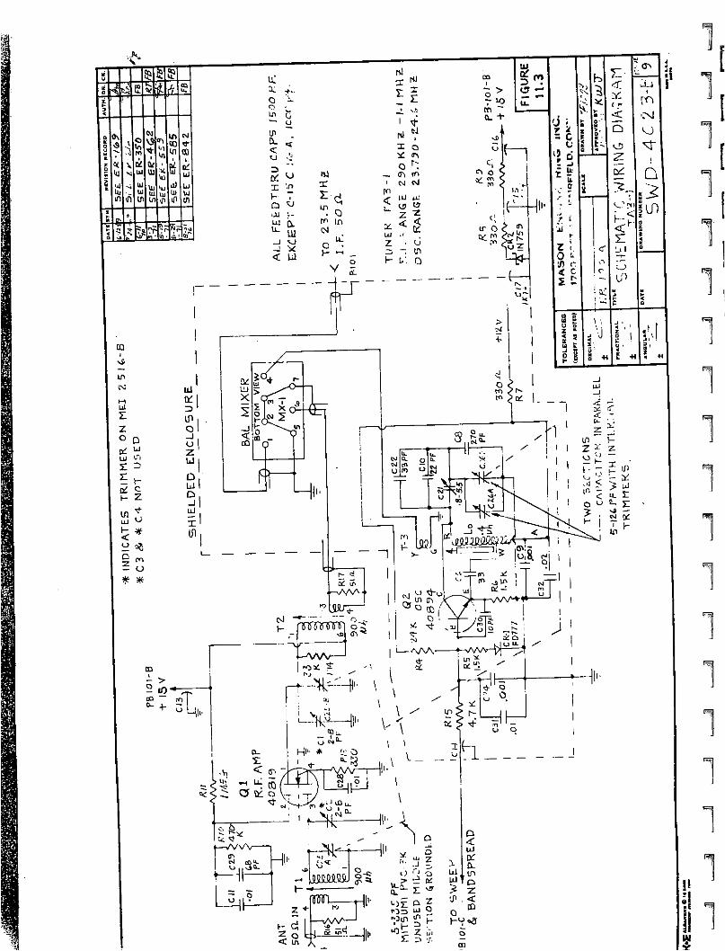
]
1
1
1(^

3Ki'l


j
B"1
pi
IP?
Lij


B
J
1
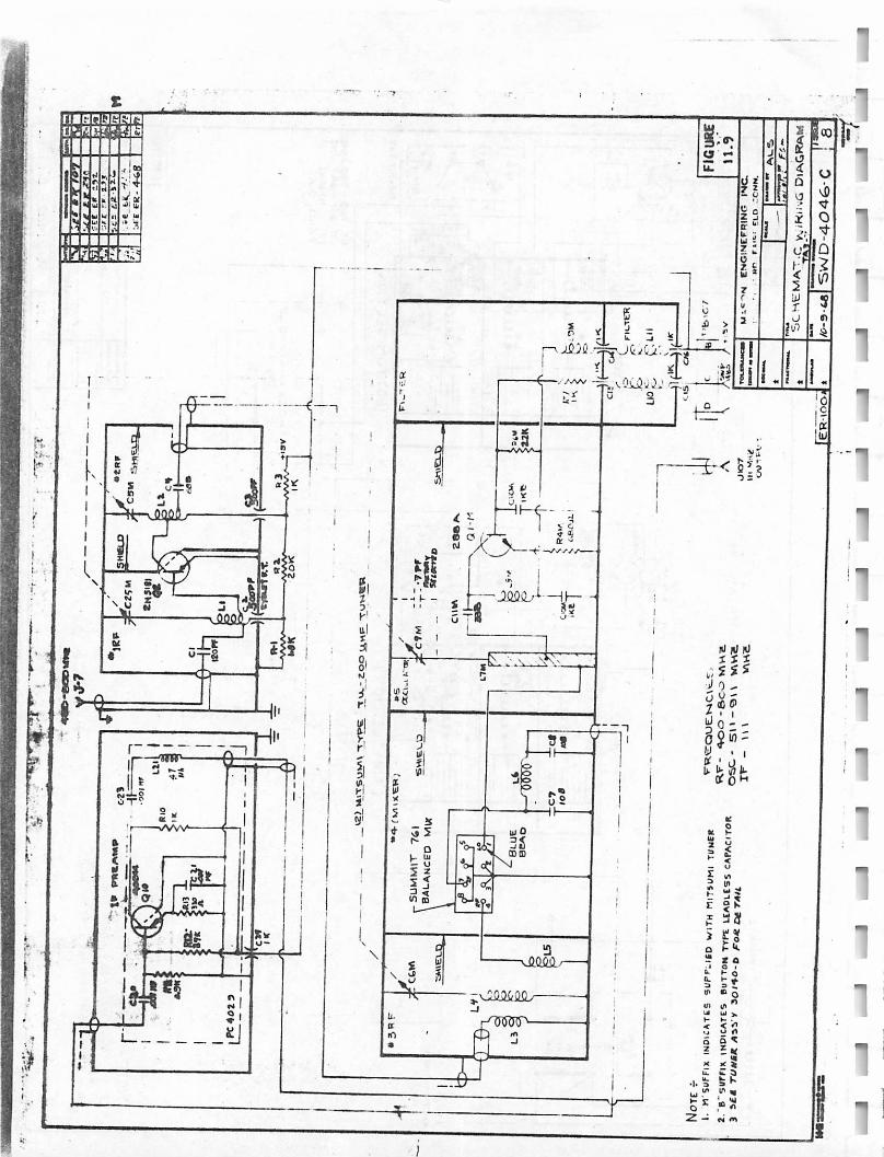

•J
J1
pi ,.■ ^PSI
-1
S i * " S t
.2flfl42fi

1
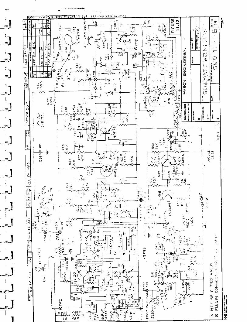
•■-■o'1-fr =? *34 b/.g«.tl l \ '9jV \iJL-va n3sii i-a-i
J
51r(J
J
J

£ i £ : l l l
r?~
JWRfkT r T l ' < A A A A * —
d* t feI as*I oKto
■\\>
j f d C o / '
■ L 'wHi~H
H H
-lAMV^ —<•
tv! • / H i i j _ J
(flfj
o>
$ 5 oAl Vi 0ua j. j<-» U 3
X 1■ Jv . .
FIGURE 11.13
Z 3£ '«
I:"
>•s
3it
a14
I,
'
•J- r ?L — * "- 0 - ■' ■>;J 4 . .1J * .1. *■u. i/) u -
3 v.•' -■ *
n B"- \n <C *
o 5
3S2 3 ■H
• I
;;C/:o;
f^E
- i , i
\
! ^ -i - 7AAAA—
§§* _ L _— I I - I
'3ff— AA—ii.«*-€-
.. i
#-+»'s i
L -14-
Hi-
Hi-
i ! I
1
n(5!j
° T« ' ' ' t. ■ \
HB>—
a £
>Jh •:...V.-.J
T i
» - / / / / y — <
i ; : . 1«,..
HI
) f' f t

rlt - r .O V
(^U- . 6X N

f N O O o o ^ n r >
° C< t* 5 5 5 -n-n
I I I I I I I— ^ 1 ~
u l i l l o 1 °C O tfl O 4» ot t i - t 3 3tn tn^ tn ai u>
s» — oi -j r n><r> T :., * * «»
ol l i - N Ol^ * * W
I P l " • " "
X i u
*(§)£)-n ti
n oS3isH<=
Hmo
rcm ^£ o> 5■* -oCD £^ £P»O 2T I ^TJ </>m £* 3 n£TI —'
C!*l00>;
I* » «• 3 * 8i
E3l °1 * 35 i ta
<($7 a(\> <7!nh H fT7 ':" ':',~s O *on P3
XX) 1 co <?n\
00 " 0 i 0s«n I 8
1■< '.
-n! .1 1*
IV ;(j i~
11
Hii''.
PIm
Ui£0
IT.
m
r
P1


J
J
JJ
_ ]
J
a!u £1? & X U i I
I D
UJ
vp |Vao
1~ tf # tt or »*■o —u. d z
aP«
i<
jV
Oc0uc
ON Gi Ul
J) GDxj- <
2§o§3
azJ<
■oM>0ct
o
odQ
1z0S
I IUUJl/>
i fUJ
U lUJl / l
ciU)
UJUJ
iuUJ
5>
03
UJUJ
0£u
UlUJin
1 -
ao
n2 9
O < aKUJ>
oi t
3 ?•1>m r \ ! T i r \
nUJ
J l '5 DP5 CO
<a^ =3 H r e ;r; >
,1
282 Ji
O o
>ft."2 Q<
5 > * H "T"
_. Q_ m.i i x 1 - •
S so u S J
3 z «< 3u E 3 e 2 ? u
oX
-j 323
uS 41
<e -hai -h
1- ^ d
D
<i
OO
f > * \ x ^ / « - • (\5 / * * O cv
^ V i?» UJ*3 \ / * " 0 J >/ * n o
f u(Tt r
^ o1 - ^ l i .
?>■
i n - -* U i i ' "
~ U J * * -
o II ^ ^ . < f e §/~X N h * >/ / \ \ — • J O
I V Y ai / > ^
, 1-uJDo
r f 00 I 4 ^U J 0 ^ L Lft!
5 CO I- ° \r
/<r>
1 o * j- ■»■»~.«1 o O 1 -
_ j:
^—w\_ * — v \ A A i A A A ™ A A A ~' V v v v—■— V v v—_ ^ _ £ t o Z - * - * a
3 £o
uJiu
Ul z 5 UJ •u Oi
H"*
5UJUJ0/
o- 1_ ll l J
z<Oi
QUJ
21
oJo
Hi-2 < < o >- o Q£ H d) u
>•
>• O k
+ 0
0o
-O "50 6^ r -
8Tc
§<;i
—<;?c
>
0o2
2
<
UJ
J0-_ j
PIVUJ
u l
o.
U J
DOou
D
y -
5)2UJHzCj
Q&
z111
J
LL.
UlOOn5
UJ
j<H2OM
o
UJhjft-J
zorJo2o
IV
q
Zu.
)\ 1 * * vff>
— o1
I «D «^ t K J
< u > > O \ 3 u X x
cr> 00 r- v 9 m -4- f O oJ - oz

pi" >rJ ;.
p i

f ^^ l
P3H

*w 1
1!
pr
Bl
J
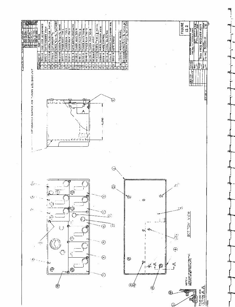
« f s e e s e s g
M S *
ism no r- to <*
•*?>
IM 3
C40£
O C4 u*3 d
ig
l\
Is
l\I f
ii i i
i ^ - ^ ,
GK
&■ ' -
& -
0".
'■i>-~-
I W k .
J
r

J

0 o0 0
oUJ
® -> Q- •■O 0 c
Cxj \<& © ©(g) ! ^
O O O O
LUQ
f*i?3
noLLOC\J
I 'LL!LuX
f^7|
ra
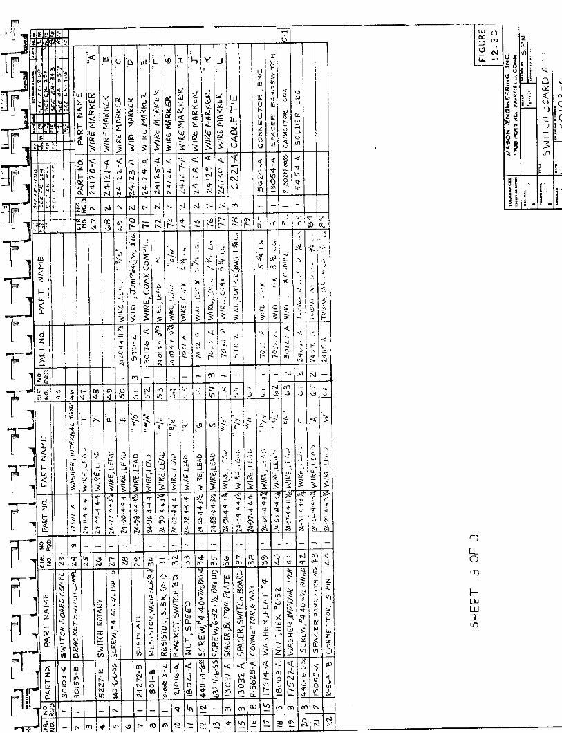
\ti O"
=5 m ft.2 CVJ H
<•a" 8 • I4 <«*
V3' s n V€ - cy Is> 2*-f o
x .r o1) 5$
w * t : IC• r- v j * •»
?8— *— X3
?. t
j r
a iu 5
1 £ c j 3 * E 44
LLO
LULUIE

1!!'?!^;v^!l;]Jj!jif!,1]j!Jn[iT'i--. \
ra
R
1R5
^r"1iEEf5MS?yr

•4*
JJjJ
■T - V
»r -r
855fr 51?$
M
,-J

«J>tBMl»llitfftll ll'lllll l •»■ >iH«IMl li i n — m i -
III »«ri | i
- M ;■ : h m - ? i ' 1 1 i t ' ' m ; ! , , « v1 • i j ! i , ' I \ i l i - n
11 11 ||: • ! i»|-|' || I J.) 1111 ' ■ i:; 11 j 11 f j it iI ' l l . . 1 • ' . 1 " ' . .
H+'
H l U U l U - | | ! . » x , l { i j r . h J f J r U f l i t t . | l ■ : . : ; , , •
II.J, JJ_ -J*< J~J [TTTTJ || Q _j (|; , , ; I ,, ,| I.: ;
M l - I. ( i . : .
I • u _ L M K ,I J - ^L_ . I l l U
I if
10
j li.
»i n13
ni:! * ; i '
^^&"^a it. J :.'---'.--mmm© 0 ©© 0<*
" ■ f f i f f l *
IIo <
f t•I- hO ' v O
¥
3 a
si Sa e
^*3n
• * ^ P M ill f f30ft ^^Pgj^M^ :.v;
01 Si

—rr\—h*
- ' - ! ( v j - _ ' _ i ^ - i _ - i o » i ( U | - | M | - t | - I -_ v , - , ^ : U . n f v l i n ' r f v O l

RS,
I S
J

jj Jr- jf
wj
L "";jf"j
■i » - — ^ "
z<z
a1*st fl<o«o4
1CD
au
nuV
>
t l
2<K
U
8
<o?*ohJ>
2<1-
aUl*J
i•53U3
s3erfUl>a
itulh|J
IS;i
i1
0
:*i tf■i
1 >'J 1! S
II' '5
r 4
fto
1«gu
<ui£9
II*
8lW04
■<N
*>,< ;5 !>8ao
f■i<ro3
I
5
S<a•<■i5
u£
5
i
m l
8o
(II¥ \t|£| ia a'iin o
<O
s
*
J1
jj3Sa I
111s j "I £ *oz1-K<a
o
•4
MQVI
<In
i n
<<■<
COoffS
U ?J8o l o
(iti f B
3■i §i'4 i i n
ia
<ip i - i O
31- f 4 _ _ * d <
Sj m i n ^ | r <o ff* t I A . t r c0 > | « t l « a Ft J r l N ^
3 u t r s t J 9 5» SlU ul u i - X -SA.LSU
« i o w
O c^
1*


J
J
i
t fl
IL a0oin
**
5 *£ I i
\| a .
00 ao
I3«
<JL-
-I tf QC <c ?2 * i i V0n0
i >Q .
v 97 D >o i ^ ' _-K l ~ 0 2
i • > -» ■i -as
I 3i uiUl
0£u l
UlUJifl
sl-
iuUJUl
>
Lj
i
X
Pf It <OLLi—1
<
llhor0
ua
oc0r*(P
.1)
10
i7)"J
a0
(0It)t0
if'J
0
v0h
•J
•N.
<3»v .
O
O4:a.<
4n Of)> c• • o H> W r " > - , o u f t a:- tc DC IX V <
IOO0
inOo
00
Si •.-«o .
*•*1
IQJ
Q1-
< ^ i o p
T
o1
<nJ
3oAc
c4
>-
N
Oa.>-f-oc
b90
1
I
\o i nCO W $ m «M .-i
rsic, o o o o K (M
n — lJ\ - ft) - i ■CVJ - - - - - — "- ~
i i - CVJ m <* in Vfl r* CD 6 i o - (V) (0 ^ *J?
jr a -i fOjc z ^ iDj —■i r u!u ff| a or; (X!ar. o—'—' - -j—*■ ■ — —■—'—'Mi M i
h uJ

fe
\
SSsIJLs
o
(OV\

mmIJcvi "r — o° Siinl%i%'^'^i^-0 £ * ♦
—l-t4-- )";"|- ihrtoiv9i^od)!9'-i,!?,?'t|!?,j?—^_ i I I i l i i ■

m?!
_ j
Iouair
- 0[j 179
Si
O i l I
U l - _t— i .
iZ <!
AJ|J3U jjX
> - lu±u<i < -
5!
5- l ( V ) ~
CVJ If)1 <t. ->!^
> ! 5
i tc' r
O &b i dj hu2 IKrJ | .-n)en i <o
Ql*lSi
Vj
»**,
at:s !'<
oo
CO Cn O:;!(0 «oI L
\)
■ \ » | ■ ■ ■_; ^ fi. o - & <r
**
* ! » o
~ ~ 3 —3 " >
x. - ^ u
^
Lbil
.. X
c c
U0
D(/)
•j!
DC(JIDt
u X
Z*Z0uD- lhiU.a<ut iat -m0a.co
2 c\)
8 fz ■ t \
ix2
UJ>oo2
II
*Ijl
DOI
00
foiro
U6CVJ
o
o
okU l
1 ^
r^
Rjj

too
UJ
ooi * t/>
o o£i - ox> H(0 IPZ in< z


J
eG*-J
CJ7 CJ
2 z- oU
5 aU) >LUl fc 3 *- w e r f M7 <
Z °
k k^^
<NJ
88
U u
Ion
I/)
o5 0
I
0)M
! 0loo
u \
■::L
0)S3i
O)CMi
■I
l \
QiooI
ft
0)1
<P 111! - - -u
/ « * * ^ j• o a -i 0/ <cr
Hv**.i. J> O
(-G Si
UJ >fi uJc / ) Z ^
St
3?31UJ

H
?' "• 5j S :/
u. """ -
I *
t J.
uTT
*%^B
* tS u X
0 Q H W
?«$1 «, Jo
.'<?.
4
1
IJ
r t i ' ^ j l

> 7 « $ * '
igapnu
tfj*fji5trt
w> \j!
Q!
gStegl
b 8It °M l
r :
f t4*i-
K s s ^ K, 1*1ss s S Q Q ^ ^ S C\ QiQ Q Cj to ^K \ ^ Q ^ ^* k ^ H. Ci <r Q * | * *
Q| tv K \9 \% ■<*i to * CO •>* -> 7 T •v «) Vr\£ v| >1 >J uu U U -4 £ U U
^ ( Q u Q Ui_ J
«*. v5 *j* * -J 5
] ^ts ( +• - ~ ~ - - T ^ T E ^ I . ^ -
o
m
L r
k i
o r '
i — = -
U aJ
* i
vo-
'I
i c,
M ! - i i _ i_. _ layI i . I ' l l L J ' : T 4 ^ " - - i i r
i/?'i J.lli^,rVjj^!k^-^t^ ^ * . \ \ ■ _ J ; i _ 3 J _ i i _ D s i > l i < *£
\J.™-\\ I :E3SI I a L / , . , - —
Q i / i • - (=>
* -<r
®k
ie=-
- ij -
K
U" \\\ \ \
w> \ >
r ' w ,
■/>
^c?|8fe&
§
S -^'ec,)
r *<fi)
O j i J
T--II I m
A . \ I n
•* i
O A O
I I I
i1a) w
tii
(D
<■ j2 "• w >
In id ' |C , i * i
•" UlvJ Jul> > S '-< "(
i H ^ i O i i ' s s i.i-».—
^oO (p|2 -
^ r>
j - r
«0 (O <* Wv9 (0

-m»;j&, . .^ r^ i^u i i^ l^&fV^S^t i^ f^^^^ . - i ^B f c i&EB&&b i ; . (5


r
JR.
f
1]
B U I | J
FV-J
rjafl-CZo- t r -nM^ LOIS

13
J
1

f<$)
Fl
1 3
1
J
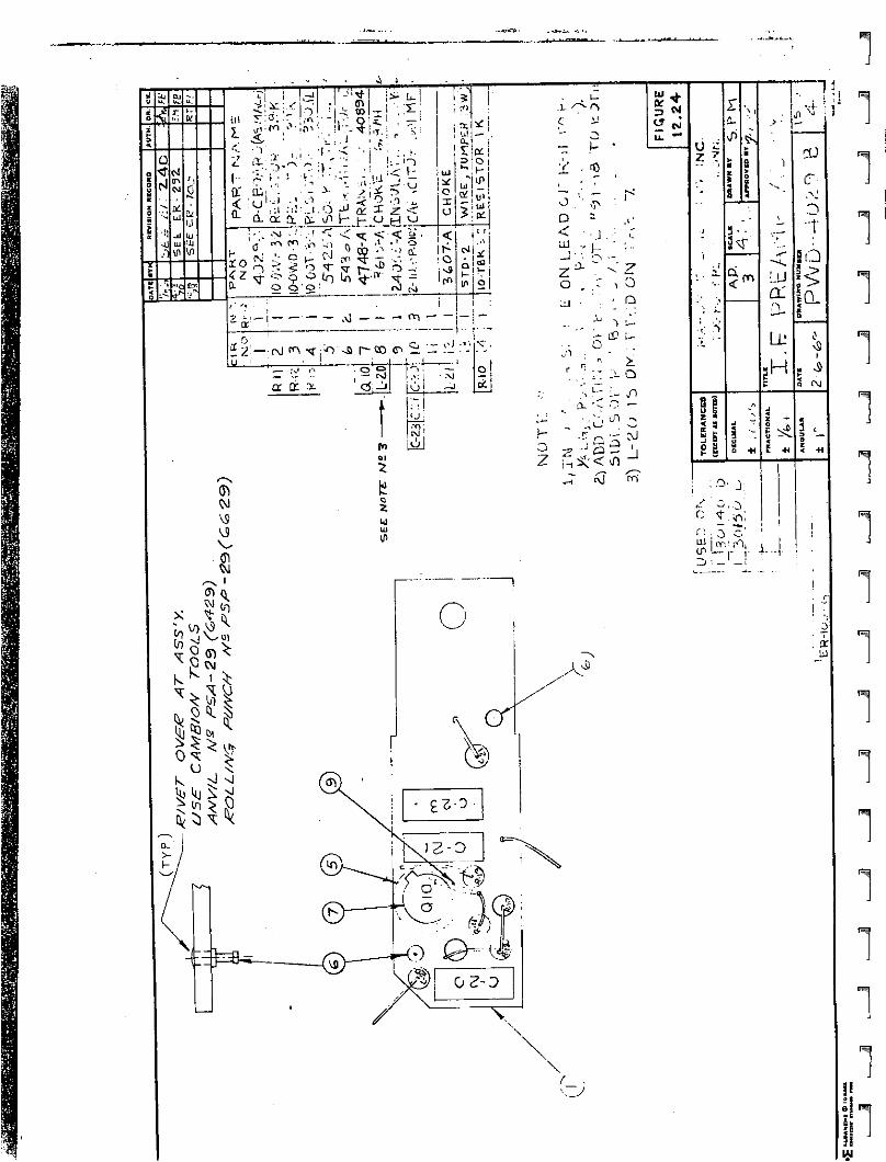
IS in
■ v
a:'on
b?vv.;
- ; ^ i
3 £! "--
T
^•o S"
or< ;Q. .1
I X
<za
^ i * ^ * ••' '. <° -^ ■*-■ O .^ a I 2 <vP h- \- u h aj^< < * r < < S i i■ » - • o
Q l, t
^ ? 3"*" v r- ^rO oi
* !
2 °'•—»11— •
J * !C i u i
r
oil
u> I o
i'o'sft r-cc <^ ii ~ ._ :I .K I ' --M
C ' 1 2— ^
fi t : *3 «C7 <N
o
< " J
- I ' ^
o , -c
5 : ^
< z
.1- O:- />
7. Z
• i - ^
z »
S i
s8
2T
c6
m :JJOL,•■>
Lf. H
SO
IQ-
i
s c\l
5 ^<
" O j O ot fl L - j .D i — —!
4-4
UJ
f*^
p ^
i "mj
r$
i^ i
1I1e| Ri■ eit141

i r P ?
■ I
S.3
§£s^is
i t i
n

1
J
1

c , ? 0
<C in
•» i fc:? • = t .. f t ( f t CO Ji f , . - - 93
r o -
< ~u ., -Ir* ._ o « r
* 8t> \T 51 Zlle i
Sell;$ c.vi
• D _ r . ^ - u o . f v ■ * • 5 S i ' S * ! S 6 3 5 . ?£ t o C o f e 5 o o D j 5 ; * , £ * 3 : * f r f S J g i S
a • • " * t - » - i • " o - S ~ A * a * S ' • - « > o o i ' . ? e < N . > j u o o 5 - J o m ' t r i S B p j 5 ! « S i - ~ ( 2< * . ■ I £ - !■■ - N S . . S i ' = S - > " < * 7 • ? : ' A 8 l : t - o < > S S o o u > » n « » « , J J r - £ f . J > - £ g J 3 8 E 2 S
. v j > - - -. r «~- _- M « l - . ■ — -' - 50 • - - .1 . -,- M - - VI
• .'.«. T' C 1 ' v n t •o • cr. Jl ' ~ / ;• •• Cf t ! \ M
/; . ■j . * :n,<s > * •' T .1
.".& ' •t St ? '. = ::.: a?. •c3 - v l
tt X . 't- - l'. IPM .1
txjS3 § mccjt ar
M -*• . i c * C V ' S fci"; " ■ C ■ K i f i : 5 .*.!*. .3. : I JX_' ' to i ^
. i n — . > . i 0 — v ■ • i f w > * * > • . C T ' , r ^ a c n :+ T*t - - • • - •. «i j).-..lftwi. . -n^Y | -J**|>fliaim ■« . _ - - <■ - i - • -■ • - . . w : I » £ 1 3
e: d j j - - on". • 5.<5;/'.9 ^^•i .«, tas:* • • - - — i ^ «. v i V - ^ £ : » |
O CM
I*0w—Si-
O L
SI8e32

!*>».««•?»
*» <t
t v i• « :
H- i ' f j - - N " N
rf - w •/> ♦ ai J r*
in!J.S*!
" * e l J e j
e$0 0 U
CD
Vit l *
M tj CM
«?
<l I a), lo • Q U-
• I ■ , , . ,
\°^5—>£///. 'o i l \ M i j r J t \ r -
\ ' ^ _ ^ * m H t j j / \ y ; o
O

L . I _

'M
I 615 s
In
V0
1
4-
l/>
CD00
v5
-\r
$ S i
cL if>
$
iCO
a
cv
^
o o/ O
W *
£
cfi
S|9
■oo
lT| s i S t t
0/
^ « | ^ V4*
^
in Jin
<U
£
COto
^
M
,\i
O
TO
<
u> CDa: <<*15 Na—oiLL
f -UJLdnr
uo
UJUl_x(p
', ttt


aarSii-4'l'Tfersi.- . -^ tSff rW- iaa i iv
,1 bl lei Is! I I!Esas&ssras«i
Bgii lSlSl
m3T
elk/
1Siic
8
Ito(41
si 3
cr'Qi
35rvJjNM i . v
M.-i-T|lO si)tM ifuI'M
^ J .
SI-. ou3 dSB
z ou
... a
II
n
iN
4u
1
if
IS
c

& ft■3 * /


WSi- h i C
Mim8r- a
l«
U
IT
l i l S
lJ _JS

r


jS
l i
1
1


nisIhm
iVIHj
S5i
8it
to
53s
. J *
3> I W^'fl VJN o j O ^ ^ c n * < n
l *
J?l!> ?>?(JiMCMt^WCMMCM
I*
S tO CM <l
1?
J; in
QI
0I*

O CM
]'*
|M<
|iu
fir

J
Hi
u s
fc2*
UJ
E5?
I
oi «o <j m s9
•f CQ
ri / ^ O
< ~ i
in
cTfT
IGURE 12.43 » *s0
>in
-JCslirt
u. HB dz 3
K11
INi 0
S3 |S 0v9
U 5 IS^ (A Q
£ im•i^ £
i -u>
1 ! * r2 *"
ii 2 I5t «
<5.
in

n
HI
1
1 7 ^ 1
l^ f j

OS,« wC O t ^ ,
3 wK 2W HD J05 OH >
(,'▶o .
< N / W ^ hH
«W H
» 1!S £S g os g sco o Q5s W ^CQ co <
W . £* fc sd z ;h < a
rI""11 S« iI Q S .I w
5
M lCD<
k
«o * jH 3a< ■<-»
▶J p5< W
3 .cz zo £ oco C m
KWW
oo i JoCO >
W ■J COW 2
g Q ccc-* o•J 2 Wo D>
X
COQ H< Z oa. w CM mo 2 C n P« Q
HZW
5X
wKCO
2 <W CQ O
Z< W PQ
H < Q Q X H Q< W O . Cij o ^u, ■S 2 2 CM H 2 CMoOfw w
• JCO<u
ss
>•W•Jw
w2oCJ
▶JwQO2
11500 A CABLE ASS
iawp.■>H
CQ<
QrHCM
«PC •J
wQ CO CQ w < ^O2
r-i CO CM 0 0 CM f-Hm o 00 o f-H COto CO t o CO 00
CO4-*
COK d
0)
<u Oh (X CU (X CU2 X X u
3x X X
KWZw
uo
COcda;2 N
o•J<z
z<K X o ■S3
2
^ X
^ oo o
* s o o ccc P- m OJ <^-<»—•CO CO s > 1
1 1
o oCxi] 1 o o m of - C M . T*< r f OS
F»
! !
IAI

1 *,....
1 u1 K
—1 08 x■ *•R 9N *
0K0oHK
s• Kii WtX c -
21 •>• CO• rMH«0

CO
j
i
0enw
n &i — i ^ *CO U< wCQ (X
XWZ<=>H
zoHUW
—6W
xc< a
*"3 K •CM3< W oz z
S w Oco O l O
COwX
S 5X •""•H oU Z
£ "z w2 fex cw ^" 9»-< x
-> z5 o$ -1Z Ed^ . -Q w ^W H 2— . i — i • " '
WXO
WwCO
w o
o 2uwx
HzwiwQWQZw22OuwXXfciX
OXO
! !• si .
<a•J1

Xo
CO
CO2
O—AAAr
^
o c . 20 C o
o 2«WHW> 2
i n E-CM i-3i U C° o >

t
I.
l iXOHX▶J
< wz * - T
9 ?i wCO o =*

Ifif
1
1
1;1

s^f*
BY DATE S/N12/74A3 DATA SHEET 14-A
- AM SENSITIVITY 10 DBS+N
FM QUIETING \20 DB DIALS*
8 . 1 N 8.2 8.1
i IF REQ AM MEAS. I F REQ FM MEAS. jysQ MEAS.
\ TUNER RFMHz BW SENS SENS. BW • SENS SENS —1 KHz UV UV KHz UV U V KHzJi
.002 .2 1 . 5 / j M 1/8"1
T 03 .100 2 1.5 2 3 1.5
.300 2 1.5 2 3 4.5
. 3 20 1.5 20 5 4.5
T 1 . 6 20 1.5 20 5 9
1.0 20 1.5 20 5 15
1.0 20 1.5 20 5 *
T 2 2.0 20 1.5 20 5 .03
3.5- 20 1.5 20 5 . 05
3.5 20 1.5 20 5 .05
T 3 8.0 20 1.5 ' 20 5 .12
12.0 20 1.5 20 5 .18
12 20 1.5 90 7 • .18
T 4 20 20 1.5 90 7 1 . 3
43 20 1.5 90 7 . 6
43 20 1.5 90 7; 6 ,
T 5 80 20 1.5 90 7 1.2
130 20 1.5 90 7 1.9
130 20 2 90 7 1.9
T 6A 160 20 2 90 7 2.4230 20 2 . 90 7 3 .4
230 20 2 90 7 3.4
T 6B 300 20 2 90 7 4.5
420 20 2.5 90 7 6.3
420 90 2.5 90 10 6.3
T 7 600 90 2.5 90 10 9.0800 90 2.5 90 10 12.0
800 90 3.5 90 15 12
T 8 1200 90 3.5 90 15 181600 90 3.5 90 15 24
■ 1 ^1..EXT 111 J JOi 1.0
W positioP ^ ^ .
* «*• 1 /« innh H-inl Hisnlianement. Tl dial me'asured un 2 KHz B n

BY DATE S/N10/77
A3 DATA SHEET 14-B
8.3
1
TUNER 03 1 21
3 4 5 6A 6B 7 8
RF MHz .100 .6 2 8 20 80 160 300 600 1200MIN. BSREQ. KHz NA 1.2 4 16 40 160 320 600 120 240
BS NASPUR. REJ.REQ. DB 50 80 80 80 50 50 40 40 40 40
IF FREQ. 455 23.5 23.5 23.5 111 23.5 111 111 111 111
IF REJ.IMAGEFREQ. ..01 47.6 49 55 242 127 382 522 822 1422IMAGEREJ.
TestFM Dev,
Seti
RF INLevelIN
AudioOut
FMOUTPUT
20 KHz BW FM NAH 4 KHz 10 MHz T-3 10 uv .3 v90 KHz BW FM NAR 20 KHz 23.5 Wide Bl 1 mu 1.0 v" V5"v"~
1.6"v90 KHz BW FM WIDE 20KHz_ 23.5 Wide Bl 1 mu1 MHz BW FM WIDE 65 KHz 23.5 Wide Bl lmu
8.5
8.6
8.7 IF BANDWIDTHLFR .2 KHz IF, 60 KHz RF, between 180 and 250 HzLFR 2 KHz IF, 60 KHz RF, between 1. 8 and 3.5 KHzLFR 10 KHz IF, 60 KHz RF, between 9 and 13 KHzHFR, 2 KHz, 600 KHz RF, between 1.8 and 3.5 KHzHFR, 20 KHz, 600 KHz RF, between 18 and 24 KHzHFR, 90 KHz, IF output wide jack, between 70 and 120 KHzHFR, 1 MHz, IF output wide jack, between 1 and 2 MHz
8. 8 SWEEP WIDTH PANADAPTER MODE
SWEEP WIDTHPOSITION
S W E E P W I D T H T E S TRF TEST
FREQ.SWEEP WIDTH
LIMITSSWEEPWIDTH
C E N T E R I N G T E S TRF TEST
BWFREQ. CENTERED 1500 KHz/Div. 50 MHz 450 - 550 KHz/Div. 50 MHz 2 KHz
120 KHz/Div. 50 MHz 100 - 140 KHz/Div. 50 MHz 2 KHz*w
30 KHz/Div.
6 KHz/Div.
1 KHz/Div.
. 3 KHz/Div.
50 MHz
600 KHz
600 KHz
600 KHz
25 - 35 KHz/Div.
5 - 7 K H z / D i v .
.5- 1.5 KHz/Div.
. 2 - . 5 KHz/Div.
50 MHz
50 MHz
50 MHz
50 MHz
2 KHz
2 KHz
2 KHz
2 KHz

12/74A3 DATA SHEET 14-C
8.8 (Cont.) SWEEP WIDTH T-03 MODE
25 Kc/Div. 100 KHz 20-30 KHz 100 KHz 2 KHz
6.5 Kc/Div. 100 KHz 5.0- 7.5 KHz 100 Krfz 2 KHz
2 Kc/Div. 100 KHz 1.0- 2.5 KHz 100 KHz 2 KHz
. 350 Kc/Div. 100 KHz 250 - 450 Hz 100 KHz .2 KHz
. 090 Kc/Div. 100 KHz '50 - 100Hz 100 KHz .2 KHz
SWEEP RATEPOSITION
1.5/6 us
6/30 us
30/135 us
135/700 us
. 7 / 4 m s
4 / 2 0 m s
8.9 SWEEP RATEFREQUENCY
REQUIREMENTS6 6 . 6 1 6 . 6 K H z
1 6 . 6 3 . 3 K H z
3.3
740
143
25
.74 KHz
143 Hz
25 Hz
5 H z
FREQUENCY
20/100 ms 1 H z

BY DATE S/N
CHECK LIST
11/76A3 DATA SHEET 14-D
8.1011121314151617181920
222324252627282930313233
ITEMS3S3S3S3S3S3S3S3S3S3S3XFH"LFRLFRLFRLFRLFRLFRHFRHFRHFRHFRHFRHFR
34 BP-7
VERT SENS (1 MV/DIV)SIG GAIN CONTROL (50 dB)SIGBW(1 Hz-1.8 MHz)Z AXIS SENS (40 V PP)BRIGHTNESS CONTROLFOCUS CONTROLSWP. CENTERING CONTROLSIG. CENTERING CONTROLSYNC CONTROLEXT SYNC INPUT JACKS W P G A I N C O N T R O L ,■H I - L O W M E T J i J k y W L T O l l ~ " "IF GAIN CONTROLAGC TEST JACK(+4.2/5.2 V. No Sig^-3.0V at . IV sig)DET OUT JACKAUDIO OUTPUT (2.5 V out/ 5 uv in)IF OUT JACKB F O . __-HI-LOW METER SWITCHIF GAIN CONTROLAGC TEST JACK(+4.2/5.2V No sig, > +3.0V at . IV sig)DET. OUT. AND SWP JACKAUDIO OUT (2.5 V out/ 5 uv in)BFOONE & TWO OPERATE
35 ACCESSORY CHECK OUT
Q u a n t i t y I t e mEarphone with cordWhip AntennaBow Tie Antenna with extendersFerrite Rod Antenna #1 (2-300 KHz)Ferrite Rod Antenna #2 (. 3-30 MHz)Long Wire AntennaBlocking Capacitor20 dB Attenuator PadBNC Male/Male adapterBNC Female/Female adapterEuropean Power plug adapter #1European Power plug adapter #2Five foot BNC cableOne foot BNC cablePower Cable2 to 3 wire ac adapter
Quantity ItemRemote Tuner CableManualTool, common screwdriverTool, Phillips ScrewdriverAllen wrenchSpline KeyAttache CaseAttache Case insert #1 LowerAttache Case insert #2 Lid, largeAttache Case insert #3 Lid, smallAttache Case insert #4 (S3 Pads)Interconnecting harnessSpinner knobAntenna Mast