mas (mdp arm simulator) rolecks - university of cambridge · pdf filemas (mdp arm simulator)...
TRANSCRIPT
MAS (MDP ARM Simulator) Rolecks
Nicholas Caldwell, Paul Fidler, Peter Long, Geoff MartinCambridge University Engineering Department
Trumpington St.,Cambridge CB2 1PZ
29th August 2007
The MDP ARM Simulator (MAS Rolecks) has been developed by the MDP teamat Cambridge University as an educational tool to support an introductory coursein microprocessors. The package is written in Java and offers a simple IDE thatallows the editing of ARM assembler and monitoring of the assembled code underemulation. A simulated hardware interface (inc. LEDs, switches, analogue ip) isalso available that allows the user to interact directly with the code. When required,the developed code can be simply loaded onto the MDP Microcontroller whichallows the user to work at full speed and with real hardware and interfaces.
The software is based on the Rolecks program developed by Trek Palmer and TimRichards at the University of Massachusetts
(http://www.cs.umass.edu/t̃rekp/cs201/rolecks.jar)
1
Contents
1 Introduction 6
2 Getting Started 6
2.1 Linux/ (MDP EDaL system) . . . . . . . . . . . . . . . . . . . . . . . . . 6
2.2 Web . . . . . . . . . . . . . . . . . . . . . . . . . . . . . . . . . . . . . . 6
2.3 MACX . . . . . . . . . . . . . . . . . . . . . . . . . . . . . . . . . . . . . 6
2.4 Windows 98/XP/Vista . . . . . . . . . . . . . . . . . . . . . . . . . . . . 6
3 User Interface 6
3.1 Main Window . . . . . . . . . . . . . . . . . . . . . . . . . . . . . . . . . 7
3.1.1 Title bar & Top Menu . . . . . . . . . . . . . . . . . . . . . . . . 7
3.1.2 Editor/Source Pane . . . . . . . . . . . . . . . . . . . . . . . . . 10
3.1.3 Binary Pane . . . . . . . . . . . . . . . . . . . . . . . . . . . . . . 11
3.1.4 Register Pane . . . . . . . . . . . . . . . . . . . . . . . . . . . . 13
3.1.5 Text Entry Pane . . . . . . . . . . . . . . . . . . . . . . . . . . . 14
3.2 Memory Map . . . . . . . . . . . . . . . . . . . . . . . . . . . . . . . . . 14
3.3 Hardware Simulation . . . . . . . . . . . . . . . . . . . . . . . . . . . . 15
4 Simple Programs 16
4.1 ‘Anatomy’ of a Program . . . . . . . . . . . . . . . . . . . . . . . . . . . 16
4.2 Simple Arithmetic . . . . . . . . . . . . . . . . . . . . . . . . . . . . . . . 17
4.3 Assembling and Running Code . . . . . . . . . . . . . . . . . . . . . . . 18
4.3.1 Writing New Source Files . . . . . . . . . . . . . . . . . . . . . . 18
4.3.2 Loading Existing Source Files . . . . . . . . . . . . . . . . . . . . 18
4.3.3 Saving Source Files . . . . . . . . . . . . . . . . . . . . . . . . . 18
4.3.4 One-Click Assembly . . . . . . . . . . . . . . . . . . . . . . . . . 18
4.3.5 Two-Click Assembly . . . . . . . . . . . . . . . . . . . . . . . . . 19
4.3.6 Running the Program . . . . . . . . . . . . . . . . . . . . . . . . 19
4.4 Interaction Simulated Hardware . . . . . . . . . . . . . . . . . . . . . . . 21
4.4.1 Switches . . . . . . . . . . . . . . . . . . . . . . . . . . . . . . . 21
4.4.2 Sliders . . . . . . . . . . . . . . . . . . . . . . . . . . . . . . . . . 22
4.4.3 LEDs . . . . . . . . . . . . . . . . . . . . . . . . . . . . . . . . . 23
2 MDP ARM Simulator
4.5 Textual I/O . . . . . . . . . . . . . . . . . . . . . . . . . . . . . . . . . . . 24
4.5.1 Text Input . . . . . . . . . . . . . . . . . . . . . . . . . . . . . . . 24
4.5.2 Text Output . . . . . . . . . . . . . . . . . . . . . . . . . . . . . . 24
4.6 Use of Memory Map . . . . . . . . . . . . . . . . . . . . . . . . . . . . . 24
4.7 Modification of Registers . . . . . . . . . . . . . . . . . . . . . . . . . . . 24
5 Simplified ARM Assembler 25
5.1 Instruction Syntax . . . . . . . . . . . . . . . . . . . . . . . . . . . . . . 25
5.2 Instruction Types . . . . . . . . . . . . . . . . . . . . . . . . . . . . . . . 26
6 MAS Rolecks Assembler Functions 27
6.1 System operations . . . . . . . . . . . . . . . . . . . . . . . . . . . . . . 27
6.1.1 SYS Exit . . . . . . . . . . . . . . . . . . . . . . . . . . . . . . . 27
6.1.2 SYS ReadC . . . . . . . . . . . . . . . . . . . . . . . . . . . . . 27
6.1.3 SYS WriteC . . . . . . . . . . . . . . . . . . . . . . . . . . . . . 27
6.2 Hardware i/o Routines . . . . . . . . . . . . . . . . . . . . . . . . . . . . 28
6.2.1 MAS LED OnOff . . . . . . . . . . . . . . . . . . . . . . . . . . . 28
6.2.2 MAS Slider Read . . . . . . . . . . . . . . . . . . . . . . . . . . 28
6.2.3 MAS Switch Read . . . . . . . . . . . . . . . . . . . . . . . . . 28
A ARM Assembler Opcodes 29
A.1 Data Operations - Arithmetic . . . . . . . . . . . . . . . . . . . . . . . . 29
A.1.1 ADD ADD . . . . . . . . . . . . . . . . . . . . . 29
A.1.2 ADC ADD with Carry . . . . . . . . . . . . . . . 29
A.1.3 CMP Compare . . . . . . . . . . . . . . . . . . . 30
A.1.4 CMN Compare Negative . . . . . . . . . . . . . 30
A.1.5 SUB Subtract . . . . . . . . . . . . . . . . . . . 31
A.1.6 SBC Subtract with Carry . . . . . . . . . . . . . 32
A.1.7 RSB Reverse Subtract . . . . . . . . . . . . . . 32
A.1.8 RSC Reverse Subtract with Carry . . . . . . . . 33
A.2 Data Operations - Logical . . . . . . . . . . . . . . . . . . . . . . . . . . 33
A.2.1 AND Logical AND . . . . . . . . . . . . . . . . . 33
A.2.2 BIC Bitwise Clear . . . . . . . . . . . . . . . . . 34
MDP ARM Simulator 3
A.2.3 EOR Logical Exclusive OR . . . . . . . . . . . . 35
A.2.4 MOV Move Value . . . . . . . . . . . . . . . . . 35
A.2.5 MVN Move Negative . . . . . . . . . . . . . . . 36
A.2.6 ORR Logical OR . . . . . . . . . . . . . . . . . 36
A.2.7 TEQ Test Equivalence . . . . . . . . . . . . . . 37
A.2.8 TST Test Bits . . . . . . . . . . . . . . . . . . . 37
A.3 Load and Store . . . . . . . . . . . . . . . . . . . . . . . . . . . . . . . . 37
A.3.1 LDR Load Register . . . . . . . . . . . . . . . . 37
A.3.2 LDRB Load Register Byte . . . . . . . . . . . . 38
A.3.3 STR Store Register . . . . . . . . . . . . . . . . 39
A.3.4 STRB Store Register Byte . . . . . . . . . . . . 40
A.4 Branch . . . . . . . . . . . . . . . . . . . . . . . . . . . . . . . . . . . . . 40
A.4.1 B Branch . . . . . . . . . . . . . . . . . . . 40
A.5 Multiple Load and Store . . . . . . . . . . . . . . . . . . . . . . . . . . . 41
A.6 Software Interrupts . . . . . . . . . . . . . . . . . . . . . . . . . . . . . . 41
A.7 Condition Codes . . . . . . . . . . . . . . . . . . . . . . . . . . . . . . . 42
B MAS Rolecks Assembler Subroutines 43
B.1 System Subroutines . . . . . . . . . . . . . . . . . . . . . . . . . . . . . 43
B.1.1 SYS Exit . . . . . . . . . . . . . . . . . . . . . . . . . . . . . . . 43
B.1.2 SYS Clock . . . . . . . . . . . . . . . . . . . . . . . . . . . . . . 43
B.1.3 SYS Close . . . . . . . . . . . . . . . . . . . . . . . . . . . . . . 43
B.1.4 SYS Open . . . . . . . . . . . . . . . . . . . . . . . . . . . . . . 44
B.1.5 SYS Read . . . . . . . . . . . . . . . . . . . . . . . . . . . . . . 44
B.1.6 SYS ReadC . . . . . . . . . . . . . . . . . . . . . . . . . . . . . 44
B.1.7 SYS WriteC . . . . . . . . . . . . . . . . . . . . . . . . . . . . . 44
B.1.8 SYS Write0 . . . . . . . . . . . . . . . . . . . . . . . . . . . . . 44
B.1.9 SYS Write . . . . . . . . . . . . . . . . . . . . . . . . . . . . . . 45
B.1.10 SYS SysCall . . . . . . . . . . . . . . . . . . . . . . . . . . . . . 45
B.2 High-level Hardware Routines . . . . . . . . . . . . . . . . . . . . . . . . 45
B.2.1 MAS LED OnOff . . . . . . . . . . . . . . . . . . . . . . . . . . . 45
B.2.2 MAS LED Flash . . . . . . . . . . . . . . . . . . . . . . . . . . . 46
4 MDP ARM Simulator

B.2.3 MAS Motor . . . . . . . . . . . . . . . . . . . . . . . . . . . . . . 46
B.2.4 MAS IR Read . . . . . . . . . . . . . . . . . . . . . . . . . . . . 46
B.2.5 MAS Slider Read . . . . . . . . . . . . . . . . . . . . . . . . . . 47
B.2.6 MAS Switch Read . . . . . . . . . . . . . . . . . . . . . . . . . 47
B.3 Mid Level Routines . . . . . . . . . . . . . . . . . . . . . . . . . . . . . . 47
B.3.1 PCF8574 Read . . . . . . . . . . . . . . . . . . . . . . . . . . . 47
B.3.2 PCF8574 Write . . . . . . . . . . . . . . . . . . . . . . . . . . . 47
B.3.3 PCF8591 Configure . . . . . . . . . . . . . . . . . . . . . . . . . 48
B.3.4 PCF8591 ReadADC . . . . . . . . . . . . . . . . . . . . . . . . . 48
B.3.5 PCF8591 WriteDAC . . . . . . . . . . . . . . . . . . . . . . . . . 48
B.3.6 PIC ReadADC . . . . . . . . . . . . . . . . . . . . . . . . . . . . 48
B.3.7 PIC WriteMotor . . . . . . . . . . . . . . . . . . . . . . . . . . . 48
B.4 ASCII Character Codes . . . . . . . . . . . . . . . . . . . . . . . . . . . 49
MDP ARM Simulator 5
1 Introduction
What is being simulated, image of micro/memory map?
Which processors are being covered (26 or 32 bit ARMProce3ssors)
limitations
Information about hardware (MDP Microcontroller)
2 Getting Started
Where and how to obtain a copy of the java code, web ad-dresses etc.
2.1 Linux/ (MDP EDaL system)
from menu items, from command line
java -jar mas-rolecks.jar
2.2 Web
Need to look at java start, ...
2.3 MACX
?
2.4 Windows 98/XP/Vista
java -jar mas-rolecks.jar
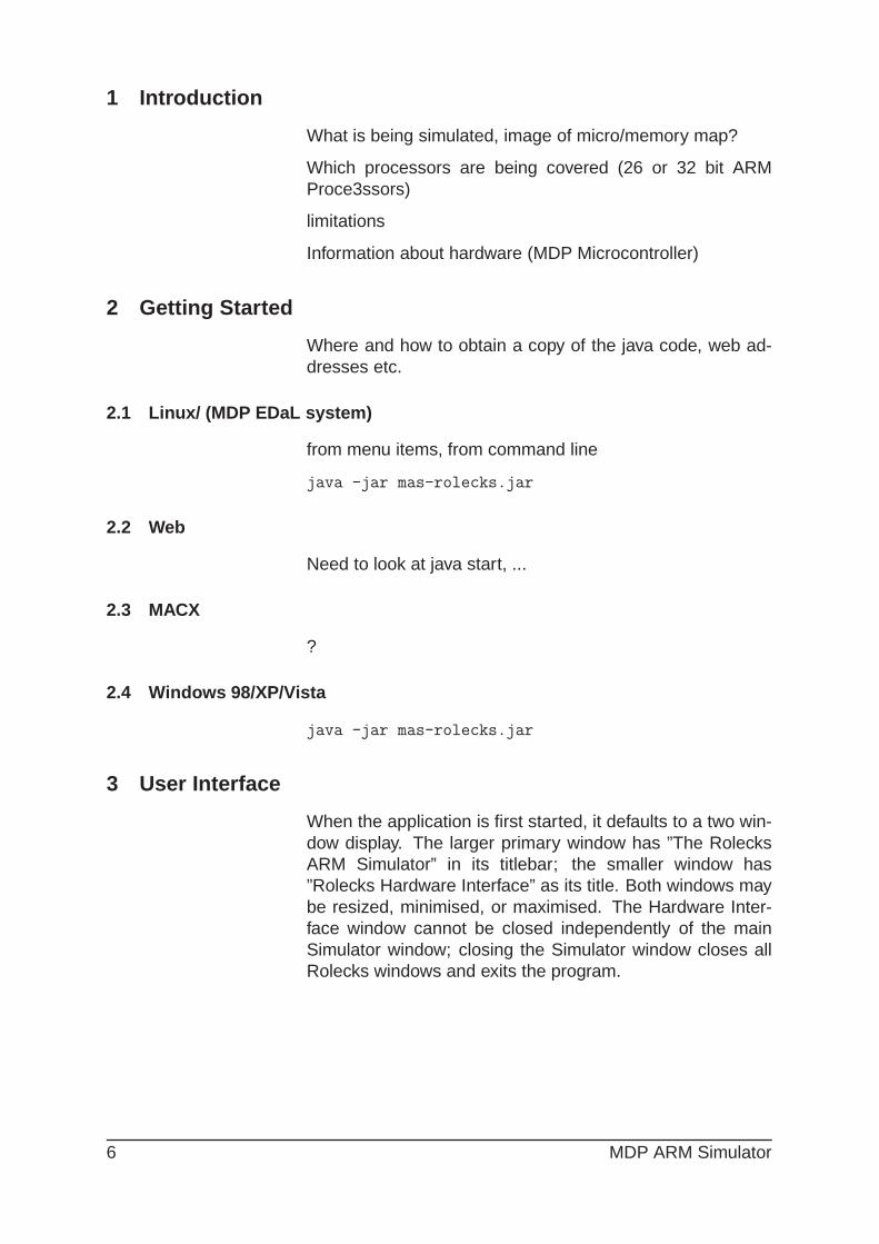
3 User Interface
When the application is first started, it defaults to a two win-dow display. The larger primary window has ”The RolecksARM Simulator” in its titlebar; the smaller window has”Rolecks Hardware Interface” as its title. Both windows maybe resized, minimised, or maximised. The Hardware Inter-face window cannot be closed independently of the mainSimulator window; closing the Simulator window closes allRolecks windows and exits the program.
6 MDP ARM Simulator

3.1 Main Window
Figure 1: MAS-Rolecks main desktop window
The main window is split into five main areas shown in fig-ure 1. The functionality associated with each area is de-scribed in sections 3.1.1 - 3.1.5.
3.1.1 Title bar & Top Menu
The title bar has the nameof the programe and the file-names of the source and bi-nary files currently loaded inthe editor and binary panes.
The top menu bar has six pull-down menus: File, Edit,Search, View, Build and Help.
The File menu has the following items:
• New Source - clears the current editor window. Warn-ing: This does not prompt the user to save the currentfile, so selecting this option will delete any unsavedwork.
• Load Source - opens a standard file browser windowand prompts the user to open a source file, which willbe displayed in the editor pane. N.B. source files havea suffix .s, e.g. example1.s. Warning: This does notprompt the user to save the current file (if any), so se-lecting this option will delete any unsaved work.
• Save Source - opens a standard file browser windowand prompts the user for a filename to save the textcurrently in the editor pane.
• Load Binary - opens a standard file browser windowand prompts the user to open a binary (assembled)file, which will be displayed in the Binary pane. N.B.binary files have a suffix .bin, e.g. example1.bin.
MDP ARM Simulator 7

• Print Source - not currently available. Future develop-ment.
• Print Binary - not currently available. Future develop-ment.
• Quit - this exits the entire simulator. Warning: Thisdoes not prompt the user to save the current file, soselecting this option will delete any unsaved work.
The Edit menu has the following items:
• Undo - this is a standard Undo facility which can beused to reverse changes to text in the Editor/Sourcepane (see below) one keystroke at a time.
• Redo - this is a standard Redo facility which can re-store changes that have been reversed by the Undocommand, again one keystroke at a time.
• Cut - not currently available from menu.
• Copy - not currently available from menu.
• Paste - not currently available from menu.
• Select All - not currently available from menu.
• Preferences - not currently available. Future develop-ment.
The Search menu has the following items - all currently un-available:
• Find
• Find Next
• Find Previous
• Replace
• Goto Line
8 MDP ARM Simulator
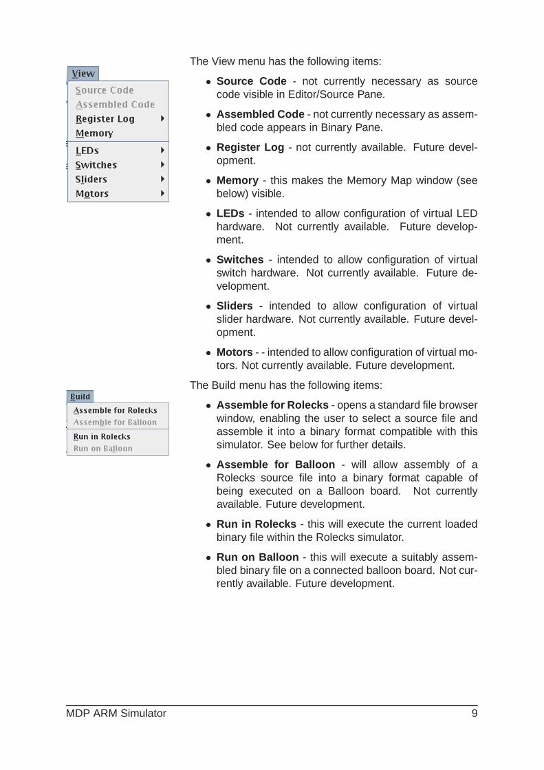
The View menu has the following items:
• Source Code - not currently necessary as sourcecode visible in Editor/Source Pane.
• Assembled Code - not currently necessary as assem-bled code appears in Binary Pane.
• Register Log - not currently available. Future devel-opment.
• Memory - this makes the Memory Map window (seebelow) visible.
• LEDs - intended to allow configuration of virtual LEDhardware. Not currently available. Future develop-ment.
• Switches - intended to allow configuration of virtualswitch hardware. Not currently available. Future de-velopment.
• Sliders - intended to allow configuration of virtualslider hardware. Not currently available. Future devel-opment.
• Motors - - intended to allow configuration of virtual mo-tors. Not currently available. Future development.
The Build menu has the following items:
• Assemble for Rolecks - opens a standard file browserwindow, enabling the user to select a source file andassemble it into a binary format compatible with thissimulator. See below for further details.
• Assemble for Balloon - will allow assembly of aRolecks source file into a binary format capable ofbeing executed on a Balloon board. Not currentlyavailable. Future development.
• Run in Rolecks - this will execute the current loadedbinary file within the Rolecks simulator.
• Run on Balloon - this will execute a suitably assem-bled binary file on a connected balloon board. Not cur-rently available. Future development.
MDP ARM Simulator 9

The Help menu has the following items:
• Online Help - not currently available. Future develop-ment.
• Code Structure - not currently available. Future de-velopment.
• Op-codes - not currently available. Future develop-ment.
• About Rolecks - displays a simple information boxgiving version and copyright information for the MDPARM Simulator.
3.1.2 Editor/Source Pane
The Editor/Source Pane is the left hand pane on the Simula-tor window. Its size is adjustable in width with a drag handleon the dividing bar. The pane is a simple editor designedto allow the user to enter and modify programs. Above it isa small menu bar that gives the user access via graphicalicons to key load, save and assemble functionality.
Editor Pane Icons
New Source Clears the current editor window. Warning:This does not prompt the user to save the current file, soselecting this option will delete any unsaved work.
Open File opens a standard file browser window andprompts the user to open a source file, N.B. source fileshave a suffix .s, e.g. example1.s
Save Source opens a standard file browser window andprompts the user for a filename to save the text currently inthe editor pane.
Assemble attempts to assemble a source file. By default, itoffers the user the currently saved version of the file in theeditor window.
Magic (SAL-B) attempts to save the text in the editor pane,under the currently selected filename, assemble the result-ing source file and, if successful, load the resultant binaryinto the binary pane.
10 MDP ARM Simulator

Editor FunctionalityThe editor has basic editing functionality, accessible fromcontrol keys and the pulldown Edit menu, in particular:
CTRL-A Select AllCTRL-C CopyCTRL-H Delete backwardsCTRL-V PasteCTRL-X DeleteDELETE Delete↑↓←→ Move cursor
3.1.3 Binary Pane
The Binary Pane displays the assembled binary file and sup-plemental information according to the following format of anotional memory address location (as a hexadecimal num-ber), followed by the actual instruction in its hexadecimalassembled representation, followed by the original sourceinstruction (minus any comments.) Any labels used in theprogram appear on a separate line preceding their associ-ated instruction for clarity. Neither assembler directives norany data areas appear in the Binary pane.
Binary Pane Icons
Open Binary File opens a standard file browser windowand prompts the user to open a binary file. N.B. Binary fileshave the suffix .bin, e.g. example1.bin
Reset terminates the execution of a currently running binaryprogram. It restores the Program Counter to the first line ofthe program, resets the values of registers R0 to R12 andR14 to zero, and clears the condition code bits.
Run executes the program from start to finish. Execution willonly pause if there is input required from the user. Duringexecution, the Run icon will be replaced with a Pause iconso that the program can be temporarily halted.
Pause freezes an executing program. It does not corruptregisters or condition code bits. Once a program is paused,the Pause icon is replaced with the Run icon, and the pro-gram may be restarted in single step mode or the systemreset.
Single Step allows the user to step through the programone instruction at a time each time the button is pressed.The light blue highlight bar indicates the instruction that isjust about to be run.
Breakpoint opens the Manage Breakpoints dialog win-
MDP ARM Simulator 11

dow that allows the user to set and clear breakpoints.Single-stepping through every line of a program can quicklybecome tedious; breakpoints allow individual lines to bemarked as being of interest. When a program has one ormore active breakpoints, the user can click on the Run but-ton (see above) and the program will execute until it reachesthe first breakpoint. Instead of immediately executing thebreakpoint instruction, it will pause at that instruction allow-ing the user to single-step at that point and beyond (to ob-serve register value and condition code changes) or to revertto continuous execution until the next breakpoint is encoun-tered. Active breakpoints are highlighted in the Binary Panewith yellow backgrounds. Whenever the instruction that isjust about to be run coincides with an active breakpoint, thehighlight bar will change to red for that instruction.
• New - this button allows for the setting of a new break-point. It raises the Add Breakpoint dialog, which re-quires the user to enter the hexadecimal address ofthe instruction where the breakpoint is to be placed.This address can be found by looking at the first col-umn of numbers in the Binary Pane. Click OK to addthe breakpoint, Cancel to refrain. Once a breakpoint isadded, the Manage Breakpoints dialog will change tolist the address of the breakpoint instruction, provide acheckbox (initially ticked) to show if the breakpoint isactive, and a Delete button to remove the breakpoint.
• Clear All - triggers a Yes/No confirmation dialog that, ifthe response is “Yes”, deletes all current breakpoints.
• Activate All - this makes all existing breakpoints active- as indicated by ticks appearing in the correspondingActive checkboxes for each breakpoint. To make a sin-gle breakpoint active simply check the appropriate Ac-tive checkbox.
• Deactivate All - - this makes all existing breakpointsinactive - as indicated by the absence of any tickmarksappearing in the corresponding Active checkboxes foreach breakpoint. To make a single breakpoint inactive,simply uncheck the appropriate Active checkbox.
• OK - this confirms all changes made and closes theManage Breakpoints dialog window.
• Cancel - this discards all changes made and closesthe Manage Breakpoints dialog window.
12 MDP ARM Simulator

3.1.4 Register Pane
The Register pane on the right of the main window is splitinto two main areas:
The upper region contains the current value of each ofthe standard 16 ARM registers. Values can be manuallychanged by clicking on the register or its value, which raisesa dialog window enabling a new value in hexadecimal to beentered.
The lower region displays the condition code bits:
• The N bit is the “negative flag” and indicates that avalue is negative.
• The Z bit is the “zero flag” and is set when an appro-priate instruction produces a zero result.
• The C bit is the “carry flag” but it can also be usedto indicate “borrows” (from subtraction operations) and“extends” (from shift instructions).
• The V bit is the “overflow flag” which is set if an instruc-tion produces a result that overflows and hence may gobeyond the range of numbers that can be representedin 2’s complement signed format.
The values can only currently be set or cleared during pro-gram execution, and reset to 0 using the Reset button.
MDP ARM Simulator 13

3.1.5 Text Entry Pane
(N.B. This section may be skipped on first reading)
The Text Entry Pane is divided into three sections.
• The upper section, Standard Output , is where text di-rected by assembler system calls is displayed. Thistext may be output as individual characters or as null-terminated strings. Users cannot change values dis-played in this area and it is only cleared when the sim-ulator is closed.
• The middle section, Standard Input , allows for key-board data entry to be entered independent of programexecution. Simply type in the characters and press theEnter/Return key to terminate the string, and the char-acters will appear in the Standard Input Buffer (see be-low).
• The lower section, Standard Input Buffer , storescharacters entered via Standard Input for use in pro-viding input to assembler system calls intended to readinput. The red X button will flush the contents of theStandard Input Buffer.
When a binary file executing in the MDP ARM Simulatormakes an assembler system call to obtain character or stringinput, the simulator first checks the Standard Input Buffer. Ifthe buffer is non-empty, the input will be taken directly fromthere. If the buffer is empty, then the Simulator will raise aStandard Input dialog window to obtain character input fromthe user at run-time.
3.2 Memory Map
(N.B. This section may be skipped on first reading)
This window, accessible via the view →Memory Map menuitem, provides a simulated view of part of an ARM processormemory map. The main portion of the map is taken up bya two-column list. The leftmost column of numbers are thememory address locations (in hexadecimal). The rightmostcolumn of numbers are the contents held in the associatedmemory address locations - these values may be instruc-tions, data or values held in the stack.
• Hex / Dec / Bin These radio buttons allow the con-tents of the memory address locations to be displayedin Hexadecimal, Decimal, or Bin ary representations.The memory address locations remain listed as hex-adecimal numbers.
14 MDP ARM Simulator
• Show Zero values Ticking this checkbox will show allmemory locations up to 0x3FC regardless of whetherthey contain zero or non-zero values. Clearing thecheckbox will hide all memory locations that have avalue of zero.
• Show Stack Ticking this checkbox will show all mem-ory locations that form the temporary memory storagearea known as the stack. Clearing the checkbox willhide these.
• Refresh Memory Map Pressing this button will refreshthe contents of the Memory Map – will require newcode to be loaded in to the Binary Pane and (partially)executed before the contents will update.
3.3 Hardware Simulation
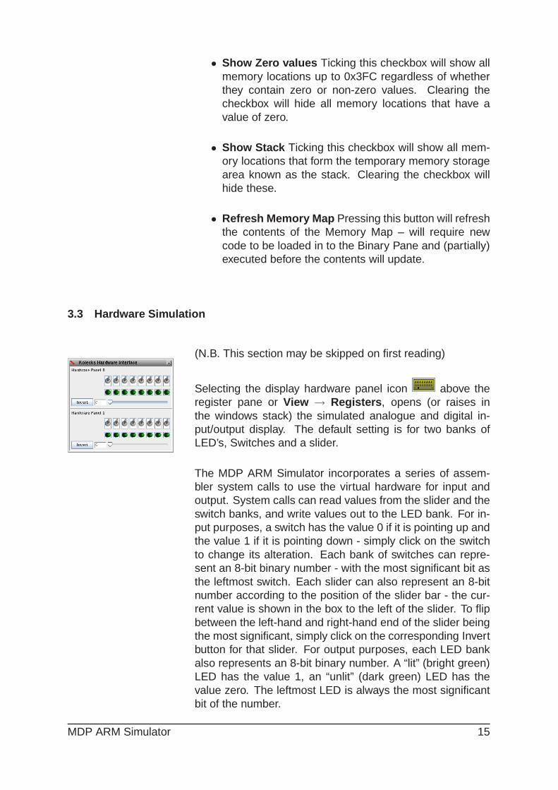
(N.B. This section may be skipped on first reading)
Selecting the display hardware panel icon above theregister pane or View → Registers , opens (or raises inthe windows stack) the simulated analogue and digital in-put/output display. The default setting is for two banks ofLED’s, Switches and a slider.
The MDP ARM Simulator incorporates a series of assem-bler system calls to use the virtual hardware for input andoutput. System calls can read values from the slider and theswitch banks, and write values out to the LED bank. For in-put purposes, a switch has the value 0 if it is pointing up andthe value 1 if it is pointing down - simply click on the switchto change its alteration. Each bank of switches can repre-sent an 8-bit binary number - with the most significant bit asthe leftmost switch. Each slider can also represent an 8-bitnumber according to the position of the slider bar - the cur-rent value is shown in the box to the left of the slider. To flipbetween the left-hand and right-hand end of the slider beingthe most significant, simply click on the corresponding Invertbutton for that slider. For output purposes, each LED bankalso represents an 8-bit binary number. A “lit” (bright green)LED has the value 1, an “unlit” (dark green) LED has thevalue zero. The leftmost LED is always the most significantbit of the number.
MDP ARM Simulator 15

4 Simple Programs
4.1 ‘Anatomy’ of a Program
1 ; Example code to load two registers
2 ; and then add them
34 AREA example1, CODE, READONLY
56 ENTRY
78 start
9 mov R0, #0x10 ; r0 = 10
10 mov R1, #10 ; r1 = a
11 add R2, R0, R1 ; r2 = 1a
1213 BL sysExit ; end of program
1415 END
The line numbers (in italics) have been added to this pro-gram purely for ease of explanation. There are no line num-bers in an ARM assembly language program; including linenumbers in the source code of an assembly language pro-gram will cause it to fail to assemble.
1 ; Example code to load two registers
2 ; and then add them
3
The first lines are comments, all text following a ; ona line is considered to be a comment. Although com-ments are optional, it is good programming practice to
include information about the code wherever possible. Thisis especially important in assembler programming where theformat and mnemonics are more difficult to understand anduse, especially when the author is trying to maximise speedor minimise memory space at execution time. Note that line3 is blank; the assembler ignores blank lines when assem-bling the source code, so they can be safely used to aid thereadability of the code.
4 AREA example1, CODE, READONLY
5
The AREA command is a directive . This is an instruc-tion to the assembler, which is not passed on to the
actual microprocessor. The AREA directive can be used tospecify and name sections of program code or data. Herethe AREA directive names this section as “example1” and in-dicates that it is a code segment using the CODE identifier.It is also declared as READONLY in that the code cannotbe altered during its execution. A working ARM assemblyprogram must have at least one CODE area.
16 MDP ARM Simulator
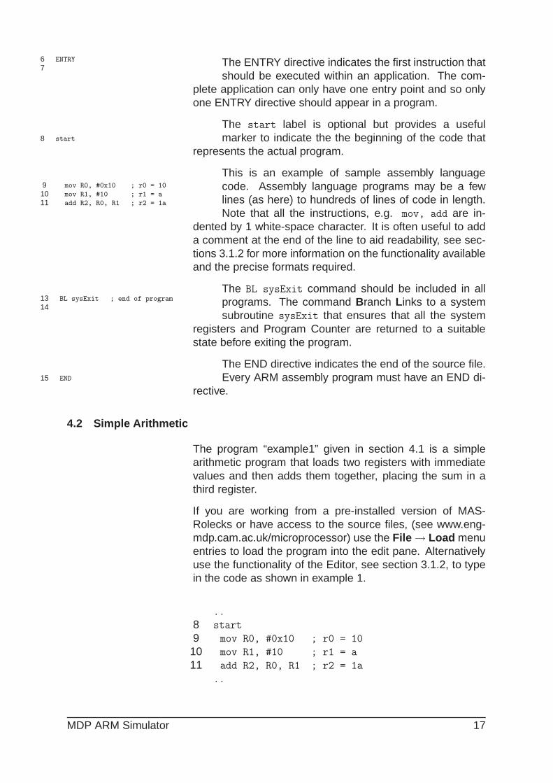
6 ENTRY
7The ENTRY directive indicates the first instruction thatshould be executed within an application. The com-
plete application can only have one entry point and so onlyone ENTRY directive should appear in a program.
8 start
The start label is optional but provides a usefulmarker to indicate the the beginning of the code that
represents the actual program.
9 mov R0, #0x10 ; r0 = 10
10 mov R1, #10 ; r1 = a
11 add R2, R0, R1 ; r2 = 1a
This is an example of sample assembly languagecode. Assembly language programs may be a fewlines (as here) to hundreds of lines of code in length.Note that all the instructions, e.g. mov, add are in-
dented by 1 white-space character. It is often useful to adda comment at the end of the line to aid readability, see sec-tions 3.1.2 for more information on the functionality availableand the precise formats required.
13 BL sysExit ; end of program
14
The BL sysExit command should be included in allprograms. The command Branch Links to a systemsubroutine sysExit that ensures that all the system
registers and Program Counter are returned to a suitablestate before exiting the program.
15 END
The END directive indicates the end of the source file.Every ARM assembly program must have an END di-
rective.
4.2 Simple Arithmetic
The program “example1” given in section 4.1 is a simplearithmetic program that loads two registers with immediatevalues and then adds them together, placing the sum in athird register.
If you are working from a pre-installed version of MAS-Rolecks or have access to the source files, (see www.eng-mdp.cam.ac.uk/microprocessor) use the File → Load menuentries to load the program into the edit pane. Alternativelyuse the functionality of the Editor, see section 3.1.2, to typein the code as shown in example 1.
..
8 start
9 mov R0, #0x10 ; r0 = 10
10 mov R1, #10 ; r1 = a
11 add R2, R0, R1 ; r2 = 1a
..
MDP ARM Simulator 17

9 mov R0, #0x10 ; r0 = 10 The instruction mov moves a value (in this case, thehexadecimal number 10, decimal value 16) into a reg-
ister (in this case, register r0). r0 and #10 are operands . r2is the destination register, #10 is a source operand.
10 mov R1, #10 ; r1 = a
In this line, the instruction mov moves the value (deci-mal 10) into a register, namely register 1.
11 add R2, R0, R1 ; r2 = 1a
The ADD instruction takes two source operands, inthis case register R0 and register R3, adds the values in theregisters, i.e. 10 in r0 and 16 in r1, and puts the total backinto the destination register of r2. Hence the value in R2 af-ter this instruction has been executed should be 26, or 1A inhexadecimal.
4.3 Assembling and Running Code
4.3.1 Writing New Source Files
To create a new source file from scratch in MAS-Rolecks,save any existing work in the Source/Editor pane using theFile → Save Source command, supplying an existing ornew file name as appropriate. Then use the File → NewSource command or the New Source icon to clear theSource/Editor Pane and start typing the program into theSource/Editor Pane. Remember to press Enter/Return aftereach line of code.
4.3.2 Loading Existing Source Files
To load an existing source file into MAS-Rolecks, simply usethe File → Load Source command or the Open File icon.(NB: Both methods will flush any existing source code.) Lo-cate the desired source file (which should have a .s suf-fix) using the file system browser dialog and click OK. Thesource file will appear in the Editor/Source pane.
4.3.3 Saving Source Files
To save a source file, use the File → Save Source com-mand or the Save Source icon. This will raise a file systembrowser dialog, allowing the file to be saved with its existingname (if any) or with a new name. In either case, the sourcefile should have a .s extension.
4.3.4 One-Click Assembly
To assemble a source file with a single mouse-click, use theMagic Wand icon. This will first save the text in the editorpane, under the currently selected filename if it exists (and
18 MDP ARM Simulator
will raise a file system dialog if not). It will then assemblethe resulting source file, raising a message window to signalsuccessful or unsuccessful assembly and information on thefirst error. In the latter case, rectify the errors in the sourcecode, save the file, and try again. If successful, it will finallyload the newly created binary file into the binary pane – thenew binary file will have the same name as the source buthave a .bin extension.
4.3.5 Two-Click Assembly
Use either the Assemble icon or the Build → Assemblefor Rolecks command to assemble a source file. This willraise a file system browser dialog, which will default to thecurrently saved version of the file in the Source/Editor pane.Choose the appropriate filename and click OK. A messagewindow will appear, either stating ”Source file assembledcorrectly” if there were no assembly errors or giving detailsof the first error encountered. In the latter case, rectify theerrors in the source code, save the file, and try again.
Once the source file has been successfully assembled, usethe File → Load Binary command or the Open Binary Fileicon (in the Binary Pane). This will raise a file system dialogwindow, which will default to the .bin file generated by themost recent assembly process. Click OK to load the binaryfile into the Binary Pane.
4.3.6 Running the Program
There are two methods of executing programs in MAS-Rolecks - “run-through” and “single-step”.
“Run-through” executes the entire program from start (orcurrently highlighted code) to finish. The execution will nor-mally only pause if an assembler system call is made forkeyboard input and no stored input in the Standard InputBuffer. To perform a “run-through” execution, use either theBuild → Run in Rolecks command or the Run icon abovethe Binary Pane. To forcibly suspend a program executingin “run-through” mode, click on the Pause icon (which re-places the Run icon). Execution can then be restarted fromthe pause point in either “run-through” or “single-step” modeor the system reset.
“Single-step” mode allows the user to step through the ex-ecution of the program one instruction at a time each timethe “Single step” icon is pressed. The light blue highlight barwill indicate the instruction that is just about to be executed.In “Single step” mode, it is possible to observe the values of
MDP ARM Simulator 19

the registers and condition code bits change in response toeach succeeding instruction.
The Reset button terminates the execution of a currently run-ning binary program. It restores the Program Counter to thefirst instruction of the program, resets the values of registersR0 to R12 and R14 to zero, and clears the condition codebits.
20 MDP ARM Simulator
4.4 Interaction Simulated Hardware
4.4.1 Switches
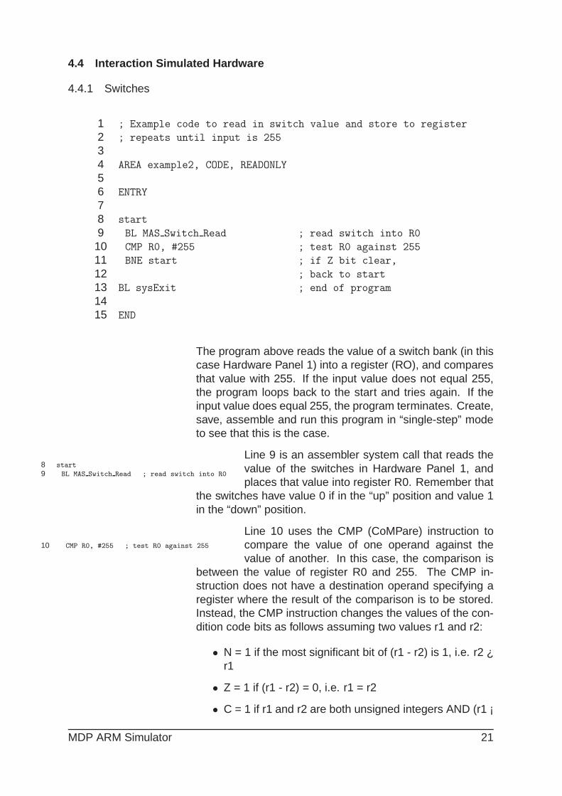
1 ; Example code to read in switch value and store to register
2 ; repeats until input is 255
34 AREA example2, CODE, READONLY
56 ENTRY
78 start
9 BL MAS Switch Read ; read switch into R0
10 CMP R0, #255 ; test R0 against 255
11 BNE start ; if Z bit clear,
12 ; back to start
13 BL sysExit ; end of program
1415 END
The program above reads the value of a switch bank (in thiscase Hardware Panel 1) into a register (RO), and comparesthat value with 255. If the input value does not equal 255,the program loops back to the start and tries again. If theinput value does equal 255, the program terminates. Create,save, assemble and run this program in “single-step” modeto see that this is the case.
8 start
9 BL MAS Switch Read ; read switch into R0
Line 9 is an assembler system call that reads thevalue of the switches in Hardware Panel 1, andplaces that value into register R0. Remember that
the switches have value 0 if in the “up” position and value 1in the “down” position.
10 CMP R0, #255 ; test R0 against 255
Line 10 uses the CMP (CoMPare) instruction tocompare the value of one operand against thevalue of another. In this case, the comparison is
between the value of register R0 and 255. The CMP in-struction does not have a destination operand specifying aregister where the result of the comparison is to be stored.Instead, the CMP instruction changes the values of the con-dition code bits as follows assuming two values r1 and r2:
• N = 1 if the most significant bit of (r1 - r2) is 1, i.e. r2 ¿r1
• Z = 1 if (r1 - r2) = 0, i.e. r1 = r2
• C = 1 if r1 and r2 are both unsigned integers AND (r1 ¡
MDP ARM Simulator 21

r2)
• V = 1 if r1 and r2 are both signed integers AND (r1 ¡r2)
For our example, Z will be set to 1 if R0 has the value 255and be clear otherwise. Observe the change in the conditioncode bits after this instruction is executed in “single-step”mode.
11 BNE start ; if Z bit clear,
12 ; back to start
13 BL sysExit ; end of program
The BNE (Branch Not Equal) instruction at Line 11inspects the current value of the Z condition codebit. If Z 6= 1, then the branch will be taken andthe execution of the program will return to the label
“start”. If Z = 1, then the branch will not be taken, and theprogram will carry on to line 13 and the termination of theprogram.
4.4.2 Sliders
1 ; Example code to read in slider value and store to register
2 ; repeats until input is 128 or higher
34 AREA example3, CODE, READONLY
56 ENTRY
78 start
9 BL MAS Slider Read ; read slider into R0
10 CMP R0, #128 ; test R0 against 128
11 BLO start ; if C bit clear,
12 ; back to start
13 BL sysExit ; end of program
1415 END
The program above reads the value of a slider (in this casefrom Hardware Panel 1) into a register (RO), and comparesthat value with 128. If the input value is less than 128, theprogram loops back to the start and tries again. If the in-put value is equal to or greater than 128, the program ter-minates. Create, save, assemble and run this program in“single-step” mode to see that this is the case.
8 start
9 BL MAS Slider Read ; read slider into R0
Line 9 is an assembler system call that reads thevalue of the slider in Hardware Panel 1, and placesthat value into register R0.
22 MDP ARM Simulator
10 CMP R0, #128 ; test R0 against 128 Line 10 uses the CMP (CoMPare) instruction tocompare the value of one operand against the
value of another. In this case, the comparison is betweenthe value of register R0 and 128. The CMP instruction willalter the condition code bits as described above. In this ex-ample, we are interested in the value of the C bit, which willbe cleared (set at 0) if the input (in R0) is less than 128,and set to 1 if the value of R0 is 128 or more. Note that theother condition code bits may also be changed by the CMPinstruction.
11 BLO start ; if C bit clear,
12 ; back to start
13 BL sysExit ; end of program
The BLO (Branch if LOwer) instruction at Line 11inspects the current value of the C condition codebit. If C = 0, then the branch will be taken andthe execution of the program will return to the label
“start”. If C = 1, then the branch will not be taken, and theprogram will carry on to line 13 and the termination of theprogram.
4.4.3 LEDs
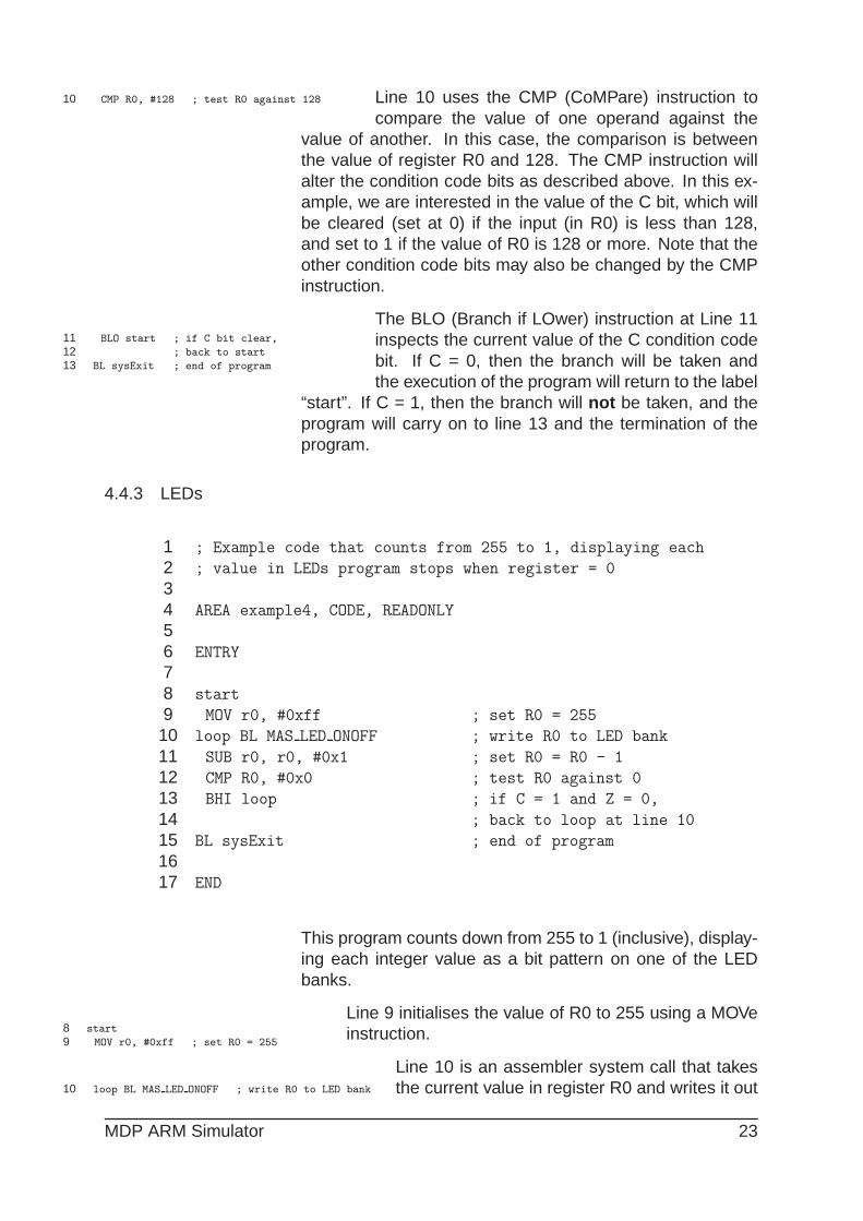
1 ; Example code that counts from 255 to 1, displaying each
2 ; value in LEDs program stops when register = 0
34 AREA example4, CODE, READONLY
56 ENTRY
78 start
9 MOV r0, #0xff ; set R0 = 255
10 loop BL MAS LED ONOFF ; write R0 to LED bank
11 SUB r0, r0, #0x1 ; set R0 = R0 - 1
12 CMP R0, #0x0 ; test R0 against 0
13 BHI loop ; if C = 1 and Z = 0,
14 ; back to loop at line 10
15 BL sysExit ; end of program
1617 END
This program counts down from 255 to 1 (inclusive), display-ing each integer value as a bit pattern on one of the LEDbanks.
8 start
9 MOV r0, #0xff ; set R0 = 255
Line 9 initialises the value of R0 to 255 using a MOVeinstruction.
10 loop BL MAS LED ONOFF ; write R0 to LED bank
Line 10 is an assembler system call that takesthe current value in register R0 and writes it out
MDP ARM Simulator 23
to one of the LED banks in the Virtual Hardware Interface, inthis case Hardware Panel 1. Note that Line 10 has its ownlabel, “loop”.
11 SUB r0, r0, #0x1 ; set R0 = R0 - 1
Line 11 uses the SUB instruction to decrementthe value of R0 by 1. The SUB instruction sub-
tracts 1 (the second source operand) from the value in thefirst source operand (here R0), and places the new valueback into R0
12 CMP R0, #0x0 ; test R0 against 0
13 BHI loop ; if C = 1 and Z = 0,
13 ; back to loop at line 10
Line 12 uses the CMP instruction to comparethe values of R0 and 0. In this example, we willbe interested in the value of the Z and the C bits.Line 13 is a BHI (Branch if HIgher) instruction.
If the value of C is 1 and Z is 0 (which occurs if R0 > 0) thenthe program branches back to the “loop” label at line 10. Ifnot, then the branch is not taken and the program proceedsto line 15 and termination.
4.5 Textual I/O
4.5.1 Text Input
4.5.2 Text Output
4.6 Use of Memory Map
- memory map and what can be seen
4.7 Modification of Registers
- update of registers - watch as happens or inject differentvalues in single-step
24 MDP ARM Simulator

5 Simplified ARM Assembler
Internally the ARM uses 32 bit instructions which are gen-erally called from an assembler using a relatively standardOpcode format. The syntax used in MAS Rolecks is simi-lar to those found in other ARM assemblers, e.g. ADS, Kile.Details of individual formats/syntax can be found in Appen-dicies ?? , however the general construction is shown in thefollowing sections.
5.1 Instruction Syntax
Opcode Flags Operand 1⇓ ⇓ ⇓
ADD EQ S R0, R1, R2, LSL#2⇑ ⇑ ⇑
Condition Destination Operand 2Code Register
Where
Opcode Typically a 3 letter mnemomic, common codes usedbelow, see Appendix ?? for full details
Mnemonic Description Example Mnemonic Description ExampleADC Add with Carry ADC R0, R1, #1 MOV Move MOV R0, #0x07ADD Add ADD R0, R1, R2 ORR Logical OR ORR R0, R1AND Logical And AND R0, R0, #0xFF STR Store Register STR R0, [R1]
B Branch B loop SUB Subtract SUB R0, R1, R2BL Branch Link BL mas leds onoff TEQ Test equivalence TEQ R1, R2
CMP Compare CMP R0, R1LDR Load Register LDR R0, [R1]
Condition Code indicates what conditions are inspected prior to action-ing the instructions, see Appendix ?? for more details.
Mnemonic Meaning Status Flags Mnemonic Meaning Status FlagsEQ EQual Z=1 VC oVerflow Clear V=1NE Not Equal Z=0 HI unsigned HIgher C=1,Z=0CS Carry Set C=1 LS unsigned Lower or Same C=0, Z=1CC Carry Clear C=0 GE signed Greater than or Equal N=VHS Higher or Same C=1 LT signed Less Than N!=VLO unsigned LOwer C=0 GT signed Greater Than Z=0, N=VMI MInus/negative N=1 LE signed Less than or Equal Z=1,N!=VPl PLus/positive N=0 AL ALways -VS oVerflow Set V=1 NE NEver -
Status Flag Adding S to the opcode ensures that the status flagsare updated when the instruction is actioned.
Destination Register Typically R0→ R12
Operand 1 Normally a register ( R0→ R12)
Operand 2 Normally an optional parameter, but typically one ofthe following formats.
MDP ARM Simulator 25

– Immediate e.g. #0x23 (35)
– Register e.g. R2
– Resister + barrel Shifter e.g. R2, LSL#2 (4*R2)
5.2 Instruction Types
There are five general types of instructions/opcodes:-
Data operations (For further information see Appendix ?? )
This group does most of the work. There are sixteeninstructions, and they have very similar formats. Ex-amples of instructions from this group are ADD andCMP, which add and compare two numbers respec-tively. The operands of these instructions are alwaysin registers (or an immediate number stored in the in-struction itself), never in memory.
Load and Store (For further information see Appendix ?? )
Group of two instructions: load a register and savea register, with a number of variations which includewhether bytes or words are transferred, and how thememory location to be used is obtained.
Multiple Load and Store Group of instructions that allows between one and16 registers to be moved between the processor andmemory. Only word transfers are performed by thisgroup.
Branching Although the PC may be altered using the data oper-ations to cause a change in the program counter, thebranch instruction provides a convenient way of reach-ing any part of the 64M byte address space in a singleinstruction. It causes a displacement to be added tothe current value of the PC. The displacement is storedin the instruction itself.
SWI This one-instruction group is very important. The ab-breviation stands for ’SoftWare Interrupt’. It providesthe way for user’s programs to access the facilities pro-vided by the operating system. All ARM -based com-puters provide a certain amount of pre-written softwareto perform such tasks as printing characters on to thescreen, performing disc I/O etc. By issuing SWI in-structions, the user’s program may utilise this operat-ing system software, obviating the need to write theroutines for each application.
26 MDP ARM Simulator

6 MAS Rolecks Assembler Functions
ADD NOTES ABOUT SWI/BL
The documentation that follows tries to copy the ARM styledocumentation for SWIs as much as possible. Notable ex-ceptions are the lack of a SWI number. These are function-like calls that are invokes using a BL (branch-link) instruc-tion, possibly with a conditional suffix. Note that these rou-tines differ from C functions in that they may return values inanLine 8: ; and store the total back into register
2
6.1 System operations
MAS-Rolecks implements a number of system level callssimilar to other ARM asssemblers, the operation of thosecommonly used are given below and a the full list is given inappendix ?? .
6.1.1 SYS Exit
Terminates the current program
On Entry R1 contains the return code for the program
On Exit This routine does not return
6.1.2 SYS ReadC
Reads a byte from the standard input.
On Entry Register R1 must contain zero. There are no otherparameters or values possible.
On Exit R0 contains the byte read from the console.
6.1.3 SYS WriteC
Writes a character byte, contained in R1, to the standardoutputl.
On Entry R1 contains the character.
On Exit None. Register R0 is corrupted.
Comment This differs from ADS SYS WriteC, where R1 is apointer to the byte.
MDP ARM Simulator 27
6.2 Hardware i/o Routines
In addition to the standard ARM consistan i/o functions MASalso has a number of routines that can be called as subrou-tines that access simulated or real hardware (if connected orrunning on a MDP Balloon system) A full list of the availablefunctions is given in appendix ?? . The calls allow accessto hardware at various depth levels, but the normal user islikely to use the high level varieties that are listed below andwork directly with the simulated hardware describe din sec-tion ??
6.2.1 MAS LED OnOff
Sets LED states to either on or of in a banks of 8 LEDs at atime.
On Entry – R0 contains in bits 0 to 7 the new state of the 8LEDs in the bank indicated by R1
– R1 contains the LED bank number
On Exit – R0 contains 0 if the operation was successful and-1 otherwise
– R1 is preserved
6.2.2 MAS Slider Read
Reads the current state of the analogue slide control
On Entry R1 contains the slider number (usually 0)
On Exit R0 contains the slider value in bits 15..0
Comments On exit R0 will contain a 16-bit number, but it shouldnot be assumed that the ADC that took the reading is16-bit. The lower bits could be 0.
6.2.3 MAS Switch Read
Reads the current state of a bank of up to 8 switches
On Entry R1 contains the switch bank number
On Exit R0 contains the switch settings in bits 7..0
28 MDP ARM Simulator

Appendices
A ARM Assembler Opcodes
A.1 Data Operations - Arithmetic
A.1.1 ADD ADD
Syntax ADD <cc> <S> Rd, Rn, <Op1>
Description <Rd> = <Rn> + <Op1>
Add the value of <Op1> to register Rn and store theresult in Rd.
ExampleADD R0, R0,#1 ;Increment RO
ADD R1, R1, R1, LSL#2 ;R1*5
ADDS R0, R1, R2 ;R0=R1+R2, check for overflow
Condition Codes The N and Z flags are set on the result of the addition.The C and V flags are set dependent on whether thethe addition generated a carry (unsigned overflow) ora signed overflow.
Instruction Format
Opcode 31302928272625242322212019181716151413121110 9 8 7 6 5 4 3 2 1 0
ADD<cond><S> Rd, Rn, # cond 0 0 1 0 1 0 0 S Rn Rd rotate #
ADD<cond><S> Rd, Rn, Rm OP # cond 0 0 0 0 1 0 0 S Rn Rd shift# shift 0 Rm
ADD<cond><S> Rd, Rn, Rm OP Rs cond 0 0 0 0 1 0 0 S Rn Rd Rs 0 shift 1 Rm
A.1.2 ADC ADD with Carry
Syntax ADC <cc> <S> Rd, Rn, <Op1>
Description <Rd> = <Rn> + <Op1>+ <Carry>
Used in a similar fashion to ADD but with the carryadded into the result as well dependant on <op1>
Example ;add the 64-bit number in R2, R3
;to that in R0, R1
ADDS R0, R0, R2 ;Add the lower words
ADC R1, R1, R3 ;Add upper words using carry
N.B setting the final line to
ADCS R1, R1, R3 ;Add upper words using carry
;Set Flags
MDP ARM Simulator 29
results in the flags being set if:-N The 64-bit result was negativeC Unsigned overflow occurredV signed overflow occurredZ The top 32 bits are zero
Condition Codes The N and Z flags are set on the result of the addition.The C and V flags are set dependent on whether thethe addition generated a carry (unsigned overflow) ora signed overflow.
Instruction Format
Opcode 31302928272625242322212019181716151413121110 9 8 7 6 5 4 3 2 1 0
ADC<cond><S> Rd, Rn, # cond 0 0 1 0 1 0 1 S Rn Rd rotate #
ADC<cond><S> Rd, Rn, Rm OP # cond 0 0 0 0 1 0 1 S Rn Rd shift# shift 0 Rm
ADC<cond><S> Rd, Rn, Rm OP Rs cond 0 0 0 0 1 0 1 S Rn Rd Rs 0 shift 1 Rm
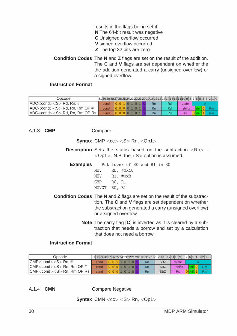
A.1.3 CMP Compare
Syntax CMP <cc> <S> Rn, <Op1>
Description Sets the status based on the subtraction <Rn> -<Op1>. N.B. the <S> option is assumed.
Examples ; Put lower of R0 and R1 in R0
MOV RO, #0x10
MOV R1, #0x8
CMP R0, R1
MOVGT R0, R1
Condition Codes The N and Z flags are set on the result of the substrac-tion. The C and V flags are set dependent on whetherthe substraction generated a carry (unsigned overflow)or a signed overflow.
Note The carry flag [C] is inverted as it is cleared by a sub-traction that needs a borrow and set by a calculationthat does not need a borrow.
Instruction Format
Opcode 31302928272625242322212019181716151413121110 9 8 7 6 5 4 3 2 1 0
CMP<cond><S> Rn, # cond 0 0 1 1 0 1 0 S Rn SBZ rotate #
CMP<cond><S> Rn, Rm OP # cond 0 0 0 1 0 1 0 S Rn SBZ shift# shift 0 Rm
CMP<cond><S> Rn, Rm OP Rs cond 0 0 0 1 0 1 0 S Rn SBZ Rs 0 shift 1 Rm
A.1.4 CMN Compare Negative
Syntax CMN <cc> <S> Rn, <Op1>
30 MDP ARM Simulator
Description Sets the status based on the subtraction Rn - - <Op1>
= Rn + <Op1>. N.B. the <S> option is assumed.
Examples CMP R0, #0x5 ; Compare R0 with -5
Condition Codes The N and Z flags are set on the result of the substrac-tion. The C and V flags are set dependent on whetherthe substraction generated a carry (unsigned overflow)or a signed overflow.
Note The carry flag [C] is inverted as it is cleared by a sub-traction that needs a borrow and set by a calculationthat does not need a borrow.
Instruction Format
Opcode 31302928272625242322212019181716151413121110 9 8 7 6 5 4 3 2 1 0
CMN<cond><S> Rn, # cond 0 0 1 1 0 1 1 S Rn SBZ rotate #
CMN<cond><S> Rn, Rm OP # cond 0 0 0 1 0 1 1 S Rn SBZ shift# shift 0 Rm
CMN<cond><S> Rn, Rm OP Rs cond 0 0 0 1 0 1 1 S Rn SBZ Rs 0 shift 1 Rm
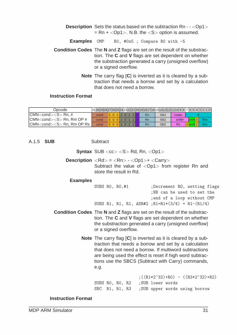
A.1.5 SUB Subtract
Syntax SUB <cc> <S> Rd, Rn, <Op1>
Description <Rd> = <Rn> - <Op1>+ <Carry>
Subtract the value of <Op1> from register Rn andstore the result in Rd.
ExamplesSUBS R0, R0,#1 ;Decrement RO, setting flags
;NB can be used to set the
;end of a loop without CMP
SUBS R1, R1, R1, ASR#2 ;R1=R1*(3/4) = R1-(R1/4)
Condition Codes The N and Z flags are set on the result of the substrac-tion. The C and V flags are set dependent on whetherthe substraction generated a carry (unsigned overflow)or a signed overflow.
Note The carry flag [C] is inverted as it is cleared by a sub-traction that needs a borrow and set by a calculationthat does not need a borrow. If multiword subtractionsare being used the effect is reset if high word subtrac-tions use the SBCS (Subtract with Carry) commands,e.g.
;((R1*2^32)+R0) - ((R3*2^32)+R2)
SUBS R0, R0, R2 ;SUB lower words
SBC R1, R1, R3 ;SUB upper words using borrow
Instruction Format
MDP ARM Simulator 31

Opcode 31302928272625242322212019181716151413121110 9 8 7 6 5 4 3 2 1 0
SUB<cond><S> Rd, Rn, # cond 0 0 1 0 0 1 0 S Rn Rd rotate #
SUB<cond><S> Rd, Rn, Rm OP # cond 0 0 0 0 0 1 0 S Rn Rd shift# shift 0 Rm
SUB<cond><S> Rd, Rn, Rm OP Rs cond 0 0 0 0 0 1 0 S Rn Rd Rs 0 shift 1 Rm
A.1.6 SBC Subtract with Carry
Syntax SBC <cc> <S> Rd, Rn, <Op1>
Description <Rd> = <Rn> - <Op1> - NOT(<Carry>)Used in multiword subtractionsa similar fashion to ADD
but with the carry added into the result as well depen-dant on <op1>
Example ;((R1*2^32)+R0) - ((R3*2^32)+R2)
SUBS R0, R0, R2 ;SUB lower words
SBC R1, R1, R3 ;SUB upper words using borrow
Condition Codes The N and Z flags are set on the result of the substrac-tion. The C and V flags are set dependent on whetherthe substraction generated a carry (unsigned overflow)or a signed overflow.
Note The carry flag [C] is inverted as it is cleared by a sub-traction that needs a borrow and set by a calculationthat does not need a borrow. If multiword subtractionsare being used the effect is reset if high word subtrac-tions use the SBCS (Subtract with Carry) commands.
Instruction Format
Opcode 31302928272625242322212019181716151413121110 9 8 7 6 5 4 3 2 1 0
SBC<cond><S> Rd, Rn, # cond 0 0 1 0 1 1 0 S Rn Rd rotate #
SBC<cond><S> Rd, Rn, Rm OP # cond 0 0 0 0 1 1 0 S Rn Rd shift# shift 0 Rm
SBC<cond><S> Rd, Rn, Rm OP Rs cond 0 0 0 0 1 1 0 S Rn Rd Rs 0 shift 1 Rm
A.1.7 RSB Reverse Subtract
Syntax RSB <cc> <S> Rd, Rn, <Op1>
Description <Rd> = <Op1> - <Rn>
Subtract the value of register Rn from <Op1> andstore the result in Rd, which allows the operands inOp1 to be used in subtractions.
ExamplesRSB R0, R0, #1 ;RO = 1 - RO
RSB R0, R0, R0, ASL#4 ;R0= 15*R0 = (16*R0)-R0
32 MDP ARM Simulator

Condition Codes The N and Z flags are set on the result of the substrac-tion. The C and V flags are set dependent on whetherthe substraction generated a carry (unsigned overflow)or a signed overflow.
Note The carry flag [C] is inverted as it is cleared by a sub-traction that needs a borrow and set by a calculationthat does not need a borrow. If multiword subtractionsare being used the effect is reset if high word sub-tractions use the RSCS (Reverse Subtract with Carry)commands.
Instruction Format
Opcode 31302928272625242322212019181716151413121110 9 8 7 6 5 4 3 2 1 0
RSB<cond><S> Rd, Rn, # cond 0 0 1 0 0 1 1 S Rn Rd rotate #
RSB<cond><S> Rd, Rn, Rm OP # cond 0 0 0 0 0 1 1 S Rn Rd shift# shift 0 Rm
RSB<cond><S> Rd, Rn, Rm OP Rs cond 0 0 0 0 0 1 1 S Rn Rd Rs 0 shift 1 Rm
A.1.8 RSC Reverse Subtract with Carry
Syntax RSC <cc> <S> Rd, Rn, <Op1>
Description <Rd> = <Op1> - <Rn> - NOT(<Carry>)Used in multiword subtractionsa similar fashion to RSB
but with the carry added into the result as well depen-dant on <op1>
Example ;((R2*2^32)+16) - ((R1*2^32)+R0)
RSBS R0, R0, #0x10 ;SUB lower words
RSC R1, R1, R2 ;SUB upper words
Condition Codes The N and Z flags are set on the result of the substrac-tion. The C and V flags are set dependent on whetherthe substraction generated a carry (unsigned overflow)or a signed overflow.
Instruction Format
Opcode 31302928272625242322212019181716151413121110 9 8 7 6 5 4 3 2 1 0
RSC<cond><S> Rd, Rn, # cond 0 0 1 0 1 1 1 S Rn Rd rotate #
RSC<cond><S> Rd, Rn, Rm OP # cond 0 0 0 0 1 1 1 S Rn Rd shift# shift 0 Rm
RSC<cond><S> Rd, Rn, Rm OP Rs cond 0 0 0 0 1 1 1 S Rn Rd Rs 0 shift 1 Rm
A.2 Data Operations - Logical
A.2.1 AND Logical AND
Syntax AND <cc> <S> Rd, Rn, <Op1>
MDP ARM Simulator 33
Description Performs a full 32 bitwise AND on Rn with the value of<Op1>, storing the result in Rn.
Rn <Op1> Rd0 0 00 1 01 0 01 1 1
ExampleANDS R0, R0, R1 ;Mask R0 with R1
AND R0, R0, #0xDF ;Set ASCII code to upper case
Condition Codes The N and Z flags are set on the result of the ANDoperation. The C flag is set but the V flag is untouched.
Instruction Format
Opcode 31302928272625242322212019181716151413121110 9 8 7 6 5 4 3 2 1 0
AND<cond><S> Rd, # cond 0 0 1 0 0 0 0 S Rn Rd rotate #
AND<cond><S> Rd, Rm OP # cond 0 0 0 0 0 0 0 S Rn Rd shift# shift 0 Rm
AND<cond><S> Rd, Rm OP Rs cond 0 0 0 0 0 0 0 S Rn Rd Rs 0 shift 1 Rm
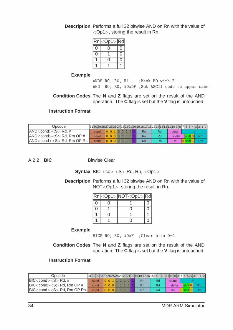
A.2.2 BIC Bitwise Clear
Syntax BIC <cc> <S> Rd, Rn, <Op1>
Description Performs a full 32 bitwise AND on Rn with the value ofNOT<Op1>, storing the result in Rn.
Rn <Op1> NOT<Op1> Rd
0 0 1 00 1 0 01 0 1 11 1 0 0
ExampleBICS R0, R0, #0xF ;Clear bits 0-4
Condition Codes The N and Z flags are set on the result of the ANDoperation. The C flag is set but the V flag is untouched.
Instruction Format
Opcode 31302928272625242322212019181716151413121110 9 8 7 6 5 4 3 2 1 0
BIC<cond><S> Rd, # cond 0 0 1 1 1 1 0 S Rn Rd rotate #
BIC<cond><S> Rd, Rm OP # cond 0 0 0 1 1 1 0 S Rn Rd shift# shift 0 Rm
BIC<cond><S> Rd, Rm OP Rs cond 0 0 0 1 1 1 0 S Rn Rd Rs 0 shift 1 Rm
34 MDP ARM Simulator
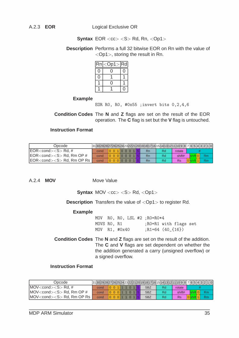
A.2.3 EOR Logical Exclusive OR
Syntax EOR <cc> <S> Rd, Rn, <Op1>
Description Performs a full 32 bitwise EOR on Rn with the value of<Op1>, storing the result in Rn.
Rn <Op1> Rd0 0 00 1 11 0 11 1 0
ExampleEOR R0, R0, #0x55 ;invert bits 0,2,4,6
Condition Codes The N and Z flags are set on the result of the EORoperation. The C flag is set but the V flag is untouched.
Instruction Format
Opcode 31302928272625242322212019181716151413121110 9 8 7 6 5 4 3 2 1 0
EOR<cond><S> Rd, # cond 0 0 1 0 0 0 1 S Rn Rd rotate #
EOR<cond><S> Rd, Rm OP # cond 0 0 0 0 0 0 1 S Rn Rd shift# shift 0 Rm
EOR<cond><S> Rd, Rm OP Rs cond 0 0 0 0 0 0 1 S Rn Rd Rs 0 shift 1 Rm
A.2.4 MOV Move Value
Syntax MOV <cc> <S> Rd, <Op1>
Description Transfers the value of <Op1> to register Rd.
ExampleMOV R0, R0, LSL #2 ;R0=R0*4
MOVS R0, R1 ;R0=R1 with flags set
MOV R1, #0x40 ;R1=64 (40_{16})
Condition Codes The N and Z flags are set on the result of the addition.The C and V flags are set dependent on whether thethe addition generated a carry (unsigned overflow) ora signed overflow.
Instruction Format
Opcode 31302928272625242322212019181716151413121110 9 8 7 6 5 4 3 2 1 0
MOV<cond><S> Rd, # cond 0 0 1 1 1 0 1 S SBZ Rd rotate #
MOV<cond><S> Rd, Rm OP # cond 0 0 0 1 1 0 1 S SBZ Rd shift# shift 0 Rm
MOV<cond><S> Rd, Rm OP Rs cond 0 0 0 1 1 0 1 S SBZ Rd Rs 0 shift 1 Rm
MDP ARM Simulator 35
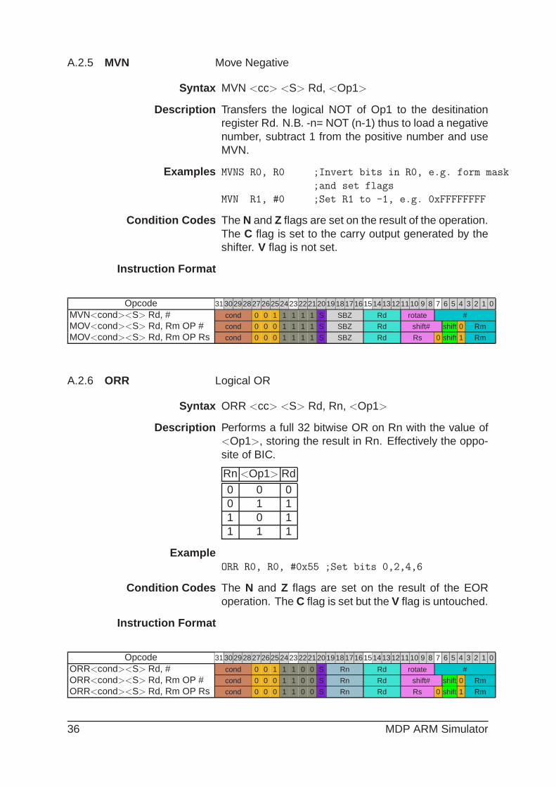
A.2.5 MVN Move Negative
Syntax MVN <cc> <S> Rd, <Op1>
Description Transfers the logical NOT of Op1 to the desitinationregister Rd. N.B. -n= NOT (n-1) thus to load a negativenumber, subtract 1 from the positive number and useMVN.
Examples MVNS R0, R0 ;Invert bits in R0, e.g. form mask
;and set flags
MVN R1, #0 ;Set R1 to -1, e.g. 0xFFFFFFFF
Condition Codes The N and Z flags are set on the result of the operation.The C flag is set to the carry output generated by theshifter. V flag is not set.
Instruction Format
Opcode 31302928272625242322212019181716151413121110 9 8 7 6 5 4 3 2 1 0
MVN<cond><S> Rd, # cond 0 0 1 1 1 1 1 S SBZ Rd rotate #
MOV<cond><S> Rd, Rm OP # cond 0 0 0 1 1 1 1 S SBZ Rd shift# shift 0 Rm
MOV<cond><S> Rd, Rm OP Rs cond 0 0 0 1 1 1 1 S SBZ Rd Rs 0 shift 1 Rm
A.2.6 ORR Logical OR
Syntax ORR <cc> <S> Rd, Rn, <Op1>
Description Performs a full 32 bitwise OR on Rn with the value of<Op1>, storing the result in Rn. Effectively the oppo-site of BIC.
Rn <Op1> Rd
0 0 00 1 11 0 11 1 1
ExampleORR R0, R0, #0x55 ;Set bits 0,2,4,6
Condition Codes The N and Z flags are set on the result of the EORoperation. The C flag is set but the V flag is untouched.
Instruction Format
Opcode 31302928272625242322212019181716151413121110 9 8 7 6 5 4 3 2 1 0
ORR<cond><S> Rd, # cond 0 0 1 1 1 0 0 S Rn Rd rotate #
ORR<cond><S> Rd, Rm OP # cond 0 0 0 1 1 0 0 S Rn Rd shift# shift 0 Rm
ORR<cond><S> Rd, Rm OP Rs cond 0 0 0 1 1 0 0 S Rn Rd Rs 0 shift 1 Rm
36 MDP ARM Simulator

A.2.7 TEQ Test Equivalence
Syntax TEQ <cc> <S> Rn, <Op1>
Description Performs a full 32 bitwise EOR on Rn and <Op1> butonly only sets the result flags. N.B. the option <S> isassumed.
ExampleTEQ R1, #0x15 ;Check if R1=21
Condition Codes The Z flag is set if the two operands are equal.
Instruction Format
Opcode 31302928272625242322212019181716151413121110 9 8 7 6 5 4 3 2 1 0
TEQ<cond><S> Rn, # cond 0 0 1 1 0 0 1 S Rn SBZ rotate #
TEQ<cond><S> Rn, Rm OP # cond 0 0 0 1 0 0 1 S Rn SBZ shift# shift 0 Rm
TEQ<cond><S> Rn, Rm OP Rs cond 0 0 0 1 0 0 1 S Rn SBZ Rs 0 shift 1 Rm
A.2.8 TST Test Bits
Syntax TST <cc> <S> Rn, <Op1>
Description Performs a full 32 bitwise AND on Rn and <Op1> butonly only sets the result flags. N.B. the option <S> isassumed.
ExampleTEQ R1, #0x1 ;Check if R1 bit 8 is set
Condition Codes The Z flag is set if the two operands are equal.
Instruction Format
Opcode 31302928272625242322212019181716151413121110 9 8 7 6 5 4 3 2 1 0
TST<cond><S> Rn, # cond 0 0 1 1 0 0 0 S Rn SBZ rotate #
TST<cond><S> Rn, Rm OP # cond 0 0 0 1 0 0 0 S Rn SBZ shift# shift 0 Rm
TST<cond><S> Rn, Rm OP Rs cond 0 0 0 1 0 0 0 S Rn SBZ Rs 0 shift 1 Rm
A.3 Load and Store
A.3.1 LDR Load Register
Syntax LDR <cc> Rd, <Op2> <!>
Description load the register Rd with a word from the memory lo-cation calculated by <Op2>. If PC (R15) is used asthe Rd the program branches to the address specifiedin <Op2>.
Examples Pre-indexing
MDP ARM Simulator 37
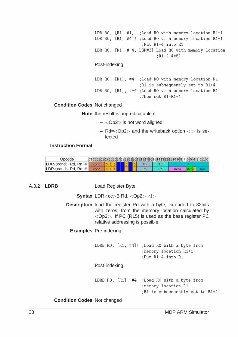
LDR R0, [R1, #1] ;Load R0 with memory location R1+1
LDR R0, [R1, #4]! ;Load R0 with memory location R1+1
;Put R1+4 into R1
LDR R0, [R1, #-4, LSR#3];Load R0 with memory location
;R1+(-4*8)
Post-indexing
LDR R0, [R1], #4 ;Load R0 with memory location R1
;R1 is subsequently set to R1+4
LDR R0, [R1], #-4 ;Load R0 with memory location R1
;Then set R1=R1-4
Condition Codes Not changed
Note the result is unpredicatable if:-
– <Op2> is not word aligned
– Rd=<Op2> and the writeback option <!> is se-lected
Instruction Format
Opcode 31302928272625242322212019181716151413121110 9 8 7 6 5 4 3 2 1 0
LDR<cond> Rd, Rn, # cond 0 1 0 P U 0 W 0 Rn Rd #
LDR<cond> Rd, Rn, # cond 0 1 1 P U 0 W 0 Rn Rd shift# shift 0 Rm
A.3.2 LDRB Load Register Byte
Syntax LDR<cc>B Rd, <Op2> <!>
Description load the register Rd with a byte, extended to 32bitswith zeros, from the memory location calculated by<Op2>. If PC (R15) is used as the base register PCrelative addressing is possible.
Examples Pre-indexing
LDRB R0, [R1, #4]! ;Load R0 with a byte from
;memory location R1+1
;Put R1+4 into R1
Post-indexing
LDRB R0, [R1], #4 ;Load R0 with a byte from
;memory location R1
;R1 is subsequently set to R1+4
Condition Codes Not changed
38 MDP ARM Simulator

Note the result is unpredicatable if:-
– Rd=15 (PC)
– Rd=<Op2> and the writeback option <!> is se-lected
Instruction Format
Opcode 31302928272625242322212019181716151413121110 9 8 7 6 5 4 3 2 1 0
LDR<cond>B Rd, Rn, # cond 0 1 0 P U 1 W 0 Rn Rd #
LDR<cond>B Rd, Rn, # cond 0 1 1 P U 1 W 0 Rn Rd shift# shift 0 Rm
A.3.3 STR Store Register
Syntax STR <cc> Rd, <Op2> <!>
Description Store the register Rd in the memory location calculatedby <Op2>. If PC (R15) is used as the base register al-lows position independant code using PC-relative ad-dressing.
Examples Pre-indexing
STR R0, [R1, #4]! ;Store R0 in memory location
;R1+4, Put R1+4 into R1
STR R0, [R1, #-4, LSR#3] ;Store R0 in memory
;location R1+(-4*8)
Post-indexing
STR R0, [R1], #4 ;Store R0 in memory location R1
;R1 is subsequently set to R1+4
STR R0, [R1], #-8 ;Store R0 in memory location R1
;Then set R1=R1-8
Condition Codes Not changed
Note the result is unpredicatable if:-
– <Op2> is not word aligned
– Rd=<Op2> and the writeback option <!> is se-lected
Instruction Format
Opcode 31302928272625242322212019181716151413121110 9 8 7 6 5 4 3 2 1 0
STR<cond> Rd, Rn, # cond 0 1 0 P U 0 W 0 Rn Rd #
STR<cond> Rd, Rn, # cond 0 1 1 P U 0 W 0 Rn Rd shift# shift 0 Rm
MDP ARM Simulator 39
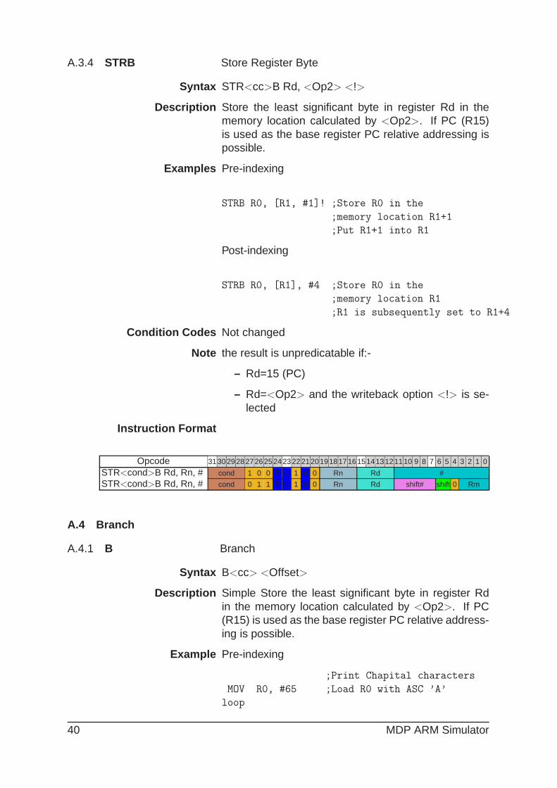
A.3.4 STRB Store Register Byte
Syntax STR<cc>B Rd, <Op2> <!>
Description Store the least significant byte in register Rd in thememory location calculated by <Op2>. If PC (R15)is used as the base register PC relative addressing ispossible.
Examples Pre-indexing
STRB R0, [R1, #1]! ;Store R0 in the
;memory location R1+1
;Put R1+1 into R1
Post-indexing
STRB R0, [R1], #4 ;Store R0 in the
;memory location R1
;R1 is subsequently set to R1+4
Condition Codes Not changed
Note the result is unpredicatable if:-
– Rd=15 (PC)
– Rd=<Op2> and the writeback option <!> is se-lected
Instruction Format
Opcode 31302928272625242322212019181716151413121110 9 8 7 6 5 4 3 2 1 0
STR<cond>B Rd, Rn, # cond 1 0 0 P U 1 W 0 Rn Rd #
STR<cond>B Rd, Rn, # cond 0 1 1 P U 1 W 0 Rn Rd shift# shift 0 Rm
A.4 Branch
A.4.1 B Branch
Syntax B<cc> <Offset>
Description Simple Store the least significant byte in register Rdin the memory location calculated by <Op2>. If PC(R15) is used as the base register PC relative address-ing is possible.
Example Pre-indexing
;Print Chapital characters
MOV R0, #65 ;Load R0 with ASC ’A’
loop
40 MDP ARM Simulator
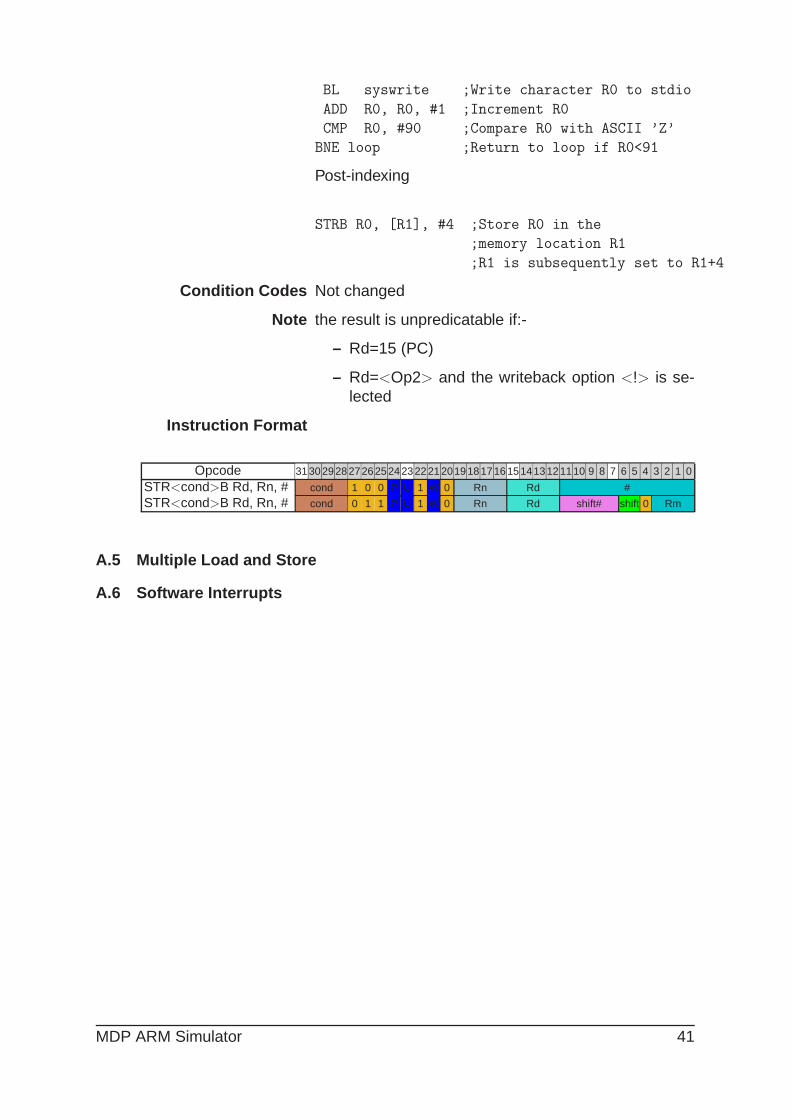
BL syswrite ;Write character R0 to stdio
ADD R0, R0, #1 ;Increment R0
CMP R0, #90 ;Compare R0 with ASCII ’Z’
BNE loop ;Return to loop if R0<91
Post-indexing
STRB R0, [R1], #4 ;Store R0 in the
;memory location R1
;R1 is subsequently set to R1+4
Condition Codes Not changed
Note the result is unpredicatable if:-
– Rd=15 (PC)
– Rd=<Op2> and the writeback option <!> is se-lected
Instruction Format
Opcode 31302928272625242322212019181716151413121110 9 8 7 6 5 4 3 2 1 0
STR<cond>B Rd, Rn, # cond 1 0 0 P U 1 W 0 Rn Rd #
STR<cond>B Rd, Rn, # cond 0 1 1 P U 1 W 0 Rn Rd shift# shift 0 Rm
A.5 Multiple Load and Store
A.6 Software Interrupts
MDP ARM Simulator 41

A.7 Condition Codes
Mnemonic Condition Test Meaning Uses
EQ Z=1 EQual Comparison equal or zero re-sult
NE Z=0 Not Equal Comparison not equal or non-zero result
CS C=1 Carry Set Arithmetic operation gavecarry out
CC C=0 Carry Clear Arithmetic operation did notproduce a carry
HS C=1 Higher or Same Unsigned comparison gavehigher or same result
LO C=0 unsigned LOwer Unsigned comparison gavelower result
MI N=1 MInus Result is minus or negativePL N=0 PLus Result is positive (plus) or
zeroVS V=1 oVerflow Set Signed integer operation:
overflow occurredVC V=0 oVerflow Clear Signed integer operation: no
overflow occurredHI ((NOT C) OR z)=0 Unsigned Higher Unsigned comparison gave
{C set and Z clear}LS ((NOT C) OR Z) =1 unsigned Lower unsigned comparison gave
{C set or Z clear} or Same lower or sameGE (N EOR V) signed Greater than Signed integer comparison
{(N and V) set or or Equal gave greater than or equal(N and V) clear}
LT (N EOR V) =1 signed Less Than Signed integer comparison{(N set and V clear) or gave less than
(N clear and V set)}GT (Z OR (N EOR V))=0 signed Greater Than Signed integer comparison
{((N and V) set or clear) gave greater thanand Z clear}
LE (Z OR (N EOR V)) =1 Less or Equal Signed integer comparison{(N set and V clear) or gave less than or equal
(N clear and V set) or Z set}AL No test Always Always take the branch
42 MDP ARM Simulator

B MAS Rolecks Assembler Subroutines
B.1 System Subroutines
The MAS Rolecks system simulates a number of standardsystem related subroutine calls, similar to those imple-mented in other assemblers. Within MAS Rolecks theycan be called either as SWI’s or as subroutines called witha BL call. It should be noted that to be run on the MDP Mi-crocontroller hardware only the BL method of calling systemsubroutines is supported.
B.1.1 SYS Exit
Terminates the current program
On Entry R1 contains the return code for the program
On Exit This routine does not return
B.1.2 SYS Clock
Returns the number of centiseconds since the executionstarted.
On Entry Register R1 must contain zero. There are no otherparameters.
On Exit R0 contains:
– the number of centiseconds if successful
– -1 if the call is unsuccessful (for example, be-cause of a communications error).
B.1.3 SYS Close
Closes a file on the host system. The handle must referencea file that was opened with SYS Open.
On Entry On entry, r1 contains a pointer to a one-word argumentblock:
word 1 This is a file handle referring to an open file.
On Exit r0 contains:
– 0 if the call is successful
– -1 if the call is not successful.
MDP ARM Simulator 43

B.1.4 SYS Open
Opens a file on the host system.
On Entry R1 contains a pointer to the first byte of the string, con-taining the file name.
On Exit r0 contains:
– 0 if the call is successful
– -1 if the call is not successful.
r1 contains
B.1.5 SYS Read
ToDo: As ADS?
B.1.6 SYS ReadC
Reads a byte from the standard input.
On Entry Register R1 must contain zero. There are no otherparameters or values possible.
On Exit R0 contains the byte read from the console.
B.1.7 SYS WriteC
Writes a character byte, contained in R1, to the standardoutputl.
On Entry R1 contains the character.
On Exit None. Register R0 is corrupted.
Comment This differs from ADS SYS WriteC, where R1 is apointer to the byte.
B.1.8 SYS Write0
Writes a null-terminated string to the standard output.
On Entry R1 contains a pointer to the first byte of the string.
On Exit Register R0 is corrupted.
44 MDP ARM Simulator

B.1.9 SYS Write
Writes the contents of a buffer to a specified file at the cur-rent file position. The file position is specified either:
• explicitly, by a SYS Seek
• implicitly as one byte beyond the previous SYS Reador SYS Write request.
The file position is at the start of the file when the fileis opened, and is lost when the file is closed.
Perform the file operation as a single action wheneverpossible. For example, do not split a write of 16KB intofour 4KB chunks unless there is no alternative.
On Entry R1 contains a pointer to a three-word data block:
– word 1 This contains a handle for a file previouslyopened with SYS Open.
– word 2 This points to the memory containing thedata to be written
– word 3 This contains the number of bytes to bewritten from the buffer to the file.
On Exit R0 contains: 0 if the call is successful the number ofbytes that are not written, if there is an error.
B.1.10 SYS SysCall
Executes a syscall on the host system
On Entry R0 contains the syscall number R1-R7 contain the pa-rameters required by the syscall
On Exit Syscall specific
B.2 High-level Hardware Routines
These routines provide convenient access to the hardware,without exposing implementation details like IC bus ad-dresses. On Rolecks the ’hardware’ implementation is sim-ply graphics in a window.
B.2.1 MAS LED OnOff
Sets LED states to either on or of in a banks of 8 LEDs at atime.
On Entry – R0 contains in bits 0 to 7 the new state of the 8LEDs in the bank indicated by R1
MDP ARM Simulator 45

– R1 contains the LED bank number
On Exit – R0 contains 0 if the operation was successful and-1 otherwise
– R1 is preserved
B.2.2 MAS LED Flash
(optional) Sets LEDs to on, off or flashing states in banks of8 LEDs at a time.
On Entry – R0 contains the LED bank number
– R1 contains in bits 0 to 7 the new state of the 8LEDs in the bank indicated by R0
On Exit – R0 contains 0 if the operation was successful and-1 otherwise
– R1 is preserved
Remarks This routine is intended for use with LEDs connectedto PCA9532 LED dimmers. On implementations withno such devices this routine exits with R0 containing-1.
B.2.3 MAS Motor
(N.B. Note yet implemented) Sets direction and speed ofmotors, 1-4.
On Entry – R0 contains the motor number 0-4
– R1 contains the ’speed’ of the motor. -127 (fullspeed anti-clockwise, 0 stopped, +127 full speedcolckwise)
On Exit – R0 contains 0 if the operation was successful and-1 otherwise
– R1 is preserved
Remarks
B.2.4 MAS IR Read
Reads the current state of the infra-red sensors
On Entry R1 contains the IR bank number (usually 0)
On Exit R0 contains the state of the IR sensors in bits 0..3
46 MDP ARM Simulator

B.2.5 MAS Slider Read
Reads the current state of the analogue slide control
On Entry R1 contains the slider number (usually 0)
On Exit R0 contains the slider value in bits 15..0
Comments On exit R0 will contain a 16-bit number, but it shouldnot be assumed that the ADC that took the reading is16-bit. The lower bits could be 0.
B.2.6 MAS Switch Read
Reads the current state of a bank of up to 8 switches
On Entry R1 contains the switch bank number
On Exit R0 contains the switch settings in bits 7..0
B.3 Mid Level Routines
These routines are convenience wrappers around the theI2C Control or SMBus Control routines, and access hard-ware attached to the MDP Micro-controller.
B.3.1 PCF8574 Read
Reads from a PCF8574 (or PCF8574A) device on the de-fault IC bus.
On Entry R0 contains the 7-bit address of the PCF8574 in bits 0to 6.
On Exit R0 contains:
– the value read from the device in bits 0 to 7;
– -1 if an error occurred.
B.3.2 PCF8574 Write
Writes to a PCF8574 (or PCF8574A) device on the defaultIC bus.
On Entry – R0 contains the 7-bit address of the PCF8574 inbits 0 to 6.
– R1 contains 8 bits of data in bits 0 to 7.
On Exit R0 contains: 0 if the call was sucessful; or -1 if an erroroccurred.
MDP ARM Simulator 47
B.3.3 PCF8591 Configure
This routine configures a PCF8591 4 channel 8-bit ADC(plus 1 channel 8-bit DAC) device on the default IC Bus. Thedevice can be configured with either differential of ? inputson between 2 and 4 channels.
On Entry – R0 contains a reason code
– R1 contains a parameter block
On Exit
B.3.4 PCF8591 ReadADC
B.3.5 PCF8591 WriteDAC
B.3.6 PIC ReadADC
B.3.7 PIC WriteMotor
48 MDP ARM Simulator
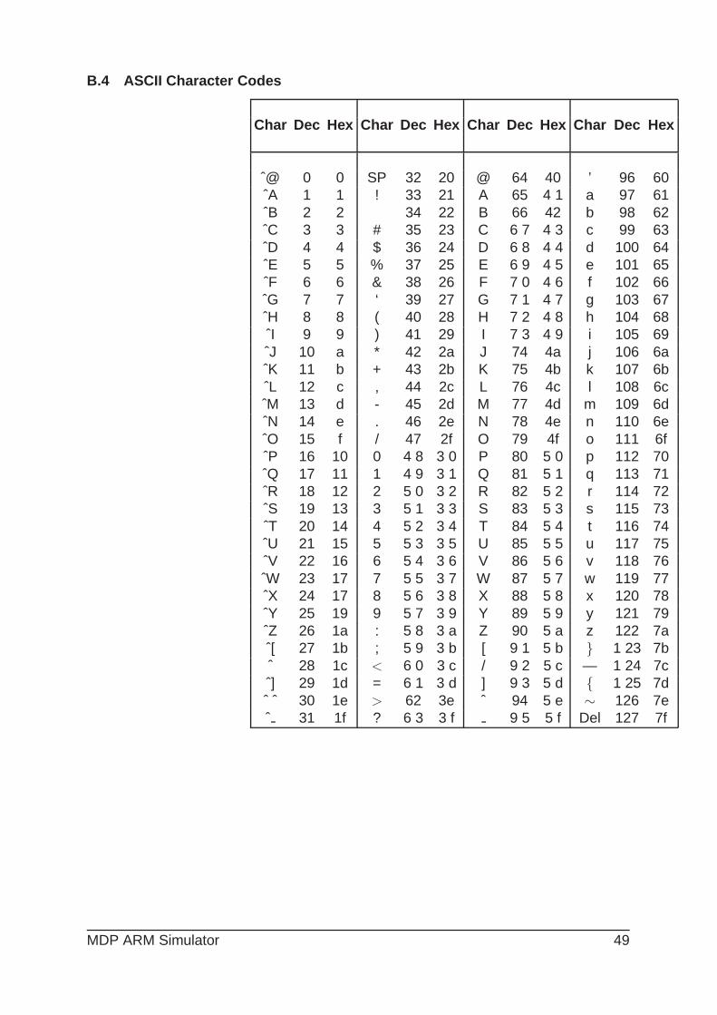
B.4 ASCII Character Codes
Char Dec Hex Char Dec Hex Char Dec Hex Char Dec Hex
ˆ@ 0 0 SP 32 20 @ 64 40 ’ 96 60ˆA 1 1 ! 33 21 A 65 4 1 a 97 61ˆB 2 2 34 22 B 66 42 b 98 62ˆC 3 3 # 35 23 C 6 7 4 3 c 99 63ˆD 4 4 $ 36 24 D 6 8 4 4 d 100 64ˆE 5 5 % 37 25 E 6 9 4 5 e 101 65ˆF 6 6 & 38 26 F 7 0 4 6 f 102 66ˆG 7 7 ‘ 39 27 G 7 1 4 7 g 103 67ˆH 8 8 ( 40 28 H 7 2 4 8 h 104 68ˆI 9 9 ) 41 29 I 7 3 4 9 i 105 69ˆJ 10 a * 42 2a J 74 4a j 106 6aˆK 11 b + 43 2b K 75 4b k 107 6bˆL 12 c , 44 2c L 76 4c l 108 6cˆM 13 d - 45 2d M 77 4d m 109 6dˆN 14 e . 46 2e N 78 4e n 110 6eˆO 15 f / 47 2f O 79 4f o 111 6fˆP 16 10 0 4 8 3 0 P 80 5 0 p 112 70ˆQ 17 11 1 4 9 3 1 Q 81 5 1 q 113 71ˆR 18 12 2 5 0 3 2 R 82 5 2 r 114 72ˆS 19 13 3 5 1 3 3 S 83 5 3 s 115 73ˆT 20 14 4 5 2 3 4 T 84 5 4 t 116 74ˆU 21 15 5 5 3 3 5 U 85 5 5 u 117 75ˆV 22 16 6 5 4 3 6 V 86 5 6 v 118 76ˆW 23 17 7 5 5 3 7 W 87 5 7 w 119 77ˆX 24 17 8 5 6 3 8 X 88 5 8 x 120 78ˆY 25 19 9 5 7 3 9 Y 89 5 9 y 121 79ˆZ 26 1a : 5 8 3 a Z 90 5 a z 122 7aˆ[ 27 1b ; 5 9 3 b [ 9 1 5 b } 1 23 7bˆ 28 1c < 6 0 3 c / 9 2 5 c — 1 24 7cˆ] 29 1d = 6 1 3 d ] 9 3 5 d { 1 25 7dˆ ˆ 30 1e > 62 3e ˆ 94 5 e ∼ 126 7eˆ 31 1f ? 6 3 3 f 9 5 5 f Del 127 7f
MDP ARM Simulator 49