marine fender systems rubber fenders modular fenders...mv-elements are the foundation of many marine...
TRANSCRIPT
Available in a full range of sizes, the geometry of the MV-element has been optimised for maximumenergy absorption per unit volume of rubber combined with a low reaction force. Fully encapsulatedsteel mounting plates are vulcanised inside the MV-element to allow easy fixing. Bolts are locatedcentrally on the base flanges to reduce stresses, but being recessed into pockets the fixings are wellprotected from damage.
The rubber unit is available in several standard lengths and rubber grades which, combined with themodularity of the MI system, provides designers with greater choice and versatility.
Marine Fender SystemsRubber Fenders
Modular Fenders
Modular Fenders 1 / 19SYT_Marine_Systems_01308
www.shinyangtech.com
Contect :
Phone :
Fax :
+82-31-737-2147
+82-31-737-2150
Modular fenders are compression moulded from a high performance polymer designed forlong service life and low maintenance.
MV-elements are the foundation of many marine fender systems. These modular units arecompression moulded from a high performance polymer which resists attack from ultraviolet light,ozone and immersion in seawater for long service life and low maintenance.
The MI-2000 fender systems suit very large vessels and high energy applications. They share themodular design concept with MV elements but with a modified fixing arrangement to allow greaterdeflections and efficiency.
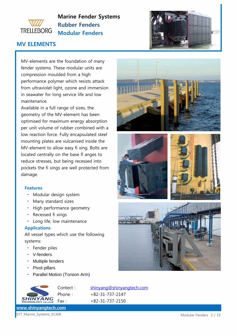
Features
ㆍ Modular design system
ㆍ Many standard sizes
ㆍ High performance geometry
ㆍ Recessed fi xings
ㆍ Long life, low maintenance
Applications
ㆍ Fender piles
ㆍ V-fendersㆍ Multiple fendersㆍ Pivot pillarsㆍ Parallel Motion (Torsion Arm)
Modular Fenders 2 / 19SYT_Marine_Systems_01308
www.shinyangtech.com
Contect :
Phone :
Fax :
+82-31-737-2147
+82-31-737-2150
MV-elements are the foundation of many
fender systems. These modular units are
compression moulded from a high
performance polymer which resists attack
from ultraviolet light, ozone and immersion
in seawater for long service life and low
maintenance.
Available in a full range of sizes, the
geometry of the MV-element has been
optimised for maximum energy absorption
per unit volume of rubber combined with a
low reaction force. Fully encapsulated steel
mounting plates are vulcanised inside the
MV-element to allow easy fi xing. Bolts are
located centrally on the base fl anges to
reduce stresses, but being recessed into
pockets the fi xings are well protected from
damage.
All vessel types which use the following
systems:
Marine Fender SystemsRubber FendersModular Fenders
MV ELEMENTS

Each fender generation
provides more energy for the
same reaction force.
Marine Fender SystemsRubber FendersModular Fenders
MV ELEMENTS
Modular Fenders 3 / 19SYT_Marine_Systems_01308
www.shinyangtech.com
Contect :
Phone :
Fax :
+82-31-737-2147
+82-31-737-2150

Fender Evolution
5th Generation Fenders
Modular Design
Marine Fender SystemsRubber FendersModular Fenders
MV ELEMENTS
Modular Fenders 4 / 19SYT_Marine_Systems_01308
www.shinyangtech.com
Contect :
Phone :
Fax :
+82-31-737-2147
+82-31-737-2150
Ships have grown larger – so have the demands on fenders. A
century ago timber (1st Generation) was cheap and worked
adequately for the small vessels of the day. Old tyres (2nd
Generation) were abundant and softer but required expensive
maintenance and absorbed little energy.
Cylindricals (3rd Generation) were the fi rst purpose designed
fenders, gaining popularity some 50 years ago, but ineffi cient use
of rubber and low performance by today’s standards makes them
costly. Arch and simple buckling fenders (4th Generation) had
better performance and integrated the rubber with steel fixing
plates.
MV-elements are 5th Generation fenders. With refi ned geometry
the rubber has a characteristic double-buckle ‘S’ shape. This gives
the MV-element a greater defl ection for the same reaction so it
absorbs more energy than all previous generations with less
material.
MV-elements are modular so can be installed horizontally or
vertically, close together or further apart, with the ‘V’ facing towards or away from the panel.
‘A’ and ‘B’ compounds can be mixed or different lengths used – allowing almost limitless
permutations and giving the designer greater control on how an MV-system behaves when
impacted.

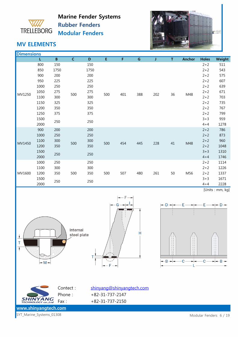
DimensionsL B
Marine Fender SystemsRubber FendersModular Fenders
MV ELEMENTS
SYT_Marine_Systems_01308
Contect :
Phone :
Fax :
+82-31-737-2147
+82-31-737-2150
J T Anchor Holes
4+4
2+2
3+3
5+5
4+4
2+2
250500
WeightC D E F G
2+2 27
900 3+3 41300 94 93 47 17
600M20
54
1500 5+5 68MV300 elements up to 3000mm available on request.1200
50
1000 250 250 2+2 66
750 125 125
99
2000 250 250 4+4 132
1500 250 250
165
3000 250 250 6+6 198
2500 250 250
5+5 278
3000 6+6 334
500 158 142 87 20
2500
250500
250
3+3 167M30
222
1500
2+2 84
1000 2+2 111
M24
MV300
150 300 150
250
3+3 200
750
2+2 153
1500
125 125
M30
M30
2+2 115
100
100 2+2 132
750 125
500250
500 172 170 87 20
MV400 500 550 125 124 63 17
125
750 125 125
1500
2000
225
250
275
2504+4 864
MV5002000
800
100
1500
2000
MV800
750
1000
1500
MV600
MV750
1500
100
MV550250
800
850
900
950
1000
1050
1100
1150
1200
500 500 26 M36 2+2 239
3+3
3+3 230
125 2+2 180
500 188 199 87 20
2+2 214
2+2 268
3+3 402
359
150
250500
150
500250
250 240 129 26 M36
250 250235 230 118
125
4+4 536
150
175
200
500
150
175
200
225
250
275
300
325
350
250
500 322 310 162 31
300
325
350
Modular Fenders 5 / 19
497
2+2 519
3+3 648
M42
2+2 346
2+2 368
2+2 389
2+2 411
2+2 432
2+2 454
2+2 476
2+2
www.shinyangtech.com
MV1000
DimensionsL B
Marine Fender SystemsRubber FendersModular Fenders
MV ELEMENTS
SYT_Marine_Systems_01308
Contect :
Phone :
Fax :
+82-31-737-2147
+82-31-737-2150
J T Anchor Holes
2+2
2+2
2+2
2+2
300
2+2
300
3+3
WeightC D E F G
2+2 511
850 1750 1750 2+2 543
800 150 150
575
950 225 225 2+2 607
900 200 200
639
1050 275 275 2+2 671
1000 250 250
703
1150 325 325 2+2 735
1100 300 300
767
1250 375 375 2+2 799
1200 350 350
250 250
3+3 959
2000
200 200
4+4 1278
1500
1310
2000
250 250
4+4 1746
445 228 41
1500
2+2 960
1200 2+2 1048
1100
350 350
2+2 786
1000
300
873
900
Modular Fenders 6 / 19
MV1250
250
500 500
250
401 388 202 36 M48
MV1450
2+2 1226
www.shinyangtech.com
2000
250
500 500
250
454
3+3 16711500
[Units : mm, kg]
M48
MV1600
250
500 500
250
507 480 261 50 M56
4+4 2228
1200
2+2 1114
1100
350 350 2+2 1337
1000
300

Rated Performance Data (RPD)*
Marine Fender SystemsRubber FendersModular Fenders
MV ELEMENTS
Modular Fenders 7 / 19SYT_Marine_Systems_01308
www.shinyangtech.com
Contect :
Phone :
Fax :
+82-31-737-2147
+82-31-737-2150
LCompound A Compound B
E R E R
MV300
60090012001500
12.6 8.813.217.722.1
649612816031.5
91.4137183229
18.925.2
1000 37.4 203 26.2 142750 26.9 146 18.8 102
3562000 74.8 406 52.3 2841500 56.1 305 39.3 213
28.9 1251000 58.4 254 40.9 178
MV400
MV500
750 41.2 179
1500 87.6 381
3000 112 609 78.5 4272500 93.5 508 65.4
197 34.9
1500 106 419 74.2
61.3 2672000 117 508 81.8 356
293
*Rated Performance Data (RPD)Method: Decreasing Velocity (DV)
Temperature: 23ºC
Initial speed: 150mm/s
Compression angle: 0º
Refer to p2–7.
MV600
750 59.4 215 41.6 1511000 84.1 305 58.9 2131500 126 457
1381000 70.7 279 49.5 196MV550
750 49.9
138 4001000 131 381 92 267
88.3 320750 90.4 262 63.2 183
MV750
MV800
800 111 302
1500 224 609
1500 197 571
157 4272000 299 813 209 569
77.8 2121000 150 406 105 284

All performance values are for a single element.
Marine Fender SystemsRubber FendersModular Fenders
MV ELEMENTS
Modular Fenders 8 / 19SYT_Marine_Systems_01308
www.shinyangtech.com
Contect :
Phone :
Fax :
+82-31-737-2147
+82-31-737-2150
LCompound A Compound B
E R E R
90095010001050
204
219
143
153
164
174
311
333
356
378248
444
476
508
540
234
1150 278 604 195 423
1100 263 572 184 400
1500 350 762 245 533
1200 293 636 205 445
800 269 468 188 327
2000 467 1016 327 711
239 415
1000 365 635 256 444
205 357
900 317 551 222 386
850 293 510
950 341 593
474
1100 413 718 289 503
1050 389 677 272
2000 730 1270 511 889
532
1200 461 802 323 561
1250 485 844 340 591
1500 548 952
1150 437 760 306
MV1000
MV1250
MV1450
516 773
2000 982 1473 688 1031
390 584
1200 622 933 436 653
1100 557 835
1500 737 1105
1000
813 419 569
800 175 380 122 266
850 189 412 133 288
491 736 344 516
900 426 638 298 447
383 667
MV1600
[Units : kNm, kN]2000 1196 1625 837 1138
1500 897 1219 628 853
1200 781 1061 547 743
1100 690 937 483 656
1000 598
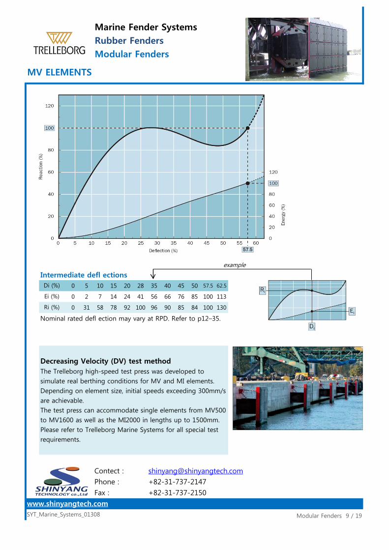
Intermediate defl ections0 5 10 15 20 28 35 40 45 50 57.5 62.5
0 2 7 14 24 41 56 66 76 85 100 113
0 31 58 78 92 100 96 90 85 84 100 130
Nominal rated defl ection may vary at RPD. Refer to p12–35.
Marine Fender SystemsRubber FendersModular Fenders
MV ELEMENTS
Modular Fenders 9 / 19SYT_Marine_Systems_01308
www.shinyangtech.com
Contect :
Phone :
Fax :
+82-31-737-2147
+82-31-737-2150
Di (%)
Ei (%)
Ri (%)
example
Decreasing Velocity (DV) test methodThe Trelleborg high-speed test press was developed to
simulate real berthing conditions for MV and MI elements.
Depending on element size, initial speeds exceeding 300mm/s
are achievable.
The test press can accommodate single elements from MV500
to MV1600 as well as the MI2000 in lengths up to 1500mm.
Please refer to Trelleborg Marine Systems for all special test
requirements.
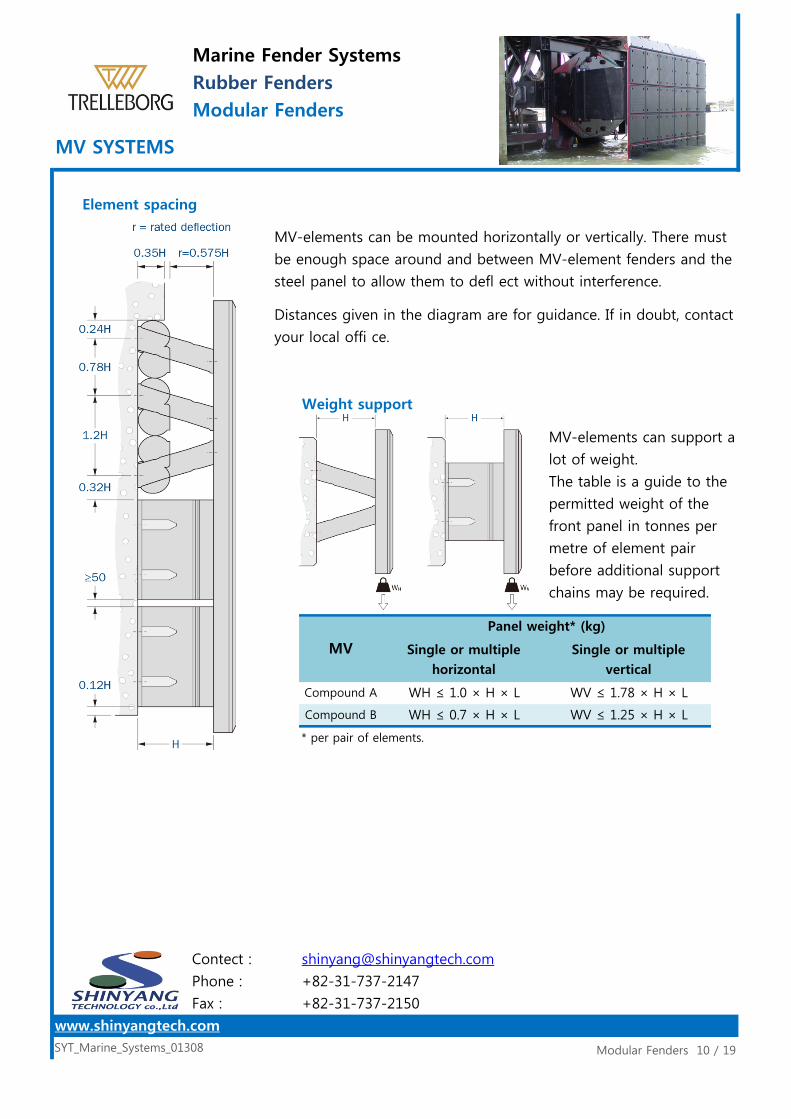
Element spacing
Weight support
* per pair of elements.
Compound B
Single or multiplehorizontal
Single or multiplevertical
Panel weight* (kg)
WH ≤ 1.0 × H × L
WH ≤ 0.7 × H × L
WV ≤ 1.78 × H × L
WV ≤ 1.25 × H × L
Marine Fender SystemsRubber FendersModular Fenders
MV SYSTEMS
Modular Fenders 10 / 19SYT_Marine_Systems_01308
www.shinyangtech.com
Contect :
Phone :
Fax :
+82-31-737-2147
+82-31-737-2150
MV-elements can be mounted horizontally or vertically. There must
be enough space around and between MV-element fenders and the
steel panel to allow them to defl ect without interference.
Distances given in the diagram are for guidance. If in doubt, contact
your local offi ce.
MV-elements can support a
lot of weight.
The table is a guide to the
permitted weight of the
front panel in tonnes per
metre of element pair
before additional support
chains may be required.
MV
Compound A

Shear stiffness
DL ≈ 0.39 × μ × H
DT ≈ 0.82 × μ × H
Where,
H = fender height
μ = friction coeffi cient
Tension
Some temporary shear may be caused by friction as the
MV-elements are compressed.
Maximum shear usually occurs at approximately 28% defl
ection.
If the likely tensile load exceeds the rated reaction then tension
chains may be required. Please refer to your local office.
Marine Fender SystemsRubber FendersModular Fenders
MV SYSTEMS
Modular Fenders 11 / 19SYT_Marine_Systems_01308
www.shinyangtech.com
Contect :
Phone :
Fax :
+82-31-737-2147
+82-31-737-2150
Marine Fender SystemsRubber FendersModular Fenders
MV SYSTEMS
Modular Fenders 12 / 19SYT_Marine_Systems_01308
www.shinyangtech.com
Contect :
Phone :
Fax :
+82-31-737-2147
+82-31-737-2150
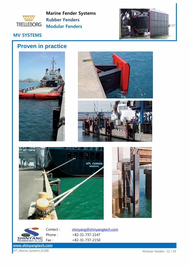
Proven in practice
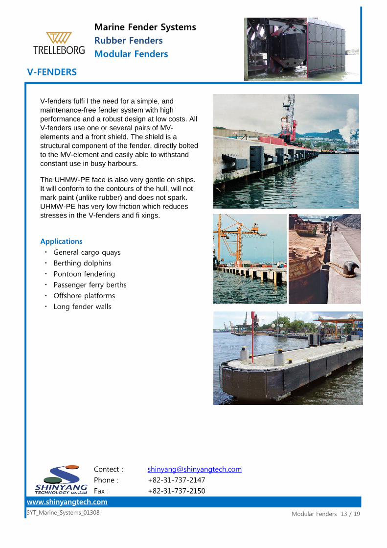
Applications
ㆍ General cargo quays
ㆍ Berthing dolphins
ㆍ Pontoon fendering
ㆍ Passenger ferry berths
ㆍ Offshore platforms
ㆍ Long fender walls
The UHMW-PE face is also very gentle on ships.It will conform to the contours of the hull, will notmark paint (unlike rubber) and does not spark.UHMW-PE has very low friction which reducesstresses in the V-fenders and fi xings.
Marine Fender SystemsRubber FendersModular Fenders
V-FENDERS
Modular Fenders 13 / 19SYT_Marine_Systems_01308
www.shinyangtech.com
Contect :
Phone :
Fax :
+82-31-737-2147
+82-31-737-2150
V-fenders fulfi l the need for a simple, andmaintenance-free fender system with highperformance and a robust design at low costs. AllV-fenders use one or several pairs of MV-elements and a front shield. The shield is astructural component of the fender, directly boltedto the MV-element and easily able to withstandconstant use in busy harbours.
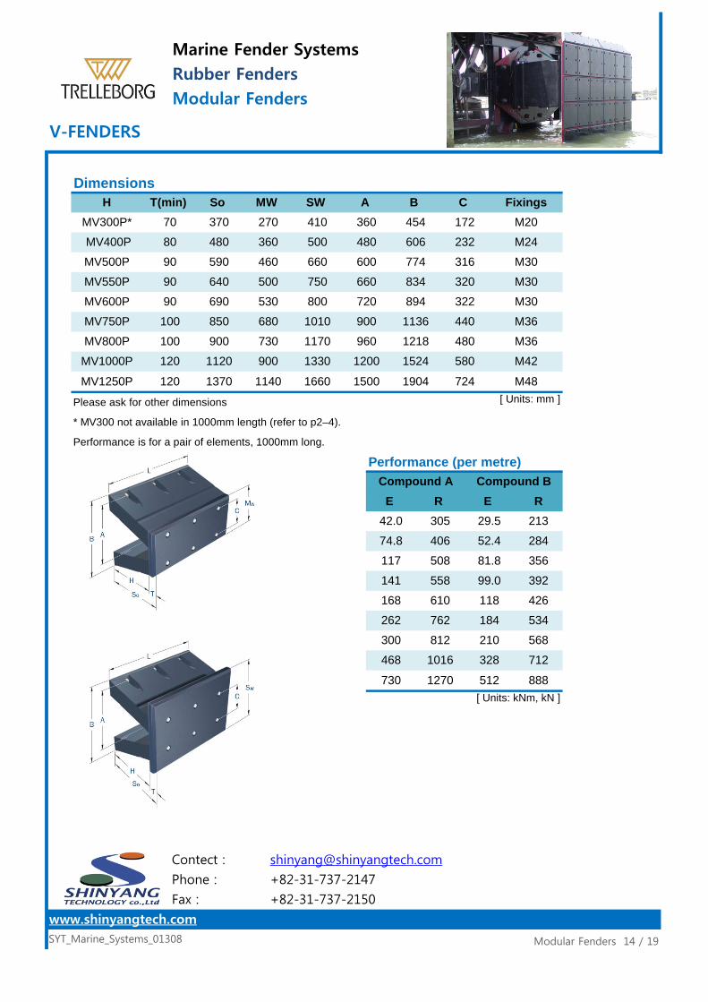
Dimensions
Please ask for other dimensions
* MV300 not available in 1000mm length (refer to p2–4).
Performance is for a pair of elements, 1000mm long.
Performance (per metre)
Marine Fender SystemsRubber FendersModular Fenders
V-FENDERS
Modular Fenders 14 / 19SYT_Marine_Systems_01308
www.shinyangtech.com
Contect :
Phone :
Fax :
+82-31-737-2147
+82-31-737-2150
H MV300P* 410 360 454 172 M20
SW A B C Fixings
M2490 590 460 660 600 774 316 M3080 480 360 500
T(min) 70 370
So MW 270
MV550P 90 640 500 750MV600P
480 606 232MV400P
660 834 320 M3090 690 530 800 720 894 322 M30
100 900 730 1170 960 1218 480 M36MV750P 100 850 680 1010MV800P
[ Units: mm ]
MV500P
1200 1524 580 M42
120 1370 1140 1660 1500 1904 724 M48
MV1000P 120 1120 900 1330
MV1250P
900 1136 440 M36
42.0 305 29.5 21374.8 406 52.4 284
Compound A Compound BE R E R
168 610 118 426262 762 184 534
117 508 81.8 356141 558 99.0 392
730 1270 512 888[ Units: kNm, kN ]
300 812 210 568468 1016 328 712
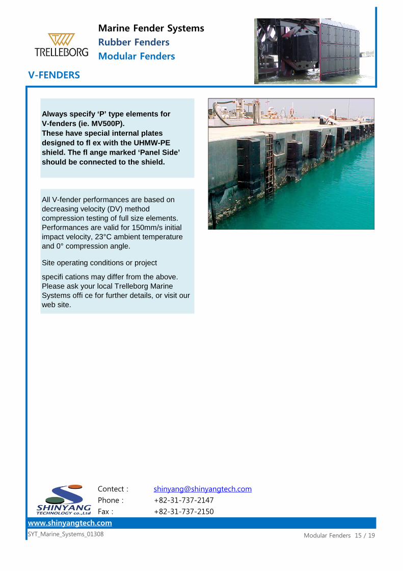
Site operating conditions or project
Modular Fenders 15 / 19SYT_Marine_Systems_01308
www.shinyangtech.com
Contect :
Phone :
Fax :
+82-31-737-2147
+82-31-737-2150
Always specify ‘P’ type elements forV-fenders (ie. MV500P).These have special internal platesdesigned to fl ex with the UHMW-PEshield. The fl ange marked ‘Panel Side’should be connected to the shield.
All V-fender performances are based ondecreasing velocity (DV) methodcompression testing of full size elements.Performances are valid for 150mm/s initialimpact velocity, 23°C ambient temperatureand 0° compression angle.
specifi cations may differ from the above.Please ask your local Trelleborg MarineSystems offi ce for further details, or visit ourweb site.
Marine Fender SystemsRubber FendersModular Fenders
V-FENDERS

Featuresㆍ Modular design systemㆍ Choice of lengths and rubber gradesㆍ High performance and effi ciencyㆍ Long life, low maintenance
ApplicationsIdeal for larger vessels including:ㆍ Tankers and LNG shipsㆍ Bulk carriersㆍ Post-Panamax containersㆍ Mega cruise ships
MI-2000 fender systems suit very largevessels and high energy applications.They share the modular design conceptwith MV elements but with a modifi ed fixing arrangement to allow greaterdeflections and effi ciency.
The rubber unit is available in severalstandard lengths and rubber gradeswhich, combined with the modularity ofthe MI system, provides designers withgreater choice and versatility.
Marine Fender SystemsRubber FendersModular Fenders
MI-2000 ELEMENTS
Modular Fenders 16 / 19SYT_Marine_Systems_01308
www.shinyangtech.com
Contect :
Phone :
Fax :
+82-31-737-2147
+82-31-737-2150

MI-2000 Dimensions
MI-2000S Dimensions
Modular Fenders 17 / 19SYT_Marine_Systems_01308
www.shinyangtech.com
Contect :
Phone :
Fax :
+82-31-737-2147
+82-31-737-2150
6+6 1840Holes WeightC Anchor
1130 M42
Marine Fender SystemsRubber FendersModular Fenders
MI-2000 ELEMENTS
A B 1000 1270
6+6
1330 M42 1200 6+6 2245
1180 M42 6+6 19411050 13201100 1370
15201470
1230 M42 6+6 20421150 1420 1280 M42 6+6 2144
1380 M42 1250 6+6 2346
[ Units: mm, kg ]
A B C Anchor Holes Weight*
24471350 1620 1480 M42 6+6 2549
1530 M42 6+6 265016701400
1300 1570 1430 M42
21911050 1320 1180 M42 6+6 22861000 1270 1130 M42 6+6
23831150 1420 1280 M42 6+6 24801100 1370 1230 M42 6+6
25731250 1520 1380 M42 6+6 26701200 1470 1330 M42 6+6
2957[ Units: mm, kg ]
* MI-2000S weight includes fabricated spacers forboth fl anges (supplied with fender elements onrequest).
1400 1670 1530 M42 6+6
27651350 1620 1480 M42 6+6 28601300 1570 1430 M42 6+6

ER
RR
ER
RR
ER
RR
ER
RR
ER
RR
ER
RR
ER
RR
ER
RR
ER
RR
All values are for
a single element.
Intermediate defl ections0 5 10 15 20 25 30 35 40 45 50 55 60 62 65
0 2 6 14 23 32 42 52 61 71 79 88 96 100 103
0 34 63 84 95 99 100 98 95 91 86 82 90 100 127
Nominal rated defl ection may vary at RPD. Refer to p12–35.
All MI-2000 performance values are based on decreasingvelocity (DV) method compression testing of full size elementson a dedicated high speed test press. Performances are valid for150mm/s initial impact velocity, 23°C ambient temperature and0° compression angle.Site operating conditions or project specifi cations may differfrom the above. Please ask your local Trelleborg MarineSystems offi ce for further details, or visit our web site.
MI-2000 Performance
791[ Units: kN, kNm ]
Di (%)
Ei (%)
Ri (%)
example
7631248 7631295 791
1156 7061202 7341202 734
1110 6781110 6781156 706
1017 6211063 6501063 650
971 593971 593
1017 6211100
1150
1200
1250
1300
A Compound A Compound B
1000925925
565565
Marine Fender SystemsRubber FendersModular Fenders
MI-2000
Modular Fenders 18 / 19SYT_Marine_Systems_01308
www.shinyangtech.com
Contect :
Phone :
Fax :
+82-31-737-2147
+82-31-737-2150
1050
14001295
13501248

ER
RR
ER
RR
ER
RR
ER
RR
ER
RR
ER
RR
ER
RR
ER
RR
ER
RR
All values are for
a single element.
Intermediate defl ections0 5 10 15 20 25 30 35 40 45 50 55 60 66 67.5
0 2 6 13 21 30 40 49 58 67 75 82 90 100 103
0 35 63 83 95 99 100 98 94 90 85 81 81 100 110
Nominal rated defl ection may vary at RPD. Refer to p12–35.
Marine Fender SystemsRubber FendersModular Fenders
MI-2000S
Modular Fenders 19 / 19SYT_Marine_Systems_01308
www.shinyangtech.com
Contect :
Phone :
Fax :
+82-31-737-2147
+82-31-737-2150
1050
14001295
13501336
A Compound A Compound B
1000989925
604565
1100
1150
1200
1250
1300
1039 635971 593
1088 6651017 6211138 6951063 650
7861202 734
1187 7251110 6781237 756
All MI-2000S performance values are based on decreasingvelocity (DV) method compression testing of full size elementson a dedicated high speed test press. Performances are valid for150mm/s initial impact velocity, 23°C ambient temperature and0° compression angle.Site operating conditions or project specifi cations may differfrom the above. Please ask your local Trelleborg MarineSystems offi ce for further details, or visit our web site.
MI-2000S Performance
791[ Units: kN, kNm ]
Di (%)
Ei (%)
Ri (%)
example
8161248 7631385 846
1156 7061286