mapleson system
TRANSCRIPT

MAPLESON SYSTEM
Dr. Padmaja Pallavi Pandey
ERA’s Lucknow Medical College & Hospital
2014 Batch

CONTENTS
History of Breathing System Characteristics Classification Components Lacks Mapleson A System Configurations Classic form Lack Modification
CONTENTS
Techniques of Use Functional Analysis Spontaneous Respiration Controlled or Assisted Ventilation Hazards Preuse Checks Mapleson B System Techniques of Use
CONTENTS
Functional Analysis Spontaneous Respiration Controlled or Assisted Ventilation Mapleson C System Techniques of Use Functional Analysis Mapleson D System Configurations Classic form

CONTENTS
Bain Modification Techniques of Use Functional Analysis Spontaneous Breathing Controlled Ventilation Bain System Hazards Preuse Checks Continuous Positive Airway Pressure

CONTENTS
Mapleson E System Techniques of Use Functional Analysis Rebreathing Air Dilution Hazards Mapleson F System Techniques of Use Functional Analysis

CONTENTS
Hazards Respiratory Gas Monitoring with the Mapleson
Systems Advantages of the Mapleson Systems Disadvantages of the Mapleson System

“NECESSITY IS MOTHER OF INVENTION”
Earlier circuits were simple, differing in the type of anesthetic agent administered.
The purpose of breathing systems that have evolved in anesthetic practice is to deliver Gas & Vapor to the patient in an appropriate, controlled & efficient manner.
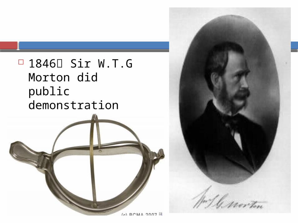
1846 Sir W.T.G Morton did public demonstration with Ether.

1876 Clover`s Inhaler developed by J.T Clover.

1907 Barth used it to administer N₂O.
1909 Teter`s apparatus developed.
1909-13 F.W.Hewitts developed Hewitt`s apparatus.
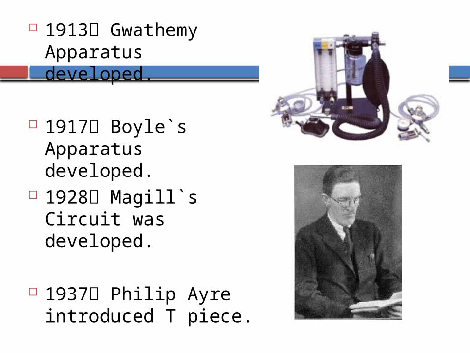
1913 Gwathemy Apparatus developed.
1917 Boyle`s Apparatus developed.
1928 Magill`s Circuit was developed.
1937 Philip Ayre introduced T piece.
HISTORY
1972 J.A Bain & W.E Spoerel introduced Bain`s Circuit.
1975 Dr Gordon Jackson Rees developed Mapleson F system.
Humphrey Davy, Brock & Downing developed combined ADE system.

History
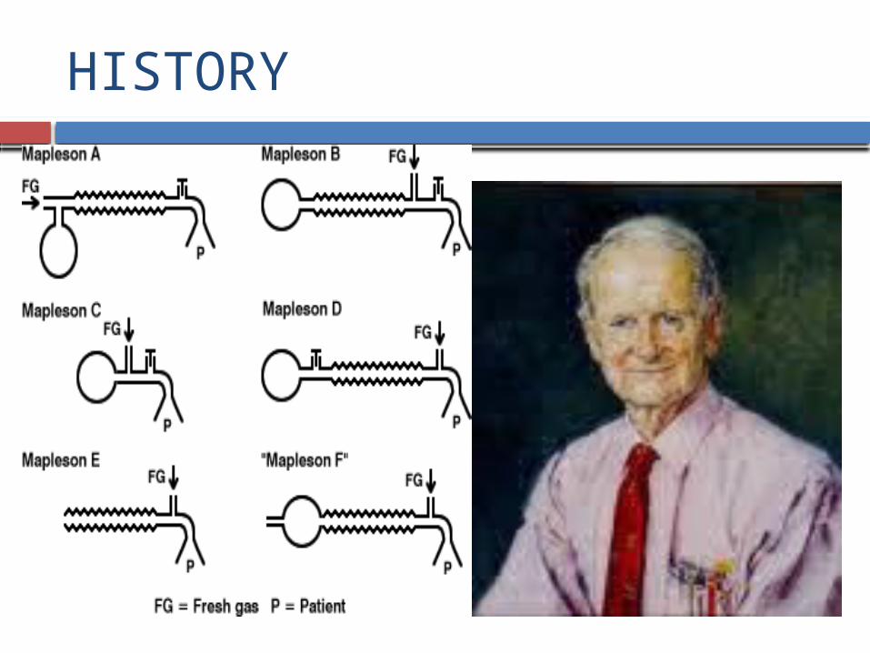
In 1954, Prof. WW Mapleson from University of Wales, Cardiff, classified the several breathing systems around depending on what components they contained and what position they took in the system,Analyzed Five different anaesthetic breathing systems & referred as Mapleson A – E.
In 1975 Willis et al described F system & added to above.
In 1976 – Lack circuit .
HISTORY

.
.
CHARACTERISTICS
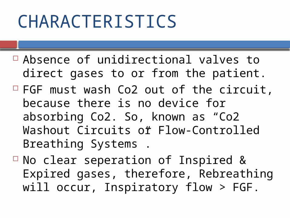
Absence of unidirectional valves to direct gases to or from the patient.
FGF must wash Co2 out of the circuit, because there is no device for absorbing Co2. So, known as “Co2 Washout Circuits or Flow-Controlled Breathing Systems”.
No clear seperation of Inspired & Expired gases, therefore, Rebreathing will occur, Inspiratory flow > FGF.

CHARACTERISTICS Composition of the inspired mixture will depend on
how much Rebreathing takes place.
Monitoring End-Tidal Carbon-Dioxide is the best method to determine the optimal FGF.
With Rebreathing , arterial Carbon-Dioxide to End-Tidal Carbon-Dioxide gradient decreases.

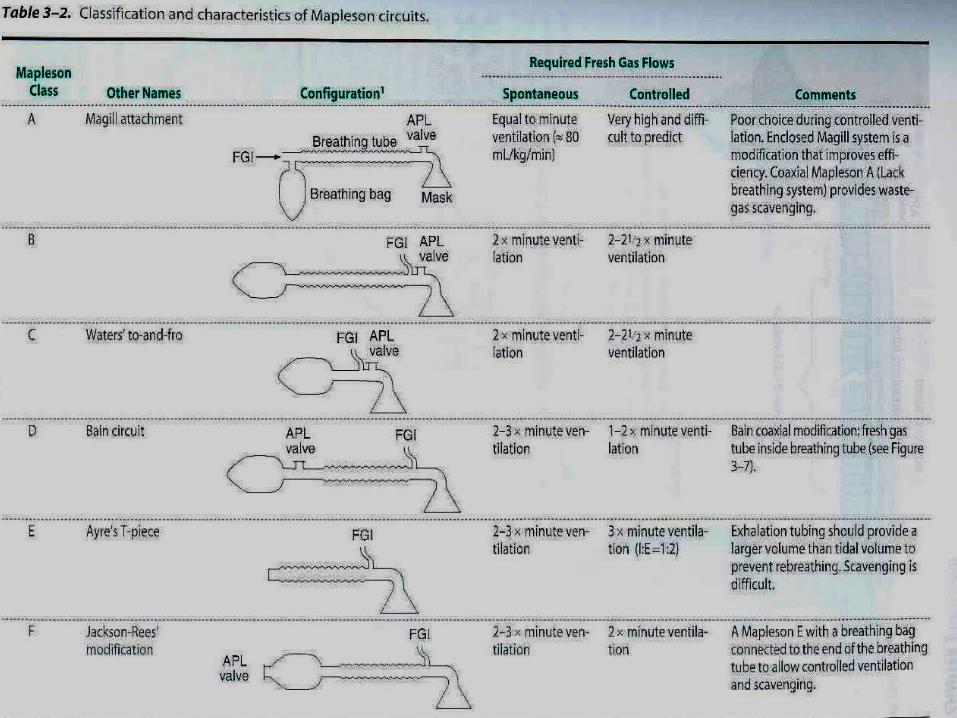
CLASSIFICATION
Six types :- Mapleson A – Magill & Lack System Mapleson B Mapleson C Bagging System Mapleson D or Bain System Mapleson E Mapleson F or Jackson-Rees modification of the T-
Piece


COMPONENTS
Reservoir Bag Corrugated Tubing APL Valve Fresh gas inlet Patient Connection

LACKS
Carbon-Dioxide absorbers Unidirectional Valves Separate Inspiratory & Expiratory limbs.

For better understanding of functional analysis they have been classified as -
1) Afferent Reservoir System (ARS)
2) Enclosed Afferent Reservoir System
3) Efferent Reservoir System
4) Combined System
The efficiency of a system is determined in terms of CO₂ elimination & FGF utilization.

• Afferent limb is that part of the breathing system which delivers the fresh gas from the machine to the patient.
• If the reservoir is placed in this limb as in Mapleson A, B, C and Lack’s systems they are called as afferent reservoir system.
• Efferent limb is that part of the breathing system which carries the expired gas from the patient and vents it to the atmosphere through the expiratory valve/port.
• If the reservoir is placed in this limb as in Mapleson D, E, F and Bain systems they are called efferent reservoir system

Mapleson postulates (1954)
Mapleson has analyzed these bi-directional flow systems & few basic assumptions have been made which are of historical interest.
Gases move En-bloc i.e they maintain their identity as fresh gas, dead space gas & alveolar gas. There is no mixing of these gases.
• Reservoir bags continues to fill up, without offering any resistance till it is full.
• The expiratory valve opens as soon as the reservoir bag is full & pressure inside the system goes above the atmospheric pressure.
• The valve remains open throughout the expiratory phase without offering any resistance to gas flow & closes at the start of next inspiration.

MAPLESON A SYSTEM
• Originally described by Evan Magill.
• Length of breathing tube 110-180 cms.
• FGF from machine end.• APL close to patient.• Sampling ports to be
placed between APL valve & the tube.
MAPLESON A SYSTEM
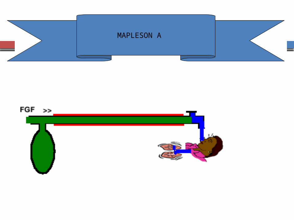
CONFIGURATIONS :-
1) CLASSIC FORM – Also k/a Magill attachment or system Fresh gas does not enter the system near the patient
connection but enters at the other end of the system near the reservoir bag.
A corrugated tubing connects the bag to the adjustable pressure limiting(APL) Valve at the patient end of the system.
MAPLESON A

MAPLESON A SYSTEM
MAPLESON A SYSTEM
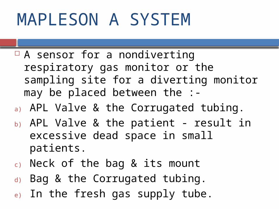
A sensor for a nondiverting respiratory gas monitor or the sampling site for a diverting monitor may be placed between the :-
a) APL Valve & the Corrugated tubing.
b) APL Valve & the patient - result in excessive dead space in small patients.
c) Neck of the bag & its mount
d) Bag & the Corrugated tubing.
e) In the fresh gas supply tube.

MAPLESON A SYSTEM
2) LACK MODIFICATION – Has an added “Expiratory” Limb, which runs from the
patient connection to the APL Valve at the machine end of the system, makes it easier to adjust the valve & facilitates scavenging excess gases, increases the work of breathing slightly.
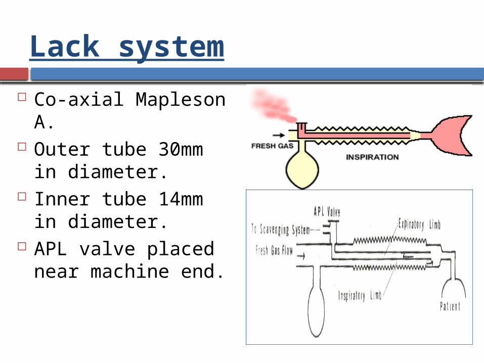
Available in both- Dual (Parallel) tube arrangement Tube-Within-a-tube (Coaxial) Configuration, the
Expiratory limb runs concentrically inside the outer inspiratory limb.
Lack system
Co-axial Mapleson A. Outer tube 30mm in
diameter. Inner tube 14mm in
diameter. APL valve placed near
machine end.
Function

LACK’S MODIFICATION

MAPLESON A (LACK) SYSTEM
MAPLESON A SYSTEM
TECHNIQUES OF USE :-
SPONTANEOUS VENTILATION – APL Valve is kept in the fully open position. During late phase of exhalation, excess gas exits
through it.
MAPLESON A SYSTEM
CONTROLLED OR ASSISTED VENTILATION – Intermittent positive pressure is applied to the bag. The APL Valve is partially closed so that when the bag
is squeezed, sufficient pressure to inflate the lungs is achieved.
The APL Valve opens during inspiration.

MAPLESON A SYSTEM
FUNCTIONAL ANALYSIS :-
1) SPONTANEOUS RESPIRATION – Patient exhales- First “Dead Space Gas” & then “Alveolar Gases” flow
into the Corrugated tubing toward the bag “Fresh Gas” flows into the bag. Bag is full , pressure in the system rises until the APL
Valve opens. First gas vented will be “Alveolar Gas”.
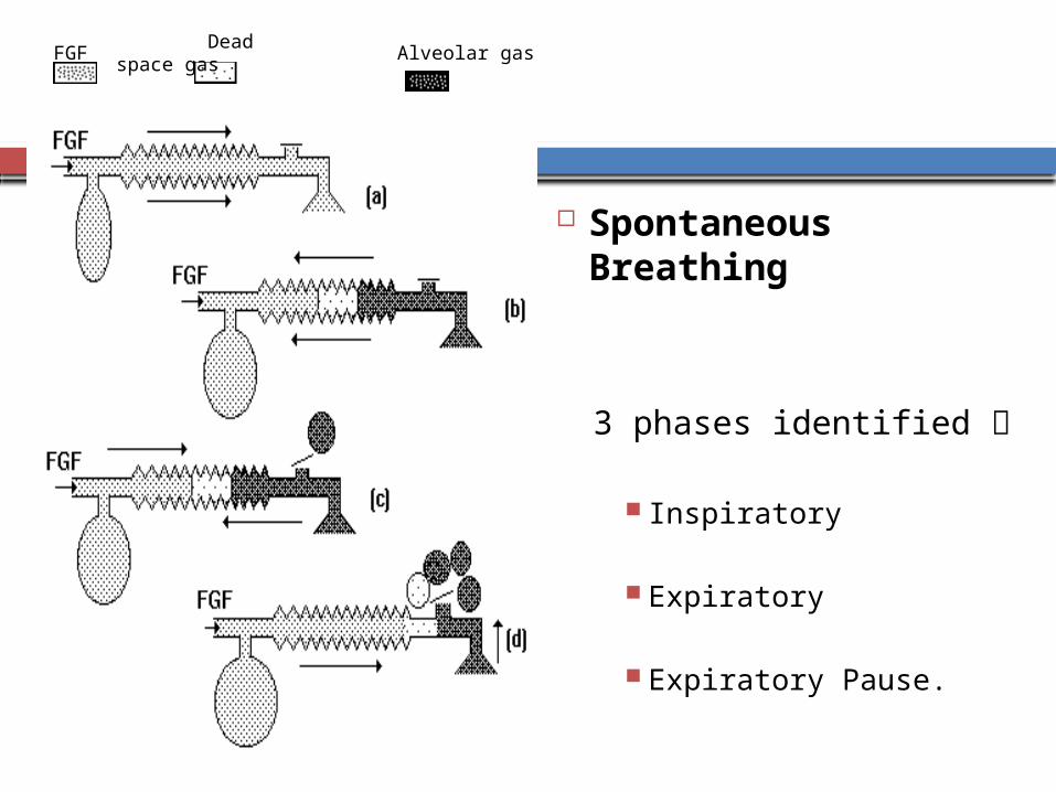
Spontaneous Breathing
3 phases identified
Inspiratory Expiratory
Expiratory Pause.
FGF Dead space gas
Alveolar gas
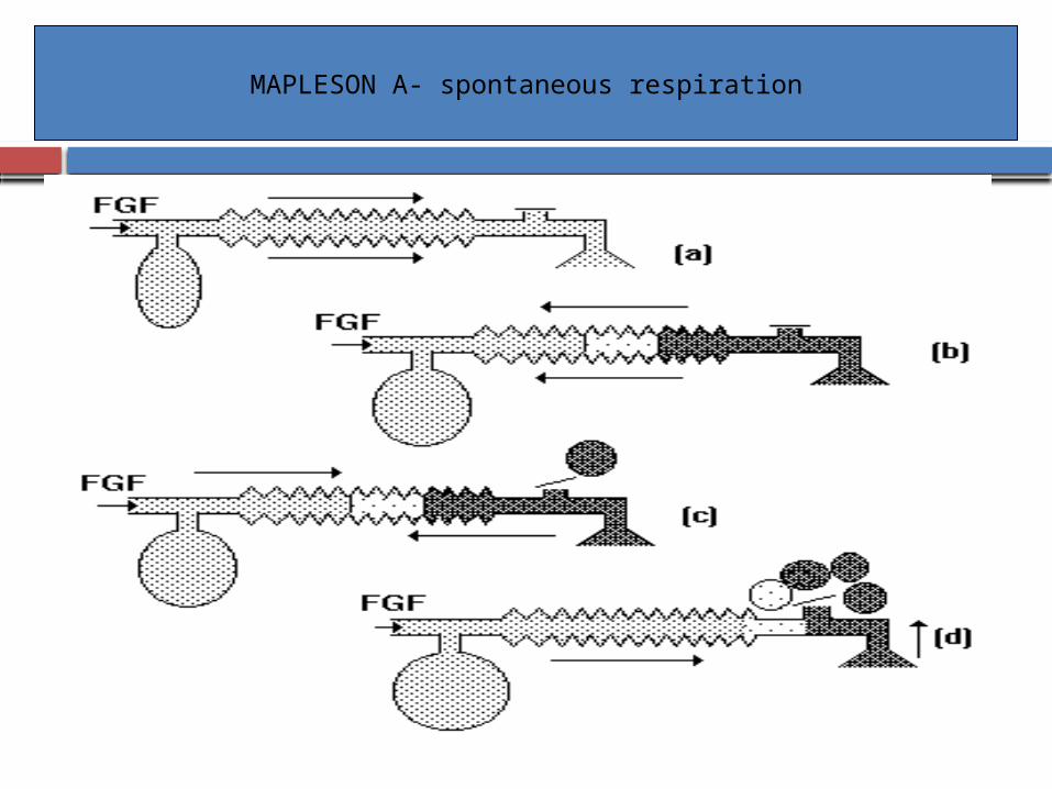
MAPLESON A- spontaneous respiration

MAPLESON A SYSTEM
Remainder of exhalation i.e. only “Alveolar Gas”, exhausts through the open APL Valve.
In the Corrugated tubing, the continuing inflow of “Fresh Gas” reverses the flow of exhaled gases.
Some alveolar gas that bypassed the APL Valve, returns back & exits through it.
FGF is :-
High –Force the dead space gas out.
Intermediate –Some dead space gas will be retained in the system.
Low –More alveolar gas will be retained.
MAPLESON A SYSTEM
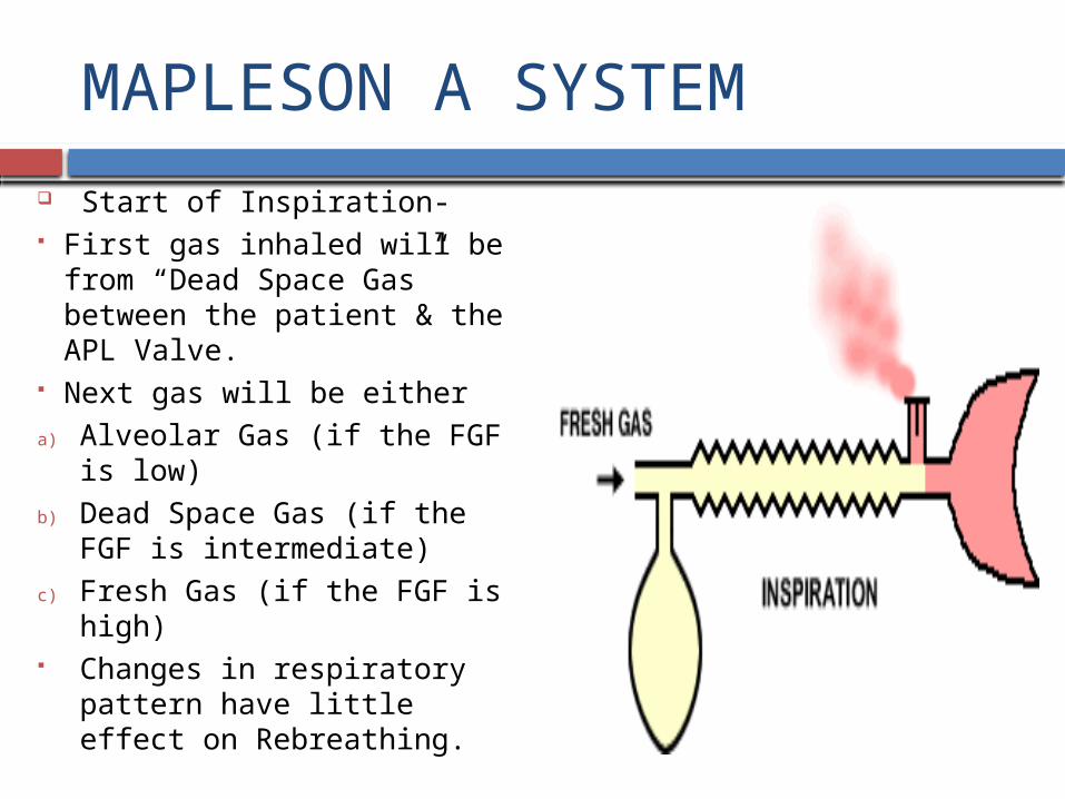
Start of Inspiration- First gas inhaled will be from
“Dead Space Gas” between the patient & the APL Valve.
Next gas will be either
a) Alveolar Gas (if the FGF is low)
b) Dead Space Gas (if the FGF is intermediate)
c) Fresh Gas (if the FGF is high) Changes in respiratory pattern
have little effect on Rebreathing.

MAPLESON A SYSTEM
Rebreathing begins when the FGF is reduced to 56-82 ml/kg/min or 58% - 83% of minute volume.
FGF to 51-85 ml/kg/min & 42% - 88% of minute volume have been recommended to avoid rebreathing.
. .
.

MAPLESON A SPONTANEOUS

MAPLESON A SYSTEM
2) CONTROLLED OR ASSISTED VENTILATION – The pattern of gas flow changes. Exhalation- Pressure in the system will remain low No gas will escape through the APL Valve, unless the
bag becomes distended. Exhaled gases i.e. both “Dead Space Gas” & “Alveolar
Gas” remain in the Corrugated tubing. “Alveolar Gas” is nearest to the patient.

MAPLESON A- controlled ventilation
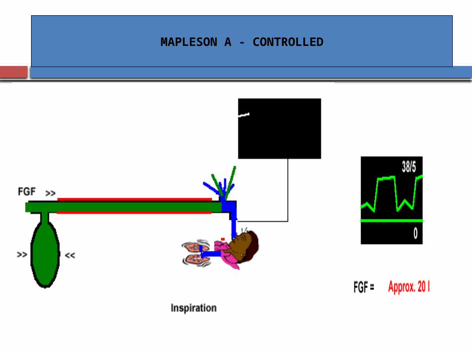
MAPLESON A - CONTROLLED
MAPLESON A SYSTEM
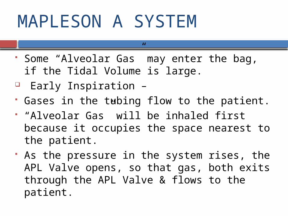
Some “Alveolar Gas” may enter the bag, if the Tidal Volume is large.
Early Inspiration – Gases in the tubing flow to the patient. “Alveolar Gas” will be inhaled first because it
occupies the space nearest to the patient. As the pressure in the system rises, the APL Valve
opens, so that gas, both exits through the APL Valve & flows to the patient.
MAPLESON A SYSTEM
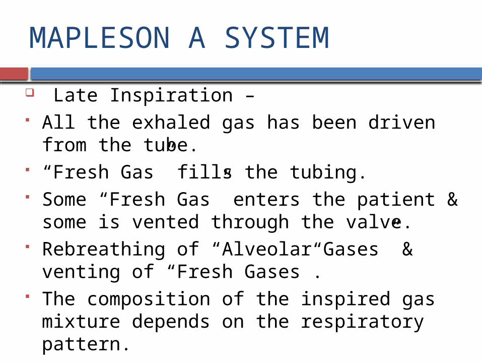
Late Inspiration – All the exhaled gas has been driven from the tube. “Fresh Gas” fills the tubing. Some “Fresh Gas” enters the patient & some is vented
through the valve. Rebreathing of “Alveolar Gases” & venting of “Fresh
Gases”. The composition of the inspired gas mixture depends
on the respiratory pattern.

MAPLESON A SYSTEM
As the expiratory phase is prolonged, system becomes more efficient.
During Inspiration, if the APL Valve does not vent gas, the Mapleson A System can be as efficient as the Mapleson D System.
During Assisted Ventilation, it is less efficient than
with Spontaneous Ventilation but is more efficient than with Controlled Ventilation.

MAPLESON A SYSTEM
HAZARDS :-
A Mechanical Ventilator that vents excess gases should not be used because the entire system then becomes “Dead Space”.

TESTING FOR LEAKS/MAGILL
PREUSE CHECKS :- Tested for leaks by occluding the patient end of the
system, closing the APL Valve & pressurizing the system.
Opening the APL Valve will confirm proper functioning of that component.
The user or a patient should breathe through the system.
TESTING FOR LEAKS/LACK
The coaxial lack system requires additional testing to confirm the integrity of the inner tube –
A) To attach a tracheal tube to the inner tubing at the patient end of the system. Blowing down the tube with the APL Valve closed will produce movement of the bag, if there is a leak between the two limbs.
B) To occlude both limbs at the patient connection with the APL Valve open & then squeeze the bag. Leak in the inner limb, gas will escape through the APL Valve & the bag will collapse.
MAPLESON B SYSTEM
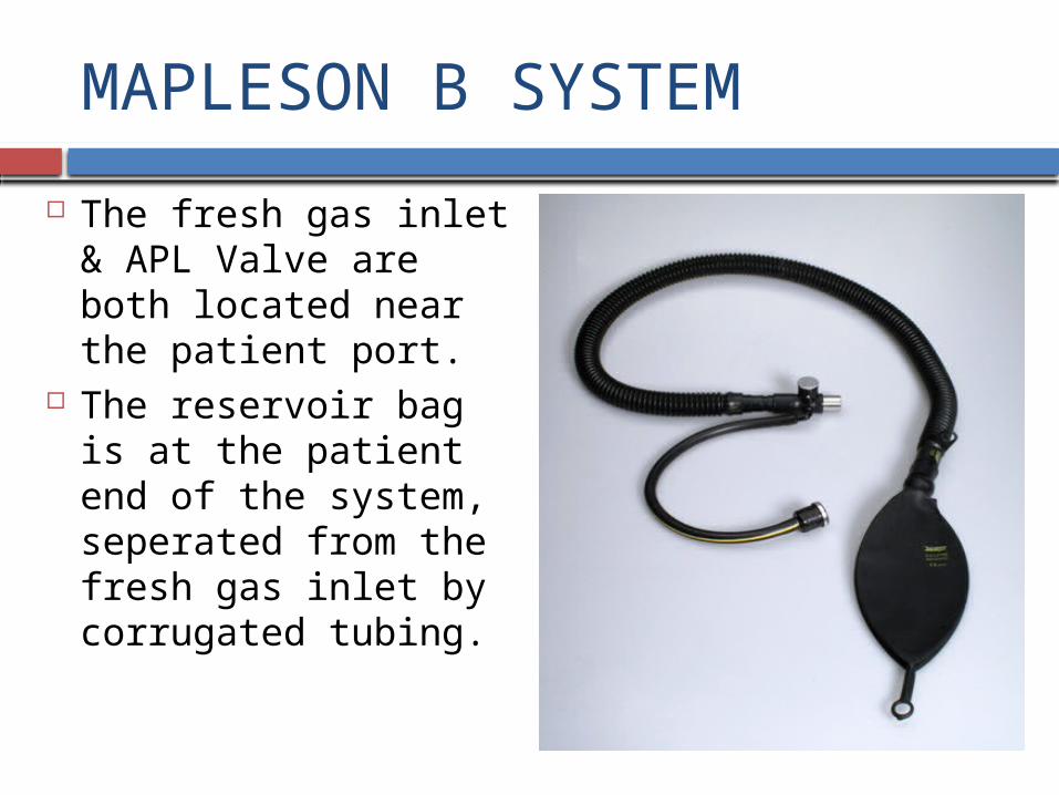
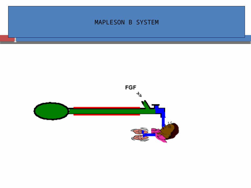
The fresh gas inlet & APL Valve are both located near the patient port.
The reservoir bag is at the patient end of the system, seperated from the fresh gas inlet by corrugated tubing.
MAPLESON B SYSTEM

MAPLESON B SYSTEM
FUNCTIONAL ANALYSIS :-
1) SPONTANEOUS RESPIRATION – Exhalation “Dead Space Gas” will pass down the corrugated
tubing, along with “Fresh Gas”. The tubing near the patient will be filled with “Fresh
Gas” & some “Alveolar Gas”. When the bag reaches full capacity, the APL Valve
opens & both “Fresh Gas” and “Alveolar Gas” will exit from the system.
MAPLESON B SYSTEM
Inspiration – The APL Valve closes The patient inhales “Fresh Gas” and gas from the
tubing. No gas will be inhaled from the bag, if the volume of
the tubing exceeds the tidal volume. To avoid Rebreathing, the FGF must be equal to peak
inspiratory flow rate (normally 20-25l/min)
MAPLESON B SYSTEM
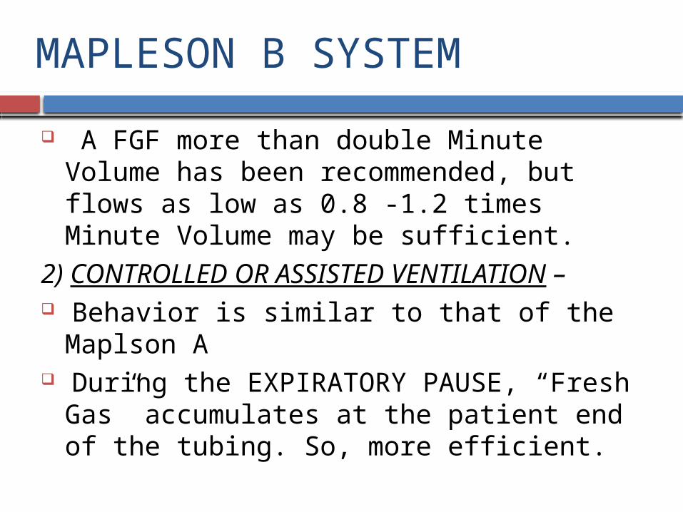
A FGF more than double Minute Volume has been recommended, but flows as low as 0.8 -1.2 times Minute Volume may be sufficient.
2) CONTROLLED OR ASSISTED VENTILATION – Behavior is similar to that of the Maplson A During the EXPIRATORY PAUSE, “Fresh Gas”
accumulates at the patient end of the tubing. So, more efficient.

MAPLESON B SYSTEM
The composition of the inspired gas is influenced by the ventilatory pattern
Has variable performance.
A FGF of 2-2.5 times Minute Volume has been recommended.
MAPLESON C SYSTEM
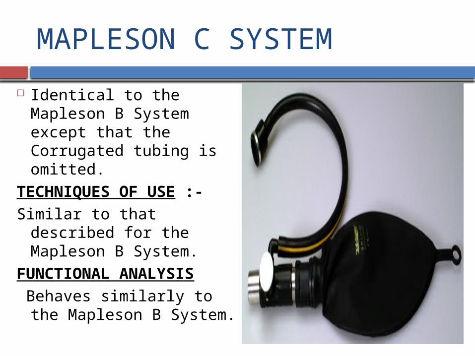
Identical to the Mapleson B System except that the Corrugated tubing is omitted.
TECHNIQUES OF USE :-
Similar to that described for the Mapleson B System.
FUNCTIONAL ANALYSIS
Behaves similarly to the Mapleson B System.

MAPLESON C (BAGGING SYSTEM)

MAPLESON C SYSTEM

MAPLESON C SYSTEM
Also k/a “Westminster face piece”.
1) SPONTANEOUS VENTILATION – When the EXPIRATORY PAUSE is minimal, almost
as efficient as the Mapleson A but becomes less efficient as the EXPIRATORY PAUSE increases.
A FGFof 2 times Minute Volume has been recommended for spontaneous breathing.
2) CONTROLLED VENTILATION :-
A FGF of 2-2.5 times Minute Volume is recommended.

MAPLESON A,B,C

MAPLESON D SYSTEM
Have a T-piece near the patient & function similarly. The T-piece is a three way tubular connector with a –
a) Patient connection port
b) Fresh Gas port
c) Port for connection to a corrugated tubing. Popular because excess gas scavenging is relatively
easy. Most efficient during Controlled Ventilation
MAPLESON D
MAPLESON D SYSTEM
CONFIGURATION :-
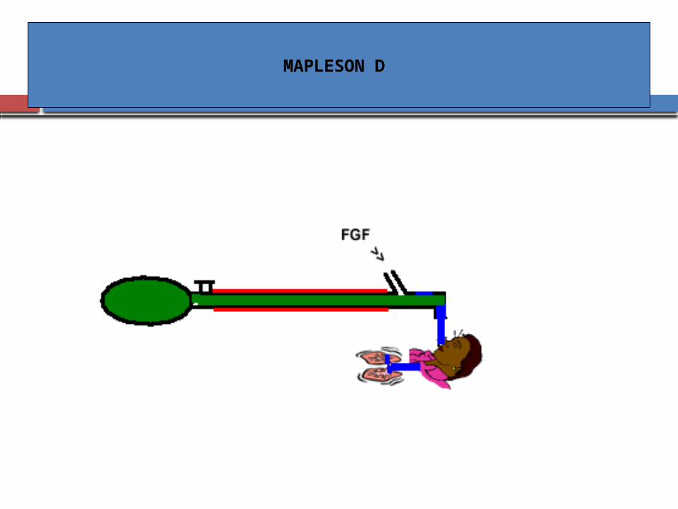
1) CLASSIC FORM – A length of tubing connects the T-piece at the patient
end to the APL Valve and the reservoir bag adjacent to it.
The length of the tubing determines the distance the user can be from the patient but has minimal effects on Ventilation.

MAPLESON D SYSTEM
The sensor or sampling site for a respiratory gas monitor may be placed between the –
a) Bag & its mount
b) Corrugated tubing & the T-piece
c) Corrugated tubing & the APL Valve
d) T-piece & the patient
MAPLESON D SYSTEM
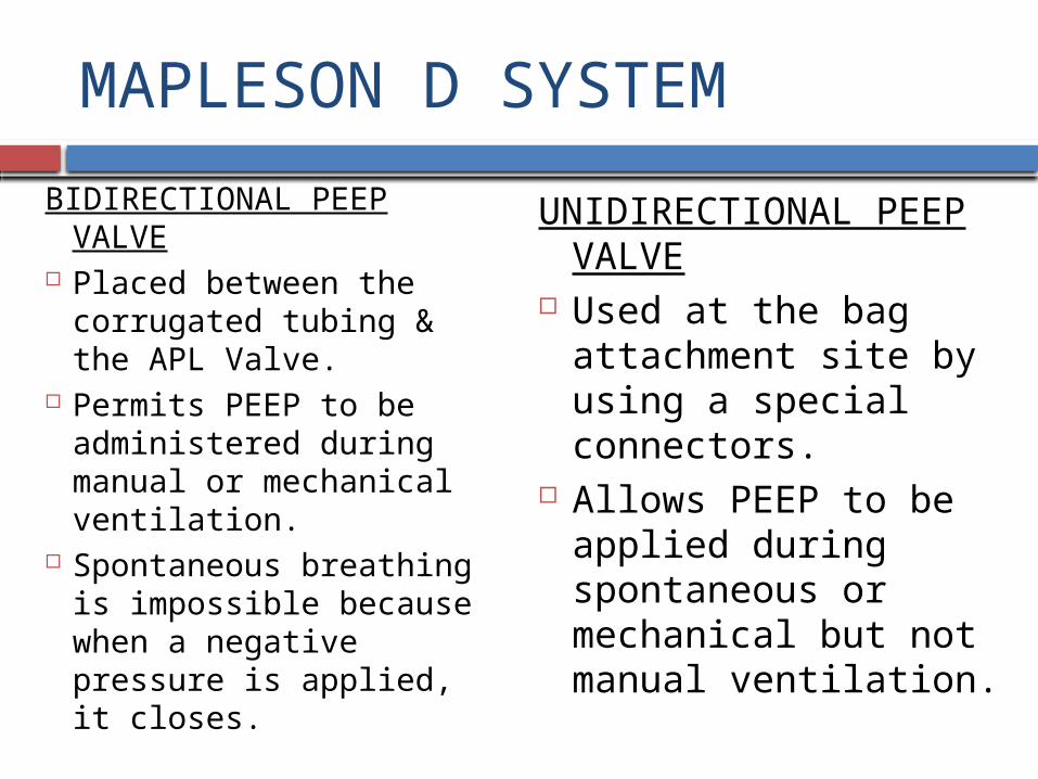
BIDIRECTIONAL PEEP VALVE
Placed between the corrugated tubing & the APL Valve.
Permits PEEP to be administered during manual or mechanical ventilation.
Spontaneous breathing is impossible because when a negative pressure is applied, it closes.
UNIDIRECTIONAL PEEP VALVE
Used at the bag attachment site by using a special connectors.
Allows PEEP to be applied during spontaneous or mechanical but not manual ventilation.
MAPLESON D SYSTEM
BIDIRECTIONAL PEEP VALVE
Placed in the hose leading to anesthesia ventilator, thus effective only during Mechanical Ventilation.
UNIDIRECTIONAL PEEP VALVE

MAPLESON D SYSTEM
2) BAIN MODIFICATION – The “Fresh Gas” supply tube runs coaxially inside the
corrugated tubing, ends at the point where the “Fresh Gas” would enter if the classic Mapleson D form were used.
The outer tube is clear so that the inner tube can be inspected.
The outer tube is narrow. Available with a metal head with channels drilled into
it, provides a fixed position for the reservoir bag & APL Valve and attachment of corrugated tubing.
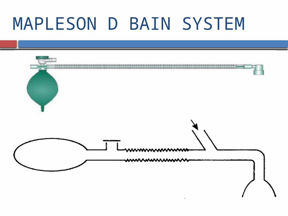
MAPLESON D BAIN SYSTEM

Bain modification of Mapleson D system
Originally modified by Bain & Spoerel in 1972.
Is co-axial system. Usual length is 180cm. Outer tube
Diameter -22mm. Carries exhaled gas.
Inner tube Diameter-7mm. Carries fresh gas.

MAPLESON D SYSTEM
Some heads also have a “Pressure Manometer”. Long Version- used for remote anesthesia in MRI. Static Compliance is increased with a reduction in
peak inspiratory pressure & Tidal Volume with the same ventilator settings.
PEEP is increased. Longer, increased resistance to spontaneous breathing.

BAIN’S CIRCUIT

MAPLESON D SYSTEM
TECHNIQUES OF USE :-
SPONTANEOUS RESPIRATION – APL Valve is left open. Excess gases are vented during expiration.
MANUALLY CONTROLLED/ASSISTED VENTILATION Partial closure of APL Valve Squeezing the bag. Excess gases are vented during inspiration.

MAPLESON D SYSTEM
MECHANICALLY CONTROLLED VENTILATION – Connecting the hose from a ventilator in place of the
reservoir bag. Closing the APL Valve. Excess gases are vented through the ventilator spill
valve.
MAPLESON D SYSTEM
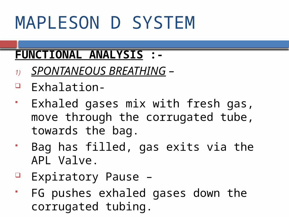
FUNCTIONAL ANALYSIS :-
1) SPONTANEOUS BREATHING – Exhalation- Exhaled gases mix with fresh gas, move through the
corrugated tube, towards the bag. Bag has filled, gas exits via the APL Valve. Expiratory Pause – FG pushes exhaled gases down the corrugated tubing.

MAPLESON D - Spontaneous respiration

MAPLESON D SYSTEM
Inspiration – Patient will inhale gas from the
FG inlet & the corrugated tubing.
FG flow is
a)High- All the gases drawn from the corrugated tube will be FG.
b)Low- Exhaled gas containing Co2 will be inhaled, ventilatory pattern will help to determine the amount of Rebreathing.
MAPLESON D SYSTEM
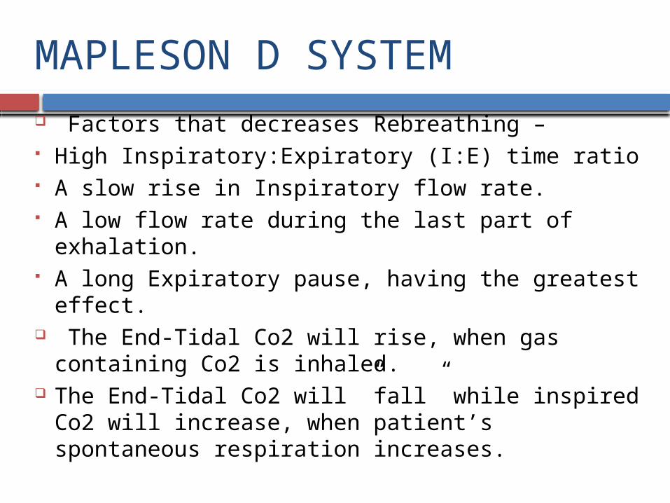
Factors that decreases Rebreathing – High Inspiratory:Expiratory (I:E) time ratio A slow rise in Inspiratory flow rate. A low flow rate during the last part of exhalation. A long Expiratory pause, having the greatest effect. The End-Tidal Co2 will rise, when gas containing Co2
is inhaled. The End-Tidal Co2 will ”fall” while inspired Co2 will
increase, when patient’s spontaneous respiration increases.

MAPLESON D SYSTEM
End-Tidal Co2 reaches “Plateau” no matter how hard the patient works, the End-Tidal Co2 cannot be lowered further.
End-Tidal Co2 will “rise”, when the patient’s respiration is depressed.
End-Tidal Co2 depends on both the ratio of Minute Volume & FGF and their absolute values.
Expired Volume > FGF, end-tidal Co2 will be determined mainly by FGF.

MAPLESON D SYSTEM FGF > Minute Volume, end-tidal Co2 will be
determined mainly by Minute Volume. Recommendations for FGF based on body weight
vary from 100-300 ml/kg/min. FGF should be 1.5 to 3.0 times the Minute Volume. FGF = Total ventilation (Adequate). FGF of 4000-4700 ml/m2/min have been
recommended.
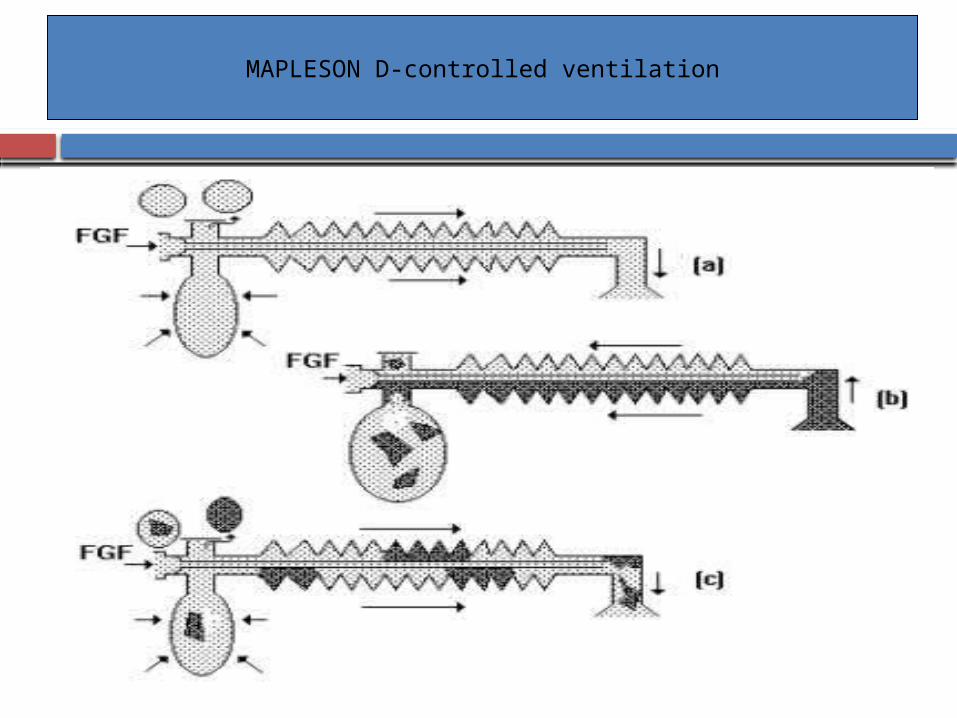
MAPLESON D-controlled ventilation

MAPLESON D SYSTEM
2) CONTROLLED VENTILATION – Exhalation- Gases flow from the patient down to the corrugated
tubing. FG enters the tubing. Expiratory Pause- FGF continues, pushes exhaled gases down to the
tubing.
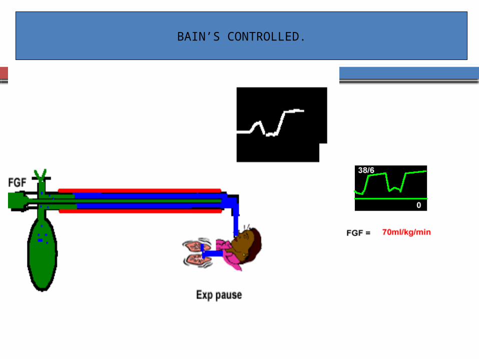
BAIN’S CONTROLLED.

MAPLESON D SYSTEM
Inspiration – FG & gas from the corrugated tubing enter the
patient. FGF is “low”, exhaled gases may be inhaled.
Increased Rebreathing- Inspiratory time is prolonged Respiratory Rate is increased Adding an Inspiratory Plateau

MAPLESON D SYSTEM
Decreased Rebreathing – Long Expiratory Pause, FG can flush exhaled gases
from the tubing. FGF is “high”- Less rebreathing End-Tidal Co2 is determined mainly by Minute
Ventilation, Tidal Volume, the volume of the expiratory limb & Expiratory Resistance.
Minute Volume > FGF , FGF is the main factor controlling Co2 elimination.
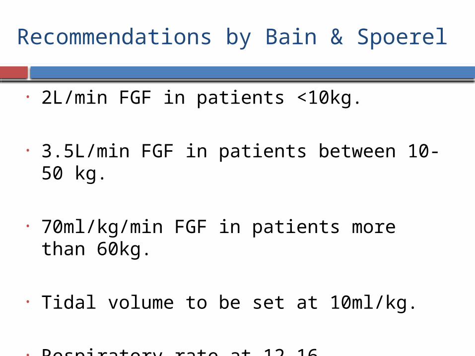
Recommendations by Bain & Spoerel
• 2L/min FGF in patients <10kg.
• 3.5L/min FGF in patients between 10-50 kg.
• 70ml/kg/min FGF in patients more than 60kg.
• Tidal volume to be set at 10ml/kg.
• Respiratory rate at 12-16 breaths/min.
MAPLESON D SYSTEM
The higher the FGF, the lower the End-Tidal Co2. A series of “Curves” can be constructed when we
combine FGF, Minute Volume & Arterial Co2 levels. To produce a given PaCo2, an infinite number of
combinations of FGF & Minute Volume can be used.
High FGF & low Minute Volumes or high Minute Volumes & low FGF or combinations in between can be used.
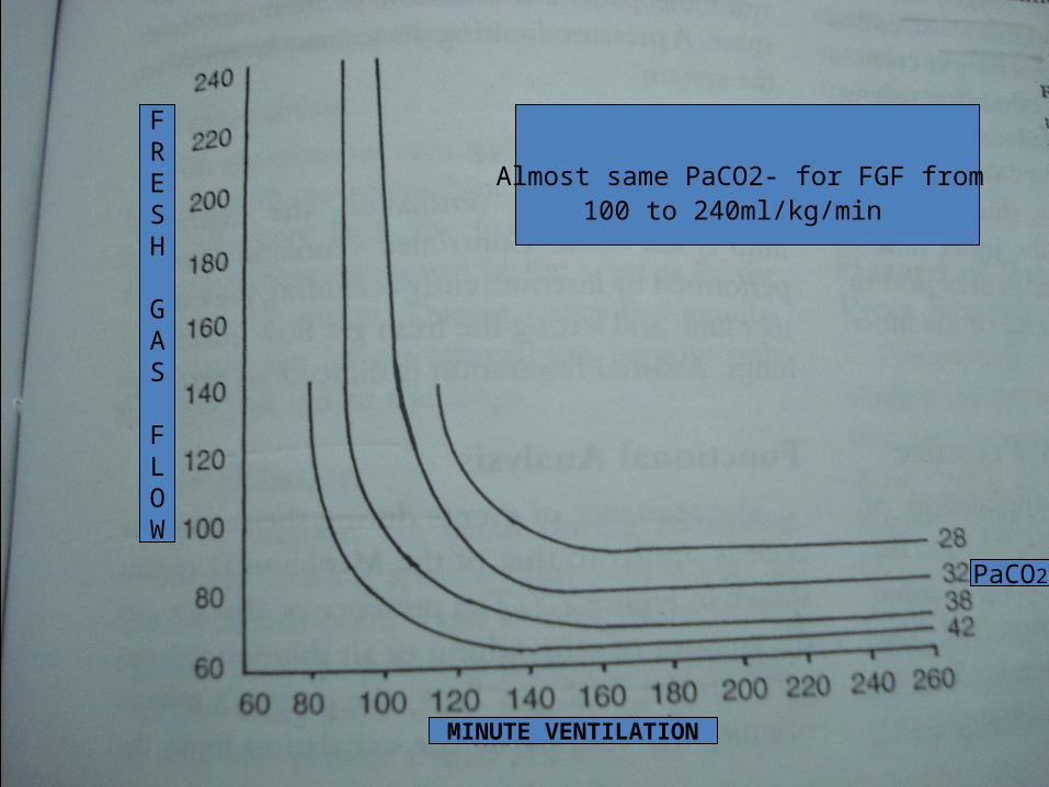
MINUTE VENTILATION
FRESH
GAS
FLOW
PaCO2
Almost same PaCO2- for FGF from 100 to 240ml/kg/min

MAPLESON D SYSTEM
At the Left, with a “High” FGF, Circuit is a nonrebreathing and end-tidal Co2 depends only on Ventilation. Uneconomical, associated with lost heat and humidity.
End-Tidal Co2 depends on Minute Volume. On the Right, region of hyperventilation and partial
rebreathing is present. End-Tidal Co2 is regulated by adjusting the FGF.

MAPLESON D SYSTEM
Lower FGF and increased rebreathing are associated with :-
1) Higher humidity
2) Less heat loss
3) Greater fresh gas economy Hyperventilation can be used without inducing
hypocarbia. Individual differences in Dead Space: Tidal Volume are
minimized at high levels of Minute Volume. So, it is useful to aim for the right side of the graph.

MAPLESON D SYSTEM
In patients with Stiff Lungs, poor cardiac performance or Hypovolemia , using the “Left” side of the graph and a relatively small total ventilation with a high FGF may be better.
Formulas to predict FGF requirements have been based on-
1)Body Weight
2)Minute Volume
3)Body Surface Area With Assisted Ventilation, the efficacy is intermediate
between that for spontaneous & controlled ventilation
MAPLESON D SYSTEM
BAIN SYSTEM HAZARDS :- Inner tube becomes detached from its connections at
either end or develops a leak at the machine end. FG supply tube becomes kinked or twisted. System is incorrectly assembled(standard corrugated
tubing). A defect in the metal head , FG & Exhaled gas mix.
The entire limb becomes Dead Space.

MAPLESON D SYSTEM
PREUSE CHECKS:- Tested for “Leaks” by occluding the patient end,
closing the APL Valve & pressurizing the system. APL Valve is then opened. Bag should deflate easily, if the valve & Scavenging
system are working properly. Either the user or a patient should breathe through the
system to detect obstructions

MAPLESON D SYSTEM
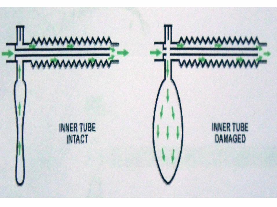
To confirm the integrity of the inner tube in Bain modification –
1) Performed by setting a low flow on the oxygen flowmeter & occluding the inner tube(with a finger or the barrel of a small syringe) at the patient end while observing the flowmeter indicator. Intact inner tube & correctly connected, indicator will fall.
2) Activating the oxygen flush & observing the bag. A venturi effect caused by the high flow at the patient end will create a negative pressure in the outer exhalation tubing , bag deflate. Non-intact inner tube, bag inflate slightly- PETHICK TEST

CPAP
CONTINUOUS POSITIVE AIRWAY PRESSURE :- One lung ventilation, using double lumen tube , a
modified Mapleson D System attached to the lumen, leading to the nondependent lung is used to apply CPAP to that lung.
Configurations –
a) A source of oxygen is connected to the system.
b) APL Valve is set to maintain the desired pressure.
c) PEEP Valve, added to function as a high pressure relief device.
MAPLESON E SYSTEM
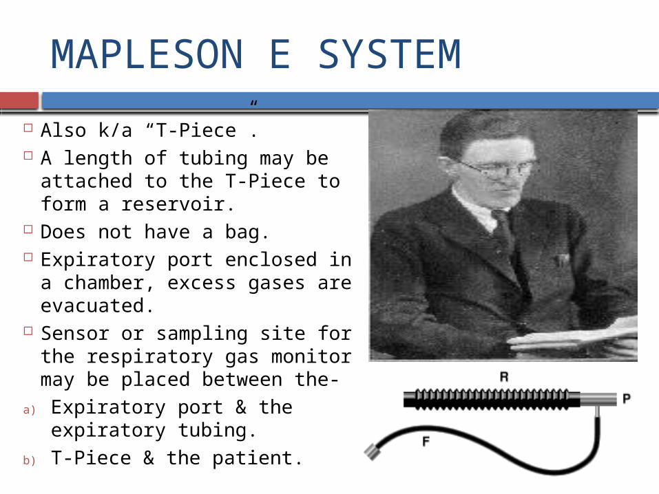
Also k/a “T-Piece”. A length of tubing may be attached
to the T-Piece to form a reservoir. Does not have a bag. Expiratory port enclosed in a
chamber, excess gases are evacuated.
Sensor or sampling site for the respiratory gas monitor may be placed between the-
a) Expiratory port & the expiratory tubing.
b) T-Piece & the patient.

MAPLESON E SYSTEM
Modifications –
a) FG Inlet, extending inside the body of the T-Piece, towards the patient connection to minimize Dead Space.
b) A pressure-limiting device Its uses has decreased because of the difficulty in
Scavenging excess gases. Commonly used to administer oxygen or humidified
gas to patients breathing spontaneously. Used initially for pediatric patients undergoing palate
repair & intracranial surgery.

MAPLESON E SYSTEM
TECHNIQUES OF USE :-
1) SPONTANEOUS VENTILATION- Expiratory limb is open to the atmosphere.
2) CONTROLLED VENTILATION – Intermittently occluding the expiratory limb, allowing
the FGF to inflate the lings. Assisted respiration is difficult to perform.

MAPLESON E SYSTEM
FUNCTIONAL ANALYSIS – The presence or absence & the amount of Rebreathing
or Air Dilution will depend on the –
a) Fresh Gas flow
b) Patient’s Minute Volume
c) Volume of the exhalation limb
d) Type of Ventilation( Spontaneous or Controlled)
e) Respiratory Pattern

MAPLESON E SYSTEM
REBREATHING –
1) Sponatneous Ventilation – No rebreathing can occur, if
there is no exhalation limb. Expiratory limb, FGF
needed to prevent rebreathing.
2) Controlled Ventilation – No rebreathing because
only FG will inflate the lungs

MAPLESON E SYSTEM
AIR DILUTION –
1) Controlled Ventilation- No air dilution
2) Spontaneous Ventilation- Volume of the tubing > patient’s Tidal Volume, no air
dilution occur. Air dilution can be prevented by providing a FGF that
exceeds the peak inspiratory flow rate( normally 3-5 times the Minute Volume) , if expiratory limb is absent or if the volume of the limb < patient’s Tidal Volume.

MAPLESON E SYSTEM
Air Dilution can be prevented by FGF of two times Minute Volume & a reservoir volume , one-third of the Tidal Volume.
HAZARDS – Controlling Ventilation by
intermittently occluding the expiratory limb may lead to –
1) Overinflation
2) Barotrauma The Pressure-Buffering effect of
the bag is absent. No APL Valve to moderate the
pressure in the lungs.

MAPLESON F SYSTEM
Also k/a Jackson-Rees, Rees, Jackson-Rees modification of the T-Piece
Has a bag with a mechanism for venting excess gases, like a “Hole” in the tail or side of the bag , occluded by using a finger to provide pressure.
May be fitted with a device to prevent the bag from collapsing and allowing excess gases to escape.
An anesthesia Ventilator may be used in place of the bag.

JACKSON REES MODIFICATION

MAPLESON F WITH APL VALVE
MAPLESON F SYSTEM
An APL Valve near the patient connection to provide protection from high pressure.
Scavenging can be performed by -
A) Enclosing the bag in a chamber from which waste gases are suctioned.
B) Attaching various devices to the relief mechanism in the bag.
MAPLESON F SYSTEM
TECHNIQUES OF USE –
1) SPONTANEOUS RESPIRATION- The relief mechanism is left fully open.
2) ASSISTED/CONTROLLED RESPIRATION- The relief mechanism is occluded sufficiently to
distend the bag. Respiration can be controlled or assisted by squeezing
the bag. Inspiration, Hole in the bag can be occluded by the
user’s finger.

MAPLESON F SYSTEM
3) MECHANICAL VENTILATION – Bag is replaced by the hose from a ventilator. HME can be used either by –
a) Inserting it between the patient & the T-Piece
b) Using the gas sampling port on the HME, as the FG inlet. Spontaneous respiration, most of the FG being vented
from the distal end of the expiratory limb. To prevent this –
a) Expiratory limb can be partially or totally occluded
b) FG flow is increased + HME not used
MAPLESON F SYSTEM
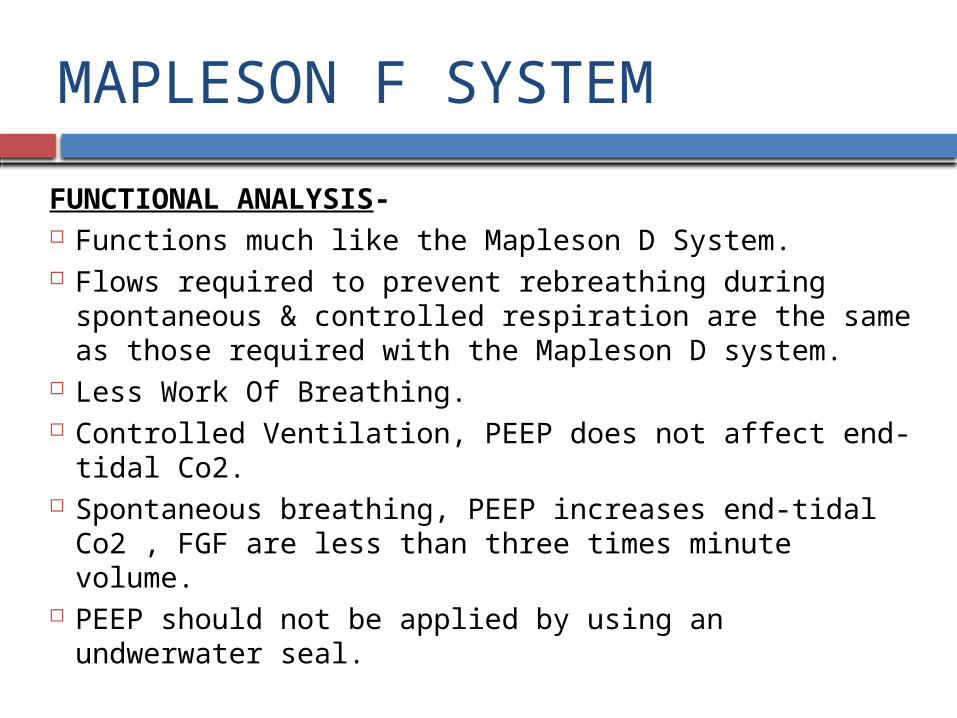
FUNCTIONAL ANALYSIS- Functions much like the Mapleson D System. Flows required to prevent rebreathing during spontaneous
& controlled respiration are the same as those required with the Mapleson D system.
Less Work Of Breathing. Controlled Ventilation, PEEP does not affect end-tidal Co2. Spontaneous breathing, PEEP increases end-tidal Co2 ,
FGF are less than three times minute volume. PEEP should not be applied by using an undwerwater seal.

MAPLESON F SYSTEM
HME , during an inhalation induction – Increaed resistance will result in more of the FGF entering the expiratory limb & delaying induction.
HAZARDS – Because of a bag in the system, excessive pressure is
less likely to develop. Same as those described for the Mapleson E System. If a ventilator that uses a ram of oxygen to produce
inspiration is used, a disconnection at the common gas outlet may not be detected by an airway pressure monitor due to the high resistance of the FG tubing.

Mapleson Systems

What FGF’s are needed?
Mapleson Systems Uses FGF SV FGF IPPV
A MagillLack
SpontaneousGen Anaesthesia
70-100 ml/kg/min Min 3 x MV
B Very uncommon, not in use today
C ResuscitationBagging
Min 15/pm
D Bain SpontaneousIPPV, Gen. Anaes
150-200 ml/kg/min
70-100 ml/kg/min
E Ayres T Piece Very uncommon, not in use today
F Jackson Rees Paediatric <25 Kg
2.5 – 3 x MVMin 4 /pm
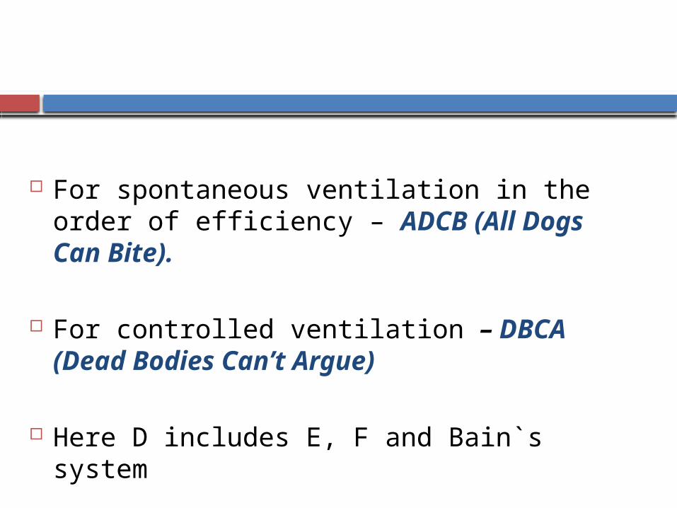
For spontaneous ventilation in the order of efficiency – ADCB (All Dogs Can Bite).
For controlled ventilation – DBCA (Dead Bodies Can’t Argue)
Here D includes E, F and Bain`s system

RESPIRATORY GAS MONITORING WITH THE MAPLESON SYSTEMS
All of the Mapleson systems except the A System have the FG inlet near the patient connection port, make it difficult to get a reliable sample of exhaled gases.
Four Sampling sites at the –
1) Junction of the breathing system & elbow connector
2) The corner of the elbow connector
3) 2 cm distal in the elbow connector
4) The Tracheal tube connector
RESPIRATORY GAS MONITORING WITH THE MAPLESON SYSTEMS
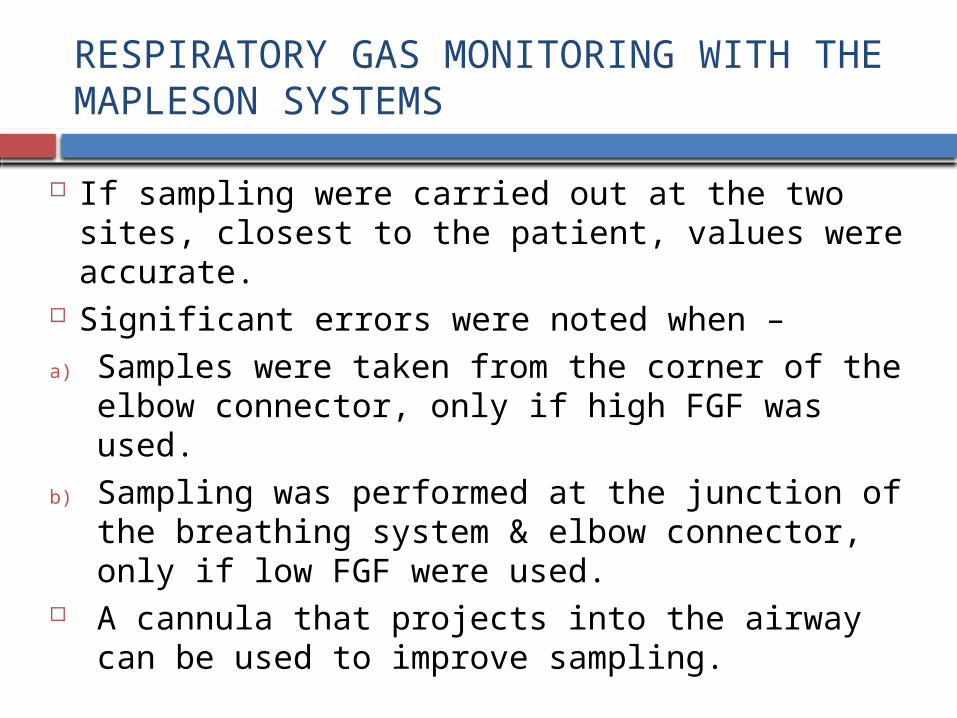
If sampling were carried out at the two sites, closest to the patient, values were accurate.
Significant errors were noted when –
a) Samples were taken from the corner of the elbow connector, only if high FGF was used.
b) Sampling was performed at the junction of the breathing system & elbow connector, only if low FGF were used.
A cannula that projects into the airway can be used to improve sampling.
RESPIRATORY GAS MONITORING WITH THE MAPLESON SYSTEMS
In infants and children –
a) Sampling at the junction of the tracheal tube and breathing system resulted in “falsely low end-tidal Co2” values in patients weighing less than 8kg.
b) The accuracy of measurements can be improved by inserting a small HME between the breathing system and the tracheal tube connector.

ADVANTAGES
Simple, Inexpensive and rugged. No moving parts except the APL Valve. Components are easy to disassemble and can be
disinfected or sterilized in a variety of ways. A popular choice to provide positive pressure
ventilation in emergencies. Variations in Minute Volume affect end-tidal Co2. In coaxial systems(Lack, Bain), the inspiratory limb is
heated by the warm exhaled gas in the coaxial expiratory tubing.

ADVANTAGES
Resistance is usually low at flows . Work Of Breathing during spontaneous ventilation is less
but not always. Sometimes WOB increases, if the APL Valve is not oriented properly.
Lightweight systems and not bulky. Not cause “Drag” on the mask or Tracheal tube or
accidental extubation. Easy to position conveniently. A long Mapleson D System with an aluminium APL
Valve may be used to ventilate a patient in the MRI Unit.

ADVANTAGES
Compression and Compliance volume losses are less. Changes in FG concentrations result in rapid changes
in Inspiratory gas composition. No Co2 absorbent, no production of possibly toxic
products such as Carbon Mononoxide and Compound A.

DISADVANTAGES
Require high gas flows . Higher costs, increased atmospheric pollution and
difficulty assessing spontaneous ventilation. Inspired heat and humidity tend to be low, unless a
humidification device is used. Optimum FGF may be difficult to determine. Necessary to change the flow when changing from
spontaneous to controlled ventilation or vice versa. Anything that causes FGF to be lowered, presents a
hazard, because rebreathing may occur.

DISADVANTAGES
APL Valve is located close to the patient in Mapleson A,B and C Systems ; inaccessible to the user. Scavenging is awkward. Can be overcome by using the Lack modification of the Mapleson A.
Mapleson E and F Systems are difficult to scavenge & Air Dilution can occur with the Mapleson E System.
Not suitable for patients with malignant hyperthermia because FGF is not enough to remove the increased Co2 Load.

THANK YOU
.