manufacturers of rf and microwave components and...
TRANSCRIPT

[email protected] • www.cormic.com • P 724.940.7556 • F 724.940.7707
Manufacturers of RF and Microwave Components and AssembliesSpecialist in RF Filters, Power amplifiers and RF Switches

RF & MICROWAVE FILTERS
Filter Types Band Pass, Low Pass, High Pass, Band Reject, All Pass (Delay Line or Phase Shifter)
Packaging Surface mountable (SMT), Drop-in or connectorized
At CMI, we have the ability to place transmission zeros, commonly known as cross-coupling, to achieve tough rejection specifications. This gives us the ability to package the filters in the smallest mechanical form factors possible.
With over two decades of microwave filter design experience, we have created a digital library of off the shelf designs (up to 40 GHz) that enables us to create prototypes in less than 3 weeks in many cases. We can leverage our in-house machine shop so that our digital drawings can be directly downloaded through the use of Mastercam.
Filter Technology Types• LC (discrete components)• Crystal• Microwave
• Microstrip, stripline, suspended stripline, slabline• Combline• Cavity• Interdigital• Tubular• Waveguide
• Ceramic Resonator• Helical

DIPLEXERS & MULTIPLEXERS
Diplexing:A Diplexer is a frequency division multiplexing passive device. Diplexers combine two
different frequency bands onto one common port. A low pass filter and a high pass filter can be diplexed as can be two band pass filters or a band pass filter to either a high pass or a low pass filter. The key requirement is that the pass bands of the two filters to be diplexed do not overlap.
Application: Filter ‘A” is connected to a receiver while filter “B” is connected to a transmitter cou-pled to a common antenna port.
Multiplexing:Multiplexing is the combining of multiple (more than two) band pass filters to a common
port while maintaining the filter performance of each band.
Why CMI:We are experts in multiplexing. By using different and various filter types, we separate
ourselves from our competition. (For filter types refer to our description included on the RF and Microwave filter page) We have multiplexed over 6 channels onto a common port. (See picture below)
At CMI, we have the ability to develop custom filter designs optimized to each customer’s requirements. We design with the optimal architecture and filter elements to meet most stringent insertion loss specifications.

RF SWITCH & CONTROL PRODUCTS
Standard RF Pin Diode Switches • Frequencies to 40 GHz • TTL Compatible at +/- 5 VDC • Power to 1 Watt CW • Switching speeds of 20 ns
RF Switch Matrices • Mechanical sizes: 1U to 10U •Matrixconfigurations:Blocking,Non-Blocking, andSuperNon-Blocking • Speeds to 5 µs with FPGA option • Frequencies to 40 GHz •Control:USB,10/100Base-T,Frontpanelentry, SNMPcontrolandmonitoring •Expandableinblocksof8by8 •Isolationto80dB
Electro-Mechanical RF Switch • Frequencies to 40 GHz •Typicalswitchingspeeds:20ms • Power to 100W •Insertionloss:.2dBtypical@3GHz
High Power RF Pin Diode Switches • Frequencies to 20 GHz •PeakPowerto5KW • Average Power of 100 W • Switching speeds of 200 ns • Switching rate to 4 MHz

LOW NOISE AMPLIFIERSElectrical Specifications:
• Single or multiple amplified channels in a common package • Frequencies to 20 GHz • Narrow or broadband • Low Noise figure • Impedance: 50 or 75 Ohm • Wide operating voltage range
Electrical Specifications:
• Frequencies to 20 GHz • Narrow or broadband • Power Output to hundreds of watts • Linear or CW types • Optional built-in amplifier control and safeguards • Flexible operating voltage • Impedance: 50 or 75 Ohm • Non-Hermetic and Hermetic packages available • Industry leading Efficiency
RF POWER AMPLIFIERS
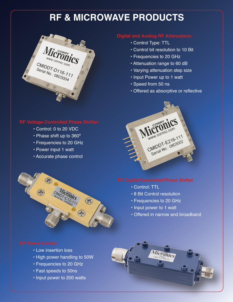
RF & MICROWAVE PRODUCTS
Digital and Analog RF Attenuators: • Control Type: TTL • Control bit resolution to 10 Bit • Frequencies to 20 GHz • Attenuation range to 60 dB • Varying attenuation step size • Input Power up to 1 watt • Speed from 50 ns •Offeredasabsorptiveorreflective
RF Digital Controlled Phase Shifter • Control: TTL • 8 Bit Control resolution • Frequencies to 20 GHz • Input power to 1 watt • Offered in narrow and broadband
RF Voltage Controlled Phase Shifter: • Control: 0 to 20 VDC • Phase shift up to 360º • Frequencies to 20 GHz • Power input 1 watt • Accurate phase control
RF Power Limiter • Low insertion loss • High power handling to 50W • Frequencies to 20 GHz • Fast speeds to 50ns • Input power to 200 watts
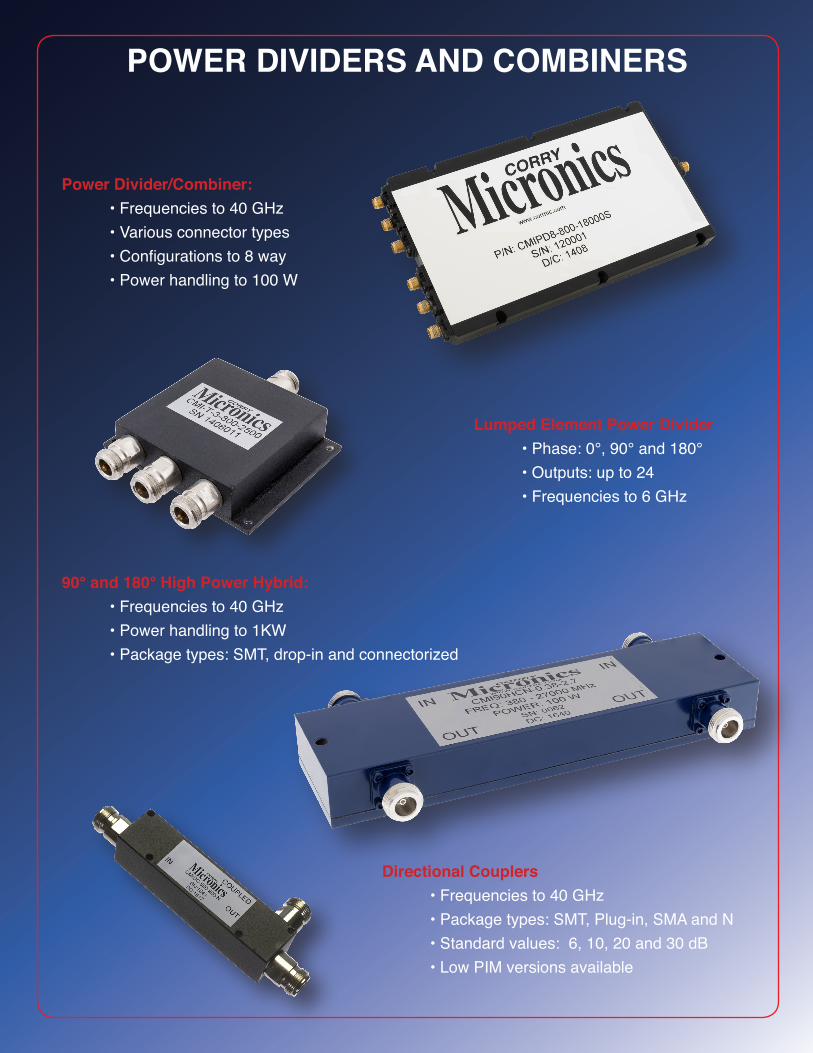
POWER DIVIDERS AND COMBINERS
Power Divider/Combiner: • Frequencies to 40 GHz • Various connector types •Configurationsto8way •Powerhandlingto100W
90° and 180° High Power Hybrid: • Frequencies to 40 GHz •Powerhandlingto1KW •Packagetypes:SMT,drop-inandconnectorized
Lumped Element Power Divider •Phase:0°,90°and180° •Outputs:upto24 • Frequencies to 6 GHz
Directional Couplers • Frequencies to 40 GHz •Packagetypes:SMT,Plug-in,SMAandN •Standardvalues:6,10,20and30dB •LowPIMversionsavailable

CUSTOM ENGINEERED PRODUCTSEngineering Design • Microwave Filters and Diplexers • RF Switches • RF switch matrices • Antenna and waveguide assemblies •RFPowerAmplifier •Switchedfilterassemblies • Custom microwave assemblies • Broadband splitters & combiners • Hi-power directional couplers • Hi-power limiters
RF Communications Test Assembly • Frequency Range: 1.4 to 2.7 GHz • Port to Port isolation: 50dB min • Low insertion loss: 0.5 dB max • Coupled ports: 26+/-2 dB • Phase balance: +/-6°
Three Channel Attenuator • Frequency range: 400 MHz to 3000 MHz • Low PIM: -160dBc typical and -155dBc minimum • Power handling: Average 100 Watts per channel • Peak Power to 3 KW • Attenuation: • 15-19 dB from 400 MHz to 700 MHz • 14-16 dB from 700 MHz to 3000 MHz • Isolation: >80dB
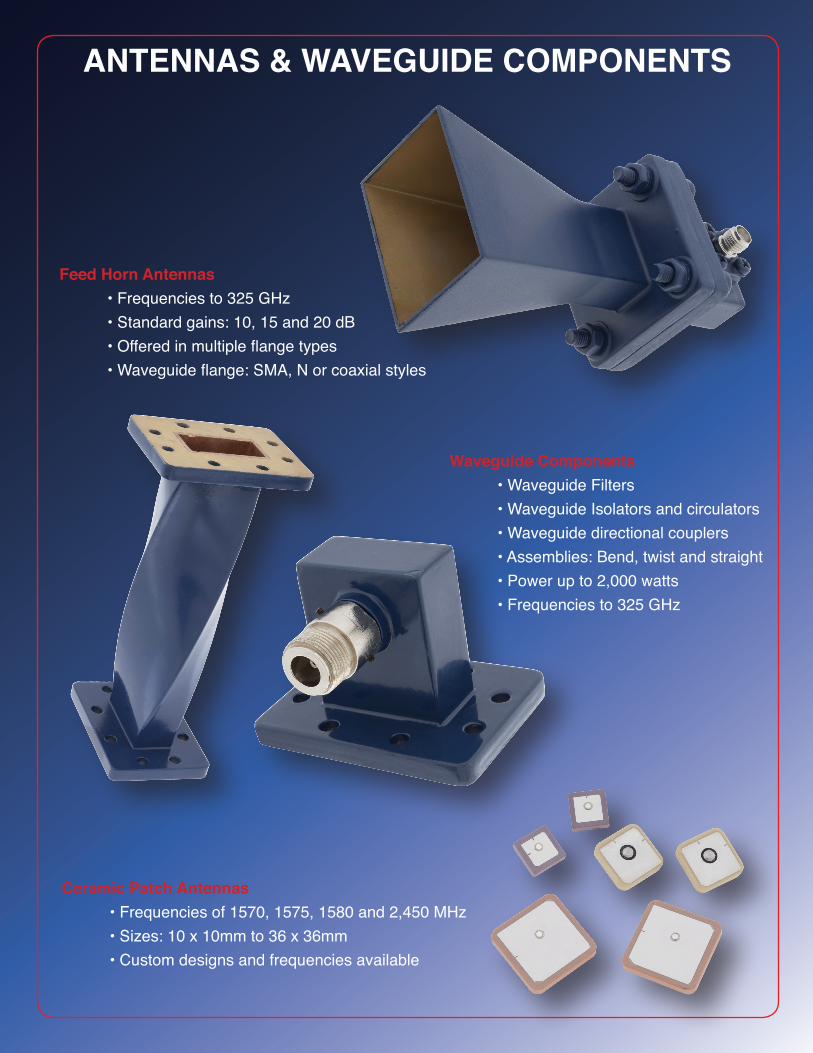
ANTENNAS & WAVEGUIDE COMPONENTS
Feed Horn Antennas • Frequencies to 325 GHz • Standard gains: 10, 15 and 20 dB •Offeredinmultipleflangetypes •Waveguideflange:SMA,Norcoaxialstyles
Ceramic Patch Antennas •Frequenciesof1570,1575,1580and2,450MHz •Sizes:10x10mmto36x36mm • Custom designs and frequencies available
Waveguide Components • Waveguide Filters • Waveguide Isolators and circulators • Waveguide directional couplers •Assemblies:Bend,twistandstraight •Powerupto2,000watts • Frequencies to 325 GHz

SINGLE LINE FILTERS
High Current Filters
Mechanical Sizes: 5⁄8”-24 or M12- 0.75Electrical Specifications:• Circuit Type: “LB”, “LT”, “Pi”, “C”• Voltage range to 200VDC or 140VAC• Capacitance values to 0.22µF• Available in 50 to 200A
Hermetic Filters
Mechanical Sizes: 1⁄4”-28 or 5⁄16”-24 Electrical Specifications:• Circuit Type: “C”, “LB”, “LT”, “Pi” & “T”• Voltage range to 400VDC or 240VAC • Capacitance values to 1.4µF
Press-In Filters
Mechanical Size: .156” FlangeElectrical Specification: • Circuit Type: “C” • Voltage range to 200VDC• Capacitance values to 50,000pF
Glass-to-Metal Seals
Mechanical Sizes: 0.076 to 0.175Electrical Specifications: • DC or 50 Ohm impedance
Spanner Head Filters
Mechanical Sizes: #2-56 to #8-32Electrical Specifications:• Circuit Type: “C”,• Voltage range to 200VDC• Capacitance values to 10,000pF
Surface Mount Filters
Mechanical sizes: L=.315 or .394Pad Layout: 0.102 or 0.202Electrical Specifications:• Circuit Type: “C” or “Pi” • Voltage range to 100VDC • Capacitance values to 8,200pF
Solder-In Filters
Mechanical Size: .156” FlangeElectrical Specifications:• Circuit Type: “C” • Voltage range to 200VDC• Capacitance values to 50,000pF
Bolt-In Filters
Mechanical Sizes: #2-56 to 3⁄8”-32 Electrical Specifications:• Circuit Types: “C”, “L”, “Pi” • Voltage range to 2500 VDC • Capacitance values to 50,000pF
Eyelet Style/Filter Pins
Mechanical Sizes: 0.138” to 0.195” Flange Electrical Specifications: • Circuit Type: “C” or “Pi” • Voltage range to 200VDC • Capacitance values to 5,000pF

MULTI-LINE FILTERSFiltered Terminal Blocks
Mechanical Size: 7⁄16” Spacing, #6 & #8 ScrewsElectrical Specification:• Circuit Types: “C”, “Pi”• Voltage range to 300VDC, 240VAC• Capacitance values to 30,000pF• Current ratings up to 200A
Ceramic Tubular FilteredD-Sub Connectors
Mechanical Size: Standard and High Density D-Sub Configurations in 9, 15, 25, 37 & 50 pin sizesElectrical Specification:• Circuit Types: “C”, “Pi”• Voltage range to 100VDC• Capacitance values to 47,000pF
Filter Plates
Mechanical Size: 0.100” and 2 mm SpacingsElectrical Specification:• Circuit Types: “C”, “Pi”• Voltage range to 100VDC• Capacitance values to 5,000pF
Ceramic TubularFiltered Adapters
Mechanical Size: Standard and High Density D-Sub Configurations in 9, 15, 25, 37 & 50 pin sizesElectrical Specification:• Circuit Types: “C”, “Pi”• Voltage range to 100VDC• Capacitance values to 47,000pF
Filtered CircualerConnectors
Mechanical Size: Mil-C-38999, Mil-C-26482, Mil-C-83723, Mil-C-5015Electrical Specification:• Circuit Types: “C”, “L”, “Pi”• Voltage range to 200VDC• Capacitance values to 100,000pF
Complete Machine Shop, Assembly & Testing Services
We offer full turn-key services
• Engineering Design services • Housing maching • Tin, Silver or Gold plating • Filter Installation •Hermeticgrossorfineleaktesting • Electrical testing • Hi Pot and Hi-Current testing •Mechanicaldimensionaltesting&certification • Environmental testing

CORRY MICRONICS, INC.761 COMMONWEALTH DRIVE
SUITE 201WARRENDALE, PA 15086
P 724.940.7556F 724.940.7707
EMAIL: [email protected]