current trends in rf/microwave switch matrices introduction · current trends in rf/microwave...
TRANSCRIPT
REC Proprietary; Not For Distribution
Current Trends in RF/Microwave Switch Matrices
Introduction
An RF/Microwave Switch Matrix is commonly used in manufacturing test systems and design
verification for both commercial and military applications. With upcoming LTE/WiMAX
standards there is growing need for switch matrices for reliable ATE instrumentation (DC to 6
GHz) with fast response and reproducible performance. Typical ATE systems include HF/RF
components, redundant CPU and power supplies, hot swappable power supplies, fans and Field
upgradeable firmware. Besides routing the high frequency signals, the Switch Matrix may also
contain signal conditioning components including passive signal conditioning devices such as
combiners/splitter, attenuators, filters, and directional couplers, as well as active signal
conditioning, such as amplifiers and frequency converters. The main component of course is a
switch that is configured to fit the architecture. Since the signal routing and signal conditioning
requirements differ from design to design, RF/Microwave Switch Matrix typically has to be
custom designed.
There are six main challenges when designing a custom RF/Microwave Switch Matrix from start
to end:
1) RF/Microwave Design: RF/Microwave signal routing and signal conditioning design and
testing to satisfy specification demands for instance isolation or rejection, power
handling, spurious levels, IM and harmonics besides the obvious criteria to meet
minimum loss and VSWR over any input to output path. At times, an internal calibration
scheme comprising of hardware and software solutions is required to be embedded inside
the matrix to properly characterize the signal paths and extract a stored reference data if
necessary. Besides insertion loss, channel to channel isolation is next most important
specification usually seen in matrices.

REC Proprietary; Not For Distribution
2) Mechanical Design: Most mechanical designs can be standard 19 inches rack wide and
1U to 7U high. The depth of the enclosure can be made up to 17 inches for simple
systems and up to 30 inches for more complex systems. Compact sizes are required for
applications such as flight, space and shipboard. Sophisticated cooling mechanism is
desired for matrices that routes high power signals and contains signal conditioning
components like high power amplifiers. Various mechanical cooling structures such as
fans and heat sinks can be employed in different sizes, speed and shapes to regulate the
heat. Design of an electrically shielded enclosure or box, internal component mounting
brackets, as well as component and cabling layout are also the key requirements. The
components can be placed by performing vibration analysis within chassis to exhibit
maximum resonant frequency to meet stringent mil-spec vibration requirements.
3) DC Power and Control Hardware: The power supply and switch driver circuitry will need
to be designed and developed based on the voltage and current requirement of the
components. One of the challenging tasks in switch matrix design is to articulate power
distribution circuits and controlling hardware. As every switch matrix is custom
designed to meet spec requirements, the controlling hardware also needs to be custom
designed to meet signal routing options.
4) Software Control: A software driver will need to be developed to provide an interface
between the control hardware and test system program. A GUI can be installed on the
host computer which can interact with matrix via Ethernet, GPIB, RS232 or RS422 style
interface. Sophisticated matrices also presents challenges on designing an underlying
control software which requires mapping of switches, creating truth tables, defining logic
control structures, front end GUI design and firmware to support interaction through
various controlling ports.
5) Servicing Plan: A servicing plan will need to be developed to ensure the life of the switch
matrix. To improve the product life, design challenges also includes on selecting
components which provides higher MTBF and at the same time meets the desired
specifications. Specifically, Electromechanical switches and MEMS switches wears

REC Proprietary; Not For Distribution
down their contacts as they operate over the period of time and the consistency in
operation degrades after certain number of life cycles. Replacements of those switches
are required at certain interval based upon the projected service plan.
6) Documentation: The whole switch matrix design will have to be documented to support
maintenance, troubleshooting, operation, command structure and possible future designs.
Renaissance Electronics Corporation is an AS9100 certified company with its specialized
interest on custom design of switch matrices and RF/microwave/mm-wave subassemblies.
Renaissance has capabilities to design switch matrices with integrated driver for standard or
customized interface such as GPIB, RS232, RS485, USB, PXI or Ethernet with supporting
documentation on control and command structure. Renaissance has the expertise to design N x
M switch matrices with either Reciprocal or Non-Reciprocal, Blocking or Non-Blocking and
with either Electromechanical, Solid-State or MEMS switches.
Technology Overview Switch matrix can be designed as blocking style or non-blocking style depending upon their
architecture. Figure 1 below shows an example of blocking and non-blocking switch matrix. An
example for the blocking switch matrix can be radio and antenna system where each radio gets
connected with a unique antenna. Non-blocking switch matrix can be used in applications such
as MIMO transceivers and Satellite Ground Station receivers.
Fig. 1 Switch Matrix Architectures
SPDT SPDT
SPDT SPDT
1 1
2 2
a. Blocking Switch Matrix b. Non-Blocking Switch Matrix
∑ SPDT
SPDT
1 1
2 2 ∑

REC Proprietary; Not For Distribution
Electromechanical Design Solid-State Design
Broadband design Narrowband design
High Power Low Power
Bulkier systems Compact systems
Low insertion loss and VSWR Higher insertion loss and VSWR
Switching speeds on the order of milliseconds Faster switching speeds on the order of nanoseconds
1-2 million life-cycles Infinite life cycles
Table 1 Comparison of Electromechanical and Solid-State Switches
Coaxial Electromechanical Switches: Coaxial electromechanical switches can be divided into two categories based on their
architecture: Latching relay and Non-latching relay.
Latching: Latching relays are used for applications when long term latched states are required
and switching is not that frequent. Examples for such applications include antenna switching for
redundancy. In this type of application, the receiver/transmitter antenna switching is not
frequent as they are either switching for redundancy or only when there is a need to transmit and
receive at different location or frequency.
Non-latching: For momentary switching applications – example for such applications include
ATE to test chipset. While performing automated testing, there can be a frequent need of
changing the test ports to switch either input test signals or to direct output test signal on another
port. Due to these requirements non-latching relays are mostly suited for these kinds of
application which saves time in operation as de-energizing of coil is not required.
Electromechanical switches are broadband typically from DC up to 40GHz. They can also
handle high power, on the order of 100 Watts, over the operating frequency range. The insertion
loss can range from 0.2dB to 0.6dB and the isolation can range from 50dB to 90dB. The
REC Proprietary; Not For Distribution
switching time can range from 20 to 30 milliseconds. As suffice from the above data that
Electromechanical Designs offer better insertion loss, VSWR, power handling and isolation
specifications. However the trades off are in the cost and mechanical dimensions. The cost is
involved in machining the parts to certain dimensions, assembling, tuning the relay and
performing final tests. Electromechanical switches have larger mechanical dimensions due to
minimum connector spacing requirements for isolation and power handling, magnetic coils and
the separation between them to operate desirably.
Solid-State Design: Solid state switches have three different configurations: PIN diode, FET, and hybrid.
PIN Diode (SPDT): Switch design using PIN diode can employ shunt, series or compound
topology. It is usually difficult to achieve more than 40 dB of isolation using a single PIN diode,
either in shunt or series, at RF and higher frequencies. PIN Diodes can be designed for high
power (10s of watts) and multi-octave (DC-10 GHz) bandwidth. However, the trade off is
higher loss (~ 1dB) and lower isolation values (25 dB).
FET/GaAS (SPDT): Switching FET is a three port device, where the channel between source
and drain ports form a conduction path for the RF signal and the gate port, controls whether an
RF signal is blocked or may pass. A DC control voltage applied between the gate and channel is
required to create this function. FET switches offer relatively narrower bandwidth (700 MHz - 6
GHz), lower power (< 1 Watt), lower loss (< 0.8 dB), and higher isolation (40 dB).
Main advantages of Solid-state: Solid-state switches achieve lower cost due to large scale
semiconductor assembly and automation. They also achieve smaller footprint (transistor I/O are
on the microscopic levels) which helps on designing compact systems.
RF MEMS switches: RF MEMS switches are electro-statically actuated cantilever beams connected in a three terminal
configuration. Their functionality is analogous to a field effect transistor (FET), and the
terminals are labeled as source, gate and drain. When a DC actuation voltage is applied between
REC Proprietary; Not For Distribution
the gate ad source, the resulting electrostatic force pulls the free end of the beam into contact
with the drain. When the voltage is removed, the beam acts as a spring, generating sufficient
restoring force to open the connection between source and drain, thus breaking the circuit. In
multi-throw switches, each throw is an independently actuated cantilever beam.
RF MEMS switches provides higher reliability of >100 Billions mechanical life cycles which is
at par compared with their solid state and electromechanical counter-parts. They also provide
low insertion loss in the order of less than 0.5 dB for frequencies up to 38GHz. The isolation can
be of the order of 20dB. However, the higher isolation can be obtained by combining series and
shunt switches capped within the same package. For example, the isolation is 65dB at 2GHz and
50dB at 10GHz.
Switch Matrix Examples
1. VHF/UHF switch matrix
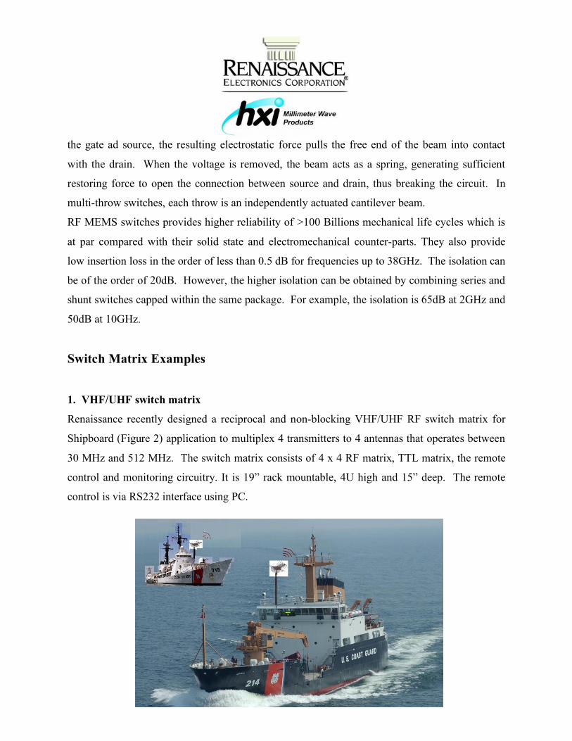
Renaissance recently designed a reciprocal and non-blocking VHF/UHF RF switch matrix for
Shipboard (Figure 2) application to multiplex 4 transmitters to 4 antennas that operates between
30 MHz and 512 MHz. The switch matrix consists of 4 x 4 RF matrix, TTL matrix, the remote
control and monitoring circuitry. It is 19” rack mountable, 4U high and 15” deep. The remote
control is via RS232 interface using PC.
REC Proprietary; Not For Distribution
Fig. 2 REC RF Switch Matrix in Coast Guard Ship Application
(Image is for illustration purposes only)
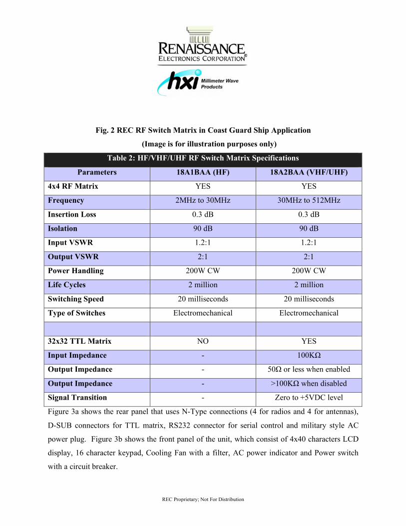
Table 2: HF/VHF/UHF RF Switch Matrix Specifications
Parameters 18A1BAA (HF) 18A2BAA (VHF/UHF)
4x4 RF Matrix YES YES
Frequency 2MHz to 30MHz 30MHz to 512MHz
Insertion Loss 0.3 dB 0.3 dB
Isolation 90 dB 90 dB
Input VSWR 1.2:1 1.2:1
Output VSWR 2:1 2:1
Power Handling 200W CW 200W CW
Life Cycles 2 million 2 million
Switching Speed 20 milliseconds 20 milliseconds
Type of Switches Electromechanical Electromechanical
32x32 TTL Matrix NO YES
Input Impedance - 100KΩ
Output Impedance - 50Ω or less when enabled
Output Impedance - >100KΩ when disabled
Signal Transition - Zero to +5VDC level
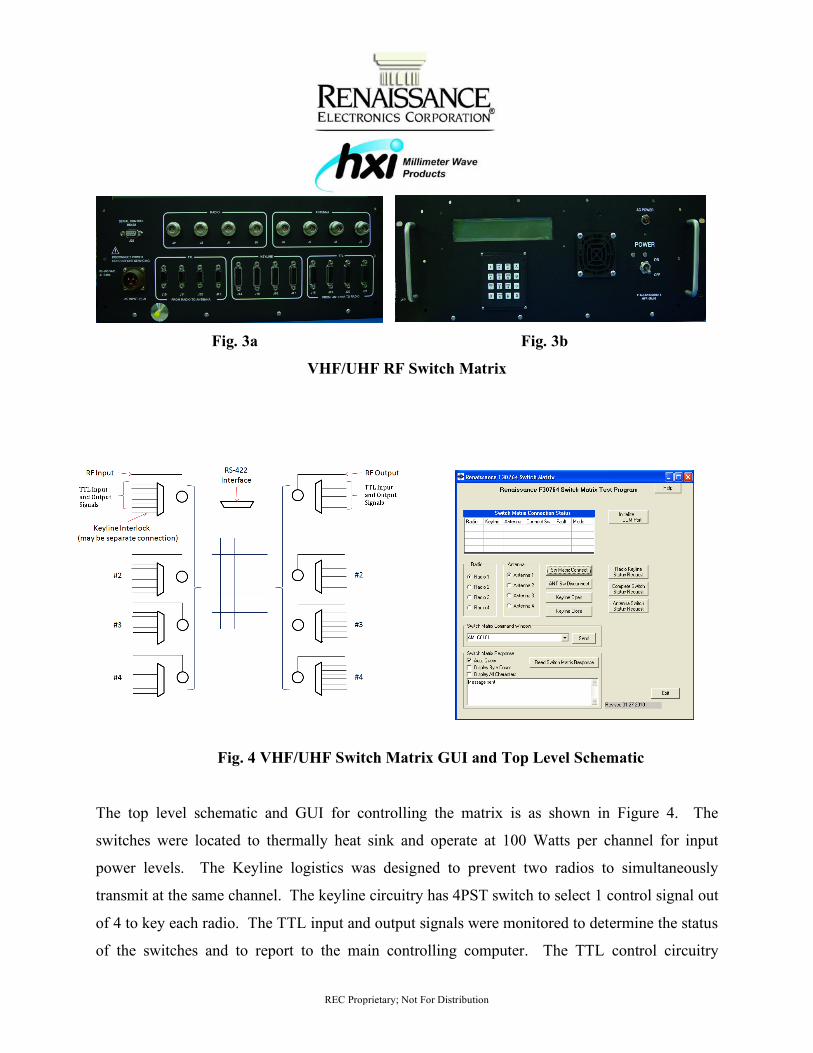
Figure 3a shows the rear panel that uses N-Type connections (4 for radios and 4 for antennas),
D-SUB connectors for TTL matrix, RS232 connector for serial control and military style AC
power plug. Figure 3b shows the front panel of the unit, which consist of 4x40 characters LCD
display, 16 character keypad, Cooling Fan with a filter, AC power indicator and Power switch
with a circuit breaker.
REC Proprietary; Not For Distribution
Fig. 3a Fig. 3b
VHF/UHF RF Switch Matrix
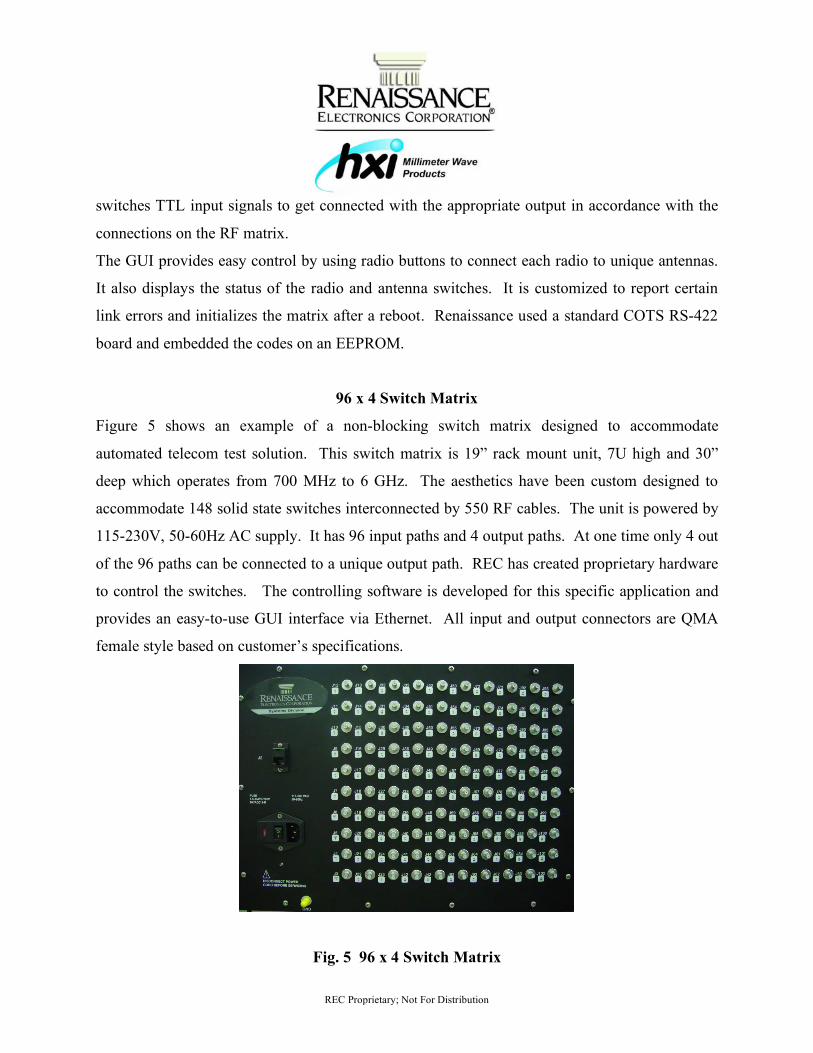
Fig. 4 VHF/UHF Switch Matrix GUI and Top Level Schematic
The top level schematic and GUI for controlling the matrix is as shown in Figure 4. The
switches were located to thermally heat sink and operate at 100 Watts per channel for input
power levels. The Keyline logistics was designed to prevent two radios to simultaneously
transmit at the same channel. The keyline circuitry has 4PST switch to select 1 control signal out
of 4 to key each radio. The TTL input and output signals were monitored to determine the status
of the switches and to report to the main controlling computer. The TTL control circuitry
REC Proprietary; Not For Distribution
switches TTL input signals to get connected with the appropriate output in accordance with the
connections on the RF matrix.
The GUI provides easy control by using radio buttons to connect each radio to unique antennas.
It also displays the status of the radio and antenna switches. It is customized to report certain
link errors and initializes the matrix after a reboot. Renaissance used a standard COTS RS-422
board and embedded the codes on an EEPROM.
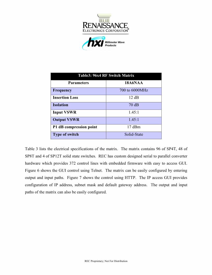
96 x 4 Switch Matrix
Figure 5 shows an example of a non-blocking switch matrix designed to accommodate
automated telecom test solution. This switch matrix is 19” rack mount unit, 7U high and 30”
deep which operates from 700 MHz to 6 GHz. The aesthetics have been custom designed to
accommodate 148 solid state switches interconnected by 550 RF cables. The unit is powered by
115-230V, 50-60Hz AC supply. It has 96 input paths and 4 output paths. At one time only 4 out
of the 96 paths can be connected to a unique output path. REC has created proprietary hardware
to control the switches. The controlling software is developed for this specific application and
provides an easy-to-use GUI interface via Ethernet. All input and output connectors are QMA
female style based on customer’s specifications.
Fig. 5 96 x 4 Switch Matrix
REC Proprietary; Not For Distribution
Table3: 96x4 RF Switch Matrix
Parameters 18A6NAA
Frequency 700 to 6000MHz
Insertion Loss 12 dB
Isolation 70 dB
Input VSWR 1.45:1
Output VSWR 1.45:1
P1 dB compression point 17 dBm
Type of switch Solid-State
Table 3 lists the electrical specifications of the matrix. The matrix contains 96 of SP4T, 48 of
SP8T and 4 of SP12T solid state switches. REC has custom designed serial to parallel converter
hardware which provides 372 control lines with embedded firmware with easy to access GUI.
Figure 6 shows the GUI control using Telnet. The matrix can be easily configured by entering
output and input paths. Figure 7 shows the control using HTTP. The IP access GUI provides
configuration of IP address, subnet mask and default gateway address. The output and input
paths of the matrix can also be easily configured.

REC Proprietary; Not For Distribution
Fig. 6 96 x 4 Switch Matrix Control Using Telnet
Fig. 7 96 x 4 Switch Matrix GUI Control Using Ethernet
Redundant Switch Matrix
REC Proprietary; Not For Distribution
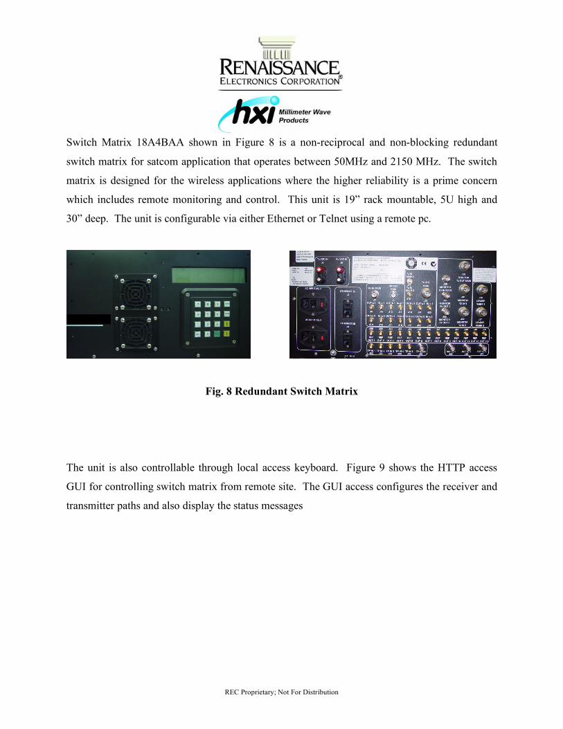
Switch Matrix 18A4BAA shown in Figure 8 is a non-reciprocal and non-blocking redundant
switch matrix for satcom application that operates between 50MHz and 2150 MHz. The switch
matrix is designed for the wireless applications where the higher reliability is a prime concern
which includes remote monitoring and control. This unit is 19” rack mountable, 5U high and
30” deep. The unit is configurable via either Ethernet or Telnet using a remote pc.
Fig. 8 Redundant Switch Matrix
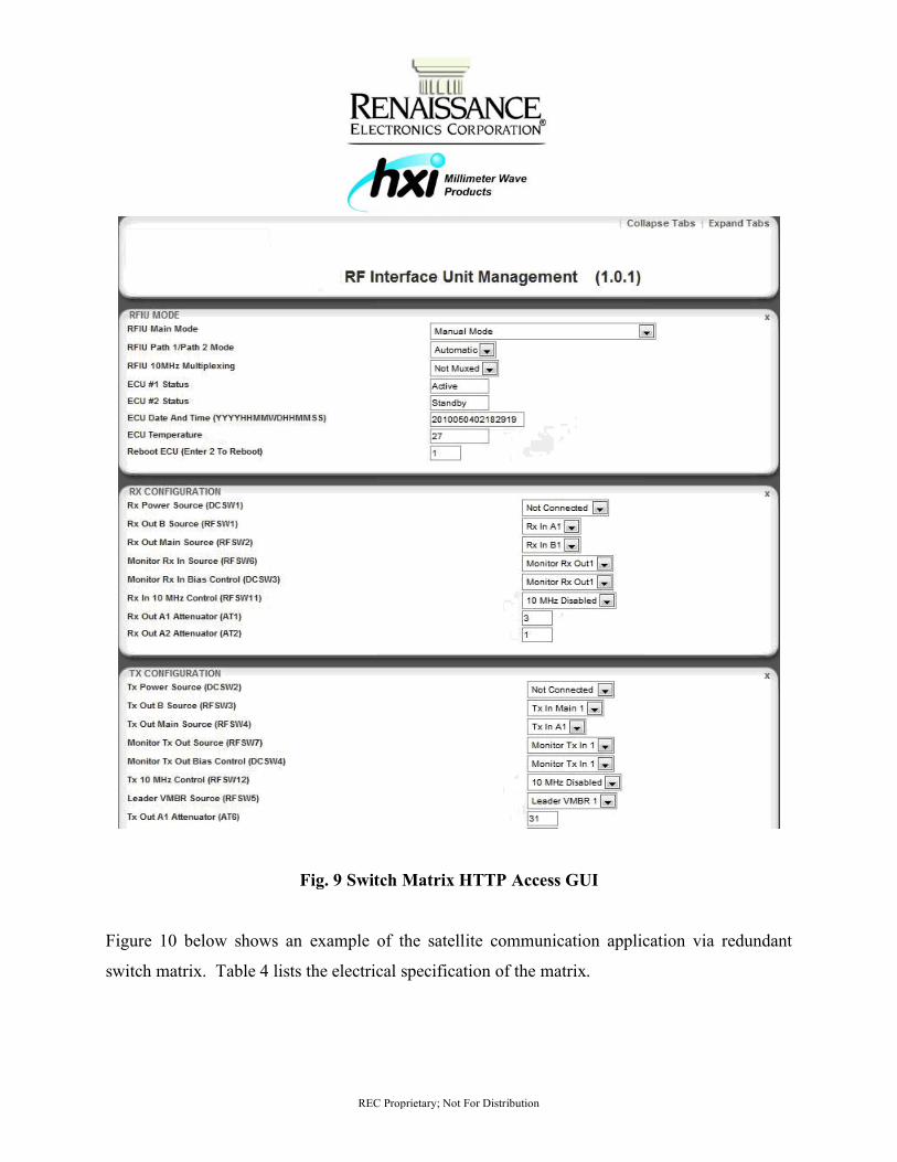
The unit is also controllable through local access keyboard. Figure 9 shows the HTTP access
GUI for controlling switch matrix from remote site. The GUI access configures the receiver and
transmitter paths and also display the status messages
REC Proprietary; Not For Distribution
Fig. 9 Switch Matrix HTTP Access GUI
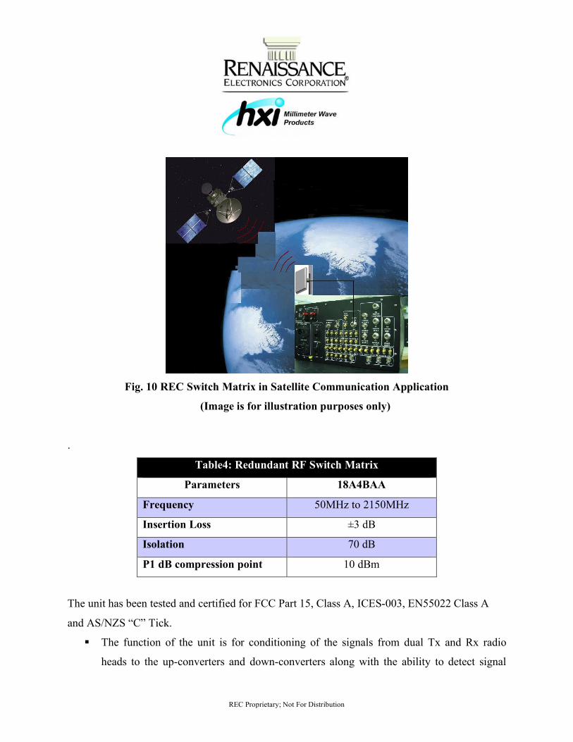
Figure 10 below shows an example of the satellite communication application via redundant
switch matrix. Table 4 lists the electrical specification of the matrix.
REC Proprietary; Not For Distribution
Fig. 10 REC Switch Matrix in Satellite Communication Application
(Image is for illustration purposes only)
.
Table4: Redundant RF Switch Matrix
Parameters 18A4BAA
Frequency 50MHz to 2150MHz
Insertion Loss ±3 dB
Isolation 70 dB
P1 dB compression point 10 dBm
The unit has been tested and certified for FCC Part 15, Class A, ICES-003, EN55022 Class A
and AS/NZS “C” Tick.
The function of the unit is for conditioning of the signals from dual Tx and Rx radio
heads to the up-converters and down-converters along with the ability to detect signal

REC Proprietary; Not For Distribution
dropout thereby switching from the Primary radio to the Secondary radio. Thus the term
Redundant Switch Matrix.
Injection of DC and 10MHz for voltage supplying and monitoring
SUMMARY
As wireless industry expands, there is a growing need of application specific switch matrices.
The design and complexity of such designs varies according to the applications. Based on our
experience, Table 5 lists the following known areas which present our expertise in the areas of
electronics and mechanics. However there are certain unknowns which are customers specific as
listed below. Along with known areas to design, we also have expertise to get the unknown
areas defined according to application and integrate with the complete design.
Known Areas to Design Unknown Areas to Design
System and schematic level design Detail schematic for specific application
Component selection Expected signal levels
Mechanical design Control logistics and interface
Standard control logistics Specs such as vibration/ shock/ temperature
Acceptance test procedure MIL-SPEC requirements
Table 5 Design Considerations

REC Proprietary; Not For Distribution
Twinkle Shah - Renaissance Electronics Corporation 12 Lancaster County Road, Harvard, MA 01451 Phone: (978)-772-7774 Fax: (978)-772-7775