manual york
TRANSCRIPT

8/19/2019 Manual York
http://slidepdf.com/reader/full/manual-york 1/230
LD10950
R-410A
035-21456-000
DUAL CIRCUIT
SINGLE CIRCUIT
YCAL0019, 0022, 0028, 0033, 0043, 0046, 0052, 0056, 0066
AIR-COOLED SCROLL CHILLERS
STYLE E (60 HZ)
15-65 TON
Products are produced at af a c i l i t y w h o s e q u a l i t y -management systems areISO9001 certified.
Issue Date:
March 1, 2012
AIR-COOLED LIQUID CHILLERS
HERMETIC SCROLL
INSTALLATION, OPERATION, MAINTENANCE Supersedes 150.67-NM1 (211) Form 150.67-NM1 (312)

8/19/2019 Manual York
http://slidepdf.com/reader/full/manual-york 2/230JOHNSON CONTROLS2
FORM 150.67-NM1 (312)
This equipment is a relatively complicated apparatus.During installation, operation, maintenance or service,
individuals may be exposed to certain components or
conditions including, but not limited to: refrigerants,
oils, materials under pressure, rotating components,
and both high and low voltage. Each of these items
has the potential, if misused or handled improperly, to
cause bodily injury or death. It is the obligation and re-
sponsibility of operating/service personnel to identify
and recognize these inherent hazards, protect them-
selves, and proceed safely in completing their tasks.
Failure to comply with any of these requirements could
result in serious damage to the equipment and the prop-
IMPORTANT!READ BEFORE PROCEEDING!
GENERAL SAFETY GUIDELINES
erty in which it is situated, as well as severe personalinjury or death to themselves and people at the site.
This document is intended for use by owner-authorized
operating/service personnel. It is expected that this in-
dividual possesses independent training that will en-
able them to perform their assigned tasks properly and
safely. It is essential that, prior to performing any task
on this equipment, this individual shall have read and
understood this document and any referenced mate-
rials. This individual shall also be familiar with and
comply with all applicable governmental standards and
regulations pertaining to the task in question.
SAFETY SYMBOLS
The following symbols are used in this document to alert the reader to areas of potential hazard:
CAUTION identies a hazard which
could lead to damage to the machine,
damage to other equipment and/or
environmental pollution. Usually aninstruction will be given, together with
a brief explanation.
NOTE is used to highlight additional
information which may be helpful to
you.
DANGER indicates an imminently
hazardous situation which, if not
avoided, will result in death or seri -
ous injury.
WARNING indicates a potentially
hazardous situation which, if not
avoided, could result in death or seri -
ous injury.
External wiring, unless specied as an optional connection in the manufacturer’s product
line, is NOT to be connected inside the micro panel cabinet. Devices such as relays, switches,
transducers and controls may NOT be installed inside the panel. NO external wiring is al -
lowed to be run through the micro panel. All wiring must be in accordance with Johnson
Controls published specications and must be performedONLY by qualied Johnson Controls
personnel. Johnson Controls will not be responsible for damages/problems resulting from
improper connections to the controls or application of improper control signals. Failure to
follow this will void the manufacturer’s warranty and cause serious damage to property or
injury to persons.
8/19/2019 Manual York
http://slidepdf.com/reader/full/manual-york 3/230
FORM 150.67-NM1 (312)
3JOHNSON CONTROLS
In complying with Johnson Controls policy for contin-
uous product improvement, the information contained
in this document is subject to change without notice.
While Johnson Controls makes no commitment to up-
date or provide current information automatically to
the manual owner, that information, if applicable, can be obtained by contacting the nearest Johnson Controls
Engineered Systems Service office.
This manual contains installation, op-
eration and maintenance instructions
for both single and dual refrigerant
circuit models. If your unit is a single
circuit model (YCAL0019-0033) ,
disregard references to “System 2”
which may appear in this manual. Any
references to Sys 2 are applicable to
YCAL0043-0066 models.
It is the responsibility of operating/service personnel to
verify the applicability of these documents to the equip-
ment in question. If there is any question in the mind
of operating/service personnel as to the applicability of
these documents, then prior to working on the equip-
ment, they should verify with the owner whether theequipment has been modified and if current literature
is available.
CHANGEABILITY OF THIS DOCUMENT
SINGLE CIRCUIT AND DUAL CIRCUIT MODELS

8/19/2019 Manual York
http://slidepdf.com/reader/full/manual-york 4/230JOHNSON CONTROLS4
FORM 150.67-NM1 (312)
THIS PAGE INTENTIONALLY LEFT BLANK

8/19/2019 Manual York
http://slidepdf.com/reader/full/manual-york 5/230
FORM 150.67-NM1 (312)
5JOHNSON CONTROLS
TABLE OF CONTENTS
SECTION 1 – GENERAL CHILLER INFORMATION AND SAFETY .......................................................................15
INTRODUCTION ............................................................................................................................................15
WARRANTY ...................................................................................................................................................15
SAFETY..........................................................................................................................................................15
Standards for Safety ..............................................................................................................................15
Responsibility for Safety ........................................................................................................................16
ABOUT THIS MANUAL ..................................................................................................................................16
MISUSE OF EQUIPMENT .............................................................................................................................16
Suitability for Application .......................................................................................................................16
Structural Support .................................................................................................................................16
Mechanical Strength .............................................................................................................................16
General Access .....................................................................................................................................16
Pressure Systems .................................................................................................................................16
Electrical ................................................................................................................................................17
Rotating Parts ........................................................................................................................................17
Sharp Edges ..........................................................................................................................................17
Refrigerants and Oils .............................................................................................................................17
High Temperature and Pressure Cleaning ............................................................................................17Emergency Shutdown ...........................................................................................................................17
SECTION 2 – PRODUCT DESCRIPTION ..............................................................................................................19
INTRODUCTION ............................................................................................................................................19
GENERAL SYSTEM DESCRIPTION .............................................................................................................19
Compressors .........................................................................................................................................19
Evaporator (Heat Exchanger) ................................................................................................................19
Condenser .............................................................................................................................................20
Coils ...............................................................................................................................................20
Low Sound Fans ............................................................................................................................20
Motors ............................................................................................................................................20
MILLENIUM CONTROL CENTER ..................................................................................................................20
Display/Print ..........................................................................................................................................20Entry ......................................................................................................................................................20
Setpoints ...............................................................................................................................................20
Unit ........................................................................................................................................................20
Unit On/Off Switch .................................................................................................................................21
COMMUNICATIONS ......................................................................................................................................21
POWER PANEL .............................................................................................................................................21
ACCESSORIES AND OPTIONS ....................................................................................................................22
Power Options .......................................................................................................................................22
Compressor Power Connection .....................................................................................................22
Single-Point Supply Terminal Block ..............................................................................................22
Single-Point Non-Fused Disconnect Switch ..................................................................................22
Single-Point Circuit Breaker ...........................................................................................................22Control Transformer .......................................................................................................................22
Power Factor Correction Capacitors .............................................................................................22
Control Options .....................................................................................................................................22
Ambient Kit (Low) ...........................................................................................................................22
Ambient Kit (High) ..........................................................................................................................22
Building Automation System Interface ...........................................................................................22
Language LCD And Keypad Display..............................................................................................22
Discharge Pressure Transducers And Readout Capability ...........................................................22
Suction Pressure Transducers .......................................................................................................23
Motor Current Module ....................................................................................................................23
Multi-Unit Sequencing ....................................................................................................................23

8/19/2019 Manual York
http://slidepdf.com/reader/full/manual-york 6/230JOHNSON CONTROLS6
FORM 150.67-NM1 (312)
TABLE OF CONTENTS (CONT’D)
Compressor, Piping, Evaporator Options ..............................................................................................23
Low Temperature Brine ..................................................................................................................23
Chicago Code Relief Valves ..........................................................................................................23
Service Isolation Valve ...................................................................................................................23
Hot Gas By-Pass ...........................................................................................................................23
Heat Exchanger 300 PSIG (21 BARG) DWP Waterside................................................................23
Flanges (ANSI/AWWA C-606 Couplings Type) ..............................................................................23Flow Switch ....................................................................................................................................23
150 PSIG (10.5 BARG) DWP ........................................................................................................23
300 PSIG (21 BARG) DWP ...........................................................................................................23
Differential Pressure Switch ...........................................................................................................23
Condenser And Cabinet Options ...........................................................................................................23
Pre-Coated Fin Condenser Coils ...................................................................................................23
Post-Coated Dipped Condenser Coils ...........................................................................................24
Copper Fin Condenser Coils..........................................................................................................24
Enclosure Panels (Unit) .................................................................................................................24
Louvered Panels (Full Unit) ...........................................................................................................24
Sound Reduction / Attenuation Options ................................................................................................24
Vibration Isolators ..........................................................................................................................24UNIT COMPONENTS YCAL0019 - 0033 .......................................................................................................25
CONTROL - POWER PANEL COMPONENTS YCAL0019-0033 ..................................................................26
UNIT COMPONENTS - YCAL0043 – 0066 ....................................................................................................27
CONTROL / POWER PANEL COMPONENTS - YCAL0043 – 0066 ..............................................................28
PRODUCT IDENTIFICATION NUMBER (PIN) .............................................................................................. 29
BASIC UNIT NOMENCLATURE ....................................................................................................................29
REFRIGERANT FLOW DIAGRAM.................................................................................................................34
SECTION 3 – HANDLING AND STORAGE ............................................................................................................35
DELIVERY AND STORAGE ...........................................................................................................................35
INSPECTION .................................................................................................................................................35
MOVING THE CHILLER (YCAL0043 – 0066 DUAL SYSTEM ONLY) ...........................................................35
Lifting Weights .......................................................................................................................................35
MOVING THE CHILLER (YCAL0019 – 0033 SINGLE CIRCUIT ONLY) .......................................................35
UNIT RIGGING...............................................................................................................................................36
Lifting Weights .......................................................................................................................................36
SECTION 4 – INSTALLATION ................................................................................................................................39
INSTALLATION CHECKLIST .........................................................................................................................39
HANDLING .....................................................................................................................................................39
INSPECTION .................................................................................................................................................39
LOCATION AND CLEARANCES.................................................................................................................... 39
Foundation ............................................................................................................................................39
Ground Level Locations ........................................................................................................................39
Rooftop Locations .................................................................................................................................40Noise Sensitive Locations .....................................................................................................................40
SPRING ISOLATORS (OPTIONAL) ............................................................................................................... 40
COMPRESSOR MOUNTING .........................................................................................................................40
REMOTE COOLER OPTION .........................................................................................................................40
CHILLED LIQUID PIPING ..............................................................................................................................40
PIPEWORK ARRANGEMENT .......................................................................................................................41
DUCT WORK CONNECTION .......................................................................................................................41
General Requirements .........................................................................................................................41
WIRING ..........................................................................................................................................................41
Field Wiring ...........................................................................................................................................41
Evaporator Pump Start Contacts ...........................................................................................................42

8/19/2019 Manual York
http://slidepdf.com/reader/full/manual-york 7/230
FORM 150.67-NM1 (312)
7JOHNSON CONTROLS
System Run Contacts ............................................................................................................................42
Alarm Status Contacts ...........................................................................................................................42
Remote Start/Stop Contacts ..................................................................................................................42
Remote Emergency Cutoff ....................................................................................................................42
Remote Temp Reset Input .....................................................................................................................42
Load Limit Input .....................................................................................................................................42
Flow Switch Input ..................................................................................................................................42COMPRESSOR HEATERS ............................................................................................................................ 42
RELIEF VALVES ............................................................................................................................................43
HIGH PRESSURE CUTOUT ..........................................................................................................................43
CONTROL WIRING ........................................................................................................................................45
SECTION 5 – TECHNICAL DATA ...........................................................................................................................47
OPERATIONAL LIMITATIONS (ENGLISH) ....................................................................................................47
Voltage Limitations ................................................................................................................................47
OPERATIONAL LIMITATIONS (SI) ................................................................................................................50
Voltage Limitations ................................................................................................................................50
PHYSICAL DATA (ENGLISH) .........................................................................................................................53
ELECTRICAL DATA (ENGLISH) ....................................................................................................................54ELECTRICAL NOTES AND LEGEND ............................................................................................................59
CONTROL WIRING DIAGRAMS ...................................................................................................................60
POWER OPTIONS CONNECTION DIAGRAMS ...........................................................................................72
CONNECTION WIRING DIAGRAMS .............................................................................................................84
DIMENSIONS (ENGLISH) .............................................................................................................................96
TECHNICAL DATA – CLEARANCES ...........................................................................................................132
ISOLATORS .................................................................................................................................................133
General ................................................................................................................................................133
ISOLATOR LOCATIONS ..............................................................................................................................133
Weight Distribution and Isolator Mounting Positions YCAL0019 – 0033
(Without Pump Package Option) .........................................................................................................133
General ........................................................................................................................................135WEIGHT DISTRIBUTION AND ISOLATOR MOUNTING POSITIONS YCAL0043 – 0066 ..........................135
ISOLATOR DETAILS - UNITS SHIPPED ON OR AFTER JUNE 15, 2008 ..................................................136
ISOLATOR DETAILS - UNITS SHIPPED BEFORE JUNE 15, 2008 ............................................................142
SECTION 6 – COMMISSIONING..........................................................................................................................147
COMMISSIONING .......................................................................................................................................147
PREPARATION – POWER OFF ..................................................................................................................147
Inspection ...........................................................................................................................................147
Refrigerant Charge ..............................................................................................................................147
Service and Oil Line Valves .................................................................................................................147
Compressor Oil ...................................................................................................................................147
Fans ...................................................................................................................................................147
Isolation / Protection ............................................................................................................................147
Control Panel .......................................................................................................................................147
Power Connections .............................................................................................................................147
Grounding ............................................................................................................................................147
Supply Voltage ....................................................................................................................................148
PREPARATION – POWER ON ....................................................................................................................148
Switch Settings ....................................................................................................................................148
Compressor Heaters ...........................................................................................................................148
Water System ......................................................................................................................................148
Flow Switch .........................................................................................................................................148
Temperature Sensor(s) ........................................................................................................................148
TABLE OF CONTENTS (CONT’D)

8/19/2019 Manual York
http://slidepdf.com/reader/full/manual-york 8/230JOHNSON CONTROLS8
FORM 150.67-NM1 (312)
EQUIPMENT START-UP CHECKLIST ......................................................................................................... 149
Checking The Syste m Prior To Initial Start .........................................................................................149
Unit Checks ..................................................................................................................................149
Compressor Heaters ...........................................................................................................................149
Panel Checks ......................................................................................................................................149
CHECKING SUPERHEAT AND SUBCOOLING ..........................................................................................150
LEAK CHECKING ........................................................................................................................................151UNIT OPERATING SEQUENCE .................................................................................................................. 152
SECTION 7 – UNIT CONTROLS ..........................................................................................................................153
Introduction ..........................................................................................................................................153
IPU II and I/O Boards ..........................................................................................................................153
Unit Switch ..........................................................................................................................................154
Display .................................................................................................................................................154
Keypad ................................................................................................................................................154
Battery Back-up ...................................................................................................................................154
Transformer ........................................................................................................................................154
Single System Select and Programming # of Compressors ...............................................................154
STATUS KEY ................................................................................................................................................ 155Unit Status ...........................................................................................................................................155
General Status Messages ...................................................................................................................155
Fault Safety Status Messages .............................................................................................................156
System Safeties ...........................................................................................................................157
Unit Safeties .................................................................................................................................158
Unit Warning ........................................................................................................................................158
Status Key Messages ..........................................................................................................................160
DISPLAY/PRINT KEYS ................................................................................................................................161
Oper Data Key .....................................................................................................................................161
Oper Data Quick Reference List .........................................................................................................164
Print Key ..............................................................................................................................................164
Operating Data Printout .......................................................................................................................164History Printout ....................................................................................................................................165
History Displays ...................................................................................................................................166
Software Version .................................................................................................................................168
ENTRY KEYS ...............................................................................................................................................169
Up and Down Arrow Keys ...................................................................................................................169
Enter/Adv Key .....................................................................................................................................169
SETPOINTS KEYS ......................................................................................................................................170
Cooling Setpoints ................................................................................................................................170
Leaving Chilled Liquid Control .............................................................................................................170
Return Chilled Liquid Control ..............................................................................................................171
Remote Setpoint Control .....................................................................................................................171
SCHEDULE/ADVANCE DAY KEY................................................................................................................ 172PROGRAM KEY ...........................................................................................................................................173
Unit Trip Volts ......................................................................................................................................175
System Trip Volts .................................................................................................................................175
UNIT KEYS ..................................................................................................................................................177
Options Key .........................................................................................................................................177
Option 1 – Language ...................................................................................................................177
Option 2 – System Switches: (two system units only) .................................................................177
Option 3 – Chilled Liquid Cooling Type: .......................................................................................177
Option 4 – Ambient Control Type .................................................................................................178
Option 5 – Local/Remote Control Type ........................................................................................178
Option 6 – Unit Control Mode ......................................................................................................178
TABLE OF CONTENTS (CONT’D)

8/19/2019 Manual York
http://slidepdf.com/reader/full/manual-york 9/230
FORM 150.67-NM1 (312)
9JOHNSON CONTROLS
Option 7 – Display Units ..............................................................................................................178
Option 8 – Lead/Lag Type ...........................................................................................................178
Option 9 – Condenser Fan Control Mode ...................................................................................179
Option 10 – Manual Override Mode .............................................................................................179
Option 11 – Current Feedback Options Installed: ........................................................................179
Option 12 – Power Fail Restart ....................................................................................................179
Option 13 – Soft Start Enable/Disable .........................................................................................179
Option 14 – Unit Type ..................................................................................................................179
Option 15 – Refrigerant Type .......................................................................................................180
Option 16 – Expansion Valve Type ..............................................................................................180
Option 17 – Flash Card Update ...................................................................................................180
Option 18 – Remote Temperature Reset .....................................................................................180
Option 19 – Pump Control ...........................................................................................................181
Option 20 – Pump Selection ........................................................................................................181
CLOCK .........................................................................................................................................................181
SECTION 8 – UNIT OPERATION .........................................................................................................................183
CAPACITY CONTROL .................................................................................................................................183
SUCTION PRESSURE LIMIT CONTROLS .................................................................................................183
DISCHARGE PRESSURE LIMIT CONTROLS ............................................................................................183
LEAVING CHILLED LIQUID CONTROL ......................................................................................................183
LEAVING CHILLED LIQUID CONTROL OVERRIDE TO REDUCE CYCLING ............................................ 184
LEAVING CHILLED LIQUID SYSTEM LEAD/LAG AND COMPRESSOR SEQUENCING ..........................184
RETURN CHILLED LIQUID CONTROL .......................................................................................................185
RETURN CHILLLED LIQUID SYSTEM LEAD/LAG AND COMPRESSOR SEQUENCING ........................185
ANTI-RECYCLE TIMER ...............................................................................................................................186
ANTI-COINCIDENCE TIMER .......................................................................................................................186
EVAPORATOR PUMP CONTROL AND YORK HYDRO KIT PUMP CONTROL .........................................187
EVAPORATOR HEATER CONTROL ...........................................................................................................187
PUMPDOWN CONTROL .............................................................................................................................187
STANDARD CONDENSER FAN CONTROL ...............................................................................................187
General ................................................................................................................................................190Potentiometer Conguration ................................................................................................................19
LOW AMBIENT FAN CONTROL OPTION ...................................................................................................190
Wiring ..................................................................................................................................................191
PROGRAMMING - YCAL0019 – 0028 .........................................................................................................192
YCAL0033 Low Ambient Fan Control Option ......................................................................................192
General ................................................................................................................................................192
CONFIGURATION (JUMPERS AND POTENTIOMETERS) ........................................................................193
Wiring ..................................................................................................................................................194
YCAL0033 PROGRAMMING .......................................................................................................................195
YCAL0043 – 0066 LOW AMBIENT FAN CONTROL OPTION .....................................................................196
General ................................................................................................................................................196
CONFIGURATION (JUMPERS AND POTENTIOMETERS) ........................................................................197Wiring ..................................................................................................................................................197
PROGRAMMING ........................................................................................................................................198
LOAD LIMITING ...........................................................................................................................................200
COMPRESSOR RUN STATUS ....................................................................................................................200
ALARM STATUS ..........................................................................................................................................200
BAS/EMS TEMPERATURE RESET USING
A VOLTAGE OR CURRENT SIGNAL ...........................................................................................................200
SECTION 9 – SERVICE AND TROUBLESHOOTING ..........................................................................................203
CLEARING HISTORY BUFFERS ................................................................................................................203
SERVICE MODE ..........................................................................................................................................203
TABLE OF CONTENTS (CONT’D)

8/19/2019 Manual York
http://slidepdf.com/reader/full/manual-york 10/230JOHNSON CONTROLS10
FORM 150.67-NM1 (312)
SERVICE MODE – OUTPUTS .....................................................................................................................203
SERVICE MODE – CHILLER CONFIGURATION ........................................................................................204
SERVICE MODE – ANALOG AND DIGITAL INPUTS ..................................................................................204
CONTROL INPUTS/OUTPUTS ....................................................................................................................205
CHECKING INPUTS AND OUTPUTS ..........................................................................................................207
Digital Inputs ........................................................................................................................................207
Analog Inputs – Temperature ..............................................................................................................207
Outside Air Sensor ..............................................................................................................................207
Liquid and Refrigerant Sensor Test Points .........................................................................................208
Entering Chilled Liquid Sensor .....................................................................................................208
Leaving Chilled Liquid Temperature Sensor ................................................................................208
Analog Inputs – Pressure ....................................................................................................................209
System 1 Discharge Transducer ..................................................................................................209
System 2 Discharge Transducer ..................................................................................................209
System 1 Suction Transducer ......................................................................................................210
System 2 Suction Transducer ......................................................................................................210
Digital Outputs .....................................................................................................................................210
OPTIONAL PRINTER INSTALLATION......................................................................................................... 211
Parts ....................................................................................................................................................211
Assembly and Wiring ........................................................................................................................... 211
Obtaining a Printout ............................................................................................................................. 211
SECTION 10 – MAINTENANCE ...........................................................................................................................215
IMPORTANT .................................................................................................................................................215
COMPRESSORS .........................................................................................................................................215
Oil Level Check ...................................................................................................................................215
Oil Analysis ..........................................................................................................................................215
CONDENSER FAN MOTORS ......................................................................................................................215
CONDENSER COILS ...................................................................................................................................215
OPERATING PARAMETERS .......................................................................................................................215
ON-BOARD BATTERY BACK-UP ................................................................................................................215PLATE AND FRAME HEAT EXCHANGER (EVAPORATOR) HEATER .......................................................215
OVERALL UNIT INSPECTION .....................................................................................................................216
Received Data (Control Data) .............................................................................................................216
Transmitted Data .................................................................................................................................216
BACNET, MODBUS AND YORKTALK 2 COMMUNICATIONS ....................................................................217
BACnet and Modbus Communications ...............................................................................................220
Analog Write Points .....................................................................................................................220
Binary Write Points ......................................................................................................................220
Analog Read Only Points .............................................................................................................220
Binary Monitor Only Points ..........................................................................................................220
Communications Data Map Notes: ..............................................................................................220
Yorktalk 2 Communications .................................................................................................................224Received Data (Control Data) ......................................................................................................224
Transmitted Data..........................................................................................................................224
TEMPERATURE CONVERSION CHART .................................................................................................... 228
R410-A PRESSURE TEMPERATURE CHART............................................................................................229
Adding Refrigerant Charge After Commissioning ................................................................................229
TABLE OF CONTENTS (CONT’D)

8/19/2019 Manual York
http://slidepdf.com/reader/full/manual-york 11/230
FORM 150.67-NM1 (312)
11JOHNSON CONTROLS
LIST OF FIGURES
FIGURE 1 - YCAL AIR-COOLED SCROLL CHILLERS ..........................................................................................19
FIGURE 2 - UNIT COMPONENTS SINGLE SYSTEM UNITS ................................................................................25
FIGURE 3 - CONTROL/POWER PANEL COMPONENTS SINGLE SYSTEM UNITS............................................2
FIGURE 4 - UNIT COMPONENTS DUAL SYSTEM UNITS....................................................................................27
FIGURE 5 - CONTROL/POWER PANEL COMPONENTS DUAL SYSTEM UNITS ...............................................28
FIGURE 6 - REFRIGERANT FLOW DIAGRAM ......................................................................................................34
FIGURE 7 - UNIT RIGGING/LIFTING (YCAL0019 – 0033 SINGLE CIRCUIT MODELS ONLY) ............................36FIGURE 8 - UNIT RIGGING/LIFTING (YCAL0043- 0066 DUAL CIRCUIT MODELS) ............................................37
FIGURE 9 - CHILLED LIQUID SYSTEM .................................................................................................................41
FIGURE 10 - SINGLE-POINT SUPPLY CONNECTION – TERMINAL BLOCK, NON-FUSED
DISCONNECT SWITCH OR CIRCUIT BREAKER (0043 – 0066) ....................................................44
FIGURE 11 - CONTROL WIRING ...........................................................................................................................45
FIGURE 12 - CONTROL WIRING DIAGRAM, SINGLE CIRCUIT, IPU II ................................................................60
FIGURE 13 - CONTROL WIRING DIAGRAM, SINGLE CIRCUIT, IPU II ................................................................63
FIGURE 14 - CONTROL WIRING DIAGRAM, DUAL CIRCUIT, IPU II ...................................................................64
FIGURE 15 - CONTROL WIRING DIAGRAM, DUAL CIRCUIT, IPU II ...................................................................66
FIGURE 16 - CONTROL WIRING DIAGRAM, DETAILS, SINGLE CIRCUIT .......................................................... 69
FIGURE 17 - CONTROL WIRING DIAGRAM, DETAILS, DUAL CIRCUIT .............................................................70
FIGURE 18 - POWER WIRING, SINGLE CIRCUIT ................................................................................................72
FIGURE 19 - POWER WIRING, SINGLE CIRCUIT ................................................................................................74FIGURE 20 - POWER WIRING, SINGLE CIRCUIT ................................................................................................76
FIGURE 21 - POWER WIRING, SINGLE CIRCUIT ................................................................................................78
FIGURE 22 - POWER WIRING, DUAL CIRCUIT ....................................................................................................81
FIGURE 23 - POWER WIRING, DUAL CIRCUIT ....................................................................................................82
FIGURE 24 - CONNECTION WIRING, SINGLE CIRCUIT .....................................................................................84
FIGURE 25 - CONNECTION WIRING, SINGLE CIRCUIT .....................................................................................86
FIGURE 26 - CONNECTION WIRING, SINGLE CIRCUIT .....................................................................................88
FIGURE 27 - CONNECTION WIRING, SINGLE CIRCUIT .....................................................................................90
FIGURE 28 - CONNECTION WIRING, DUAL CIRCUIT .........................................................................................93
FIGURE 29 - CONNECTION WIRING, DUAL CIRCUIT .........................................................................................94
FIGURE 30 - UNIT CLEARANCES – ALL MODELS .............................................................................................132
FIGURE 31 - ONE INCH DEFLECTION SPRING ISOLATOR CROSS-REFERENCE ........................................136
FIGURE 32 - ONE INCH DEFLECTION SPRING ISOLATORS INSTALLATION INSTRUCTIONS .....................137
FIGURE 33 - DURULENE ISOLATOR CROSS-REFERENCE .............................................................................138
FIGURE 34 - INSTALLATION OF DURULENE VIBRATION ISOLATORS ...........................................................139
FIGURE 35 - TWO INCH DEFLECTION SEISMIC ISOLATOR CROSS-REFERENCE .......................................140
FIGURE 36 - SEISMIC ISOLATOR INSTALLATION AND ADJUSTMENT ............................................................141
FIGURE 37 - ONE INCH DEFLECTION SPRING ISOLATOR CROSS-REFERENCE (CIP-X) ...........................142
FIGURE 38 - NEOPRENE ISOLATOR CROSS-REFERENCE ............................................................................144
FIGURE 39 - TWO INCH DEFLECTION, SEISMIC SPRING ISOLATOR CROSS-REFERENCE .......................145
FIGURE 40 - SLRS SEISMIC ISOLATOR INSTALLATION AND ADJUSTMENT .................................................146
FIGURE 41 - LEAVING WATER TEMPERATURE CONTROL EXAMPLE ...........................................................184
FIGURE 42 - SETPOINT ADJUST ........................................................................................................................184
FIGURE 43 - YCAL0019 – YCAL0033 FAN LOCATION (TYPICAL).....................................................................188
FIGURE 44 - CAL0043 – YCAL0066 FAN LOCATION (TYPICAL) .......................................................................189FIGURE 45 - TYPICAL VFD LOCATION ...............................................................................................................190
FIGURE 46 - LIQUID LINE SENSING BULB LOCATION .....................................................................................190
FIGURE 47 - POTENTIOMETER SETTINGS .......................................................................................................190
FIGURE 48 - WIRING ...........................................................................................................................................191
FIGURE 49 - TYPICAL VFD ENCLOSURE LOCATIONS .....................................................................................192
FIGURE 50 - TYPICAL VFD ENCLOSURE CONFIGURATIONS .........................................................................193
FIGURE 51 - POTENTIOMETER SETTINGS .......................................................................................................194
FIGURE 52 - INVERTER POWER WIRING SCHEMATIC ....................................................................................194
FIGURE 53 - INVERTER WIRING ........................................................................................................................195
FIGURE 54 - TYPICAL VFD ENCLOSURE LOCATIONS .....................................................................................196
FIGURE 55 - TYPICAL VFD ENCLOSURE CONFIGURATIONS .........................................................................197
FIGURE 56 - INVERTER POWER WIRING SC ....................................................................................................198

8/19/2019 Manual York
http://slidepdf.com/reader/full/manual-york 12/230JOHNSON CONTROLS12
FORM 150.67-NM1 (312)
LIST OF FIGURES (CONT’D)
FIGURE 57 - POTENTIOMETER SETTINGS .......................................................................................................198
FIGURE 58 - INVERTER WIRING .......................................................................................................................199
FIGURE 59 - MICROBOARD LAYOUT .................................................................................................................206
FIGURE 60 - /O BOARD RELAY CONTACT ARCHITECTURE ............................................................................210
FIGURE 61 - PRINTER TO MICROBOARD ELECTRICAL CONNECTIONS ....................................................... 211
FIGURE 62 - MICRO PANEL CONNECTIONS .....................................................................................................218

8/19/2019 Manual York
http://slidepdf.com/reader/full/manual-york 13/230
FORM 150.67-NM1 (312)
13JOHNSON CONTROLS
LIST OF TABLES
TABLE 1 - TEMPERATURES AND FLOWS ................................................................................................................47
TABLE 2 - VOLTAGE LIMITATIONS ............................................................................................................................47
TABLE 3 - TEMPERATURES AND FLOWS (SI) .........................................................................................................50
TABLE 4 - VOLTAGE LIMITATIONS ............................................................................................................................50
TABLE 5 - ETHYLENE AND PROPOLYNE GLYCOL CORRECTION FACTORS ......................................................50
TABLE 6 - PHYSICAL DATA (ENGLISH) ....................................................................................................................53
TABLE 7 - ELECTRICAL DATA (ENGLISH) ................................................................................................................54TABLE 8 - MICRO PANEL POWER SUPPLY .............................................................................................................58
TABLE 9 - VOLTAGE RANGE .....................................................................................................................................58
TABLE 10 - SETPOINTS ENTRY LIST .....................................................................................................................150
TABLE 11 - STATUS KEY MESSAGES QUICK REFERENCE LIST ........................................................................160
TABLE 12 - OPERATION DATA ................................................................................................................................164
TABLE 13 - COOLING SETPOINTS, PROGRAMMABLE LIMITS AND DEFAULTS ................................................171
TABLE 14 - PROGRAM KEY LIMITS AND DEFAULT ...............................................................................................173
TABLE 15 - SETPOINTS QUICK REFERENCE LIST ...............................................................................................176
TABLE 16 - UNIT KEYS OPTIONS PROGRAMMING QUICK REFERENCE LIST ..................................................182
TABLE 17 - SAMPLE COMPRESSOR STAGING FOR RETURN WATER CONTROL ............................................185
TABLE 18 - RETURN CHILLED LIQUID CONTROL FOR 4 COMPRESSORS (6 STEPS) .....................................186
TABLE 19 - RETURN CHILLED LIQUID CONTROL FOR 4 COMPRESSORS (6 STEPS) .....................................186
TABLE 20 - YCAL0019 – YCAL0033 CONDENSER FAN CONTROL USING DISCHARGE PRESSURE ..............188TABLE 21 - YCAL0019 – YCAL0033 CONDENSER FAN CONTROL USING DISCHARGE PRESSURE ONLY ....188
TABLE 22 - YCAL0043 – YCAL0066 CONDENSER FAN CONTROL USING DISCHARGE PRESSURE. .............189
TABLE 23 - YCAL0043 – YCAL0066 CONDENSER FAN CONTROL USING DISCHARGE PRESSURE ONLY ....189
TABLE 24 - YCAL0019 – 0028 VFD LOW AMBIENT OPTION – CONDENSER FAN CONTROL OPERATION......192
TABLE 25 - VFD JUMPERS ......................................................................................................................................193
TABLE 26 - YCAL033 VFD LOW AMBIENT OPTION – CONDENSER FAN CONTROL OPERATION....................195
TABLE 27 - VFD JUMPERS ......................................................................................................................................197
TABLE 28 - YCAL0043-0066 VFD LOW AMBIENT OPTION – CONDENSER FAN CONTROL OPERATION ........199
TABLE 29 - COMPRESSOR OPERATION –LOAD LIMITING ..................................................................................200
TABLE 30 - I/O DIGITAL INPUTS ..............................................................................................................................205
TABLE 31 - I/O DIGITAL OUTPUTS ..........................................................................................................................205
TABLE 32 - I/O ANALOG INPUTS ............................................................................................................................205
TABLE 33 - I/O ANALOG OUTPUTS ........................................................................................................................205
TABLE 34 - OUTDOOR AIR SENSOR TEMPERATURE/VOLTAGE / CORRELATION ............................................207
TABLE 35 - ENTERING/LEAVING CHILLED LIQUID TEMPERATURE SENSOR ...................................................208
TABLE 36 - PRESSURE TRANSDUCERS ...............................................................................................................209
TABLE 37 - TROUBLESHOOTING ...........................................................................................................................212
TABLE 38 - MINIMUM, MAXIMUM AND DEFAULT VALUES ...................................................................................218
TABLE 39 - VALUES REQUIRED FOR BAS COMMUNICATION.............................................................................219
TABLE 40 - REAL TIME ERROR NUMBERS ...........................................................................................................219
TABLE 41 - BACNET AND MODBUS COMMUNICATIONS DATA MAP...................................................................221
TABLE 42 - YORKTALK 2 COMMUNICATIONS DATA MAP ....................................................................................225

8/19/2019 Manual York
http://slidepdf.com/reader/full/manual-york 14/230JOHNSON CONTROLS14
FORM 150.67-NM1 (312)
THIS PAGE INTENTIONALLY LEFT BLANK

8/19/2019 Manual York
http://slidepdf.com/reader/full/manual-york 15/230
FORM 150.67-NM1 (312)
15JOHNSON CONTROLS
SECTION 1 – GENERAL CHILLER INFORMATION AND SAFETY
INTRODUCTION
YORK YCAL0019-0066 (15-65 ton, 53-218Kw) chill-
ers are manufactured to the highest design and con-
struction standards to ensure high performance, reli-
ability and adaptability to all types of air conditioninginstallations.
The unit is intended for cooling water or glycol solu-
tions and is not suitable for purposes other than those
specified in this manual.
This manual contains all the information required for
correct installation and commissioning of the unit, to-
gether with operating and maintenance instructions.
The manuals should be read thoroughly before at-
tempting to operate or service the unit.
All procedures detailed in the manuals, including in-stallation, commissioning and maintenance tasks must
only be performed by suitably trained and qualified
personnel.
The manufacturer will not be liable for any injury or
damage caused by incorrect installation, commission-
ing, operation or maintenance resulting from a failure
to follow the procedures and instructions detailed in
the manuals.
WARRANTY
Johnson Controls warrants all equipment and materials
against defects in workmanship and materials for a pe-
riod of eighteen months from date of shipment, unless
labor or extended warranty has been purchased as part
of the contract.
The warranty is limited to parts only replacement and
shipping of any faulty part, or sub-assembly, which has
failed due to poor quality or manufacturing errors. All
claims must be supported by evidence that the failure
has occurred within the warranty period, and that the
unit has been operated within the designed parametersspecified.
All warranty claims must specify the unit model, serial
number, order number and run hours/starts. Model and
serial number information is printed on the unit identi-
fication plate.
The unit warranty will be void if any modification to
the unit is carried out without prior written approval
from Johnson Controls.
For warranty purposes, the following conditions must
be satisfied:
• The initial start of the unit must be carried out
by trained personnel from an Authorized John
son Controls Service Center (see CommissioningPage 147).
• Only genuine YORK approved spare parts, oils
coolants, and refrigerants must be used.
• All the scheduled maintenance operations detailed
in this manual must be performed at the specied
times by suitably trained and qualied personnel
(see Maintenance Section, Page 215).
• Failure to satisfy any of these conditions will au-
tomatically void the warranty (see Warranty Pol-
icy).
SAFETY
Standards for Safety
YCAL chillers are designed and built within an ISO
9002 accredited design and manufacturing organiza-
tion. The chillers comply with the applicable sections
of the following Standards and Codes:
• ANSI/ASHRAE Standard 15 - Safety Code for
Mechanical Refrigeration.
• ANSI/NFPA Standard 70 - National Electrica
Code (N.E.C.).
• ASME Boiler and Pressure Vessel Code- Section
VIII Division 1.
• ARI Standard 550/590-98- Water Chilling Pack-
ages Using the Vapor Compression Cycle.
• ASHRAE 90.1- Energy Efciency Compliance.
• ARI 370- Sound Rating of Large Outdoor Refrig-
eration and Air Conditioning Equipment.
• Conform to Intertek Testing Services, formerly
ETL, for construction of chillers and provide
ETL/cETL listing label.
• Manufactured in facility registered to ISO 9002.
• OSHA – Occupational Safety and Health Act.
In addition, the chillers conform to Underwriters Labo-
ratories (U.L.) for construction of chillers and provide
U.L./cU.L. Listing Label.

8/19/2019 Manual York
http://slidepdf.com/reader/full/manual-york 16/230JOHNSON CONTROLS16
FORM 150.67-NM1 (312)
General Chiller Introduction and Safety
Responsibility for Safety
Every care has been taken in the design and manufac-
ture of the unit to ensure compliance with the safety
requirements listed above. However, the individual
operating or working on any machinery is primarily
responsible for:
• Personal safety, safety of other personnel, and themachinery.
• Correct utilization of the machinery in accordance
with the procedures detailed in the manuals.
ABOUT THIS MANUAL
The following terms are used in this document to alert
the reader to areas of potential hazard.
A WARNING is given in this document to identify a
hazard, which could lead to personal injury. Usually an
instruction will be given, together with a brief explana-
tion and the possible result of ignoring the instruction.
A CAUTION identifies a hazard which could lead to
damage to the machine, damage to other equipment
and/or environmental pollution. Usually an instruction
will be given, together with a brief explanation and the
possible result of ignoring the instruction.
A NOTE is used to highlight additional information,
which may be helpful to you but where there are no
special safety implications.
The contents of this manual include suggested best
working practices and procedures. These are issued for
guidance only, and they do not take precedence over
the above stated individual responsibility and/or local
safety regulations.
This manual and any other document supplied with
the unit are the property of Johnson Controls which
reserves all rights. They may not be reproduced, in
whole or in part, without prior written authorization
from an authorized Johnson Controls representative.
MISUSE OF EQUIPMENT
Suitability for Application
The unit is intended for cooling water or glycol solu-
tions and is not suitable for purposes other than those
specified in these instructions. Any use of the equipment
other than its intended use, or operation of the equip-
ment contrary to the relevant procedures may result in
injury to the operator, or damage to the equipment.
The unit must not be operated outside the design pa-
rameters specified in this manual.
Structural Support
Structural support of the unit must be provided as in-
dicated in these instructions. Failure to provide proper
support may result in injury to the operator, or damage
to the equipment and/or building.
Mechanical Strength
The unit is not designed to withstand loads or stresses
from adjacent equipment, pipework or structures. Ad-ditional components must not be mounted on the unit.
Any such extraneous loads may cause structural failure
and may result in injury to the operator, or damage to
the equipment.
General Access
There are a number of areas and features, which may
be a hazard and potentially cause injury when working
on the unit unless suitable safety precautions are taken.
It is important to ensure access to the unit is restricted
to suitably qualified persons who are familiar with the potential hazards and precautions necessary for safe
operation and maintenance of equipment containing
high temperatures, pressures and voltages.
Pressure Systems
The unit contains refrigerant vapor and liquid under pres-
sure, release of which can be a danger and cause injury.
The user should ensure that care is taken during installa-
tion, operation and maintenance to avoid damage to the

8/19/2019 Manual York
http://slidepdf.com/reader/full/manual-york 17/230
FORM 150.67-NM1 (312)
17JOHNSON CONTROLS
pressure system. No attempt should be made to gain ac-
cess to the component parts of the pressure system other
than by suitably trained and qualified personnel.
Electrical
The unit must be grounded. No installation or main-
tenance work should be attempted on the electrical
equipment without first switching power OFF, isolat-ing and locking-off the power supply. Servicing and
maintenance on live equipment must only be per-
formed by suitably trained and qualified personnel. No
attempt should be made to gain access to the control
panel or electrical enclosures during normal operation
of the unit.
Rotating Parts
Fan guards must be fitted at all times and not removed
unless the power supply has been isolated. If ductwork
is to be fitted, requiring the wire fan guards to be re-moved, alternative safety measures must be taken to
protect against the risk of injury from rotating fans.
Sharp Edges
The fins on the air-cooled condenser coils have sharp
metal edges. Reasonable care should be taken when
working in contact with the coils to avoid the risk of
minor abrasions and lacerations. The use of gloves is
recommended.
Frame rails, brakes, and other components may also
have sharp edges. Reasonable care should be taken
when working in contact with any components to avoid
risk of minor abrasions and lacerations.
Refrigerants and Oils
Refrigerants and oils used in the unit are generally non-
toxic, non-flammable and non-corrosive, and pose nospecial safety hazards. Use of gloves and safety glasses
is, however, recommended when working on the unit
The build up of refrigerant vapor, from a leak for ex-
ample, does pose a risk of asphyxiation in confined or
enclosed spaces and attention should be given to good
ventilation.
High Temperature and Pressure Cleaning
High temperature and pressure cleaning methods
(e.g. steam cleaning) should not be used on any par
of the pressure system as this may cause operation ofthe pressure relief device(s). Detergents and solvents
which may cause corrosion, should also be avoided.
Emergency Shutdown
In case of emergency, the control panel is fitted with a
Unit Switch to stop the unit in an emergency. When op
erated, it removes the low voltage 120VAC electrica
supply from the inverter system, thus shutting down
the unit.

8/19/2019 Manual York
http://slidepdf.com/reader/full/manual-york 18/230JOHNSON CONTROLS18
FORM 150.67-NM1 (312)
THIS PAGE INTENTIONALLY LEFT BLANK

8/19/2019 Manual York
http://slidepdf.com/reader/full/manual-york 19/230
FORM 150.67-NM1 (312)
19JOHNSON CONTROLS
SECTION 2 – PRODUCT DESCRIPTION
INTRODUCTION
YORK Millennium® Air-Cooled Scroll Chillers pro-
vide chilled water for all air conditioning applications
using central station air handling or terminal units. They
are completely self-contained and are designed for out-
door (roof or ground level) installation. Each complete packaged unit includes hermetic scroll compressors, a
liquid cooler, air cooled condenser, a charge of refriger-
ant R-410A and a weather resistant microprocessor con-
trol center, all mounted on a pressed steel base.
The units are completely assembled with all intercon-
necting refrigerant piping and internal wiring, ready for
field installation.
Prior to delivery, the packaged unit is pressure-tested,
evacuated, and fully charged with Refrigerant-R410A
and oil. After assembly, a complete operational test is performed with water flowing through the cooler to as-
sure that the refrigeration circuit operates correctly.
The unit structure is heavy-gauge, galvanized steel. This
galvanized steel is coated with baked-on powder paint,
which, when subjected to ASTM B117 1000 hour, salt
spray testing, yields a minimum ASTM 1654 rating of
“6”. Corrosion resistant wire mesh panels are added to
protect the condenser coil from incidental damage and
restrict unauthorized access to internal components.
Units are designed in accordance with NFPA 70 (Na-
tional Electric Code), ASHRAE/ANSI 15 Safety codefor mechanical refrigeration, ASME, Listed and labeled
with Intertek Testing Services (ETL) and rated in accor-
dance with ARI Standard 550/590-2003.
All exposed power wiring is routed through liquid-
tight, non-metallic conduit.
GENERAL SYSTEM DESCRIPTION
Compressors
The chiller has suction-gas cooled, hermetic, scroll
compressors. The YCAL compressors incorporate a
compliant scroll design in both the axial and radia
direction. All rotating parts are statically and dynami-
cally balanced. A large internal volume and oil res-
ervoir provides greater liquid tolerance. Compressor
crankcase heaters are also included for extra protection
against liquid migration.
Evaporator (Heat Exchanger)
The Brazed Plate Heat Exchanger is equipped with
a heater controlled by the microprocessor. The heat-
er provides freeze protection for the cooler down to
-20 °F (-29 °C) ambient. The cooler is covered with
3/4" (19mm) flexible, closed-cell, foam insulation
(K~0.25).
Brazed plate heat exchangers shall be UL (Underwriters
Laboratories) listed. Installing contractor must include
accommodations in the chilled water piping to allow
proper drainage and venting of the heat exchanger. Wa
ter inlet and outlet connections are grooved for compat-
ibility with factory supplied victaulic connections.
LD1095
Dual Circuit
FIGURE 1 - YCAL AIR-COOLED SCROLL CHILLERS

8/19/2019 Manual York
http://slidepdf.com/reader/full/manual-york 20/230JOHNSON CONTROLS20
FORM 150.67-NM1 (312)
Product Description
The heat exchanger is a brazed plate stainless steel con-
struction, single or dual circuit heat exchanger capable
of refrigerant working pressure of 650 PSIG (3103
kPa) and liquid side pressure of 150 PSIG (1034 kPa)
(Option for 300 PSIG [2068 kPa] available). Each heat
exchanger is covered in 3/4" (19mm) flexible, closed
cell insulation, thermal conductivity of 0.26k ([BTU/
HR-FT2
– °F] /in) maximum.
A strainer with a mesh size between .5 and 1.5 mm (40
mesh) is recommended upstream of the heat exchanger
to prevent clogging.
Condenser
Coils
Fin and tube condenser coils of seamless, internally-
enhanced, high-condensing-coefficient, corrosion re-
sistant copper tubes are arranged in staggered rows,
mechanically expanded into aluminum fins. Integralsubcooling is included. The design working pressure
of the coil is 650 PSIG (45 bar).
Low Sound Fans
The condenser fans are composed of corrosion resis-
tant aluminum hub and glass-fiber reinforced compos-
ite blades molded into a low noise airfoil section. They
are designed for maximum efficiency and are statically
and dynamically balanced for vibration free operation.
They are directly driven by independent motors, and
positioned for vertical air discharge. All blades are
statically and dynamically balanced for vibration-freeoperation. The fan guards are constructed of heavy-
gauge, rust-resistant, PVC coated steel wire.
Motors
The fan motors are Totally Enclosed Air-Over (TEAO),
direct drive, 6 pole, current protected. They feature ball
bearings that are double-sealed and permanently lubri-
cated.
MILLENIUM CONTROL CENTER
All controls are contained in a NEMA 3R/12 (andequivalent to IP55*) cabinet with hinged outer door
and include Liquid Crystal Display (LCD) with Light
Emitting Diode (LED) backlighting for outdoor view-
ing and includes:
• Two display lines
• Twenty characters per line
Display/Print
Color coded 12-button non-tactile keypad with sec-
tions for display and print of typical information:
• Chilled liquid temperatures.
• Ambient temperature.
• System pressures (each circuit).
• Operating hours and starts (each compressor).
• Print calls up to the liquid crystal display.
• Operating data for the systems.
• History of fault shutdown data for up to the last
six fault shutdown conditions.
• An RS-232 port, in conjunction with this press-to-
print button, is provided to permit the capability
of hard copy print-outs via a separate printer (by
others).
Entry
This section is used to enter setpoints or modify system
values.
Setpoints
Updating can be performed to:
• Chilled liquid temperature setpoint and range
• Remote reset temperature range
• Set daily schedule/holiday for start/stop
• Manual override for servicing
• Low and high ambient cutouts
• Number of compressors
• Low liquid temperature cutout
• Low suction pressure cutout
• High discharge pressure cutout
• Anti-recycle timer (compressor start cycle time)
• Anti-coincident timer (delay compressor starts)
Unit
This section is used to:
• Set time
• Set unit options
* Intensity of Protection European Standard
** International Electrotechnical Commission

8/19/2019 Manual York
http://slidepdf.com/reader/full/manual-york 21/230
FORM 150.67-NM1 (312)
21JOHNSON CONTROLS
Unit On/Off Switch
The microprocessor control center is capable of dis-
playing the following:
• Return and leaving liquid temperature
• Low leaving liquid temperature cutout setting
• Low ambient temperature cutout setting
• Outdoor air temperature
• English or Metric data
• Suction pressure cutout setting
• Each system suction pressure
• Discharge pressure (optional)
• Liquid Temperature Reset via a YORK ISN DDC
or Building Automation System (by others) via:
• a pulse width modulated (PWM) input asstandard.
• a 4 to 20 milliamp or 0 to 10 VDC input with
the optional B.A.S. interface option.
• Anti-recycle timer status for each system
• Anti-coincident system start timer condition
• Compressor run status
• No cooling load condition
• Day, date and time
• Daily start/stop times
• Holiday status
• Automatic or manual system lead/lag control
• Lead system denition
• Compressor starts and operating hours
(each compressor)
• Status of hot gas valves, evaporator heater and fan
operation
* Intensity of Protection European Standard
** International Electrotechnical Commission
• Run permissive status
• Number of compressors running
• Liquid solenoid valve status
• Load and unload timer status
• Water pump status
Provisions are included for:
• Pumpdown at shutdown.
• Optional remote chilled water temperature reset.
• Two steps of demand load limiting from an exter-
nal building automation system.
Unit alarm contacts are standard.
The operating program is stored in non-volatile mem-
ory (EPROM) to eliminate chiller failure due to AC
powered failure/battery discharge. Programmed set points are retained in lithium battery-backed RTC
memory for 5 years minimum.
COMMUNICATIONS
• Native communication capability for BACne
(MS/TP) and Modbus
• Optional communication available for N2 and
LON via eLink option
POWER PANEL
Each panel contains:
• Compressor power terminals
• Compressor motor starting contactors per l.E.C.**
• Control power terminals to accept incoming for
115-1-60 control power
• Fan contactors and overload current protection
The power wiring is routed through liquid-tight con-
duit to the compressors and fans.

8/19/2019 Manual York
http://slidepdf.com/reader/full/manual-york 22/230JOHNSON CONTROLS22
FORM 150.67-NM1 (312)
Product Description
ACCESSORIES AND OPTIONS
Power Options
Compressor Power Connection
Single-point (YCAL0019-0066) terminal block con-
nection is provided as standard. The following power
connections are available as options. (See electricaldata for specific voltage and options availability) (Fac-
tory-Mounted).
Single-Point Supply Terminal Block(Standard on YCAL0019 – 0066 models)
Includes enclosure, terminal-block and interconnect-
ing wiring to the compressors. Separate external pro-
tection must be supplied, by others, in the incoming
compressor-power wiring. (Do not include this option
if either the Single-Point Non-fused Disconnect Switch
or Single-Point Circuit Breaker options have been in-cluded).
Single-Point Non-Fused Disconnect Switch
Unit-mounted disconnect switch with external, lock-
able handle (in compliance with Article 440-14 of
N.E.C.), can be supplied to isolate the unit power volt-
age for servicing. Separate external fusing must be
supplied, by others in the power wiring, which must
comply with the National Electrical Code and/or local
codes.
Single-Point Circuit Breaker
A unit mounted circuit breaker with external, lockable
handle (in compliance with N.E.C. Article 440-14), can
be supplied to isolate the power voltage for servicing (this
option includes the Single-Point Power connection).
Control Transformer
Converts unit power voltage to 115-1-60 (0.5 or 1.0
KVA capacity). Factory mounting includes primary
and secondary wiring between the transformer and the
control panel (Factory-Mounted).
Power Factor Correction Capacitors
Will correct unit compressor power factors to a 0.90-
0.95 (Factory-Mounted).
Control Options
Ambient Ki t (Low)
Units will operate to 25 °F (-4 °C). This accessory
includes all necessary components to permit chiller
operation to 0 °F (-18 °C). This option includes the
Discharge Pressure Transducer / Readout Capability
option. For proper head pressure control in applica-
tions below 25 °F (-4 °C), where wind gusts may ex-
ceed five mph, it is recommended that Optional Con-
denser Louvered Enclosure Panels also be included
(Factory-Mounted).
Ambient Kit (High)
Required if units are to operate when the ambient tem-
perature is above 110 °F (43 °C). Includes discharge
pressure transducers. This option includes the Dis-
charge Pressure Transducer / Readout Capability op-
tion (Field-Mounted).
Building Automation System Interface
The factory addition of a Printed Circuit Board to ac-
cept a 4 to 20 milliamp, 0 to 10VDC or contact closureinput to reset the leaving chiller liquid temperature
from a Building Automation System. Only one of fol-
lowing options can be offered on a unit at a time:
• BAS
• Remote Control Panel
or
• Multi-unit Sequence Control (Factory-Mounted)
The standard unit capabilities include remote start/stop,
remote water temperature reset via a PWM input signal
or up to two steps of demand (load) limiting depending
on model. The standard control panel can be directly
connected to a YORK Building Automated System via
the standard onboard RS485 communication port.
Language LCD And Keypad Display
Spanish, French, and German unit LCD controls and
keypad displays are available. Standard language is
English.
Discharge Pressure Transducers And Read-out Capability
The addition of pressure transducers allows models to
sense and display discharge pressure. This is recom-
mended for brine chilling applications. This option is
included with either the low or high ambient kits (Fac-
tory-Mounted).

8/19/2019 Manual York
http://slidepdf.com/reader/full/manual-york 23/230
FORM 150.67-NM1 (312)
23JOHNSON CONTROLS
Suction Pressure Transducers
Permits unit to sense and display suction pressure.
This capability is standard on YCAL0019 through
YCAL0066 models.
Motor Current Module
Capable of monitoring compressor motor current. Pro-
vides extra protection against compressor reverse rota-
tion, phase-loss and phase imbalance. Option consists of
one module per electrical system (Factory-Mounted).
Multi-Unit Sequencing
A separate Sequencing Control Center can be provided
to handle sequencing control of up to eight chillers in
parallel based on mixed liquid temperature (intercon-
necting wiring by others). Only one of following op-
tions can be offered on a unit at a time:
• BAS• Remote Control Panel
or
• Multi-unit Sequence Control) (Factory-Mount-
ed)
Compressor, Piping, Evaporator Options
Low Temperature Brine
Required for brine chilling below 30 °F (-1 °C) leaving
brine temperature for YCAL0019 through YCAL0066
models. Option includes resized thermal expansionvalve (Factory-Mounted).
Chicago Code Relief Valves
Unit will be provided with relief valves to meet Chi-
cago code requirements (Factory-Mounted).
Service Isolation Valve
Service suction and discharge (ball type) isolation
valves are added to unit per system. This option also
includes a system high pressure relief valve in compli-
ance with ASHRAE 15 (Factory-Mounted).
Hot Gas By-Pass
Permits continuous, stable operation at capacities be-
low the minimum step of compressor unloading to as
low as 5% capacity (depending on both the unit and
operating conditions) by introducing an artificial load
on the cooler. Hot gas by-pass is installed on only re-
frigerant system #1 on two-circuited units (Factory-
Mounted).
Heat Exchanger 300 PSIG (21 BARG) DWP
Waterside
The waterside will be of 300 PSIG (21 barg) instead
of the standard 150 PSIG DWP. Included on the Heat
Exchanger nozzles are 300 PSIG R.F. flanges. (Fac
tory-Mounted). The companion flanges will be field-
supplied by others.
Flanges (ANSI/AWWA C-606 Couplings Type)
Consists of two (2) Flange adapters for grooved end pipe (standard 150 psi [10.5 barg] cooler).
Flow Switch
The flow switch or its equivalent must be furnishedwith each unit. A description of the standard and op-tional flow switch is as follows:
150 PSIG (10.5 BARG) DWP
For standard units. Johnson Controls model F61MG-
1C Vapor-proof SPDT, NEMA 4X switch (150 PSIG
[10.5 barg] DWP), -20 °F to 250 °F (-29 °C to 121 °C)
with 1" NPT connection for upright mounting in hori-
zontal pipe (Field-Mounted).
300 PSIG (21 BARG) DWP
For units with optional 300 PSIG (21 barg) DX cool-
er. McDonnell and Miller model FS74W Vapor-proof
SPDT, NEMA 4X switch (300 PSIG (21 barg) DWP)
-20 °F to 300 °F (-29 °C to 149 °C), with 1¼ inch MPT
connection for upright mounting in horizontal pipe
(Field-Mounted).
Differential Pressure Switch
Alternatives to an above mentioned flow switch are
Pretempco model DPS300AP40PF-82582-5 (300
psi max. (21 barg) working pressure), SPDT 5 amp
125/250VAC switch, Range 3 to 45 PSIG (0.2 to 3
barg), deadband 0.5 to 0.8 psi (0.003 to 0.005 barg)
with 1/4" NPTE Pressure Connections.
Condenser And Cabinet Options
Condenser coil protection against corrosive environ-ments is available by choosing any of the following
options. For additional application recommendations
refer to FORM 150.12-ES1 (Factory-Mounted).
Pre-Coated Fin Condenser Coils
The unit's coils are constructed with black epoxy
coated aluminum fins. This can provide corrosion re-
sistance comparable to copper-fin coils in typical sea-
shore locations. Either these or the post-coated coils
8/19/2019 Manual York
http://slidepdf.com/reader/full/manual-york 24/230JOHNSON CONTROLS24
FORM 150.67-NM1 (312)
Product Description
(below), are recommended for units being installed at
the seashore or where salt spray may hit the unit.
Post-Coated Dipped Condenser Coils
The unit's coils are constructed with dipped-cured
condenser coils. This is another choice for seashore
and other corrosive applications (with the exception
of strong alkalies, oxidizers and wet bromine, chlorineand fluorine in concentrations greater than 100 ppm).
Copper Fin Condenser Coils
The unit's coils are constructed with copper fins. (This
is not recommended for units in areas where they may
be exposed to acid rain).
Enclosure Panels (Unit)
Tamperproof Enclosure Panels prevent unauthorized ac-
cess to units. Enclosure Panels can provide an aesthetical-
ly pleasing alternative to expensive fencing. Additionally,for proper head pressure control, YORK recommends the
use of Louvered Panels (described below).
Louvered Panels (Full Unit)
Louvered panels surround the front, back, and sides of
the unit. They prevent unauthorized access and visu-
ally screen unit components. Unrestricted air flow is
permitted through generously sized louvered open-
ings. This option is applicable for any outdoor design
ambient temperature up to 115 °F (46 °C) (Factory-
Mounted).
Sound Reduction / Attenuation Options
One or both of the following sound attenuation op-
tions are recommended for residential or other simi-
lar sound-sensitive locations. Louvered Panels can be
ordered for winter applications where wind gusts may
exceed five miles per hour. The following types of en-
closure options are available:
Compressor Acoustic Sound Blanket
Each compressor is individually enclosed by an acous-
tic sound blanket. The sound blankets are made with
one layer of acoustical absorbent textile fiber of 5/8"
(15mm) thickness; one layer of anti-vibrating heavy
material thickness of 1/8" (3mm). Both are closed by
two sheets of welded PVC, reinforced for temperature
and UV resistance (Factory-Mounted).
Ultra Quiet Fans
Lower RPM, 8-pole fan motors are used with steeper-
pitch fans (Factory-Mounted).
Vibration Isolators
Level adjusting, spring type 1" (25.4mm) or seismic
deflection or neoprene pad isolators for mounting un-
der unit base rails (Field-Mounted).
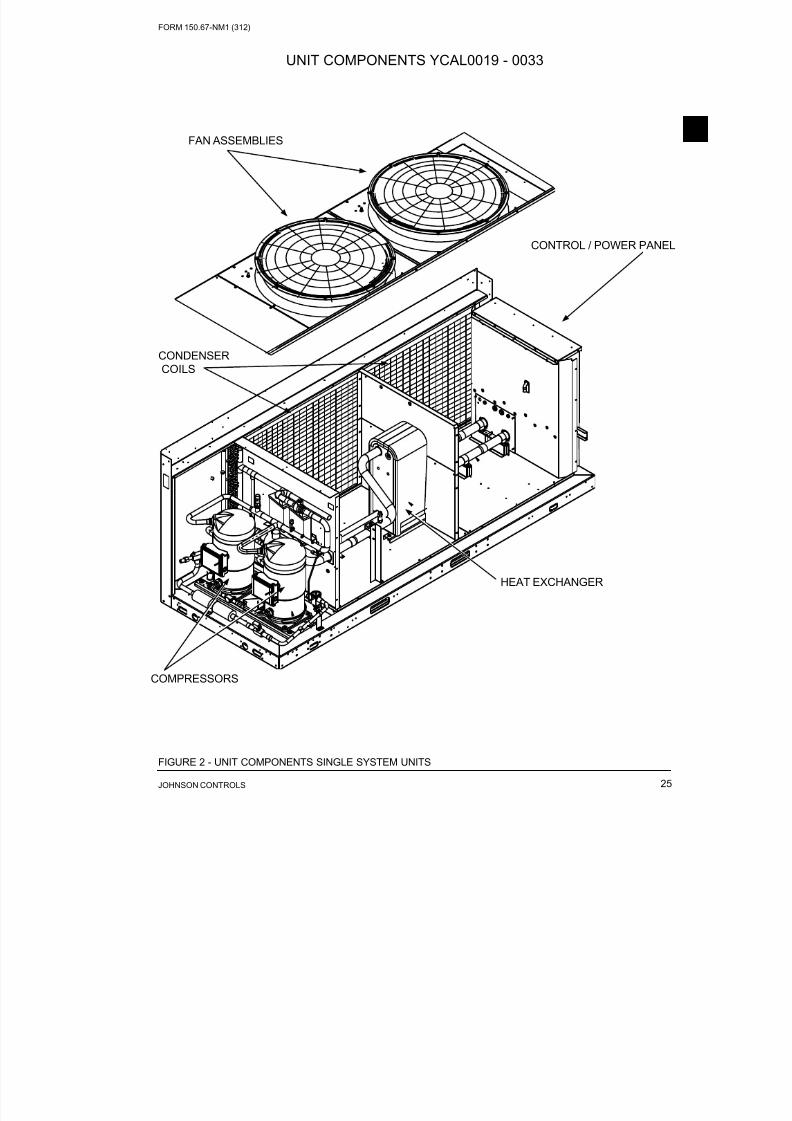
8/19/2019 Manual York
http://slidepdf.com/reader/full/manual-york 25/230
FORM 150.67-NM1 (312)
25JOHNSON CONTROLS
COMPRESSORS
FAN ASSEMBLIES
CONDENSER
COILS
CONTROL / POWER PANE
HEAT EXCHANGER
FIGURE 2 - UNIT COMPONENTS SINGLE SYSTEM UNITS
UNIT COMPONENTS YCAL0019 - 0033
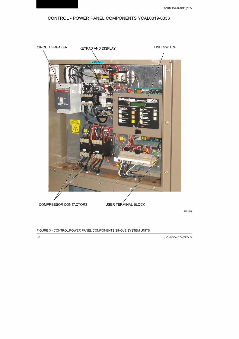
8/19/2019 Manual York
http://slidepdf.com/reader/full/manual-york 26/230JOHNSON CONTROLS26
FORM 150.67-NM1 (312)
Product Description
LD11463
KEYPAD AND DISPLAY UNIT SWITCH
COMPRESSOR CONTACTORS USER TERMINAL BLOCK
CIRCUIT BREAKER
FIGURE 3 - CONTROL/POWER PANEL COMPONENTS SINGLE SYSTEM UNITS
CONTROL - POWER PANEL COMPONENTS YCAL0019-0033

8/19/2019 Manual York
http://slidepdf.com/reader/full/manual-york 27/230
FORM 150.67-NM1 (312)
27JOHNSON CONTROLS
HEAT EXCHANGER
CONDENSER COILS
LD1247
COMPRESSORSCONTROL /
POWER PANE
FAN ASSEMBLIES
FIGURE 4 - UNIT COMPONENTS DUAL SYSTEM UNITS
UNIT COMPONENTS - YCAL0043 – 0066

8/19/2019 Manual York
http://slidepdf.com/reader/full/manual-york 28/230JOHNSON CONTROLS28
FORM 150.67-NM1 (312)
Product Description
LD11458a
FIGURE 5 - CONTROL/POWER PANEL COMPONENTS DUAL SYSTEM UNITS
TERMINAL BLOCK FAN FUSES CR1 / CR2
COMPRESSOR CONTACTS TB1 CTB1
CONTROL / POWER PANEL COMPONENTS - YCAL0043 – 0066

8/19/2019 Manual York
http://slidepdf.com/reader/full/manual-york 29/230
FORM 150.67-NM1 (312)
29JOHNSON CONTROLS
PRODUCT IDENTIFICATION NUMBER (PIN)
FEATURE DESCRIPTION OPTION DESCRIPTION
MODEL Model (PIN 1-4) YCAL YCAL
CAP Capacity (PIN 5-8)W
0019 0019
0022 0022
0028 0028
0033 0033
0043 0043
0046 0046
0052 0052
0056 0056
0066 0066
UNIT Unit Designator (PIN 9) E High Efciency
REF Refrigerant (PIN 10) C R-410a
VOLTS Voltage (PIN 11 & 12)
17 200/3/6028 230/3/60
40 380/3/60
46 460/3/60
58 575/3/60
STARTER Starter (PIN 13) X Across The Line Starter
DESIGN Design Series (PIN 14) E Design Series E
DEV Development Level (PIN 15) A Development Level A
POWER Power Field (PIN 16 & 17)
SX Single-Point Terminal Block
SD Single-Point Non-Fused Disconnect
BX Single-Point Circuit Breaker
QQ Special Power Option Required
TRANS Cntrl Transformer (PIN 18)
X No Control Transformer Required
T Control Transformer Required
Q Special Control Transformer Required
PFC Power Factor Capacitor (PIN 19)
X No Power Capacitor Required
C Power Capacitor Required
Q Special Power Capacitor Required
YCAL0043EE 46XEABASIC UNIT NOMENCLATURE
: High Efciency : Design Series E: Engineering
Change
or PIN Level
: YORK
: Chiller
: Air-Cooled
: Condensing
Unit
: Scroll
Even Number:
60 HZ Nominal TonsOdd Number:
50 HZ Nominal kW
1 2 3 4 5 6 7 8 9 10 11 12 13 14 15BASE PRODUCT TYPE NOMINAL CAPACITY UNIT DESIGNATOR REFRIGERANT VOLTAGE/STARTER DESIGN/DEVELOPMENT LEVE
Y 0 # # # E E 1 7 E C 1 # # # 2 8 A
A 4 0
4 6
5 8
L
X
: R-410A : 200 / 3/ 60
: 230 / 3 / 60
: 380 / 3 / 60
: 460 / 3 / 60
: 575 / 3 / 60
: Across the Line

8/19/2019 Manual York
http://slidepdf.com/reader/full/manual-york 30/230JOHNSON CONTROLS30
FORM 150.67-NM1 (312)
Product Description
FEATURE DESCRIPTION OPTION DESCRIPTION
AMB Ambient Kits (PIN 20)
X No Ambient Kits Required
L Low Ambient Kits Required
H High Ambient Kits Required
A High/Low Ambient Kits Required
Q Special Ambient Kits Required
BAS BAS Reset/Offset (PIN 21)
X No BAS Reset/Offset Required
M ISN Microgateway Required
T BAS Reset/Offset Required
Q Special BAS Reset/Offset Required
LCD Language (PIN 22)
X English
S Spanish
F French
G German
Q Special Language Required
RDOUT Readout Kits (PIN 23)
X No Readout Kit Required
R Discharge Readout Kit Required
Q Special Pressure Readout Required
SAFETY Safety Codes (PIN 24) L N American Safety Code (Cul/Cet)
SENSOR (PIN 25)X No Option Required
Q Special Quote
PUMP (PIN 26)
X No Motor Current
C Motor Current Readout
Q Special Quote
REMOTE Remote Panel (PIN 27)
X No Remote Panel Required
O OptiView Remote Panel Required
Q Special Remote Panel Required
SEQ Sequence Kit (PIN 28)
X No Sequence Kit Required
S Sequence Kit Required= {SEQ/S}
Q Special Sequence Required
TEMPLeaving Water Temp
(PIN 29, 30)
NUMLeaving Water Temp=
{TEMP/NUM} Degrees
QQ Special LWT Requirements
CHICAGO Chicago Code Kit (PIN 31)
X No Chicago Code Kit Required
C Chicago Code Kit Required
S Service Isolation Valves
B Both Chicago Code & Serv Isolation
Q Special Chicago Code Kit Required
VALVES Valves (PIN 32)X Standard Valves Required
Q Special Optional Valves Required
HGBP Hot Gas Bypass (PIN 33)
X No Hot Gas Bypass Required
1 Hot Gas Bypass Required-1 Circuit
2 Hot Gas Bypass Required-2 Circuit
Q Special Hot Gas Required
GAUGE (PIN 34)X No Option Required
Q Special Quote
PRODUCT IDENTIFICATION NUMBER (PIN) (CONT’D)

8/19/2019 Manual York
http://slidepdf.com/reader/full/manual-york 31/230
FORM 150.67-NM1 (312)
31JOHNSON CONTROLS
FEATURE DESCRIPTION OPTION DESCRIPTION
OVERLOAD (PIN 35)X No Option Required
Q Special Quote
PIN 36 (PIN 36)X No Option Required
Q Special Quote
HTR Crankcase Heater (PIN 37)X Crankcase Heater Standard
Q Special Crankcase Heater Required
DWP DWP (PIN 38)
X 150 PSIG DWP Waterside
3 300 PSIG DWP Waterside
Q Special DWP
INS Insulation (PIN 39)
X Standard Insulation
D Double Thick Insulation
Q Special Insulation Required
FLANGES Flanges (PIN 40)
X Standard Victaulic
V Victaulic to Flange Adapter
Q Special Flanges Required
FLOW Flow Switch (PIN 41)
X No Flow Switch Required
S One Flow Switch Required
T Two Flow Switches Required
U Three Flow Switches Required
DOne Differential Pressure Switch
Required
ETwo Differential Pressure Switches Re-
quired
FThree Differential Pressure Switches Re-
quired
Q Special Flow Switch Required
VESSEL Vessel Codes (PIN 42)
X UL Pressure Code Vessel
A ASME Pressure Vessel Code
Q Special Pressure Vessel Code
CLR Cooler (PIN 43)
X Standard Cooler Required
R Remote Cooler Required
Q Special Cooler Required
PIN 44 (PIN 44)X No Option Required
Q Special Quote
COILS Coils (PIN 45)
X Aluminum Coil
B Pre-Coated Fin Coil
C Copper Coil
P Post-Coated Dipped CoilQ Special Coil
PIN 46 (PIN 46)X No Option Required
Q Special Quote
FANMOTORS Fan Mot ors (PIN 47)X TEAO Fan Motors
Q Special Fan Motors Required
ENCL Enclosure Panel (PIN 48)
1 Wire Enclosures-Factory
7 Louvered Enclosure-Factory
Q Special Enclosures Panels
PRODUCT IDENTIFICATION NUMBER (PIN) (CONT’D)

8/19/2019 Manual York
http://slidepdf.com/reader/full/manual-york 32/230JOHNSON CONTROLS32
FORM 150.67-NM1 (312)
Product Description
FEATURE DESCRIPTION OPTION DESCRIPTION
ACOUSTIC Acoust ic Blanket (PIN 49)
X No Acoustic Blanket Required
B Acoustic Blanket Required
Q Special Acoustic Blanket Required
PIN 50 (PIN 50)X No Option Required
Q Special Quote
PIN 51 (PIN 51)X No Option Required
Q Special Quote
FANS Sound Fans (PIN 52)
X Standard Low Sound Fans Required
L Ultra Low Sound Fans Required
Q Special Sound Fans Required
PAINT (PIN 53)X No Option Required
Q Special Quote
ISOL Vibration Isolators (PIN 54)
X No Isolators Required
1 1” Deection Isolators Required
N Neoprene Isolators Required
S Seismic Isolators Required
Q Special Isolators Required
WARRANTY Warranty (PIN 55)
X 18 months parts only (year 1)
B 18 months labor (year 1) (entire unit)
C 30 months parts (year 1&2) (entire unit)
D 30 months P&L (year 1&2) (entire unit)
E48 months Compressor Parts Only (year
1-5)
F18 months (year 1) – (entire unit), 48
months P&L (year 2-5) (compressor only)
G 48 months parts (year 2-5) (entire unit)
H18 months labor (year 1) – (entire unit), 48
months (P&L) (year 2-5) (entire unit)
I18 months labor (year 1) – (entire unit), 30
months parts (year 1&2) (entire unit)
J18 months labor (year 1) – (entire unit), 48
months parts (year 2-5) (compressor only)
K18 months labor (year 1) – (entire unit), 48
months parts (year 2-5) (entire unit)
L
18 months labor (year 1) – (entire unit), 30
months parts (year 1&2) (entire unit) 48
month parts (year2-5) (compressor only)
M
18 months labor (year 1) – (entire unit), 48
months parts (year 1&2) (entire unit) 48month P&L (year2-5) (compressor only)
N
30 months parts (year 1&2) – (entire unit),
48 months parts (year 2-5) (compressor
only)
O30 months P&L (year 1&2) – (entire unit), 48
months parts (year 2-5) (compressor only)
P30 months P&L (year 1&2) – (entire unit), 48
months P&L (year 2-5) (compressor only)
R30 months P&L (year 1&2) – (entire unit), 48
months parts (year 2-5) (entire unit)
PRODUCT IDENTIFICATION NUMBER (PIN) (CONT’D)

8/19/2019 Manual York
http://slidepdf.com/reader/full/manual-york 33/230
FORM 150.67-NM1 (312)
33JOHNSON CONTROLS
FEATURE DESCRIPTION OPTION DESCRIPTION
Q Special Warranty
REFWTY Refrigerant Warranty (PIN 56)
X No Refrigerant Warranty Required
1 1 Year Refrigerant
2 2 Year Refrigerant
5 5 Year Refrigerant
SHIP Ship Instructions (PIN 57)
X No Option Required
A Buy American Act Compliance
B
Both Buy American Act Compliance and
Container Shipping Kit
C Container Shipping Kit (Factory Load)
P Container Shipping Kit (Factory Prep)
Q Special Quote
PIN 58 (PIN 58)
X No Option Required
Q Special Quote
PIN 59 (PIN 59)
X No Option Required
Q Special Quote
PIN 60 (PIN 60)
X No Option Required
Q Special Quote
MFG Plant of Mfg. (PIN 61) R Plant of Manufacture-Monterrey
LOC Mfg. Location
MEX Mexico
SAT San Antonio
YW YorkWorks VersionCV YorkWorks ConVersion
UV YorkWorks Version
SQ Special Quote Q Special Quote
PRODUCT IDENTIFICATION NUMBER (PIN) (CONT’D)

8/19/2019 Manual York
http://slidepdf.com/reader/full/manual-york 34/230JOHNSON CONTROLS34
FORM 150.67-NM1 (312)
Product Description
FIGURE 6 - REFRIGERANT FLOW DIAGRAM
LD11417
OPTIONAL
AIR COOLED CONDENSERS
OPTIONALDISCHARGE LINEBALL VALVE
HOT DISCHARGEGAS LINE
OPTIONALSERVICE VALVE
REFRIGERANT FLOW DIAGRAM

8/19/2019 Manual York
http://slidepdf.com/reader/full/manual-york 35/230
FORM 150.67-NM1 (312)
35JOHNSON CONTROLS
SECTION 3 – HANDLING AND STORAGE
DELIVERY AND STORAGE
To ensure consistent quality and maximum reliability,
all units are tested and inspected before leaving the fac-
tory. Units are shipped completely assembled and con-
taining refrigerant under pressure. Units are shipped
without export crating unless crating has been speci-fied on the Sales Order.
If the unit is to be put into storage, prior to installation,
the following precautions should be observed:
• The chiller must be “blocked” so that the base is
not permitted to sag or bow.
• Ensure that all openings, such as water connec-
tions, are securely capped.
• Do not store where exposed to ambient air tem-
peratures exceeding 110 °F (43 °C).
• The condensers should be covered to protect the
ns from potential damage and corrosion, particu-
larly where building work is in progress.
• The unit should be stored in a location where there
is minimal activity in order to limit the risk of ac-
cidental physical damage.
• To prevent inadvertent operation of the pressure
relief devices the unit must not be steam cleaned.
• It is recommended that the unit is periodically in-
spected during storage.
INSPECTION
Remove any transit packing and inspect the unit to en-
sure that all components have been delivered and that
no damage has occurred during transit. If any damage
is evident, it should be noted on the carrier’s freight bill
and a claim entered in accordance with the instructions
given on the advice note.
Major damage must be reported immediately to your
local Johnson Controls representative.
MOVING THE CHILLER (YCAL0043 – 0066
DUAL SYSTEM ONLY)
Prior to moving the unit, ensure that the installation
site is suitable for installing the unit and is easily ca-
pable of supporting the weight of the unit and all as-
sociated services.
The units are designed to be lifted using cables. A
spreader bar or frame should be used in order to pre-
vent damage to the unit from the lifting chains.
Units are provided with lifting eyes in the sides of the
base frame, which can be attached to directly using
shackles or safety hooks.
The unit must only be lifted by the base
frame at the points provided. Nevermove the unit on rollers, or lift the
unit using a forklift truck.
Care should be taken to avoid damaging the condenser
cooling fins when moving the unit.
Lifting Weights
For details of weights and weight distribution, refer to
the data shipped in the chiller information packet and
unit nameplate.
The unit should be lifted by inserting
hooks through the holes provided in
unit base rails. Spreader bars should
be used to avoid crushing the unit
frame rails with the lifting chains (see
Figure 8).
MOVING THE CHILLER (YCAL0019 – 0033
SINGLE CIRCUIT ONLY)
Prior to moving the unit, ensure that the installation
site is suitable for installing the unit and is easily ca-
pable of supporting the weight of the unit and all as
sociated services.
The units are designed to be lifted using cables or an
appropriate forklift. Refer to the unit data plate for unit
weight. When using lifting cables, a spreader bar or
frame should be used in order to prevent damage to the
unit from the lifting chains.
Units are provided with lifting eyes in the sides of the
base frame, which can be attached to directly usingshackles or safety hooks.
The unit must only be lifted by the base
frame at the points provided.
Care should be taken to avoid damaging the condenser
cooling fins when moving the unit.

8/19/2019 Manual York
http://slidepdf.com/reader/full/manual-york 36/230JOHNSON CONTROLS36
FORM 150.67-NM1 (312)
Handling and Storage
UNIT RIGGING
Lifting Instructions are placed on a label on the chiller
and on the shipping bag.
Forks must extend beyond the width of the unit for proper
lift. The thickness of the fork blade must be smaller then
the opening of the lifting hole. Improper fork positioning
could result in damage to the unit.
FIGURE 7 - UNIT RIGGING/LIFTING (YCAL0019 – 0033 SINGLE CIRCUIT MODELS ONLY)
Lifting Weights
For details of weights and weight distribution, refer to
the data shipped in the chiller information packet and
unit nameplate.
48.00 in.

8/19/2019 Manual York
http://slidepdf.com/reader/full/manual-york 37/230
FORM 150.67-NM1 (312)
37JOHNSON CONTROLS
Use spreader bars to avoid lifting chains hitting the
chiller.
Never lift the chiller using a forklift or
by hooking to the top rails. Use only
the lifting holes provided.
Lifting Instructions are placed on a label on the chiller
and on the shipping bag.
LD10951
FIGURE 8 - UNIT RIGGING/LIFTING (YCAL0043- 0066 DUAL CIRCUIT MODELS)

8/19/2019 Manual York
http://slidepdf.com/reader/full/manual-york 38/230JOHNSON CONTROLS38
FORM 150.67-NM1 (312)
THIS PAGE INTENTIONALLY LEFT BLANK

8/19/2019 Manual York
http://slidepdf.com/reader/full/manual-york 39/230
FORM 150.67-NM1 (312)
39JOHNSON CONTROLS
To ensure warranty coverage, this
equipment must be commissioned
and serviced by an authorized John-
son Controls service mechanic or a
qualied service person experienced
in chiller installation. Installationmust comply with all applicable codes,
particularly in regard to electrical
wiring and other safety elements such
as relief valves, HP cutout settings,
design working pressures, and ven-
tilation requirements consistent with
the amount and type of refrigerant
charge.
Lethal voltages exist within the control panels. Before servicing, open and tag
all disconnect switches.
INSTALLATION CHECKLIST
The following items, 1 through 5, must be checked be-
fore placing the units in operation.
1. Inspect the unit for shipping damage.
2. Rig unit using spreader bars.
3. Open the unit only to install water piping sys-
tem. Do not remove protective covers from water
connections until piping is ready for attachment.
Check water piping to ensure cleanliness.
4. Pipe unit using good piping practice (see ASHRAE
handbook section 215 and 195).
5. Check to see that the unit is installed and operated
within limitations (Refer to LIMITATIONS).
The following pages outline detailed procedures to be
followed to install and start-up the chiller.
HANDLING
These units are shipped as completely assembled units
containing full operating charge, and care should be
taken to avoid damage due to rough handling.
SECTION 4 – INSTALLATION
INSPECTION
Immediately upon receiving the unit, it should be in-
spected for possible damage which may have occurred
during transit. If damage is evident, it should be noted
in the carrier’s freight bill. A written request for inspec-
tion by the carrier’s agent should be made at once. See“Instruction” manual, Form 50.15-NM for more infor-
mation and details.
LOCATION AND CLEARANCES
These units are designed for outdoor installations on
ground level, rooftop, or beside a building. Location
should be selected for minimum sun exposure and to
insure adequate supply of fresh air for the condenser
The units must be installed with sufficient clearances
for air entrance to the condenser coil, for air discharge
away from the condenser, and for servicing access.
In installations where winter operation is intended and
snow accumulations are expected, additional height
must be provided to ensure normal condenser air flow
Clearances are listed on Figure 30.
Foundation
The unit should be mounted on a flat and level foun-
dation, floor, or rooftop capable of supporting the en-
tire operating weight of the equipment. See “Physical
Data” for operating weight. If the unit is elevated be-yond the normal reach of service personnel, a suitable
catwalk must be capable of supporting service person-
nel, their equipment, and the compressors.
Ground Level Locations
It is important that the units be installed on a sub-
stantial base that will not settle. A one piece concrete
slab with footers extended below the frost line is
highly recommended. Additionally, the slab should
not be tied to the main building foundations as noise
and vibration may be transmitted. Mounting holes are
provided in the steel channel for bolting the unit to its
foundation (see Section 5 “Dimensions”).
For ground level installations, precautions should be
taken to protect the unit from tampering by or injury to
unauthorized persons. Screws and/or latches on access
panels will prevent casual tampering. However, furthe
safety precautions such as a fenced-in enclosure or
locking devices on the panels may be advisable.

8/19/2019 Manual York
http://slidepdf.com/reader/full/manual-york 40/230JOHNSON CONTROLS40
FORM 150.67-NM1 (312)
Installation
Rooftop Locations
Choose a spot with adequate structural strength to
safely support the entire weight of the unit and service
personnel. Care must be taken not to damage the roof.
Consult the building contractor or architect if the roof is
bonded. Roof installations should have wooden beams
(treated to reduce deterioration), cork, rubber, or vibra-tion isolators under the base to minimize vibration.
Noise Sensitive Locations
Efforts should be made to assure that the chiller is not
located next to occupied spaces or noise sensitive areas
where chiller noise level would be a problem. Chiller
noise is a result of compressor and fan operation. Con-
siderations should be made utilizing noise levels pub-
lished in the YORK Engineering Guide for the specific
chiller model. Sound blankets for the compressors and
low sound fans are available.
SPRING ISOLATORS (OPTIONAL)
When ordered, four (4) isolators will be furnished.
Identify the isolator, locate at the proper mounting point, and adjust per instructions.
COMPRESSOR MOUNTING
The compressors are mounted on four (4) rubber iso-lators. The mounting bolts should not be loosened oradjusted at installation of the chiller.
REMOTE COOLER OPTION
Not available at this time.
CHILLED LIQUID PIPING
When the unit(s) has been located in its final position,the unit water piping may be connected. Normal instal-lation precautions should be observed in order to re-ceive maximum operating efficiencies. Piping should be kept free of all foreign matter. All chilled waterevaporator piping must comply in all respects with lo-cal plumbing codes and ordinances.
Since elbows, tees and valves decrease pump capacity,all piping should be kept as straight and as simple as possible. All piping must be supported independentof the chiller.
Consideration should be given to com-
pressor access when laying out water
piping. Routing the water piping too
close to the unit could make compres-
sor servicing/replacement difcult.
Hand stop valves should be installed in all lines to fa-
cilitate servicing.
Piping to the inlet and outlet connections of the chillershould include high-pressure rubber hose or pipingloops to ensure against transmission of water pump vi- bration. The necessary components must be obtained
in the field.
Drain connections should be provided at all low pointsto permit complete drainage of the cooler and systemwater piping.
A small valve or valves should be installed at the high-est point or points in the chilled water piping to allowany trapped air to be purged. Vent and drain connec-tions should be extended beyond the insulation to makethem accessible.
The piping to and from the cooler must be designed tosuit the individual installation. It is important that thefollowing considerations be observed:
1. The chilled liquid piping system should be laidout so that the circulating pump discharges di-rectly into the cooler. The suction for this pumpshould be taken from the piping system returnline and not the cooler. This piping scheme isrecommended, but is not mandatory.
2. The inlet and outlet cooler connection sizes are 3"(YCAL0043 to YCAL0066).
3. A strainer, preferably 40 mesh, must be installedin the cooler inlet line just ahead of the cooler.This is important to protect the cooler from en-trance of large particles which could cause dam-age to the evaporator.
4. All chilled liquid piping should be thoroughlyushed to free it from foreign material beforethe system is placed into operation. Use care notto ush any foreign material into or through thecooler.
5. As an aid to servicing, thermometers and pressuregauges should be installed in the inlet and outletwater lines.
6. The chilled water lines that are exposed to outdoorambients should be wrapped with supplemen-tal heater cable and insulated to protect againstfreeze-up during low ambient periods, and to pre-vent formation of condensation on lines in warmhumid locations.
7. A chilled water ow switch, (either by YORK orothers) must be installed in the leaving water pip-ing of the cooler. There should be a straight hori-zontal run of at least 5 diameters on each side ofthe switch. Adjust the ow switch paddle to the

8/19/2019 Manual York
http://slidepdf.com/reader/full/manual-york 41/230
FORM 150.67-NM1 (312)
41JOHNSON CONTROLS
size of the pipe in which it is to be installed (seemanufacturer’s instructions furnished with theswitch). The switch is to be wired to terminals 13and 14 of CTB1 located in the control panel, asshown on the unit wiring diagram.
The ow switch MUST NOT be used
to start and stop the chiller (i.e. start -
ing and stopping the chilled water pump). It is intended only as a safety
switch.
PIPEWORK ARRANGEMENT
The following are suggested pipework arrangementsfor single unit installations, for multiple unit installa-
tions, each unit should be piped as shown.
Recommendations of the Building ServicesResearch Association.
DUCT WORK CONNECTION
General Requirements
The following duct work recommendations are intend-
ed to ensure satisfactory operation of the unit. Failure
to follow these recommendations could cause damage
to the unit, or loss of performance, and may invalidate
the warranty.
When ducting is to be fitted to the fan discharge it is
recommended that the duct should be the same cross-
sectional area as the fan outlet and straight for at least
three feet (1 meter) to obtain static regain from the fan
Duct work should be suspended with flexible hang-
ers to prevent noise and vibration being transmitted to
the structure. A flexible joint is also recommended be
tween the duct attached to the fan and the next section
for the same reason. Flexible connectors should not be
allowed to concertina.
The unit(s) is not designed to take structural loading
No significant amount of weight should be allowed to
rest on the fan outlet flange, deck assemblies or con-
denser coil module. No more than 3 feet (1 meter) of
light construction duct work should be supported by
the unit. Where cross winds may occur, any duct work
must be supported to prevent side loading on the unit.
If the ducts from two or more fans are to be combined
into a common duct, back-flow dampers should be fit-
ted in the individual fan ducts. This will prevent re-
circulation of air when only one of the fans is running
Units are supplied with outlet guards for safety and to
prevent damage to the fan blades. If these guards are
removed to fit duct work, adequate alternative precau
tions must be taken to ensure persons cannot be harmed
or put at risk from rotating fan blades.
WIRING
Liquid Chillers are shipped with all factory-mounted
controls wired for operation.
Field Wiring
Power wiring must be provided through a fused discon-
nect switch to the unit terminals (or optional molded dis-
connect switch) in accordance with N.E.C. or local code
requirements. Minimum circuit ampacity and maximum
dual element fuse size are given in Table 7.
Copper power wiring only should be used for supply-ing power to the chiller. This is recommended to avoidsafety and reliability issues resulting from connectionfailure at the power connections to the chiller. Aluminum wiring is not recommended due to thermal char-acteristics that may cause loose terminations result-ing from the contraction and expansion of the wiringAluminum oxide may also build up at the terminationcausing hot spots and eventual failure. If aluminumwiring is used to supply power to the chiller, AL-CUcompression fittings should be used to transition fromFIGURE 9 - CHILLED LIQUID SYSTEM
LD06597A
ISOLATING VALVE - NORMALLY OPE
ISOLATING VALVE - NORMALLY CLO
FLOW REGULATING VALVE
FLOW MEASUREMENT DEVICE
STRAINER
PRESSURE TAPPING
FLOW SWITCH
LD06596

8/19/2019 Manual York
http://slidepdf.com/reader/full/manual-york 42/230JOHNSON CONTROLS42
FORM 150.67-NM1 (312)
Installation
aluminum to copper. This transition should be done inan external box separate to the power panel. Copperconductors can then be run from the box to the chiller.
A 120-1-60, 15 amp source must be supplied for the
control panel through a fused disconnect when a con-
trol panel transformer (optional) is not provided (Refer
to Figure 10).
See unit wiring diagrams for field and power wiringconnections, chilled water pump starter contacts, alarmcontacts, compressor run status contacts, PWM input,and load limit input. Refer to Section 8 “Unit Opera-tion” for a detailed description of operation concerningaforementioned contacts and inputs.
Evaporator Pump Start Contacts
Terminal block TB1 terminals 23 to 24, are normally-open contacts that can be used to switch field supplied power to provide a start signal to the evaporator pump
contactor. The contacts will be closed when any of thefollowing conditions occur:
1. Low Leaving Chilled Liquid Fault
2. Any compressor is running
3. Daily schedule is not programmed OFF and the
Unit Switch is ON
The pump will not run if the micro panel has been pow-ered up for less than 30 seconds, or if the pump has runin the last 30 seconds, to prevent pump motor over-
heating. Refer to Figure 11 and unit wiring diagram.
System Run Contacts
Contacts are available to monitor system status. Nor-mally-open auxiliary contacts from each com pressorcontactor are wired in parallel with TB1 terminals 25to 26 for system 1, and TB1 terminals 27 to 28 for sys-tem 2 (YCAL0043 to YCAL0066). Refer to Figure 5,11 and unit wiring diagram.
Alarm Status Contacts
Normally-open contacts are available for each re-frigerant system. These normally-open contacts close
when the system is functioning normally. The respec-tive contacts will open when the unit is shut down on aunit fault, or locked out on a system fault. Field connec-tions are at TB1 terminals 29 to 30 (system 1), and ter-minals 31 to 32 (system 2 YCAL0043 to YCAL0066).
Remote Start/Stop Contacts
To remotely start and stop the chiller, dry contactscan be wired in series with the flow switch and CTB1terminals 13 to 14. Refer to Figure 5, 11 and unit wir-ing diagram.
Remote Emergency Cutoff
Immediate shutdown of the chiller can be accomplished
by opening a field-installed dry contact to break the
electrical circuit between terminals 5 to L on terminal
block TB1. The unit is shipped with a factory jumper
installed between terminals 5 to L, which must be re-
moved if emergency shutdown contacts are installed.
Refer to Figure 11 and unit wiring diagram.
Remote Temp Reset Input
The Remote Temp Reset input allows reset of the
chilled liquid set point by supplying a voltage or cur-
rent signal field wiring should be connected to CTB1
terminals A+ to A-. A detailed explanation is provided
in the Unit Control section. Refer to Figure’s. 3 and 5
and unit wiring diagram.
Load Limit Input
Load limiting is a feature that prevents the unit fromloading beyond a desired value. The unit can be “load
limited” either 33%, 40%, 50%, 66% or 80%, depend-
ing on the number of compressors on unit. The field
connections are wired to CTB1 terminals 13 to 21, and
work in conjunction with the PWM inputs. A detailed
explanation is provided in the Unit Control section.
Refer to Figure 5, 11 and unit wiring diagram.
When using the Load Limit feature,
the PWM feature will not function
– SIMULTANEOUS OPERATION
OF LOAD LIMITING AND TEM-
PERATURE RESET (PWM INPUT)
CANNOT BE DONE.
Flow Switch Input
The flow switch is field wired to CTB1 terminals 13
and 14. See Figure 4 and the unit wiring diagram.
COMPRESSOR HEATERS
Compressor heaters are standard. Non-standard appli-
cations are as follows:
• ZP103, ZP120 and ZP137 compressors utilize
90W heaters
• ZP180 compressors utilize 70W heaters
• ZP235 compressors utilize 120W heaters
If power is OFF more than two hours, the crankcase
heaters must be energized for between 18 and 24 hours

8/19/2019 Manual York
http://slidepdf.com/reader/full/manual-york 43/230
FORM 150.67-NM1 (312)
43JOHNSON CONTROLS
prior to restarting a compressor. This will assure that
liquid slugging and oil dilution does not damage the
compressors on start.
RELIEF VALVES
Relief valves are located on both the high and low pres-
sure side of the piping. High side relief valve pressure
setting is 650 PSIG. Low side relief valve pressuresetting is 450 PSIG.
HIGH PRESSURE CUTOUT
A high pressure cutout is installed in the discharge pip-
ing of each system. The cutout opens at 585 PSIG plus
or minus 10 PSIG and closes at 440 PSIG plus or mi-
nus 25 PSIG.

8/19/2019 Manual York
http://slidepdf.com/reader/full/manual-york 44/230JOHNSON CONTROLS44
FORM 150.67-NM1 (312)
Installation
FIGURE 10 - SINGLE-POINT SUPPLY CONNECTION – TERMINAL BLOCK, NON-FUSED DISCONNECT
SWITCH OR CIRCUIT BREAKER (0043 – 0066)
SINGLE-POINT SUPPLY CONNECTION – TERMINAL BLOCK, NON-FUSED
DISCONNECT SWITCH OR CIRCUIT BREAKER
It is possible that multiple sources of
power can be supplying the unit power
panel. To prevent serious injury or
death, the technician should verify
that NO LETHAL VOLTAGES are
present inside the panel AFTER dis-
connecting power, PRIOR to working
on equipment.
The unit evaporator heater uses
120VAC. Disconnecting 120VAC pow-
er from the unit, at or below freezing
temperatures, can result in damage to
the evaporator and unit as a result of
the chilled liquid freezing.
Electrical Notes and Legend located on Page 59.
LD07719
Power Panel Control Panel
Terminal Block,
NF Disconnect SW
or Circuit Breaker
1L1 1L2 1L3
G R D
MICROPANEL
2
L
CTB2
13 14
CTB1
Field Provided Unit Power Supply
Field Provided 120-1-60Micropanel Power Supply if ControlTransformer not Supplied
Flow Switch
See electrical note 9
Power Panel Control PanelPower Panel Control Panel
Terminal Block,NF Disconnect SWor Circuit Breaker
1L1 1L2 1L31L1 1L2 1L3
G R D
G R D
G R D
MICROPANEL
2
L
CTB2
2
L
CTB2
13 1413 14
CTB1
Field Provided Unit Power Supply
Field Provided 120-1-60Micropanel Power Supply if ControlTransformer not Supplied
Flow Switch
See electrical note 9
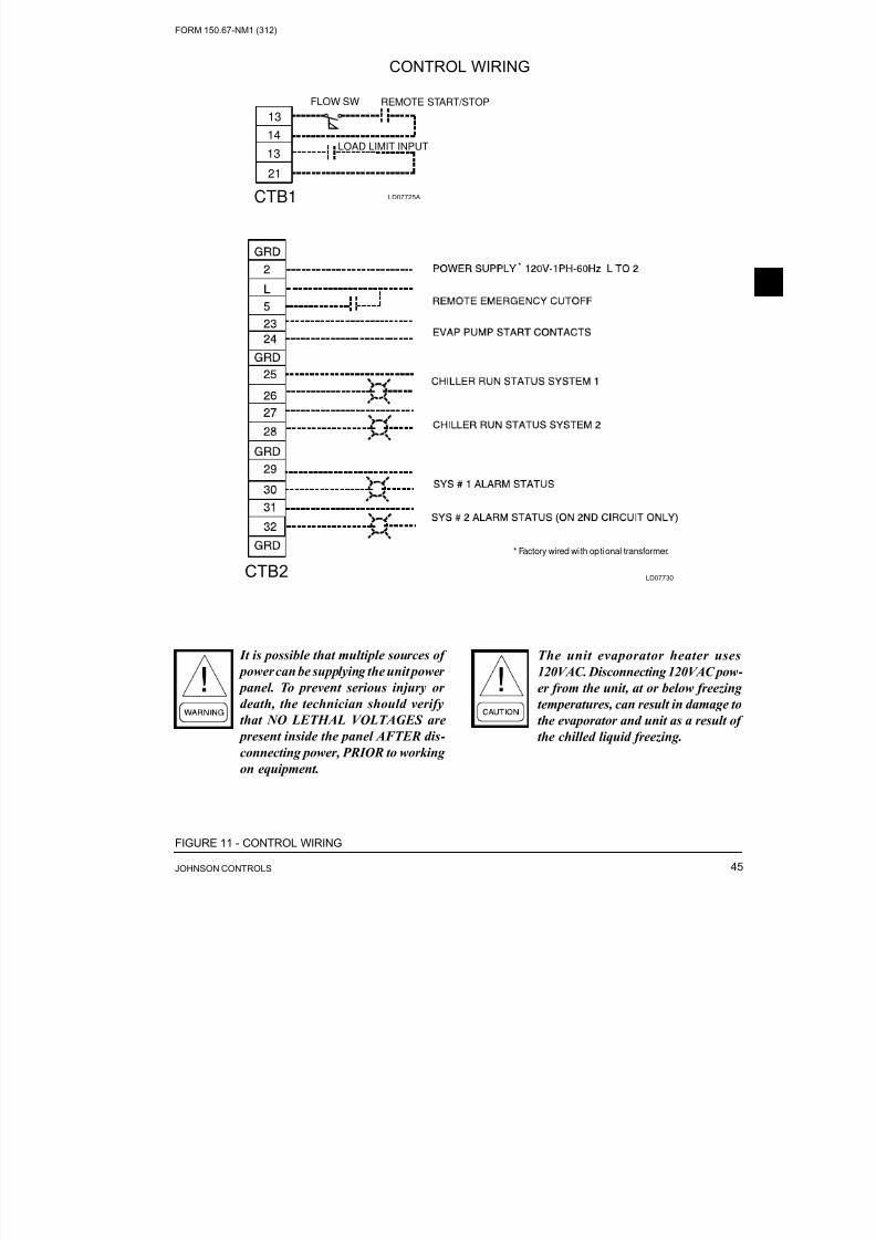
8/19/2019 Manual York
http://slidepdf.com/reader/full/manual-york 45/230
FORM 150.67-NM1 (312)
45JOHNSON CONTROLS
CTB1
21
13LOAD LIMIT INPUT
14
13
FLOW SW REMOTE START/STOP
FIGURE 11 - CONTROL WIRING
CONTROL WIRING
*
* Factory wired wi th optional transformer.
LD07730
LD07725A
It is possible that multiple sources of
power can be supplying the unit power
panel. To prevent serious injury ordeath, the technician should verify
that NO LETHAL VOLTAGES are
present inside the panel AFTER dis-
connecting power, PRIOR to working
on equipment.
The unit evaporator heater uses
120VAC. Disconnecting 120VAC pow-
er from the unit, at or below freezingtemperatures, can result in damage to
the evaporator and unit as a result of
the chilled liquid freezing.
CTB2

8/19/2019 Manual York
http://slidepdf.com/reader/full/manual-york 46/230JOHNSON CONTROLS46
FORM 150.67-NM1 (312)
THIS PAGE INTENTIONALLY LEFT BLANK

8/19/2019 Manual York
http://slidepdf.com/reader/full/manual-york 47/230
FORM 150.67-NM1 (312)
47JOHNSON CONTROLS
OPERATIONAL LIMITATIONS (ENGLISH)
Voltage Limitations
The following voltage limitations are absolute and
operation beyond these limitations may cause serious
damage to the compressor.
Excessive ow will cause damage to
the cooler. Do not exceed max. cooler
ow. Special care should be taken
when multiple chillers are fed by a
single pump.
NOTES:
1. For leaving brine temperature below 40 °F (4.4 °C), contact your nearest Johnson Controls Ofce for application requirements.
2. For leaving water temperature higher than 55 °F (12.8 °C), contact the nearest Johnson Controls Ofce for application guidelines.
3. The evaporator is protected against freezing to -20 °F (-28.8 °C) with an electric heater as standard.
4. For operation at temperatures below 25 °F (-3.9 °C), the optional Low Ambient Kit will need to be installed on the system(for YCAL0043 to YCAL0065).
5. For operation at temperatures above 115 °F (46.1 °C), the optional High Ambient Kit will need to be installed on the system.
TABLE 1 - TEMPERATURES AND FLOWS
ENGLISH
YCAL
LEAVING WATER
TEMPERATURE ( °F)
COOLER FLOW (GPM) AIR ON CONDENSER ( °F)
MINIMUM MAXIMUM MINIMUM MAXIMUM MINIMUM MAXIMUM
0019 40 55 17 68 0 125
0022 40 55 21 84 0 125
0028 40 55 30 150 0 125
0033 40 55 34 150 0 125
0043 40 55 40 200 0 125
0046 40 55 40 200 0 125
0052 40 55 40 300 0 125
0056 40 55 60 300 0 125
0066 40 55 60 300 0 125
TABLE 2 - VOLTAGE LIMITATIONS
UNIT POWER MINIMUM MAXIMUM
200-3-60 180 220
230-3-60 207 253
380-3-60 355 415
460-3-60 414 506
575-3-60 517 633
SECTION 5 – TECHNICAL DATA

8/19/2019 Manual York
http://slidepdf.com/reader/full/manual-york 48/230JOHNSON CONTROLS48
FORM 150.67-NM1 (312)
Technical Data
Note: Water Pressure Drop Curves may extend past the minimum and maximum water ow ranges.
YCAL0019-0033 HEAT EXCHANGER FLOW, GPM
LD14085
YCAL COOLER CURVE
0019 A
0022 B
0028 D
0033 C
ENGLISH
0.1
1.0
10.0
100.0
1000.0
1 10 100 1000
FLOW, GPM
P R E S S U R E
D R O P , F t H 2 O
A
C
B
D

8/19/2019 Manual York
http://slidepdf.com/reader/full/manual-york 49/230
FORM 150.67-NM1 (312)
49JOHNSON CONTROLS
ENGLISH
1
10
100
10 100 100
FLOW, GPM
P r e s s D r o p ,
F t H
2 O
A
B C
YCAL COOLER CURVE
0043 A
0046 B
0052 B
0056 C
0066 C
Note: Water Pressure Drop Curves may extend past the minimum and maximum water ow ranges.
LD1245
YCAL0043-0066 HEAT EXCHANGER FLOW, GPM

8/19/2019 Manual York
http://slidepdf.com/reader/full/manual-york 50/230JOHNSON CONTROLS50
FORM 150.67-NM1 (312)
Technical Data
OPERATIONAL LIMITATIONS (SI)
TABLE 3 - TEMPERATURES AND FLOWS (SI)
VOLTAGE
LIMITATIONS
YCAL
LEAVING WATER
TEMPERATURE ( °C)COOLER FLOW (L/S) AIR ON CONDENSER ( °C)
MINIMUM MAXIMUM MINIMUM MAXIMUM MINIMUM MAXIMUM
0019 4.4 12.8 1.1 4.3 -17.7 51.7
0022 4.4 12.8 1.3 5.3 -17.7 51.7
0028 4.4 12.8 1.3 9.5 -17.7 51.7
0033 4.4 12.8 2.2 9.5 -17.7 51.7
0043 4.4 12.8 2.5 12.6 -17.7 51.7
0046 4.4 12.8 2.5 12.6 -17.7 51.7
0052 4.4 12.8 3.8 18.9 -17.7 51.7
0056 4.4 12.8 3.8 18.9 -17.7 51.7
0066 4.4 12.8 3.8 18.9 -17.7 51.7
Voltage Limitations
The following voltage limitations are absolute and
operation beyond these limitations may cause serious
damage to the compressor.
Excessive ow will cause damage to
the cooler. Do not exceed max. cooler ow. Special care should be taken
when multiple chillers are fed by a
single pump.
NOTES:
1. For leaving brine temperature below 40 °F (4.4 °C), contact your nearest YORK Ofce for application requirements.
2. For leaving water temperature higher than 55 °F (12.8 °C), contact the nearest YORK Ofce for application guidelines.
3. The evaporator is protected against freezing to -20 °F (-28.8 °C) with an electric heater as standard.
4. For operation at temperatures below 25 °F (-3.9 °C), the optional Low Ambient Kit will need to be installed on the system.
5. For operation at temperatures above 110 °F (43 °C), the optional High Ambient Kit will need to be installed on the system.
TABLE 4 - VOLTAGE LIMITATIONS
UNIT POWER MINIMUM MAXIMUM
200-3-60 180 220
230-3-60 207 253
380-3-60 355 415
460-3-60 414 506
575-3-60 517 633
TABLE 5 - ETHYLENE AND PROPOLYNE GLYCOL CORRECTION FACTORS
ETHYLENE GLYCOL PROPYLENE GLYCOL
%
WEIGHTTONS
COMPR
KW
GPM F/
TON
PRESS
DROP
FREEZE
PT
%
WEIGHTTONS
COMPR
KW
GPM F/
TON
PRESS
DROP
FREEZE
PT
10.0 1.0 1.0 24.3 1.0 26.2 10.0 1.0 1.0 24.0 1.0 26.0
20.0 1.0 1.0 25.1 1.1 17.9 20.0 1.0 1.0 24.3 1.1 19.0
30.0 1.0 1.0 25.9 1.2 6.7 30.0 1.0 1.0 24.9 1.3 9.0
40.0 1.0 1.0 26.9 1.4 -8.1 40.0 1.0 1.0 25.6 1.4 -6.0
50.0 1.0 1.0 28.0 1.6 -28.9 50.0 0.9 1.0 26.6 1.7 -28.0

8/19/2019 Manual York
http://slidepdf.com/reader/full/manual-york 51/230
FORM 150.67-NM1 (312)
51JOHNSON CONTROLS
OPERATIONAL LIMITATIONS (SI)
Note: Water Pressure Drop Curves may extend past the minimum and maximum water ow ranges.
YCAL0019-0033 HEAT EXCHANGER FLOW, GPM
LD14086
YCAL COOLER CURVE
0019 A
0022 B
0028 D
0033 C
SI
0.1
1.0
10.0
100.0
1000.0
0.1 1 10 100
FLOW, L/S
P R E S S U R E
D R O
P , k P A
A
C
B
D

8/19/2019 Manual York
http://slidepdf.com/reader/full/manual-york 52/230JOHNSON CONTROLS52
FORM 150.67-NM1 (312)
Technical Data
SI
1
10
100
1000
1 10 100
FLOW, L/S
P r e
s s D r o p ,
k P A
B
AC
OPERATIONAL LIMITATIONS (SI)
Note: Water Pressure Drop Curves may extend past the minimum and maximum water ow ranges.
LD12452
YCAL0043-0066 HEAT EXCHANGER FLOW, GPM
YCAL COOLER CURVE
0043 A
0046 B
0052 B
0056 C
0066 C

8/19/2019 Manual York
http://slidepdf.com/reader/full/manual-york 53/230
FORM 150.67-NM1 (312)
53JOHNSON CONTROLS
PHYSICAL DATA (ENGLISH)
YCAL0019_ – YCAL0066_
TABLE 6 - PHYSICAL DATA (ENGLISH)
60Hz
Model No. YCAL 0019 0022 0028 0033 0043 0046 0052 0056 0066
Length 109.8 109.8 118.6 118.6 144.8 144.8 148.8 148.8 153.6
Width 44.7 44.7 44.7 44.7 90.6 90.6 90.6 90.6 90.6
Height 46.1 46.1 50 50 47.8 47.8 62.6 62.6 62.6
Nominal Tons 14.5 17.8 24.3 28 34.9 38 45.2 45.2 60.1
Number of Refrigerant Circuits 1 1 1 1 2 2 2 2 2
25 30 45 50 35/35 40/35 45/45 50/50 65/65
Oil Charge, gallons ckt1/ckt2 1.8 1.8 1.7 2.2 1.8/1.8 1.8/1.8 1.7/1.7 1.7/1.7 2.3/2.2
Shipping WeightAlum. Fin Coils, lbs 1454 1567 1799 2034 2942 2968 3196 3208 4097
Copper Fin Coils, lbs 1597 1781 2005 2240 3300 3326 3673 3685 4703
Operating WeightAlum. Fin Coils, lbs 1481 1597 1829 2077 2967 3001 3233 3245 4142
Copper Fin Coils, lbs 1624 1811 2035 2283 3325 3359 3710 3722 4748
Nominal Comp. Capacity
Comp. 1 8 10 15 15 10 12 13 15 20
Comp. 2 8 10 13 15 10 12 13 15 20
Comp. 3 – – – – – – – – –
Comp. 4 – – – – 10 10 13 15 15
Comp. 5 – – – – 10 10 13 15 15
Comp. 6 – – – – – – – – –
Condenser
34.7 34.7 43.5 43.5 87 87 116 116 128
2 3 3 3 2 2 3 3 3
X X X X 2 2 3 3 3
Fins per Inch 17 17 13 13 17 17 17 17 13
Condenser Fans, Low Sound
Number of Fans2 2 2 2 2 2 2 2 2
X X X X 2 2 2 2 2
Fan Power hp/fan 0.3 0.3 1.2 1.2 1.2 1.2 1.2 1.2 1.2
Fan RPM 920 920 950 950 950 950 950 950 950
Total Chiller CFM 10833 10833 20000 20000 39500 39500 43333 43333 43333
Condenser Fans, Ultra Quiet
Number of Fans2 2 2 2 2 2 2 2 2
X X X X 2 2 2 2 2
Fan Power hp/fan N/A N/A 1.2 1.2 1.2 1.2 1.2 1.2 1.2
Fan RPM N/A N/A 698 698 698 698 698 698 698
Total Chiller CFM N/A N/A 20000 20000 39500 39500 43333 43333 43333
Evaporator
Water Volume Gallons 1.2 1.6 2.5 3.2 2.7 3.5 3.5 4.1 4.9
PSIG 300 300 300 300 300 300 300 300 300
PSIG 450 450 450 450 450 450 450 450 450
GPM 10 10 10 10 40 40 60 60 60
GPM 150 150 150 150 200 200 300 300 300
Inches 2 2 2 2 3 3 3 3 3
Refrig. Chg, Opt, R-410A (lbs) ckt1/ckt2
Total Face Area ft2
Number of Rows
Deep
Ckt. 1
Ckt. 2
Ckt. 1
Ckt. 2
Ckt. 1
Ckt. 2
Max Water SidePressure
Max Refrig Side
PressureMin. Chiller Water
Flow
Max. Chiller Water
Flow
Nom. WaterConnections Size
0019 0022 0028 0033 0043 0046 0052 0056 0066

8/19/2019 Manual York
http://slidepdf.com/reader/full/manual-york 54/230JOHNSON CONTROLS54
FORM 150.67-NM1 (312)
Technical Data
Single-Point Field Supplied Power Wiring (See Figure 8)
(One Field Provided Power Supply to the chiller. Field connections to Factory Provided Power Terminal Block (standard), Non-Fused
Disconnect Switch (optional) or Circuit Breaker (optional)).
TABLE 7 - ELECTRICAL DATA (ENGLISH)
ELECTRICAL DATA (ENGLISH)
YCAL0019_ – YCAL0066_ (Without Pump)
MODEL
YCALVOLT
60 HzMCA1
MIN N/F
DISC
MDSW2
D.E. FUSE CK T. BK R.5FIELD WIRING LUGS6
TERMINAL BLOCK (std)
FIELD WIRING LUGS6
NF DISC. SWITCH (opt)
FIELD WIRING LUGS6
CIRCUIT BREAKER (opt )
MIN. MAX4 MIN. MAXLUGS/
PHASE
LUG WIRE
RANGE
LUGS/
PHASE
LUG WIRE
RANGE
LUGS/
PHASE
LUG WIRE
RANGE
0019
200 101 150 125 125 125 125 1 14 AWG – 2/0 1 4 AWG – 300 kcmil 1 6 AWG – 350MCM
230 94 100 110 125 110 125 1 14 AWG – 2/0 1 4 AWG – 300 kcmil 1 6 AWG – 350MCM
380 54 60 60 70 60 70 1 14 AWG – 2/0 1 14 AWG – 1/0 1 14 AWG – 1/0
460 45 60 50 60 50 60 1 14 AWG – 2/0 1 14 AWG – 1/0 1 14 AWG – 1/0
575 36 60 40 50 40 50 1 14 AWG – 2/0 1 14 AWG – 1/0 1 14 AWG – 1/0
0022
200 108 150 125 150 125 150 1 14 AWG – 2/0 1 4 AWG – 300 kcmil 1 6 AWG – 350MCM
230 100 150 125 125 125 125 1 14 AWG – 2/0 1 4 AWG – 300 kcmil 1 6 AWG – 350MCM380 58 60 70 80 70 80 1 14 AWG – 2/0 1 14 AWG – 1/0 1 14 AWG – 1/0
460 48 60 60 60 60 60 1 14 AWG – 2/0 1 14 AWG – 1/0 1 14 AWG – 1/0
575 39 60 45 50 45 50 1 14 AWG – 2/0 1 14 AWG – 1/0 1 14 AWG – 1/0
028
200 136 150 175 175 175 175 1 14 AWG – 2/0 1 4 AWG – 300 kcmil 1 6 AWG – 350MCM
230 136 150 150 175 175 175 1 14 AWG – 2/0 1 4 AWG – 300 kcmil 1 6 AWG – 350MCM
380 81 100 90 110 110 110 1 14 AWG – 2/0 1 14 AWG – 1/0 1 14 AWG – 1/0
460 65 100 80 90 90 90 1 14 AWG – 2/0 1 14 AWG – 1/0 1 14 AWG – 1/0
575 55 60 70 70 70 70 1 14 AWG – 2/0 1 14 AWG – 1/0 1 14 AWG – 1/0
0033
200 151 200 175 200 175 200 1 6 AWG – 350 kcmil 1 4 AWG – 300 kcmil 1 6 AWG – 350MCM
230 140 150 175 175 175 175 1 6 AWG – 350 kcmil 1 4 AWG – 300 kcmil 1 6 AWG – 350MCM
380 81 100 90 110 90 110 1 14 AWG – 2/0 1 14 AWG – 1/0 1 14 AWG – 1/0
460 67 100 80 90 80 90 1 14 AWG – 2/0 1 14 AWG – 1/0 1 14 AWG – 1/0
575 54 60 60 70 60 70 1 14 AWG – 2/0 1 14 AWG – 1/0 1 14 AWG – 1/0
0043
200 224 250 250 250 250 250 1 6 AWG – 350 kcmil 2 *(2) 3/0 – 250 kcmil 2 *(2) 3/0 – 250 kcmil
230 209 250 225 250 225 250 1 6 AWG – 350 kcmil 2 *(2) 3/0 – 250 kcmil 2 *(2) 3/0 – 250 kcmil
380 121 150 150 150 150 150 1 14 AWG – 2/0 1 4 AWG – 300 kcmil 1 6 AWG – 350MCM
460 99 150 110 110 110 110 1 14 AWG – 2/0 1 4 AWG – 300 kcmil 1 6 AWG – 350MCM
575 80 100 90 90 90 90 1 14 AWG – 2/0 1 4 AWG – 300 kcmil 1 6 AWG – 350MCM
0046
200 228 250 250 250 250 250 1 6 AWG – 350 kcmil 2 *(2) 3/0 – 250 kcmil 2 *(2) 3/0 – 250 kcmil
230 212 250 225 250 225 250 1 6 AWG – 350 kcmil 2 *(2) 3/0 – 250 kcmil 2 *(2) 3/0 – 250 kcmil
380 123 150 150 150 150 150 1 14 AWG – 2/0 1 4 AWG – 300 kcmil 1 6 AWG – 350MCM
460 101 150 110 110 110 110 1 14 AWG – 2/0 1 4 AWG – 300 kcmil 1 6 AWG – 350MCM
575 81 100 90 90 90 90 1 14 AWG – 2/0 1 4 AWG – 300 kcmil 1 6 AWG – 350MCM
0052
200 248 400 300 300 300 300 1 6 AWG – 350 kcmil 2 *(2) 3/0 – 250 kcmil 2 *(2) 3/0 – 250 kcmil
230 248 400 300 300 300 300 1 6 AWG – 350 kcmil 2 *(2) 3/0 – 250 kcmil 2 *(2) 3/0 – 250 kcmil
380 132 150 150 150 150 150 1 14 AWG – 2/0 1 4 AWG – 300 kcmil 1 6 AWG – 350MCM
460 114 150 125 125 125 125 1 14 AWG – 2/0 1 4 AWG – 300 kcmil 1 6 AWG – 350MCM
575 96 150 110 110 110 110 1 14 AWG – 2/0 1 4 AWG – 300 kcmil 1 6 AWG – 350MCM

8/19/2019 Manual York
http://slidepdf.com/reader/full/manual-york 55/230
FORM 150.67-NM1 (312)
55JOHNSON CONTROLS
SYSTEM #1 COMPRESSOR & FAN SYSTEM #2 COMPRESSOR & FAN
COMPR. #1 COMPR. #2 FANS COMPR. #1 COMPR. #2 FANS
RLA LRA RLA LRA QTY FLA RLA RLA LRA RLA LRA QTY FLA RLA
42.2 250 42.2 250 2 2.6 5.0 — — — — — — —
39.0 250 39.0 250 2 2.6 5.0 — — — — — — —
22.5 155 22.5 155 2 1.6 3.0 — — — — — — —
18.6 114 18.6 114 2 1.3 2.5 — — — — — — —
14.9 100 14.9 100 2 1.0 2.0 — — — — — — —
45.4 250 45.4 250 2 2.6 5.0 — — — — — — —
42.0 250 42.0 250 2 2.6 5.0 — — — — — — —24.2 155 24.2 155 2 1.6 3.0 — — — — — — —
20.0 125 20.0 125 2 1.3 2.5 — — — — — — —
16.0 100 16.0 100 2 1.0 2.0 — — — — — — —
51.3 300 55.8 425 2 7.6 44.0 — — — — — — —
51.3 300 55.8 425 2 7.4 19.1 — — — — — — —
26.9 139 36.0 239 2 4.5 23.1 — — — — — — —
23.1 150 26.9 187 2 4.0 19.0 — — — — — — —
19.9 109 23.7 148 2 2.9 15.3 — — — — — — —
59.9 425 59.9 425 2 7.6 30.9 — — — — — — —
55.5 425 55.5 425 2 7.4 37.0 — — — — — — —
32.0 239 32.0 239 2 4.5 22.3 — — — — — — —
26.4 187 26.4 187 2 3.4 17.2 — — — — — — —
21.1 148 21.1 148 2 2.9 14.6 — — — — — — —
45.4 250 45.4 250 2 7.6 30.9 45.4 250 45.4 250 2 7.6 30.9
42.0 250 42.0 250 2 7.4 37.0 42.0 250 42.0 250 2 7.4 37.0
24.2 155 24.2 155 2 4.5 22.3 24.2 155 24.2 155 2 4.5 22.3
20.0 125 20.0 125 2 3.4 17.2 20.0 125 20.0 125 2 3.4 17.2
16.0 100 16.0 100 2 2.9 14.6 16.0 100 16.0 100 2 2.9 14.6
47.0 250 47.0 250 2 7.6 30.9 45.4 250 45.4 250 2 7.6 30.9
43.5 250 43.5 250 2 7.4 37.0 42.0 250 42.0 250 2 7.4 37.0
25.1 155 25.1 155 2 4.5 22.3 24.2 155 24.2 155 2 4.5 22.3
20.7 125 20.7 125 2 3.4 17.2 20.0 125 20.0 125 2 3.4 17.2
16.6 100 16.6 100 2 2.9 14.6 16.0 100 16.0 100 2 2.9 14.6
51.3 300 51.3 300 2 7.6 44.0 51.3 300 51.3 300 2 7.6 44.0
51.3 300 51.3 300 2 7.4 19.1 51.3 300 51.3 300 2 7.4 19.1
26.9 139 26.9 139 2 4.5 23.1 26.9 139 26.9 139 2 4.5 23.1
23.1 150 23.1 150 2 4.0 19.0 23.1 150 23.1 150 2 4.0 19.0
19.9 109 19.9 109 2 2.9 15.3 19.9 109 19.9 109 2 2.9 15.3
Single-Point Field Supplied Power Wiring (See Figure 8)
(One Field Provided Power Supply to the chiller. Field connections to Factory Provided Power Terminal Block (standard), Non-Fused
Disconnect Switch (optional) or Circuit Breaker (optional)).
ELECTRICAL DATA (ENGLISH) (CONT’D)
YCAL0019_ – YCAL0066_

8/19/2019 Manual York
http://slidepdf.com/reader/full/manual-york 56/230JOHNSON CONTROLS56
FORM 150.67-NM1 (312)
Technical Data
Single-Point Field Supplied Power Wiring (See Figure 8)
(One Field Provided Power Supply to the chiller. Field connections to Factory Provided Power Terminal Block (standard), Non-Fused
Disconnect Switch (optional) or Circuit Breaker (optional)).
ELECTRICAL DATA (ENGLISH)
YCAL0019_ – YCAL0066_ (CON’T.) (Without Pump)
TABLE 7 – ELECTRICAL DATA (ENGLISH) (CONT.)
MODEL
YCALVOLT
60 HzMCA1
MIN N/F
DISC
MDSW2
D.E. FUSE CK T. BK R.5FIELD WIRING LUGS6
TERMINAL BLOCK (std)
FIELD WIRING LUGS6
NF DISC. SWITCH (opt)
FIELD WIRING LUGS6
CIRCUIT BREAKER (opt )
MIN. MAX4 MIN. MAXLUGS/
PHASE
LUG WIRE
RANGE
LUGS/
PHASE
LUG WIRE
RANGE
LUGS/
PHASE
LUG WIRE
RANGE
0056
200 268 400 300 300 300 300 1 6 AWG – 350 kcmil 2 *(2) 3/0 – 250 kcmil 2 *(2) 3/0 – 250 kcmil
230 267 400 300 300 300 300 1 6 AWG – 350 kcmil 2 *(2) 3/0 – 250 kcmil 2 *(2) 3/0 – 250 kcmil
380 171 200 200 200 200 200 1 14 AWG – 2/0 1 4 AWG – 300 kcmil 1 6 AWG – 350MCM
460 130 150 150 150 150 150 1 14 AWG – 2/0 1 4 AWG – 300 kcmil 1 6 AWG – 350MCM
575 112 150 125 125 125 125 1 14 AWG – 2/0 1 4 AWG – 300 kcmil 1 6 AWG – 350MCM
0066
200 324 400 350 400 350 400 1 4 AWG – 500 kcmil 1 250 kcmil – 500 kcmil 1250 kcmil – 500
kcmil
230 301 400 350 350 350 350 1 4 AWG – 500 kcmil 1 250 kcmil – 500 kcmil 1250 kcmil – 500
kcmil
380 175 200 200 200 200 200 1 6 AWG – 350 kcmil 1 6 AWG – 350 kcmil 1 6 AWG – 350MCM
460 143 200 175 175 175 175 1 6 AWG – 350 kcmil 1 6 AWG – 350 kcmil 1 6 AWG – 350MCM
575 115 150 125 125 125 125 1 6 AWG – 350 kcmil 1 6 AWG – 350 kcmil 1 6 AWG – 350MCM
* Panels will have (3) 250 KEMIL lug kit shipped loose to accommodate larger wire size if needed.

8/19/2019 Manual York
http://slidepdf.com/reader/full/manual-york 57/230
FORM 150.67-NM1 (312)
57JOHNSON CONTROLS
SYSTEM #1 COMPRESSOR & FAN SYSTEM #2 COMPRESSOR & FAN
COMPR. #1 COMPR. #2 FANS COMPR. #1 COMPR. #2 FANS
RLA LRA RLA LRA QTY FLA RLA RLA LRA RLA LRA QTY FLA RLA
55.8 425 55.8 425 2 7.6 44.0 55.8 425 55.8 425 2 7.6 44.0
55.8 425 55.8 425 2 7.4 19.1 55.8 425 55.8 425 2 7.4 19.1
36.0 239 36.0 239 2 4.5 23.1 36.0 239 36.0 239 2 4.5 23.1
26.9 187 26.9 187 2 4.0 19.0 26.9 187 26.9 187 2 4.0 19.0
23.7 148 23.7 148 2 2.9 15.3 23.7 148 23.7 148 2 2.9 15.3
76.9 505 76.9 505 2 7.6 30.9 59.9 425 59.9 425 2 7.6 30.971.2 505 71.2 505 2 7.4 37.0 55.5 425 55.5 425 2 7.4 37.0
41.1 280 41.1 280 2 4.5 22.3 32.0 239 32.0 239 2 4.5 22.3
33.9 225 33.9 225 2 3.4 17.2 26.4 187 26.4 187 2 3.4 17.2
27.1 180 27.1 180 2 2.9 14.6 21.1 148 21.1 148 2 2.9 14.6
Single-Point Field Supplied Power Wiring (See Figure 8)
(One Field Provided Power Supply to the chiller. Field connections to Factory Provided Power Terminal Block (standard), Non-Fused
Disconnect Switch (optional) or Circuit Breaker (optional)).
ELECTRICAL DATA (ENGLISH) (CONT’D)
YCAL0019_ – YCAL0066_

8/19/2019 Manual York
http://slidepdf.com/reader/full/manual-york 58/230JOHNSON CONTROLS58
FORM 150.67-NM1 (312)
Technical Data
It is possible that multiple sources of power can be supplying the unit power panel. To pre-
vent serious injury or death, the technician should verify that NO LETHAL VOLTAGES
are present inside the panel AFTER disconnecting power, PRIOR to working on equipment.
The unit evaporator heater uses 120VAC. Disconnecting 120VAC power from the unit, at
or below freezing temperatures, can result in damage to the evaporator and unit as a resultof the chilled liquid freezing.
ELECTRICAL DATA
TABLE 8 - MICRO PANEL POWER SUPPLY
VOLTAGE RANGE
VOLTAGE CODE UNIT POWER MINIMUM MAXIMUM
-17 200-3-60 180 220
-28 230-3-60 207 253
-40 380/415-3-60 342 440
-46 460-3-60 414 506
-50 380/415-3-50 342 440
-58 575-3-60 517 633
UNIT VOLTAGE
UNIT
VOLTAGE
CONTROL
POWERMCA
NOTE A
OVER CURRENT PROTECTION,
SEE NOTE B NF DISC SW
MINIMUM MAXIMUMMODELS W/O
CONTROLTRANS
115-1-60/50 15A 10A 15A 30 A / 240V
MODELS W/
CONTROL
TRANS
-17 200-1-60 15A 10A 15A 30 A / 240V
-28 230-1-60 15A 10A 15A 30 A / 240V
-40 380-1-60 15A 10A 15A 30 A / 480V
-46 460-1-60 15A 10A 15A 30 A / 480V
-50 380/415-1-60 15A 10A 15A 30A / 415V
-58 575-1-60 15A 10A 15A 30 A / 600V
A. Minimum #14 AWG, 75 °C, Copper Recommended
B. Minimum and Maximum Over Current Protection, Dual Element Fuse or Circuit Breaker
TABLE 9 - VOLTAGE RANGE

8/19/2019 Manual York
http://slidepdf.com/reader/full/manual-york 59/230
FORM 150.67-NM1 (312)
59JOHNSON CONTROLS
ELECTRICAL NOTES AND LEGEND
VOLTAGE CODE
-17 = 200-3-60
-28 = 230-3-60
-40 = 380-3-60-46 = 460-3-60
-58 = 575-3-60
Field Wiring
Factory Wiring
LEGEND:
1. Minimum Circuit Ampacity (MCA) is based on 125% of the rated load amps for the largest motor plus 100%
of the rated load amps for all other loads included in the circuit, per N.E.C. Article 430-24. If the optional Fac
tory Mounted Control Transformer is provided, add the following MCA values to the electrical tables for the
system providing power to the transformer: -17, add 2.5 amps; -28, add 2.3 amps; -40, add 1.5 amps, -46, add
1.3 amps; -58, add 1 amp.
2. The minimum recommended disconnect switch is based on 115% of the rated load amps for all loads included
in the circuit, per N.E.C. Article 440.
3. Minimum fuse size is based upon 150% of the rated load amps for the largest motor plus 100% of the rated load
amps for all other loads included in the circuit to avoid nuisance trips at start-up due to lock rotor amps. It is not
recommended in applications where brown outs, frequent starting and stopping of the unit, and/or operation at
ambient temperatures in excess of 95ºF (35ºC) is anticipated.
4. Maximum fuse size is based upon 225% of the rated load amps for the largest motor plus 100% of the rated
load amps for all other loads included in the circuit, per N.E.C. Article 440-22.
5. Circuit breakers must be UL listed and CSA certied and maximum size is based on 225% of the rated load
amps for the largest motor plus 100% of the rated load amps for all other loads included in the circuit. Other
wise, an HACR-type circuit breakers must be used. Maximum HACR circuit breaker rating is based on 225%
of the rated load amps for the largest motor plus 100% of the rated load amps for all other loads included in
the circuit.
6. The “Incoming Wire Range” is the minimum and maximum wire size that can be accommodated by the uni
wiring lugs. The (2) preceding the wire range indicates the number of termination points available per phase
of the wire range specied. Actual wire size and number of wires per phase must be determined based on the
National Electrical Code, using copper connectors only. Field wiring must also comply with local codes.
7. A ground lug is provided for each compressor system to accommodate a eld grounding conductor per N.E.C
Table 250-95. A control circuit grounding lug is also supplied.
8. The supplied disconnect is a “Disconnecting Means” as dened in the N.E.C. 100, and is intended for isolating
the unit for the available power supply to perform maintenance and troubleshooting. This disconnect is not
intended to be a Load Break Device.
9. Field wiring by others which complies with the National Electrical Code and Local Codes.
NOTES:
LEGEND:
ACR ACROSS THE LINE START
C.B. CIRCUIT BREAKER
D.E. DUAL ELEMENT FUSE
DISC SW DISCONNECT SWITCHFACT MOUNT CB FACTORY MOUNTED CIRCUIT BREAKER
FLA FULL LOAD AMPS
HZ HERTZ
MAX MAXIMUM
MCA MINIMUM CIRCUIT AMPACITY
MIN MINIMUM
MIN MINIMUM NON FUSED
RLA RATED LOAD AMPS
S.P. WIRE Single-Point WIRING
UNIT MTD SERV SW UNIT MOUNTED SERVICE (NON-FUSED
DISCONNECT SWITCH)
LRA LOCKED ROTOR AMPS

8/19/2019 Manual York
http://slidepdf.com/reader/full/manual-york 60/230JOHNSON CONTROLS60
FORM 150.67-NM1 (312)
Technical Data
FIGURE 12 - CONTROL WIRING DIAGRAM, SINGLE CIRCUIT, IPU II
YCAL0019-YCAL0022 LOW SOUND
YCAL0028-YCAL0033 ULTRA LOW SOUND (460V AND 380-415V 50 HZ)
0 3 5 - 2 1 4 7 2 - 4
0 1
R E V
-
CONTROL WIRING DIAGRAMS

8/19/2019 Manual York
http://slidepdf.com/reader/full/manual-york 61/230
FORM 150.67-NM1 (312)
61JOHNSON CONTROLS

8/19/2019 Manual York
http://slidepdf.com/reader/full/manual-york 62/230JOHNSON CONTROLS62
FORM 150.67-NM1 (312)
Technical Data
YCAL0028-YCAL0033 ULTRA LOW SOUND (200V, 230V, 380V, AND 575V)
0 3 5 - 2 1 5 8 5 - 4
0 1
R E V
-
FIGURE 13 - CONTROL WIRING DIAGRAM, SINGLE CIRCUIT, IPU II

8/19/2019 Manual York
http://slidepdf.com/reader/full/manual-york 63/230
FORM 150.67-NM1 (312)
63JOHNSON CONTROLS
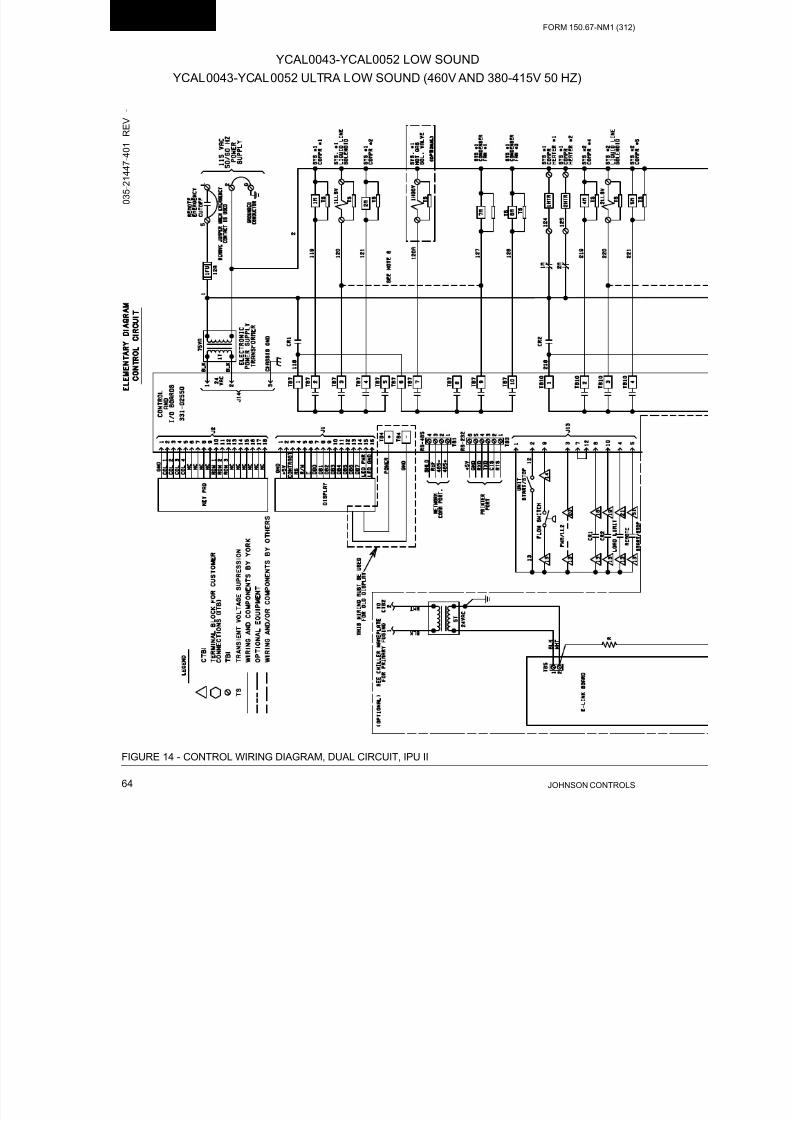
8/19/2019 Manual York
http://slidepdf.com/reader/full/manual-york 64/230JOHNSON CONTROLS64
FORM 150.67-NM1 (312)
Technical Data
FIGURE 14 - CONTROL WIRING DIAGRAM, DUAL CIRCUIT, IPU II
YCAL0043-YCAL0052 LOW SOUND
YCAL0043-YCAL0052 ULTRA LOW SOUND (460V AND 380-415V 50 HZ)
0 3 5 - 2 1 4 4 7 - 4
0 1
R E V
-

8/19/2019 Manual York
http://slidepdf.com/reader/full/manual-york 65/230
FORM 150.67-NM1 (312)
65JOHNSON CONTROLS

8/19/2019 Manual York
http://slidepdf.com/reader/full/manual-york 66/230JOHNSON CONTROLS66
FORM 150.67-NM1 (312)
Technical Data
YCAL0056-YCAL0066 LOW SOUND
YCAL0043-YCAL0052 ULTRA LOW SOUND (200V, 230V, 380V AND 575V)
0 3 5 - 2 1 5 8 6
- 4 0 1
R E V
-
FIGURE 15 - CONTROL WIRING DIAGRAM, DUAL CIRCUIT, IPU II

8/19/2019 Manual York
http://slidepdf.com/reader/full/manual-york 67/230
FORM 150.67-NM1 (312)
67JOHNSON CONTROLS

8/19/2019 Manual York
http://slidepdf.com/reader/full/manual-york 68/230JOHNSON CONTROLS68
FORM 150.67-NM1 (312)
Technical Data
YCAL0019-YCAL0022 LOW SOUND
YCAL0028-YCAL0033 ULTRA LOW SOUND
035-20964-103 REV C
Notes:
I. Field wiring to be in accordance with the current edition of the National Electrical Code as well as all other applicable codes and speci-
cations.
2. Contacts must be suitable for switching 24VDC, (gold contacts recommended). Wiring shall not be run in the same conduit with any
line voltage (class 1) wiring.
3. To cycle unit ON and OFF automatically with contact shown, install a cycling device in series with the ow switch. See note 2 for contact
rating and wiring specications.
4. To stop unit (emergency stop) with contacts other than those shown, install the stop contact between terminals 5 and 1. If a stop device
is not installed, a jumper must be connected between terminals 5 and 1. Device must have a minimum contact rating of 6A at 115VAC.
5. Contacts are rated at 115V, 100VA, resistive load only, and must be suppressed at load by user.
6. See installation, operation and maintenance manual when optional equipment is used.
7. Optional current readout. 5V = 200A.
8. 1MP thru 6MP are contained in their respective compressor junction boxes.
FIGURE 16 - CONTROL WIRING DIAGRAM, DETAILS, SINGLE CIRCUIT
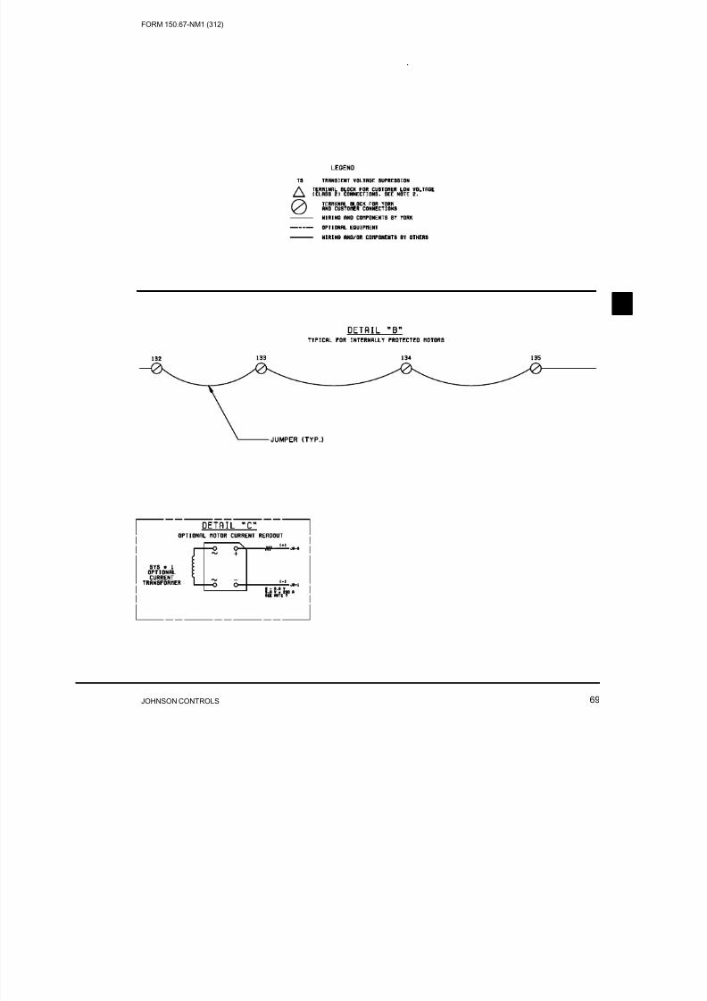
8/19/2019 Manual York
http://slidepdf.com/reader/full/manual-york 69/230
FORM 150.67-NM1 (312)
69JOHNSON CONTROLS

8/19/2019 Manual York
http://slidepdf.com/reader/full/manual-york 70/230JOHNSON CONTROLS70
FORM 150.67-NM1 (312)
Technical Data
YCAL0043-YCAL0052 LOW SOUND
YCAL0043-YCAL0052 ULTRA LOW SOUND
FIGURE 17 - CONTROL WIRING DIAGRAM, DETAILS, DUAL CIRCUIT
035-20880-103 REV C
Notes:
I. Field wiring to be in accordance with the current edition of the National Electrical Code as well as all other applicable codes and speci-
cations.
2. Contacts must be suitable for switching 24VDC, (gold contacts recommended). Wiring shall not be run in the same conduit with any
line voltage (class 1) wiring.
3. To cycle unit ON and OFF automatically with contact shown, install a cycling device in series with the ow switch. See note 2 for contact
rating and wiring specications.
4. To stop unit (emergency stop) with contacts other than those shown, install the stop contact between terminals 5 and 1. If a stop device
is not installed, a jumper must be connected between terminals 5 and 1. Device must have a minimum contact rating of 6A at 115VAC.
5. Contacts are rated at 115V, 100VA, resistive load only, and must be suppressed at load by user.
6. See installation, operation and maintenance manual when optional equipment is used.
7. Optional current readout. 5V = 200A.
8. 1MP thru 6MP are contained in their respective compressor junction boxes.

8/19/2019 Manual York
http://slidepdf.com/reader/full/manual-york 71/230
FORM 150.67-NM1 (312)
71JOHNSON CONTROLS

8/19/2019 Manual York
http://slidepdf.com/reader/full/manual-york 72/230JOHNSON CONTROLS72
FORM 150.67-NM1 (312)
Technical Data
FIGURE 18 - POWER WIRING, SINGLE CIRCUIT
YCAL0019-YCAL0022 LOW SOUND (200V, 230V, 380V, 460V AND 575V)
0 3 5 - 2 1 4 8 7 - 1 0 2
R E
V
A
POWER OPTIONS CONNECTION DIAGRAMS

8/19/2019 Manual York
http://slidepdf.com/reader/full/manual-york 73/230
FORM 150.67-NM1 (312)
73JOHNSON CONTROLS

8/19/2019 Manual York
http://slidepdf.com/reader/full/manual-york 74/230JOHNSON CONTROLS74
FORM 150.67-NM1 (312)
Technical Data
FIGURE 19 - POWER WIRING, SINGLE CIRCUIT
YCAL0019-YCAL0022 LOW SOUND (380-415V/3/50)
0 3 5 - 2 1 4 8 7 - 1 0 5
R E V
-

8/19/2019 Manual York
http://slidepdf.com/reader/full/manual-york 75/230
FORM 150.67-NM1 (312)
75JOHNSON CONTROLS

8/19/2019 Manual York
http://slidepdf.com/reader/full/manual-york 76/230JOHNSON CONTROLS76
FORM 150.67-NM1 (312)
Technical Data
FIGURE 20 - POWER WIRING, SINGLE CIRCUIT
YCAL0028-YCAL0033 LOW SOUND
YCAL0028-YCAL0033 ULTRA LOW SOUND (460V AND 380-415V/3/50)
0 3 5 - 2 1 4 7 2 -
1 0 2
R E V
B

8/19/2019 Manual York
http://slidepdf.com/reader/full/manual-york 77/230
FORM 150.67-NM1 (312)
77JOHNSON CONTROLS

8/19/2019 Manual York
http://slidepdf.com/reader/full/manual-york 78/230JOHNSON CONTROLS78
FORM 150.67-NM1 (312)
Technical Data
FIGURE 21 - POWER WIRING, SINGLE CIRCUIT
YCAL0028-YCAL0033 ULTRA LOW SOUND (200V, 230V, 380V AND 575V)
0 3 5 - 2 1 5 8 5 -
1 0 2
R E V
-

8/19/2019 Manual York
http://slidepdf.com/reader/full/manual-york 79/230
FORM 150.67-NM1 (312)
79JOHNSON CONTROLS

8/19/2019 Manual York
http://slidepdf.com/reader/full/manual-york 80/230JOHNSON CONTROLS80
FORM 150.67-NM1 (312)
Technical Data
YCAL0043-YCAL0052 LOW SOUND
YCAL0043-YCAL0052 ULTRA LOW SOUND (460V AND 380-415V 50 HZ)
0 3 5 - 2 1 4 4 7 - 1 0 2
R E V
A
FIGURE 22 - POWER WIRING, DUAL CIRCUIT

8/19/2019 Manual York
http://slidepdf.com/reader/full/manual-york 81/230
FORM 150.67-NM1 (312)
81JOHNSON CONTROLS

8/19/2019 Manual York
http://slidepdf.com/reader/full/manual-york 82/230JOHNSON CONTROLS82
FORM 150.67-NM1 (312)
Technical Data
FIGURE 23 - POWER WIRING, DUAL CIRCUIT
YCAL0056-YCAL0066 LOW SOUND
YCAL0043-YCAL0052 ULTRA LOW SOUND (200V, 230V, 380V AND 575V)
0 3 5 - 2 1 0 2 5 - 1 0 2
R E
V
B

8/19/2019 Manual York
http://slidepdf.com/reader/full/manual-york 83/230
FORM 150.67-NM1 (312)
83JOHNSON CONTROLS

8/19/2019 Manual York
http://slidepdf.com/reader/full/manual-york 84/230JOHNSON CONTROLS84
FORM 150.67-NM1 (312)
Technical Data
YCAL0019-YCAL0022 LOW SOUND (200V, 230V, 380V, 460V AND 575V)
0 3 5 - 2 1 4 8 7 -
4 0 4
R E V
-
FIGURE 24 - CONNECTION WIRING, SINGLE CIRCUIT
CONNECTION WIRING DIAGRAMS

8/19/2019 Manual York
http://slidepdf.com/reader/full/manual-york 85/230
FORM 150.67-NM1 (312)
85JOHNSON CONTROLS

8/19/2019 Manual York
http://slidepdf.com/reader/full/manual-york 86/230JOHNSON CONTROLS86
FORM 150.67-NM1 (312)
Technical Data
YCAL0019-YCAL0022 LOW SOUND (380-415V/3/50)
0 3 5 - 2 1 4 8 7 - 4 0 6
R E V
-
FIGURE 25 - CONNECTION WIRING, SINGLE CIRCUIT

8/19/2019 Manual York
http://slidepdf.com/reader/full/manual-york 87/230
FORM 150.67-NM1 (312)
87JOHNSON CONTROLS

8/19/2019 Manual York
http://slidepdf.com/reader/full/manual-york 88/230JOHNSON CONTROLS88
FORM 150.67-NM1 (312)
Technical Data
0 3 5 - 2 1 4 7 2 -
4 0 4
R E V
-
FIGURE 26 - CONNECTION WIRING, SINGLE CIRCUIT
YCAL0028-YCAL0033 LOW SOUND
YCAL0028-YCAL0033 ULTRA LOW SOUND (460V AND 380-415V/3/50)

8/19/2019 Manual York
http://slidepdf.com/reader/full/manual-york 89/230
FORM 150.67-NM1 (312)
89JOHNSON CONTROLS

8/19/2019 Manual York
http://slidepdf.com/reader/full/manual-york 90/230JOHNSON CONTROLS90
FORM 150.67-NM1 (312)
Technical Data
0 3 5 - 2 1 5 8 5 -
4 0 4
R E V
-
FIGURE 27 - CONNECTION WIRING, SINGLE CIRCUIT
YCAL0028-YCAL0033 ULTRA LOW SOUND (200V, 230V, 380V AND 575V)

8/19/2019 Manual York
http://slidepdf.com/reader/full/manual-york 91/230
FORM 150.67-NM1 (312)
91JOHNSON CONTROLS

8/19/2019 Manual York
http://slidepdf.com/reader/full/manual-york 92/230JOHNSON CONTROLS92
FORM 150.67-NM1 (312)
Technical Data
YCAL0043-YCAL0052 LOW SOUND
YCAL0043-YCAL0052 ULTRA LOW SOUND (460V AND 380-415V 50 HZ)
0 3 5 - 2 1 4 4 7 - 4 0 4
R E V
-
FIGURE 28 - CONNECTION WIRING, DUAL CIRCUIT

8/19/2019 Manual York
http://slidepdf.com/reader/full/manual-york 93/230
FORM 150.67-NM1 (312)
93JOHNSON CONTROLS

8/19/2019 Manual York
http://slidepdf.com/reader/full/manual-york 94/230JOHNSON CONTROLS94
FORM 150.67-NM1 (312)
Technical Data
FIGURE 29 - CONNECTION WIRING, DUAL CIRCUIT
YCAL0056-YCAL0066 LOW SOUND
YCAL0043-YCAL0052 ULTRA LOW SOUND (200V, 230V, 380V AND 575V)
0 3 5 - 2 1 5 8 6
- 4 0 4
R E V
-

8/19/2019 Manual York
http://slidepdf.com/reader/full/manual-york 95/230
FORM 150.67-NM1 (312)
95JOHNSON CONTROLS

8/19/2019 Manual York
http://slidepdf.com/reader/full/manual-york 96/230JOHNSON CONTROLS96
FORM 150.67-NM1 (312)
Technical Data
NOTE:
Placement on a level surface of free of obstructions (including snow, for winter operation) or air circulation ensures rated performance, reliable
operation, and ease of maintenance. Site restrictions may compromise minimum clearances indicated below, resulting in unpredictable airow
patterns and possible diminished performance. YORK’s unit controls will optimize operation without nuisance high-pressure safety cutouts;
however, the system designer must consider potential performance degradation. Recommended minimum clearances: front to wall – 6'; rear
to wall – 6'; cooler end to wall – 4'0"; coil end to wall – 6'; top – no obstructions allowed; distance between adjacent units – 10'. No more
than one adjacent wall may be higher than the unit. 1" nominal deection isolators (not shown) will increase overall unit height by 6".
DIMENSIONS – YCAL0019 (ENGLISH)
DIMENSIONS (ENGLISH)
LEFT END
6 3/4"
3 1/4"
3 15/16"
BOTTOM OF PANEL
7/8" TYP.
VIEW B-B
POWER: SINGLE POINT SUPPLY WITH TERMINAL BLOCK
46 1/16"
45 1/4"
11 5/8"
2" DIA
(2) 3.0 X 1.50
RIGGING HOLESBOTH ENDS
44 5/16"
BASE WIDTH
18 3/4"
11"TO ACCESS PANEL 16 1/4"
8 5/16"
12 13/16"
8 5/16"
12 13/16"
B B
2 1/4"
2" ANSI/AWWA C-606
CONN (typ)
OUT
IN

8/19/2019 Manual York
http://slidepdf.com/reader/full/manual-york 97/230
FORM 150.67-NM1 (312)
97JOHNSON CONTROLS
DIMENSIONS – YCAL0019 (ENGLISH) (CONT’D)
TOP VIEW
9/16" DIA MOUNTING HOLES(typ)
COMPR
END
1 1/16"
5"17"
2 1/4"ORIGIN
Y
CG X
44 3/8"
32 1/8"
6 1/8"
1 1/16"
CONTROL
PANEL
ENDEND CAP
WIDTH
FRONT VIEW
109 3/16"
RIGGING HOLES(2) 3.0 X 1.50
BOTH SIDES
15 5/8"
44 1/2"
74 1/2"
97 1/8"
(2) 7.0 X 2.25FORKLIFT HOLESBOTH SIDES
CG X
Z
2 1/4" 3 3/8"
13 3/4"
38 3/16"
9 1/16"
1"
CONTROL
PANEL

8/19/2019 Manual York
http://slidepdf.com/reader/full/manual-york 98/230JOHNSON CONTROLS98
FORM 150.67-NM1 (312)
Technical Data
DIMENSIONS – YCAL0022 (ENGLISH)
NOTE:
Placement on a level surface of free of obstructions (including snow, for winter operation) or air circulation ensures rated performance, reliable
operation, and ease of maintenance. Site restrictions may compromise minimum clearances indicated below, resulting in unpredictable airow
patterns and possible diminished performance. YORK’s unit controls will optimize operation without nuisance high-pressure safety cutouts;
however, the system designer must consider potential performance degradation. Recommended minimum clearances: front to wall – 6'; rear
to wall – 6'; cooler end to wall – 4'0"; coil end to wall – 6'; top – no obstructions allowed; distance between adjacent units – 10'. No more
than one adjacent wall may be higher than the unit. 1" nominal deection isolators (not shown) will increase overall unit height by 6".
LEFT END
6 3/4"
3 1/4"
3 15/16"
BOTTOM OF PANEL
7/8" TYP.
VIEW B-B
POWER: SINGLE POINT SUPPLY WITH TERMINAL BLOCK
46 1/16"
45 1/4"
11 5/8"
2" DIA
(2) 3.0 X 1.50
RIGGING HOLESBOTH ENDS
44 5/16"
BASE WIDTH
18 3/4"
11"TO ACCESS PANEL 16 1/4"
8 5/16"
12 13/16"
8 5/16"
12 13/16"
B B
2 1/4"
2" ANSI/AWWA C-606
CONN (typ)
IN
OUT

8/19/2019 Manual York
http://slidepdf.com/reader/full/manual-york 99/230
FORM 150.67-NM1 (312)
99JOHNSON CONTROLS
DIMENSIONS – YCAL0022 (ENGLISH) (CONT’D)
TOP VIEW
9/16" DIA MOUNTING HOLES(typ)
COMPR
END
1 1/16"
5"17"
2 1/4"ORIGIN
Y
CG X
44 3/8"
32 1/8"
6 1/8"
1 1/16"
CONTROL
PANEL
ENDEND CAP
WIDTH
FRONT VIEW
109 3/16"
RIGGING HOLES(2) 3.0 X 1.50
BOTH SIDES
15 5/8"
44 1/2"
74 1/2"
97 1/8"
(2) 7.0 X 2.25FORKLIFT HOLESBOTH SIDES
CG X
Z
2 1/4" 3 3/8"
13 3/4"
38 3/16"
9 1/16"
1"
CONTROL
PANEL

8/19/2019 Manual York
http://slidepdf.com/reader/full/manual-york 100/230JOHNSON CONTROLS100
FORM 150.67-NM1 (312)
Technical Data
DIMENSIONS – YCAL0028 (ENGLISH)
NOTE:
Placement on a level surface of free of obstructions (including snow, for winter operation) or air circulation ensures rated performance, reliable
operation, and ease of maintenance. Site restrictions may compromise minimum clearances indicated below, resulting in unpredictable airow
patterns and possible diminished performance. YORK’s unit controls will optimize operation without nuisance high-pressure safety cutouts;
however, the system designer must consider potential performance degradation. Recommended minimum clearances: front to wall – 6'; rear
to wall – 6'; cooler end to wall – 4'0"; coil end to wall – 6'; top – no obstructions allowed; distance between adjacent units – 10'. No more
than one adjacent wall may be higher than the unit. 1" nominal deection isolators (not shown) will increase overall unit height by 6".

8/19/2019 Manual York
http://slidepdf.com/reader/full/manual-york 101/230
FORM 150.67-NM1 (312)
101JOHNSON CONTROLS
DIMENSIONS – YCAL0028 (ENGLISH) (CONT’D)
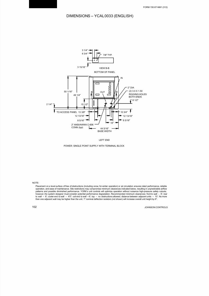
8/19/2019 Manual York
http://slidepdf.com/reader/full/manual-york 102/230JOHNSON CONTROLS102
FORM 150.67-NM1 (312)
Technical Data
NOTE:
Placement on a level surface of free of obstructions (including snow, for winter operation) or air circulation ensures rated performance, reliable
operation, and ease of maintenance. Site restrictions may compromise minimum clearances indicated below, resulting in unpredictable airow
patterns and possible diminished performance. YORK’s unit controls will optimize operation without nuisance high-pressure safety cutouts;
however, the system designer must consider potential performance degradation. Recommended minimum clearances: front to wall – 6'; rear
to wall – 6'; cooler end to wall – 4'0"; coil end to wall – 6'; top – no obstructions allowed; distance between adjacent units – 10'. No more
than one adjacent wall may be higher than the unit. 1" nominal deection isolators (not shown) will increase overall unit height by 6".
DIMENSIONS – YCAL0033 (ENGLISH)
44 5/16"
BASE WIDTH
50 1/16"
49 1/4"
6 3/4"
3 1/4"
3 15/16"
LEFT END
BOTTOM OF PANEL
7/8" TYP.
VIEW B-B
POWER: SINGLE POINT SUPPLY WITH TERMINAL BLOCK
19"
10 3/4"
8 1/2"
2" ANSI/AWWA C-606
CONN (typ)
B B
15 1/2"
TO ACCESS PANEL 13 3/8"
2 1/4"
8 5/16"
12 13/16"
8 5/16"
12 13/16"
2" DIA
(2) 3.0 X 1.50
RIGGING HOLESBOTH ENDS
IN
OUT

8/19/2019 Manual York
http://slidepdf.com/reader/full/manual-york 103/230
FORM 150.67-NM1 (312)
103JOHNSON CONTROLS
DIMENSIONS – YCAL0033 (ENGLISH) (CONT’D)
2 1/4"3 3/8"
17 3/4"
42 1/8"
9"
44 3/8"
32 1/8"
15 5/8"
50 1/2"
80 1/2"
105 1/16"
6 1/8"
1"
1 1/16"
1 1/16"
5"17"
FRONT VIEW
TOP VIEW
9/16" DIA MOUNTING HOLES(typ)
CONTROL
PANEL
CONTROL
PANEL
END
COMPR
END
ORIGIN
Y
CG X
CG X
Z
END CAP
WIDTH
118 5/16"
RIGGING HOLES
(2) 7.0 X 2.25
FORKLIFT HOLESBOTH SIDES (2) 3.0 X 1.50
BOTH SIDES
1 7/8"

8/19/2019 Manual York
http://slidepdf.com/reader/full/manual-york 104/230JOHNSON CONTROLS104
FORM 150.67-NM1 (312)
Technical Data
NOTE:
Placement on a level surface of free of obstructions (including snow, for winter operation) or air circulation ensures rated performance, reliable
operation, and ease of maintenance. Site restrictions may compromise minimum clearances indicated below, resulting in unpredictable airow
patterns and possible diminished performance. YORK’s unit controls will optimize operation without nuisance high-pressure safety cutouts;
however, the system designer must consider potential performance degradation. Recommended minimum clearances: front to wall – 6'; rear
to wall – 6'; cooler end to wall – 4'0"; coil end to wall – 6'; top – no obstructions allowed; distance between adjacent units – 10'. No more
than one adjacent wall may be higher than the unit. 1" nominal deection isolators (not shown) will increase overall unit height by 6".
DIMENSIONS – YCAL0043 (ENGLISH)
VIEW B-B3 15/16"
3 1/4"
6 3/4"
BOTTOM OF PANEL
7/8" TYP.
47 3/4"
46 15/16"
45 1/8"
12 5/8"3" ANSI/AWWA
C-606 (typ)
90 1/4" BASE WIDTH
LEFT END
LIQUID OUT
34 5/8"
15 3/4"
9 15/16"
ELECTRICAL ACCESS
PANEL
LIQUID IN

8/19/2019 Manual York
http://slidepdf.com/reader/full/manual-york 105/230
FORM 150.67-NM1 (312)
105JOHNSON CONTROLS
DIMENSIONS – YCAL0043 (ENGLISH) (CONT’D)
90 9/16"
45 5/16"
Y
CGX
1 1/16"
ORIGIN
END CAP
WIDTH
21 13/16" TOP VIEW
9 13/16"
1 1/
9 13
9/16" DIA MOUNTING HOLES(typ)
144 13/16"
15 1/16" 13 15/16"
TWO LIFTING HOLES
BOTH SIDES
FRONT VIEWCG
X
Z
38"
5 5/16"
25 3/8"
13 5/8"
B B
COIL
ENDCOOLER
END
CONTROL PANEL

8/19/2019 Manual York
http://slidepdf.com/reader/full/manual-york 106/230JOHNSON CONTROLS106
FORM 150.67-NM1 (312)
Technical Data
NOTE:
Placement on a level surface of free of obstructions (including snow, for winter operation) or air circulation ensures rated performance, reliable
operation, and ease of maintenance. Site restrictions may compromise minimum clearances indicated below, resulting in unpredictable airow
patterns and possible diminished performance. YORK’s unit controls will optimize operation without nuisance high-pressure safety cutouts;
however, the system designer must consider potential performance degradation. Recommended minimum clearances: front to wall – 6'; rear
to wall – 6'; cooler end to wall – 4'0"; coil end to wall – 6'; top – no obstructions allowed; distance between adjacent units – 10'. No more
than one adjacent wall may be higher than the unit. 1" nominal deection isolators (not shown) will increase overall unit height by 6".
DIMENSIONS – YCAL0046 (ENGLISH)
VIEW B-B
3 15/16"
3 1/4"
6 3/4"
BOTTOM OF PANEL
7/8" TYP.
47 3/4"
46 15/16"
45 1/8"
12 5/8"3" ANSI/AWWA C-606(typ)
90 1/4" BASE WIDTH
LEFT END
LIQUID OUT
34 5/8"
15 3/4"
9 15/16"
ELECTRICAL ACCESS
PANEL
LIQUID IN

8/19/2019 Manual York
http://slidepdf.com/reader/full/manual-york 107/230
FORM 150.67-NM1 (312)
107JOHNSON CONTROLS
DIMENSIONS – YCAL0046 (ENGLISH) (CONT’D)
90 9/16"
45 5/16"
Y
CGX
1 1/16"
ORIGIN
END CAP
WIDTH
20 1/16" TOP VIEW
9 13/16"
1 1/16
9 13/1
9/16" DIA MOUNTING HOLES(typ)
144 13/16"
15 1/16"13 15/16"
TWO LIFTING HOLES
BOTH SIDES
FRONT VIEWCG
X
Z
38"
5 5/16"
25 3/8"
13 5/8"
B B
COIL
ENDCOOLER
END
CONTROL PANEL
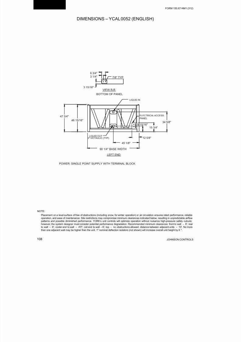
8/19/2019 Manual York
http://slidepdf.com/reader/full/manual-york 108/230JOHNSON CONTROLS108
FORM 150.67-NM1 (312)
Technical Data
NOTE:
Placement on a level surface of free of obstructions (including snow, for winter operation) or air circulation ensures rated performance, reliable
operation, and ease of maintenance. Site restrictions may compromise minimum clearances indicated below, resulting in unpredictable airow
patterns and possible diminished performance. YORK’s unit controls will optimize operation without nuisance high-pressure safety cutouts;
however, the system designer must consider potential performance degradation. Recommended minimum clearances: front to wall – 6'; rear
to wall – 6'; cooler end to wall – 4'0"; coil end to wall – 6'; top – no obstructions allowed; distance between adjacent units – 10'. No more
than one adjacent wall may be higher than the unit. 1" nominal deection isolators (not shown) will increase overall unit height by 6 ".
DIMENSIONS – YCAL0052 (ENGLISH)

8/19/2019 Manual York
http://slidepdf.com/reader/full/manual-york 109/230
FORM 150.67-NM1 (312)
109JOHNSON CONTROLS
DIMENSIONS – YCAL0052 (ENGLISH) (CONT’D)

8/19/2019 Manual York
http://slidepdf.com/reader/full/manual-york 110/230JOHNSON CONTROLS110
FORM 150.67-NM1 (312)
Technical Data
NOTE:
Placement on a level surface of free of obstructions (including snow, for winter operation) or air circulation ensures rated performance, reliable
operation, and ease of maintenance. Site restrictions may compromise minimum clearances indicated below, resulting in unpredictable airow
patterns and possible diminished performance. YORK’s unit controls will optimize operation without nuisance high-pressure safety cutouts;
however, the system designer must consider potential performance degradation. Recommended minimum clearances: front to wall – 6'; rear
to wall – 6'; cooler end to wall – 4'0"; coil end to wall – 6'; top – no obstructions allowed; distance between adjacent units – 10'. No more
than one adjacent wall may be higher than the unit. 1" nominal deection isolators (not shown) will increase overall unit height by 6".
DIMENSIONS – YCAL0056 (ENGLISH)

8/19/2019 Manual York
http://slidepdf.com/reader/full/manual-york 111/230
FORM 150.67-NM1 (312)
111JOHNSON CONTROLS
DIMENSIONS – YCAL0056 (ENGLISH) (CONT’D)

8/19/2019 Manual York
http://slidepdf.com/reader/full/manual-york 112/230JOHNSON CONTROLS112
FORM 150.67-NM1 (312)
Technical Data
DIMENSIONS – YCAL0066 (ENGLISH)
NOTE:
Placement on a level surface of free of obstructions (including snow, for winter operation) or air circulation ensures rated performance, reliable
operation, and ease of maintenance. Site restrictions may compromise minimum clearances indicated below, resulting in unpredictable airow
patterns and possible diminished performance. YORK’s unit controls will optimize operation without nuisance high-pressure safety cutouts;
however, the system designer must consider potential performance degradation. Recommended minimum clearances: front to wall – 6'; rear
to wall – 6'; cooler end to wall – 4'0"; coil end to wall – 6'; top – no obstructions allowed; distance between adjacent units – 10'. No more
than one adjacent wall may be higher than the unit. 1" nominal deection isolators (not shown) will increase overall unit height by 6".
62 5/8"
61 7/8"
34 11/16"
15 3/4"
9 15/16"
43 1/8"
12 5/8"
3" ANSI/AWWA C-606
(typ)
ELECTRICAL ACCESS
PANEL
90 1/4" BASE WIDTH
LEFT END
LIQUID OUT
LIQUID IN
VIEW B-B
7/8" TYP.
3 15/16"
3 1/4"
6 3/4"
BOTTOM OF PANEL

8/19/2019 Manual York
http://slidepdf.com/reader/full/manual-york 113/230
FORM 150.67-NM1 (312)
113JOHNSON CONTROLS
DIMENSIONS – YCAL0066 (ENGLISH) (CONT’D)
90 9/16"
43 5/16"
16 11/16"
38"
5 3/16"
153 5/8"
15 1/16"16"
25 3/8"
28 9/16"
CONTROL
PANEL
TWO LIFTING HOLES
BOTH SIDES
Y
TOP VIEW
CGX
FRONT VIEWCG
X
Z
1 1/16"
1 1/16
ORIGIN 9 13/16" 9 13/16
B B
9/16" DIA MOUNTING HOLES(typ)
END CAP
WIDTH
COIL
ENDCOOLER
END

8/19/2019 Manual York
http://slidepdf.com/reader/full/manual-york 114/230JOHNSON CONTROLS114
FORM 150.67-NM1 (312)
Technical Data
NOTE:
Placement on a level surface of free of obstructions (including snow, for winter operation) or air circulation ensures rated performance, reliable
operation, and ease of maintenance. Site restrictions may compromise minimum clearances indicated below, resulting in unpredictable airow
patterns and possible diminished performance. YORK’s unit controls will optimize operation without nuisance high-pressure safety cutouts;
however, the system designer must consider potential performance degradation. Recommended minimum clearances: front to wall – 2m; rear
to wall – 2m; cooler end to wall – 1.2m; coil end to wall – 2m; top – no obstructions allowed; distance between adjacent units – 3m. No more
than one adjacent wall may be higher than the unit. 1" nominal deection isolators (not shown) will increase overall unit height by 152mm.
All dimensions are in mm unless specied otherwise.
DIMENSIONS – YCAL0019 (SI)
LEFT END
171
82
100
BOTTOM OF PANEL
22 TYP.
VIEW B-B
POWER: SINGLE POINT SUPPLY WITH TERMINAL BLOCK
1170
1149
295
51 DIA
(2) 76 X 38
RIGGING HOLESBOTH ENDS
1126
BASE WIDTH
477
280TO ACCESS PANEL 412
211
325
211
325
B B
58
51 ANSI/AWWA C-606
CONN (typ)
IN
OUT

8/19/2019 Manual York
http://slidepdf.com/reader/full/manual-york 115/230
FORM 150.67-NM1 (312)
115JOHNSON CONTROLS
DIMENSIONS – YCAL0019 (SI) (CONT’D)
TOP VIEW
14 DIA MOUNTING HOLES(typ)
COMPR
END
28
126431
58ORIGIN
Y
CG X
1128
815
156
28
CONTROL
PANEL
ENDEND CAP
WIDTH
FRONT VIEW
2774
RIGGING HOLES
(2) 76 X 38
BOTH SIDES
398
1130
1892
2466
(2) 178 X 57FORKLIFT HOLESBOTH SIDES
CG X
Z
58 86
350
970
230
25
CONTROL
PANEL

8/19/2019 Manual York
http://slidepdf.com/reader/full/manual-york 116/230JOHNSON CONTROLS116
FORM 150.67-NM1 (312)
Technical Data
NOTE:
Placement on a level surface of free of obstructions (including snow, for winter operation) or air circulation ensures rated performance, reliable
operation, and ease of maintenance. Site restrictions may compromise minimum clearances indicated below, resulting in unpredictable airow
patterns and possible diminished performance. YORK’s unit controls will optimize operation without nuisance high-pressure safety cutouts;
however, the system designer must consider potential performance degradation. Recommended minimum clearances: front to wall – 2m; rear
to wall – 2m; cooler end to wall – 1.2m; coil end to wall – 2m; top – no obstructions allowed; distance between adjacent units – 3m. No more
than one adjacent wall may be higher than the unit. 1" nominal deection isolators (not shown) will increase overall unit height by 152mm.
DIMENSIONS – YCAL0022 (SI)
LEFT END
171
82
100
BOTTOM OF PANEL
22 TYP.
VIEW B-B
POWER: SINGLE POINT SUPPLY WITH TERMINAL BLOCK
1170
1149
295
51 DIA
(2) 76 X 38
RIGGING HOLESBOTH ENDS
1126
BASE WIDTH
477
280TO ACCESS PANEL 412
211
325
211
325
B B
58
51 VICTAULIC CONN
(typ)
IN
OUT
All dimensions are in mm unless specied otherwise.

8/19/2019 Manual York
http://slidepdf.com/reader/full/manual-york 117/230
FORM 150.67-NM1 (312)
117JOHNSON CONTROLS
DIMENSIONS – YCAL0022 (SI) (CONT’D)
TOP VIEW
14 DIA MOUNTING HOLES(typ)
COMPR
END
28
126431
58ORIGIN
Y
CG X
1128
815
156
28
CONTROL
PANEL
ENDEND CAP
WIDTH
FRONT VIEW
2774
RIGGING HOLES(2) 76 X 38
BOTH SIDES
398
1130
1892
2466
(2) 178 X 57FORKLIFT HOLESBOTH SIDES
CG X
Z
58 86
350
970
230
25
CONTROL PANEL
328 530
512 317
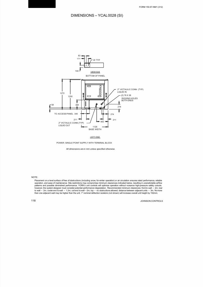
8/19/2019 Manual York
http://slidepdf.com/reader/full/manual-york 118/230JOHNSON CONTROLS118
FORM 150.67-NM1 (312)
Technical Data
NOTE:
Placement on a level surface of free of obstructions (including snow, for winter operation) or air circulation ensures rated performance, reliable
operation, and ease of maintenance. Site restrictions may compromise minimum clearances indicated below, resulting in unpredictable airow
patterns and possible diminished performance. YORK’s unit controls will optimize operation without nuisance high-pressure safety cutouts;
however, the system designer must consider potential performance degradation. Recommended minimum clearances: front to wall – 2m; rear
to wall – 2m; cooler end to wall – 1.2m; coil end to wall – 2m; top – no obstructions allowed; distance between adjacent units – 3m. No more
than one adjacent wall may be higher than the unit. 1" nominal deection isolators (not shown) will increase overall unit height by 152mm.
DIMENSIONS – YCAL0028 (SI)
All dimensions are in mm unless specied otherwise.

8/19/2019 Manual York
http://slidepdf.com/reader/full/manual-york 119/230
FORM 150.67-NM1 (312)
119JOHNSON CONTROLS
DIMENSIONS – YCAL0028 (SI) (CONT’D)
5886
450
1070
229
1128
815
398
1282
2044
2669
156
25
28
28
126431
CONTROL
PANEL
COMPR
END
ORIGIN
Y
CG X
END CAP
WIDTH
3005
RIGGING HOLES
(2) 178 X 57
FORKLIFT HOLESBOTH SIDES (2) 76 X 38
BOTH SIDES
47
R-410A CHILLER
FRONT VIEW
TOP VIEW
495 456
423460
16 DIA MOUNTING HOLES(TYP)
CONTROL
PANEL
END

8/19/2019 Manual York
http://slidepdf.com/reader/full/manual-york 120/230JOHNSON CONTROLS120
FORM 150.67-NM1 (312)
Technical Data
NOTE:
Placement on a level surface of free of obstructions (including snow, for winter operation) or air circulation ensures rated performance, reliable
operation, and ease of maintenance. Site restrictions may compromise minimum clearances indicated below, resulting in unpredictable airow
patterns and possible diminished performance. YORK’s unit controls will optimize operation without nuisance high-pressure safety cutouts;
however, the system designer must consider potential performance degradation. Recommended minimum clearances: front to wall – 2m; rear
to wall – 2m; cooler end to wall – 1.2m; coil end to wall – 2m; top – no obstructions allowed; distance between adjacent units – 3m. No more
than one adjacent wall may be higher than the unit. 1" nominal deection isolators (not shown) will increase overall unit height by 152mm.
DIMENSIONS – YCAL0033 (SI)
1126
BASE WIDTH
1272
1250
171
82
100
LEFT END
BOTTOM OF PANEL
22 TYP.
VIEW B-B
POWER: SINGLE POINT SUPPLY WITH TERMINAL BLOCK
483
274
216
51 VICTAULIC CONN
(typ)
B B
394
TO ACCESS PANEL 340
58
211
325
211
325
51 DIA
(2) 76 X 38
RIGGING HOLESBOTH ENDS
IN
OUT
All dimensions are in mm unless specied otherwise.

8/19/2019 Manual York
http://slidepdf.com/reader/full/manual-york 121/230
FORM 150.67-NM1 (312)
121JOHNSON CONTROLS
DIMENSIONS – YCAL0033 (SI) (CONT’D)
5886
450
1070
229
1128
815
398
1282
2044
2669
156
25
28
28
126431
FRONT VIEW
TOP VIEW
14 DIA MOUNTING HOLES(typ)
CONTROL PANEL
CONTROL
PANEL
END
COMPR
END
ORIGIN
Y
CG X
CG X
Z
END CAP
WIDTH
3005
RIGGING HOLES
(2) 178 X 57
FORKLIFT HOLESBOTH SIDES (2) 76 X 38
BOTH SIDES
47

8/19/2019 Manual York
http://slidepdf.com/reader/full/manual-york 122/230JOHNSON CONTROLS122
FORM 150.67-NM1 (312)
Technical Data
NOTE:
Placement on a level surface of free of obstructions (including snow, for winter operation) or air circulation ensures rated performance, reliable
operation, and ease of maintenance. Site restrictions may compromise minimum clearances indicated below, resulting in unpredictable airow
patterns and possible diminished performance. YORK’s unit controls will optimize operation without nuisance high-pressure safety cutouts;
however, the system designer must consider potential performance degradation. Recommended minimum clearances: front to wall – 2m; rear
to wall – 2m; cooler end to wall – 1.2m; coil end to wall – 2m; top – no obstructions allowed; distance between adjacent units – 3m. No more
than one adjacent wall may be higher than the unit. 1" nominal deection isolators (not shown) will increase overall unit height by 152mm.
DIMENSIONS – YCAL0043 (SI)
VIEW B-B100
82
171
BOTTOM OF PANEL
22 TYP.
1213
1192
1146
321
76 VICTAULIC (typ)
2292 BASE WIDTH
LEFT END
LIQUID OUT
879
401252
ELECTRICAL ACCESS
PANEL
LIQUID IN
All dimensions are in mm unless specied otherwise.

8/19/2019 Manual York
http://slidepdf.com/reader/full/manual-york 123/230
FORM 150.67-NM1 (312)
123JOHNSON CONTROLS
DIMENSIONS – YCAL0043 (SI) (CONT’D)
2301
1150
Y
CG X
28
END CAP
WIDTH
ORIGIN
554 TOP VIEW
249
28
249
14 DIA MOUNTING HOLES(typ)
3678
383355
TWO LIFTING HOLES
BOTH SIDES
FRONT VIEWCGX
Z
965
135
645
346
B B
COILEND
COOLEREND
CONTROL PANEL

8/19/2019 Manual York
http://slidepdf.com/reader/full/manual-york 124/230JOHNSON CONTROLS124
FORM 150.67-NM1 (312)
Technical Data
NOTE:
Placement on a level surface of free of obstructions (including snow, for winter operation) or air circulation ensures rated performance, reliable
operation, and ease of maintenance. Site restrictions may compromise minimum clearances indicated below, resulting in unpredictable airow
patterns and possible diminished performance. YORK’s unit controls will optimize operation without nuisance high-pressure safety cutouts;
however, the system designer must consider potential performance degradation. Recommended minimum clearances: front to wall – 2m; rear
to wall – 2m; cooler end to wall – 1.2m; coil end to wall – 2m; top – no obstructions allowed; distance between adjacent units – 3m. No more
than one adjacent wall may be higher than the unit. 1" nominal deection isolators (not shown) will increase overall unit height by 152mm.
NOTE: All dimensions are in mm unless specied otherwise.
DIMENSIONS – YCAL0046 (SI)
VIEW B-B100
82
171
BOTTOM OF PANEL
22 TYP.
1213
1192
1146
321
76 VICTAULIC (typ)
2292 BASE WIDTH
LEFT END
LIQUID OUT
879
401252
ELECTRICAL ACCESS
PANEL
LIQUID IN
All dimensions are in mm unless specied otherwise.

8/19/2019 Manual York
http://slidepdf.com/reader/full/manual-york 125/230
FORM 150.67-NM1 (312)
125JOHNSON CONTROLS
DIMENSIONS – YCAL0046 (SI) (CONT’D)
2301
1150
Y
CG
X
28
ORIGIN
END CAP
WIDTH
509 TOP VIEW
249
28
249
14 DIA MOUNTING HOLES(typ)
3678
383355
TWO LIFTING HOLES
BOTH SIDES
FRONT VIEWCGX
Z
965
135
645
346
B B
COILEND
COOLEREND
CONTROL PANEL

8/19/2019 Manual York
http://slidepdf.com/reader/full/manual-york 126/230JOHNSON CONTROLS126
FORM 150.67-NM1 (312)
Technical Data
NOTE:
Placement on a level surface of free of obstructions (including snow, for winter operation) or air circulation ensures rated performance, reliable
operation, and ease of maintenance. Site restrictions may compromise minimum clearances indicated below, resulting in unpredictable airow
patterns and possible diminished performance. YORK’s unit controls will optimize operation without nuisance high-pressure safety cutouts;
however, the system designer must consider potential performance degradation. Recommended minimum clearances: front to wall – 2m; rear
to wall – 2m; cooler end to wall – 1.2m; coil end to wall – 2m; top – no obstructions allowed; distance between adjacent units – 3m. No more
than one adjacent wall may be higher than the unit. 1" nominal deection isolators (not shown) will increase overall unit height by 152mm.
DIMENSIONS – YCAL0052 (SI)
All dimensions are in mm unless specied otherwise.

8/19/2019 Manual York
http://slidepdf.com/reader/full/manual-york 127/230
FORM 150.67-NM1 (312)
127JOHNSON CONTROLS
DIMENSIONS – YCAL0052 (SI) (CONT’D)

8/19/2019 Manual York
http://slidepdf.com/reader/full/manual-york 128/230JOHNSON CONTROLS128
FORM 150.67-NM1 (312)
Technical Data
NOTE:
Placement on a level surface of free of obstructions (including snow, for winter operation) or air circulation ensures rated performance, reliable
operation, and ease of maintenance. Site restrictions may compromise minimum clearances indicated below, resulting in unpredictable airow
patterns and possible diminished performance. YORK’s unit controls will optimize operation without nuisance high-pressure safety cutouts;
however, the system designer must consider potential performance degradation. Recommended minimum clearances: front to wall – 2m; rear
to wall – 2m; cooler end to wall – 1.2m; coil end to wall – 2m; top – no obstructions allowed; distance between adjacent units – 3m. No more
than one adjacent wall may be higher than the unit. 1" nominal deection isolators (not shown) will increase overall unit height by 152mm.
DIMENSIONS – YCAL0056 (SI)
All dimensions are in mm unless specied otherwise.

8/19/2019 Manual York
http://slidepdf.com/reader/full/manual-york 129/230
FORM 150.67-NM1 (312)
129JOHNSON CONTROLS
DIMENSIONS – YCAL0056 (SI) (CONT’D)

8/19/2019 Manual York
http://slidepdf.com/reader/full/manual-york 130/230JOHNSON CONTROLS130
FORM 150.67-NM1 (312)
Technical Data
DIMENSIONS – YCAL0066 (SI)
NOTE:
Placement on a level surface of free of obstructions (including snow, for winter operation) or air circulation ensures rated performance, reliable
operation, and ease of maintenance. Site restrictions may compromise minimum clearances indicated below, resulting in unpredictable airow
patterns and possible diminished performance. YORK’s unit controls will optimize operation without nuisance high-pressure safety cutouts;
however, the system designer must consider potential performance degradation. Recommended minimum clearances: front to wall – 2m; rear
to wall – 2m; cooler end to wall – 1.2m; coil end to wall – 2m; top – no obstructions allowed; distance between adjacent units – 3m. No more
than one adjacent wall may be higher than the unit. 1" nominal deection isolators (not shown) will increase overall unit height by 152mm.
1590
1572
880
401
252
1095
321
76 VICTAULIC (typ)
ELECTRICAL ACCESS
PANEL
2292 BASE WIDTH
LEFT END
LIQUID OUT
LIQUID IN
VIEW B-B
22 TYP.
100
82171
BOTTOM OF PANEL
All dimensions are in mm unless specied otherwise.

8/19/2019 Manual York
http://slidepdf.com/reader/full/manual-york 131/230
FORM 150.67-NM1 (312)
131JOHNSON CONTROLS
DIMENSIONS – YCAL0066 (SI) (CONT’D)
2301
1100
424
965
131
3902
383 406
645
726
CONTROL
PANEL
TWO LIFTING HOLES
BOTH SIDES
Y
TOP VIEW
CGX
FRONT VIEWCG
X
Z
28
28
ORIGIN249 249
B B
14 DIA MOUNTING HOLES(typ)
END CAP
WIDTH
COILEND
COOLEREND

8/19/2019 Manual York
http://slidepdf.com/reader/full/manual-york 132/230JOHNSON CONTROLS132
FORM 150.67-NM1 (312)
Technical Data
TECHNICAL DATA – CLEARANCES
(1.3 m) (2 m)
( 2 m )
( 2 m )
NOTES:
1. No obstructions allowed above the unit.
2. Only one adjacent wall may be higher than the unit.
3. Adjacent units should be 10 feet (3 Meters) apart.
LD10506
FIGURE 30 - UNIT CLEARANCES – ALL MODELS

8/19/2019 Manual York
http://slidepdf.com/reader/full/manual-york 133/230
FORM 150.67-NM1 (312)
133JOHNSON CONTROLS
General
Weights of specific chiller models vary significantly as
options are added. As a result, total weights, weights atindividual isolator positions, and actual isolator selec-
tion at each position cannot be published due to the
vast number of possible combinations. This informa-
tion will be available when the specific chiller/ option
selection is made from the local YORK sales office.
Be aware, weights may change with each option along
with possible isolator changes. Weights and isolators
may need to be recalculated when the option selections
are changed.
Whenever the isolator option is ordered, the isolators
will be shipped loose with the chiller. Packed withthe isolators and also in the control panel informa-
tion packet is a drawing and table specifically for each
chiller, based on the option selection. The drawing
and table will be similar to the ones shown below. The
drawing will show the isolator locations along with the
weight in pounds and kilograms at the specific loca-
tion, isolator position, and location measurements for
each isolator.
WEIGHT DISTRIBUTION AND ISOLATOR MOUNTING POSITIONS
YCAL0019 – 0033 (WITHOUT PUMP PACKAGE OPTION)
LOCATIONX DISTANCE
INCHES / MM
Y DISTANCE
INCHES / MMVENDOR NUMBER
OPERATING
WEIGHT
LBS / (KG)
R1 43.22 (1097.8) 4.94 (125.5) CIP-B-450 / RED 276 (125.2)
L1 1.09 (27.7) 4.94 (125.5 CIP-B-450 / RED 284 (128.8)
R2 43.22 (1097.8) 92.25 (2343.2)CIP-B-276750 /
WHITE407 (184.6)
L2 1.09 (27.7) 92.25 2343.2) CIP-B-750 / WHITE 418 (189.6)
“ SAMPLE PRINTOUT” TYPICAL OF THE INFORMATION SUPPLIED IN THE ISOLATOR PACKA GE AND IN THE CHILLER
PANEL LITERATURE PACKET
Order No: 069528190101
Line No: 1UNIT SHIPPING WT.
(DISPLAY ON UNIT DATA
NAMEPLATE)
KG LBS
617 1361
ISOLATOR LOCATIONS
L1
L2
R1
R2
CONTROL
PANEL END
Y
CG X
ISOLATORS

8/19/2019 Manual York
http://slidepdf.com/reader/full/manual-york 134/230JOHNSON CONTROLS134
FORM 150.67-NM1 (312)
Technical Data
STANDARD ALUMINUM CONDENSER FINS OPTIONAL COPPER CONDENSER FINS
LOCATION L1 L2 R1 R2 L1 L2 R1 R2
YCAL0019
1”
DeectionCIP-B-450 CIP-B-750 CIP-B-450 CIP-B-750 CIP-B-450 CIP-B-750 CIP-B-450 CIP-B-750
Neoprene ND-C ND-C ND-C ND-C ND-C ND-C ND-C ND-C
SeismicSLRS-
2-C2-420
SLRS-
2-C2-660
SLRS-
2-C2-420
SLRS-
2-C2-660
SLRS-
2-C2-420
SLRS-2-
C2-660
SLRS-2-
C2-420
SLRS-
2-C2-660
YCAL0022
1”
DeectionCIP-B-450 CIP-B-750 CIP-B-450 CIP-B-750 CIP-B-450 CIP-B-750 CIP-B-450 CIP-B-750
Neoprene ND-C ND-C ND-C ND-C ND-C ND-C ND-C ND-C
SeismicSLRS-
2-C2-420
SLRS-
2-C2-660
SLRS-
2-C2-420
SLRS-
2-C2-660
SLRS-2
-C2-520
SLRS-2-
C2-660
SLRS-2-
C2-520
SLRS-2-
C2-660
YCAL0028
1”Deection
CIP-B-450 CIP-B-1000 CIP-B-450 CIP-B-750 CIP-B-750 CIP-B-1000 CIP-B-750 CIP-B-1000
Neoprene ND-C ND-C ND-C ND-C ND-C ND-C ND-C ND-C
SeismicSLRS-
2-C2-520
SLRS-
2-C2-920
SLRS-
2-C2-520
SLRS-
2-C2-920
SLRS-
2-C2-520
SLRS-2-
C2-920
SLRS-2-
C2-520
SLRS-2-
C2-920
YCAL0033
1”
DeectionCIP-B-450 CIP-B-1000 CIP-B-450 CIP-B-1000 CIP-B-750 CIP-B-1000 CIP-B-750 CIP-B-1000
Neoprene ND-C ND-C ND-C ND-C ND-C ND-C ND-C ND-C
SeismicSLRS-
2-C2-520
SLRS-
2-C2-920
SLRS-
2-C2-520
SLRS-
2-C2-920
SLRS-
2-C2-520
SLRS-2-
C2-920
SLRS-2-
C2-520
SLRS-2-
C2-920
ISOLATOR SELECTION
YCAL0019 – 0033 (WITHOUT PUMP PACKAGE OPTION)
NOTE: Isolators are selected using a service factor.
CONTROL
PANEL
END
YCAL0019, 0022, 0033
L1 L2
R1 R2
SAMPLE
YCAL0019, 0022, 028, 0033
CONTROL
PANEL
END

8/19/2019 Manual York
http://slidepdf.com/reader/full/manual-york 135/230
FORM 150.67-NM1 (312)
135JOHNSON CONTROLS
WEIGHT DISTRIBUTION AND ISOLATOR MOUNTING POSITIONS
YCAL0043 – 0066
General
Weights of specific chiller models vary significantly as
options are added. As a result, total weights, weights at
individual isolator positions, and actual isolator selec-tion at each position cannot be published due to the
vast number of possible combinations. This informa-
tion will be available when the specific chiller/ option
selection is made from the local YORK sales office.
Be aware, weights will change with each option along
with possible isolator changes. Weights and isolators
may need to be recalculated when the option selections
are changed.
Whenever the isolator option is ordered, the isolators
will be shipped loose with the chiller. Packed with
the isolators and also in the control panel informa-
tion packet is a drawing and table specifically for each
chiller, based on the option selection. The drawing
and table will be similar to the ones shown below. The
drawing will show the isolator locations along with the
weight in pounds and kilograms at the specific loca-
tion, isolator position, and location measurements for
each isolator.
Approximate Isolator Locations
LOCATIONX DISTANCE
INCHES (MM)
Y DISTANCE
INCHES (MM)VENDOR NUMBER OPERATING WEIGHT
R1 135.01 (3429.3) 1.09 (27.7) CIP-B-1000 / BLUE 726 (329.3)
L1 9.79 (248.7) 1.09 (27.7) CIP- B-1650 / BLACK 1113 (504.9)
R2 135.01 (3429.3) 89.16 (2264.7) CIP-B-1000 / BLUE 648 (293.9)
L2 9.79 (248.7) 89.16 (2264.7) CIP-B- 1250 / GRAY 993 (450.4)
SAMPLE PRINTOUT SUPPLIED IN THE ISOLATOR PACKAGE AND IN THE CHILLER PANEL LITERATURE PACKET.
Order No: 051138540701
Line No: 1 UNIT SHIPPING WEIGHT
(DISPLAY ON UNIT DATA
NAMEPLATE)
KG LBS.
1564 3448
L2 R2
L1
0
X
TOP VIEW
0R1
Y

8/19/2019 Manual York
http://slidepdf.com/reader/full/manual-york 136/230JOHNSON CONTROLS136
FORM 150.67-NM1 (312)
Technical Data
ONE INCH DEFLECTION SPRING ISOLATOR CROSS-REFERENCE
ISOLATOR DETAILS - UNITS SHIPPED ON OR AFTER JUNE 15, 2008
MOUNT
TYPE
DIMENSION DATA (INCHES)
W D L B C T H
CP1 3 5/8 7-3/4 6-1/2 4-3/4 1/2 5-5/8
CP2 3 5/8 10-1/2 9-1/4 7-3/4 9/16 6
CP
LD13759AW"
D"
L"B"
C"
H"
T"
Ø1/2"
5/8"
MODEL NUMBER RATED CAPACITY (LBS.) DEFLECTION RATED (IN) COLOR CODE
CP1-1D-85 85 1.360 LT. PURPLE
CP1-1D-120 120 1.200 DK. YELLOW
CP1-1D-175 175 1.170 DK. BLUE
CP1-1D-250 250 1.400 YELLOW
CP1-1D-340 340 1.130 RED
CP1-1D-510 510 1.020 BLACK
CP1-1D-675 675 1.320 DK. PURPLE
CP1-1D-900 900 1.020 DK. GREEN
CP1-1D-1200 1200 0.900 GRAY
CP1-1D-1360 1360 0.770 WHITE
CP1-1D-1785N 1785 0.880 GRAY/RED
MODEL NUMBER RATED CAPACITY (LBS.) DEFLECTION RATED (IN) COLOR CODE
CP2-1D-1020 1020 1.020 BLACK
CP2-1D-1350 1350 1.320 DK. PURPLE
CP2-1D-1800 1800 1.020 DK. GREEN
CP2-1D-2400 2400 0.900 GRAY
CP2-1D-2720 2720 0.770 WHITE
CP2-1D-3570N 3570 0.880 GRAY / RED
FIGURE 31 - ONE INCH DEFLECTION SPRING ISOLATOR CROSS-REFERENCE

8/19/2019 Manual York
http://slidepdf.com/reader/full/manual-york 137/230
FORM 150.67-NM1 (312)
137JOHNSON CONTROLS
ONE INCH DEFLECTION SPRING ISOLATORS INSTALLATION INSTRUCTIONS
Units shipped on or after June 15, 2008
1. Read instructions in their entirety before begin-
ning installation.
2. Isolators are shipped fully assembled and are to be
positioned in accordance with the submittal draw-ings or as otherwise recommended.
3. Set isolators on oor, housekeeping pad or sub-
base, ensuring that all isolator centerlines match
the equipment mounting holes. The VMC group
recommends that the isolator base (“B”) be in-
stalled on a level surface. Shim or grout as re-
quired, leveling all isolator bases to the same
elevation (1/4-inch maximum difference can be
tolerated).
4. Bolt or anchor all isolators to supporting structureutilizing base slotted holes (“C”).
5. Place equipment on top of isolators making sure
that mounting holes of the equipment line up with
isolator positioning pin (“H”).
6. The adjustment process can only begin after theequipment or machine is at its full operating
weight.
7. Adjust each isolator in sequence by turning spring
adjusting bolt (“D”) one full counterclockwise
turn at a time. Repeat this procedure on all isola-
tors, one at a time.
8. Continue adjusting each isolator until a minimum
of 1/4" clearance is achieved between the lower
housing and upper housing. (See drawing below)
9. Fine adjust isolators to level equipment.
10. Installation is complete.
FIGURE 32 - ONE INCH DEFLECTION SPRING ISOLATORS INSTALLATION INSTRUCTIONS
LD13790

8/19/2019 Manual York
http://slidepdf.com/reader/full/manual-york 138/230JOHNSON CONTROLS138
FORM 150.67-NM1 (312)
Technical Data
RD-Style
Isolators
DURULENE ISOLATOR CROSS-REFERENCE
MOUNT
TYPE
DIMENSION DATA (INCHES)
L W HF AL AD BT CD DW
RD1-WR 3.13 1.75 1.25 2.38 0.34 0.19 5/16-18 UNC X 3/4 1.25
RD2-WR 3.88 2.38 1.75 3.00 0.34 0.22 3/8-16 UNC X 1 1.75
RD3-WR 5.50 3.38 2.88 4.13 0.56 0.25 1/2-13 UNC X 1 2.50RD4-WR 6.25 4.63 2.75 5.00 0.56 0.38 1/2-13 UNC X 1 3.00
MODEL NUMBER
RATED
CAPACITY
[LBS]
RATED
DEFLECTION
[IN]
DURO
(± 5)
RD2-LIGHT BLUE-WR 35 0.4 30
RD2-BROWN-WR 45 0.4 40
RD2-BRICK RED-WR 70 0.4 50
RD 2-LIME-WR 120 0.4 60
MODEL NUMBERRATED
CAPACITY
[LBS]
RATEDDEFLECTION
[IN]
DURO
(± 5)
RD2-LIGHT BLUE-WR 135 0.5 30
RD2-BROWN-WR 170 0.5 40
RD2-BRICK RED-WR 240 0.5 50
RD 2-LIME-WR 380 0.5 60
RD2 CHARCOAL-WR 550 0.5 70
MODEL NUMBER
RATED
CAPACITY
[LBS]
RATED
DEFLECTION
[IN]
DURO
(± 5)
RD3-BROWN-WR 250 0.5 40
RD3-BRICK RED-WR 525 0.5 50
RD3-LIME-WR 750 0.5 60
RD3-CHARCOAL-WR 1100 0.5 70
MODEL NUMBERRATED
CAPACITY
[LBS]
RATEDDEFLECTION
[IN]
DURO
( 5)
RD4-BROWN-WR 1500 0.5 40
RD4-BRICK RED-WR 2250 0.5 50
RD4-LIME-WR 3000 0.5 60
RD4-CHARCOAL-WR 4000 0.5 70
FIGURE 33 - DURULENE ISOLATOR CROSS-REFERENCE
L
AL
DW
BT
HF ø AD THRU
TYP 2 PLACES
MOLDED
DURULENE
CD
W
l l i i i ii ll i i i
l i i l l il l i i l
l i ili i ili i ili l i
i i l i i i l l i li l i l ll i i l
i l l
Notes:
1. All dimensions are inches, interpreted per ANSI Y14.
2. Refer to next page for installation instructions.
3. Mount molded in weather resistant duralene compound as stan-
dard. Also available in other materials such as natural rubber,
extreme high temperature silicone, high-damped silicone, nitrile
and EDPM.
4. AL = Mounting hole center to center spacing.
5. HF = Free height of mount, prior to loading. Operating height
calculated by the free height less the static deection under load. All dimensions for reference only.
6. Hardware is zinc-electroplated.

8/19/2019 Manual York
http://slidepdf.com/reader/full/manual-york 139/230
FORM 150.67-NM1 (312)
139JOHNSON CONTROLS
INSTALLATION OF DURULENE VIBRATION ISOLATORS
Units shipped on or after June 15, 2008
LD13762B
D D
TOP BOLT
CL
SECTION D-D
TOP WASHER
("A")
("B")
CL
("C")
("B")
1. Read instructions in their entirety before begin-
ning installation.
2. Isolators are shipped fully assembled and are to be positioned in accordance with the submitial draw-
ings or as otherwise recommended.
3. Set isolators on oor, housekeeping pad, or sub-
base, ensuring that all isolator centerlines match
the equipment mounting holes. The VMC group
recommends that the isolator base (“A”) be in-
stalled on a level surface. Shim or grout as re-
quired, leveling all isolator bases to the same
elevation (1/32-inch maximum difference can be
tolerated).
4. Bolt or anchor all isolators to supporting structure
utilizing base thru holes (“B”).
5. Remove top bolt and top washer. Place equip-
ment on top of isolators so that mounting holes
in equipment or base line up with threaded hole
(“C”).
6. Reinstall top bolt and washer and tighten down.
7. Installation is complete.
FIGURE 34 - INSTALLATION OF DURULENE VIBRATION ISOLATORS

8/19/2019 Manual York
http://slidepdf.com/reader/full/manual-york 140/230JOHNSON CONTROLS140
FORM 150.67-NM1 (312)
Technical Data
Units shipped on or after June 15, 2008
Y2RSTWO INCH DEFLECTION SEISMIC ISOLATOR CROSS-REFERENCE
LD13761A
12"
5"
2-3/4"
12-1/4"
8-3/8"
OPER.
HEIGHT
14"
5/8"
3/8"
Ø3/4"
TYP.(4)
3-1/2"
5/8-11UNC
TYP. (4)
2-3/4"
3/4"
7/8"
1-1/8"
3/8" GAP
5"
1/2" LIMITSTOP &NUT
MODEL Y2RSI-2D SEISMICALLY RESTRAINED VIBRATION ISOLATOR FOR 2” DEFLECTION
SEISMIC MOUNT
SIZE
RATED LOAD
(LBS)
RATED
DEFLECTION
(IN)
SPRING RATE
(LBS/IN)
SOLID LOAD
(LBS)COLOR CODE
ALLOWABLE
G RATING
HORIZONTAL
Y2RSI-2D-150 150 2.4 62 234 WHITE 34.7
Y2RSI-2D-320 320 2.3 140 490 YELLOW 16.3Y2RSI-2D-460 460 2.3 200 688 GREEN 11.3
Y2RSI-2D-710 710 2.2 330 1072 DK BROWN 7.3
Y2RSI-2D-870 870 1.9 460 1312 RED 6
Y2RSI-2D-1200N 1200 1.9 638 1818 RED/BLACK 4.3
Y2RSI-2D-1450 1450 1.8 900 2450 TAN 3.6
Y2RSI-2D-1690 1690 1.7 1140 2892 PINK 3.1
Y2RSI-2D-2000N 2000 1.7 1318 3342 PINK/BLACK 2.6
Y2RSI-2D-2640N 2640 1.5 1854 4283 PINK/GRAY 2
Y2RSI-2D-2870N 3080 1.5 2004 4629PINK/GRAY/
ORANGE1.7
Y2RSI-2D-3280N 3740 1.8 2134 4930PINK/GRAY/
DK BROWN1.4
FIGURE 35 - TWO INCH DEFLECTION SEISMIC ISOLATOR CROSS-REFERENCE
NOTES:
1. All dimensions are in inches, interpret per ANSI Y14.
2. Standard nish: housing-powder coated (color, black), spring-powder coated (color, see table) hardware - zinc-electroplate.
3. Equipment must be bolted or welded to the top plate to meet allowable seismic ratings.
4. All springs are designed for 50% overload capacity with exception of the 2D-3280N and 2D-2870.
5. Refer to next page for installation instructions.
6. Consult factory for concrete installation.

8/19/2019 Manual York
http://slidepdf.com/reader/full/manual-york 141/230
FORM 150.67-NM1 (312)
141JOHNSON CONTROLS
SEISMIC ISOLATOR INSTALLATION AND ADJUSTMENT
Units shipped on or after June 15, 2008
1. Read instructions in their entirety before begin-
ning installation.
2. Isolators are shipped fully assembled and are to be
positioned in accordance with the submittal draw-
ings or as otherwise recommended.
3. Set isolators on oor, housekeeping pad, or sub-
base, ensuring that all isolator centerlines match
the equipment mounting holes. The VMC group
recommends that the isolator base plates (“B”) be
installed on a level surface. Shim or grout as re-
quired, leveling all isolator base plates to the same
elevation (1/4-inch maximum difference can be
tolerated).
4. Bolt or anchor all isolators to supporting structure
utilizing base plate thru holes (“C”) or weld base plate to supporting structure with 3/8 llet weld 2"
long @ 4" on center around entire base plate or as
engineered for specic load and or eld conditions.
5. Isolators are shipped to the job site with (2) re-
movable spacer shims (“E”) between the top plate
and the housing. These shims must be in place
when the equipment is positioned over the isola-
tors.
6. With all shims (“E”) in place, position equipment
on top of plate (“A”) of isolator. Bolt equipment
securely to top plate of isolator using a minimum
of (2) 5/8 UNC A325 grade 5 SAE bolts or weld
equipment or bracket to the top plate (“A”) of iso-
lator with a minimum of 3/8 llet welds 2" long @
3" on center for a minimum total weld of 10". (Al
sides of equipment or bracket resting on top plate
(“A”) must be welded).
7. The adjustment process can only begin after the
equipment or machine is at its full operating
weight.
8. Back off each of the (4) limit stop lock nuts (“F”)
on isolators 1/2".
9. Adjust each isolator in sequence by turning spring
adjusting nuts (“G”) one full clockwise turn at a
time. Repeat this procedure on all isolators, one
at a time. Check the limit stop lock nuts (“F”)
periodically to ensure that clearance between thewasher and rubber grommet is maintained. Stop
adjustment of isolator only when the top plate
(“A”) has risen just above the shim (“E”).
10. Remove all spacer shims (“E”).
11. Fine adjust isolators to level equipment.
12. Adjust all limit stop lock nuts (“F”) per isolator
maintaining 1/4-to 3/8-inch gap. The limit stop
nuts must be kept at this gap to ensure uniform
bolt loading during uplift (as the case when equip-
ment is drained).
13. Installation is complete.
LD13763B
WASHER
("F")
("B")
GROMMET("G") ("A")
("C")
("F")
("E")
("E") ("E")
1/4 - 3/8 GAP
CLCL
("C")
EQUIPMENT
("A")
FIGURE 36 - SEISMIC ISOLATOR INSTALLATION AND ADJUSTMENT

8/19/2019 Manual York
http://slidepdf.com/reader/full/manual-york 142/230JOHNSON CONTROLS142
FORM 150.67-NM1 (312)
Technical Data
FOR UNITS WITH ALL POINT LOADS LESS THAN 1404 LBS (637 KG)
WEIGHT RANGE
(LBS)
WEIGHT RANGE
(KG)MODEL NUMBER COLOR YORK P/N
239 TO 384 LBS 108 TO 174 KG CIP-B- RED 029-24583-002
384 TO 639 LBS 174 TO 290 KG CIP-B- WHITE 029-24583-003
639 TO 851 LBS 290 TO 386 KG CIP-B- BLUE 029-24583-004
851 TO 1064 LBS 386 TO 483 KG CIP-B- GRAY 029-24583-005
1064 TO 1404 LBS 483 TO 637 KG CIP-B- BLACK 029-24583-006
FOR UNITS WITH ANY POINT LOAD ABOVE 1404 LBS (637 KG)
WEIGHT RANGE
(LBS)
WEIGHT RANGE
(KG) MODEL NUMBER COLOR YORK P/N
UP TO 851 LBS UP TO 386 KG CIP-C- BLACK 029-24583-007
851 TO 1149 LBS 386 TO 521 KG CIP-C- YELLOW 029-24583-008
1149 TO 1489 LBS 521 TO 675 KG CIP-C- RED W/BLACK 029-24583-009
1489 TO 1786 LBS 675 TO 910 KG CIP-C- YELLOW W/ RED 029-24583-010
1786 TO 2028 LBS 910 TO 920 KG CIP-C- GREEN W/ YELLOW 029-24583-011
2028 TO 2254 LBS 920 TO 1022 KG CIP-C- RED W/ RED 029-24583-012
2254 TO 2936 LBS 1022 TO 1332 KG CIP-C- GREEN W/ RED 029-24583-013
CIP-X-
ONE INCH DEFLECTION SPRING ISOLATOR CROSS-REFERENCE
Illustration shows single spring CIP-B or CIP-C mount.
HCL
SBC
Slot Width - SW HCW
MAX BOLT
DIA. - MBD
BASE PLATE DIMENSIONS
NON-SKID NEOPRENE ACOUSTICAL ISOLATION PAD
(Bolting to floor is not necessary for indoor applications)
All springs have additional
travel to solid equal to 50%
of the rated deflection.
A
L
FREE &
OPERATING
HEIGHT
T W
FERROUS HOUSING
SIDE ACCESS INTERNAL ADJUSTMENT BOLTTurn clockwise to loadspring and maintain Free& Operating Height.
Dowel Pin is 3/8" dia. for CIP-A & 1/2" thereafter
Mounting may beoperated 1/2" aboveFree & OperatingHeight.
NOTE-CIP Mounts are notto be used in seismicor wind loadapplications.
EQUIPMENT BASE
TYPE CIP DIMENSIONS (inches)†
†Casting dimensions may vary ±1/8"
Size A L T W SW HCL HCW MBD SBC
Free
Ht.
CIP-B 8 /4 /2 /16 8
CIP-C 6 /8 /16 /85
1 1 7
7
3
3
/8 1
6 /4 3
/5 /43
8 /87 /169
2 /43
3 /21
/2
/4
1
1
6
7
/2
/4
1
3
1
1
/4
/8
1
7
7
7
Min
Ht.
5 /4 1
6 /4 3
6
ISOLATOR DETAILS - UNITS SHIPPED BEFORE JUNE 15, 2008
FIGURE 37 - ONE INCH DEFLECTION SPRING ISOLATOR CROSS-REFERENCE (CIP-X)

8/19/2019 Manual York
http://slidepdf.com/reader/full/manual-york 143/230
FORM 150.67-NM1 (312)
143JOHNSON CONTROLS
INSTALLATION OF 1" DEFLECTION MOUNTS1. Floor or steel frame should be level and smooth.
2. For pad installations, isolators do not normally
require bolting. If necessary, anchor isolators to
oor through bolt holes in the base plate.
Isolators must be bolted to the sub-
structure and the equipment must bebolted to the isolators when outdoor
equipment is exposed to wind forces.
3. Lubricate the threads of adjusting bolt. Loosen the
hold down bolts to allow for isolator adjustment.
4. Block the equipment 10mm (1/4”) higher than
the specied free height of the isolator. To use
the isolator as blocking for the equipment, insert
a 10mm (1/4”) shim between the upper load plate
and vertical uprights. Lower the equipment on the
blocking or shimmed isolators.
5. Complete piping and ll equipment with water
refrigerant, etc.
6. Turn leveling bolt of rst isolator four full revolu-
tions and proceed to each mount in turn.
7. Continue turning leveling bolts until the equipment is fully supported by all mountings and the
equipment is raised free of the spacer blocks or
shims. Remove the blocks or shims.
8. Turn the leveling bolt of all mountings in either
direction in order to level the installation.
9. Tighten the nuts on hold down bolts to permit a
clearance of 2mm (1/8”) between resilient washer
and underside of channel cap plate.
10. Installation is now complete.

8/19/2019 Manual York
http://slidepdf.com/reader/full/manual-york 144/230JOHNSON CONTROLS144
FORM 150.67-NM1 (312)
Technical Data
WEIGHT RANGE
(LBS)
WEIGHT RANGE
(KG)MODEL NUMBER COLOR YORK P/N
UP TO 751 LBS UP TO 341 KG ND-C YELLOW 029-24584-001
751 TO 1651 LBS 341 TO 749 KG ND-D YELLOW 029-24584-002
1651 TO 3226 LBS 749 TO 1463 KG ND-DS YELLOW 029-24584-004
ENGLISH (Inches)
SIZE D H L T W BC CS MBD
ND-C 2-9/16 2-3/ 4 5-1/ 2 1/4 2-5/16 4-1/8 1/2-13 X 1 1/ 2
ND-D 3-3/8 2-3/4 6-1/4 5/16 4 5 1/2-13 X 1 1/ 2
ND-DS 3-3/8 2-3/4 6-1/4 5/16 4 5 1/2-13 X 1 1/ 2
SI (mm)
ND-C 65.1 69.9 139.7 6.4 58.7 101.9 1/2- 13 X 1” 12.7
ND-D 85.7 69.9 158.8 7.9 101.6 127.0 1/2- 13 X 1” 12.7
ND-DS 85.7 69.9 158.8 7.9 101.6 127.0 1/2- 13 X 1” 12.7
ND-X
NEOPRENE ISOLATOR CROSS-REFERENCE
Units shipped before June 15, 2008
Top & Bottom -
Steel Plates.
Neoprene covered
to prevent corosion
and provide friction.
“CS” CAP SCREW
“MBD” MAXIUM
BOLT DIAMETER
D
H
WT
BCL
Mod Mason ND.eps
FIGURE 38 - NEOPRENE ISOLATOR CROSS-REFERENCE

8/19/2019 Manual York
http://slidepdf.com/reader/full/manual-york 145/230
FORM 150.67-NM1 (312)
145JOHNSON CONTROLS
ENGLISH
SIZE H T D E L HCL W HCW MBD
2-C2 8-1/2” 3/8” 5/8” 1-3/8” 14” 12-1/4” 5-1/4” 3-1/ 2” 5/8"
SI
SIZE H T D E L HCL W HCW MBD
2-C2 215.9 9.5 15.9 34.9 355.6 311.2 133.4 88.9 5/8"
*WEIGHT RANGE
(LBS)
WEIGHT RANGE
(KG)MODEL NUMBER COLOR YORK P/N
UP TO 358 LBS UP TO 162 KG SLRS-2-C2- RED 029-24585-006
358 TO 443 LBS 162 TO 201 KG SLRS-2-C2- WHITE 029-24585-007
443 TO 582 LBS 201 TO 264 KG SLRS-2-C2- BLACK 029-24585-008
582 TO 783 LBS 264 TO 335 KG SLRS-2-C2- BLUE 029-24585-009
783 TO 1038 LBS 335 TO 471 KG SLRS-2-C2- GREEN 029-24585-010
1038 TO 1497 LBS 471 TO 679 KG SLRS-2-C2- GRAY 029-24585-011
1497 TO 2058 LBS 679 TO 933 KG SLRS-2-C2- SILVER 029-24585-012
2058 TO 2619 LBS 933 TO 1188 KG SLRS-2-C2- GRAY W/ RED 029-24585-013
2619 TO 3180 LBS 1188 TO 1442 KG SLRS-2-C2- SILVER W/ RED 029-24585-014
*Value is de-rated by 15%
TWO INCH DEFLECTION, SEISMIC SPRING ISOLATOR CROSS-REFERENCE
Units shipped before June 15, 2008
E
E
E
E
H
T
HCW
WL
HCL
"D" Tap - 4 Holes unless otherwise requested
AdjustmentBolt
Vertical Limit
Stops-Out of contact during
normal operation
Non-Skid Neoprene Pad-Pad can be removed if mounts are weldedinto position.
EnclosedSteelHousing
InternalNeoprene
AcousticalPad
Lower RestrainingNut
Rubber SnubbingCollar
MBD -MaxBoltDiameter
LD10509
“D” Tap - 4 Holes unless
otherwise requested.
Vertical Limit Stops-Out
of contact during normal
operation.
Rubber Snubbing Collar
Lower
Restraining
Nut
Enclosed Steel
Housing
Internal Neoprene
Acoustical Pad
Adjustment Bolt
MDB - Max Bolt
Diameter
Non-skid Neoprene Pad
- Pad can be removed if
mounts are welded into
position.
L
W
E
E
H
T
E
E
HCL
HCW
SLRS
NOTES: Illustration above shows a SLRS-4-C2 (4 springs). SLRS-8-2 and C2 have 1 spring, and SLRS-2-C2 has two springs.
SLRS-6-C2 has six springs and SLRS-9-C2 has nine springs.
FIGURE 39 - TWO INCH DEFLECTION, SEISMIC SPRING ISOLATOR CROSS-REFERENCE

8/19/2019 Manual York
http://slidepdf.com/reader/full/manual-york 146/230JOHNSON CONTROLS146
FORM 150.67-NM1 (312)
Technical Data
SLRS SEISMIC ISOLATOR INSTALLATION AND ADJUSTMENT
To install and adjust mounts:
1. Supports for mountings must be leveled to instal-
lation's acceptable tolerances.
2. Mountings not subjected to seismic or wind forcesdo not require bolting to supports.
3. Mountings subjected to seismic or wind forces
must be bolted or welded in position.
4. If mountings are welded in position, remove low-
er friction pad before welding.
5. Set mountings with top channels held in place by
the lower restraining nuts and limit stops.
6. Place equipment on mountings and secure by
bolting or welding.
7. Hold lower restraining nut in place and turn ver-
tical limit stop bolt counter-clockwise until there
is a 1/8" gap between the bolt head and the steel
washer.
"D" Tap - 4 Holes unless otherwise requested
AdjustmentBolt
Vertical Limit
Stops-Out of contact during
normal operation
Non-Skid Neoprene Pad-
Pad can be removed if mounts are weldedinto position.
EnclosedSteelHousing
InternalNeoprene Acoustical
Pad
Lower RestrainingNut
Rubber SnubbingCollar
MBD -MaxBoltDiameter
SHIPPED & INSTALLED AFTER ADJUSTMENT
1/4"
1/8"
LIMIT STOP
BOLT
LOWER
RESTRAINING
BOLTS
LD10568
Units shipped before June 15, 2008
8. Turn adjustment bolt 8 turns on each mount.
9. Take one additional complete turn on each adjust-
ment bolt in sequence until the top plate lifts offof the lower restraining nuts. Take no additional
turns on that mount. Continue with equal turns on
the other mounts until the top plates lift off of the
lower restraining nuts of all mounts.
10. Hold the limit stop bolt in place and turn the low-
er restraining nut clockwise and tighten it against
the stanchion. Repeat the same procedure on all
mounts.
11. Top plate should remain at a xed elevation, plus
or minus 1/8".
FIGURE 40 - SLRS SEISMIC ISOLATOR INSTALLATION AND ADJUSTMENT

8/19/2019 Manual York
http://slidepdf.com/reader/full/manual-york 147/230
FORM 150.67-NM1 (312)
147JOHNSON CONTROLS
COMMISSIONING
Commissioning of this unit should
only be carried out by YORK Autho-
rized personnel.
Commissioning personnel should be thoroughly famil-
iar with the information contained in this literature, in
addition to this section.
Perform the commissioning using the detailed checks
outlined in the Equipment Start-Up Check List (Page
149) as the commissioning procedure is carried out.
PREPARATION – POWER OFF
The following basic checks should be made with thecustomer power to the unit switched OFF.
Inspection
Inspect unit for installation damage. If found, take ac-
tion and/or repair as appropriate.
Refrigerant Charge
Packaged units are normally shipped as standard with
a full refrigerant operating charge. Check that refrig-
erant pressure is present in both systems and that no
leaks are apparent. If no pressure is present, a leak test
must be undertaken, the leak(s) located and repaired.
Remote systems and units are supplied with a nitrogen
holding charge. These systems must be evacuated with
a suitable vacuum pump/recovery unit as appropriate
to below 500 microns.
Do not liquid charge with static water in the cooler.
Care must also be taken to liquid charge slowly to
avoid excessive thermal stress at the charging point.
Once the vacuum is broken, charge into the condens-
er coils with the full operating charge as given in the
Technical Data Section.
Service and Oil Line Valves
Open each compressor suction, economizer, and dis-
charge service valve. If valves are of the back-seat
type, open them fully (counterclockwise) then close
one turn of the stem to ensure operating pressure is fed
to pressure transducers. Open the liquid line service
valve and oil return line ball valve fully in each system.
Compressor Oil
To add oil to a circuit – connect a YORK hand oil
pump (Part No. 470-10654-000) to the 1/4" oil charg-
ing connection on the compressors with a length of
clean hose or copper line, but do not tighten the flare
nut. Using clean oil of the correct type (“T” oil), pumpoil until all air has been purged from the hose then
tighten the nut. Stroke the oil pump to add oil to the
oil system. Approximately 1.8 to 2.3 gallons is pres
ent in the each refrigerant system. Oil levels in the oi
equalizing line sight glass should be between the bot-
tom and the middle of the sight glass with the system
off. High oil levels may cause excessive oil carryove
in the system. High oil concentration in the system
may cause nuisance trips resulting from incorrect read-
ings on the level sensor and temperature sensors. Tem-
perature sensor errors may result in poor liquid contro
and resultant liquid overfeed and subsequent damage
to the compressor. While running, a visible sign of oi
splashing in the sight glass is normal.
Fans
Check that all fans are free to rotate and are not dam-
aged. Ensure blades are at the same height when ro
tated. Ensure fan guards are securely fixed.
Isolation / Protection
Verify all sources of electrical supply to the unit are
taken from a Single-Point of isolation. Check that themaximum recommended fuse sizes given in the Tech-
nical Data Section has not been exceeded.
Control Panel
Check the panel to see that it is free of foreign materi-
als (wire, metal chips, etc.) and clean out if required.
Power Connections
Check that the customer power cables are connected
correctly to the terminal blocks or optional circuit
breaker. Ensure that connections of power cables within the panels to the circuit breaker or terminal blocks
are tight.
Grounding
Verify that the unit’s protective ground terminal(s) are
properly connected to a suitable grounding point. En-
sure that all unit internal ground connections are tight.
SECTION 6 – COMMISSIONING

8/19/2019 Manual York
http://slidepdf.com/reader/full/manual-york 148/230JOHNSON CONTROLS148
FORM 150.67-NM1 (312)Commissioning
Supply Voltage
Verify that the site voltage supply corresponds to the
unit requirement and is within the limits given in the
Technical Data Section.
PREPARATION – POWER ON
Perform the commissioning using thedetailed checks outlined in the Equip-
ment Start-Up Check List as the com-
missioning procedure is carried out.
Apply power to the chiller. Turn on the option panel
circuit breaker if supplied.
The machine is now live!
Switch Settings
Assure the chiller OFF/ON Unit Switch at the bottom
of the keypad is OFF. Place the optional circuit break-
er handle on the panel door to ON. The customer’s dis-
connection devices can now be set to ON.
Verify the control panel display is illuminated. Assure
the system switches under the SYSTEM SWITCHES
key are in the OFF position.
Compressor Heaters
Verify the compressor heaters are energized. If the
ambient temperature is above 96 °F (36 °C) the com-
pressor heaters must be ON for at least 8 hours before
start-up to ensure all refrigerant liquid is driven out of
the compressor and the oil. If the ambient temperature
is below 86 °F (30 °C), allow 24 hours.
Water System
Verify the chilled liquid system has been installed cor-
rectly, and has been commissioned with the correct di-
rection of water flow through the cooler. The inlet should
be at the refrigerant piping connection end of the cooler.
Purge air from the top of the cooler using the plugged air
vent mounted on the top of the cooler body.
Flow rates and pressure drops must be within the limits
given in the Technical Data Section. Operation outside
of these limits is undesirable and could cause damage.
If mains power must be switched OFF for extended
maintenance or an extended shutdown period, the com-
pressor suction, discharge and economizer service stop
valves should be closed (clockwise). If there is a pos-
sibility of liquid freezing due to low ambient tempera-
tures, the coolers should be drained or power should be
applied to the chiller. This will allow the cooler heater
to protect the cooler from freezing down to –20 °F. Be-fore placing the unit back in service, valves should be
opened and power must be switched on (if power is
removed for more than 8 hours) for at least 8 hours (24
hours if ambient temperature is below 86 °F [30 °C])
before the unit is restarted.
Flow Switch
Verify a chilled water flow switch is correctly fitted in
the customer’s piping on the cooler outlet, and wired
into the control panel correctly using shielded cable.
There should be a straight run of at least 5 pipe di-ameters on either side of the flow switch. The flow
switch should be connected to terminals 13 and 14 in
the panel.
Temperature Sensor (s)
Ensure the leaving liquid temperature sensor is coated
with heat conductive compound (Part No. 013-00890-
000) and is inserted to the bottom of the water outlet
sensor well in the cooler. This sensor also provides
some freeze protection and must always be fully in-
serted in the water outlet sensor well.

8/19/2019 Manual York
http://slidepdf.com/reader/full/manual-york 149/230
FORM 150.67-NM1 (312)
149JOHNSON CONTROLS
EQUIPMENT START-UP CHECKLIST
JOB NAME: ______________________________
SALES ORDER #: _________________________
LOCATION: ______________________________
SOLD BY: ________________________________
INSTALLINGCONTRACTOR: ___________________________
START-UP
TECHNICIAN/
COMPANY: _______________________________
START-UP DATE : _________________________
CHILLER MODEL #: _______________________
SERIAL #: ______________________________
Checking The System Prior To Initial Start
(No Power)
Unit Checks
1. Inspect the unit for shipping or installation damage.
2. Assure that all piping has been completed.
3. Visually check for refrigerant piping leaks.
4. Open suction line ball valve, discharge line ball
valve, and liquid line valve for each system.
5. The compressor oil level should be maintained
so that an oil level is visible or splashing in the
sight glass when fully loaded. At shutdown, the
oil level should be between the bottom and middle
of the oil equalizing sight glass.
6. Assure water pumps are ON. Check and adjust
water pump ow rate and pressure drop across
the cooler (see Operational Limitations). Verify
ow switch operation.
Excessive ow may cause catastrophicdamage to the heat exchanger (evapo-
rator).
7. Check the control panel to ensure it is free of
foreign material (wires, metal chips, etc.).
8. Visually inspect wiring (power and control). Wir-
ing must meet N.E.C. and local codes.
9. Check tightness of power wiring inside the power
panel on both sides of the motor contactors and
overloads.
10. Check for proper size fuses in main and control
circuits, and verify overload setting corresponds
with RLA and FLA values in electrical tables.
11. Assure 120VAC control power to TB1 has 15 amp
minimum capacity.
12. Be certain all water temp sensors are inserted
completely in their respective wells and are coated
with heat conductive compound.
13. Assure that evaporator TXV bulbs are strapped
onto the suction lines at 4 or 8 o’clock positions or
suction temperature sensors if EEVs are installed
Compressor Heaters
(Power On – 24 Hours Prior To Start)
1. Apply 120VAC and verify its value between ter-
minals 5 and 2 of CTB2. The voltage should be
120VAC plus or minus 10%.
Power must be applied 24 hours prior to start-up
Each heater should draw approximately 0.5 to 1A
Panel Checks(Power On – Both Unit Switch Off)
1. Apply 3-phase power and verify its value. Volt-
age imbalance should be no more than 2% of the
average voltage.
2. Apply 120VAC and verify its value on the terminal
block in the Power Panel. Make the measuremen
between terminals 5 and 2 of CTB2. The voltage
should be 120VAC plus or minus 10%.
3. Program/verify the Cooling Setpoints, Program
Setpoints, and Unit Options. Record the values(see sections on Setpoints and Unit Keys for
programming instruction) in Table 10.
4. Put the unit into Service Mode (as described un
der the Service and Troubleshooting section) and
cycle each condenser fan to ensure proper rotation

8/19/2019 Manual York
http://slidepdf.com/reader/full/manual-york 150/230JOHNSON CONTROLS150
FORM 150.67-NM1 (312)Commissioning
5. Prior to this step, turn system 2 OFF (if applicable
–refer to Option 2 under “Unit Keys” section for
more information on system switches). Connect a
manifold gauge to system 1 suction and discharge
service valves.
Place the Unit Switch in the control panel to the
ON position. As each compressor cycles ON,
ensure that the discharge pressure rises and the
suction pressure decreases. If this does not oc-
TABLE 10 - SETPOINTS ENTRY LIST
OPTIONS
Display Language
Sys 1 Switch
Sys 2 Switch
Chilled Liquid
* Ambient ControlLocal/Remote Mode
Control Mode
Display Units
* Lead/Lag Control
* Fan Control N/A
Manual Override
Current Feedback
** Soft Start
** Unit Type
** Refrigerant Type
** Expansion Valve Type
COOLING SETPOINTS
Cooling Setpoint
Range
EMS-PWM Max. Setpoint
PROGRAM
Discharge Pressure Cutout
Suct. Pressure Cutout
Low Amb. Temperature Cutout
Leaving Liquid Temperature
Cutout Anti-Recycle Time
Fan Control ON Pressure N/A
Fan Differential OFF Pres-
sure
N/A
Total # of Compressors
* Number of Fans/System N/A
* Unit/Sys Voltage
Unit ID
* Not on All Models
** Viewable Only
cur, the compressor being tested is operating in
the reverse direction and must be corrected. After
verifying proper compressor rotation, turn the
Unit Switch to OFF.
The chilled liquid setpoint may need
to be temporarily lowered to ensure all
compressors cycle ON.
This unit uses scroll compressors
which can only operate in one direc-
tion. Failure to observe this will lead
to compressor failure.
6. YCAL0043 – YCAL0066 units only – Turn sys-
tem 1 OFF and system 2 ON (refer to Option 2
under “Unit Keys” section for more information
on system switches).
Place the Unit Switch in the control panel to the
ON position. As each compressor cycles ON,
ensure that the discharge pressure rises and the
suction pressure decreases. If this does not oc-
cur, the compressor being tested is operating in
the reverse direction and must be corrected. After
verifying proper compressor rotation, turn the
Unit Switch to OFF.
The chilled liquid setpoint may needto be temporarily lowered to ensure all
compressors cycle O N .
CHECKING SUPERHEAT AND SUBCOOLING
The subcooling temperature of each system can be cal-
culated by recording the temperature of the liquid line
at the outlet of the condenser and subtracting it from
the liquid line saturation temperature at the liquid stop
valve (liquid line saturation temperature is convertedfrom a temperature/pressure chart).
Example:
Liquid line pressure =
325 PSIG converted to temp. 101 °F
minus liquid line temp. - 86 °F
Subcooling = 15 °F
The subcooling should be adjusted to 15 °F at design
conditions.

8/19/2019 Manual York
http://slidepdf.com/reader/full/manual-york 151/230
FORM 150.67-NM1 (312)
151JOHNSON CONTROLS
1. Record the liquid line pressure and its correspond-
ing temperature, liquid line temperature and
subcooling below:
SYS 1 SYS 2
Liq Line Press = _______ _______ PSIG
Saturated Temp = _______ _______ °F
Liq Line Temp = _______ _______ °F Subcooling = _______ _______ °F
After the subcooling is verified, the suction superheat
should be checked. The superheat should be checked
only after steady state operation of the chiller has been
established, the leaving water temperature has been
pulled down to the required leaving water temperature,
and the unit is running in a fully loaded condition. Cor-
rect superheat setting for a system is 10 °F to 15 °F
(5.56 °C to 8.33 °C) 18" (46 cm) from the heat ex-
changer.
Superheat should typically be set for no less than 10°F with only a single compressor running on a cir-
cuit. The superheat is calculated as the difference be-
tween the actual temperature of the returned refrigerant
gas in the suction line entering the compressor and the
temperature corresponding to the suction pressure as
shown in a standard pressure/temperature chart.
Example:
Suction Temp = 46 °F
minus Suction Press
105 PSIG converted to Temp - 34 °F
Superheat = 12 °F
When adjusting the expansion valve (TXV only), the
adjusting screw should be turned not more than one
turn at a time, allowing sufficient time (approximately
15 minutes) between adjustments for the system and
the thermal expansion valve to respond and stabilize.
Assure that superheat is set at a minimum of 10 °F (5.56
°C) with a single compressor running on each circuit.
2. Record the suction temperature, suction pressure
suction saturation temperature, and superheat of
each system below:
SYS 1 SYS 2
Suction Temp = _______ _______ °F
Suction Pressure = _______ _______ PSIG
Saturation Temp = _______ _______ °F
Superheat = _______ _______ °F
LEAK CHECKING
1. Leak check compressors, ttings, and piping to
ensure no leaks.
If the unit is functioning satisfactorily during the ini-
tial operating period, no safeties trip and the compres-
sors cycle to control water temperature to setpoint, the
chiller is ready to be placed into operation.

8/19/2019 Manual York
http://slidepdf.com/reader/full/manual-york 152/230JOHNSON CONTROLS152
FORM 150.67-NM1 (312)Commissioning
UNIT OPERATING SEQUENCE
The operating sequence described below relates to op-
eration on a hot water start after power has been ap-
plied, such as start-up commissioning. When a com-
pressor starts, internal timers limit the minimum time
before another compressor can start to 1 minute.
1. For the chiller system to run, the Flow Switch
must be closed, any remote cycling contacts must
be closed, the Daily Schedule must not be sched-
uling the chiller OFF, and temperature demand
must be present.
2. When power is applied to the system, the micro-
processor will start a 2 minute timer. This is the
same timer that prevents an instantaneous start af-
ter a power failure.
3. At the end of the 2 minute timer, the micropro-
cessor will check for cooling demand. If all con-
ditions allow for start, a compressor on the lead
system will start and the liquid line solenoid will
open. Coincident with the start, the anti-coinci-
dent timer will be set and begin counting down-
ward from “60” seconds to “0” seconds.
4. If the unit is programmed for Auto Lead/Lag, the
system with the shortest average run-time of the
compressors will be assigned as the “lead” sys-
tem. A new lead/lag assignment is made whenever
all systems shut down.
5. Several seconds after the compressor starts, that
systems rst condenser fan will be cycled ON
(outdoor air temperature more than 25 °F (-4 °C)
or discharge pressure). See the section on Operat-
ing Controls for details concerning condenser fan
cycling.
6. After 1 minute of compressor run time, the next
compressor in sequence will start when a sys-
tem has to load. Additional compressors will be
started at 60 second intervals as needed to satisfy
temperature setpoint.
7. If demand requires, the lag system will cycle
on with the same timing sequences as the lead
system after the lead system has run for ve min-
utes. Refer to the section on Capacity Control for
a detailed explanation of system and compressor
staging.
8. As the load decreases below setpoint, the com-
pressors will be shut down in sequence. This will
occur at intervals of either 60, 30, or 20 seconds
based on water temperature as compared to set- point, and control mode. See the section on Ca-
pacity Control for a detailed explanation.
9. When the last compressor in a “system” (two or
three compressors per system), is to be cycled
OFF, the system will initiate a pump-down. Each
“system” has a pump-down feature upon shut-off.
On a non-safety, non-unit switch shutdown, the
LLSV will be turned OFF and the last compressor
will be allowed to run until the suction pressure
falls below the suction pressure cutout or for 180
seconds, whichever comes rst.

8/19/2019 Manual York
http://slidepdf.com/reader/full/manual-york 153/230
FORM 150.67-NM1 (312)
153JOHNSON CONTROLS
SECTION 7 – UNIT CONTROLS
INTRODUCTION
The YORK Millennium MicroComputer Control Cen-
ter is a microprocessor based control system designed
to provide the entire control for the liquid chiller. The
control logic embedded in the microprocessor based
control system will provide control for the chilled
liquid temperatures, as well as sequencing, system
safeties, displaying status, and daily schedules. The
MicroComputer Control Center consists of four basic
components:
• IPU II and I/O Boards
• Transformer
• Display
• Keypad
The keypad allows programming and accessing set-
points, pressures, temperatures, cutouts, daily sched-
ule, options, and fault information.
Remote cycling, demand limiting and chilled liquid
temperature reset can be accomplished by field sup-
plied contacts.
Compressor starting/stopping and loading/unload-
ing decisions are performed by the Microprocessor tomaintain leaving or return chilled liquid temperature.
These decisions are a function of temperature devia-
tion from setpoint.
A Master ON/OFF switch is available to activate or de-
activate the unit.
00065VI
IPU II AND I/O BOARDS
The IPU and I/O boards are assembled to function as a
single microprocessor controller requiring no addition
al hardware. The IPU II board contains a coldfire mi
croprocessor and is the controller and decision maker
in the control panel. The I/O board handles all of the
chiller I/O (Inputs and Outputs). System inputs from
pressure transducers and temperature sensors are con
nected to the I/O board. The I/O board contains a pro-
cessor capable of reading the inputs and controlling the
outputs. It communicates through the transition header
with the IPU II microprocessor.
The I/O board circuitry multiplexes the analog inputs
digitizes them, and constantly scans them to keep
watch on the chiller operating conditions. The inpu
values are transmitted serially to the IPU II micropro-
cessor board. From this information, the IPU II then
issues commands to the I/O board relay outputs to
control contactors, solenoids, etc. for Chilled Liquid
Temperature Control and to react to safety conditions
The I/O board converts logic signals to operate relay
outputs to 115VAC levels used by motor contactors
fan contactors, solenoid valves, etc. to control system
operation. The low voltage side of all relay coils on the
I/O board are powered by +12V.
Keypad commands are actuated upon by the micropro-
cessor to change setpoints, cutouts, scheduling, operat
ing requirements, and to provide displays. The keypad
and display are connected to the I/O board.
The on-board power supply converts 24VAC from
75VA, 120/24VAC 50/60Hz UL listed class 2 power
transformer to +12V, +5V and +3.3V using switching

8/19/2019 Manual York
http://slidepdf.com/reader/full/manual-york 154/230JOHNSON CONTROLS154
FORM 150.67-NM1 (312)
Unit Controls
and linear voltage regulators located on the I/O and
IPU II boards. These voltages are used to operate inte-
grated circuitry on the board. The 40 character display
and unit sensors (transducer and temperature sensors)
are supplied power for the micro board +5V supply.
24VAC is rectified, but not regulated, to provide un-
regulated +30 VDC to supply all of the digital inputs.
The IPU II board contains one green “Power” LED to
indicate that the board is powered up and one red “Sta-
tus” LED to indicate by blinking that the processor is
operating.
The I/O board contains one green “Power” LED to in-
dicate that the board is powered up and one red “Sta-
tus” LED to indicate by blinking that the processor
is operating. The I/O board also contains two sets of
Receiver/Transmit LED’s, one for each available serial
communication port. The receive LED’s are green, and
the Transmit LED’s are red.
A jumper on the I/O board selects 4 to 20mA or 0 to10
VDC as the input type on the remote temperature reset
analog input.
Unit Switch
A unit ON/OFF switch is just underneath the keypad.
This switch allows the operator to turn the entire unit
OFF if desired. The switch must be placed in the ON
position for the chiller to operate.
DisplayThe 40 Character Display (2 lines of 20 characters) is
a liquid crystal display used for displaying system pa-
rameters and operator messages.
The display in conjunction with the keypad, allows the
operator to display system operating parameters as well
as access programmed information already in memory.
The display has a lighted background for night viewing
and for viewing in direct sunlight.
When a key is pressed, such as the OPER DATA key,
system parameters will be displayed and will remain
on the display until another key is pressed. The system
parameters can be scrolled with the use of the ↑ (up)
and ↓ (down) arrow keys. The display will update all
information at a rate of about 1 a second.
Display Messages may show characters indicating
“greater than” (>) or “less than” (<). These characters
indicate the actual values are greater than or less than
the limit values which are being displayed.
Keypad
The 12 button non-tactile keypad allows the user to
retrieve vital system parameters such as system pres-sures, temperatures, compressor running times and
starts, option information on the chiller, and system
setpoints. This data is useful for monitoring chiller op-
eration, diagnosing potential problems, troubleshoot-
ing, and commissioning the chiller.
It is essential the user become familiar with the use
of the keypad and display. This will allow the user to
make full use of the capabilities and diagnostic features
available.
Battery Back-upThe IPU II contains a Real Time Clock integrated cir-
cuit chip with an internal battery backup. The purpose
of this battery backup is to assure any programmed
values (setpoints, clock, cutouts, etc.) are not lost dur-
ing a power failure regardless of the time involved in a
power cut or shutdown period.
Transformer
A 75VA, 120/24VAC 50/60Hz transformer is provided
to supply power to the Microprocessor Board, which
in turn rectifies, filters, and regulates as necessary tosupply power to the display, sensors, and transducers.
Single System Select and Programming # of
Compressors
The control software is common between single (1)
and dual (2) system units. A jumper is installed be-
tween terminals 13 and 17 on the user terminal block
to configure a unit for a single system. Dual (2) system
chillers do not have a jumper installed. The jumper is
only checked by the microprocessor on power-up.
The total number of compressors is programmable un-der the PROGRAM key. Single (1) system chillers can
have 2 or 3 compressors. Dual (2) system chillers can
have 4, 5, or 6 compressors.

8/19/2019 Manual York
http://slidepdf.com/reader/full/manual-york 155/230
FORM 150.67-NM1 (312)
155JOHNSON CONTROLS
STATUS KEY
Unit Status
Pressing the STATUS key will enable the operator to de-
termine current chiller operating status. The messages
displayed will include running status, cooling demand,
fault status and external cycling device status. The dis-
play will be a single message relating to the highest prior-
ity message as determined by the microprocessor. Status
messages fall into the categories of General Status andFault Status.
The following General, Safety, and Warning messages
are displayed when the STATUS key is pressed. Fol-
lowing each displayed message is an explanation per-
taining to that particular message.
General Status Messages
In the case of messages which apply to individual
systems, SYS 1 and SYS 2 messages will both be dis-
played and may be different. In the case of single sys-
tem units, all SYS 2 messages will be blank.
U N I T S W I T C H O F F
S H U T D O W N
This message informs the operator that the 0on the
control panel is in the OFF position which will not al-
low the unit to run.
R E M O T E C O N T R O L L E D
S H U T D O W N
The REMOTE CONTROLLED SHUTDOWN mes-
sage indicates that either an ISN system or RCC hasturned the unit OFF, not allowing it to run.
D A I L Y S C H E D U L E
S H U T D O W N
The DAILY SCHEDULE SHUTDOWN message in-
dicates that the daily/holiday schedule programmed is
keeping the unit from running.
REMOTE STOP
NO RUN PERM
REMOTE STOP NO RUN PERM shows that either
the flow switch is open or a remote start/stop contact is
open in series with the flow switch. These contacts are
connected to J13-5. A 3-second delay is built into the
software to prevent nuisance shutdowns due to erroneous signals on the run permissive input.
S Y S 1 S Y S S W I T C H O F F
S Y S 2 S Y S S W I T C H O F F
SYS SWITCH OFF tells that the system switch under
OPTIONS is turned OFF. The system will not be al-
lowed to run until the switch is turned back ON.
S Y S 1 N O C O O L L O A D
S Y S 2 N O C O O L L O A D
This message informs the operator that the chilled liq-uid temperature is below the point (determined by the
setpoint and control range) that the microprocessor
will bring on a system or that the microprocessor has
not loaded the lead system far enough into the loading
sequence to be ready to bring the lag system ON. The
lag system will display this message until the loading
sequence is ready for the lag system to start.
S Y S 1 C O M P S R U N X
S Y S 2 C O M P S R U N X
The COMPS RUNNING message indicates that the
respective system is running due to demand. The “X”
will be replaced with the number of compressors in
that system that are running.
00066V

8/19/2019 Manual York
http://slidepdf.com/reader/full/manual-york 156/230JOHNSON CONTROLS156
FORM 150.67-NM1 (312)
Unit Controls
S Y S 1 A R T I M E R X X S
S Y S 2 A R T I M E R X X S
The anti-recycle timer message shows the amount of
time left on the respective systems anti-recycle timer.
This message is displayed when the system is unable to
start due the anti-recycle timer being active.
S Y S 1 A C T I M E R X X S
S Y S 2 A C T I M E R X X S
The anti-coincidence timer is a software feature that
guards against 2 systems starting simultaneously. This
assures instantaneous starting current does not become
excessively high due to simultaneous starts. The mi-
croprocessor limits the time between compressor starts
to 1 minute regardless of demand or the anti-recycle
timer being timed out. The anti-coincidence timer is
only present on two system units.
S Y S 1 D S C H L I M I T I N G
S Y S 2 D S C H L I M I T I N G
When this message appears, discharge pressure limit-
ing is in effect. The Discharge Pressure Limiting fea-
ture is integral to the standard software control; howev-
er the discharge transducer is optional on some models.
Therefore, it is important to keep in mind that this con-
trol will not function unless the discharge transducer is
installed in the system.
The limiting pressure is a factory set limit to keep the
system from faulting on the high discharge pressure
cutout due to high load or pull down conditions. When
the unload point is reached, the microprocessor will
automatically unload the affected system by de ener-
gizing one compressor. The discharge pressure unload
will occur when the discharge pressure gets within 10
PSIG (0.69 barg) of the programmed discharge pres-
sure cutout. This will only happen if the system is fully
loaded and will shut only one compressor OFF. If the
system is not fully loaded, discharge limiting will not
go into effect. Reloading the affected system will oc-cur when the discharge pressure drops to 85% of the
unload pressure and 10 minutes have elapsed.
S Y S 1 S U C T L I M I T I N G
S Y S 2 S U C T L I M I T I N G
When this message appears, suction pressure limit-
ing is in effect. The suction pressure limit is a control
point that limits the loading of a system when the suc-
tion pressure drops to within 15% above the suction
pressure cutout. On a standard system programmed
for 44 PSIG (3.0 Bar) suction pressure cutout, the
microprocessor would inhibit loading of the affected
system with the suction pressure less than or equal to
1.15 times 44 PSIG (3.0 Bar), which equals 50 PSIG
(3.5 Bar). The system will be allowed to load after 60
seconds and after the suction pressure rises above the
suction pressure load limit point.
S Y S 1 L O A D L I M I T X X %
S Y S 2 L O A D L I M I T X X %
This message indicates that load limiting is in effect
and the percentage of the limiting in effect. This limit-
ing could be due to the load limit/PWM input, ISN or
RCC controller sending a load limit command.
M A N U A L
O V E R R I D E
If MANUAL OVERRIDE mode is selected, the STA-
TUS display will display this message. This will indi-
cate that the Daily Schedule is being ignored and the
chiller will start-up when chilled liquid temperature
allows, Remote Contacts, Unit Switch and System
Switches permitting. This is a priority message and
cannot be overridden by anti-recycle messages, fault
messages, etc. when in the STATUS display mode.
Therefore, do not expect to see any other STATUS
messages when in the MANUAL OVERRIDE mode.
MANUAL OVERRIDE is to only be used in emergen-
cies or for servicing. Manual override mode automati-
cally disables itself after 30 minutes.
S Y S 1 P U M P I N G D O W N
S Y S 2 P U M P I N G D O W N
The PUMPING DOWN message indicates that a com-
pressor in the respective system is presently in the pro-
cess of pumping the system down. When pumpdown is
initiated on shutdown, the liquid line solenoid or EEV
will close and a compressor will continue to run. When
the suction pressure decreases to the suction pressurecutout setpoint or runs for 180 seconds, whichever
comes first, the compressor will cycle OFF.
Fault Safety Status Messages
Safety Status messages appear when safety thresholds
in the unit have been exceeded. Safeties are divided
into two categories – System Safeties and Unit Safe-
ties. System safeties are faults that cause the individual
system to be shut down. Unit safeties are faults that
cause all running compressors to be shut down. Fol-
lowing are display messages and explanations.

8/19/2019 Manual York
http://slidepdf.com/reader/full/manual-york 157/230
FORM 150.67-NM1 (312)
157JOHNSON CONTROLS
After the first 3 minutes, if the suction pressure falls
below the programmed cutout setting, a “transien
protection routine” is activated. This sets the cutout a
10% of the programmed value and ramps up the cut-
out over the next 30 seconds. If at any time during this
30 seconds the suction pressure falls below the ramped
cutout, the system will stop.
S Y S 1 M P / H P C O F A U L T
S Y S 2 M P / H P C O F A U L T
S Y S 1 M P / H P C O I N H I B
S Y S 2 M P / H P C O I N H I B
The Motor Protector/Mechanical High Pressure Cutout
protects the compressor motor from overheating or the
system from experiencing dangerously high discharge
pressure.
This fault condition is present when CR1 (SYS 1) orCR2 (SYS 2) relays de-energize due to the HP switch
or motor protector opening. This causes the respective
CR contacts to open causing 0VDC to be read on the
inputs to the microboard. The fault condition is cleared
when a 30VDC signal is restored to the input.
The internal motor protector opens at 185 °F to 248
°F (85 °C to 120 °C) and auto resets. The mechanica
HP switch opens at 585 PSIG plus or minus 10 PSIG
(27.92 barg plus or minus .69 barg) and closes at 330
PSIG plus or minus 25 PSIG (22.75 barg plus or minus
1.72 barg).
The compressor is also equipped with a discharge
temperature sensor for the purpose of sensing inter-
nal scroll temperature. This sensor protects the scrolls
from overheating due to inadequate cooling that may
occur when refrigerant charge is low, or superheat is
too high.
When the sensor senses a high temperature, it opens
the motor protector circuit in the compressor causing
the compressor to shut down.
During the first two faults an MP/HP INHIBIT message
will be displayed and the system will not be locked out
Only after the third fault in 90 minutes will the MP/
HPCO FAULT message be displayed.
Whenever the motor protector or discharge sensor
shuts down a compressor and the system, the inter-
nal compressor contacts will open for a period of 30
minutes to assure that the motor or scroll temperatures
System Safeties
System safeties are faults that cause individual systems
to be shut down if a safety threshold is exceeded for 3
seconds. They are auto reset faults in that the system
will be allowed to restart automatically after the fault
condition is no longer present. However, if 3 faults on
the same system occur within 90 minutes, that system
will be locked out on the last fault. This condition isthen a manual reset. The system switch (under OP-
TIONS key) must be turned OFF and then back ON
to clear the lockout fault. Fault messages will be dis-
played whenever a system is locked out.
S Y S 1 H I G H D S C H P R E S
S Y S 2 H I G H D S C H P R E S
The Discharge Pressure Cutout is a software cutout in
the microprocessor and is backed-up by a mechanical
high pressure cutout switch located in the refrigerant
circuit. It assures that the system pressure does not ex-
ceed safe working limits. The system will shutdown
when the programmable cutout is exceeded and will be
allowed to restart when the discharge pressure falls 40
PSIG below the cutout. Discharge transducers must be
installed for this function to operate.
S Y S 1 L O W S U C T P R E S S
S Y S 2 L O W S U C T P R E S S
The Suction Pressure Cutout is a software cutout that
helps protect the chiller from an evaporator freeze-upshould the system attempt to run with a low refrigerant
charge or a restriction in the refrigerant circuit.
Repeated starts after resetting a low
suction pressure fault will cause evapo-
rator freeze-up. Whenever a system
locks out on this safety or any safety,
immediate steps should be taken to
identify the cause.
At system start, the cutout is set to 10% of programmed
value. During the next 3 minutes the cutout point isramped up to the programmed cutout point. If at any
time during this 3 minutes the suction pressure falls
below the ramped cutout point, the system will stop.
This cutout is completely ignored for the first 30 sec-
onds of system run time to avoid nuisance shutdowns,
especially on units that utilize a low pressure switch in
place of the suction pressure transducer.

8/19/2019 Manual York
http://slidepdf.com/reader/full/manual-york 158/230JOHNSON CONTROLS158
FORM 150.67-NM1 (312)
Unit Controls
U N I T F A U L T :
L O W L I Q U I D T E M P
The Low Leaving Chilled Liquid Temperature Cut-
out protects the chiller form an evaporator freeze-up
should the chilled liquid temperature drop below the
freeze point. This situation could occur under low flow
conditions or if the micro panel setpoint values are
improperly programmed. Anytime the leaving chilled
liquid temperature (water or glycol) drops below the
cutout point, the chiller will shutdown. Restart can oc-
cur when chilled liquid temperature rises 2 °F above
the cutout.
U N I T F A U L T :
1 1 5 V A C U N D E R V O L T A G E
The Under Voltage Safety assures that the system is
not operated at voltages where malfunction of the mi-croprocessor could result in system damage. When the
115VAC to the micro panel drops below a certain level,
a unit fault is initiated to safely shut down the unit. Re-
start is allowed after the unit is fully powered again and
the anti-recycle timers have finished counting down.
U N I T F A U L T :
H I G H M T R C U R R
When the CURRENT FEEDBACK ONE PER UNIT
option is selected under the OPTIONS key, the unit will
shut down when the voltage exceeds the programmedtrip voltage for 5 seconds.
The trip voltage is programmed at the factory accord-
ing to compressor or unit RLA.
Restart will occur after the anti-recycle timer times out.
Unit Warning
The following messages are not unit safeties and will
not be logged to the history buffer. They are unit warn-
ings and will not auto-restart. Operator intervention is
required to allow a restart of the chiller.
! ! L O W B A T T E R Y ! !
C H E C K P R O G / S E T P / O P T N
The Low Battery Warning can only occur at unit pow-
er-up. On micro panel power-up, the RTC battery is
have time to dissipate the heat and cool down. The MP/
HP INHIBIT message will be displayed while these
contacts are open or when the HPCO is open. While
this message is displayed, the compressors will not be
permitted to start.
After 30 minutes, the contacts will close and the sys-
tem will be permitted to restart. The microprocessor
will not try to restart the compressors in a system that
shuts down on this safety for a period of 30 minutes to
allow the internal compressor to time out.
During the 30 minute timeout, the MP/HPCO INHIB
message will be displayed. The MP/HPCO fault will
only be displayed after 3 shutdowns in 90 minutes, in-
dicating the system is locked out and will not restart.
S Y S 1 H I G H M T R C U R R
S Y S 2 H I G H M T R C U R R
When the System Current Feedback option is installed
and selected (Option 11 under OPTIONS key Current
Feedback), this safety will operate as follows. If the
actual feedback voltage of the system proportional to
currents exceeds the programmed trip voltage for 5
seconds, the system will shutdown.
This safety will shut down a system if either the suc-
tion temperature or suction pressure sensors read out
of range high or low. This condition must be present
for 3 seconds to cause a system shutdown. The safety
locks out a system after the first fault and will not allow
automatic restarting.
Unit Safeties
Unit safeties are faults that cause all running compres-
sors to be shut down. Unit faults are auto reset faults
in that the unit will be allowed to restart automatically
after the fault condition is no longer present.
U N I T F A U L T :
L O W A M B I E N T T E M P
The Low Ambient Temperature Cutout is a safetyshutdown designed to protect the chiller from operat-
ing in a low ambient condition. If the outdoor ambient
temperature falls below the programmable cutout, the
chiller will shut down. Restart can occur when tem-
perature rises 2 °F above the cutoff.

8/19/2019 Manual York
http://slidepdf.com/reader/full/manual-york 159/230
FORM 150.67-NM1 (312)
159JOHNSON CONTROLS
checked. If a low battery is found, all programmed
setpoints, program values, options, time, schedule,
and history buffers will be lost. These values will all
be reset to their default values which may not be the
desired operating values. Once a faulty battery is de-
tected, the unit will be prevented from running until
the PROGRAM key is pressed. Once the PROGRAM
key is pressed the anti-recycle timers will be set to the programmed anti-recycle time to allow the operator
time to check setpoints, and if necessary, reprogram
programmable values and options.
If a low battery is detected, it should be replaced as
soon as possible. The programmed values will all be
lost and the unit will be prevented from running on the
next power interruption. The RTC/battery (031-00955
000) is located at U17 on the microboard.
I N C O R R E C T
U N I T T Y P E
This indicates the condensing unit jumper is installed
on J11-12. This jumper must be removed to operate the
chiller.

8/19/2019 Manual York
http://slidepdf.com/reader/full/manual-york 160/230JOHNSON CONTROLS160
FORM 150.67-NM1 (312)
Unit Controls
Status Key Messages
TABLE 11 - STATUS KEY MESSAGES QUICK REFERENCE LIST
STATUS KEY MESSAGES
General Messages Fault Messages
Unit Switch Off
Shutdown
Remote Controlled
Shutdown
Daily Schedule
Shutdown
Flow Switch/Rem Stop
No Run Permissive
System X Switch Off
System X Comps Run
System X AR Timer
System X AC Timer
System X Disch Limiting
System X Suction Limiting
System X Percentage Load Limiting
Manual Overide Status
System X Pumping Down (on shutdown)
Unit Safeties &
Warning MessagesSystem Safeties
Low Ambient TempSystem X High Disch Pressure
System X Low Suct Pressure Low Liquid Temp
System X MP/HPCO Fault
115VAC Undervoltage
Low Battery
Check Prog/Step/Optn
(Unit Warning Message)
Incorrect Unit Type
(Unit Warning Message)
High Motor Current
System X
No Cooling load System X HIGH MTR CURR
(Optional)
System X MP/HPCO Inhibit
LD11297A

8/19/2019 Manual York
http://slidepdf.com/reader/full/manual-york 161/230
FORM 150.67-NM1 (312)
161JOHNSON CONTROLS
The Display/Print keys allow the user to retrieve sys-
tem and unit information that is useful for monitoring
chiller operation, diagnosing potential problems, trou-
bleshooting, and commissioning the chiller.
System and unit information, unit options, setpoints,
and scheduling can also be printed out with the use of
a printer. Both real-time and history information are
available.
Oper Data Key
The OPER DATA key gives the user access to unit and
system operating parameters. When the OPER DATA
key is pressed, system parameters will be displayed
and remain on the display until another key is pressed.
After pressing the OPER DATA key, the various op-
erating data screens can be scrolled through by using
the ↑ (UP) and ↓ (DOWN) arrow keys or the ENTER/
ADV key located under the “ENTRY” section.
System 2 information will only be
displayed for 2 system units.
DISPLAY/PRINT KEYS
With the UNIT TYPE set as a liquid chiller (no jumper
to J11-12), the following list of operating data screens
are viewable under the Oper Data key in the order tha
they are displayed. The ↓ (DOWN) arrow key scrolls
through the displays in the order they appear below:
The chiller MUST be set to be a liquid
chiller (no jumper to J11-12). DO
NOT operate the chiller if not properly
set up.
L C H L T = 4 6 . 2 ° F
R C H L T = 5 7 . 4 ° F °
This display shows chilled leaving and return liquid
temperatures. The minimum limit on the display for
these parameters are 2.2 °F (-19 °C). The maximum
limit on the display is 140 °F (60 °C). A M B I E N T A I R T E M P
= 8 7 . 5 ° F
This display shows the ambient air temperature. The
minimum limit on the display is 0.4 °F (-17.6 °C). The
maximum limit on the display is 131.2 °F (55.1 °C).
00067VI

8/19/2019 Manual York
http://slidepdf.com/reader/full/manual-york 162/230JOHNSON CONTROLS162
FORM 150.67-NM1 (312)
Unit Controls
S Y S X S P = 7 2 . 1 P S I G
D P = 2 2 7 . 0 P S I G
These displays show suction and discharge pressures
for each system. The discharge pressure transducer is
optional on some models.
If the optional discharge transducer is not installed, thedischarge pressure would display 0 PSIG (0 barg).
The minimum limits for the display are:
• Suction Pressure: 0 PSIG (0 barg)
• Discharge Pressure: 0 PSIG (0 barg)
The maximum limits for the display are:
• Suction Pressure: 400 PSIG (27.58 barg)
• Discharge Pressure: 650 PSIG (44.82 barg)
S Y S X H O U R S 1 = X X X X X
2 = X X X X X, 3 = X X X X X
S Y S X S T A R T S 1 = X X X X X
2 = X X X X X, 3 = X X X X X
The above two messages will appear sequentially for
each system. The first display shows accumulated run-
ning hours of each compressor for the specific system.
The second message shows the number of starts for
each compressor on each system.
Run times and starts will only be
displayed for the actual number of
systems and compressors on the unit.
A total of 99,999 hours and starts can be logged before
the counter rolls over to “0”.
L O A D T I M E R 5 8 S E C
U N L O A D T I M E R 0 S E C
This display of the load and unload timers indicate
the time in seconds until the unit can load or unload.
Whether the systems loads or unloads is determined by
how far the actual liquid temperature is from setpoint.
A detailed description of unit loading and unloading is
covered under the topic of “Capacity Control” located
in Section 8, Unit Operation.
C O O L I N G D E M A N D
2 O F 8 S T E P S
The display of COOLING DEMAND indicates the
current “step” in the capacity control scheme when in
Return Water Control Mode. The number of available
steps are determined by how many compressors are in
the unit. In the above display, the “2” does not mean
that two compressor are running but only indicates that
the capacity control scheme is on step 2 of 8. Capacity
Control is covered in more detail in this publication
which provides specific information on compressor
staging (for Return Water Control only).
T E M P E R R O R X X X . X ° F
T E M P R A T E X X X . X ° F / M
The COOLING DEMAND message will be replaced
with this message when Leaving Chilled Liquid Controlis selected. This message indicates the temperature error
and the rate of change of the chilled liquid temperature.
L E A D S Y S T E M I S
S Y S T E M N U M B E R 2
This display indicates the current LEAD system. In this
example system 2 is the LEAD system, making system
1 the LAG system. The LEAD system can be manually
selected or automatic. Refer to the programming under
the OPTIONS key. The Lead System display will only
appear on a two system unit.
A unit utilizing hot gas bypass should
be programmed for MANUAL with
system 1 as the lead system. Failure
to do so will prevent hot gas operation
if system 2 switches to the lead system
when programmed for AUTOMATIC
LEAD/LAG.
E V A P O R A T O R H E A T E R
S T A T U S I S = X X X
This display indicates the status of the evaporator
heater. The evaporator heater is controlled by ambient
air temperature. When the ambient temperature drops
below 40 °F the heater is turned ON. When the tem-
perature rises above 45 °F the heater is turned OFF. An
under voltage condition will keep the heater OFF until
full voltage is restored to the system.

8/19/2019 Manual York
http://slidepdf.com/reader/full/manual-york 163/230
FORM 150.67-NM1 (312)
163JOHNSON CONTROLS
S Y S X R U N T I M E
X X - X X - X X - X X D - H - M - S
S Y S X C O M P S T A T U S
1 = X X X 2 = X X X 3 = X X X
S Y S X L L S V I S O N H O T G A S S O L I S O F F
S Y S X A M P S = 3 6 . 0
V O L T S = 0 . 8
S Y S X F A N S T A G E 3
The preceding five messages will appear sequentially
first for system 1, then for system 2.
The first message indicates the system and the associ-
ated compressors which are running.
The second message indicates the system run time in
days – hours – minutes – seconds. Please note that this
is not accumulated run time but pertains only to the
current system cycle.
The third message indicates the system, and whether
the liquid line solenoid or EEV pilot solenoid and hot
gas solenoid are being turned on by the microboard
Please note that hot gas is not available for system 2, so
there is no message pertaining to the hot gas solenoidwhen system 2 message is displayed.
The fourth message indicates the stage of condenser
fan operation that is active.
See the section on Condenser Fan Control in the Unit
Operation section for more information.
The fifth message displays current as sensed by the op-
tional current feedback circuitry. The display reads out
in amps along with the DC feedback voltage from the
module. Current is calculated by:
225A x Actual Volts
5 Volts
Individual displays will be present for each system, if
CURRENT FEEDBACK ONE PER SYSTEM is pro-
grammed under the OPTIONS key. Combined com-
pressor current for each system is displayed.
E V A P O R A T O R W A T E R
P U M P S T A T U S = X X X X
The evaporator pump dry contacts are energized when
any compressor is running, or the unit is not OFF on
the daily schedule and the Unit Switch is ON, or the
unit has shutdown on a Low Leaving Chilled Liquid
fault. However, even if one of above is true, the pumpwill not run if the micro panel has been powered up for
less than 30 seconds or if the pump has run in the last
30 seconds to prevent pump motor overheating.
E V A P P U M P T O T A L R U N
H O U R S = X X X X X
The Evaporator Pump Total Run Hours display indi-
cates the total pump run hours. Total hours continu-
ally increments similar to Compressor Run Hours. If
dual pumps are fitted, run hours indicates total hours
on both pumps.
A C T I V E R E M O T E C T R L
N O N E
There are several types of remote systems that can be
used to control or monitor the unit. The following mes-
sages indicate the type of remote control mode active:
• NONE – no remote control active. Remote moni-
toring may be via ISN.
• ISN – York Talk via ISN allows remote load limit-ing and temperature reset through an ISN system.
• LOAD LIM – Load limiting enabled using con-
tact closure.
• PWM TEMP – EMS temperature reset
If the microprocessor is programmed for CURRENT
FEEDBACK ONE PER UNIT under the OPTIONS
key, the display will show up as the first display prior
to the SYS 1 displays. Total chiller current is displayed
as shown below:
U N I T A M P S = 5 4 . 0
V O L T S = 1 . 2
If the microprocessor is programmed for CURRENT
FEEDBACK NONE, no current display will appear.

8/19/2019 Manual York
http://slidepdf.com/reader/full/manual-york 164/230JOHNSON CONTROLS164
FORM 150.67-NM1 (312)
Unit Controls
TABLE 12 - OPERATION DATA
* Block of information repeats for each systemLD12585
Oper Data Key
Leaving & Chilled Liquid Temps
Ambient Air Temperature
System 1 Discharge & Suction Pressure
*System X Accumulated Hours
*System X Accumulated Starts
Load and Unload Timers
Cooling Demand Steps
(Return Chilled Liquid Control Only)
Temp Rate & Temp Error
(Leaving Chilled Liquid Control Only)
Lead System Indicator
Evaporator Heater Status
Evaporator Water Pump Status
Active Remote Control
Current Feedback One Per Unit
*System X Compressors Status
*System X Run Time
Sys X LLSV & HGSV Status
*System X Condenser Fan Stage
Current Feedback One Per System
Print Key
The PRINT key allows the operator to obtain a printout
of real-time system operating data or a history print-
out of system data at the “instant of the fault” on the
last six faults which occurred on the unit. An optional
printer is required for the printout.
Operating Data Printout
Pressing the PRINT key and then OPER DATA key
allows the operator to obtain a printout of current sys-
tem operating parameters. When the OPER DATA key
is pressed, a snapshot will be taken of system operat-
ing conditions and panel programming selections. This
data will be temporarily stored in memory and trans-
mission of this data will begin to the printer. A sample
Operating Data printout is shown below. (Note: Not all
values are printed for all models.)
Oper Data Quick Reference Lis t
The following table is a quick reference list for infor-
mation available under the OPER DATA key.
YORK I NTERNATI ONAL CORPORATI ONMI LLENNI UM LI QUI D CHI LLER
UNI T STATUS2: 04PM 01 J AN 09
SYS 1 NO COOLI NG LOADSYS 2 COMPRESSORS RUNNI NG 2
OPTI ONSCHI LLED LI QUI D WATERAMBI ENT CONTROL STANDARDLOCAL/ REMOTE MODE REMOTECONTROL MODE LEAVI NG LI QUI DLEAD/ LAG CONTROL AUTOMATI C
FAN CONTROL AMB & DSCH PRESSCURRENT FEEDBACK NONEPOWER FAI LURE RESTART AUTOMATI CSOFT START ENABLEDEXPANSI ON VALVE THERMOSTATI CREMOTE TEMP RESET 4 TO 20 MA
PROGRAM VALUESDSCH PRESS CUTOUT 570 PSI GSUCT PRESS CUTOUT 80 PSI GSUCT PRESS CUT COOLI NG 42 PSI GSUCT PRESS CUT HEATI NG 31 PSI GLOW AMBI ENT CUTOUT 25. 0 DEGFLEAVI NG LI QUI D CUTOUT 25. 0 DEGFANTI RECYCLE TI ME 600 SECS
FAN CONTROL ON PRESS 425 PSI GFAN DI FF OFF PRESS 125 PSI GNUMBER OF COMPRESSORS 6NUMBER OF FANS PER SYSTEM 4UNI T TRI P VOLTS 3. 0REFRI GERANT TYPE R- 22DEFROST I NI T TEMP 41. 0 DEGFDEFROST I NI TI ATI ON TI ME 60MI NDEFROST TERMI NATI ON TI ME 3MI NBI VALENT HEAT DELAY TI ME 30 MI NREMOTE UNI T I D PROGRAMMED 2
YORK HYDRO KI T PUMPS 1 ( 410a)PUMP TOTAL RUN HOURS XXXXX (410a)

8/19/2019 Manual York
http://slidepdf.com/reader/full/manual-york 165/230
FORM 150.67-NM1 (312)
165JOHNSON CONTROLS
UNI T DATARETURN LI QUI D TEMP 58. 2 DEGFLEAVI NG LI QUI D TEMP 53. 0 DEGFDI SCHARGE AI R TEMP 55.3 DEGFCOOLI NG RANGE 42. 0 +/ - 2. 0 DEGFHEATI NG RANGE 122. 0 +/ - 2. 0 DEGFSYS 1 SETPOI NT 70 +/ - 3 PSI GSYS 2 SETPOI NT 70 +/ - 3 PSI GREMOTE SETPOI NT 44. 0 DEGF
AMBI ENT AI R TEMP 74. 8 DEGFLEAD SYSTEM SYS 2EVAPORATOR PUMP ONEVAPORATOR HEATER OFFACTI VE REMOTE CONTROL NONELAST DEFROST SYS X DURATI ON XXXS
TI ME TO SYS X DEFROST XX MI NBI VALENT DELAY REMAI NI NG XX MI NUNI T XXX. X AMPS X. X VOLTSSOFTWARE VERSI ON C. M02. 13. 00
SYSTEM 1 DATACOMP STATUS 1=OFF 2=OFF 3=OFFRUN TI ME 0- 0- 0- 0 D- H- M- S
TI ME YYYYYYY 0- 0- 0- 0 D- H- M- S
LAST STATE YYYYYYYSUCTI ON PRESSURE 105 PSI GDI SCHARGE PRESSURE 315 PSI GSUCTI ON TEMPERATURE 46. 0 DEGFSAT SUCTI ON TEMP 34. 0 DEGFSUCTI ON SUPERHEAT 12. 0 DEGFCOOLER I NLET REFRI G 31. 6 DEGFDEFROST TEMPERATURE 52. 8 DEGFLI QUI D LI NE SOLENOI D OFFMODE SOLENOI D OFFHOT GAS BYPASS VALVE OFFCONDENSER FAN STAGE OFFEEV OUTPUT 0. 0 %SYSTEM XXX. X AMPS X. X VOLTS
SYSTEM 2 DATACOMP STATUS 1=ON, 2=OFF, 3=ONRUN TI ME 0- 0- 1- 46 D- H- M- S
TI ME YYYYYYY 0- 0- 0- 0 D- H- M- SLAST STATE YYYYYYYSUCTI ON PRESSURE 110 PSI GDI SCHARGE PRESSURE 320 PSI GSUCTI ON TEMPERATURE 49. 3 DEGFSAT SUCTI ON TEMP 36. 0 DEGFSUCTI ON SUPERHEAT 13. 3 DEGFCOOLER I NLET REFRI G 31. 6 DEGFDEFROST TEMPERATURE 52. 8 DEGFLI QUI D LI NE SOLENOI D ONMODE SOLENOI D ONCONDENSER FAN STAGE 3EEV OUTPUT 63. 2%
SYSTEM XXX. X AMPS X. X VOLTS
DAI LY SCHEDULES M T W T F S *=HOLI DAYSUN START=00: 00AM STOP=00: 00AMMON START=00: 00AM STOP=00: 00AM
TUE START=00: 00AM STOP=00: 00AMWED START=00: 00AM STOP=00: 00AM
THU START=00: 00AM STOP=00: 00AMFRI START=00: 00AM STOP=00: 00AMSAT START=00: 00AM STOP=00: 00AMHOL START=00: 00AM STOP=00: 00AM
See Service And Troubleshooting sec-
tion for Printer Installation informa-
tion.
History Printout
Pressing the PRINT key and then the HISTORY keyallows the operator to obtain a printout of information
relating to the last 9 Safety Shutdowns which occurred
The information is stored at the instant of the fault, re-
gardless of whether the fault caused a lockout to occur
The information is also not affected by power failures
(long-term internal memory battery backup is built into
the circuit board) or manual resetting of a fault lock-
out.
When the HISTORY key is pressed, a printout is trans-
mitted of all system operating conditions which were
stored at the “instant the fault occurred” for each of the9 Safety Shutdowns buffers. The printout will begin
with the most recent fault which occurred. The most
recent fault will always be stored as Safety Shutdown
No. 1. identically formatted fault information will then
be printed for the remaining safety shutdowns.
Information contained in the safety shutdown buffers
is very important when attempting to troubleshoot a
system problem. This data reflects the system condi-
tions at the instant the fault occurred and often reveals
other system conditions which actually caused the
safety threshold to be exceeded.
The history printout is similar to the operational data
printout shown in the previous section. The difference
are in the header and the schedule information. The
daily schedule is not printed in a history print.
One example history buffer printout is shown follow-
ing. The data part of the printout will be exactly the
same as the operational data print so it is not repeated
here. The difference is that the Daily Schedule is not
printed in the history print and the header will be as
follows.
YORK I NTERNATI ONAL CORPORATI ONMI LLENNI UM LI QUI D CHI LLER
SAFETY SHUTDOWN NUMBER 1SHUTDOWN @ 3: 56PM 29 J AN 09
SYS 1 HI GH DSCH PRESS SHUTDOWNSYS 2 NO FAULTS

8/19/2019 Manual York
http://slidepdf.com/reader/full/manual-york 166/230JOHNSON CONTROLS166
FORM 150.67-NM1 (312)
Unit Controls
C O N T R O L M O D E
L E A V I N G L I Q U I D
Displays the type of chilled liquid control; Leaving or
Return.
L E A D / L A G C O N T R O L
X X X X X X X X
Displays the type of lead/lag control; Manual System
1, Manual System 2 or Automatic. This is only select-
able on 2-system chillers.
F A N C O N T R O L
D I S C H A R G E P R E S S U R E
Displays the type of fan control; Discharge Pressure or
Ambient and Discharge Pressure.
M A N U A L O V E R R I D E M O D E
X X X X X X X X X
Displays whether Manual Override was Enabled or
Disabled.
C U R R E N T F E E D B A C K
X X X X X X X X X X X X X X X X
Displays type of Current Feedback utilized.
S O F T S T A R T
X X X X X X X
Displays whether the optional European Soft Start was
installed and selected.
D I S C H A R G E P R E S S U R E
C U T O U T = X X X X P S I G
Displays the programmed Discharge Pressure Cutout.
S U C T I O N P R E S S U R E
C U T O U T = X X X X P S I G
Displays the programmed Suction Pressure Cutout.
L O W A M B I E N T T E M P
C U T O U T = X X X . X ° F
Displays the programmed Low Ambient Cutout.
History Displays
The HISTORY key gives the user access to many unit
and system operating parameters at the time of a unit
or system safety shutdown. When the HISTORY key is
pressed the following message is displayed.
D I S P L A Y S A F E T Y S H U T-
D O W N N O . 1 ( 1 T O 9 )
While this message is displayed, the ↑ (UP) arrow key
can be used to select any of the six history buffers. Buf-
fer number 1 is the most recent, and buffer number 6 is
the oldest safety shutdown that was saved.
After selecting the shutdown number, pressing the EN-
TER key displays the following message which shows
when the shutdown occurred.
S H U T D O W N O C C U R R E D
0 3 : 5 6 P M 2 9 J A N 0 2
The ↑ (UP) and ↓ (DOWN) arrow keys are used to
scroll forward and backward through the history buffer
to display the shutdown conditions stored at the instant
the fault occurred. The ↓ (DOWN) arrow key scrolls
through the displays in the order they appear below:
U N I T F A U L T :
L O W L I Q U I D T E M P
Displays the type of fault that occurred.
U N I T T Y P E
L I Q U I D C H I L L E R
Displays the type of chiller; Liquid, Condensing Unit
or Heat Pump.
C H I L L E D L I Q U I D
X X X X X
Displays the chilled liquid type; Water or Glycol.
A M B I E N T C O N T R O L
X X X X X X X X X X
Displays the type of Ambient Control; Standard or
Low Ambient.
L O C A L / R E M O T E M O D E
X X X X X X X X X
Displays Local or Remote control selection.

8/19/2019 Manual York
http://slidepdf.com/reader/full/manual-york 167/230
FORM 150.67-NM1 (312)
167JOHNSON CONTROLS
L E A D S Y S T E M I S
S Y S T E M N U M B E R X
Displays which system is in the lead at the time of the
fault.
E V A P O R A T O R H E A T E R
S T A T U S I S X X X
Displays status of the Evaporator Heater at the time of
the fault.
E V A P O R A T O R W A T E R
P U M P S T A T U S X X X X
Displays status of Evaporator Water Pump at the time
of fault. Status may read ON, OFF or trip.
E V A P P U M P T O T A L R U N
H O U R S = X X X X
Evap Pump total run hours at the time of fault.
A C T I V E R E M O T E C T R L
X X X X
Displays whether Remote Chiller Control was active
when the fault occurred.
U N I T A C T U A L A M P S
= X X X . X A M P S
This is only displayed when the Current Feedback Op-
tion is one per unit.
S Y S X C O M P S T A T U S
1 = X X X 2 = X X X 3 = X X X
Displays which Compressors were running in the sys-
tem when the fault occurred.
S Y S X R U N T I M E
X X - X X - X X - X X D - H - M - S
Displays the system run time when the fault occurred.
S Y S X S P = X X X X P S I G
D P = X X X X P S I G
Displays the system Suction and Discharge Pressure of
the time of the fault.
L E A V I N G L I Q U I D T E M P
C U T O U T = X X X . X ° F
Displays the Leaving Liquid Temperature Cutout pro-
grammed.
F A N C O N T R O L O N
P R E S S U R E = X X X P S I G
Displays the programmed Fan On Pressure.
F A N D I F F E R E N T I A L O F F
P R E S S U R E = P S I G
Displays the programmed Fan Off Differential.
S Y S 1 T R I P V O L T S
= X . X V O L T S
Displays the programmed High Current Trip Voltage.
S Y S 2 T R I P V O L T S
= X . X V O L T S
Displays the programmed High Current Trip Voltage.
Y O R K H Y D R O
K I T P U M P S = X
Indicates the Pump Control option is selected.
L C H L T = X X X . X ° F
R C H L T = X X X . X ° F
Displays the Leaving and Return Chilled Liquid Tem-
perature at the time of the fault.
S E T P O I N T = X X X . X ° F
R A N G E = + / - ° F
Displays the programmed Setpoint and Range, if the
chiller is programmed for leaving chilled liquid con-
trol.
S E T P O I N T = X X X . X ° F
R A N G E = + X X . X ° F
Displays the programmed Setpoint and Range, if the
chiller is programmed for return chilled liquid control.
A M B I E N T A I R T E M P
= X X X . X ° F
Displays the Ambient Temperature at the time of the fault.

8/19/2019 Manual York
http://slidepdf.com/reader/full/manual-york 168/230JOHNSON CONTROLS168
FORM 150.67-NM1 (312)
Unit Controls
S Y S X S U C T = X X X . X ° F
S A T S U C T = X X X . X ° F
Displays the System Suction Temperature and Satu-
rated Suction Temperature when an EEV is installed.
S Y S X L L S V I S X X X
H O T G A S S O L I S X X X
Displays whether the System Liquid Line Solenoid or
Hot Gas Solenoid was energized at the time of the fault.
S Y S X F A N S T A G E X X X
Displays the number of Fan Stages in the system active
at the time of the fault.
S Y S X A C T U A L A M P S
= X X X . X A M P S
Displays the System Amperage (calculated approxi-
mately) at the time of the fault.
For this message to appear, CURRENT FEEDBACK
ONE PER SYSTEM must be programmed under the
OPTIONS key. If the microprocessor is programmed
as one CURRENT FEEDBACK ONE PER UNIT un-
der the PROGRAM key, the display will be the first
display prior to the SYS 1 info. If the microprocessor is
programmed for CURRENT FEEDBACK NONE, no
current display will appear.
Displays for System 1 starting with SYS X NUMBER
OF COMPS RUNNING X through SYS X AMPS =
XXX.X VOLTS = X.X will be displayed first, fol-
lowed by displays for System 2.
Further explanation of the above displays are cov-
ered under the STATUS, OPER DATA, COOLING
SETPOINTS, PROGRAM, and OPTIONS keys.
Software Version
The software version may be viewed by first pressing
the HISTORY key and then repeatedly pressing the ↓
(DOWN) arrow key until you scroll past the first his-
tory buffer choice.
D I S P L A Y S A F E T Y S H U T -
D O W N N O . 1 ( 1 T O 6 )
After the ↓ (DOWN) arrow key is pressed again, the
software version will appear.
C O N T R O L C. M X X. Z Z. Y Y
I / O C. M X X. 1 8. Y Y

8/19/2019 Manual York
http://slidepdf.com/reader/full/manual-york 169/230
FORM 150.67-NM1 (312)
169JOHNSON CONTROLS
The Entry Keys allows the user to view, change pro-
grammed values. The ENTRY keys consist of an ↑
(UP) arrow key, ↓ (DOWN) arrow key, and an EN-
TER/ADV key.
Up and Down Arrow Keys
Used in conjunction with the OPER DATA, HISTORY,
COOLING SETPOINTS, SCHEDULE/ADVANCE
DAY, OPTIONS and CLOCK keys, the ↑ (UP) and
↓(DOWN) arrow keys allow the user to scroll through
the various data screens. Refer to the section on DIS-PLAY/PRINT keys for specific information on the dis-
played information and specific use of the ↑ (UP) and
↓ (DOWN) arrow keys.
The ↑ (UP) arrow key, and ↓ (DOWN) arrow key are
also used for programming the control panel such as
ENTRY KEYS
changing numerical or text values when programming
cooling setpoints, setting the daily schedule, changing
safety setpoints, chiller options, and setting the clock.
Enter/Adv Key
The ENTER/ADV key must be pushed after any change
is made to the cooling setpoints, daily schedule, safety
setpoints, chiller options, and the clock. Pressing thi
key “enters” the new values into memory. If the EN
TER/ADV key is not pressed after a value is changed
the changes will not be “entered” and the original val
ues will be used to control the chiller.
Programming and a description on the use of the ↑ (UP
arrow key, and ↓ (DOWN) arrow, and ENTER/ADV
keys are covered in detail under the SETPOINTS, and
UNIT keys.
00068V

8/19/2019 Manual York
http://slidepdf.com/reader/full/manual-york 170/230JOHNSON CONTROLS170
FORM 150.67-NM1 (312)
Unit Controls
Programming of the cooling setpoints, daily schedule,
and safeties is accomplished by using the keys located
under the Setpoints section.
The three keys involved are labeled COOLING
SETPOINTS, SCHEDULE/ADVANCE DAY, and
PROGRAM.
Following are instructions for programming the respec-
tive setpoints. The same instruction should be used to
view the setpoints with the exception that the setpoint
will not be changed.
Cooling Setpoints
The Cooling Setpoint and Range can be programmed
by pressing the COOLING SETPOINTS key. The
cooling mode (leaving chilled liquid or return chilled
liquid) will be displayed for a few seconds, and the set-
point display entry screen will appear.
SETPOINTS KEYS
00069VIP
Leaving Chilled Liquid Control
S E T P O I N T = 4 5 . 0 ° F
R A N G E = +/- 2 . 0 ° F
The above message shows the current chilled water
temperature Setpoint at 45.0 °F (notice the cursor posi-
tioned under the number 0). Pressing either the ↑ (UP)
or ↓ (DOWN) arrow will change the setpoint in 0.5 °F
increments. After using the ↑ (UP) or ↓ (DOWN) arrowkeys to adjust to the desired setpoint, the ENTER/ADV
key must be pressed to enter this number into memory
and advance to the RANGE SETPOINT.
Entry of the setpoint will be indicated by the cursor
moving under the current RANGE setpoint. The ↑ (UP)
and ↓ (DOWN) arrow keys are used to set the RANGE,
in 0.5 °F increments, to the desired RANGE setpoint.
After adjusting the setpoint, the ENTER/ADV key
must be pressed to enter the data into memory.

8/19/2019 Manual York
http://slidepdf.com/reader/full/manual-york 171/230
FORM 150.67-NM1 (312)
171JOHNSON CONTROLS
When in return chilled liquid temperature control, the
microprocessor will turn all compressors OFF at set-
point and will turn compressors on as return chilled
liquid temperature rises. All compressors will be ON
at setpoint plus the range. If the range equals the tem-
perature drop across the evaporator when fully loaded
the leaving chilled liquid temperature will remain near
the setpoint plus or minus a few degrees as the chillerloads and unloads according to return chilled liquid
temperature.
Both LEAVING and RETURN control are described in
detail under the section on Capacity Control.
Remote Setpoint Control
Pressing the COOLING SETPOINTS key a second
time will display the remote setpoint and cooling
range. This display automatically updates about every
2 seconds. Notice that these setpoints are not “locally”
programmable, but are controlled by a remote devicesuch as an ISN control, remote reset option board, or
remote PWM signal. These setpoints would only be
valid if the unit was operating in the REMOTE mode.
The following messages illustrate both leaving chilled liq-
uid control and return chilled liquid control respectively.
R E M S E T P = 4 4 . 0 ° F
R A N G E = + / - 2 . 0 ° F
(leaving chilled liquid control)
Notice that the RANGE was programmed for plus or
minus X.X° F. This indicates the SETPOINT to be in
the center of the control range. If the control mode has
been programmed for RETURN LIQUID control, the
message below would be displayed in place of the pre-
vious message.
When in leaving chilled liquid temperature control,
the microprocessor will attempt to control the leaving
water temperature within the temperature range of the
setpoint plus or minus the range. In the above example,
control will be in the range of 43 to 47 °F.
Return Chilled Liqu id Control
S E T P O I N T = 4 5 . 0 ° F
R A N G E = + 1 0 . 0 ° F
In return chilled liquid control, the range no longer has
a plus or minus X.X °F, but only a plus X.X °F RANGE
setpoint. This indicates that the setpoint is not centered
within the RANGE but could be described as the bot-
tom of the control range. A listing of the limits and the
programmable values for the COOLING SETPOINTS
are shown in Table 13.
The SETPOINT and RANGE displays just described were
based on LOCAL control. If the unit was programmed for
REMOTE control (under the OPTIONS key), the above
programmed setpoints would have no effect.
TABLE 13 - COOLING SETPOINTS, PROGRAMMABLE LIMITS AND DEFAULTS
SETPOINT KEY MODE LOW LIMIT HIGH LIMIT DEFAULT
LEAVING CHILLED LIQUID SETPOINT
WATER COOLING40.0°F
4.4°C
**70.0°F
21.1°C
44.0°F
6.7°C
GLYCOL COOLING*10.0°F
-12.2°C
**70.0°F
21.1°C
44.0°F
6.7°C
LEAVING CHILLED LIQUID CONTROL RANGE —1.5°F
0.8°C
2.5°F
1.4°C
2.0°F
1.1°C
RETURNED CHILLED LIQUID SETPOINT
WATER COOLING *40.0°F
4.4°C
70.0°F
21.1°C
44.0°F
6.7°C
GLYCOL COOLING * 10.0°F-12.2°C
70.0°F21.1°C
44.0°F6.7°C
RETURN CHILLED LIQUID CONTROL RANGE — 4.0°F
2.2°C
20.0°F
11.1°C
10.0°F
5.6°C
MAX EMS-PWM REMOTE TEMPERATURE RESET — 2°F
1.0°C
40°F
22.0°C
20°F
11.0°C
* Refer to Engineering Guide for operation below 30°F (-1.1°C). Alternate thermal expansion valves must be used below 30°F (-1.1°C).
* When using glycol, Leaving Chilled Liquid Setpoint should not be set below 20°F (-6.7°C).
** Do not exceed 55°F (12.8°C) setpoint before contacting the nearest Johnson Controls Ofce for application guidelines.

8/19/2019 Manual York
http://slidepdf.com/reader/full/manual-york 172/230JOHNSON CONTROLS172
FORM 150.67-NM1 (312)
Unit Controls
R E M S E T P = 4 4 . 0 ° F
R A N G E = + 1 0 . 0 ° F
(return chilled liquid control)
The low limit, high limit, and default values for the
keys under “SETPOINTS” are listed in Table 13.
Pressing the COOLING SETPOINTS key a third time
will bring up the display that allows the Maximum
EMS-PWM Temperature Reset to be programmed.
This message is shown below.
M A X E M S - P W M R E M O T E
T E M P R E S E T = + 2 0 ° F
The Temperature Reset value is the maximum allow-
able remote reset of the temperature setpoint. The set-
point can be reset upwards by the use of an Energy
Management System or from the Temperature ResetOption Board. See page 200 for a detailed explanation
of this feature.
As with the other setpoints, the ↑ (Up) arrow and ↓
(Down) arrow keys are used to change the Tempera-
ture Reset value. After using the ↑ (UP) and ↓ (DOWN)
arrows to adjust to the desired setpoint, the ENTER/
ADV key must be pressed to enter this number into
memory.
SCHEDULE/ADVANCE DAY KEY
The “Schedule” is a seven day daily schedule that al-
lows one start/stop time per day. The schedule can be
programmed Monday through Sunday with an alter-
nate holiday schedule available. If no start/stop times
are programmed, the unit will run on demand, pro-
viding the chiller is not shut off on a unit or system
shutdown. The daily schedule is considered “not pro-
grammed” when the times in the schedule are all zeros
(00:00 AM).
To set the schedule, press the SCHEDULE/ADVANCE
DAY key. The display will immediately show the fol-
lowing display.
M O N S T A R T = 0 0 : 0 0 A M
S T O P = 0 0 : 0 0 A M
The line under the 0 is the cursor. If the value is wrong,
it may be changed by using the ↑ (UP) and ↓ (DOWN)
arrow keys until correct. Pressing the ENTER/ADV
key will enter the times and then move the cursor to
the minute box. The operation is then repeated if nec-
essary. This process may be followed until the hour,
minutes, and meridian (AM or PM) of both the START
and STOP points are set. After changing the meridian
of the stop time, pressing the ENTER/ADV key will
advance the schedule to the next day.
Whenever the daily schedule is
changed for Monday, all the other
days will change to the new Monday
schedule. This means if the Monday
times are not applicable for the whole
week then the exceptional days would
need to be reprogrammed to the de-
sired schedule.
To page to a specific day, press the SCHEDULE/AD-
VANCE DAY key until the desired day appears. The
start and stop time of each day may be programmeddifferently using the ↑ (UP) and ↓ (DOWN) arrow, and
ENTER/ADV keys.
After SUN (Sunday) schedule appears on the display
a subsequent press of the SCHEDULE/ADVANCE
DAY key will display the Holiday schedule. This is a
two part display. The first reads:
H O L S T A R T = 0 0 : 0 0 A M
S T O P = 0 0 : 0 0 A M
The times may be set using the same procedure as de-scribed above for the days of the week. After changing
the meridian of the stop time, pressing the ENTER/ADV
key will advance the schedule to the following display:
S __ M T W T F S
H O L I D A Y N O T E D B Y *
The line below the empty space next to the S is the
cursor and will move to the next empty space when
the ENTER/ADV key is pressed. To set the Holiday,
the cursor is moved to the space following the day of
the week of the holiday and the ↑ (UP) arrow key is pressed. An * will appear in the space signifying that
day as a holiday. The * can be removed by pressing the
↓ (DOWN) arrow key.
The Holiday schedule must be programmed weekly –
once the Holiday schedule runs, it will revert to the
normal daily schedule.

8/19/2019 Manual York
http://slidepdf.com/reader/full/manual-york 173/230
FORM 150.67-NM1 (312)
173JOHNSON CONTROLS
PROGRAM KEY
There are several operating parameters under the PRO-
GRAM key that are programmable. These setpoints can
be changed by pressing the PROGRAM key, and then
the ENTER/ADV key to enter Program Mode. Continu-
ing to press the ENTER/ADV key will display each op-
erating parameter. While a particular parameter is being
displayed, the ↑ (UP) and ↓ (DOWN) arrow keys can be
used to change the value. After the value is changed, the
ENTER/ADV key must be pressed to enter the data into
memory. Table 15 shows the programmable limits and
default values for each operating parameter.
Following are the displays for the programmable val-
ues in the order they appear:
d D I S C H A R G E P R E S S U R E
C U T O U T = 3 9 5 P S I G
DISCHARGE PRESSURE CUTOUT is the discharge pressure at which the system will shutdown as moni-
tored by the optional discharge transducer. This is a
software shutdown that acts as a backup for the me-
chanical high pressure switch located in the refrigerant
circuit. The system can restart when the discharge pres
sure drops 40 PSIG (2.76 barg) below the cutout point
If the optional discharge pressure transducer is not in-
stalled, this programmable safety would not apply. It
should be noted that every system has a mechanical
high pressure cutout that protects against excessive
high discharge pressure regardless of whether or not
the optional discharge pressure is installed.
S U C T I O N P R E S S U R E
C U T O U T = 80 . 0 P S I G
The SUCTION PRESSURE CUTOUT protects the
chiller from an evaporator freeze-up. If the suction
pressure drops below the cutout point, the system wil
shut down. Typically, the cutout should be set to 80PSIG (5.52 Bars) form water cooling.
* The minimum discharge pressure allowed is 235 PSIG. The Fan Differential Off Pressure High Limit will be lowered (reduced) to
prevent going below 235 PSIG based on where the fan control On Pressure is programmed.
PROGRAM VALUE MODE LOW LIMIT HIGH LIMIT DEFAULT
DISCHARGE PRESSURE CUTOUT —325 PSIG 575 PSIG 570 PSIG
22.4 BARG 39.6 BARG 39.3 BARG
SUCTION PRESSURE CUTOUT
WATER COOLING80.0 PSIG 120.0 PSIG 80.0 PSIG
5.52 BARG 8.27 BARG 5.52 BARG
GLYCOL COOLING42.0 PSIG 70.0 PSIG 44.0 PSIG
2.9 BARG 4.83 BARG 3.03 BARG
LOW AMBIENT TEMPERATURE
CUTOUT
STANDARD AMBIENT25.0 °F 60.0 °F 25.0 °F
-3.9 °C 15.6 °C -3.9 °C
LOW AMBIENT0 °F 60.0 °F 25.0 °F
-17.8 °C 15.6 °C -3.9 °C
LEAVING CHILLED LIQUID
TEMPERATURE CUTOUT
WATER COOLING — —36 °F
2.2 °C
GLYCOL COOLING-1.0 °F 36.0 °F 36.0 °F
-18.3 °C 2.2 °C 2.2 °C
ANTI-RECYCLE TIMER — 300 SEC. 600 SEC. 600 SEC.
FAN CONTROL ON PRESSURE
(NOT APPLICABLE TO A YCRL)
— 360 PSIG 485 PSIG 385 PSIG
24.8 BARG 33.4 BARG 26.5 BARG
FAN DIFFERENTIAL OFF PRESSURE — 80 PSID 160 PSID 125 PSID
5.51 BARD 11.03 BARD* 8.62 BARD
TOTAL NUMBER OF COMPRESSORSSINGLE SYSTEM 2 3 3
DUAL SYSTEM 4 6 6
NUMBER OF FANS PER SYSTEM 2 4 3
UNIT/SYSTEM TRIP VOLTS CURRENT FEEDBACK 0.5 VOLTS 4.5 VOLTS 2.5 VOLTS
REMOTE UNIT ID — 0 7 0
TABLE 14 - PROGRAM KEY LIMITS AND DEFAULT

8/19/2019 Manual York
http://slidepdf.com/reader/full/manual-york 174/230JOHNSON CONTROLS174
FORM 150.67-NM1 (312)
Unit Controls
F A N C O N T R O L O N
P R E S S U R E = X X X P S I G
The FAN CONTROL ON-PRESSURE is the pro-
grammed pressure value that is used to stage the con-
denser fans ON, in relation to discharge pressure. Refer
to Condenser Fan Control in the UNIT OPERATION
section and Tables 19, 20, 21 and 22.
F A N D I F F E R E N T I A L O F F
P R E S S U R E = X X X P S I G
The FAN DIFFERENTIAL OFF PRESSURE is the
programmed differential pressure value that is used to
stage the condenser fans OFF, in relation to discharge
pressure. Refer to Condenser Fan Control in the UNIT
OPERATION section and Tables 19, 20, 21 and 22.
T O T A L N U M B E R O F
C O M P R E S S O R S = 6
The TOTAL NUMBER OF COMPRESSORS is the
total quantity of compressors in the chiller, and deter-
mines the stages of cooling available. Note in Table
13, the chiller may have single or dual systems. Single
system units can have 2 or 3 compressors, while dual
system units may have 4 or 6 compressors.
This MUST be programmed correctly
to assure proper chiller operation.
A single system chiller MUST have a
jumper between terminals J9-7 and
+24V on the I/O board. This connec-
tion can be made between terminals 13
and 17 on terminal block CTB1. If the
jumper is not installed, the unit will
act as a 2-system chiller. The jumper
is only checked by the microproces-
sor at unit power-up. If the jumper
is removed, power must be removed
and re-applied to register the changein memory.
This MUST be programmed correctly
to assure proper chiller operation.
There are some exceptions when the
suction pressure is permitted to tem-
porarily drop below the cutout point.
Details are explained under the topic
of System Safeties.
L O W A M B I E N T T E M P
C U T O U T = 2 5 . 0 ° F
The LOW AMBIENT TEMP CUTOUT allows the user
to select the chiller outside ambient temperature cutout
point. If the ambient falls below this point, the chiller
will shut down. Restart can occur when temperature
rises 2 °F (1.11 °C) above the cutout setpoint.
L E A V I N G L I Q U I D T E M P
C U T O U T = 3 6 . 0 ° F
The LEAVING LIQUID TEMP CUTOUT protects the
chiller from an evaporator freeze-up. Anytime the leav-
ing chilled liquid temperature drops to the cutout point,
the chiller shuts down. Restart will be permitted when
the leaving chilled liquid temperature rises 2 °F (1.11
°C) above the cutout setpoint.
When water cooling mode is programmed (OPTIONS
key), the value is fixed at 36.0 °F (2.22 °C) and cannot
be changed. Glycol cooling mode can be programmed
to values listed in Table 13.
A N T I R E C Y C L E T I M E R
= 6 0 0 S E C
The programmable anti-recycle timer assures that
systems do not short cycle, and the compressor mo-
tors have sufficient time to dissipate heat after a start.
This timer is programmable under the PROGRAM key
between 300 and 600 seconds. Whenever possible,
to reduce cycling and motor heating, the anti-recycle
timer should be adjusted as high as possible. The pro-
grammable anti-recycle timer starts the timer when the
first compressor in a system starts. The timer begins to
count down. If all the compressors in the circuit cycleOFF, a compressor within the circuit will not be per-
mitted to start until the anti-recycle timer has timed
out. If the lead system has run for less than 5 minutes,
3 times in a row, the anti-recycle timer will be extended
to 10 minutes, if currently programmed for less than 10
minutes.

8/19/2019 Manual York
http://slidepdf.com/reader/full/manual-york 175/230
FORM 150.67-NM1 (312)
175JOHNSON CONTROLS
N U M B E R O F F A N S
P E R S Y S T E M = X
The NUMBER OF FANS PER SYSTEM must be pro-
grammed as needed to match the number of fans on
each system.
S Y S X T R I P V O L T S = X . X V O L T S
U N I T T R I P V O L T S
= X . X V O L T S
Depending on the option, the trip voltage for a
specific system or unit high current trip can be
programmed. It also calibrates the current read-
out under the OPER DATA key. The approximate
programmed value is calculated using the following
formulas.
System Trip Volts
For individual system high current trip programming
on chillers:
• Add the sum of the compressor and fan RLA’s in
the system.
• Multiply the sum by 1.25.
• Divide by 225A.
• The resulting voltage is the value that should be programmed.
For example, if fan and compressor RLA’s total 100A
5V x 100A225A
x 1.25 =625VA
=225A2.8V
The programmed value will be 2.8V. A similar calcula-
tion and programming will be necessary for the other
system in a 2-system chiller.
Unit Trip Volts
For total chiller high current trip programming on
460VAC chillers:
• Add the sum of all the compressor and fan RLA’s
in the chiller.
• Multiply the sum by 1.25.
• Divide by 225A.
• The resulting voltage is the value that should be
programmed.
For example, if fan and compressor RLA’s total 180A
5V x 180A
225Ax 1.25 =
225A1125VA
= 5.0V
The programmed value will be 5.0V.
R E M O T E U N I T I D
P R O G R A M M E D = X
When communications is required with a BAS or Op-
tiView Panel, individual unit IDs are necessary forcommunications with specific chillers on a single RS-
485 line. ID 0-7 is selectable.

8/19/2019 Manual York
http://slidepdf.com/reader/full/manual-york 176/230JOHNSON CONTROLS176
FORM 150.67-NM1 (312)
Unit Controls
LD07404c
Cooling Setpoints Key Schedule/ Program Mode
(press key to adv.) Advance Day Key (press enter to adv.)
Local Leaving Mon. – Sun. Discharge
Water Temp Control & Pressure
(Display Only) Holiday Cutout
Schedule
Chilled Liquid Suction
Setpoint Pressure
& Cutout
Range
Remote Setpoint Low Ambient Temp.
& Cutout
Range
(Display Only)
Leaving Liquid
EMS - PWM Temperature
Remote Temp Cutout
Reset Setpoint
Anti-Recycle
Timer
Fan Control
On-Pressure
Fan Differential
Off-Pressure
Quick Reference Programming ChartSetpoints Section
SYS / Unit
Trip Volts Option
Number of
Fans Per System
Total Numbers
of
Compressors
Remote Unit ID
TABLE 15 - SETPOINTS QUICK REFERENCE LIST
Table 15 provides a quick reference of the setpoints list for the Setpoints Keys.

8/19/2019 Manual York
http://slidepdf.com/reader/full/manual-york 177/230
FORM 150.67-NM1 (312)
177JOHNSON CONTROLS
or
S Y S 1 S W I T C H O N S Y S 2 S W I T C H O F F
This turns system 2 OFF
S Y S 1 S W I T C H O F F
S Y S 2 S W I T C H O N
This turns system 1 OFF
or
S Y S 1 S W I T C H O F F S Y S 2 S W I T C H O F F
This turns systems 1 and 2 OFF
Turning a system OFF with its system
switch allows a pumpdown to be per -
formed prior to shutdown.
Option 3 – Chilled Liquid Cooling Type:
C H I L L E D L I Q U I D W A T E R
The chilled liquid is water. The Cooling Setpoint can be
programmed from 40 °F to 70 °F (4.4 °C to 21.1 °C)
or
C H I L L E D L I Q U I D
G L Y C O L
UNIT KEYS
Options Key
There are many user programmable options under the
OPTIONS key. The OPTIONS key is used to scroll
through the list of options by repeatedly pressing the
OPTIONS key. After the selected option has been dis-
played, the ↑ (UP) and ↓ (DOWN) arrow keys are then
used to change that particular option. After the option
is changed, the ENTER/ADV key must be pressed to
enter the data into memory.
Many of the “Options” displayed are
only programmable under the “Ser -
vice Mode” and not under the OP -
TIONS key. Options only program-mable under the “Service Mode”are
noted in the details describing the
option.
Table 16 shows the programmable options. Following
are the displays in the order they appear:
Option 1 – Language
D I S P L A Y L A N G U A G E
E N G L I S H
English, Spanish, French, German, and Italian can be
programmed.
Option 2 – System Switches: (two system
units only)
(Single System Display is similar)
S Y S 1 S W I T C H O N
S Y S 2 S W I T C H O N
This allows both systems to run
00070VI
OPTIONS
CLOCK

8/19/2019 Manual York
http://slidepdf.com/reader/full/manual-york 178/230JOHNSON CONTROLS178
FORM 150.67-NM1 (312)
Unit Controls
The chilled liquid is glycol. The Cooling Setpoint can be
programmed from 10 °F to 70 °F (-12.2 °C to 21.1 °C).
Option 4 – Ambient Control Type
A M B I E N T C O N T R O L
S T A N D A R D
The low ambient cutout is adjustable from 25 °F to 60 °F
(-3.9 °C to 15.6 °C).
or
A M B I E N T C O N T R O L
L O W A M B I E N T
The low ambient cutout is programmable down to 0 °F
(-17.8 °C).
A low ambient kit MUST be installed
for this option to be chosen. If the kitis NOT installed, and low ambient is
selected, low pressure faults and com-
pressor damage may occur.
Option 5 – Local/Remote Control Type
L O C A L / R E M O T E M O D E L
L O C A L
When programmed for LOCAL, an ISN or RCC con-
trol can be used to monitor only. The micro panel will
operate on locally programmed values and ignore allcommands from remote devices, or through the RS-
485 inputs. The chiller will communicate and send data
to the remote monitoring devices.
or
L O C A L / R E M O T E M O D E
R E M O T E
This mode should be selected when an ISN or RCC
control is to be used to control the chiller. This mode
will allow the ISN to control the following items:
• Remote Start/Stop
• Cooling Setpoint
• Load Limit
• History Buffer Request
If the unit receives no valid ISN transmission for 5
minutes, it will revert back to the locally programmed
values.
Option 6 – Unit Control Mode
C O N T R O L M O D E
R E T U R N L I Q U I D
Unit control is based on return chilled liquid tempera-
ture. Return Chilled Liquid Control can only be selected
on units that have 4 to 6 compressors (dual system units).
or
C O N T R O L M O D E
L E A V I N G L I Q U I D
Option 7 – Display Units
D I S P L A Y U N I T S
I M P E R I A L
This mode displays system operating values in Impe-
rial units of °F or PSIG.
or
D I S P L A Y U N I T S
S I
This mode displays system operating values in Scien-
tific International Units of °C or barg.
Option 8 – Lead/Lag Type(two system units only)
L E A D / L A G C O N T R O L
M A N U A L S Y S 1 L E A D
SYS 1 selected as lead compressor. SYS 1 lead option
must be chosen if Hot Gas Bypass is installed.
or
L E A D / L A G C O N T R O L
M A N U A L S Y S 2 L E A D
SYS 2 selected as lead compressor.
or
L E A D / L A G C O N T R O L
A U T O M A T I C
Lead/Lag between systems may be selected to help
equalize average run hours between systems on chillers
with 2 refrigerant systems. Auto lead/lag allows auto-
matic lead/lag of the two systems based on an average
run hours of the compressors in each system. A new

8/19/2019 Manual York
http://slidepdf.com/reader/full/manual-york 179/230
FORM 150.67-NM1 (312)
179JOHNSON CONTROLS
or
C U R R E N T F E E D B A C K
O N E P E R S Y S T E M
This mode should be selected when an optional 2ACE
module is installed to allow individual current moni-
toring of each system. SYS 1 input is to J7 of the I/OSYS 2 input is to J8 of the I/O.
Option 12 – Power Fail Restart
P O W E R F A I L R E S T A R T
A U T O M A T I C
Chiller auto restarts after a power failure.
P O W E R F A I L R E S T A R T
M A N U A L
After a power failure, the Unit Switch must be toggled
before restart at the unit is allowed. NORMALLY
MANUAL RESTART should NOT BE SELECTED.
Option 13 – Soft Start Enable/Disable
S O F T S T A R T
D I S A B L E D
SOFT START “DISABLED” must be selected on al
chillers.
This message may not be viewable on non-Europeanchillers.
Option 14 – Unit Type
U N I T T Y P E
L I Q U I D C H I L L E R
The UNIT TYPE message cannot be modified under
the unit keys.
“LIQUID CHILLER” must be dis-
played, or damage to compressors orother components will occur if oper -
ated in the HEAT PUMP or CON -
DENSING UNIT modes.
If unit type needs to be changed to make the unit a liq-
uid chiller, remove power and then remove the jumper
on J11-12. Reapply power to the micropanel and the
microprocessor will store the change.
lead/lag assignment is made whenever all compressors
shut down. The microprocessor will then assign the
“lead” to the system with the shortest average run time.
Option 9 – Condenser Fan Control Mode
F A N C O N T R O L
D I S C H A R G E P R E S S U R E
Condenser fans are controlled by discharge pressure
only. This mode must be chosen.
or
F A N C O N T R O L
A M B I E N T & D S C H P R E S S
Do not select this option on R-410A chillers.
Option 10 – Manual Override Mode
M A N U A L O V E R R I D E M O D E
D I S A B L E D
This option allows overriding of the daily schedule
that is programmed. MANUAL OVERRIDE MODE –
DISABLED indicates that override mode has no effect.
or
M A N U A L O V E R R I D E M O D E
E N A B L E D
Manual Override Mode is enabled. This is a service
function and when enabled, will allow the unit to start
when shut down on the daily schedule. It will auto-
matically be disabled after 30 minutes.
Option 11 – Current Feedback Options Installed:
C U R R E N T F E E D B A C K
N O N E
This mode should be selected when the panel is not
equipped with current sensing capability.
or
C U R R E N T F E E D B A C K
O N E P E R U N I T
This mode should be selected when an optional 2ACE
Module is installed to allow combined current moni-
toring of all systems by sensing current on the incom-
ing line.

8/19/2019 Manual York
http://slidepdf.com/reader/full/manual-york 180/230JOHNSON CONTROLS180
FORM 150.67-NM1 (312)
Unit Controls
Option 15 – Refrigerant Type
R E F R I G E R A N T T Y P E
R – 4 1 0 A
Refrigerant type R-410A must be selected under Ser-
vice Mode. Refrigerant type is displayed under the OP-
TIONS key, but is only programmable in Service Mode.
Incorrect programming may cause
damage to compressors.
Option 16 – Expansion Valve Type
E X P A N S I O N V A L V E T Y P E
T H E R M O S T A T I C
Expansion valve type, thermostatic or electronicmay be selected under Service Mode. Expansion valve
type is displayed under the OPTIONS key, but is only
programmable in Service Mode. YCAL 0019 through
YCAL 0066 chillers will typically always be equipped
with thermostaic expansion valves.
Incorrect programming may cause
damage to compressors.
Also see the Unit Keys Programming Quick Reference
List in Table 16.
Option 17 – Flash Card Update
F L A S H C A R D U P D A T E
D I S A B L E D
A Flash Card is used to input the operating program
into the chiller IPU. A Flash Card is used instead ofan EPROM. Normally, a Flash Card update is not re-
quired and the message above will be displayed.
If the operating software is to be updated, insert the
Flash Card into the Flash Card input port. Turn off the
Unit Switch and set the FLASH CARD UPDATE TO
“ENABLED” using the ↑ and ↓ keys.
F L A S H C A R D U P D A T E
E N A B L E D
Press the ENTER key and the following message will
be displayed until the update has been completed. The
keypad and display will not respond during the update.
DO NOT reset or power down the chiller until the up-
date is completed.
F L A S H C A R D U P D A T I N G
P L E A S E W A I T . . .
After the update is completed, an automatic reboot will
occur. If an error occurred, the following message will
appear with the error code and no reboot will occur:
F L A S H C A R D U P D A T E
E R R O R XXXXX
If the update resulted in an error, the original program
will still be active. When an error occurs, assure the
correct Flash Card was utilized. Incorrect chiller soft-
ware will cause an error. If this is not the case, the
Flash Card is most likely defective or the IPU and I/O
combo board is bad.
Option 18 – Remote Temperature Reset
R E M O T E T E M P R E S E T
IN P U T XXXXXXXXXXXXXX
REMOTE TEMP RESET INPUT selection is pro-
grammable according to the type of input utilized. The
following options are available:
• DISABLED (default)
• 0.0 – 10.0VDC
• 2.0 – 10.0VDC
• 0.0 – 20.0mA
• 4.0 – 20.0mA
The options display message for Re-mote Temperature Reset Input only
appears if the Temperature Reset Op-
tion is enabled under Service Mode.

8/19/2019 Manual York
http://slidepdf.com/reader/full/manual-york 181/230
FORM 150.67-NM1 (312)
181JOHNSON CONTROLS
Option 19 – Pump Control
Pump Control is utilized to operate the optional on-
board pump kit or to control an external pump through
dry contacts 23 and 24. To use this option, the follow-
ing selection should be made in the Service Mode:
Y O R K H Y D R O
K I T P U M P S = 1
When YORK HYDRO KIT PUMPS = 1, the controls
will be closed to run the pumps whenever any one of
the following conditions are true:
• Low Leaving Chilled Liquid Fault
• Any compressor is running
• Daily Schedule is ON and Remote Stop is closed.
Even if one of the above conditions
are true, the pump will not run if thechiller has been powered up for less
than 30 seconds; or if the pump has
run in the last 30 seconds to prevent
pump overheating.
E X T E R N A L
E V A P P U M P
EXTERNAL EVAP PUMP should be selected if an ex-
ternal pump is being controlled with the chiller pump
contacts. The operation will be the same as YORK
HDRO KIT PUMPS = 1
The following option should not be selected.
Y O R K H Y D R O
K I T P U M P S = 2
Option 20 – Pump Selection
The displays for this PUMP SELECTION option
should only appear if “YORK HYDRO KIT PUMPS =
2” are selected under Option 19. Presently, this option
should not be used.
CLOCK
The CLOCK display shows the current day, time, and
date. Pressing the CLOCK key will show the current
day, time, and date.
It is important that the date and time be correct, other-
wise the daily schedule will not function as desired if
programmed. In addition, for ease of troubleshootingvia the History printouts, the day, time, and date should
be correct.
To change the day, time, and date press the CLOCK
key. The display will show something similar to the
following:
T O D A Y I S F R I 0 8 : 5 1 A M
2 5 J A N 0 2
The line under the F is the cursor. If the day is correct
press the ENTER/ADV key. The cursor will move un-
der the 0 in 08 hours. If the day is incorrect, press the
↑ (UP) or ↓ (DOWN) arrow keys until the desired day
is displayed and then press the ENTER/ADV key a
which time the day will be accepted and the cursor wil
move under the first digit of the “2 digit hour”. In a
similar manner, the hour, minute, meridian, month, day
and year may be programmed, whenever the cursor is
under the first letter/numeral of the item. Press the ↑
(UP) or ↓ (DOWN) arrow keys until the desired hour
minute, meridian; day, month, and year are displayedPressing the ENTER/ADV key will save the valve and
move the cursor on to the next programmable variable
Jumper J11 on the microboard mus
be set to the “CLKON” position to
turn on the clock. If this is not done,
the clock will not function.

8/19/2019 Manual York
http://slidepdf.com/reader/full/manual-york 182/230JOHNSON CONTROLS182
FORM 150.67-NM1 (312)
Unit Controls
Table 16 provides a quick reference list for the Unit key setpoints. LD07405d
Options Key
(press Options Key
to adv.)
Display Language
System Switches
on/off
Chilled Liquid Type
(water or glycol)
Ambient Control
(standard or low)
Local/Remote Mode
Unit Control Mode
(Return or Leaving)
Display Units
(English or Metric)
System Lead/Lag Control
(Manual or Automatic)
Fan Control Mode
Manual Override Mode
Current Feedback Option
Soft Start Option
Unit Type(”Chiller” MUST be Selected
Via No Jumper Installed
(Viewable Only)
Refrigerant Type
R-410A(Programmed under Service Mode)
Viewable Only)
Power Failure Restart
Expansion Valve Type
(Thermoplastic or Electric)
(Programmed under Service
Mode, Viewable Only) Must be programmed
for Thermostatic
Flash Card Update
Remote Temp Reset
Pump Control
Pump Selection
TABLE 16 - UNIT KEYS OPTIONS PROGRAMMING QUICK REFERENCE LIST

8/19/2019 Manual York
http://slidepdf.com/reader/full/manual-york 183/230
FORM 150.67-NM1 (312)
183JOHNSON CONTROLS
CAPACITY CONTROL
To initiate the start sequence of the chiller, all run per-
missive inputs must be satisfied (flow/remote start/stop
switch), and no chiller or system faults exist.
The first phase of the start sequence is initiated by theDaily Schedule Start or any Remote Cycling Device. If
the unit is shut down on the daily schedule, the chilled
water pump microboard contacts (TB8-6 and 7) will
close to start the pump when the daily schedule start
time has been reached. Once flow has been established
and the flow switch closes, capacity control functions
are initiated, if the remote cycling contacts wired in
series with the flow switch are closed.
It should be noted that the chilled water pump contacts
(TB8-6 and 7) are not required to be used to cycle the
chilled water pump. However, in all cases the flowswitch must be closed to allow unit operation.
The control system will evaluate the need for cooling
by comparing the actual leaving or return chilled liq-
uid temperature to the desired setpoint, and regulate
the leaving or return chilled liquid temperature to meet
that desired setpoint.
SUCTION PRESSURE LIMIT CONTROLS
The anticipatory controls are intended to prevent the
unit from ever actually reaching a low-pressure cutout.
Loading is prevented, if the suction pressure drops be-low 1.15 times suction pressure cutout (15% below the
cutout). Loading may reoccur after suction pressure
rises above the unload point and a period of one min-
ute elapses. This control is only operable if the optional
suction pressure transducers are installed.
DISCHARGE PRESSURE LIMIT CONTROLS
The discharge pressure limit controls unload a system
before it reaches a safety limit due to high load or dirty
condenser coils. The microprocessor monitors dis-
charge pressure and unloads a system, if fully loaded, by one compressor when discharge pressure exceeds
the programmed cutout minus 10 PSIG (0.69 barg).
Reloading will occur when the discharge pressure on
the affected system drops to 85% of the unload pres-
sure and 10 minutes have elapsed.
This control is only applicable if optional discharge
pressure transducers are installed.
LEAVING CHILLED LIQUID CONTROL
The setpoint, when programmed for Leaving Chilled
Liquid Control, is the temperature the unit will contro
to within plus or minus the (control) cooling range. The
Setpoint High Limit is the Setpoint plus the Cooling
Range. The Setpoint Low Limit is the Setpoint minusthe Cooling Range. Figure 41 should be utilized to aid
in understanding the following description of Leaving
Chilled Liquid Control.
If the leaving chilled liquid temperature is above the
Setpoint High Limit, the lead compressor on the lead
system will be energized along with the liquid line so
lenoid. Upon energizing any compressor, the 60 sec-
ond Anti-Coincidence timer will be initiated to preven
multiple compressors from turning ON.
If after 60 seconds of run-time the leaving chilled liq-uid temperature is still above the Setpoint High Limit
the next compressor in sequence will be energized
Additional compressors will be energized at a rate of
once every 60 seconds if the chilled liquid temperature
remains above the Setpoint High Limit and the chilled
liquid temperature is dropping less than 3 °F per min-
ute. The lag system will not be allowed to start a com-
pressor until the lead system has run for 5 minutes.
If the chilled liquid temperature falls below the Set-
point High Limit but is greater than the Setpoint Low
Limit, loading and unloading do not occur. This area ofcontrol is called the control range.
If the chilled liquid temperature drops to between Set-
point Low Limit and 0.5 °F (0.28 °C) below the Set
point Low Limit, unloading (a compressor turns OFF)
occurs at a rate of 1 every 30 seconds. If the chilled
liquid temperature falls to a value greater than 0.5 °F
(0.28 °C) below the Setpoint Low Limit but not greater
than 1.5 °F (0.83 °C) below the Setpoint Low Limit
unloading occurs at a rate of 20 seconds. If the chilled
liquid temperature falls to a value greater than 1.5 °F
(0.83 °C) below the Setpoint Low Limit, unloading oc-curs at a rate of 10 seconds. If the chilled liquid tem-
perature falls below 1 °F above the low chilled liquid
temperature cutout, unloading occurs at a rate of 10
seconds if it is greater than 10 seconds.
In water cooling mode on R-410A chillers, the mini-
mum low limit of the control range will be 40.0 ºF. For
leaving chilled liquid temperature setpoint and contro
range combinations that result in the low limit of the
SECTION 8 – UNIT OPERATION
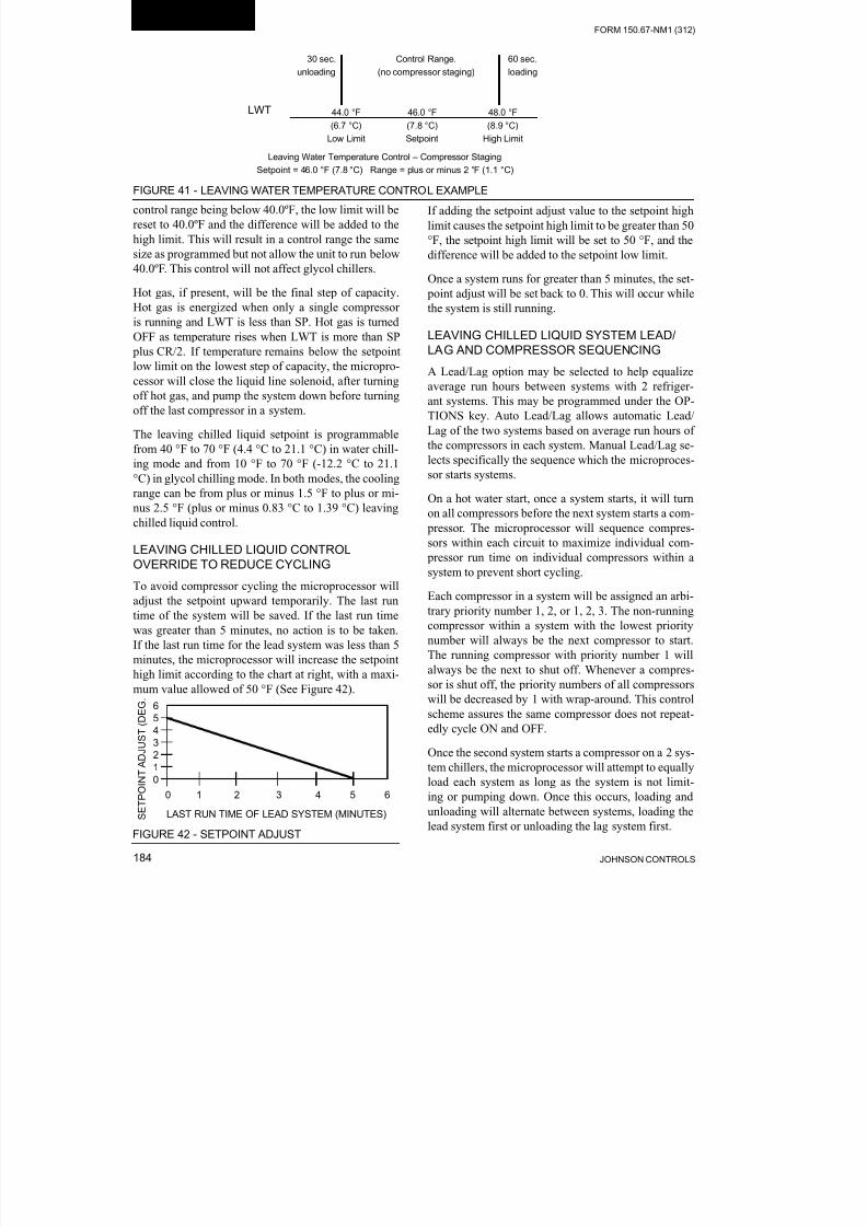
8/19/2019 Manual York
http://slidepdf.com/reader/full/manual-york 184/230JOHNSON CONTROLS184
FORM 150.67-NM1 (312)
Unit Operation
control range being below 40.0ºF, the low limit will be
reset to 40.0ºF and the difference will be added to the
high limit. This will result in a control range the same
size as programmed but not allow the unit to run below
40.0ºF. This control will not affect glycol chillers.
Hot gas, if present, will be the final step of capacity.
Hot gas is energized when only a single compressor
is running and LWT is less than SP. Hot gas is turned
OFF as temperature rises when LWT is more than SP plus CR/2. If temperature remains below the setpoint
low limit on the lowest step of capacity, the micropro-
cessor will close the liquid line solenoid, after turning
off hot gas, and pump the system down before turning
off the last compressor in a system.
The leaving chilled liquid setpoint is programmable
from 40 °F to 70 °F (4.4 °C to 21.1 °C) in water chill-
ing mode and from 10 °F to 70 °F (-12.2 °C to 21.1
°C) in glycol chilling mode. In both modes, the cooling
range can be from plus or minus 1.5 °F to plus or mi-
nus 2.5 °F (plus or minus 0.83 °C to 1.39 °C) leavingchilled liquid control.
LEAVING CHILLED LIQUID CONTROL
OVERRIDE TO REDUCE CYCLING
To avoid compressor cycling the microprocessor will
adjust the setpoint upward temporarily. The last run
time of the system will be saved. If the last run time
was greater than 5 minutes, no action is to be taken.
If the last run time for the lead system was less than 5
minutes, the microprocessor will increase the setpoint
high limit according to the chart at right, with a maxi-
mum value allowed of 50 °F (See Figure 42).
If adding the setpoint adjust value to the setpoint high
limit causes the setpoint high limit to be greater than 50
°F, the setpoint high limit will be set to 50 °F, and the
difference will be added to the setpoint low limit.
Once a system runs for greater than 5 minutes, the set-
point adjust will be set back to 0. This will occur while
the system is still running.
LEAVING CHILLED LIQUID SYSTEM LEAD/LAG AND COMPRESSOR SEQUENCING
A Lead/Lag option may be selected to help equalize
average run hours between systems with 2 refriger-
ant systems. This may be programmed under the OP-
TIONS key. Auto Lead/Lag allows automatic Lead/
Lag of the two systems based on average run hours of
the compressors in each system. Manual Lead/Lag se-
lects specifically the sequence which the microproces-
sor starts systems.
On a hot water start, once a system starts, it will turn
on all compressors before the next system starts a com- pressor. The microprocessor will sequence compres-
sors within each circuit to maximize individual com-
pressor run time on individual compressors within a
system to prevent short cycling.
Each compressor in a system will be assigned an arbi-
trary priority number 1, 2, or 1, 2, 3. The non-running
compressor within a system with the lowest priority
number will always be the next compressor to start.
The running compressor with priority number 1 will
always be the next to shut off. Whenever a compres-
sor is shut off, the priority numbers of all compressorswill be decreased by 1 with wrap-around. This control
scheme assures the same compressor does not repeat-
edly cycle ON and OFF.
Once the second system starts a compressor on a 2 sys-
tem chillers, the microprocessor will attempt to equally
load each system as long as the system is not limit-
ing or pumping down. Once this occurs, loading and
unloading will alternate between systems, loading the
lead system first or unloading the lag system first.
FIGURE 41 - LEAVING WATER TEMPERATURE CONTROL EXAMPLE
Leaving Water Temperature Control – Compressor Staging
Setpoint = 46.0 °F (7.8 °C) Range = plus or minus 2 °F (1.1 °C)
LWT
60 sec.
loading
30 sec.
unloading
Control Range.
(no compressor staging)
44.0 °F
(6.7 °C)
Low Limit
46.0 °F
(7.8 °C)
Setpoint
48.0 °F
(8.9 °C)
High Limit
0 1 2 3 4 5 6
LAST RUN TIME OF LEAD SYSTEM (MINUTES) S E T P O I N T A D J U S T ( D E G .
6
5
4
3
2
1
0
FIGURE 42 - SETPOINT ADJUST

8/19/2019 Manual York
http://slidepdf.com/reader/full/manual-york 185/230
FORM 150.67-NM1 (312)
185JOHNSON CONTROLS
RETURN CHILLED LIQUID CONTROL
(Can be used on Dual System 4, 5 and 6 compres-
sor Units Only)
Return chilled liquid control is based on staging the
compressors to match the cooling load. The chiller
will be fully loaded when the return water temperature
is equal to the Cooling Setpoint plus the Range. The
chiller will be totally unloaded (all compressors OFF)
when the return water temperature is equal to the Cool-
ing Setpoint (See sample in Table 17). At return water
temperatures between the Cooling Setpoint and Cool-
ing Setpoint plus Range, compressor loading and un-
loading will be determined by the formulas in Table 18.
Return Chilled Liquid Control MUST
only be used when constant chilled
liquid ow is ensured.
The range MUST always be pro-
grammed to equal the temperature
drop across the evaporator when the
chiller is “fully loaded”. Otherwise,
chilled liquid temperature will over or
under shoot. Variable ow must never
be used in return chilled liquid mode.
Normal loading will occur at intervals of 60 seconds
according to the temperatures determined by the for-
mulas. Unloading will occur at a rate of 30 seconds ac-
cording to the temperatures determined in the formulas
used to calculate the on and off points for each step ofcapacity.
The return chilled liquid setpoint is programmable
from 40 °F to 70 °F (4.4 °C to 21.1 °C) in water chill-
ing mode and from 10 °F to 70 °F (-12.2 °C to 21.1
°C) in glycol chilling mode. In both modes, the cooling
range can be from 4 °F to 20 °F (2.2° to 11.1 °C).
As an example of compressor staging (refer to Table 17),
a chiller with six compressors using a Cooling Setpoint
programmed for 45 °F (7.20 °C) and a Range Setpoint
of 10 °F (5.56 °C). Using the formulas in Table 18, the
control range will be split up into six (seven including
hot gas) segments, with the Control Range determin-
ing the separation between segments. Note also that the
Cooling Setpoint is the point at which all compressors
are OFF, and Cooling Setpoint plus Range is the point
all compressors are ON. Specifically, if the return wa-
ter temperature is 55 °F (12.8 °C), then all compressors
will be ON, providing full capacity. At nominal gpmthis would provide approximately 45 °F (7.2 °C) leaving
water temperature out of the evaporator.
If the return water temperature drops to 53.4 °F (11.9
°C), one compressor would cycle OFF leaving five
compressors running. The compressors would contin-
ue to cycle OFF approximately every 1.7 °F (.94 °C)
with the exception of hot gas bypass. Notice that the
hot gas bypass would cycle ON when the return water
temperature dropped to 46.25 °F (7.9 °C). At this point
one compressor would be running with hot gas.
Should the return water temperature rise from this
point to 46.7 °F (8.2 °C), the hot gas bypass would
shut OFF, still leaving one compressor running. As the
load increased, the compressors would stage on every
1.7 °F (.94 °C).
Also note that Table 18 not only provides the formu-
las for the loading (ON POINT) and unloading (OFF
POINT) of the system, the “STEP” is also shown in the
tables. The “STEP” is the increment in the sequence of
the capacity control scheme that can be viewed under
the OPER DATA key. Please refer to the section on the
DISPLAY/PRINT keys for specific information on the
OPER DATA key.
RETURN CHILLLED LIQUID SYSTEM LEAD/
LAG AND COMPRESSOR SEQUENCING
A lead/Lag option may be selected to help equalize
average run hours between systems with 2 refriger-
ant systems. This may be programmed under the OP-
TIONS key. Auto Lead/Lag of the 2 systems based on
average run hours of the compressors in each system
Manual Lead/Lag selects specifically the sequence
which the microprocessor starts the systems.
*Unloading only
TABLE 17 - SAMPLE COMPRESSOR STAGING FOR RETURN WATER CONTROL
COMPRESSOR STAGING FOR RETURN WATER CONTROL
4 COMPRESSOR
COOLING SETPOINT = 45 °F (7.2 °C) RANGE = 10 °F(5.6 °C)
# OF COMP ON 0 * 1+HG 1 2 3 4
RWT45 °F
(7.2 °C)
46.25 °F
(7.9 °C)
47.5 °F
(8.6 °C)
50.0 °F
(10.0 °C)
52.5 °F
(11.4 °C)
55.0 °F
(12.8 °C)

8/19/2019 Manual York
http://slidepdf.com/reader/full/manual-york 186/230JOHNSON CONTROLS186
FORM 150.67-NM1 (312)
Unit Operation
The microprocessor will sequence compressors load
and unload systems according to Table 19. The micro-
processor will lead/lag compressors within each circuit
to maximize individual compressor run time for the purpose of lubrication. It will also prevent the same
compressor from starting 2 times in a row. The micro-
processor will not attempt to equalize run time on indi-
vidual compressors within a system.
Each compressor in a system will be assigned an ar-
bitrary number 1, or 2. The non-running compressor
within a system with the lowest priority number will
always be the next compressor to start. The running
compressor with priority number 1 will always be the
next compressor to shut off. Whenever a compressor
is shut off, the priority numbers of all compressorsin each system will be decreased by 1 with the wrap
around. This control scheme assures the same com-
pressor does not repeatedly cycle ON and OFF.
ANTI-RECYCLE TIMER
The programmable anti-recycle timer assures that sys-
tems do not cycle. This timer is programmable under
the PROGRAM key between 300 and 600 seconds.
Whenever possible, to reduce cycling and motor heat-
ing, the anti-recycle timer should be adjusted to 600
seconds. The programmable anti-recycle timer starts
the timer when the first compressor in a system starts.
The timer begins to count down. If all of the compres-
sors in a circuit cycle OFF, a compressor within the cir-
cuit will not be permitted to start until the anti-recycle
timer has timed out. If the lead system has run for less
than 5 minutes, 3 times in a row, the anti-recycle timer
will be extended to 10 minutes.
ANTI-COINCIDENCE TIMER
This timer is not present on single-system units. Two
timing controls are present in software to assure com-
pressors within a circuit or between systems, do not
TABLE 18 - RETURN CHILLED LIQUID CONTROL FOR 4 COMPRESSORS (6 STEPS)
*STEP COMPRESSOR COMPRESSOR ON POINT COMPRESSOR OFF POINT
0 0 SETPOINT SETPOINT
1 1 W/HGB SP + CR/8 (NOTE 1) SETPOINT
2 1 NO HGB SP + CR/4 SP + CR/8
3 2 SP + 2*CR/4 (NOTE 2) SP + CR/4
4 2 SP + 2*CR/4 SP + CR/4 (NOTE 3)5 3 SP + 3*CR/4 SP + 2*CR/4
6 4 SP + CR SP + 3*CR/4
Notes:
1. Step 1 is Hot Gas Bypass and is skipped when loading occurs. Hot Gas Bypass operation is inhibited during pumpdown.
2. Step 3 is skipped when loading occurs.
3. Step 4 is skipped when unloading occurs.
* STEP can be viewed using the OPER DATA key and scrolling to COOLING DEMAND.
TABLE 19 - RETURN CHILLED LIQUID CONTROL FOR 4 COMPRESSORS (6 STEPS)
LEAD SYSTEM LAG SYSTEM
STEP COMP 1 COMP 2 - COMP 1 COMP 2 -
0 OFF OFF - OFF OFF -
1 ON + HG OFF - SEE NOTE 1 OFF OFF -
2 ON OFF - OFF OFF -
3 ON OFF - SEE NOTE 2 ON OFF -
4 ON ON - SEE NOTE 3 OFF OFF -
5 ON ON - ON OFF -
6 ON ON - ON ON -
NOTES
1. Step is Hot Gas Bypass and is skipped when loading occurs. Hot Gas Bypass operation is inhibited during pumpdown. For Leaving Chilled
Liquid Control the Hot Gas Bypass solenoid is energized only when the lead compressor is running and the LWT less than SP, the Hot Gas
Bypass solenoid is turned OFF when the LWT more than SP plus CR/2.
2. Step 3 is skipped when loading occurs.
3. Step 4 is skipped when unloading occurs.

8/19/2019 Manual York
http://slidepdf.com/reader/full/manual-york 187/230
FORM 150.67-NM1 (312)
187JOHNSON CONTROLS
start simultaneously. The anti-coincidence timer as-
sures there is at least a one minute delay between sys-
tem starts on 2-circuit systems. This timer is NOT pro-
grammable. The load timers further assure that there
is a minimum time between compressor starts within
a system.
EVAPORATOR PUMP CONTROL AND YORKHYDRO KIT PUMP CONTROL
The evaporator pump dry contacts (CTB2 – terminals
23 and 24) are energized when any of the following
conditions are true:
1. Low Leaving Chilled Liquid Fault.
2. Any compressor is running.
3. Daily Schedule is ON, Unit Switch is ON and Re-mote Stop is closed.
The pump will not run if the micro panel has been pow-
ered up for less than 30 seconds or if the pump has run inthe last 30 seconds to prevent pump motor overheating.
Whenever the option “YORK HYDRO KIT PUMPS =
1” is selected under the OPTIONS key, the pump con-
trol will be as described above. DO NOT SELECT the
option “YORK HYDRO KIT PUMPS = 2” under the
OPTIONS key. If a dual pump option is installed, the
active pump is selected by the selector switch.
EVAPORATOR HEATER CONTROL
The evaporator heater is controlled by ambient air tem-
perature. When the ambient temperature drops below
40 °F (4.4 °C) the heater is turned ON. When the tem-
perature rises above 45 °F (7.2 °C) the heater is turned
OFF. An under voltage condition will keep the heater
OFF until full voltage is restored to the system.
PUMPDOWN CONTROL
Each system has a pump-down feature upon shut-off.
Manual pumpdown from the keypad is not possible. On
a non-safety, non-unit switch shutdown, all compres-
sors but one in the system will be shut OFF. The LLSV
will also be turned OFF. The final compressor will beallowed to run until the suction pressure falls below the
cutout, or for 180 seconds, whichever comes first.
STANDARD CONDENSER FAN CONTROL
Condenser fan operation must be programmed with the
OPTIONS key under “Fan Control.” Condenser fan
control can be selected for Ambient Temperature and
Discharge Pressure, or Discharge Pressure only.
The condenser fan control by “Ambient Temperature
and Discharge Pressure” is a feature that is integral tothe standard software control. If the optional discharge
transducer is not installed, the condenser fans will op-
erate based on outdoor ambient temperature only. Re-
fer to the following pages for model specific details.
The condenser fan control by “Discharge Pressure” is
a feature that can be selected if the discharge pressure
transducer is installed and fan cycling is not a concern
Fan control by discharge pressure will work according
to the tables on the following pages. The fan contro
on-pressure and fan differential off-pressure are pro-
grammable under the PROGRAM key.
The delay between turning ON and OFF fan stages is
always fixed at 5 seconds.
When a fan stage is turned ON by pressure, the on
pressure for the next stage is increased 20 PSIG and
ramped back to the programmed on pressure over the
next 20 seconds. Typically, standard ambient contro
on pressure should be programmed at 385 PSIG with a
differential of 125 PSIG.
When a fan stage is turned OFF (programmed on pres-
sure minus programmed differential), the off pressurefor the next stage is decreased 20 PSIG and ramped
back to the programmed off pressure minus the differ
ential over the next 20 seconds.
A low ambient kit MUST be installed
when “AMBIENT CONTROL LOW
AMBIENT” is selected under the OP -
TIONS key.
Compressor damage could occur if programming does not match installed
hardware.
Detailed Standard Fan Control operation is shown in
Table 20 and 21.

8/19/2019 Manual York
http://slidepdf.com/reader/full/manual-york 188/230JOHNSON CONTROLS188
FORM 150.67-NM1 (312)
Unit Operation
LD12211
STANDARD CONDENSER FAN CONTROL – YCAL0019 – YCAL0033
TABLE 20 - YCAL0019 – YCAL0033 CONDENSER FAN CONTROL USING DISCHARGE PRESSURE
FAN
STAGEON* OFF*
CONTACTORMICROBOARD
OUTPUTFAN #
SYS 1 SYS 1 SYS 1
1DP> FAN CRTL ON
PRESS
DP < FAN CTRL ON
PRESS – DIFF.PRESS7M TB7-9 1
2
*DP > FAN CTRL
ON PRESS AND
FAN STAGE 1 IS
ENERGIZED
**DP < FAN CTRL ON
PRESS –
DIFF. PRESS
7M
&
8M
TB7-9
&
TB7-10
1
&
3
TABLE 21 - YCAL0019 – YCAL0033 CONDENSER FAN CONTROL USING DISCHARGE PRESSURE ONLY
FAN
STAGE ON OFF
CONTACTORMICROBOARD
OUTPUTFAN #
SYS 1 SYS 1 SYS 1
1
DP > FAN CTRL
ON PRESS
DP < FAN CTRL
ON PRESS – (DIFF.PRESS.)
7M TB7-9 1
2
DP > FAN CTRL
ON PRESS AND
FAN STAGE 1 IS
ENERGIZED
**DP < FAN CTRL ON
PRESS – DIFF. PRESS.
7M
&
8M
TB7-9
&
TB7-10
1
&
3
* When a fan stage is turned ON, the on pressure for the next stage is increased 20 PSIG and ramped back to the programmed
on pressure over the next 20 seconds.
** When a fan stage is turned OFF (programmed on pressure minus differential), the off pressure for the next stage is decreased
20 PSIG and ramped back to the programmed off pressure minus the differential.
FAN #1
FAN #2
FIGURE 43 - YCAL0019 – YCAL0033 FAN LOCATION (TYPICAL)

8/19/2019 Manual York
http://slidepdf.com/reader/full/manual-york 189/230
FORM 150.67-NM1 (312)
189JOHNSON CONTROLS
STANDARD CONDENSER FAN CONTROL – YCAL0043 – YCAL0066
TABLE 22 - YCAL0043 – YCAL0066 CONDENSER FAN CONTROL USING DISCHARGE PRESSURE.
FAN
STAGEON* OFF*
CONTACTORMICRO BOARD
OUTPUTFAN #
SYS 1 SYS 2 SYS 1 SYS 2 SYS 1 SYS 2
1DP> FAN CRTL ON
PRESS
DP < FAN CTRL ON
PRESS – DIFF.PRESS 7M 10M TB7-9 TB10-9 1 2
2
DP > FAN CTRL
ON PRESS AND
FAN STAGE 1 IS
ENERGIZED
DP < FAN CTRL ON
PRESS – DIFF. PRESS
7M
&
8M
10M
&
11M
TB7-9
&
TB7-10
TB10-9
&
TB10-10
1
&
3
2
&
4
TABLE 23 - YCAL0043 – YCAL0066 CONDENSER FAN CONTROL USING DISCHARGE PRESSURE ONLY
FAN
STAGEON OFF
CONTACTORMICRO BOARD
OUTPUTFAN #
SYS 1 SYS 2 SYS 1 SYS 2 SYS 1 SYS 2
1 DP > FAN CTRLON PRESS
DP < FAN CTRL ONPRESS – DIFF. PRESS.
7M 10M TB7-9 TB10-9 1 2
2
DP > FAN CTRL
ON PRESS AND
FAN STAGE 1 IS
ENERGIZED
DP < FAN CTRL ON
PRESS – DIFF. PRESS.
7M
&
8M
10M
&
11M
TB7-9
&
TB7-10
TB10-9
&
TB10-10
1
&
3
2
&
4
* When a fan stage is turned ON, the on pressure for the next stage is increased 20 PSIG and ramped back to the programmed
on pressure over the next 20 seconds.
** When a fan stage is turned OFF (programmed on pressure minus differential), the off pressure for the next stage is decreased
20 PSIG and ramped back to the programmed off pressure minus the differential.
FIGURE 44 - CAL0043 – YCAL0066 FAN LOCATION (TYPICAL)
LD11419
FAN #1
FAN #2
FAN #3
FAN #4
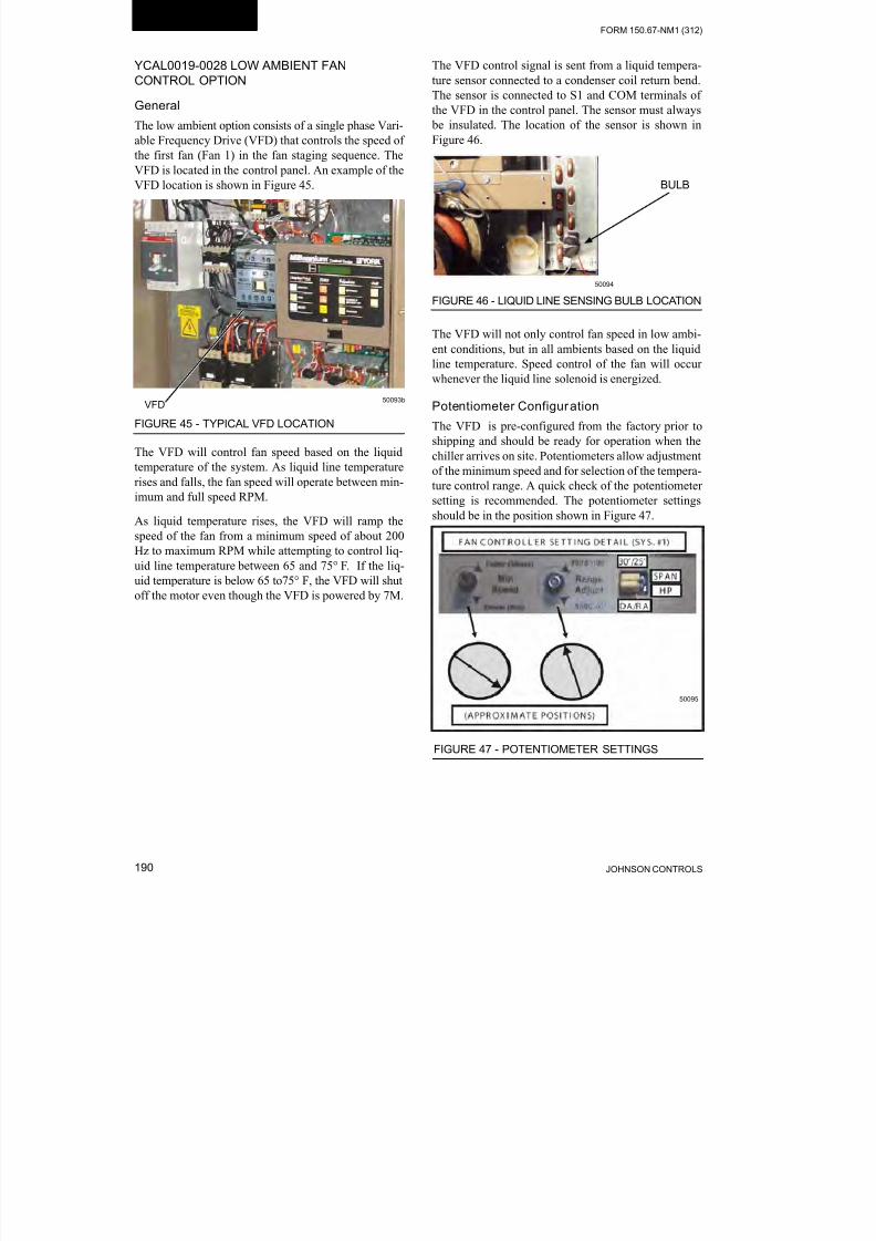
8/19/2019 Manual York
http://slidepdf.com/reader/full/manual-york 190/230JOHNSON CONTROLS190
FORM 150.67-NM1 (312)
Unit Operation
YCAL0019-0028 LOW AMBIENT FAN
CONTROL OPTION
General
The low ambient option consists of a single phase Vari-
able Frequency Drive (VFD) that controls the speed of
the first fan (Fan 1) in the fan staging sequence. The
VFD is located in the control panel. An example of theVFD location is shown in Figure 45.
FIGURE 45 - TYPICAL VFD LOCATION
50093bVFD
The VFD will control fan speed based on the liquid
temperature of the system. As liquid line temperature
rises and falls, the fan speed will operate between min-
imum and full speed RPM.
As liquid temperature rises, the VFD will ramp thespeed of the fan from a minimum speed of about 200
Hz to maximum RPM while attempting to control liq-
uid line temperature between 65 and 75° F. If the liq-
uid temperature is below 65 to75° F, the VFD will shut
off the motor even though the VFD is powered by 7M.
The VFD control signal is sent from a liquid tempera-
ture sensor connected to a condenser coil return bend.
The sensor is connected to S1 and COM terminals of
the VFD in the control panel. The sensor must always
be insulated. The location of the sensor is shown in
Figure 46.
BULB
FIGURE 46 - LIQUID LINE SENSING BULB LOCATION
50094
The VFD will not only control fan speed in low ambi-
ent conditions, but in all ambients based on the liquid
line temperature. Speed control of the fan will occur
whenever the liquid line solenoid is energized.
Potentiometer Configuration
The VFD is pre-configured from the factory prior to
shipping and should be ready for operation when the
chiller arrives on site. Potentiometers allow adjustment
of the minimum speed and for selection of the tempera-
ture control range. A quick check of the potentiometer
setting is recommended. The potentiometer settings
should be in the position shown in Figure 47.
FIGURE 47 - POTENTIOMETER SETTINGS
50095

8/19/2019 Manual York
http://slidepdf.com/reader/full/manual-york 191/230
FORM 150.67-NM1 (312)
191JOHNSON CONTROLS
Wiring
VFD wiring is simple and requires only single phase
power in, single phase power out and a 2-wire signal
from the liquid line temperature sensor. No start, stop
or other alternate power requirements are needed to op-
erate the VFD. Figure 48 shows the power and control
wiring schematically as well as the actual connections.
FIGURE 48 - WIRING
LD11799A

8/19/2019 Manual York
http://slidepdf.com/reader/full/manual-york 192/230JOHNSON CONTROLS192
FORM 150.67-NM1 (312)
Unit Operation
PROGRAMMING - YCAL0019 – 0028
Condenser fan control type must be programmed un-
der both the OPTIONS and PROGRAM keys when a
VFD is installed on the chiller. Under the OPTIONS
key, FAN CONTROL must be programmed for DIS-
CHARGE PRESSURE CONTROL only. This will as-
sure condenser fan control of the chiller is solely by
discharge pressure, with no ambient control.
Under the PROGRAM key, the FAN
CONTROL ON PRESSURE should
be programmed for 385 PSIG and the
FAN DIFFERENTIAL OFF PRES -
SURE must be programmed for 125
PSIG.
Programming as suggested assures the chiller control
points for the second fan in the fan staging sequence
and the inverter control points are matched for opti-
mum control of the fans at reduced ambient tempera-
tures, assuring superheat and oil control is not compro-
mised. When the chiller and VFD fan control points
are programmed properly, the fans will operate as out-
lined in Table 24.
YCAL0033 Low Ambient Fan Control Option
General
The low ambient option consists of a VFD (Variable
Frequency Drive) that controls the speed of the rst fan
(Fan 1) in the fan staging sequence. The VFD is locat-ed on the top of chiller above the compressor section.
Examples of the typical VFD location and enclosure
mountings are shown in Figures 49 and 50.
FIGURE 49 - TYPICAL VFD ENCLOSURE LOCATIONS
VFD Enclosure LocationLD12080
TABLE 24 - YCAL0019 – 0028 VFD LOW AMBIENT OPTION – CONDENSER FAN CONTROL OPERATION
FAN STAGE ON OFFCONTACTOR MICROBOARD FAN #
SYS 1 SYS 1 SYS 1
1:
VFD CONTROL
(1 FAN
VARIABLE
SPEED)
FAN SPEED
IS A FUNCTION OF
LIQUID TEMPERATURE
FAN WILL TURN ON
WHEN LIQUID LINE
TEMPERATURE IS
ABOVE 65º F. SPEED
INCREASES WITH
TEMPERATURE,
FAN WILL TURN OFF
WHEN LIQUIDTEMPERATURE DROPS
BELOW 65 °F
7M TB7-3 1
2:
1 FAN VFD
CONTROL
2ND FAN
FULL SPEEDUNDER
CONTACTOR
CONTROL
385 PSIG,
BOTH FANS
WILL BE RUNNINGFULL SPEED
DISCHARGE
PRESSURE
< 260 PSIG (PRESSURE
IS
< FAN CONTROL ON
PRESSURE OF
385 PSIG MINUS FANDIFFERENTIAL
PRESSURE OF 125 PSIG
= 260 PSIG)
FAN 1 WILL STILL
BE RUNNING
7M & 8M
TB7- 3
&
TB7-10
1 & 3

8/19/2019 Manual York
http://slidepdf.com/reader/full/manual-york 193/230

8/19/2019 Manual York
http://slidepdf.com/reader/full/manual-york 194/230

8/19/2019 Manual York
http://slidepdf.com/reader/full/manual-york 195/230
FORM 150.67-NM1 (312)
195JOHNSON CONTROLS
TB3
TB1 TB2
TO PANEL 7M TO FAN #1 (EXISTING HARNESS)TO MICROBOARD (P4)
151150 152150A151A152AWHT BLK
TB3
TB1 TB2TB3 TB1 TB2
TO PANEL 7M TO FAN #1 (EXISTING HARNESS)TO MICROBOARD (P4)
151150 152150A151A152AWHT BLK
LD11302a
FIGURE 53 - INVERTER WIRING
YCAL0033 PROGRAMMING
Condenser fan control type must be programmed un-
der both the OPTIONS and PROGRAM keys when an
VFD is installed on the chiller. Under the OPTIONSkey, FAN CONTROL must be programmed for DIS-
CHARGE PRESSURE CONTROL only. This will as-
sure the condenser fan control is solely by discharge
pressure with no ambient control.
Under the PROGRAM key, the FAN CONTROL ON
PRESSURE should be programmed for 425 PSIG and
the FAN DIFFERENTIAL OFF PRESSURE should be
programmed for 125 PSIG.
TABLE 26 - YCAL033 VFD LOW AMBIENT OPTION – CONDENSER FAN CONTROL OPERATION
FAN STAGE ON OFFCONTACTOR
MICRO
BOARDFAN #
SYS 1 SYS 1 SYS 1
1:
VFD CONTROL
(1 FAN
VARIABLE
SPEED)
FAN SPEED
IS A FUNCTION OF
DISCHARGE
PRESSURE.
WHEN THE LIQUID
LINE SOLENOID IS
ENERGIZED. SPEED
INCREASES WITH
PRESSURE
FAN WILL TURN
OFF OR TURN VERY
SLOWLY WHEN
PRESSURE DROPS
BELOW 260 PSIG.
7M TB7-3 1
2:
1 FAN VFD
CONTROL
2ND FAN
FULL SPEED
UNDER
CONTACTOR
CONTROL
425 PSIG,
BOTH FANS
WILL BE RUNNING
FULL SPEED
DISCHARGE
PRESSURE
< 260 PSIG
(PRESSURE IS
< FAN CONTROL ON
PRESSURE OF
425 PSIG MINUS FAN
DIFFERENTIAL
PRESSURE OF 125
PSIG = 300 PSIG)
7M
&
8M
TB7-3
&
TB7-10
3
Programming as suggested assures the chiller contro
points for the second fan in the fan staging sequence
and the inverter control points are matched for opti-mum control of the fans at reduced ambient tempera-
tures, assuring superheat and oil control is not compro-
mised. When the chiller and VFD fan control points are
programmed properly, the fans will operate as outlined
in Table 26.

8/19/2019 Manual York
http://slidepdf.com/reader/full/manual-york 196/230JOHNSON CONTROLS196
FORM 150.67-NM1 (312)
Unit Operation
YCAL0043 – 0066 LOW AMBIENT FAN
CONTROL OPTION
General
The low ambient option consists of a VFD (Variable
Frequency Drive) for each system that controls the
speed of the rst fan (Fan 1, Sys #1 or Fan 2, Sys # 2)
in the fan staging sequence. The VFD’s are located inan enclosure in the compressor/piping/heat exchanger
section on (2) compressor chillers. System # 1 VFD
is located on the bottom and System # 2 is on the top.
Single system chillers have the VFD installed on the
top of chiller above the compressor section. Examples
of the typical VFD location and enclosure mountings
are shown in Figures 54 and 55.
The VFD will control fan speed when only a single
fan is running on a system. As discharge pressure ris-
es, the fan speed will be increased from zero RPM to
full speed. As discharge pressure continues to rise, theVFD will operate the fan at full speed and the second
fan will be brought ON in a system, if needed. When-
ever the second fan is brought ON, the inverter will
already be running the first fan at full speed.
If discharge pressure falls, the chiller microprocessor
will turn the second fan OFF by de-energizing the fan
contactor. If pressure continues to fall, VFD speed will
decrease in an effort to maintain discharge pressure.
Speed may drop to the point where the VFD turns the
fan completely OFF or virtually OFF with a continued
drop in pressure.
Single System VFD Enclosure Location
LD12080
The VFD control input signal is from the discharge
pressure transducer in the respective system. The
transducer signal feeds both the chiller microprocessor
board input and the VFD.
The VFD will control the fan speed not only in low
ambient conditions, but in all ambients based on dis-
charge pressure. Speed control of the respective sys-
tem will occur whenever high voltage power is applied
to the VFD power inputs through the 7M (Sys 1) or
10M (Sys 2) contactors. The chiller microprocessor
will energize the 7M and 10M contactors whenever
the respective system liquid line solenoid is energized.
The VFD controls the speed of the fan based on a
discharge pressure setpoint and a differential control
range. When a compressor starts in a system, the in-
verter is activated through the 7M (Sys 1) or 10 M (Sys
2) contactor, which is controlled from the respective
liquid line solenoid valve control signal. At discharge
pressures below 260 PSIG, the VFD will turn the fan
OFF or speed will be reduced to small movements in
fan rotation.
The pressures indicated in this section
describing the VFD control will vary
from VFD to VFD. Expect tolerances
for the entire pressure range of con-
trol to potentially shift -0 PSIG/+24
PSIG.
The VFD will ramp up the speed of the fan as pres-sure rises above the low end of the speed control range.
Throughout the pressure control range, the VFD con-
trols the speed of the fan based on discharge pressure
in the range of approximately 260 to 292 PSIG. At
pressures above 260 PSIG, the VFD will run the sys-
tem fan at full speed.
FIGURE 54 - TYPICAL VFD ENCLOSURE LOCATIONS
Dual System VFD Enclosure Location
LD11298

8/19/2019 Manual York
http://slidepdf.com/reader/full/manual-york 197/230
FORM 150.67-NM1 (312)
197JOHNSON CONTROLS
As pressure drops below 292 PSIG, the VFD will slow
the speed of the fan to try to maintain discharge pres-
sure within the control range. The VFD will try to
maintain pressure in the range of 260 to 292 PSIG by
raising and lowering the speed of the fan. If pressure
drops below 260 PSIG, the VFD will virtually turn the
system fan completely OFF. Some slight fan move-
ment or very slow rotation may be noted, although the
fan may appear to stop completely.
CONFIGURATION (JUMPERS AND
POTENTIOMETERS)
Each VFD is pre-configured at the factory prior to
shipping and should be ready for operation when it ar-
rives onsite. A quick check of the settings is recom-
mended. The jumpers must be in the positions shown
in Table 27.
TABLE 27 - VFD JUMPERSJUMPER 60 HZ 50 HZ
J2 REMOVE — J3 IN — J4 REMOVE — J5 IN — J6 IN — J7 IN — J8 IN — J9 IN REMOVE
FIGURE 55 - TYPICAL VFD ENCLOSURE CONFIGURATIONS
Dual System VFD Enclosure
S Y S. # 2
S Y S. # 1
Single System VFD Enclosure
LD1208
LD11299a
Potentiometer settings are also preset at the factory
The potentiometers should be in the positions shown in
Figure 57. The pots do not have numerical settings and
are set according to the arrow positions indicated. DO
NOT change the potentiometer settings unless they do
not match the positioning of the potentiometers shownin Figure 57. The position of the potentiometers are as
follows:
• P1 should be full CW (260 PSIG)
• P2 should be full CCW (32 PSIG).
Modifying these settings may cause damage to the
chiller or control problems.
The P1 pot sets the setpoint which is the top end of the
control range. This setting is the discharge pressure a
which the fan will be operating at full speed. The P2
pot sets the range. This is the range of pressure wherethe VSD modulates the fan speed from 0 RPM to ful
speed. The range is subtracted from the setpoint to cal
culate the 0 RPM pressure.
Wiring
VFD wiring is simple and requires only 3-phase power
in, 3-phase power out, and a 2-wire signal from the
transducer. No start, stop, or other alternate power re

8/19/2019 Manual York
http://slidepdf.com/reader/full/manual-york 198/230JOHNSON CONTROLS198
FORM 150.67-NM1 (312)
Unit Operation
quirements are needed to run the VFD. Figure’s 56 and
57 show the power and control wiring schematically
as well as the actual connections. The VFD controlled
fan will operate whenever the liquid line solenoid on
the respective system is energized.
PROGRAMMING
Condenser fan control type must be programmed un-der both the OPTIONS and PROGRAM keys when a
VFD is installed on the chiller. Under the OPTIONS
key, FAN CONTROL must be programmed for DIS-
CHARGE PRESSURE CONTROL only. This will as-
sure condenser fan control of the chiller is solely by
discharge pressure, with no ambient control.
Under the PROGRAM key, the FAN
CONTROL ON PRESSURE should
be programmed for 425 PSIG and the
FAN DIFFERENTIAL OFF PRES -
SURE must be programmed for 125
PSIG.
Programming as suggested assures the chiller control
points for the second fan in the fan staging sequence
and the inverter control points are matched for opti-
150A L1 T1 150
151A L2 T2 151
152A L3 T3 152
CONDENSER
FAN NO. 1
SPEED
CONTR.
7M
250A L1 T1 250
251A L2 T2 251
252A L3 T3 252
CONDENSER
FAN NO. 2
SPEED
CONTR.
10M
LD11301
FIGURE 56 - INVERTER POWER WIRING SC
mum control of the fans at reduced ambient tempera-
tures. When the chiller and VFD fan control points are
programmed properly, the fans will operate as outlined
in Table 28.
P1 P2P1 P2
POTENTIOMETER SETTINGS
P1 P2
292 PSI 32 PSI
FIGURE 57 - POTENTIOMETER SETTINGS
LD11300a

8/19/2019 Manual York
http://slidepdf.com/reader/full/manual-york 199/230
FORM 150.67-NM1 (312)
199JOHNSON CONTROLS
TB3
TB1 TB2
TO PANEL 10 M TO FAN #2 (EXISTING HARNESS)TO MICROBOARD (P7)
251250 252250A251A252AWHT BLK
TB3 TB1 TB2
TO PANEL 10 M TO FAN #2 (EXISTING HARNESS)TO MICROBOARD (P7)
251250 252250A251A252AWHT BLK
TB3
TB1TB2
TO PANEL 7M TO FAN #1 (EXIS TING HARNESS)TO MICROBOARD (P4)
151150 152150A151A152AWHT BLK
TB3
TB1TB2TB3 TB1TB2
TO PANEL 7M TO FAN #1 (EXIS TING HARNESS)TO MICROBOARD (P4)
151150 152150A151A152AWHT BLK
FIGURE 58 - INVERTER WIRING
LD11302
TABLE 28 - YCAL0043-0066 VFD LOW AMBIENT OPTION – CONDENSER FAN CONTROL OPERATION
FAN STAGE ON OFFCONTACTOR MICROBOARD FAN #
SYS 1 SYS 2 SYS 1 SYS 2 SYS 1 SYS 2
1:
VFD CONTROL
(1 FAN
VARIABLE
SPEED)
FAN SPEED
IS A FUNCTION
OFDISCHARGE
PRESSURE.
WHEN THE
LIQUID LINE
SOLENOID IS
ENERGIZED,
SPEED
INCREASES
WITH PRESSURE
FAN WILL
TURN OFF OR
TURN VERY
SLOWLY WHEN
PRESSURE
DROPS BELOW
260 PSIG.
7M 10M TB7-3 TB10-9 1 2
2:
1 FAN VFD
CONTROL
2ND FAN
FULL SPEED
UNDER
CONTACTOR
CONTROL
425 PSIG,
BOTH FANS
WILL BE
RUNNING FULL
SPEED
DISCHARGE
PRESSURE
< 260 PSIG
(PRESSURE IS
< FAN CONTROL
ON PRESSURE
OF
425 PSIG
MINUS FAN
DIFFERENTIAL
PRESSURE OF
125 PSIG = 300
PSIG)
7M
&
8M
10M
&
11M
TB7-3
AND
TB7-10
TB10-9
AND
TB10-
10
1
&
3
2
&
4

8/19/2019 Manual York
http://slidepdf.com/reader/full/manual-york 200/230JOHNSON CONTROLS200
FORM 150.67-NM1 (312)
Unit Operation
LOAD LIMITING
Load Limiting is a feature that prevents the unit from
loading beyond the desired value. Two and Four com-
pressor units can be load limited to 50%. This would
allow only 1 compressor per system to run. Three and
six compressor units can be load limited to 33% or
66%. The 66% limit would allow up to 2 compressors
per system to run, and the 33% limit would allow only
1 compressor per system to run. Five compressor units
may be load limited to 40% (1 compressor per system
runs) or 80% (up to 2 compressors per system) are per-
mitted to run. No other values of limiting are available.
There are two ways to load limit the unit. The first is
through remote communication via an ISN. Load limit
stages are sent through YORK Talk on pages 9 and 10
of feature 54. Page 9 is stage 1 load limit and page 10
is stage 2 load limit.
A second method of load limiting the unit is throughclosing dry contacts connected to the Load Limit
(CTB1 – Terminals 13 to 21). Load limiting involves
closing the Load Limit input with a dry contact. Load
limiting is either 80%, 66% or 50%, depending on the
number of compressors on the unit. Table 29 shows
the load limiting permitted for the various number of
compressors. Only Stage 1 is available utilizing a dry
contact.
Simultaneous operation of Remote
Load Limiting and EMS-PWM Tem-
perature Reset (described on following
pages) cannot occur.
TABLE 29 - COMPRESSOR OPERATION –LOAD
LIMITING
COMPRESSORS
IN UNIT
STAGE 1 STAGE 2
2 50% -
3 66% 33%
4 50% -
5 80% 40%
6 66% 33%
COMPRESSOR RUN STATUS
Compressor run status is indicated by closure of con-
tacts at CTB2 – terminals 25 to 26 for system 1 and
CTB2 – terminals 27 to 28 for system 2.
ALARM STATUS
System or unit shutdown is indicated by normally open
alarm contacts opening whenever the unit shuts down
on a unit fault, locks out on a system fault, or experi-
ences a loss of power to the chiller electronics . System
1 alarm contacts are located at CTB2 – terminals 29
to 30. System 2 alarm contacts are located at CTB2 –
terminals 31 to 32. The alarm contacts will close when
conditions allow the unit to operate, or the fault is reset
during a loss of power, the contacts will remain open
until power is reapplied and no fault conditions exist.
BAS/EMS TEMPERATURE RESET USING
A VOLTAGE OR CURRENT SIGNAL
The Remote Reset Option allows the Control Center
of the unit to reset the chilled liquid setpoint using a
0 to 10VDC input, or a 4 to 20mA input connected to
CTB1 terminals A- and A+. Whenever a reset is called
for, the change may be noted by pressing the CoolingSetpoints key twice. The new value will be displayed
as “REM SETP = XXX °F.”
If a 0 to 10VDC signal is supplied, it is applied to ter-
minals A+ and A-, and jumper JP1 on the I/O board
must be inserted between pins 2 and 3. To calculate the
reset chilled liquid setpoint for values between 0VDC
and 10VDC use the following formula:
Setpoint = Local Chilled Liquid Setpoint + °Reset
°Reset = (DC voltage signal) x (*Max Reset Value)
10
Example:
Local Chilled Liquid Setpoint = 45 °F (7.22 °C)
*Max Reset Value = 20 °F (11.11 °C)
Input Signal = 6VDC
(English)
°Reset = 6VDC x 20 °F = 12 °F Reset
10
New Setpoint = 45 °F + 12 °F = 57 °F
(Metric)
°Reset = 6VDC x 11. 11 °C = 6.67 °C Reset
10
New Setpoint = 7.22 °C + 6.67 °C = 13.89 °C
* M a x R e s e t V a l u e i s t h e “ M a x E M S - P W M R e -
mote Temperature Reset” setpoint value descr ibed
in the programming sect ion under Cooling Setpoints.
Programmable values are from 2 °F to 40 °F (1.11 °C to 11.11 °C).

8/19/2019 Manual York
http://slidepdf.com/reader/full/manual-york 201/230
FORM 150.67-NM1 (312)
201JOHNSON CONTROLS
If a 4-20mA signal is supplied, it is applied to termi-
nals A+ and A- and jumper JP1 on the I/O board
must be installed between pin 1 and 2. To calculate
the chilled liquid setpoint for values between 4mA and
20 mA use the following formula:
Setpoint = Local Chilled Liquid Setpoint + °Reset
°Reset = (mA signal - 4) x (*Max Reset Value)
16
Example:
Local Chilled Liquid Setpoint = 45° (7.22 °C)
*Max Reset Value = 10 °F (5.56 °C)
Input Signal = 12 mA
(English)
°Reset = 8mA x 10 °F = 5 °F Reset
16
Setpoint = 45 °F + 5 °F = 50 °F
(Metric)
°Reset = 8mA x 5.56 °C = 2.78 °C Reset
16Setpoint = 7.22 °C + 2.78 °C = 10.0 °C
A 240-24 Volt Ratio Transformer (T3)
is used to derive nominal 12 volt out -
put from the 120 volt supply.

8/19/2019 Manual York
http://slidepdf.com/reader/full/manual-york 202/230JOHNSON CONTROLS202
FORM 150.67-NM1 (312)
THIS PAGE INTENTIONALLY LEFT BLANK

8/19/2019 Manual York
http://slidepdf.com/reader/full/manual-york 203/230
FORM 150.67-NM1 (312)
203JOHNSON CONTROLS
SYS 1 HGBP STATUS TB7-7 IS:
SYS 2 COMP 1 STATUS TB10-2 IS:
SYS 2 LLSV STATUS TB10-3 IS:
SYS 2 COMP 2 STATUS TB10-4 IS:
SYS 2 COMP 3 STATUS TB10-5 IS:
SYS 1 FAN OUTPUT 1 TB7-8 IS:
SYS 1 FAN OUTPUT 2 TB7-9 IS:
SYS 1 FAN OUTPUT 3 TB7-10 IS:
SYS 2 FAN OUTPUT 1 TB10-8 IS:
SYS 2 FAN OUTPUT 2 TB10-9 IS:
SYS 2 FAN OUTPUT 3 TB10-10 IS:
EVAP HEATER STATUS TB8-2 IS:
SYS 1 ALARM STATUS TB8-3 IS:
SYS 2 ALARM STATUS TB9-2 IS:
EVAP PUMP STATUS TB8-6,7 IS:
SYS 2 HGBV STATUS TB10-7 IS:
SPARE DO TB8-4 IS:
SPARE DO TB8-5 IS:SPARE DO TB8-8, 9 IS:
SPARE DO TB9-4 IS:
SYS 1 EEV OUTPUT TB5-1, 2 = XXX%
SYS 2 EEV OUTPUT TB6-1, 2 = XXX%
SYS 1 COND FAN SPEED J15-1,5 = XXX%
SYS 2 COND FAN SPEED J15-2,6 = XXX%
SPARE AO J15-3,7 = XXX%
SPARE AO J15-4,8 = XXX%
DATA LOGGING MODE 1 = ON, 0 = OFF
DATA LOGGING TIMER X SECS
SOFT START (disabled)
REFRIGERANT TYPE (R410A only)
EXPANSION VALVE TYPE (Thermostatic Only)
REMOTE TEMP RESET OPTION =
REMOTE INPUT SERVICE TIME =
“NORTH AMERICAN FEATURE SET ENABLED”
HYDRO PUMP SELECTION
EVAP PUMP TOTAL RUN HOURS
SYS 1 HOURS
SYS 2 HOURS
SYS 1 STARTS
SYS 2 STARTS
Each display will also show the output connection onthe microboard for the respective output status shown
For example:
S Y S 1 L L S V S T A T U S
T B 10 - 3 I S O F F
This display indicates that the system 1 liquid line sole-
noid valve is OFF, and the output connection from the
microboard is coming from terminal block 10 – pin 3.
SECTION 9 – SERVICE AND TROUBLESHOOTING
CLEARING HISTORY BUFFERS
The history buffers may be cleared by pressing the
HISTORY key and then repeatedly pressing the UP
arrow key until you scroll past the last history buffer
choice. The following message will be displayed:
I I N I T I A L I Z E H I S T O R Y
E N T E R = Y E S
Pressing the ENTER/ADV key at this display will
cause the history buffers to be cleared. Pressing any
other key will cancel the operation.
DO NOT CLEAR BUFFERS. Impor -
tant information may be lost. Contact
factory service.
SERVICE MODE
Service Mode is a mode that allows the user to enable
or disable all of the outputs (except compressors) on
the unit, change chiller configuration setup parameters
and view all the inputs to the microboard.
To enter Service Mode, turn the Unit Switch OFF and
press the following keys in the sequence shown; PRO-
GRAM, UP ARROW, UP ARROW, DOWN ARROW,
DOWN ARROW, ENTER. Service Mode will time outafter 30 minutes and return to normal control mode, if
the panel is accidentally left in this mode. Otherwise,
turning the Unit Switch ON will take the panel out of
Service Mode.
SERVICE MODE – OUTPUTS
After pressing the key sequence as described, the con-
trol will enter Service Mode permitting the outputs
(except compressors), operating hours, refrigerant
type, expansion valve type, and start/hour counters to
be viewed and or modified. The ENTER/ADV key is
used to advance through the outputs. Using the ↑ and ↓
(UP/DOWN ) arrow keys will turn the respective digi-
tal output ON/OFF or modify the value.
Following is the order of outputs that will appear as the
ENTER/ADV key is pressed:
SYS 1 COMP 1 STATUS TB7-2 IS:
SYS 1 LLSV STATUS TB7-3 IS:
SYS 1 COMP 2 STATUS TB7-4 IS:
SYS 1 COMP 3 STATUS TB7-5 IS:

8/19/2019 Manual York
http://slidepdf.com/reader/full/manual-york 204/230JOHNSON CONTROLS204
FORM 150.67-NM1 (312)
Service and Troubleshooting
Pressing the ↑ (UP) arrow key will energize the liquid
line solenoid valve and OFF will change to ON in the
display as the LLSV is energized. Energizing and de-en-
ergizing outputs may be useful during troubleshooting.
SERVICE MODE – CHILLER CONFIGURATION
After the Outputs are displayed, the next group of dis-
plays relate to chiller configuration and start/hour coun-ters. Data logging, soft start, refrigerant type, pump
control selection and expansion valve type all must be
programmed to match actual chiller configuration.
Soft start (disabled), Refrigerant Type
(R410A), and Expansion Valve Type
(Thermostatic), and North American
Feature (Enabled) MUST be properly
programmed or damage to compres-
sors and other system components
may result.Following is a list of chiller configuration selections, in
order of appearance:
DATA LOGGING MODE = : DO NOT MODIFYDATA LOGGING TIMER = : DO NOT MODIFY
SOFT START
REFRIGERANT TYPE
EXPANSION VALVE TYPE
REMOTE TEMP RESET OPTION
REMOTE INPUT SERVICE TIME
FEATURE SETPUMP CONTROL SELECTION
SYS 1 HOURS
SYS 2 HOURS
SYS 1 STARTS
SYS 2 STARTS
The last displays shown on the above list are for the ac-
cumulated run and start timers for each system. All val-
ues can also be changed using the ↑ (UP) and ↓ (Down)
arrow keys, but under normal circumstances would not
be required or advised. After the last start display, themicroprocessor will display the first programmable
value under the PROGRAM key.
SERVICE MODE – ANALOG AND DIGITAL
INPUTS
After entering Service Mode (press PROGRAM ↑↑
↓↓ ENTER), all digital and analog inputs to the mi-
croboard can be viewed by pressing the OPER DATA
key. After pressing the OPER DATA key, the ↑ (UP)
arrow and ↓ (DOWN) arrow keys are used to scroll
through the analog and digital inputs.
Following is the order of analog and digital inputs that
will appear when sequenced with the ↓ (Down) arrow
key:
(analog inputs)
SYS 1 SUCT PRESSURE
UNIT TYPE
SYS 1 *DISCH PRESSURE
SYS 1** SUCTION TEMP.
SYS 2** SUCTION TEMP.AMBIENT AIR TEMP.
LEAVING LIQUID TEMP.
RETURN LIQUID TEMP.
SYS 2 SUCTION PRESSURE
SYS 2 SPARE
SYS 2 *DISCH PRESSURE
SYS 1 MTR VOLTS
SYS 2 MTR VOLTS
(digital inputs)
PWM TEMP RESET INPUTLOAD LIMIT INPUTFLOW SW / REM START
SPARESINGLE SYSTEM SELECTSYS 1 MP / HPCO INPUTSYS 2 MP / HPCO INPUT
* The discharge pressure transducer is optional on some models.
** The suction temperature sensor is on EEV units only.
The analog inputs will display the input connection,
the temperature or pressure, and corresponding input
voltage such as:
S Y S 1 S U C T P R J 7 - 1 0
2 . 1 V D C = 8 1 P S I G

8/19/2019 Manual York
http://slidepdf.com/reader/full/manual-york 205/230
FORM 150.67-NM1 (312)
205JOHNSON CONTROLS
This example indicates that the system 1 suction pres-
sure input is connected to plug 7 – pin 10 (J7-10) on the
I/O board. It indicates that the voltage is 2.1VDC which
corresponds to 81 PSIG (5.6 bars) suction pressure.
The digital inputs will display the input connection and
ON/OFF status such as:
F L O W S W / R E M S T A R T
J 13 - 5 I S O N
This indicates that the flow switch/remote start input is
connected to plug 13- pin 5 (J13-5) on the microboard,
and is ON (ON = +30VDC unregulated input, OFF =
0VDC input on digital inputs).
CONTROL INPUTS/OUTPUTS
Tables 30 through 33 are a quick reference list provid-
ing the connection points and a description of the in-
puts and outputs respectively. All input and output con-nections pertain to the connections at the microboard.
TABLE 30 - I/O DIGITAL INPUTS
J13-2 Unit ON/OFF Switch
J13-3 Load Limit Stage 2 on 3, 5 & 6 Comp. Units
J13-4 Load Limit Stage 1
J13-5 Flow Switch and Remote Start/Stop
J13-6 Spare
J13-7Single System Select
(Jumper = Single Sys, No Jumper = Two Sys)
J13-8 CR1(Sys 1 Motor Protector/High Pressure Cutout)
J13-10CR2
(Sys 2 Motor Protector/High Pressure Cutout)
TABLE 31 - I/O DIGITAL OUTPUTS
TB7-2 SYS 1 Compressor 1
TB7-3 SYS 1 Liquid Line Solenoid Valve
TB7-4 SYS 1 Compressor 2
TB7-5 SYS 1 Compressor 3
TB7-7 SYS 1 Hot Gas Bypass Valve
TB10-2 SYS 2 Compressor 1
TABLE 31 - I/O DIGITAL OUTPUTS
TB10-3 SYS 2 Liquid Line Solenoid Valve
TB10-4 SYS 2 Compressor 2
TB10-5 SYS 2 Compressor 3
TB7-8 SYS 1 Condenser Fan Output 1
TB7-9 SYS 1 Condenser Fan Output 2
TB7-10 SYS 1 Condenser Fan Output 3TB10-8 SYS 2 Condenser Fan Output 1
TB10-9 SYS 2 Condenser Fan Output 2
TB10-10 SYS 2 Condenser Fan Output 3
TB8-2 Evaporator Heater
TB8-3 SYS 1 Alarm
TB9-2 SYS 2 Alarm
TB8-6 & 7 Evaporator Pump Starter
TB10-7 SYS 2 Hot Gas Bypass Valve
TABLE 32 - I/O ANALOG INPUTS
J7-10
SYS 1 Suction Transducer
-or-
SYS 1 Low Pressure Switch
J11-12
Unit Type: Chiller = NO Jumper J11-12 to +24
VDC
YCUL Condensing Unit = Jumper J11-12 to +24
VDC (Do NOT Use)
J7-11 SYS 1 Discharge Pressure Transducer (Optional)
J6-9 Ambient Air Temperature Sensor
J6-7 Leaving Chilled Liquid Temperature Sensor
J6-8 Return Chilled Liquid Temperature Sensor
J9-10
SYS 2 Suction Pressure Transducer
-or-
SYS 2 Low Pressure Switch
J9-11SYS 2 Discharge Pressure Transducer
(Optional)
J7-12 Unit/SYS 1 Voltage
J9-12 SYS 2 Voltage
J11-11 Remote Temperature Reset
TABLE 33 - I/O ANALOG OUTPUTS
N/A Not Applicable
(CONT’D)

8/19/2019 Manual York
http://slidepdf.com/reader/full/manual-york 206/230JOHNSON CONTROLS206
FORM 150.67-NM1 (312)
Service and Troubleshooting
FIGURE 59 - MICROBOARD LAYOUT
TB5
TB1
TB6
TB7
TB8
TB9
TB10
J14J13
J12
J15
J11
J10
J9
J8
J7
J6
J5
J3
I/O BOARD
IPU
BOARD
JP1
LD12721

8/19/2019 Manual York
http://slidepdf.com/reader/full/manual-york 207/230
FORM 150.67-NM1 (312)
207JOHNSON CONTROLS
CHECKING INPUTS AND OUTPUTS
Digital Inputs
Refer to the unit wiring diagram. All digital inputs are
connected to J13-1 of the I/O board. The term “digital”
refers to two states – either ON or OFF. As an example,
when the flow switch is closed, 30VDC will be applied
to J13, pin 5 (J13-5) of the I/O board. If the flow switchis open, 0VDC will then be present at J13-5.
Pin 1 of J13 is an unregulated 30VDC source used to
supply the DC voltage to the various user contacts, unit
switch, flow switch, etc. This DC source is factory wired
to CTB1, terminal 13. Any switch or contact used as a
digital input would be connected to this terminal, with
the other end connecting to its respective digital input on
the microboard. Any time a switch or contact is closed,
30VDC would be applied to that particular digital input.
Any time a switch or contact is open, 0VDC would be
applied to that particular digital input.
Typically, voltages of 24 to 36VDC could be measured
for the DC voltage on the digital inputs. This voltage is
in reference to ground. The unit case should be suffi-
cient as a reference point when measuring digital input
voltages.
Analog Inputs – Temperature
Refer to the unit wiring diagram. Temperature inputs
are connected to the microboard on plug J6. These ana-
log inputs represent varying DC signals corresponding
to varying temperatures. All voltages are in referenceto the unit case (ground). Following are the connec-
tions for the temperature sensing inputs:
Outside Air Sensor
J6-6 = +5VDC regulated supply to sensor.
J6-9 = VDC input signal to the microboard.
See Table 34 for voltage readings that correspond to
specific outdoor temperatures.
J6-3 = drain (shield connection = 0VDC) Return
TABLE 34 - OUTDOOR AIR SENSOR
TEMPERATURE/VOLTAGE /
CORRELATION
TEMP °F
VOLTAGE
(SIGNAL INPUT
TO RETURN)
TEMP °C
0 0.7 -18
5 0.8 -15
10 0.9 -12
15 1.0 -9
20 1.1 -7
25 1.2 -4
30 1.4 -1
35 1.5 2
40 1.7 4
45 1.8 7
50 2.0 10
55 2.2 1360 2.3 16
65 2.5 18
70 2.6 21
75 2.8 24
80 2.9 27
85 3.1 29
90 3.2 32
95 3.4 35
100 3.5 38
105 3.6 41
110 3.7 43
115 3.8 46
120 3.9 49
125 4.0 52
130 4.1 54

8/19/2019 Manual York
http://slidepdf.com/reader/full/manual-york 208/230JOHNSON CONTROLS208
FORM 150.67-NM1 (312)
Service and Troubleshooting
Liquid and Refrigerant Sensor Test Points
(Table 35)
Entering Chilled Liquid Sensor
J6-5 = +5VDC regulated supply to sensor.
J6-8 = VDC input signal to the I/O board. See Table 35
for voltage readings that correspond to specificliquid temperatures.
J6-2 = Drain (shield connection = 0VDC) Return.
Leaving Chilled Liquid Temperature Sensor
J6-4 = +5VDC regulated supply to sensor.
J6-7 = VDC input signal to the microboard. See Table
35 for voltage readings that correspond to spe-
cific liquid temperatures.
J6-1 =drain (shield connection = 0VDC) Return.
TABLE 35 - ENTERING/LEAVING CHILLED
LIQUID TEMPERATURE SENSOR
TEMP °F
VOLTAGE
(SIGNAL INPUT
TO RETURN)
TEMP °C
10 1.33 -12
12 1.39 -11
14 1.46 -10
16 1.51 -9
18 1.58 -8
20 1.65 -7
22 1.71 -6
24 1.78 -4
26 1.85 -3
28 1.91 -2
30 1.98 -1
32 2.05 0
34 2.12 136 2.19 2
38 2.26 3
40 2.33 4
42 2.40 6
44 2.47 7
46 2.53 8
48 2.60 9
50 2.65 10
52 2.73 11
54 2.80 12
56 2.86 13
58 2.92 14
60 2.98 16
62 3.05 17
64 3.11 18
66 3.17 19
68 3.23 20
70 3.29 21
72 3.34 22
74 3.39 23
76 3.45 2478 3.5 26
80 3.54 27
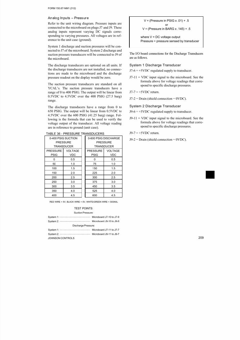
8/19/2019 Manual York
http://slidepdf.com/reader/full/manual-york 209/230
FORM 150.67-NM1 (312)
209JOHNSON CONTROLS
Analog Inputs – Pressure
Refer to the unit wiring diagram. Pressure inputs are
connected to the microboard on plugs J7 and J9. These
analog inputs represent varying DC signals corre-
sponding to varying pressures. All voltages are in ref-
erence to the unit case (ground).
System 1 discharge and suction pressures will be con-nected to J7 of the microboard. System 2 discharge and
suction pressure transducers will be connected to J9 of
the microboard.
The discharge transducers are optional on all units. If
the discharge transducers are not installed, no connec-
tions are made to the microboard and the discharge
pressure readout on the display would be zero.
The suction pressure transducers are standard on all
YCAL’s. The suction pressure transducers have a
range of 0 to 400 PSIG. The output will be linear from
0.5VDC to 4.5VDC over the 400 PSIG (27.5 barg)
range.
The discharge transducers have a range from 0 to
650 PSIG. The output will be linear from 0.5VDC to
4.5VDC over the 600 PSIG (41.25 barg) range. Fol-
lowing is the formula that can be used to verify the
voltage output of the transducer. All voltage reading
are in reference to ground (unit case).
V = (Pressure in PSIG x .01) + .5
or
V = (Pressure in BARG x .145) + .5
where V = DC voltage output
Pressure = pressure sensed by transducer
The I/O board connections for the Discharge Transducers
are as follows.
System 1 Discharge Transducer
J7-6 = +5VDC regulated supply to transducer.
J7-11 = VDC input signal to the microboard. See the
formula above for voltage readings that corre-
spond to specific discharge pressures.
J7-7 = +5VDC return.
J7-2 = Drain (shield connection = 0VDC).
System 2 Discharge Transducer
J9-6 = +5VDC regulated supply to transducer.
J9-11 = VDC input signal to the microboard. See the
formula above for voltage readings that corre-
spond to specific discharge pressures.
J9-7 = +5VDC return.
J9-2 = Drain (shield connection = 0VDC).
TABLE 36 - PRESSURE TRANSDUCERS
0-400 PSIG SUCTION
PRESSURE
TRANSDUCER
0-600 PSIG DISCHARGE
PRESSURE
TRANSDUCER
PRESSURE
PSIG
VOLTAGE
VDC
PRESSURE
PSIG
VOLTAGE
VDC
0 0.5 0 0.5
50 1.0 75 1.0
100 1.5 150 1.5
150 2.0 225 2.0
200 2.5 300 2.5
250 3.0 375 3.0
300 3.5 450 3.5
350 4.0 525 4.0
400 4.5 600 4.5
RED WIRE = 5V, BLACK WIRE = 0V, WHITE/GREEN WIRE = SIGNAL
TEST POINTS:
Suction Pressure:
System 1: ............................................... Microboard J7-10 to J7-9
System 2: ............................................... Microboard J9-10 to J9-9
Discharge Pressure:
System 1: ............................................... Microboard J7-11 to J7-7
System 2: ............................................... Microboard J9-11 to J9-7

8/19/2019 Manual York
http://slidepdf.com/reader/full/manual-york 210/230JOHNSON CONTROLS210
FORM 150.67-NM1 (312)
Service and Troubleshooting
The suction transducers have a range from 0 to 400
PSIG (27.5 barg). The output will be linear from
0.5VDC to 4.5VDC over the 400 PSIG (27.5 barg)
range. Following is a formula that can be used to verify
the voltage output of the transducer. All voltage read-
ing are in reference to ground (unit case).
V = (Pressure in PSIG x .02) + .5or
V = (Pressure in barg x .29) + .5
where V = DC voltage input to microprocessor
Pressure = pressure sensed by transducer
Following are the I/O board connections for the Suc-
tion Transducer.
System 1 Suction Transducer
J7-5 = +5VDC regulated supply to transducer.
J7-10 = VDC input signal to the microboard.
See the formula above for voltage readings that cor-
respond to specific suction pressures.
J7-9 = +5VDC return.
J7-1 = Drain (shield connection = 0VDC).
System 2 Suction Transducer
J9-5 = +5VDC regulated supply to transducer.
J9-10 = VDC input signal to the microboard.
See the formula above for voltage readings that cor-
respond to specific suction pressures.
J7-9 = +5VDC return.
J7-11 = Drain (shield connection = 0VDC).
Digital Outputs
Refer to the unit wiring diagram and Figure 60. The
digital outputs are located on TB7, TB8, and TB9
and TB-10 of the microboard. ALL OUTPUTS ARE120VAC with the exception of TB8-6 to TB8-7 which
are the contacts that can be used for a remote evapora-
tor pump start signal. The voltage applied to either of
these terminals would be determined by field wiring.
Each output is controlled by the microprocessor by
switching 120VAC to the respective output connection
energizing contactors, evaporator heater, and solenoids
according to the operating sequence (see Figure 60).
The I/O board is supplied with 120VAC via connec-tions at TB7-1, TB7-6, TB10-1, TB10-6, TB8-1 and
TB9-1. Figure 60 illustrates the relay contact archi-
tecture on the microboard.
FIGURE 60 - /O BOARD RELAY CONTACT
ARCHITECTURE
LD12722
SYS 1COMP 1TB7-2
SYS 1COMP 2TB7-4
SYS 1COMP 3TB7-5
TB7-3 LLSV 1
TB8-6 EVAP
PUMPTB8-7
TB7
SYS 2HGSVTB10-7
SYS 2FAN 2
TB10-8
TB10-9
TB10-10SYS 2FAN 4
TB10
TB8
TB10
SYS 2COMPR 1 (4)TB10-2
LLSV 2TB10-3
SYS 2COMPR 2 (5)TB10-4
SYS 2COMPR 3 (6)
TB10-5
TB7
SYS 1HGSVTB7-7
SYS 1FAN 1TB7-9
SYS 1FAN 3TB7-10
TB7-8SYS 1FAN 2
TB8-2HEAT EXCHHEATER

8/19/2019 Manual York
http://slidepdf.com/reader/full/manual-york 211/230
FORM 150.67-NM1 (312)
211JOHNSON CONTROLS
OPTIONAL PRINTER INSTALLATION
The micro panel is capable of supplying a printout
of chiller conditions or fault shutdown information at
any given time. This allows operator and service per-
sonnel to obtain data and system status with the touch
of the keypad. In addition to manual print selection,
the micro panel will provide an automatic printout
whenever a fault occurs. Detailed explanation of the
print function is given under PRINT key located in
the Keypad and Display section.
YORK recommends the field tested WEIGH-TRONIX
model 1220 printer (or former IMP 24). This is a com-
pact low cost printer that is ideal for service work and
data logging.
The WEIGH-TRONIX printer can be obtained by con-
tacting WEIGH-TRONIX for purchase information at:
WEIGH-TRONIX
2320 Airport Blvd.
Santa Rosa, CA 95402
Phone: 1-800-982-6622 or 1-707-527-5555
(International Orders Only)
The part number for the printer that is packaged spe-
cifically for YORK is P/N 950915576. The cable to
connect the printer can either be locally assembled
from the parts listed, or ordered directly from WEIGH-
TRONIX under part number 287-040018.
Parts
The following parts are required:
1. WEIGH-TRONIX model 1220 printer.
2. Wide desk top calculator paper, 2.25" (5.7cm).
3. Twisted Pair Shielded Cable (minimum 3 conduc-
tor), #18 AWG stranded, 300V minimum insula-tion, 25 ft. (7.62m) maximum length.
4. One 25 pin Cannon connector and shell
Connector: Cannon P/N DB-25P or equivalent
Shell: Cannon P/N DB-C2-J9.
Assembly and Wiring
All components should be assembled and wired as
shown in Figure 61. Strip the outside insulation back
several inches and individual wires about 3/8" (9.5
mm) to connect the cable at the Microboard. Do not
connect the shield at the printer-end of the cable.
Obtaining a Printout
A printout is obtained by pressing the PRINT key on
the keypad and then pressing either the OPER DATA
key or HISTORY key.
FIGURE 61 - PRINTER TO MICROBOARD ELECTRICAL CONNECTIONS
LD12723
TB3-3 TXD
TB3-2 CTS
TB3-5 GND
TB3
2 RD
7 SG
5 CTS
Chiller Microboard Printer
Do not connect shield
at printer end.Shield (connect shield to Pin 5
of the connector.

8/19/2019 Manual York
http://slidepdf.com/reader/full/manual-york 212/230JOHNSON CONTROLS212
FORM 150.67-NM1 (312)
Service and Troubleshooting
TABLE 37 - TROUBLESHOOTING
PROBLEM CAUSE SOLUTION
NO DISPLAY ON PANEL
UNIT WILL NOT OPERATE
1. No 115VAC to 24VAC Transformer. 1a. Check wiring and fuse 1FU.
1b. Check wiring emergency stop
contacts 5 to L of TB1 terminal
block.
1c. Replace Control Transformer.
2. No 24VAC to Microboard. 2. Check wiring ControlTransformer to Microboard.
3. Control Transformer defective, no
24VAC output.
3. Replace Control Transformer.
4. Short in wire to temperature sensors
or pressure transducers.
4. Unplug connections at IPU II and
I/O board to isolate.
5. Defective IPU & I/O board or the
Display board.
5. Replace IPU & I/O board or the
Display board.
Contact Johnson
Controls Service
before replacing
circuit boards.
FLOW SWITCH/REM
STOP NO RUN PERMISSIVE
1. No chilled liquid ow. 1. Check chilled liquid ow.
2. Flow switch improperly installed. 2. Check that the ow switch
is installed according to
manufacturer’s instructions.
3. Defective ow switch. 3. Replace ow switch.
4. Remote cycling device open. 4. Check cycling devices
connected to terminals 13 and
14 of the CTB1 terminal block.
LOW SUCTION PRESSURE FAULT
1. Improper suction pressure cutouts
adjustments.
1. Adjust per recommended
settings.
2. Low refrigerant charge. 2. Repair leak if necessary and add
refrigerant.
3. Fouled lter dryer. 3. Change dryer/core.
4. TXV defective. 4. Replace TXV.
5. Reduced ow of chilled liquid through
the cooler.
5. Check GPM (See Limitations
in Installation section). Check
operation of pump, clean pump
strainer, purge chilled liquid
system of air.
6. Defective suction pressure transducer/
low pressure switch or wiring.
6. Replace transducer/low pressure
switch or faulty wiring. Refer to
Service section for pressure/
voltage formula.
7. LLSV defective. 7. Replace LLSV.

8/19/2019 Manual York
http://slidepdf.com/reader/full/manual-york 213/230
FORM 150.67-NM1 (312)
213JOHNSON CONTROLS
TABLE 37 - TROUBLESHOOTING
PROBLEM CAUSE SOLUTION
HIGH DISCHARGE PRESSURE FAULT
1. Condenser fans not operating or
operating backwards.
1. Check fan motor, fuses and
contactors. Assure fan blows air
upward.
2. Too much refrigerant. 2. Remove refrigerant.
3. Air in refrigerant system. 3. Evacuate and recharge system.
4. Defective discharge pressure
transducer.
4. Replace discharge pressure
transducer. Refer to Service
section for pressure/voltage
formula.
LOW LIQUID TEMP FAULT
1. Improperly adjusted leaving chilled
liquid temperature cutout (glycol only).
1. Re-program the leaving chilled
liquid temperature cutout.
2. Micro panel setpoint/range values
improperly programmed.
2. Re-adjust setpoint/range.
3. Chilled liquid ow too low. 3. Increase chilled liquid ow –
refer to Limitations in Installation
section.
4. Defective LWT or RWT sensor.
(assure the sensor is properly
installed in the bottom of the well with
a generous amount of heat conductive
compound).
4. Compare sensor against a
known good temperature
sensing device. Refer to Service
section for temperature/ voltage
table.
MP / HPCO FAULT
1. Compressor internal motor protector
(MP) open.
1. Verify refrigerant charge is not
low. Verify superheat setting of
10° - 15°F (5.6° - 8.3°C). Verify
correct compressor rotation.
Verify compressor is not over
loaded.
2. External overload tripped. 2. Determine cause and reset.
3. HPCO switch open. 3. See High Press. Disch. fault.
4. Defective HPCO switch. 4. Replace HPCO switch.
5. Defective CR relay. 5. Replace relay.
COMPRESSOR(S) WON’T START
1. Demand not great enough. 1. No problem. Consult Installation
Manual to aid in understanding
compressor operation and
capacity control.
2. Defective water temperature sensor. 2. Compare the display with a
thermometer. Should be within
plus or minus 2 degrees. Refer
to Service section for RWT/LWTtemperature/voltage table.
3. Contactor/Overload failure. 3. Replace defective part.
4. Compressor failure. 4. Diagnose cause of failure and
replace.

8/19/2019 Manual York
http://slidepdf.com/reader/full/manual-york 214/230JOHNSON CONTROLS214
FORM 150.67-NM1 (312)
Service and Troubleshooting
TROUBLESHOOTING (CONT’D)
TABLE 37 - TROUBLESHOOTING
PROBLEM CAUSE SOLUTION
LACK OF COOLING EFFECT
1. Fouled evaporator surface. Low
suction pressure will be observed.
1. Contact the local Johnson
Controls Service representative.
2. Improper ow through the evaporator. 2. Reduce ow to within chiller
design specs. See Limitations inInstallation section.
3. Low refrigerant charge. Low suction
pressure will be observed.
3. Check subcooling and add
charge as needed.

8/19/2019 Manual York
http://slidepdf.com/reader/full/manual-york 215/230
FORM 150.67-NM1 (312)
215JOHNSON CONTROLS
SECTION 10 – MAINTENANCE
It is the responsibility of the equipment owner to pro-
vide maintenance on the system.
IMPORTANT
If system failure occurs due to improper maintenance
during the warranty period, Johnson Controls will not be liable for costs incurred to return the system to sat-
isfactory operation. The following is intended only as
a guide and covers only the chiller unit components. It
does not cover other related system components which
may or may not be furnished by YORK. System com-
ponents should be maintained according to the individ-
ual manufacture’s recommendations as their operation
will affect the operation of the chiller.
COMPRESSORS
Oil Level CheckThe oil level can only be tested when the compressor
is running in stabilized conditions, to ensure that there
is no liquid refrigerant in the lower shell of the com-
pressor. When the compressor is running at stabilized
conditions, the oil level must be between 1/4 and 3/4 in
the oil sight glass.
At shutdown, the oil level can fall to
the bottom limit of the oil sight glass.
Use YORK “V” oil when adding oil.
Oil Analysis
The oil used in these compressors is pale yellow in
color (POE oil). If the oil color darkens or exhibits a
change in color, this may be an indication of contami-
nants in the refrigerant system. If this occurs, an oil
sample should be taken and analyzed. If contaminants
are present, the system must be cleaned to prevent
compressor failure.
Never use the scroll compressor to pump the refrigerant system down
into a vacuum. Doing so will cause
internal arcing of the compressor
motor which will result in failure of
compressor.
CONDENSER FAN MOTORS
Condenser fan motors are permanently lubricated and
require no maintenance.
CONDENSER COILS
Dirt should not be allowed to accumulate on the con-
denser coil surfaces. Cleaning should be as often as
necessary to keep coils clean.
Exercise care when cleaning the coi
so that the coil ns are not damaged.
OPERATING PARAMETERS
Regular checks of the system should be preformed to
ensure that operating temperatures and pressures are
within limitations, and that the operating controls are
set within proper limits. Refer to the Operation, Start-
Up, and Installation sections of this manual.
ON-BOARD BATTERY BACK-UP
The Real Time Clock chip (U5) is located on the 031-
02630 IPU II board that maintains the date/time and
stores customer programmed setpoints. The Real Time
Clock is a 128K bram, P/N 031-02565-000. The IPU
II board must have JP1 installed when the 128K bramis installed.
Do not confuse JP1 on the IPU II
(031-02630) board with JP1 on the
I/O (031-02550) board.
PLATE AND FRAME HEAT EXCHANGER
(EVAPORATOR) HEATER
The Plate and Frame Heat Exchang -
er (evaporator) heater is 120VAC.
Disconnecting 120VAC power from
the unit, at or below freezing tem-
peratures, can result in damage to the
evaporator and unit as a result of the
chilled liquid freezing.

8/19/2019 Manual York
http://slidepdf.com/reader/full/manual-york 216/230JOHNSON CONTROLS216
FORM 150.67-NM1 (312)
Maintenance
OVERALL UNIT INSPECTION
In addition to the checks listed on this page, periodic
overall inspections of the unit should be accomplished
to ensure proper equipment operation. Items such as
loose hardware, component operation, refrigerant
leaks, unusual noises, etc. should be investigated and
corrected immediately.

8/19/2019 Manual York
http://slidepdf.com/reader/full/manual-york 217/230
FORM 150.67-NM1 (312)
217JOHNSON CONTROLS
BACNET, MODBUS AND YORKTALK 2
COMMUNICATIONS
Data can be read and in some cases modified using a
serial communication BACnet, Modbus or YorkTalk 2
network connection. This information allows commu-
nications of chiller operating parameters and external
control changes to setpoint, load limiting, and start/
stop commands.
BACnet and YorkTalk 2 RS485 networks are wired to
the + and - terminals of TB1 for port 1 communica-
tions. Modbus network connection has the option of
RS232 or RS485 connection for port 2 communica-
tions. Modbus network is wired to either TB2 or TB3
as follows:
• RS-485: connect to TB2 - Network (-1) to TB2
(-1); Network (+1) to TB2 (+1)
• RS-232: connect to TB3 - Network (RX) to TB3
(TXD); Network (TX) to TB3 (RXD); Network
(GND) to TB3 (GND)
Refer to Figure 62 “Micro Panel Connections” for
TB1, TB2 and TB3 locations.
In most cases, communication parameters will need to
be modified. Table 39 “Values Required for BAS Com-
munication” lists setup parameters for the available
protocols. Modification is accomplished by pressing
the PROGRAM, DOWN ARROW, DOWN ARROW
DOWN ARROW, DOWN ARROW, and ENTER keys
in sequence. The list below shows the displays for the
values that may be modified:
DE MODIFIER ADDRESS
XXXXX
DE MODIFIER OFFSET
XX
P1 PROTOCOL
XXXXXX
P1 MANUAL MAC
ADDRESS XXX
P1 BAUD RATE
XXXXX
P1 PARITY
XXXXX
P1 STOP BITS
X
P2 PROTOCOL
XXXXXXXXXX
P2 MANUAL MAC
ADDRESS XXX
P2 BAUD RATE
XXXXX
P2 PARITY
XXXXX
P2 STOP BITS
X
P2 HW SELECT BIT
XXXXX
REAL TIME ERROR ##
RESET 1 = YES, 0 = NO 0
Note: See Table 29 for error descriptions

8/19/2019 Manual York
http://slidepdf.com/reader/full/manual-york 218/230JOHNSON CONTROLS218
FORM 150.67-NM1 (312)
Maintenance
The table below shows the minimum, maximum, and default values.
TABLE 38 - MINIMUM, MAXIMUM AND DEFAULT VALUES
DESCRIPTION MINIMUM MAXIMUM DEFAULT
DE MODIFIER ADDRESS -1 41943 -1
DE MODIFIER OFFSET -1 99 -1
P1 BAUD RATE 1200 76800 4800
1200, 4800, 9600, 19200, 38400, 76800, AUTO SELECTABLE
P2 BAUD RATE 1200 57600 1200
1200, 4800, 9600, 19200, 38400, 57600 SELECTABLE
P1, P2 MANUAL MAC
ADDRESS-1 127 -1
P1, P2 PARITY NONE IGNORE NONE
NONE, EVEN, ODD, IGNORE SELECTABLE
P1 PROTOCOL BACNET API BACNET
BACNET, API SELECTABLE
P2 PROTOCOL TERMINAL MODBUS CLIENT API
TERMINAL, MODBUS IO, MODBUS SERVER, API, MODBUS CLIENT selectable
P1, P2 STOP BITS 1 2 1
RESET REAL TIME ERROR NO YES NO
035-02550-xxx I/O Board
FIGURE 62 - MICRO PANEL CONNECTIONS

8/19/2019 Manual York
http://slidepdf.com/reader/full/manual-york 219/230
FORM 150.67-NM1 (312)
219JOHNSON CONTROLS
TABLE 39 - VALUES REQUIRED FOR BAS COMMUNICATION
SETTING DESCRIPTIONPROTOCOL
BACNET MS/TP MODBUS RTU5 YORKTALK 2
DE MODIFIER ADDRESS 0 TO 41943(3) 1 -1
DE MODIFIER OFFSET 0 TO 99(4) 0 N/A
P1 PROTOCOL BACNET N/A N/A
P1 MANUAL MAC ADDRESS 0-127(1)
N/A N/AP1 BAUD RATE 9600 To 76800 or Auto Selectable(1) N/A N/A
P1 PARITY NONE N/A N/A
P1 STOP BITS 1 N/A N/A
P2 PROTOCOL N/A MODBUS SVR N/A
P2 MANUAL MAC ADDRESS N/A 0-127(1) N/A
P2 BAUD RATE N/A 19,200(2) N/A
P2 PARITY N/A NONE(2) N/A
P2 STOP BITS N/A 1 N/A
P2 HW SELECT BIT N/A RS-485 OR RS-232(1) N/A
RESET REAL TIME ERROR N/A N/A N/A
P1 HW SELECT BIT N/A N/A N/A
CHILLER ID N/A N/A 0
1as Required By Network
2or Other As Required By Network
3number Is Multiplied By 100, Set As Required By Network
4number Is Added To De Modier Address, Set As Required By Network
5unit Operating Software Version C.Mmc.13.03 Or Later Required For Modbus Protocol
TABLE 40 - REAL TIME ERROR NUMBERS
ERROR NUMBER
(##)DESCRIPTION
0 ALL OK
1 DATUM TYPE OK TEST FAILED
2 ENGLISH TEXT TOO LONG
3 FLOATING POINT EXCEPTION
4 GET PACKET FAILED
5 GET TYPE FAILED
6 INVALID UNIT CONVERSION
7 INVALID HARDWARE SELECTION
8 REAL TIME FAULT
9 SPANISH TEXT TOO LONG
10 THREAD EXITED
11 THREAD FAILED
12 THREAD STALLED
13 IO BOARD RESET
14 BRAM INVALID
15 BACNET SETUP FAILED
The table below shows the real time error numbers tha
may be encountered during communication setup and
a description of each.
Reboot required (cycle power) after
settings are changed.

8/19/2019 Manual York
http://slidepdf.com/reader/full/manual-york 220/230JOHNSON CONTROLS220
FORM 150.67-NM1 (312)
Maintenance
BACnet and Modbus Communications
Chiller data that can be read and modified using spe-
cific BACnet or Modbus Register Addresses; and the
data associated with the addresses, is outlined in the
following description:
Analog Write Points
This data can be read and modified using a BACnet
or Modbus network connection. The Modbus Register
Address for these points is 1025 + AV #.
Binary Write Points
This data can be read and modified using a BACnet
or Modbus network connection. The Modbus Register
Address for these points is 1537 + BV #.
Analog Read Only Points
This data can be read using a BACnet or Modbus net-
work connection and can NOT be modified using thisconnection. The Modbus Register Address for these
points is 513 + AI #.
Binary Monitor Only Points
This data can be read using a BACnet or Modbus net-
work connection and can NOT be modified using this
connection. The Modbus Register Address for these
points is 1281 + BI #.
Refer to Table 41 for complete list of BACnet and
Modbus registers.
The latest data map information is
listed on the Johnson Controls Equip-
ment Integration website.
Communications Data Map Notes:(See Table 41)
1. IPU II based units are congured for Native BAC-
net MS/TP and Modbus RTU communications.
Microgateway or E-Link not required for these
two communication protocols.
2. BACnet Object Types:0 = Analog In
1 = Analog Out
2 = Analog Value
3 = Binary In
4 = Binary Output
5 = Binary Value
8 = Device
15 = Alarm Notifica-
tion (0 through 127
are reserved ASHRAE
Objects).
3. Abbreviations:
WC= Inches of water
column
CFM = Cubic Feet per
Minute
FPM = Feet per Minute
PSI = Lbs per square
inch
Pa = Pascals
kPa = Kilopascals
PPM = Part per Mil-
lion
kJ/kg = Kilojoules per
Kilogram.
4. Water Cooled Scroll units use the same rmware
as Air Cooled Scroll units, ignoring Fan Control.

8/19/2019 Manual York
http://slidepdf.com/reader/full/manual-york 221/230

8/19/2019 Manual York
http://slidepdf.com/reader/full/manual-york 222/230

8/19/2019 Manual York
http://slidepdf.com/reader/full/manual-york 223/230
FORM 150.67-NM1 (312)
223JOHNSON CONTROLS
2 / 2 5 / 2 0 0 9
1
2
3
4
5
6
7
8
9
1 0
P O I N T D E S C
R I P T I O N
I T E M R E F
N U M
B A C n e t N A M E
P
o i n t L i s t C o d e
S = S t a n d a r d ;
O = O p t i o n a l ; N = N o t A v a i l a b l e
B A C n e t
O
b j e c t / I n s t
a n c e
M O D B U S
A D D R E S S
M O D B U S D a t a
T y p e S u p p o r t e d
E N G U N I T S
R E A D
W R I T E
9 4
C N T L_
M O D E
B I_ 2 0
1 3 0 1
0 1 , 0
2 , 0
3
0 , 1
R
L o c a l / R e m o t e C o n t r o l M o d e ( 0 = L o c a l , 1 = R e m o t e )
9 5
D A T A_
U N I T
B I_ 2 1
1 3 0 2
0 1 , 0
2 , 0
3
0 , 1
R
U n i t s ( 0 = I m p e r i a l , 1 = S I )
9 6
A U T O_
L L
B I_ 2 2
1 3 0 3
0 1 , 0
2 , 0
3
0 , 1
R
L e a d / L a g C o n t r o l M o d e ( 0 = M a n u a l , 1 = A u t o )
C o d e
O p e r a t i o n a l C o d e s
C o d e
0
N o A b n o r m a l C o n d i t i o n
0
1
U n i t S w i t c h O f f
1
2
S y s t e m S w i t c h O f f
2
3
L o c k - O u t
3
4
U n i t F a u l t
4
5
S y s t e m F a u l t
5
6
R e m o t e S h u t d o w n
6
7
D a i l y S c h e d u l e S h u t d o w n
7
8
N o R u n P e r m i s s i v e
8
`
9
N o C o o l L o a d
9
1 0
A n t i - C o i n c i d e n c e T i m e r A c t i v e
1 0
1 1
A n t i - R e c y c l e T i m e r A c t i v e
1 1
1 2
M a n u a l O v e r r i d e
1 2
1 3
S u c t i o n L i m i t i n g
1 3
1 4
D i s c h a r g e L i m i t i n g
1 4
1 5
1 5
1 6
L o a d L i m i t i n g
1 6
1 7
C o m p r e s s o r ( s ) R u n n i n g
1 7
1 8
1 8
1 9
1 9
2 0
2 0
2 1
2 1
2 2
2 2
2 3
2 3
2 4
2 4
2 5
2 5
2 6
2 6
2 7
2 7
2 8
2 8
2 9
2 9
3 0
3 0
1 2 3 4 5 6 7 8 9 1 0
N O T E S
S e e t h e a p p l i c a b l e M i d d l e M a r k e t
C h i l l e r O p e r a t i o n s M a n u a l f o r m o r e d e t a i l s
N O T E :
N o
t e t h a
t t h e s e
t a b l e s o
f F A U L T
a n
d O P E R A T I O N A L C o
d e s a r e
f o r a
l l D X
p r o
d u c
t s .
F a u l t C o d e s
M P / H P C O I n h i b i t
T h e Y C W L u s e s t h e s a m e f i r m w a r e a s a Y C A L , i t j u s t i g n o r e s F a n C o n t r o l
T h e I P U I I b a s e d Y C A L / Y C U L U n i t s a r e c o n f i g u r e d f o r N a t i v e B A C n e t M S / T P a n d M o d b
u s R T U c o m m u n i c a t i o n s . T h e M i c r o g a t e w a y p r o d u c t
i s n o t r e q u i r e d f o r t h e s e 2 i n t e r f a c e s
B A C n e t O b j e c t T y p e s :
0 = A n a l o
g I n , 1 = A n a l o g O u t , 2 = A n a l o g V a l u e , 3 = B i n a r y I n , 4
= B i n a r y O u t p u t , 5 = B i n a r y V a l u e , 8 = D e v i c e , 1 5 = A
l a r m N o t i f i c a t i o n
( 0 - 1 2 7 a r e r e s e r v e d A S H R A E O b j e c t s )
W C = I n c h e s o f w a t e r c o l u m n ; C
F M = C u b i c F e e r p e r M i n u t e ; F P M = F e e t p e r M i n u t e : P
S I = L b s p e r s q u a r e i n c h ; P a = P a s c a l s ; k P a = K i l o p
a s c a l s ; P P M = P a r t P e r M i l l i o n ; k J / k g = K i l o j o u l e s p e r K i l o g r a m
U n i t M o t o r C u r r e n t
L o w S u p e r h e a t
S e n s o r F a u l t
M P / H P C O F a u l t
L o w E v a p o r a t o r T e m p e r a t u r e
I n c o r r e c t R e f r i g e r a n t P r o g r a m m
e d
P o w e r F a i l u r e , M a n u a l R e s e t R
e q u i r e d
L o w M o t o r C u r r e n t / M P / H P C O
M o t o r C u r r e n t U n b a l a n c e d
L o w D i f f e r e n t i a l O i l P r e s s u r e
G r o u n d F a u l t
T A B L E
A
T A B L E
B
H i g h D i s c h a r g e T e m p e r a t u r e
I m p r o p e r P h a s e R o t a t i o n
H i g h M o t o r C u r r e n t
L L S V N o t O n
L o w B a t t e r y W a r n i n g
H i g h O i l T e m p e r a t u r e
L o w L e a v i n g C h i l l e d L i q u i d T e m
p
H i g h D i s c h a r g e P r e s s u r e
H i g h D i f f e r e n t i a l O i l P r e s s u r e
L o w S u c t i o n P r e s s u r e
N o F a u l t
V A C U n d e r V o l t a g e
L o w A m b i e n t T e m p e r a t u r e
H i g h A m b i e n t T e m p e r a t u r e
M i d M a r k e t N a t i v e B a c n e t M o d b u s
P r o p e r t y o f J C I / Y o r k I n t e r n a t i o n a l . S u b j e c t t o c h a n g e w i t h o u t n o t i c e
M i d d l e M a r k e t I P U I I N A T I V E B A C n e t M o d b u s D a t a M a p s
R e v A 0 6 x l s
P a g e 3 o f 3
TABLE 41 - BACNET AND MODBUS COMMUNICATIONS DATA MAP (CONT’D)

8/19/2019 Manual York
http://slidepdf.com/reader/full/manual-york 224/230

8/19/2019 Manual York
http://slidepdf.com/reader/full/manual-york 225/230

8/19/2019 Manual York
http://slidepdf.com/reader/full/manual-york 226/230

8/19/2019 Manual York
http://slidepdf.com/reader/full/manual-york 227/230
FORM 150.67-NM1 (312)
227JOHNSON CONTROLS
TABLE 42 - YORKTALK 2 COMMUNICATIONS DATA MAP (CONT’D)
e d o C t l u a F
I I C S A
G N E
e d o C l a n o i t a r e
p O
I I C S A
G N E
E G A P
E G A P
E G A P
E G A P
E D O C . T L U A F
_ C
5 5 P
7 5 P
E D O C . R E P O
_ C
4 5 P
6 5 P
e d o C t l u a F o N
0
0
n o i t i d n o C l a m r o n b A o N
0
0
a / n
1
1
f f O h c t i w S t i n U
1
1
e r u t a r e p m e T t n e i b m A w o L
2
2
f f O h c t i w S m e t s y S
2
2
a / n
3
3
t u O - k c o L
3
3
e r u t a r e p m e T d i u q i L d e l l i h C g n i v a e L w o L
4
4
t l u a F t i n U
4
4
e r u s s e r P e g r a h c s i D h g i H
5
5
t l u a F m e t s y S
5
5
a / n
6
6
n w o d t u h S e t o m e R
6
6
e r u s s e r P n o i t c u S w o L
7
7
n w o d t u h S e l u d e h c S y l i a D
7
7
a / n
8
8
e v i s s i m r e P n u R o N
8
8
a / n
9
9
d a o L l o o C o N
9
9
a / n
0 1
0 1
e v i t c A r e
m i T e c n e d i c n i o C - i t n A
0 1
0 1
a / n
1 1
1 1
e v i t c
A r e m i T e l c y c e R - i t n A
1 1
1 1
a / n
2 1
2 1
e d i r r e v O l a u n a M
2 1
2 1
a / n
3 1
3 1
g n i t i m i L n o i t c u S
3 1
3 1
a / n
4 1
4 1
g n i t i m i L e g r a h c s i D
4 1
4 1
a / n
5 1
5 1
a / n
5 1
5 1
a / n
6 1
6 1
g n i t i m i L d a o L
6 1
6 1
a / n
7 1
7 1
g n i
n n u R ) s ( r o s s e r p m o C
7 1
7 1 1
8
1 8
H e a t P u m p L o a d L i m
i t i n g ( H P O n l y )
1 8
1 8
M P / H P C O F a u l t
1 9
1 9
L o w E v a p o r a t o r T e m p e r a t u r e
2 0
2 0
n / a
2 1
2 1
n / a
2 2
2 2
U n i t M o t o r C u r r e n t
2 3
2 3
L o w S u p e r h e a t
2 4
2 4
S e n s o r F a u l t
2 5
2 5
D i s c h a r g e I n h i b i t
2 6
2 6
M P / H P C O I n h i b i t
2 7
2 7
P u m p T r i p
2 8
2 8
P u m p F a i l M a k e F l o w

8/19/2019 Manual York
http://slidepdf.com/reader/full/manual-york 228/230JOHNSON CONTROLS228
FORM 150.67-NM1 (312)
Maintenance
Temperature Conversion Chart -
Actual Temperatures
Temperature Conversion Chart -
Differential Temperatures
Pressure Conversion Chart -Gauge or Differential
° F = ° C °C = °F
0 -17.8 -18 -0.4
4 -15.6 -16 3.2
8 -13.3 -14 6.8
12 -11.1 -12 10.4
16 -8.9 -10 14
20 -6.7 -8 17.6
24 -4.4 -6 21.2
28 -2.2 -4 24.8
32 0.0 -2 28.4
36 2.2 0 32
40 4.4 2 35.6
44 6.7 4 39.2
48 8.9 6 42.8
52 11.1 8 46.4
56 13.3 10 50
60 15.6 12 53.6
64 17.8 14 57.2
68 20.0 16 60.8
72 22.2 18 64.476 24.4 20 68
80 26.7 22 71.6
84 28.9 24 75.2
88 31.1 26 78.8
92 33.3 28 82.4
96 35.6 30 86
100 37.8 32 89.6
104 40.0 34 93.2
108 42.2 36 96.8
112 44.4 38 100.4
116 46.7 40 104
120 48.9 42 107.6
124 51.1 44 111.2
128 53.3 46 114.8
132 55.6 48 118.4136 57.8 50 122
140 60.0 52 125.6
144 62.2 54 129.2
148 64.4 56 132.8
152 66.7 58 136.4
156 68.9 60 140
160 71.1 62 143.6
164 73.3 64 147.2
168 75.6 66 150.8
172 77.8 68 154.4
176 80.0 70 158
180 82.2 72 161.6
184 84.4 74 165.2
188 86.7 76 168.8
192 88.9 78 172.4
196 91.1 80 176
200 93.3 82 179.6
204 95.6 84 183.2
208 97.8 86 186.8
212 100.0 88 190.4
216 102.2 90 194
220 104.4 92 197.6
224 106.7 94 201.2
228 108.9 96 204.8
232 111.1 98 208.4
236 113.3 100 212
240 115.6 102 215.6
244 117.8 104 219.2
° F = ° C °C = °F
0 0 0 0
4 2.2 2 3.6
8 4.4 4 7.2
12 6.7 6 10.816 8.9 8 14.4
20 11.1 10 18
24 13.3 12 21.6
28 15.6 14 25.2
32 17.8 16 28.8
36 20 18 32.4
40 22.2 20 36
44 24.4 22 39.6
48 26.7 24 43.2
52 28.9 26 46.8
56 31.1 28 50.4
60 33.3 30 54
PSI = BAR BAR = PSI
20 1.38 1.5 21.8
30 2.07 2 29
40 2.76 2.5 36.3
50 3.45 3 43.5
60 4.14 3.5 50.8
70 4.83 4 58
80 5.52 4.5 65.3
90 6.21 5 72.5
100 6.9 5.5 79.8
110 7.59 6 87
120 8.28 6.5 94.3
130 8.97 7 101.5140 9.66 7.5 108.8
150 10.34 8 116
160 11.03 8.5 123.3
170 11.72 9 130.5
180 12.41 9.5 137.8
190 13.1 10 145
200 13.79 10.5 152.3
210 14.48 11 159.5
220 15.17 11.5 166.8
230 15.86 12 174
240 16.55 12.5 181.3
250 17.24 13 188.5
260 17.93 13.5 195.8
270 18.62 14 203
280 19.31 14.5 210.3290 20 15 217.5
300 20.69 15.5 224.8
310 21.38 16 232
320 22.07 16.5 239.3
330 22.76 17 246.5
340 23.45 17.5 253.8
350 24.14 18 261
360 24.83 18.5 268.3
370 25.52 19 275.5
380 26.21 19.5 282.8
390 26.9 20 290
400 27.59 20.5 297.3
TEMPERATURE CONVERSION CHART

8/19/2019 Manual York
http://slidepdf.com/reader/full/manual-york 229/230
FORM 150.67-NM1 (312)
229JOHNSON CONTROLS
PSIG TEMPERATURE ˚F PSIG TEMPERATURE ˚F
0 -60 78 20
2 -58 80 21
4 -54 85 24
6 -50 90 26
8 -46 95 29
10 -42 100 32
12 -39 105 34
14 -36 110 36
16 -33 115 39
18 -30 120 41
20 -28 125 43
22 -26 130 45
24 -24 135 47
26 -20 140 49
28 -18 145 51
30 -16 150 53
32 -14 160 57
34 -12 170 6036 -10 180 64
38 -8 190 67
40 -6 200 70
42 -4 210 73
44 -3 220 76
46 -2 225 78
48 0 235 80
50 1 245 83
52 3 255 85
54 4 265 88
56 6 275 9058 7 285 92
60 8 295 95
62 10 305 97
64 11 325 101
66 13 355 108
68 14 375 112
70 15 405 118
72 16 500 134
74 17 600 149
76 19 700 159
R410-A PRESSURE TEMPERATURE CHART
ADDING REFRIGERANT CHARGE AFTER
COMMISSIONING
This unit utilizes HFC 410A refrigerant. HFC 410 A is
a blend refrigerant containing both HFC-32 and HFC-
125 (50/50 wt %). As this blend performs very much
like a single component refrigerant due to the closeness
of the individual refrigerant boiling points, any change
in composition due to a leak will be minimal. For this
reason, you may add to the charge at any time. It is no
necessary to remove the entire charge and weigh a new
charge in. It is important to remember to add this addi-
tional charge as a liquid following all applicable safety
procedures, and only after identifying and properly re pairing any leak found.

8/19/2019 Manual York
http://slidepdf.com/reader/full/manual-york 230/230