manual tx-nr5007 english
TRANSCRIPT
8/8/2019 Manual TX-NR5007 English
http://slidepdf.com/reader/full/manual-tx-nr5007-english 1/164
En
AV Receiver
TX-NR3007
TX-NR5007
Instruction Manual
Thank you for purchasing an Onkyo AV Receiver.Please read this manual thoroughly before making
connections and plugging in the unit.Following the instructions in this manual will enableyou to obtain optimum performance and listeningenjoyment from your new AV Receiver.Please retain this manual for future reference.
Contents
Introduction ...................................2
Connection ..................................18
Turning On & First Time Setup .....48
Basic Operations.........................67
Using the Listening Modes ........81
Advanced Setup ..........................92
NET/USB...................................120
Multi Zone ................................130
Controlling Other Components....139
Others.........................................154

8/8/2019 Manual TX-NR5007 English
http://slidepdf.com/reader/full/manual-tx-nr5007-english 2/1642
Important Safety Instructions
1. Read these instructions.2. Keep these instructions.3. Heed all warnings.4. Follow all instructions.5. Do not use this apparatus near water.6. Clean only with dry cloth.7. Do not block any ventilation openings. Install in
accordance with the manufacturer’s instructions.8. Do not install near any heat sources such as radia-
tors, heat registers, stoves, or other apparatus(including amplifiers) that produce heat.
9. Do not defeat the safety purpose of the polarized orgrounding-type plug. A polarized plug has twoblades with one wider than the other. A groundingtype plug has two blades and a third groundingprong. The wide blade or the third prong are pro-vided for your safety. If the provided plug does notfit into your outlet, consult an electrician forreplacement of the obsolete outlet.
10. Protect the power cord from being walked on orpinched particularly at plugs, convenience recepta-cles, and the point where they exit from the appara-tus.
11. Only use attachments/accessories specified by themanufacturer.
12. Use only with the cart,stand, tripod, bracket, ortable specified by the manu-facturer, or sold with theapparatus. When a cart isused, use caution whenmoving the cart/apparatuscombination to avoid injury from tip-over.
13. Unplug this apparatus during lightning storms orwhen unused for long periods of time.
14. Refer all servicing to qualified service personnel.Servicing is required when the apparatus has been
damaged in any way, such as power-supply cord orplug is damaged, liquid has been spilled or objectshave fallen into the apparatus, the apparatus hasbeen exposed to rain or moisture, does not operatenormally, or has been dropped.
15. Damage Requiring ServiceUnplug the apparatus from the wall outlet and referservicing to qualified service personnel under thefollowing conditions:
A. When the power-supply cord or plug is dam-aged,
B. If liquid has been spilled, or objects have falleninto the apparatus,
C. If the apparatus has been exposed to rain orwater,
D. If the apparatus does not operate normally byfollowing the operating instructions. Adjustonly those controls that are covered by the oper-ating instructions as an improper adjustment of other controls may result in damage and will
often require extensive work by a qualified tech-nician to restore the apparatus to its normaloperation,
E. If the apparatus has been dropped or damaged inany way, and
F. When the apparatus exhibits a distinct change inperformance this indicates a need for service.
16. Object and Liquid EntryNever push objects of any kind into the apparatusthrough openings as they may touch dangerous volt-age points or short-out parts that could result in afire or electric shock.The apparatus shall not be exposed to dripping orsplashing and no objects filled with liquids, such asvases shall be placed on the apparatus.Don’t put candles or other burning objects on top of this unit.
17. BatteriesAlways consider the environmental issues and fol-low local regulations when disposing of batteries.
18. If you install the apparatus in a built-in installation,such as a bookcase or rack, ensure that there is ade-quate ventilation.Leave 20 cm (8") of free space at the top and sides
and 10 cm (4") at the rear. The rear edge of the shelf or board above the apparatus shall be set 10 cm (4")away from the rear panel or wall, creating a flue-like gap for warm air to escape.
WARNING:TO REDUCE THE RISK OF FIRE OR ELECTRICSHOCK, DO NOT EXPOSE THIS APPARATUS TORAIN OR MOISTURE.
CAUTION:TO REDUCE THE RISK OF ELECTRIC SHOCK,
DO NOT REMOVE COVER (OR BACK). NOUSER-SERVICEABLE PARTS INSIDE. REFERSERVICING TO QUALIFIED SERVICEPERSONNEL.
The lightning flash with arrowhead symbol, within anequilateral triangle, is intended to alert the user to thepresence of uninsulated “dangerous voltage” withinthe product’s enclosure that may be of sufficientmagnitude to constitute a risk of electric shock to
persons.The exclamation point within an equilateral triangle isintended to alert the user to the presence of importantoperating and maintenance (servicing) instructions inthe literature accompanying the appliance.
WARNINGRISK OF ELECTRIC SHOCK
DO NOT OPENRISQUE DE CHOC ELECTRIQUE
NE PAS OUVRIR
AVIS
PORTABLE CART WARNING
S3125A

8/8/2019 Manual TX-NR5007 English
http://slidepdf.com/reader/full/manual-tx-nr5007-english 3/1643
Precautions
1. Recording Copyright—Unless it’s for personal useonly, recording copyrighted material is illegal with-out the permission of the copyright holder.
2. AC Fuse—The AC fuse inside the unit is not user-serviceable. If you cannot turn on the unit, contact
your Onkyo dealer.3. Care—Occasionally you should dust the unit allover with a soft cloth. For stubborn stains, use a softcloth dampened with a weak solution of mild deter-gent and water. Dry the unit immediately afterwardswith a clean cloth. Don’t use abrasive cloths, thin-ners, alcohol, or other chemical solvents, becausethey may damage the finish or remove the panel let-tering.
4. Power
WARNING
BEFORE PLUGGING IN THE UNIT FOR THE
FIRST TIME, READ THE FOLLOWING SEC-TION CAREFULLY.AC outlet voltages vary from country to country.Make sure that the voltage in your area meets thevoltage requirements printed on the unit’s rear panel(e.g., AC 230 V, 50 Hz or AC 120 V, 60 Hz).
The power cord plug is used to disconnect this unitfrom the AC power source. Make sure that the plugis readily operable (easily accessible) at all times.
Pressing the [ON/STANDBY] button to selectStandby mode does not fully shutdown the unit. If you do not intend to use the unit for an extended
period, remove the power cord from the AC outlet.5. Preventing Hearing Loss
Caution
Excessive sound pressure from earphones and head-phones can cause hearing loss.
6. Batteries and Heat Exposure
Warning
Batteries (battery pack or batteries installed) shallnot be exposed to excessive heat as sunshine, fire orthe like.
7. Never Touch this Unit with Wet Hands—Neverhandle this unit or its power cord while your handsare wet or damp. If water or any other liquid getsinside this unit, have it checked by your Onkyodealer.
8. Handling Notes • If you need to transport this unit, use the original
packaging to pack it how it was when you origi-nally bought it.
• Do not leave rubber or plastic items on this unitfor a long time, because they may leave marks onthe case.
• This unit’s top and rear panels may get warm
after prolonged use. This is normal.• If you do not use this unit for a long time, it may
not work properly the next time you turn it on, sobe sure to use it occasionally.
For U.S. modelsFCC Information for User
CAUTION:
The user changes or modifications not expresslyapproved by the party responsible for compliance could
void the user’s authority to operate the equipment.
NOTE:
This equipment has been tested and found to complywith the limits for a Class B digital device, pursuant toPart 15 of the FCC Rules. These limits are designed toprovide reasonable protection against harmful interfer-ence in a residential installation.This equipment generates, uses and can radiate radio fre-quency energy and, if not installed and used in accor-dance with the instructions, may cause harmfulinterference to radio communications. However, there is
no guarantee that interference will not occur in a partic-ular installation. If this equipment does cause harmfulinterference to radio or television reception, which canbe determined by turning the equipment off and on, theuser is encouraged to try to correct the interference byone or more of the following measures:• Reorient or relocate the receiving antenna.• Increase the separation between the equipment and
receiver.• Connect the equipment into an outlet on a circuit dif-
ferent from that to which the receiver is connected.
• Consult the dealer or an experienced radio/TV techni-cian for help.
For Canadian ModelsNOTE: THIS CLASS B DIGITAL APPARATUSCOMPLIES WITH CANADIAN ICES-003.For models having a power cord with a polarized plug:CAUTION: TO PREVENT ELECTRIC SHOCK,MATCH WIDE BLADE OF PLUG TO WIDE SLOT,FULLY INSERT.
Modèle pour les Canadien
REMARQUE: CET APPAREIL NUMÉRIQUE DELA CLASSE B EST CONFORME À LA NORMENMB-003 DU CANADA.Sur les modèles dont la fiche est polarisée:ATTENTION: POUR ÉVITER LES CHOCS ÉLEC-TRIQUES, INTRODUIRE LA LAME LA PLUSLARGE DE LA FICHE DANS LA BORNE CORRE-SPONDANTE DE LA PRISE ET POUSSERJUSQU’AU FOND.

8/8/2019 Manual TX-NR5007 English
http://slidepdf.com/reader/full/manual-tx-nr5007-english 4/1644
Precautions—Continued
For British models
Replacement and mounting of an AC plug on the powersupply cord of this unit should be performed only byqualified service personnel.
IMPORTANT
The wires in the mains lead are coloured in accordancewith the following code:
Blue: NeutralBrown: Live
As the colours of the wires in the mains lead of this appa-ratus may not correspond with the coloured markingsidentifying the terminals in your plug, proceed as fol-lows:The wire which is coloured blue must be connected tothe terminal which is marked with the letter N orcoloured black.The wire which is coloured brown must be connected tothe terminal which is marked with the letter L orcoloured red.
IMPORTANT
The plug is fitted with an appropriate fuse. If the fuseneeds to be replaced, the replacement fuse mustapproved by ASTA or BSI to BS1362 and have the sameampere rating as that indicated on the plug. Check for theASTA mark or the BSI mark on the body of the fuse.If the power cord’s plug is not suitable for your socketoutlets, cut it off and fit a suitable plug. Fit a suitable fusein the plug.
For European Models
Supplied Accessories
Make sure you have the following accessories:
* In catalogs and on packaging, the letter at the end of the productname indicates the color. Specifications and operations are thesame regardless of color.
Declaration of Conformity
We, ONKYO EUROPEELECTRONICS GmbHLIEGNITZERSTRASSE 6,82194 GROEBENZELL,GERMANY
GROEBENZELL, GERMANY
ONKYO EUROPE ELECTRONICS GmbHK. MIYAGI
declare in own responsibility, that the ONKYO productdescribed in this instruction manual is in compliance with thecorresponding technical standards such as EN60065,EN55013, EN55020 and EN61000-3-2, -3-3.
Remote controller & two batteries (AA/R6)
(Note for China: The battery for the remote controller is
not supplied for this unit.)
Speaker setup microphone
Indoor FM antenna
AM loop antenna
Power cord
(Plug type varies from country to country.)
Speaker cable labels
Power-plug adapter
Only supplied in certain countries. Use this adapter if
your AC outlet does not match with the plug on the AV
receiver’s power cord (adapter varies from country to
country).
*How to mount the AC plug:
3 2 1
S p e a k e r C a b l e
F R O N T
L E F T
F R O N T
L E F T
F R O N T
R I G H T
F R O N T
R I G H T
S U R R O U N D
B A C K
R I G H T
S U R R O U N D
B A C K
R I G H T
F R O N T
H I G H
L E F T
F R O N T
H I G H
L E F T
F R O N T
H I G H
R I G H T
F R O N T
H I G H
R I G H T
F R O N T
L E F T
F R O N T
L E F T
F R O N T
R I G H T
F R O N T
R I G H T
S U R R O U N D
L E F T
S U R R O U N D
L E F T
S U R R O U N D
R I G H T
S U R R O U N D
R I G H T
S U R R O U N D
L E F T
S U R R O U N D
L E F T
S U R R O U N D
R I G H T
S U R R O U N D
R I G H T
S U R R O U N D
B A C K
R I G H T
S U R R O U N D
B A C K
R I G H T
C E N T E R
C E N T E R
C E N T E R
C E N T E R
S U R R O U N D
B A C K
L E F T
S U R R O U N D
B A C K
L E F T
S U R R O U N D
B A C K
L E F T
S U R R O U N D
B A C K
L E F T
F R O N T
H I G H
L E F T
F R O N T
H I G H
L E F T
F R O N T
H I G H
R I G H T
F R O N T
H I G H
R I G H T
F R O N T
W I D E
L E F T
F R O N T
W I D E
L E F T
F R O N T
W I D E
R I G H T
F R O N T
W I D E
R I G H T
F R O N T
W I D E
L E F T
F R O N T
W I D E
L E F T
F R O N T
W I D E
R I G H T
F R O N T
W I D E
R I G H T
S P - B / Z O N E 2
L E F T
S P - B / Z O N E 2
L E F T
S P - B / Z O N E 2
R I G H T
S P - B / Z O N E 2
R I G H T
S P - B / Z O N E 2
L E F T
S P - B / Z O N E 2
L E F T
S P - B / Z O N E 2
R I G H T
S P - B / Z O N E 2
R I G H T
*

8/8/2019 Manual TX-NR5007 English
http://slidepdf.com/reader/full/manual-tx-nr5007-english 5/1645
Contents
Important Safety Instructions ............................................2Precautions.......................................................................3Supplied Accessories .......................................................4Features............................................................................6Front & Rear Panels .........................................................8
Front Panel ...................................................................8
Display ........................................................................10Rear Panel ..................................................................11
Remote Controller........................................................... 14Installing the Batteries.................................................14Aiming the Remote Controller..................................... 14Controlling the AV Receiver........................................ 15
About Home Theater ......................................................17Enjoying Home Theater ..............................................17
Connecting the AV receiver ............................................ 18Connecting Your Speakers.........................................18Bi-amping the Front Speakers A.................................23Bridging the Front Speakers A.................................... 24Bi-amping the Front Speakers B................................. 25Bridging the Front Speakers B.................................... 26Connecting Antenna ...................................................27About AV Connections................................................ 29Connecting Components with HDMI...........................30Connecting Both Audio & Video..................................32Which Connections Should I Use? .............................32Connecting a TV or Projector...................................... 35Connecting a DVD Player ...........................................36Connecting a VCR or DVD Recorder for Playback..... 38Connecting a VCR or DVD Recorder for Recording...39Connecting a Satellite, Cable, Terrestrial Set-top box,
or Other Video Source..............................................40Connecting a Game Console...................................... 41Connecting a Camcorder or Other Device..................42Connecting a CD Player or Turntable .........................43Connecting a Cassette, CDR, MiniDisc, or DAT Recorder ..44Connecting a Power Amplifier.....................................45
Connecting an RI Dock ...............................................46Connecting a Universal Port Option Series ................46Connecting Onkyou Components...........................47Connecting the Power Cord........................................47
Turning On the AV receiver ............................................48Turning On and Standby............................................. 48
First Time Setup .............................................................49Monitor Setup..............................................................49Selecting the Language used for the onscreen setup menus .....50Using the Onscreen Setup Menus ..............................51Using the Display to change the settings....................51Monitor Out Setup....................................................... 52Video Input Setup .......................................................54Digital Audio Input Setup ............................................ 56Analog Audio Input Setup ........................................... 57Speaker Settings.........................................................57TV Format Setup (European and Asian models)........ 59FM/AM Frequency Step Setup....................................59Changing the Input Display.........................................60
Audyssey MultEQ ® XT Room Correction andSpeaker Setup..........................................................61
Basic Operations ............................................................67Selecting the Input Source..........................................67Adjusting the Bass & Treble........................................68Displaying Source Information.................................... 68Setting the Display Brightness.................................... 69Muting the AV Receiver ..............................................69
Using the Sleep Timer ................................................69Selecting Speaker Layout...........................................70Using Headphones .....................................................70Using Easy Macros.....................................................71
Listening to the Radio .....................................................73Using the Tuner ..........................................................73Presetting AM/FM Stations ......................................... 74Using RDS (European models)...................................75
Universal Port Option UP-A1 Dock for iPod ................... 77About the UP-A1 Dock ............................................... 77Compatible iPod models............................................. 77Function Overview...................................................... 77Controlling iPod .......................................................... 78
Recording ....................................................................... 80
Using the Listening Modes ............................................. 81Selecting Listening Modes.......................................... 81Listening Modes Available for Each Source Format .... 82About the Listening Modes ......................................... 89
Advanced Setup ............................................................. 92Onscreen Setup Menus.............................................. 92Input/Output Assign .................................................... 93Speaker Setup............................................................ 95Audio Adjust ............................................................. 100Source Setup............................................................ 104Assigning Listening Modes to Input Sources............ 109Miscellaneous (Volume/OSD) Setup ........................ 110Hardware Setup........................................................ 111Lock Setup................................................................ 116Digital Input Signal Formats ..................................... 116Using the Audio Settings .......................................... 117
NET/USB...................................................................... 120About NET................................................................ 120Connecting the AV Receiver .................................... 120Listening to Internet Radio........................................ 121Playing Music Files on a Server ............................... 122Network Settings ...................................................... 126About USB................................................................ 127Playing Music Files on a USB Device ...................... 128
Multi Zone..................................................................... 130
Multiroom Capability ................................................. 130Connecting Zone 2 ................................................... 131Connecting Zone 3 ................................................... 133Setting the Powered Zone 2/3 .................................. 134Setting the Multi Zone............................................... 135Using Zone 2/3 ......................................................... 136Using the Remote Controller in Zone 2/3 and
Multiroom Control Kits............................................ 138
Controlling Other Components ..................................... 139Preprogrammed Remote Control Codes .................. 139Looking up for Remote Control Code ....................... 139Entering Remote Control Codes............................... 141Remote Control Codes for Onkyo Components
Connected viau.................................................. 142
Resetting REMOTE MODE Buttons ......................... 142Resetting the Remote Controller .............................. 142Controlling a TV........................................................ 143Controlling a DVD Player or DVD Recorder ............. 144Controlling a VCR or PVR ........................................ 145Controlling a Satellite Receiver or Cable Receiver... 146Controlling a CD Player, CD Recorder or
MD Recorder.......................................................... 147Controlling an RI Dock.............................................. 148Controlling a Cassette Recorder .............................. 149Activities Setup ......................................................... 150Learning Commands ................................................ 152Using Normal Macros ............................................... 153
Troubleshooting............................................................ 154
Specifications (TX-NR3007)......................................... 160Specifications (TX-NR5007)......................................... 161Video Resolution Chart................................................. 162
Introduction
Connection
Turning On & First Time Setup
Basic Operations
Using the Listening Modes
Advanced Setup
NET/USB
Multi Zone
Controlling Other Components
Others
* To reset the AV receiver to its factory defaults, turn iton and, while holding down the [VCR/DVR] button,press the [ON/STANDBY] button (see page 154).

8/8/2019 Manual TX-NR5007 English
http://slidepdf.com/reader/full/manual-tx-nr5007-english 6/1646
Features
Amplifier
(TX-NR3007)• 140 Watts/Channel @ 8 ohms (FTC)• 200 Watts/Channel @ 6 ohms (IEC)• 250 Watts/Channel @ 6 ohms (JEITA)(TX-NR5007)• 145 Watts/Channel @ 8 ohms (FTC)• 220 Watts/Channel @ 6 ohms (IEC)• 280 Watts/Channel @ 6 ohms (JEITA)
• WRAT–Wide Range Amplifier Technology(5 Hz-100 kHz bandwidth)
• Linear Optimum Gain Volume Circuitry• 3-Step Inverted Darlington Circuitry• H.C.P.S. (High Current Power Supply) Massive High
Power Transformer
• Toroidal transformer (TX-NR5007)
Processing
• THX Ultra2 Plus*1 Certified• HQV-Reon-VX Video Processing with 1080p Video
Upscaling of All Video Sources via HDMI• HDMI ver.1.3a with (Deep Color, x.v.Color, Lip Sync,
DTS*2-HD Master Audio, Dolby TrueHD*3, DSD andMulti-CH PCM)
• Dolby Pro Logic IIz*3 – New Surround Format (front-high)
• Audyssey Dynamic Surround Expansion™*9 for NewSurround Channels (front-wide/front-high)
• DTS Surround Sensation Speaker/Headphone Tech-nology*2
• 4 DSP Modes for Gaming; Rock/Sports/Action/RPG• Non-Scaling Configuration• Direct Mode and Pure Audio Mode• Music Optimizer*4 for Digital Music Files• A-Form Listening Mode Memory• Latest Burr-Brown 192 kHz/32-Bit DACs Improve
Jitter Performance for Cleaner Sound (TX-NR5007)
• Burr-Brown 192 kHz/24-Bit DACs Improve JitterPerformance for Cleaner Sound (TX-NR3007)
• Three TI (Aureus) 32-bit Processing DSP• Neural Surround Decoding*10
• DSD Direct
Connections
• 7 HDMI*5 Inputs and 2 Outputs (TX-NR3007)• 8 HDMI*5 Inputs and 2 Outputs (TX-NR5007)• Onkyo for System Control• 6 Digital Inputs (3 Optical/ 3 Coaxial) (TX-NR3007)• 7 Digital Inputs (4 Optical/3 Coaxial) (TX-NR5007)• Universal Port for UP-A1 (Dock for the iPod)/HD
Radio™*6 tuner module (North American models)/ DAB+ tuner module (European models)
• 2 Independent Subwoofer Pre Outs
• SIRIUS*8 Satellite Radio Connectivity (North Ameri-can models)
• Banana Plug-Compatible Speaker Posts*7
• Powered Zone 2/3• Internet Radio* Connectivity (SIRIUS Internet
Radio*8
/vTuner/Last.fm/Pandora/Rhapsody)* Services available may vary depending on the
region.• Network Capability for Streaming Audio Files• Bi-Amping and BTL Capability• USB Port for a USB Mass Storage Device (Audio
Only)
Miscellaneous
• 40 SIRIUS*8 /AM/FM Presets (North American mod-els)
• 40 AM/FM Presets (European and Asian models)• Dolby Volume*3
• Audyssey MultEQ® XT*9 to Correct Room AcousticProblems
• Audyssey Dynamic EQ™*9 for Loudness Correction• Audyssey Dynamic Volume™*9
• Crossover Adjustment(40/50/60/70/80/90/100/120/150/200 Hz)
• A/V Sync Control Function (up to 250 ms)• Bi-Directional Preprogrammed (with onscreen dis-
play setup) RI-Compatible Learning Remote with 4
Activities and Mode-Key LEDs• ISF (Imaging Science Foundation) Video Calibration
*1.
THX and Ultra2 Plus are trademarks of THX Ltd. THX may beregistered in some jurisdictions. All rights reserved. SurroundEX is a trademark of Dolby Laboratories. Used with permission.
*2.
Manufactured under license under U.S. Patent #’s: 5,451,942;5,956,674; 5,974,380; 5,978,762; 6,226,616; 6,487,535;7,212,872; 7,333,929; 7,392,195; 7,272,567 & other U.S. and
worldwide patents issued & pending. DTS is a registered trade-mark & the DTS logos, Symbol, DTS-HD Master Audio andDTS Surround Sensation are trademarks of DTS, Inc.©1996-2008 DTS, Inc. All Rights Reserved.
*3.
Manufactured under license from Dolby Laboratories. “Dolby”,“Pro Logic”, “Surround EX” and the double-D symbol aretrademarks of Dolby Laboratories.
*4. Music Optimizer™ is a trademark of Onkyo Corporation.
*5.
HDMI, the HDMI logo and High Definition Multimedia Inter-face are trademarks or registered trademarks of HDMI Licens-
ing, LLC.

8/8/2019 Manual TX-NR5007 English
http://slidepdf.com/reader/full/manual-tx-nr5007-english 7/1647
Features—Continued
*6.
HD Radio™ and the HD Radio Ready logo are proprietarytrademarks of iBiquity Digital Corporation.To receive HD Radio broadcasts, you must install an OnkyoUP-HT1 HD Radio tuner module (sold separately).
*7. In Europe, using banana plugs to connect speakers to an audio
amplifier is prohibited. *8.
SIRIUS, XM and all related marks and logos are trademarks of Sirius XM Radio Inc. and its subsidiaries. All other marks andlogos are the property of their respective owners. All rightsreserved. SIRIUS and XM subscriptions sold separately. Taxesand a one-time activation fee may apply. XM tuners and homedocks or SIRIUS tuners (each sold separately) are required toreceive the SIRIUS or XM satellite radio service. All program-ming and fees subject to change. It is prohibited to copy, decom-pile, disassemble, reverse engineer, hack, manipulate orotherwise make available any technology or software incorpo-rated in receivers compatible with the SIRIUS or XM SatelliteRadio Systems. Service not available in Alaska and Hawaii.
*9.
Manufactured under license from Audyssey Laboratories. U.S.and foreign patents pending. Audyssey MultEQ® XT,Audyssey Dynamic Surround Expansion™,Audyssey Dynamic Volume™ and Audyssey Dynamic EQ™are trademarks of Audyssey Laboratories.
*10.
Neural Surround is a trademark owned by Neural Audio Corpo-ration, THX is a trademark of THX Ltd., which may be regis-tered in some jurisdictions. All rights reserved.
* “Xantech” is a registered trademark of Xantech Corporation.* “Niles” is a registered trademark of Niles Audio Corporation.* Apple and iPod are trademarks of Apple Inc., registered in the
U.S. and other countries.* “x.v.Color” is a trademark of Sony Corporation.* Rhapsody and the Rhapsody logo are registered trademarks of
RealNetworks, Inc.* “DLNA®, the DLNA Logo and DLNA CERTIFIED™ are
trademarks, service marks, or certification marks of the DigitalLiving Network Alliance.”
* Re-Equalization and the “Re-EQ” logo are trademarks of THXLtd.
This product incorporates copyright protection technology thatis protected by U.S. patents and other intellectual propertyrights. Use of this copyright protection technology must beauthorized by Macrovision Corporation, and is intended forhome and other limited consumer uses only unless otherwiseauthorized by Macrovision. Reverse engineering or disassem-bly is prohibited.
THX Ultra2 Plus
Before any home theater component can be THXUltra2 Plus certified, it must pass a rigorous series of quality and performance tests. Only then can a productfeature the THX Ultra2 Plus logo, which is your guar-antee that the Home Theater products you purchase willgive you superb performance for many years to come.THX Ultra2 Plus requirements define hundreds of parameters, including power amplifier performance,and pre-amplifier performance and operation for bothdigital and analog domains. THX Ultra2 Plus receiversalso feature proprietary THX technologies (e.g., THXMode) which accurately translate movie soundtracksfor home theater playback.

8/8/2019 Manual TX-NR5007 English
http://slidepdf.com/reader/full/manual-tx-nr5007-english 8/1648
Front & Rear Panels
The actual front panel has various logos printed on it. They are not shown here for clarity.
The page numbers in parentheses show where you can find the main explanation for each item.a ON/STANDBY button (48)
This button is used to set the AV receiver to On orStandby.
b STANDBY indicator (48)
Lights when the AV receiver is in Standby mode,and it flashes while a signal is being received fromthe remote controller.
c ZONE 2 indicator (136)
Lights when Zone 2 is selected.
d ZONE 3 indicator (136)
Lights when Zone 3 is selected.
e Input selector buttons (67)
These buttons are used to select from the followinginput sources: DVD/BD, VCR/DVR, CBL/SAT,GAME, AUX 1, AUX 2, TV/TAPE, TUNER, CD,PHONO, PORT, NET/USB.
f Remote control sensor/transmitter (14)
The sensor receives control signals from the remotecontroller. The transmitter transmits setting data tothe remote controller.
g DisplaySee “Display” on page 10.
h MASTER VOLUME control (67) and indicator
This control is used to adjust the volume of the AVreceiver to –Q dB, –81.5 dB through +18.0 dB (rel-ative display).The volume level can also be displayed as an abso-lute value. See “Volume Setup” on page 110.
i PURE AUDIO button (81)
Selects the Pure Audio listening mode. Pressing thisbutton again selects the previous listening mode.
Front Panel
hfe gb
i
dca
Front flap Pull here to open
the flap

8/8/2019 Manual TX-NR5007 English
http://slidepdf.com/reader/full/manual-tx-nr5007-english 9/1649
Front & Rear Panels—Continued
(North American models)
(European and Asian models)
The page numbers in parentheses show where you can find the main explanation for each item.
j PHONES jack (70)
This 1/4-inch phone jack is for connecting a stan-dard pair of stereo headphones for private listening.
k ZONE 2, ZONE 3, and OFF buttons (136)
The [ZONE 2] button is used to select Zone 2.The [ZONE 3] button is used to select Zone 3.The [OFF] button is used to turn off Zone 2 orZone 3.
l TONE button (68, 137)
Used to select the tone (bass and treble) for the mainroom, and the tone and balance for Zone 2 orZone 3.
m LEVEL button (137)
Used to select the volume level of Zone 2 or Zone 3.
n MONITOR OUT button (49)
Used to set the “Monitor Out” setting.o LISTENING MODE buttons (81)
MOVIE/TV:
Selects the listening modes intended for use withmovies and TV.
MUSIC:
Selects the listening modes intended for use withmusic.
GAME:
Selects the listening modes intended for use withvideo games.
THX:
Selects the THX listening modes.
p DIMMER button (69)
(North American models)
This button is used to adjust the display brightness.
RT/PTY/TP button (75)
(European and Asian models)This button is used for RDS (Radio Data System).The [RT/PTY/TP] button does not work in areaswhere RDS broadcasts are not available. See “UsingRDS (European models)” on page 75.
q MEMORY button (74)
This button is used when storing or deleting radiopresets.
r TUNING MODE button (73)
This button is used to select the Auto or Manualtuning mode.
s Arrow, TUNING, PRESET and ENTERbuttons
When the AM or FM input source is selected, theTUNING [q]/[w] buttons are used to tune the tuner,and the PRESET [e]/[r] buttons are used to selectradio presets (see pages 74 and 76).When the onscreen setup menus are used, they workas arrow buttons and are used to select and setitems. The [ENTER] button is also used with theonscreen setup menus.
t SETUP button
This button is used to access the onscreen setupmenus that appear on the connected TV.
u RETURN button
This button is used to return to the previously dis-played onscreen setup menu.
j k l m n o pq r s t w xv
y z
u
pA

8/8/2019 Manual TX-NR5007 English
http://slidepdf.com/reader/full/manual-tx-nr5007-english 10/16410
Front & Rear Panels—Continued
v SETUP MIC jack (62)
Audyssey MultEQ® XT Room Correction andSpeaker Setup microphone connects here.
w USB port (127)
A USB mass storage device, such as a USB flashdrive or MP3 player, containing music files can beplugged in here and the music selected can beplayed through the AV receiver.
x AUX 1 INPUT (42)
This input can be used to connect a camcorder,game console, and so on. There are jacks for com-posite video, analog audio, and optical digital audio.
AUX 1 INPUT HDMI (31)
Used to connect an HD camcorder etc.
y Up [r] and Down [e] buttons (68, 137)
Used to adjust the tone (bass and treble) for themain room and the volume, tone and balance forZone 2 or Zone 3.
z DISPLAY button (68)
This button is used to display various informationabout the currently selected input source.
A POWER switch (48)
(European and Asian models)
This is the main power switch. When set to OFF,the AV receiver is completely shutdown. It must beset to ON to set the AV receiver to On or Standby.
For detailed information, see the pages in parentheses.a Speaker/channel indicators
Indicate the speaker channels used by the currentlistening mode.The following abbreviations indicate which audiochannels are outputted for the current listeningmode.
b Z2 indicator (136)
Lights when Powered Zone 2 is being used.
c A and B indicators (70)
Indicate which speaker set is selected: A or B.d Z3 indicator (136)
Lights when Powered Zone 3 is being used.
e Listening mode and format indicators (81)
Show the selected listening mode and audio inputsignal format.
Audyssey (61, 98):
Flashes during Audyssey MultEQ® XT Room Cor-rection and Speaker Setup. Lights when the “Equal-izer Settings” is set to “Audyssey” orAudyssey Dynamic Surround Expansion™ listen-ing mode is selected.
Dynamic EQ (102):
Lights when “Dynamic EQ” is enabled.Vol (102, 118):
Lights when “Dynamic Volume” is enabled.
Vol (101, 118):
Lights when “Dolby Volume” is enabled.
f NETWORK indicator (121)
Lights when the Net input selector is selected.
Display
b ed gfa c h
i j k l m n op
LW: Front wide leftLH: Front high leftRH: Front high rightRW: Front wide right
FL: Front leftC: CenterFR: Front rightSL: Surround leftSW: Subwoofer (Low Frequency Effects)SR: Surround rightSBL: Surround back leftSB: Surround backSBR: Surround back right

8/8/2019 Manual TX-NR5007 English
http://slidepdf.com/reader/full/manual-tx-nr5007-english 11/16411
Front & Rear Panels—Continued
g Tuning indicators
RDS (European models) (75):
Lights when tuned to a radio station that supportsRDS (Radio Data System).
AUTO (73):
Lights when Auto Tuning mode is selected for AMor FM radio. Goes off when Manual Tuning mode isselected.
TUNED (73):
Lights when tuned to a radio station.
FM STEREO (73):
Lights when tuned to a stereo FM station.
h SLEEP indicator (69)
Lights when the Sleep function has been set.
i Bi AMP indicator (23, 25)
Lights when the “Speakers Type(FrontA)” or
“Speakers Type(FrontB)” setting is set to“Bi-Amp”.
j BTL indicator (24, 26)
Lights when the “Speakers Type(FrontA)” or“Speakers Type(FrontB)” setting is set to “BTL” forbridged front speaker operation.
k Headphone indicator (70)
Lights when a pair of headphones are plugged intothe PHONES jack.
l Message area
Displays various information.
m USB indicator (128)
Lights up when a USB mass storage device isdetected.
n Volume level (67)
Displays the volume level.
o MUTING indicator (69)
Flashes while the AV receiver is muted.
p Audio input indicatorsIndicate the type of audio input that’s selected as theaudio source: HDMI, ANALOG, or DIGITAL.
a UNIVERSAL PORT
This port is for connecting the component with theUniversal Port option such as UP-A1 Dock.
b IR IN/OUT
A commercially available IR receiver can be con-nected to the IR IN jack, allowing you to control the
AV receiver while you’re in Zone 2/3, or control itwhen it’s out of sight, for example, installed in acabinet.
A commercially available IR emitter can be con-nected to the IR OUT jack to pass IR (infrared)remote control signals through to other components.
c DIGITAL OPTICAL IN 1 and 2 (TX-NR3007)
DIGITAL OPTICAL IN 1, 2, and 3 (TX-NR5007)
These optical digital audio inputs are for connecting
components with optical digital audio outputs, suchas CD and DVD/BD players. They’re assignable,which means you can assign each one to an inputselector to suit your setup. See “Digital Audio InputSetup” on page 56.
Rear Panel
d ke l nm o
p q u z A BB Cr vs t xw yy D*
b hg i ja c f
* North American models(TX-NR5007)

8/8/2019 Manual TX-NR5007 English
http://slidepdf.com/reader/full/manual-tx-nr5007-english 12/16412
Front & Rear Panels—Continued
d DIGITAL COAXIAL IN 1, 2, and 3
These coaxial digital audio inputs are for connect-ing components with coaxial digital audio outputs,such as CD and DVD/BD players. They’re assign-able, which means you can assign each one to aninput selector to suit your setup. See “Digital Audio
Input Setup” on page 56.e USB port (TX-NR5007)
A USB mass storage device, such as a USB flashdrive or MP3 player, containing music files can beplugged in here and the music selected can beplayed through the AV receiver.
f ETHERNET
This port is for connecting the AV receiver to yourEthernet network (e.g., router or switch) for playingmusic files on a networked computer or mediaserver, or for listening to Internet radio.
g u REMOTE CONTROL
Thisu (Remote Interactive) jack can be con-nected to anu jack on another Onkyo AV compo-nent. The AV receiver’s remote controller can thenbe used to control that component. To useu, youmust make an analog audio connection (RCA)between the AV receiver and the other AV compo-nent, even if they are connected digitally.
h RS232
Terminal for control.
i HDMI IN 1–6, OUT MAIN, and OUT SUB
(TX-NR3007)
HDMI IN 1–7, OUT MAIN, and OUT SUB
(TX-NR5007)
HDMI (High Definition Multimedia Interface) con-nections carry digital audio and digital video.The HDMI inputs are for connecting componentswith an HDMI output, such as a DVD player, Blu-ray Disc Player, DVD recorder, or DVR (digitalvideo recorder). They’re assignable, which meansyou can assign each one to an input selector to suityour setup. See “HDMI Input Setup” on page 54.
The HDMI outputs are for connecting a TV or pro- jector with an HDMI input.
j MONITOR OUT
These S-Video and composite video jacks should beconnected to a video input on your TV or projector.
k COMPONENT VIDEO IN 1, 2 and 3
These RCA component video inputs are for con-necting components with a component video out-put, such as a DVD player, DVD recorder, or DVR(digital video recorder). They’re assignable, whichmeans you can assign each one to an input selector
to suit your setup. See “Component Video InputSetup” on page 55.
l COMPONENT VIDEO MONITOR OUT
These RCA component video outputs are for con-necting a TV or projector with a component videoinput.
m ZONE 2 OUT
This composite video output can be connected to avideo input on a TV in Zone 2.
n FM ANTENNA
This jack is for connecting an FM antenna.
AM ANTENNA
These push terminals are for connecting an AMantenna.
o AC INLET
The supplied power cord is connected here. Theother end of the power cord should be connected toa suitable wall outlet.
p GND screwThis screw is for connecting a turntable’s groundwire.
q PHONO IN
These analog audio inputs are for connecting a turn-table.
r CD IN
These analog audio inputs are for connecting a CDplayer’s analog audio output.
s 12V TRIGGER OUT ZONE 2
This output can be connected to the 12-volt trigger
input on a component in Zone 2. When Zone 2 isturned on, a 12-volt trigger signal is output.
12V TRIGGER OUT ZONE 3
This output can be connected to the 12-volt triggerinput on a component in Zone 3. When Zone 3 isturned on, a 12-volt trigger signal is output.
t TV/TAPE IN/OUT
These analog audio inputs and outputs are for con-necting a TV or recorder with an analog audio inputand output (cassette, Mini Disc, etc.).
u AUX 2 IN
This analog audio input is for connecting an analogaudio output, such as an audio device, etc.
v GAME IN
Here you can connect a game console, etc. Input jacks include S-Video, composite video, and analogaudio.
w CBL/SAT IN
Here you can connect a cable/satellite receiver, set-top box, etc. Input jacks include S-Video, compositevideo, and analog audio.
x VCR/DVR IN/OUT
Here you can connect a VCR or DVR (digital videorecorder). Input and output jacks include S-Video,composite video, and analog audio.

8/8/2019 Manual TX-NR5007 English
http://slidepdf.com/reader/full/manual-tx-nr5007-english 13/16413
Front & Rear Panels—Continued
y DVD/BD IN
Here you can connect a DVD/BD player. Input jacks include S-Video, composite video, and analogaudio. You can connect a DVD/BD player’s 2-chan-nel analog audio output.
z MULTI CH input: FRONT L/R, CENTER,
SUBWOOFER, SURR L/R, and SURR BACK
L/R
This analog multichannel input is for connecting acomponent with a 5.1/7.1-channel analog audio out-put, such as a DVD player, DVD-Audio or SuperAudio CD-capable player, or an MPEG decoder.
A PRE OUT: FRONT L/R, CENTER, SURR L/R,
SURR BACK L/R, and FRONT HIGH/WIDE
L/R
These multichannel analog audio outputs can beconnected to the analog audio input on a multichan-
nel power amplifier for when you want to use theAV receiver solely as a preamplifier.
PRE OUT: SW1, SW2
These analog audio outputs can be connected to apowered subwoofer. You can connect the poweredsubwoofer with each jacks respectively. Level anddistance can be set individually for each output.
B PRE OUT: ZONE 2, ZONE 3 L/R
These analog audio outputs can be connected to theline inputs on amplifiers in Zone 2 and Zone 3.
C FRONT L/R, CENTER, SURR L/R, SURR
BACK/ZONE 3 L/R, FRONT HIGH L/R, and
FRONT WIDE/ZONE 2 L/R
These terminal posts are for connecting the frontL/R, center, surround L/R, surround back/zone 3L/R, front high L/R, and front wide/zone 2 L/Rspeakers.The FRONT L/R and SURR BACK/ZONE 3 L/Rterminal posts can be used with front speakers Aand surround back speakers respectively, or used tobi-amp or bridge the front speakers A. See “Bi-amp-ing the Front Speakers A” on page 23 and “Bridging
the Front Speakers A” on page 24.The FRONT WIDE/ZONE 2 L/R and SURRBACK/ZONE 3 L/R terminal posts can be usedwith front speakers B and surround back speakersrespectively, or used to biamp or bridge the frontspeakers B. See “Bi-amping the Front Speakers B”on page 25 and “Bridging the Front Speakers B” onpage 26.The FRONT WIDE/ZONE 2 L/R terminals can beused with front wide speakers respectively, or usedto connect the speakers in Zone 2.See “Connecting Zone 2” on page 131.
The SURR BACK/ZONE 3 L/R terminals can beused with surround speakers respectively, or used toconnect the speakers in Zone 3.See “Connecting Zone 3” on page 133.
D SIRIUS antenna
(North American models)
This jack is for connecting a SIRIUS Satellite Radioantenna, sold separately (see the separate SIRIUSinstructions).
See pages 18 to 47 for connection information.

8/8/2019 Manual TX-NR5007 English
http://slidepdf.com/reader/full/manual-tx-nr5007-english 14/16414
Remote Controller
Notes:
• If the remote controller doesn’t work reliably, tryreplacing the batteries.
• Don’t mix new and old batteries or different types of batteries.
• If you intend not to use the remote controller for a longtime, remove the batteries to prevent damage fromleakage or corrosion.
• Expired batteries should be removed as soon as possi-ble to prevent damage from leakage or corrosion.
To use the remote controller, point it at the AV receiver’sremote control sensor, as shown below.
Transmission
Received
Notes:
• The remote controller may not work reliably if the AVreceiver is subjected to bright light, such as direct sun-light or inverter-type fluorescent lights. Keep this inmind when installing.
• If another remote controller of the same type is used inthe same room, or the AV receiver is installed close toequipment that uses infrared rays, the remote control-ler may not work reliably.
• Don’t put anything, such as a book, on the remote con-
troller, because the buttons may be pressed inadvert-ently, thereby draining the batteries.• The remote controller may not work reliably if the AV
receiver is installed in a rack behind colored glassdoors. Keep this in mind when installing.
• The remote controller will not work if there’s anobstacle between it and the AV receiver’s remote con-trol sensor.
• When the remote control codes have been registeredand you want to operate another component(page 141), or when you want to operate an Onkyocomponent withoutu connection, point the remotecontroller at the other component to use it.
• When you want to operate an Onkyo component withu connection or an -compatible compo-nent connected via HDMI (pages 143 and 144), pointthe remote controller at the AV receiver’s remote con-trol sensor.
Installing the Batteries
1 To open the battery compartment, press
the small lever and remove the cover.
2 Insert the two supplied batteries (AA/R6)
in accordance with the polarity diagram
inside the battery compartment.
3 Replace the cover and push it shut.
Aiming the Remote Controller
Remote control sensor
AV receiver
Approx. 16 ft. (5 m)30° off center
(Left/Right/Up/Down)
15
15
TransmitterAV receiver
Approx. 16 ft. (5 m)
Incoming sensor
15° off center
(Left/Right/Up/Down)
8/8/2019 Manual TX-NR5007 English
http://slidepdf.com/reader/full/manual-tx-nr5007-english 15/16415
Remote Controller—Continued
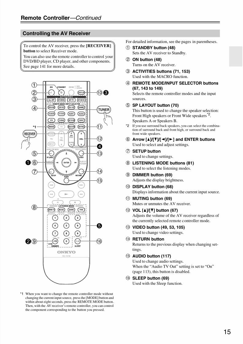
For detailed information, see the pages in parentheses.
a STANDBY button (48)
Sets the AV receiver to Standby.
b ON button (48)Turns on the AV receiver.
c ACTIVITIES buttons (71, 153)
Used with the MACRO function.
d REMOTE MODE/INPUT SELECTOR buttons
(67, 143 to 149)
Selects the remote controller modes and the inputsources.
e SP LAYOUT button (70)
This button is used to change the speaker selection:Front High speakers or Front Wide speakers*2.
Speakers A or Speakers B.*2 If you use surround back speakers, you can select the combina-
tion of surround back and front high, or surround back andfront wide speakers.
f Arrow [q]/[w]/[e]/[r] and ENTER buttons
Used to select and adjust settings.
g SETUP button
Used to change settings.
h LISTENING MODE buttons (81)
Used to select the listening modes.
i DIMMER button (69)
Adjusts the display brightness.j DISPLAY button (68)
Displays information about the current input source.
k MUTING button (69)
Mutes or unmutes the AV receiver.
l VOL [q]/[w] button (67)
Adjusts the volume of the AV receiver regardless of the currently selected remote controller mode.
m VIDEO button (49, 53, 105)
Used to change video settings.
nRETURN buttonReturns to the previous display when changing set-tings.
o AUDIO button (117)
Used to change audio settings.When the “Audio TV Out” setting is set to “On”(page 113), this button is disabled.
p SLEEP button (69)
Used with the Sleep function.
Controlling the AV Receiver
To control the AV receiver, press the [RECEIVER]
button to select Receiver mode.You can also use the remote controller to control your
DVD/BD player, CD player, and other components.See page 141 for more details.
d
c
*1
b
a
g
1f
e
h
2i
5
p
j3
4
l
k
m
n
o
*1 When you want to change the remote controller mode withoutchanging the current input source, press the [MODE] button and
within about eight seconds, press the REMOTE MODE button.Then, with the AV receiver’s remote controller, you can controlthe component corresponding to the button you pressed.

8/8/2019 Manual TX-NR5007 English
http://slidepdf.com/reader/full/manual-tx-nr5007-english 16/16416
Remote Controller—Continued
Controlling the tuner
To control the AV receiver’s tuner, press the [TUNER](or [RECEIVER]) button.You can select AM or FM by pressing the [TUNER] but-ton repeatedly.
1 Arrow [q]/[w] buttonsUsed to tune into radio stations.
2 D.TUN button (73)
(TUNER remote mode only)
Selects the Direct tuning mode.
3 DISPLAY button
Displays information about the band, frequency,preset number, and so on.
4 CH +/– button (74)
Used to select radio presets.
5 Number buttons (73, 74)Used to select radio stations directly in the Directtuning mode. Also you can select a preset directly.
Note:
An Onkyo cassette recorder connected viau can alsobe controlled in Receiver mode (see page 149).

8/8/2019 Manual TX-NR5007 English
http://slidepdf.com/reader/full/manual-tx-nr5007-english 17/16417
About Home Theater
Thanks to the AV receiver’s superb capabilities, you can enjoy surround sound with a real sense of movement in yourown home—just like being in a movie theater or concert hall. With DVDs you can enjoy DTS and Dolby Digital. Withanalog or digital TV, you can enjoy Dolby Pro Logic IIx, DTS Neo:6, or Onkyo’s original DSP listening modes.You can also enjoy THX Surround EX (THX-certified THX speaker system recommended).
Enjoying Home Theater
Front left and right speakers
These output the overall sound. Their role in a home theater is to provide
a solid anchor for the sound image. They should be positioned facing the
listener at about ear level, and equidistant from the TV. Angle them inward
so as to create a triangle, with the listener at the apex.
Center speaker
This speaker enhances the
front left and right speakers,
making sound movements dis-
tinct and providing a full sound
image. In movies it’s used
mainly for dialog.
Position it close to your TV fac-
ing forward at about ear level, or
at the same height as the frontleft and right speakers.
Subwoofer
The subwoofer handles the bass sounds
of the LFE (Low-Frequency Effects)
channel. The volume and quality of the
bass output from your subwoofer willdepend on its position, the shape of your
listening room, and your listening posi-
tion. In general, a good bass sound can
be obtained by installing the subwoofer
in a front corner, or at one-third the width
of the wall, as shown.
Tip: To find the best position for your
subwoofer, while playing a movie or
some music with good bass, experiment
by placing your subwoofer at various
positions within the room, and choose
the one that provides the most satisfying
results.
Surround left and right speakers
These speakers are used for precise sound positioning and to add
realistic ambience.
Position them at the sides of the listener, or slightly behind, about 2 to
3 feet (60 to 100 cm) above ear level. Ideally they should be equidis-
tant from the listener.
Surround back left and right speakers
These speakers are necessary to enjoy Dolby Digital
EX, DTS-ES Matrix, DTS-ES Discrete, THX Surround
EX, etc. They enhance the realism of surround sound
and improve sound localization behind the listener.
Position them behind the listener about 2 to 3 feet (60
to 100 cm) above ear level.
Front high left and right speakers
These speakers are necessary to enjoy Dolby Pro Logic IIz Height,
and Audyssey Dynamic Surround Expansion™.
They significantly enhance the spatial experience.
Position them at least 3.3 feet (100 cm) above the front left and
right speakers (preferably as high as possible) and at an angle
slightly wider than the front left and right speakers.
Corner
position
1/3 of wall
position
Front wide left and right speakers
These speakers are necessary to enjoy
Audyssey Dynamic Surround Expansion™
(DSX). They significantly enhance the spatial
experience. Position them well outside of the
front left and right speakers. See also
http://www.audyssey.com/technology/dsx.html
about optimum speaker placement for
Audyssey Dynamic Surround Expansion™.

8/8/2019 Manual TX-NR5007 English
http://slidepdf.com/reader/full/manual-tx-nr5007-english 18/16418
Connecting the AV receiver
About Speakers A and Speakers B
Speakers A and Speakers B allows you to have two speaker configurations of up to 7.2 speakers. Each configuration hasits own pair of stereo front speakers and can use the same subwoofer, center, surround, and surround back speakers, as
required. You could, for example, use Speakers A when watching a DVD movie with 7.2-channels surround sound anduse Speakers B for serious music listening with a pair of stereo speakers (2-channels).
The speakers are configured by using the “Speaker Settings” on page 57 and “Speaker Setup” on page 95.
Front Speakers A and front Speakers B can be wired normally, bi-amped, or bridged, but A and B cannot be bi-ampedor bridged at the same time. For example, if front Speakers A are bridged, front Speakers B can only be wired normally.Similarly, if front Speakers B are bi-amped, Speakers A can only be wired normally. When bridging or bi-amping isused, the AV receiver can drive up to 5.2 speakers in the main room. See pages 22 to 26 for more information.
The Speakers A and Speakers B configurations are selected by using the [SP LAYOUT] button on the remote controller.Only one configuration can be selected at a time.
The versatility offered by the Speakers A and Speakers B configurations means you can configure the AV receiver to
suit your exact requirements and application. Two typical applications are shown below.
7.2-channel Playback with Speakers A and
Stereo Playback with Speakers B
In this example, Speakers A provides 7.2-channelsurround sound for enjoying DVD movies, whileSpeakers B is used for serious music listening with apair of top-quality stereo speakers.
5.2-channel Playback with Bridged Front
Speakers
In this example, Speakers A provides 5.2-channelsurround sound for enjoying DVD movies, whileSpeakers B is bridged for use with a pair of high-power stereo speakers, the subwoofer is used withSpeakers A and Speakers B.
Connecting Your Speakers
FL C FR
FL FR
SL
SBL SBR
S W 1
S W 2
SR
Speakers A
Speakers B
Speaker ImpedanceSpeakers Type(FrontA)
Speakers Type(FrontB)Powered Zone2Powered Zone3
6ohmsNormal
NormalNot ActNot Act
2–1. Speaker Settings
2–2. Speaker Configurati on
SubwooferFrontCenterSurroundSurr Back
UseUseUseUseUse
Speaker A
SubwooferFrontCenterSurround
Surr Back
Not UseUse
Not UseNot Use
Not Use
Speaker B
2–2. Speaker Configurati on
FL C FR
FL FR
SL SR
S W 1
S W 2
Speakers A
Speakers B
Subwoofer
used with A
and B
Speaker Impedance
Speakers Type(FrontA)Speakers Type(FrontB)Powered Zone2Powered Zone3
8ohms
NormalBTL
Not ActNot Act
2–1. Speaker Settings
SubwooferFrontCenterSurroundSurr Back
UseUseUseUse
Not Use
Speaker A
2–2. Speaker Configurati on
SubwooferFrontCenter
SurroundSurr Back
UseUse
Not Use
Not UseNot Use
Speaker B
2–2. Speaker Configurati on

8/8/2019 Manual TX-NR5007 English
http://slidepdf.com/reader/full/manual-tx-nr5007-english 19/16419
Connecting the AV receiver—Continued
Speaker Configuration
For 9.2-channel surround-sound playback, you need nine speakers and two powered subwoofers.The following table indicates the channels you should use depending on the number of speakers that you have.
* If you’re using only one surround back speaker, connect it to the SURR BACK/ZONE 3 L terminal.
No matter how many speakers you use, two powered subwoofers are recommended for a really powerful and solid bass.To get the best from your surround sound system, you need to set the speaker settings. You can do this automatically(see page 61) or manually (see page 95).
Note:
Front high and front wide speakers produce no sound at the same time.
Attaching the Speaker Labels
The AV receiver’s positive (+) speaker terminals are allred (the negative (–) speaker terminals are all black).
The supplied speaker cable labels are also color-codedand you should attach them to the positive (+) side of each speaker cable in accordance with the above table.Then all you need to do is to match the color of eachlabel to the corresponding speaker terminal.
(North American models)
• If you are using banana plugs, tighten the speaker ter-
minal before inserting the banana plug.• Do not insert the speaker code directly into the centerhole of the speaker terminal.
Connecting Powered Subwoofers
Using a suitable cable, connect the AV receiver’s PREOUT: SW1, SW2 to an input on your powered sub-woofer, as shown. If your subwoofer is unpowered andyou’re using an external amplifier, connect the PREOUT: SW1, SW2 to an input on the amp.You can connect the powered subwoofer with each jacksrespectively. Level and distance can be set individuallyfor each output. If you use one subwoofer, connect it toPRE OUT: SW1.
Number of speakers: 2 3 4 5 6 7 7 7 8 8 9 9 9 10 11
Front left
Front right
Center
Surround left
Surround right
Surround back*
Surround back left
Surround back right
Front high left
Front high right
Front wide left
Front wide right
Speaker Color
Front left White
Front right Red
Center Green
Surround left Blue
Surround right Gray
Surround back left, Zone 3 left Brown
Surround back right, Zone 3 right Tan
Front high left White
Front high right RedFront wide left, Zone 2 left White
Front wide right, Zone 2 right Red
LINEINPUT
LINE INPUT
LINEINPUT
LINE INPUT
Powered subwoofer

8/8/2019 Manual TX-NR5007 English
http://slidepdf.com/reader/full/manual-tx-nr5007-english 20/16420
Connecting the AV receiver—Continued
Using Dipole Speakers
You can use dipole speakers for the surround left andright, surround back left and right speakers. Dipolespeakers output the same sound in two directions.Dipole speakers typically have an arrow printed on them
to indicate how they should be positioned. The surroundleft and right dipole speakers should be positioned sothat their arrows point toward the TV/screen, while thesurround back left and right and front high left and rightand front wide left and right dipole speakers should bepositioned so that their arrows point toward each other,as shown.
Speaker Connection Precautions
Read the following before connecting your speakers:• You can connect speakers with an impedance of
between 4 and 16 ohms. If the impedance of any of theconnected speakers is 4 ohms or more, but less than 6
ohms, be sure to set the minimum speaker impedanceto “4ohms” (see page 57). If you use speakers with alower impedance, and use the amplifier at high vol-ume levels for a long period of time, the built-in pro-tection circuit may be activated.
• Disconnect the power cord from the wall outlet beforemaking any connections.
• Read the instructions supplied with your speakers.• Pay close attention to speaker wiring polarity. In other
words, connect positive (+) terminals only to positive(+) terminals, and negative (–) terminals only to nega-
tive (–) terminals. If you get them the wrong wayaround, the sound will be out of phase and will soundunnatural.
• Unnecessarily long, or very thin speaker cables mayaffect the sound quality and should be avoided.
• If you use 4 or 5 speakers, connect each of the twosurround speakers to the SURR L/R terminals. Do notconnect them to the SURR BACK/ZONE 3 L/R,FRONT WIDE/ZONE 2 L/R, or FRONT HIGH L/Rterminals.
• Be careful not to short the
positive and negative wires.Doing so may damage the AVreceiver.
• Make sure the metal core of the wire does not have contactwith the AV receiver’s rearpanel. Doing so may damage the AV receiver.
• Don’t connect more than one cable to each speakerterminal. Doing so may damage the AV receiver.
• Don’t connect one speaker to several terminals.
1 1
5 6
7 8
2 3 4
5
7 8
6
1
9 10
11 122 3 4
9 10
11 12
1TV/screen TV/screen
1. Subwoofers
2. Front left speaker
3. Center speaker
4. Front right speaker
5. Surround left speaker
6. Surround right speaker
7. Surround back left
speaker
8. Surround back right
speaker
9. Front high left speaker
10.Front high right speaker
11.Front wide left speaker
12.Front wide right speaker
Dipole speakers Normal speakers

8/8/2019 Manual TX-NR5007 English
http://slidepdf.com/reader/full/manual-tx-nr5007-english 21/16421
Connecting the AV receiver—Continued
Connecting the Speaker Cables
9.2-channel Playback with Speakers A
The following illustration shows which speaker should be connected to each pair of terminals. If you’re using only onesurround back speaker, connect it to the SURR BACK/ZONE 3 L terminal.
1 Strip 1/2" to 5/8" (12 to
15 mm) of insulation
from the ends of the
speaker cables, and
twist the bare wires
tightly, as shown.
2 Unscrew the terminal.
1/2" to 5/8"
(12 to 15 mm)3 Fully insert the bare
wires.
4 Screw the terminal tight.
Surroundback leftspeaker
Surroundback rightspeaker
Surroundleft
speaker
Surroundright
speaker
Front highleft
speaker
Front highright
speakerFront left
speaker AFront rightspeaker A
Centerspeaker
Front wideright
speakerFront wide left
speaker

8/8/2019 Manual TX-NR5007 English
http://slidepdf.com/reader/full/manual-tx-nr5007-english 22/16422
Connecting the AV receiver—Continued
7.2-channel Playback with Speakers A or Speakers B
The following illustration shows which speaker should be connected to each pair of terminals for up to 7.2-channelplayback with Speakers A or Speakers B. If you’re using only one surround back speaker, connect it to the SURRBACK/ZONE 3 L terminal.
Notes:
• When Speakers A is selected as the main front speakers, connect the front left speaker to FRONT L, front rightspeaker to FRONT R. When Speakers B is selected as the main front speakers, connect the front left speaker toFRONT WIDE/ZONE 2 L, front right speaker to FRONT WIDE/ZONE 2 R.
• The speakers are configured by using the “Speaker Settings” on page 57 and “Speaker Setup” on page 95.• You can choose which of the spakers you want to use with the Speakers A or Speakers B configuration (see page 96).• When you use the Speakers B configuration, front high speakers cannnot be used.
Surroundback leftspeaker
Surroundback rightspeaker
Surroundleft
speaker
Surroundright
speaker
Front leftspeaker A
Front rightspeaker A
Centerspeaker
Front rightspeaker B
Front leftspeaker B

8/8/2019 Manual TX-NR5007 English
http://slidepdf.com/reader/full/manual-tx-nr5007-english 23/16423
Connecting the AV receiver—Continued
The FRONT L/R and SURR BACK/ZONE 3 L/R termi-nal posts can be used with front speakers and surroundback speakers respectively, or bi-amped to provide sepa-rate tweeter and woofer feeds for a pair of front speakersA that support bi-amping, providing improved bass andtreble performance.• When bi-amping is used, surround back speakers can-
not be used.• For bi-amping, the FRONT L/R terminal posts con-
nect to the front speakers’ woofer terminals. And theSURR BACK/ZONE 3 L/R terminal posts connect tothe front speakers’ tweeter terminals.
• Once you’ve completed the bi-amping connectionsshown below and turned on the AV receiver, you mustset the “Speakers Type(FrontA)” setting to “Bi-Amp”
to enable biamping (see page 57).• When front Speakers A are biamped, front Speakers B
must be wired normally or not used.
Important:
• When making the bi-amping connections, be sure
to remove the jumper bars that link the Speakers’
tweeter (high) and woofer (low) terminals.
• Bi-amping can only be used with speakers that supportbi-amping. Refer to your speaker manual.
Bi-amping Speaker Hookup Bi-amping the Front Speakers A
1 Connect the AV receiver’s FRONT R positive (+)terminal to the right speaker’s positive (+) Woofer(low) terminal. And connect the AV receiver’s
FRONT R negative (–) terminal to the rightspeaker’s negative (–) Woofer (low) terminal.
2 Connect the AV receiver’s SURR BACK/ZONE 3R positive (+) terminal to the right speaker’s pos-itive (+) Tweeter (high) terminal. And connect theAV receiver’s SURR BACK/ZONE 3 R negative(–) terminal to the right speaker’s negative (–)Tweeter (high) terminal.
3 Connect the AV receiver’s FRONT L positive (+)terminal to the left speaker’s positive (+) Woofer
(low) terminal. And connect the AV receiver’sFRONT L negative (–) terminal to the leftspeaker’s negative (–) Woofer (low) terminal.
4 Connect the AV receiver’s SURR BACK/ZONE 3L positive (+) terminal to the left speaker’s posi-tive (+) Tweeter (high) terminal. And connect theAV receiver’s SURR BACK/ZONE 3 L negative(–) terminal to the left speaker’s negative (–)Tweeter (high) terminal.
Woofer (low)
Tweeter (high)Tweeter (high)
Woofer (low)
Left speakerRight speaker

8/8/2019 Manual TX-NR5007 English
http://slidepdf.com/reader/full/manual-tx-nr5007-english 24/16424
Connecting the AV receiver—Continued
The FRONT L/R and SURR BACK/ZONE 3 L/R ter-minal posts can be used with front speakers and surroundback speakers respectively, or bridged together to pro-vide almost double the output power for the frontspeakers A.
• When bridging is used, surround back speakers cannotbe used.
• For bridging, the positive (+) FRONT L/R and SURRBACK/ZONE 3 L/R terminal posts are used, but thenegative (–) FRONT L/R and SURR BACK/ZONE 3L/R terminals are not.
• Once you’ve completed the bridging connectionsshown below and turned on the AV receiver, you mustset the “Speakers Type(FrontA)” setting to “BTL” toenable bridging (see page 57).
• When front Speakers A are bridged, front Speakers Bmust be wired normally or not used.
Notes:
• Use only front speakers with an impedance of 8
ohms or higher for bridging. Failure to do so may
seriously damage the AV receiver.
• When using bridging, make sure that your front speak-ers can handle the additional power.
Bridged Speaker Hookup Bridging the Front Speakers A
1 Connect the AV receiver’s FRONT R positive (+)terminal to the right speaker’s positive (+) ter-minal. And connect the AV receiver’s SURR
BACK/ZONE 3 R positive (+) terminal to theright speaker’s negative (–) terminal.
2 Connect the AV receiver’s FRONT L positive (+)terminal to the left speaker’s positive (+) terminal.And connect the AV receiver’s SURRBACK/ZONE 3 L positive (+) terminal to the leftspeaker’s negative (–) terminal.
Right speaker Left speaker

8/8/2019 Manual TX-NR5007 English
http://slidepdf.com/reader/full/manual-tx-nr5007-english 25/16425
Connecting the AV receiver—Continued
The FRONT WIDE/ZONE 2 L/R and SURRBACK/ZONE 3 L/R terminal posts can be used withfront wide speakers and surround back speakers respec-tively, or bi-amped to provide separate tweeter andwoofer feeds for a pair of front speakers B that supportbi-amping, providing improved bass and treble perfor-mance.• When bi-amping is used, surround back speakers can-
not be used.• For bi-amping, the FRONT WIDE/ZONE 2 L/R ter-
minal posts connect to the front speakers’ woofer ter-minals. And the SURR BACK/ZONE 3 L/R terminalposts connect to the front speakers’ tweeter terminals.
• Once you’ve completed the bi-amping connectionsshown below and turned on the AV receiver, you must
set the “Speakers Type(FrontB)” setting to “Bi-Amp”to enable biamping (see page 57).
• When front Speakers B are biamped, front Speakers Amust be wired normally.
Important:
• When making the bi-amping connections, be sure
to remove the jumper bars that link the Speaker’s
tweeter (high) and woofer (low) terminals.
• Bi-amping can only be used with speakers that supportbi-amping. Refer to your speaker manual.
Bi-amping Speaker Hookup Bi-amping the Front Speakers B
1 Connect the AV receiver’s FRONTWIDE/ZONE 2 R positive (+) terminal to theright speaker’s positive (+) Woofer (low) termi-
nal. And connect the AV receiver’s FRONTWIDE/ZONE 2 R negative (–) terminal to theright speaker’s negative (–) Woofer (low) termi-nal.
2 Connect the AV receiver’s SURR BACK/ZONE 3R positive (+) terminal to the right speaker’s pos-itive (+) Tweeter (high) terminal. And connect theAV receiver’s SURR BACK/ZONE 3 R negative(–) terminal to the right speaker’s negative (–)Tweeter (high) terminal.
3 Connect the AV receiver’s FRONTWIDE/ZONE 2 L positive (+) terminal to the leftspeaker’s positive (+) Woofer (low) terminal. Andconnect the AV receiver’s FRONTWIDE/ZONE 2 L negative (–) terminal to the leftspeaker’s negative (–) Woofer (low) terminal.
4 Connect the AV receiver’s SURR BACK/ZONE 3L positive (+) terminal to the left speaker’s posi-tive (+) Tweeter (high) terminal. And connect theAV receiver’s SURR BACK/ZONE 3 L negative(–) terminal to the left speaker’s negative (–)
Tweeter (high) terminal.
Woofer (low)
Tweeter (high)Tweeter (high)
Woofer (low)
Left speakerRight speaker

8/8/2019 Manual TX-NR5007 English
http://slidepdf.com/reader/full/manual-tx-nr5007-english 26/16426
Connecting the AV receiver—Continued
The FRONT WIDE/ZONE 2 L/R and SURRBACK/ZONE 3 L/R terminal posts can be used withfront wide speakers and surround back speakers respec-tively, or bridged together to provide almost double theoutput power for the front speakers B.
• When bridging is used, surround back speakers cannotbe used.
• For bridging, the positive (+) FRONT WIDE/ZONE 2L/R and SURR BACK/ZONE 3 L/R terminal postsare used, but the negative (–) FRONT WIDE/ZONE 2L/R and SURR BACK/ZONE 3 L/R terminals are not.
• Once you’ve completed the bridging connectionsshown below and turned on the AV receiver, you mustset the “Speakers Type(FrontB)” setting to “BTL” toenable bridging (see page 57).
• When front Speakers B are bridged, front Speakers Amust be wired normally.
Notes:
• Use only front speakers with an impedance of 8
ohms or higher for bridging. Failure to do so may
seriously damage the AV receiver.
• When using bridging, make sure that your front speak-ers can handle the additional power.
Bridged Speaker Hookup Bridging the Front Speakers B
1 Connect the AV receiver’s FRONTWIDE/ZONE 2 R positive (+) terminal to theright speaker’s positive (+) terminal. And connect
the AV receiver’s SURR BACK/ZONE 3 R posi-tive (+) terminal to the right speaker’s negative(–) terminal.
2 Connect the AV receiver’s FRONTWIDE/ZONE 2 L positive (+) terminal to the leftspeaker’s positive (+) terminal. And connect theAV receiver’s SURR BACK/ZONE 3 L positive(+) terminal to the left speaker’s negative (–) ter-minal.
Right speaker Left speaker

8/8/2019 Manual TX-NR5007 English
http://slidepdf.com/reader/full/manual-tx-nr5007-english 27/16427
Connecting the AV receiver—Continued
This section explains how to connect the supplied indoorFM antenna and AM loop antenna, and how to connectcommercially available outdoor FM and AM antennas.The AV receiver won’t pick up any radio signals without
any antenna connected, so you must connect the antennato use the tuner.
Connecting the Indoor FM Antenna
The supplied indoor FM antenna is for indoor use only.
If you cannot achieve good reception with the suppliedindoor FM antenna, try a commercially available out-door FM antenna instead (see page 28).
Connecting the AM Loop Antenna
The supplied indoor AM loop antenna is for indoor useonly.
If you cannot achieve good reception with the suppliedindoor AM loop antenna, try using it with a commer-cially available outdoor AM antenna (see page 28).
Connecting Antenna
1 Attach the FM antenna, as shown.
(North American models)
(European and Asian models)
Once your AV receiver is ready for use, you’llneed to tune into an FM radio station and adjustthe position of the FM antenna to achieve the bestpossible reception.
2 Use thumbtacks or something similar to
fix the FM antenna into position.
Caution:
Be careful that you don’t injure yourself whenusing thumbtacks.
FM ANTENNA jack
AM ANTENNA push terminals
Insert the plug fully
into the jack.
Insert the plug fully
into the jack.
Thumbtacks, etc.
1 Assemble the AM loop antenna, inserting
the tabs into the base, as shown.
2 Connect both wires of the AM loop
antenna to the AM antenna push termi-
nals, as shown.
(The antenna’s wires are not polarity sensitive, sothey can be connected either way around.)Make sure that the wires are attached securely andthat the push terminals are gripping the barewires, not the insulation.
Once your AV receiver is ready for use, you’llneed to tune into an AM radio station and adjustthe position of the AM antenna to achieve the bestpossible reception.Keep the antenna as far away as possible from
your AV receiver, TV, speaker cables, and powercords.
Push Insert wire Release

8/8/2019 Manual TX-NR5007 English
http://slidepdf.com/reader/full/manual-tx-nr5007-english 28/16428
Connecting the AV receiver—Continued
Connecting an Outdoor FM Antenna
If you cannot achieve good reception with the suppliedindoor FM antenna, try a commercially available out-door FM antenna instead.
Notes:
• Outdoor FM antennas work best outside, but usableresults can sometimes be obtained when installed in anattic or loft.
• For best results, install the outdoor FM antenna well
away from tall buildings, preferably with a clear lineof sight to your local FM transmitter.• Outdoor antenna should be located away from possi-
ble noise sources, such as neon signs, busy roads, etc.• For safety reasons, outdoor antenna should be situated
well away from power lines and other high-voltageequipment.
• Outdoor antenna must be grounded in accordancewith local regulations to prevent electrical shock haz-ards.
Using a TV/FM Antenna Splitter
It’s best not to use the same antenna for both FM and TVreception, as this can cause interference problems. If cir-cumstances demand it, use a TV/FM antenna splitter, asshown.
Connecting an Outdoor AM Antenna
If good reception cannot be achieved using the suppliedAM loop antenna, an outdoor AM antenna can be usedin addition to the loop antenna, as shown.
Outdoor AM antennas work best when installed outsidehorizontally, but good results can sometimes be obtainedindoors by mounting horizontally above a window. Note
that the outdoor antenna should be right connected.Outdoor antenna must be grounded in accordance withlocal regulations to prevent electrical shock hazards.
To AV receiver To TV (or VCR)
TV/FM antenna splitter
Outdoor antenna
Insulated antenna cable
AM loop antenna

8/8/2019 Manual TX-NR5007 English
http://slidepdf.com/reader/full/manual-tx-nr5007-english 29/16429
Connecting the AV receiver—Continued
• Before making any AV connections, read the manualssupplied with your other AV components.
• Don’t connect the power cord until you’ve completedand double-checked all AV connections.
Optical Digital Jacks
The AV receiver’s optical digital jacks have shutter-typecovers that open when an optical plug is inserted andclose when it’s removed. Push plugs in all the way.
Caution:
To prevent shutter damage, hold the optical plug straightwhen inserting and removing.
AV Connection Color Coding
RCA-type AV connections are usually color-coded: red,white, and yellow. Use red plugs to connect right-chan-nel audio inputs and outputs (typically labeled “R”). Usewhite plugs to connect left-channel audio inputs and out-
puts (typically labeled “L”). And use yellow plugs toconnect composite video inputs and outputs.
• Push plugs in all the way to makegood connections (loose connec-tions can cause noise or malfunc-tions).
• To prevent interference, keepaudio and video cables away frompower cords and speaker cables.
AV Cables & Jacks
The AV receiver does not support SCART plugs.
About AV Connections
Analog audio
Composite video
Left (white)
Right (red) Right (red)
Left (white)
(Yellow)(Yellow)
Right!
Wrong!
Video / Audio
Cable Jack Description
HDMI
HDMI connections can carry uncompressed stan-dard- or high-definition digital video and audio andoffer the best picture and sound quality.
Video
Componentvideo cable
Component video separates the luminance (Y) andcolor difference signals (PR, PB), providing the bestpicture quality (some TV manufacturers label theircomponent video sockets slightly differently).
S-Video cableS-Video separates the luminance and color signals and
provides better picture quality than composite video.
Compositevideo cable
Composite video is commonly used on TVs, VCRs,and other video equipment.
Audio
Optical digitalaudio cable
Offers the best sound quality and allows you toenjoy surround sound (e.g., Dolby Digital, DTS).The audio quality is the same as for coaxial.
Coaxial digitalaudio cable
Offers the best sound quality and allows you toenjoy surround sound (e.g., Dolby Digital, DTS).The audio quality is the same as for optical.
Analog audiocable (RCA)
This cable carries analog audio. It’s the most com-mon connection format for analog audio, and can befound on virtually all AV components.
Multichannelanalog audiocable (RCA)
This cable carries multichannel analog audio and is
typically used to connect DVD players with a 7.1-channel analog audio output. Several standard ana-log audio cables can be used instead of a multichan-nel cable.
HDMI
Y
PB /CB
PR /CR
Y
PB /CB
PR /CR
V
OPTICAL
L
R

8/8/2019 Manual TX-NR5007 English
http://slidepdf.com/reader/full/manual-tx-nr5007-english 30/16430
Connecting the AV receiver—Continued
About HDMI
Designed to meet the increased demands of digital TV, HDMI (High Definition Multimedia Interface) is a new digitalinterface standard for connecting TVs, projectors, DVD/BD players, set-top boxes, and other video components. Until
now, several separate video and audio cables have been required to connect AV components. With HDMI, a single cablecan carry control signals, digital video, and up to eight channels of digital audio (2-channel PCM, multichannel digitalaudio, and multichannel PCM).The HDMI video stream (i.e., video signal) is compatible with DVI (Digital Visual Interface)*1, so TVs and displayswith a DVI input can be connected by using an HDMI-to-DVI adapter cable. (This may not work with some TVs anddisplays, resulting in no picture.)The AV receiver uses HDCP (High-bandwidth Digital Content Protection)*2, so only HDCP-compatible componentscan display the picture.
Supported Audio Formats
• 2-channel linear PCM (32–192 kHz, 16/20/24 bit)• Multichannel linear PCM (up to 7.1 ch, 32–192 kHz, 16/20/24 bit)• Bitstream (DSD, Dolby Digital, Dolby Digital Plus, Dolby TrueHD, DTS, DTS Express, DTS-HD High Resolution
Audio, DTS-HD Master Audio)Your DVD/BD players must also support HDMI output of the above audio formats.
Onkyo for System Control
, which stands for Remote Interactive over HDMI, is the name of the system control function found on Onkyocomponents. The AV receiver can be used with CEC (Consumer Electronics Control), which allows system control overHDMI and is part of the HDMI standard. CEC provides interoperability between various components, however, opera-tion with components other than -compatible components cannot be guaranteed.• Set “HDMI Control (RIHD)” to “On” (page 114).• See “Controlling a TV” (page 143) and “Controlling a DVD Player or DVD Recorder” (page 144) for operation.
Notes:
• Do not connect the -compatible component more than the following number to the HDMI input terminal sothat the linked operations work properly.
a. DVD/BD player is up to three.b. DVD/BD recorder is up to three.c. Cable/Satellite Set-top box is up to four.
• Do not connect the AV receiver to the other AV receiver /AV amplifier via HDMI.• When the -compatible component more than the above-mentioned is connected, the linked operations are
not guaranteed.• The control does not support HDMI OUT SUB. Use HDMI OUT MAIN instead.
About Copyright Protection
The AV receiver supports HDCP (High-bandwidth Digital Content Protection)*2, a copy-protection system for digitalvideo signals. Other devices connected to the AV receiver via HDMI must also support HDCP.
*1 DVI (Digital Visual Interface): The digital display interface standard set by the DDWG*3 in 1999.*2 HDCP (High-bandwidth Digital Content Protection): The video encryption technology developed by Intel for HDMI/DVI. It’s designed to
protect video content and requires a HDCP-compatible device to display the encrypted video. *3 DDWG (Digital Display Working Group): Lead by Intel, Compaq, Fujitsu, Hewlett Packard, IBM, NEC, and Silicon Image, this openindustry group’s objective is to address the industry’s requirements for a digital connectivity specification for high-performance PCs anddigital displays.
Connecting Components with HDMI
The AV receiver’s HDMI interface is based on the following standard:x.v.Color, Deep Color, Lip Sync, DTS-HD Master Audio, DTS-HD High Resolution Audio, Dolby TrueHD, Dolby
Digital Plus, DSD, and Multichannel PCM

8/8/2019 Manual TX-NR5007 English
http://slidepdf.com/reader/full/manual-tx-nr5007-english 31/16431
Connecting the AV receiver—Continued
Making HDMI Connections
Video Signals
Digital video signals received by the HDMI IN jacks are normally output by the HDMI MAIN OUT and SUB OUT fordisplay on your TV. Composite video, S-Video, and component video sources can be upconverted for the HDMI output.See “Video Connection Formats” on page 32 for more information.
Audio Signals
Digital audio signals received by the HDMI IN jacks are output by the speakers and headphones connected to the AVreceiver. Normally, they are not output by the HDMI outputs, unless the “Audio TV Out” setting is set to “On” (see
page 113).To listen to audio received by the HDMI IN jacks through your TV’s speakers:•Set the “TV Control” setting to “On” (see page 114) for an -compatible TV.•Set the “Audio TV Out” setting to “On” (see page 113) when the TV is not compatible withor the “TV Control” setting to “Off”.
•Set your DVD/BD player’s HDMI audio output setting to PCM.
Notes:• The HDMI video stream is compatible with DVI (Digital Visual Interface), so TVs and displays with a DVI input can
be connected by using an HDMI-to-DVI adapter cable. (Note that DVI connections only carry video, so you’ll needto make a separate connection for audio.) However, reliable operation with such an adapter is not guaranteed. Inaddition, video signals from a PC are not guaranteed.
• When listening to an HDMI component through the AV receiver, set the HDMI component so that its video can beseen on the TV screen (on the TV, select the input of the HDMI component connected to the AV receiver). If the TVpower is off or the TV is set to another input source, this may result in no sound from the AV receiver or the soundmay be cut off.
• When the “Audio TV Out” setting is set to “On” (see page 113) to hear from your TV’s speakers, by controlling theAV receiver’s volume, the sound will be output from the AV receiver’s speakers, too. When the “TV Control” settingis set to “On” to hear from speakers of -compatible TV, by controlling the AV receiver’s volume, the AV
receiver’s speakers will produce sound while the TV’s speakers are muted. To stop the AV receiver’s speakers pro-ducing sound, change the settings, change your TV’s settings, or turn down the AV receiver’s volume.• The HDMI audio signal (sampling rate, bit length, etc.) may be restricted by the connected source component. If the
picture is poor or there’s no sound from a component connected via HDMI, check its setup. Refer to the connectedcomponent’s instruction manual for details.
Step 1:
Use HDMI cables to connect the AV receiver’s HDMI jacks to your HDMI-compatible DVD/BD player, TV, projec-tor, and so on.
Step 2:
Assign each HDMI IN to an input selector in the HDMI Input Setup (see page 54).
Hint!
HDMIIN
HDMIOUT
TV
DVD/BD player
HD camcorder, etc

8/8/2019 Manual TX-NR5007 English
http://slidepdf.com/reader/full/manual-tx-nr5007-english 32/16432
Connecting the AV receiver—Continued
By connecting both the audio and video outputs of your DVD/BD player and other AV components to the AV receiver,you can select both the audio and video simultaneously simply by selecting the appropriate input source on the AVreceiver.
The AV receiver supports several connection formats for compatibility with a wide range of AV equipment. The formatyou choose will depend on the formats supported by your other components. Use the following sections as a guide.
Video Connection Formats
Video equipment can be connected to the AV receiver by using any one of the following video connection formats:composite video, S-Video, component video, or HDMI, the latter offering the best picture quality.The AV receiver can upconvert and downconvert between video formats, depending on the “Monitor Out” setting, whichgenerally determines whether video signals are upconverted for the component video output or the HDMI output.For optimal video performance, THX recommends that video signals pass through the system without upconver-
sion (e.g., component video input through to component video output).
It is also recommended that you press the [VCR/DVR] and [RETURN] buttons on the AV receiver at the same
time. Select “Skip” in the “VideoProcessor” setting by pressing the [RETURN] button repeatedly on the display.
To reset back to the original setting, press the same button at the same time.
“Monitor Out” Setting Set to “HDMI Main” or “HDMI Sub”
With the “Monitor Out” setting set to “HDMIMain” or “HDMI Sub” (see page 52), video inputsignals flow through the AV receiver as shown,with composite video, S-Video, and componentvideo sources all being upconverted for theHDMI output. Use the “HDMI Main” or
“HDMI Sub” setting if you connect the AV
receiver’s HDMI OUT MAIN or HDMI OUT
SUB, respectively, to your TV.
The composite video, S-Video, and componentvideo outputs pass through their respective inputsignals as they are.
Note:
If not connected to the same output you haveselected in the “Monitor Out” setting, the “Mon-itor Out” setting will be automatically switchedto “Analog” (see page 52). In this case, the set-
ting of the output resolution will be that for HDMI output (see page 52). However, it will be switched to “1080i” when“1080p” is selected, and to “Through” when “Auto” is selected.
Connecting Both Audio & Video
: Signal Flow
Video
Audio
Video
Audio
Speakers
(see page 21 for connection information)
DVD/BD player, etc.
TV, projector,
etc.
Which Connections Should I Use?
IN
MONITOR OUT
DVD/BD player, etc.
AV receiver
TV, projector, etc.
Composite
Composite
S-Video
S-Video
Component
Component
Video Signal Flow Chart
HDMI
HDMI

8/8/2019 Manual TX-NR5007 English
http://slidepdf.com/reader/full/manual-tx-nr5007-english 33/16433
Connecting the AV receiver—Continued
“Monitor Out” Setting Set to “Both”, “Both(Main)” or “Both(Sub)”
With the “Monitor Out” setting set to “Both”,“Both(Main)” or “Both(Sub)” (see page 52),video input signals flow through the AV receiveras shown, with composite video, S-Video, andcomponent video sources all being upconverted
for both HDMI outputs. Use the “Both”,“Both(Main)” or “Both(Sub)” setting if youconnect the AV receiver’s HDMI OUT MAINand HDMI OUT SUB to your TVs.
The composite video, S-Video, and componentvideo outputs pass through their respective inputsignals as they are.Both: Video signals are output from both HDMIoutputs at the resolution supported by both TVs.You cannot select “Resolution” setting. The pic-ture adjust setting will be that for “HDMI Main”.Both (Main): Video signals are output from bothHDMI outputs but HDMI OUT MAIN willbecome a priority; depending on the resolution, video signals may not be output from HDMI OUT SUB.Both (Sub): Video signals are output from both HDMI outputs but HDMI OUT SUB will become a priority; dependingon the resolution, video signals may not be output from HDMI OUT MAIN.Note:The “Monitor Out” setting will be automatically switched to “Analog” (see page 52) if not connected to both outputswhen “Both” is selected or if not connected to a priority output when “Both(Main)” or “Both(Sub)” is selected.
“Monitor Out” Setting Set to “Analog”
With the “Monitor Out” setting set to “Analog”(see page 52), video input signals flow throughthe AV receiver as shown, with composite videoand S-Video sources being upconverted for thecomponent video output. Use this setting if you
connect the AV receiver’s COMPONENTVIDEO MONITOR OUT to your TV.
Composite video is upconverted to S-Video andS-Video is downconverted to composite video.Note that these conversions only apply to theMONITOR OUT V and S outputs, not theVCR/DVR OUT V and S outputs.The composite video, S-Video, and componentvideo outputs pass through their respective inputsignals as they are.This signal flow also applies when the “Resolu-tion” setting is set to “Through” (see page 52).
Video Signal Flow and the Resolution SettingWhen the “Monitor Out” setting is set to “Ana-log” (see page 52), if the “Resolution” setting isset to anything other than “Through” (seepage 52), the video signal flow will be as shownhere, with composite video and S-Video sourcesbeing upconverted for the component video out-put.The composite video, S-Video, and componentvideo outputs pass through their respective ana-log input signals as they are. HDMI input signals
are not output.
IN
MONITOR OUT
DVD/BD player, etc.
AV receiver
TV, projector, etc.
Composite
Composite
S-Video
S-Video
Component
Component
Video Signal Flow Chart
HDMI
HDMI
IN
MONITOR OUT
DVD/BD player, etc.
AV receiver
TV, projector, etc.
Composite
Composite
S-Video
S-Video
Component
Component
Video Signal Flow Chart
HDMI
HDMI
IN
MONITOR OUT
DVD/BD player, etc.
AV receiver
TV, projector, etc.
Composite
Composite
S-Video
S-Video
Component
Component
Video Signal Flow Chart
HDMI
HDMI

8/8/2019 Manual TX-NR5007 English
http://slidepdf.com/reader/full/manual-tx-nr5007-english 34/16434
Connecting the AV receiver—Continued
Audio Connection Formats
Audio equipment can be connected to the AVreceiver by using any of the following audio con-nection formats: analog, optical, coaxial, analogmultichannel, or HDMI.When choosing a connection format, bear inmind that the AV receiver does not convert digitalinput signals for analog line outputs and viceversa. For example, audio signals connected toan optical or coaxial digital input are not outputby the analog TV/TAPE OUT.
If signals are present at more than one input, the inputs will be selected automatically in the following order of priority:HDMI, digital, analog.
*1
DVD/BD player, etc.
AV receiver
TV, projector, etc.
Audio Signal Flow Chart
HDMIAnalog
*1 Depends on the “Audio TV Out” setting (seepage 113).
*2 Only the front L/R channels are output.
Optical CoaxialMultichannelAnalog HDMI

8/8/2019 Manual TX-NR5007 English
http://slidepdf.com/reader/full/manual-tx-nr5007-english 35/16435
Connecting the AV receiver—Continued
See “Connecting Components with HDMI” on page 30 for HDMI connection information.
• With connection , you can listen to and record audio from your TV or listen in Zone 2 or Zone 3.
• To enjoy Dolby Digital and DTS, use connection or . (To record or listen in Zone 2 or Zone 3 as well, useand , or and .)
If your TV has no audio outputs, connect an audio output from your VCR or cable or satellite receiverto the AV receiver and use its tuner to listen to TV programs through the AV receiver (see pages 38 and40).
Connecting a TV or Projector
Connection AV receiver Signal flow TV, projector, etc.
COMPONENT VIDEO MONITOR OUT ⇒ Component video input
MONITOR OUT S ⇒ S-Video input
MONITOR OUT V ⇒ Composite video input
TV/TAPE IN L/R ⇐ Analog audio L/R output
DIGITAL COAXIAL IN 2 (VCR/DVR) ⇐ Digital coaxial output
DIGITAL OPTICAL IN 1 (GAME) (TX-NR3007)DIGITAL OPTICAL IN 2 (TV/TAPE) (TX-NR5007)
⇐ Digital optical output
Step 1: Video Connection
Choose a video connection that matches your TV ( , , or ), and then make the connection.A B C
Step 2: Audio Connection
Choose an audio connection that matches your TV ( , , or ), and then make the connection.a b c
a
b c
a b a c
A
B
C
a
b
c
COAXIALOUT
OPTICALOUT
AUDIOOUT
L R
S VIDEOIN
VIDEOIN COMPONENT VIDEO IN
Y PB PR
a
A
C
B
b c
TV, projector,
etc.
When you use connection ,
you need to assign the digital
audio input (see page 56).
b
(TX-NR3007) When you use connection ,
you need to assign the digital audio input
(see page 56).
c
Hint!

8/8/2019 Manual TX-NR5007 English
http://slidepdf.com/reader/full/manual-tx-nr5007-english 36/16436
Connecting the AV receiver—Continued
See “Connecting Components with HDMI” on page 30 for HDMI connection information.
• With connection , you can listen to and record audio from your DVD player or listen in Zone 2 or Zone 3.
• To enjoy Dolby Digital and DTS, use connection or . (To record or listen in Zone 2 or Zone 3 as well, useand , or and .)
• If your DVD player has main left and right outputs and multichannel left and right outputs, be sure to use themain left and right outputs for connection .
Connecting a DVD Player
Connection AV receiver Signal flow DVD player
COMPONENT VIDEO IN 1 (DVD/BD) ⇐ Component video output
DVD/BD IN S ⇐ S-Video output
DVD/BD IN V ⇐ Composite video output
DVD/BD IN L/R ⇐ Analog audio L/R output
DIGITAL COAXIAL IN 1 (DVD/BD) ⇐ Digital coaxial output
DIGITAL OPTICAL IN 1 (GAME) ⇐ Digital optical output
Step 1: Video Connection
Choose a video connection that matches your DVD player ( , , or ), and then make the connection.
You must connect the AV receiver to your TV via the same type of connection.
A B C
Step 2: Audio Connection
Choose an audio connection that matches your DVD player ( , , or ), and then make the connection.a b c
a
b c
a b a c
a
A
B
C
a
b
c
COAXIALOUT
OPTICALOUT
AUDIOOUT
L R
S VIDEOOUT
VIDEOOUT COMPONENT VIDEO OUT
Y PB PR
a
A
C
B
b c
DVD player
When you use connection , you
need to assign the digital audio input
(see page 56).
c

8/8/2019 Manual TX-NR5007 English
http://slidepdf.com/reader/full/manual-tx-nr5007-english 37/16437
Connecting the AV receiver—Continued
Hooking Up the Multichannel Input
If your DVD player supports multichannel audio formats such as DVD-Audio and Super Audio CD, and it has a multi-channel analog audio output, you can connect it to the AV receiver’s multichannel input.
Use a multichannel analog audio cable, or several normal audio cables, to connect the AV receiver’s MULTI CH:
FRONT L/R, CENTER, SURR L/R, SURR BACK L/R, and SUBWOOFER jacks to the 7.1-channel analog audiooutput on your DVD player. If your DVD player has a 5.1-channel analog audio output, don’t connect anything to theAV receiver’s SURR BACK L/R jacks.
Before using the multichannel input, you must assign it to an input selector.See “Analog Audio Input Setup” on page 57.To select the multichannel input, see “Audio Selector” on page 119. To adjust the subwoofer sensitivity for the multi-channel input, see “Subwoofer Input Sensitivity” on page 94.
5.1 ch
7.1 ch
CENTER SURROUND
L R
SURRBACK
L R
FRONT
RL
SUBWOOFER
DVD player

8/8/2019 Manual TX-NR5007 English
http://slidepdf.com/reader/full/manual-tx-nr5007-english 38/16438
Connecting the AV receiver—Continued
With this hookup, you can use your VCR’s tuner to listen to your favorite TV programs via the AVreceiver, useful if your TV has no audio outputs.
• With connection , you can listen to the VCR or DVD recorder in Zone 2 or Zone 3.
• To enjoy Dolby Digital and DTS, use connection or . (To listen in Zone 2 or Zone 3 as well, use and, or and .)
.
Connecting a VCR or DVD Recorder for Playback
Connection AV receiver Signal flow VCR or DVD recorder
COMPONENT VIDEO IN 2 (CBL/SAT) ⇐ Component video output
VCR/DVR IN S ⇐ S-Video output
VCR/DVR IN V ⇐ Composite video output
VCR/DVR IN L/R ⇐ Analog audio L/R output
DIGITAL COAXIAL IN 2 (VCR/DVR) ⇐ Digital coaxial output
DIGITAL OPTICAL IN 1 (GAME) ⇐ Digital optical output
Hint!
Step 1: Video Connection
Choose a video connection that matches your VCR or DVD recorder ( , , or ), and then make the connection.You must connect the AV receiver to your TV via the same type of connection.
A B C
Step 2: Audio Connection
Choose an audio connection that matches your VCR or DVD recorder ( , , or ), and then make the connection.a b c
a
b c a
b a c
A
B
C
a
b
c
COAXIAL
OUT
OPTICAL
OUT
AUDIO
OUT
L R
S VIDEO
OUT
VIDEO
OUT COMPONENT VIDEO OUT
Y PB PR
Ba
A
Cb c
VCR or DVD
recorder
When you use connection ,
you need to assign the digital
audio input (see page 56).
c
When you use connection , you need
to assign the component video input
(see page 55).
A

8/8/2019 Manual TX-NR5007 English
http://slidepdf.com/reader/full/manual-tx-nr5007-english 39/16439
Connecting the AV receiver—Continued
Notes:
• The AV receiver must be turned on for recording. Recording is not possible while it’s in Standby mode.• If you want to record directly from your TV or playback VCR to the recording VCR without going through the AV
receiver, connect the TV/VCR’s audio and video outputs directly to the recording VCR’s audio and video inputs. Seethe manuals supplied with your TV and VCR for details.
• Video signals connected to composite video inputs can only be recorded via composite video outputs. If yourTV/VCR is connected to a composite video input, the recording VCR must be connected to a composite video output.Similarly, video signals connected to S-Video inputs can only be recorded via S-Video outputs. If your TV/VCR isconnected to an S-Video input, the recording VCR must be connected to an S-Video output.
• Sources connected to a digital input cannot be recorded. Only analog inputs can be recorded.
Connecting a VCR or DVD Recorder for Recording
Connection AV receiver Signal flow VCR or DVD recorder
VCR/DVR OUT S ⇒ S-Video input
VCR/DVR OUT V ⇒ Composite video input
VCR/DVR OUT L/R ⇒ Analog audio L/R input
Step 1: Video Connection
Choose a video connection that matches your VCR or DVD recorder ( or ), and then make the connection. Thevideo source to be recorded must be connected to the AV receiver via the same type of connection.
A B
Step 2: Audio Connection
Make the audio connection .a
A
B
a
AUDIOIN
L R
S VIDEOIN
VIDEOIN
a
B
A
VCR or DVD
recorder

8/8/2019 Manual TX-NR5007 English
http://slidepdf.com/reader/full/manual-tx-nr5007-english 40/164
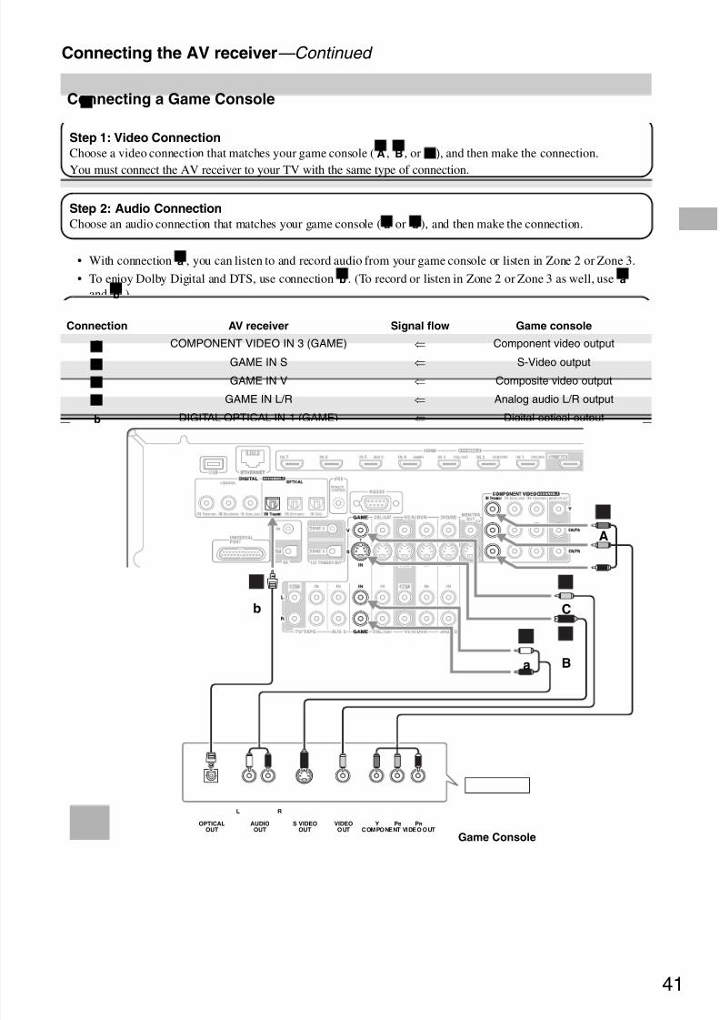
8/8/2019 Manual TX-NR5007 English
http://slidepdf.com/reader/full/manual-tx-nr5007-english 41/16441
Connecting the AV receiver—Continued
• With connection , you can listen to and record audio from your game console or listen in Zone 2 or Zone 3.
• To enjoy Dolby Digital and DTS, use connection . (To record or listen in Zone 2 or Zone 3 as well, useand .)
Connecting a Game Console
Connection AV receiver Signal flow Game console
COMPONENT VIDEO IN 3 (GAME) ⇐ Component video output
GAME IN S ⇐ S-Video output
GAME IN V ⇐ Composite video output
GAME IN L/R ⇐ Analog audio L/R output
DIGITAL OPTICAL IN 1 (GAME) ⇐ Digital optical output
Step 1: Video Connection
Choose a video connection that matches your game console ( , , or ), and then make the connection.You must connect the AV receiver to your TV with the same type of connection.
A B C
Step 2: Audio Connection
Choose an audio connection that matches your game console ( or ), and then make the connection.a b
a
b a
b
A
B
C
a
b
OPTICALOUT
AUDIOOUT
L R
S VIDEOOUT
VIDEOOUT COMPONENT VIDEO OUT
Y PB PR
Ba
A
Cb
Game Console

8/8/2019 Manual TX-NR5007 English
http://slidepdf.com/reader/full/manual-tx-nr5007-english 42/16442
Connecting the AV receiver—Continued
Connecting a Camcorder or Other Device
Connection AV receiver Signal flow Camcorder etc.
AUX1 INPUT VIDEO ⇐ Composite video output
AUX1 INPUT L-AUDIO-R ⇐ Analog audio L/R output
AUX1 INPUT DIGITAL ⇐ Digital optical output
Step 1: Video Connection
Make the connection .A
Step 2: Audio Connection
Choose an audio connection that matches your camcorder ( or ), and then make the connection.a b
A
a
b
AUDIOOUT
VIDEOOUT
L R
VIDEO AUDIOL RAUX1 INPUTAUX1 INPUT
OPTICALOUT
DIGITALAUX1 INPUT
A ba
Camcorder etc.
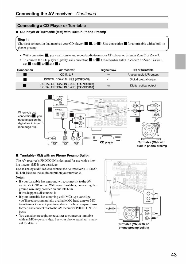
8/8/2019 Manual TX-NR5007 English
http://slidepdf.com/reader/full/manual-tx-nr5007-english 43/16443
Connecting the AV receiver—Continued
CD Player or Turntable (MM) with Built-in Phono Preamp
• With connection , you can listen to and record audio from your CD player or listen in Zone 2 or Zone 3.
• To connect the CD player digitally, use connection or . (To record or listen in Zone 2 or Zone 3 as well,use and , or and .)
Turntable (MM) with no Phono Preamp Built-in
The AV receiver’s PHONO IN is designed for use with a mov-ing magnet (MM) type cartridge.Use an analog audio cable to connect the AV receiver’s PHONOIN L/R jacks to the audio output on your turntable.
Notes:
• If your turntable has a ground wire, connect it to the AV
receiver’s GND screw. With some turntables, connecting theground wire may produce an audible hum.If this happens, disconnect it.
• If your turntable has a moving coil (MC) type cartridge,you’ll need a commercially available MC head amp or MCtransformer. Connect your turntable to the head amp or trans-former, and connect that to the AV receiver’s PHONO IN L/R
jacks.• You can also use a phono equalizer to connect a turntable
with an MC-type cartridge. See your phono equalizer’s man-ual for details.
Connecting a CD Player or Turntable
Connection AV receiver Signal flow CD or turntable
CD IN L/R ⇐ Analog audio L/R output
DIGITAL COAXIAL IN 2 (VCR/DVR) ⇐ Digital coaxial output
DIGITAL OPTICAL IN 2 (CD) (TX-NR3007)DIGITAL OPTICAL IN 3 (CD) (TX-NR5007)
⇐ Digital optical output
Step 1:
Choose a connection that matches your CD player ( , , or ). Use connection for a turntable with a built-inphono preamp.
a b c a
a
b c
a b a c
a
b
c
IN 3(CD)
OPTICAL
IN
L
R
L
R
CD AUDIOOUTPUT
OPTICALOUT
AUDIOOUT
L R
COAXIALOUT
L
R
IN
IN 2
COAXIAL
(VCR/DVR)
CD
a
b
a
c
Turntable (MM) with
built-in phono preamp
CD player
When you use
connection , you
need to assign the
digital audio input
(see page 56).
b
L
R
AUDIO
OUTPUT
Turntable (MM) with no
phono preamp built-in

8/8/2019 Manual TX-NR5007 English
http://slidepdf.com/reader/full/manual-tx-nr5007-english 44/16444
Connecting the AV receiver—Continued
• With connection , you can play and record or listen in Zone 2 or Zone 3.
• To connect the recorder digitally for playback, use connections and , or and .
Connecting a Cassette, CDR, MiniDisc, or DAT Recorder
Step 1:
Choose a connection that matches the recorder ( , or ), and then make the connection.a b c
a
a b a c
Connection AV receiver Signal flow Cassette, CDR, MD, or DAT recorder
TV/TAPE IN L/RTV/TAPE OUT L/R
⇐
⇒
Analog audio L/R outputAnalog audio L/R input
DIGITAL COAXIAL IN 3 (CBL/SAT) ⇐ Digital coaxial output
DIGITAL OPTICAL IN 1 (GAME) (TX-NR3007)DIGITAL OPTICAL IN 2 (TV/TAPE) (TX-NR5007)
⇐ Digital optical output
a
b
c
c
AUDIOIN
L R
L
R
IN
TV/TAPE
AUDIOOUT
L R
L
R
TV/TAPE
COAXIALOUT
OPTICALOUT
COAXIAL
OPTICAL
IN 3
(CBL/SAT)
IN 2
(TV/TAPE)
a
a
b
Cassette, CDR, MD, or
DAT recorder
When you use connection ,
you need to assign the digital
audio input (see page 56).
b
(TX-NR3007) When you use connection , you need
to assign the digital audio input (see page 56).
c

8/8/2019 Manual TX-NR5007 English
http://slidepdf.com/reader/full/manual-tx-nr5007-english 45/16445
Connecting the AV receiver—Continued
If you want to use a more powerful power amplifier and use the AV receiver as a preamp, connect it to the PRE OUT jacks, and connect all speakers and the subwoofer to the power amplifier. You can connect the powered subwoofer witheach jacks respectively. If you use one subwoofer, connect it to PRE OUT: SW1.
Connecting a Power Amplifier
2 3 4 5 6 7 8 91
Power amplifier
Powered subwoofer
See “Connecting Powered Sub-
woofers” on page 19 for more
information.
1. Front left speaker
2. Center speaker3. Front right speaker
4. Surround left speaker
5. Surround right speaker
6. Surround left back speaker
7. Surround right back speaker
8. Front wide/Front high left speaker*
9 Front wide/Front high right speaker*
Note:* Specify “None” for the channel that you don’t want to output in the “Speaker Configuration” (page 95).

8/8/2019 Manual TX-NR5007 English
http://slidepdf.com/reader/full/manual-tx-nr5007-english 46/16446
Connecting the AV receiver—Continued
If Your iPod Supports Video:
Connect your RI Dock’s audio output jacks to theAV receiver’s GAME IN or VCR/DVR IN L/R jacks,and connect its video output jack to the AV receiver’sGAME IN V or VCR/DVR IN V jack. (Onkyo DS-A2 hookup shown below.)
If you have an Onkyo DS-A1 RI Dock
Connect its video output jack to the AV receiver’sGAME IN S or VCR/DVR IN S jack.
If Your iPod Doesn’t Support Video:Connect your RI Dock’s audio output jacks to theAV receiver’s TV/TAPE IN L/R jacks. (Onkyo DS-A2 hookup shown below.)
Note:
When UP-A1 Dock that seated iPod is connected, the power consumption on standby mode slightly increases.
Connecting an RI Dock
Not all iPod models output video. For information
about which iPod models are supported by the RI
Dock, see the RI Dock’s instruction manual.
L
R
IN
GAME
V
GAME
L
R
IN
IN
VCR/DVR
VCR/DVR
V V
IN
Make either
connection.
L
R
IN
TV/TAPE
Connecting a Universal Port Option Series
Notes:
• Enter the appropriate remote control code before using the AV receiver’s remote controller for the first time (seepage 141).
• Connect the RI Dock to the AV receiver with anu cable (see page 47).• Set the RI Dock’s RI MODE switch to “HDD” or “HDD/DOCK”.• Set the AV receiver’s Input Display to “DOCK” (see page 60).• See the RI Dock’s instruction manual for more information.
ex. UP-A1

8/8/2019 Manual TX-NR5007 English
http://slidepdf.com/reader/full/manual-tx-nr5007-english 47/16447
Connecting the AV receiver—Continued
Withu (Remote Interactive), you can use the follow-ing special functions:
Auto Power On/StandbyWhen you start playback on a component connectedviau, if the AV receiver is on Standby, it will auto-matically turn on and select that component as theinput source. Similarly, when the AV receiver is setto Standby, all components connected viau willalso go on Standby.
Direct Change
When playback is started on a component connectedviau, the AV receiver automatically selects thatcomponent as the input source.
Remote Control
You can use the AV receiver’s remote controller tocontrol your otheru-capable Onkyo components,pointing the remote controller at the AV receiver’sremote control sensor instead of the component. Youmust enter the appropriate remote control code first(see page 142).
Notes:
• Use onlyu cables foru connections.u cablesare supplied with Onkyo players (DVD, CD, etc.).
• Some components have twou jacks. You can con-nect either one to the AV receiver. The other jack is forconnecting additionalu-capable components.
• Connect only Onkyo components tou jacks. Con-necting other manufacturer’s components may cause amalfunction.
• Some components may not support allu functions.Refer to the manuals supplied with your other Onkyocomponents.
• While Zone 2 or Zone 3 is on, the Auto PowerOn/Standby and Direct Changeu functions do notwork.
Notes:
• Before connecting the power cord, connect all of your speakers and AV components.
• Turning on the AV receiver may cause a momentarypower surge that might interfere with other electricalequipment on the same circuit. If this is a problem,plug the AV receiver into a different branch circuit.
• Do not use a power cord other than the one suppliedwith the AV receiver. The supplied power cord is
designed exclusively for use with the AV receiver andshould not be used with any other equipment.• Never disconnect the power cord from the AV receiver
while the other end is still plugged into a wall outlet.Doing so may cause an electric shock. Always discon-nect the power cord from the wall outlet first, and thenthe AV receiver.
Connecting Onkyou Components
Step 1:
Make sure that each Onkyo component is connectedto the AV receiver with an analog audio cable (con-
nection in the hookup examples) (see pages 35 to44, 46).
Step 2:
Make theu connection (see illustration right).
Step 3:
If you’re using an MD, CDR, or RI Dock, change theInput Display (see page 60).
a
Connecting the Power Cord
LR
IN
DVD/BD
L
R
IN
CD
L
R
REMOTECONTROL
ANALOG
AUDIO OUT
LR
ANALOG
AUDIO OUT
e.g., CD player
e.g., DVD player
Step 1:
Connect the supplied power cord to the AV receiver’sAC INLET.
Step 2:
Plug the power cord into an AC wall outlet.
To AC wall outlet

8/8/2019 Manual TX-NR5007 English
http://slidepdf.com/reader/full/manual-tx-nr5007-english 48/16448
Turning On the AV receiver
European and Asian models: To completely shut down the AV receiver, set the [POWER] switch to the OFF position( ).
ON/STANDBY ON/STANDBY
POWER
STANDBY
ON
RECEIVER
STANDBY indicator
(North American models) (European and Asian models)
STANDBY indicator
Turning On and Standby
1(European and Asian models)
Set the [POWER] switch to the ON position ( ).
2 On the AV receiver, press the [ON/STANDBY] button.
On the remote controller, press the [RECEIVER] button, followed by the
[ON] button.
The AV receiver comes on, the display lights up, and the STANDBY indicator goes off.Pressing the remote controller’s [ON] button again will turn on any componentsconnected viau.
To turn the AV receiver off, press the [ON/STANDBY] button, or press the remotecontroller’s [STANDBY] button. The AV receiver will enter Standby mode. To preventany loud surprises when you turn on the AV receiver, always turn down the volumebefore you turn it off.
or
Remotecontroller
AV receiver
Smooth Operation in a Few Easy Steps
To ensure smooth operation, here’s a few easy steps to help you configure the AV receiver before you use it for thevery first time. These settings only need to be made once.
Did you connect your TV to an HDMI output or COMPONENT VIDEO MONITOR OUT?
If you did, “Monitor Setup” on page 49. Run MultEQ XT Room Correction and Speaker Setup—this is essential!
See “Audyssey MultEQ® XT Room Correction and Speaker Setup” on page 61.
Have you connected a component to an HDMI input,
component video input, or digital audio input?
If you have, see “HDMI Input Setup” on page 54, “Component VideoInput Setup” on page 55, or “Digital Audio Input Setup” on page 56 respectively.
Have you connected an Onkyo MD recorder, CD recorder,
or RI Dock?
If you have, see “Changing the Input Display” on page 60.
HDMI
OUT IN
TV/TAPE MD recorder, CD recorder,RI Dock

8/8/2019 Manual TX-NR5007 English
http://slidepdf.com/reader/full/manual-tx-nr5007-english 49/16449
First Time Setup
This section explains the settings that you need to make before using the AV receiver for the very first time.
If you connect your TV to HDMI OUT MAIN, “MonitorOut” setting is automatically set so that the onscreen
setup menus are displayed and composite video, S-Video, and component video sources are upconverted* and output.
On the “Monitor Out” settings, you can select whether ornot to have the video sources’ images output through theHDMI output, as well as whether to have the onscreensetup menu output through the HDMI output or throughan analog output.If you connect your TV to the COMPONENT VIDEOMONITOR OUT (not the HDMI output), “Monitor Out”setting is automatically set so that the onscreen setupmenus are displayed and composite video and S-Videosources are upconverted* and output.
Change “Monitor Out” setting manually
Tips:
• The “Monitor Out” setting can also be set using the
[VIDEO] button on the remote controller.• This setting can also be performed by using Onscreen
Setup Menu (see page 52).Notes:
• See page 32 for charts showing how the “MonitorOut” and “Resolution” (see page 52) settings affectthe video signal flow through the AV receiver.
• You can specify the output resolution for the HDMIoutputs and COMPONENT VIDEO MONITOR OUTand have the AV receiver upconvert the pictureresolution as necessary to match the resolutionsupported by your TV (see page 52).
Monitor Setup
IN
OUT
Composite video, S-Video,
component video
Composite video, S-Video,
component video
HDMI
HDMI
IN
OUT
Composite video, S-Video
Composite video, S-Video
Component video
Component video
1 Press the [MONITOR OUT] but-
ton.
The current setting is displayed.
2 Press the [MONITOR OUT] button
repeatedly to select: Analog,
HDMI Main, HDMI Sub, Both,
Both(Main) or Both(Sub)
For details on each item, see step 4 inthe page 52.
MONITOR OUT

8/8/2019 Manual TX-NR5007 English
http://slidepdf.com/reader/full/manual-tx-nr5007-english 50/16450
First Time Setup—Continued
In this Instruction Manual, illustrations from the onscreen menu or explanations referring to the menu will be in thesame language as the Instruction Manual. The default Language setting for the onscreen menu is English. If yourInstruction Manual is in a language other than English, first follow the instructions below to change the Language.
This setting determines the language used for theonscreen setup menus. You can select: English, German,French, Spanish, Italian, Dutch, Swedish, or Chinese.
Note:
This procedure can also be performed on the AV receiverby using its [SETUP] button, arrow buttons, and[ENTER] button.
Selecting the Language used for the
onscreen setup menus
1 Press the [RECEIVER] button,
followed by the [SETUP] button.
The main menu appears onscreen.If the main menu doesn’t appear, makesure the appropriate external input isselected on your TV.
2 Use the Up and Down [q]/[w] but-tons to select “6. Miscella-
neous”, and then press [ENTER].
The “Miscellaneous” menu appears.
SETUP
RECEIVER
qwer
ENTER
1. Input/Output Assign2. Speaker Setup3. Audio Adjust4. Source Setup5. Listening Mode Preset6. Miscellaneous7. Hardware Setup8. Remote Controller Setup9. Lock Setup
Menu
1. Volume Setup2. OSD Setup
6. Miscellaneous
3 Use the Up and Down [q]/[w] but-
tons to select “2. OSD Setup”,and then press [ENTER].
The “OSD Setup” menu appears.
(European and Asian models)
4 Use the Up and Down [q]/[w] but-
tons to select “Language”, and
then use the Left and Right [e]/
[r] buttons to select:
English, Deutsch, Français, Español,
Italiano, Nederlands, Svenska,中文
5 Press the [SETUP] button.
The setup menu closes.
6–2. OSD Setup
Immediate DisplayDisplay PositionTV FormatLanguage
OnBottom
AutoEnglish

8/8/2019 Manual TX-NR5007 English
http://slidepdf.com/reader/full/manual-tx-nr5007-english 51/16451
First Time Setup—Continued
Carry out the settings for the AV receiver by using theOnscreen Setup Menu.
The settings of the AV receiver can be changed using theDisplay.
Onscreen Setup Menus and Display
As each item in the Onscreen Setup Menus is selected,the selected items will be displayed one by one.
Note:
During Audyssey MultEQ® XT Room Correction andSpeaker Setup, messages, etc., that are displayed on theTV screen will appear in the Display.
Using the Onscreen Setup Menus
1 Press the [RECEIVER] button fol-
lowed by the [SETUP] button.
The main menu appears onscreen.If the main menu doesn’t appear, makesure the appropriate external input isselected on your TV.
Tip:
On several functions, the explanationwill be displayed under the screen.
2 Use the Up and Down [q]/[w] but-
tons to select item and then
press [ENTER].
The submenu appears.Press the [SETUP] button to close themenu.Press the [RETURN] button to return tothe previous menu.
SETUP
RECEIVER
qwer
ENTER
1. Input/Output Assign2. Speaker Setup3. Audio Adjust4. Source Setup5. Listening Mode Preset6. Miscellaneous7. Hardware Setup8. Remote Controller Setup9. Lock Setup
Menu
Using the Display to change thesettings
1 Press the [RECEIVER] button fol-lowed by the [SETUP] button.
The main menu item appears on thedisplay.
2 Use the Up and Down [q]/[w] but-
tons to select item and then
press [ENTER].The submenu item appears on thedisplay.Press the [SETUP] button to close themenu.Press the [RETURN] button to return tothe previous menu.
1. Input/Output Assign2. Speaker Setup3. Audio Adjust4. Source Setup5. Listening Mode Preset6. Miscellaneous7. Hardware Setup8. Remote Controller Setup9. Lock Setup
Menu
Onscreen Setup Menus
Display

8/8/2019 Manual TX-NR5007 English
http://slidepdf.com/reader/full/manual-tx-nr5007-english 52/16452
First Time Setup—Continued
If you connect your TV to the HDMI output, set the“Monitor Out” setting so that the onscreen setup menusare displayed and composite video, S-Video, andcomponent video sources are upconverted and output.If you connect your TV to the COMPONENT VIDEOMONITOR OUT, set the “Monitor Out” setting so thatthe onscreen setup menus are displayed and compositevideo and S-Video sources are upconverted and output.You can specify the output resolution for the HDMIoutputs and COMPONENT VIDEO MONITOR OUTand have the AV receiver upconvert the pictureresolution as necessary to match the resolutionsupported by your TV.
Monitor Out Setup
1 Press the [RECEIVER] button,
followed by the [SETUP] button.
The main menu appears onscreen.If the main menu doesn’t appear, makesure the appropriate external input isselected on your TV.
2 Use the Up and Down [q]/[w] but-
tons to select “1. Input/Output
Assign”, and then press
[ENTER].
The “Input/Output Assign” menuappears.
3 Use the Up and Down [q]/[w] but-
tons to select “1. Monitor Out”,
and then press [ENTER].
The “Monitor Out” menu appears.
1. Input/Outpu t Assign
1. Monitor Out2. HDMI Input3. Component Video Input4. Digital Audio Input5. Analog Audio Input
Monitor OutResolutionBrightnessContrastHueSaturation
HDMI MainThrough
0000
1–1. Monitor Out
4 Use the Up and Down [q]/[w] but-
tons to select “Monitor Out”, and
use the Left and Right [e]/[r]
buttons to select:
Analog:
Select this if your TV is connectedto the COMPONENT VIDEOMONITOR OUT, S MONITOROUT, or V MONITOR OUT.
HDMI Main:Select this if your TV is connectedto the HDMI OUT MAIN.
HDMI Sub:Select this if your TV is connectedto the HDMI OUT SUB.
Both:Select this if your TVs are con-nected to the HDMI OUT MAINand HDMI OUT SUB. Video sig-nals are output from both HDMIoutputs at the resolution supportedby both TVs.
Both (Main):Select this if your TVs are con-nected to the HDMI OUT MAINand HDMI OUT SUB. Video sig-nals are output from both HDMIoutputs but HDMI OUT MAIN willbecome a priority; depending on theresolution, video signals may not be
output from HDMI OUT SUB.Both (Sub):
Select this if your TVs are con-nected to the HDMI OUT MAINand HDMI OUT SUB. Video sig-nals are output from both HDMIoutputs but HDMI OUT SUB willbecome a priority; depending on theresolution, video signals may not beoutput from HDMI OUT MAIN.
Notes:• If not connected to the same output
you have selected in the“MonitorOut” setting, the “Monitor Out”setting will be automaticallyswitched to “Analog”.
• When you select other than“Analog”, the onscreen setup menusare output by only the HDMIoutputs. If you’re not using theHDMI output and select settingsby mistake and the menusdisappear, press the [MONITOROUT] button to select “Analog”.
• For Deep Color output, if the“Monitor Out” setting is set to “Both(Main)” or “Both (Sub)”, the numberof bit may be limited due to thecapability of your TV connected to apriority output.

8/8/2019 Manual TX-NR5007 English
http://slidepdf.com/reader/full/manual-tx-nr5007-english 53/16453
First Time Setup—Continued
Notes:
• See page 32 for charts showing how the “MonitorOut” and “Resolution” settings affect the video signalflow through the AV receiver.
• This procedure can also be performed on the AVreceiver by using its [SETUP] button, arrow buttons,and [ENTER] button.
5 Use the Up and Down [q]/[w] but-
tons to select “Resolution”, and
use the Left and Right [e]/[r]
buttons to select:
Through:
Select this to pass video through theAV receiver at the same resolutionand with no conversion.
Auto :
Select this to have the AV receiverautomatically convert video at reso-lutions not supported by your TV.
480p (480p/576p):
Select this for 480p or 576p outputand video conversion as necessary.
720p:
Select this for 720p output andvideo conversion as necessary.
1080i:
Select this for 1080i output andvideo conversion as necessary.
1080p :
Select this for 1080p output andvideo conversion as necessary.
1080p/24 :
Select this for 1080p output at 24
frames per second and video con-version as necessary.
Source:
Output will be according to the res-olution level which was set in the“Picture Adjust” setting (seepage 105).
Tips:
• The “Resolution” setting can also beset using the [VIDEO] button on theremote controller.
• The “Resolution” setting is set
respectively of main, sub, andanalog.
Notes:
• Settings marked with an asterisk ( )are not available when the “MonitorOut” setting is set to “Analog”.
• If the “Monitor Out” setting is set to“Both”, this setting is fixed at“Auto”.
• Depending on the incoming videosignal, video playback may not besmooth or the vertical resolution may
be lowered. In this case select otherthan “1080p/24”.
*
*
*
*
6 Press the [SETUP] button.
The setup menu closes.
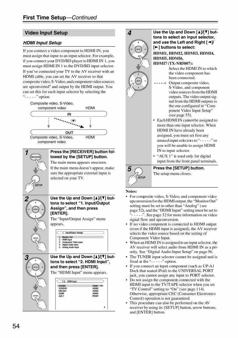
8/8/2019 Manual TX-NR5007 English
http://slidepdf.com/reader/full/manual-tx-nr5007-english 54/16454
First Time Setup—Continued
HDMI Input Setup
If you connect a video component to HDMI IN, youmust assign that input to an input selector. For example,
if you connect your DVD/BD player to HDMI IN 1, youmust assign HDMI IN 1 to the DVD/BD input selector.If you’ve connected your TV to the AV receiver with anHDMI cable, you can set the AV receiver so thatcomposite video, S-Video, and component video sourcesare upconverted* and output by the HDMI output. Youcan set this for each input selector by selecting the“- - - - -” option.
Notes:
• For composite video, S-Video, and component videoupconversion for the HDMI output, the “Monitor Out”setting must be set to other than “Analog” (seepage 52), and the “HDMI Input” setting must be set to“- - - - -”. See page 32 for more information on videosignal flow and upconversion.
• If no video component is connected to HDMI output(even if the HDMI input is assigned), the AV receiverselects the video source based on the setting of
Component Video Input.• When an HDMI IN is assigned to an input selector, the
AV receiver will select audio from HDMI IN as a pri-ority. See “Digital Audio Input Setup” on page 56.
• The TUNER input selector cannot be assigned and isfixed at the “- - - - -” option.
• If you connect an input component (such as UP-A1Dock that seated iPod) to the UNIVERSAL PORT
jack, you cannot assign any input to PORT selector.• Do not assign the component connected with the
HDMI input to the TV/TAPE selector when you set“TV Control” setting to “On” (see page 114).Otherwise, appropriate CEC (Consumer ElectronicsControl) operation is not guaranteed.
• This procedure can also be performed on the AVreceiver by using its [SETUP] button, arrow buttons,and [ENTER] button.
Video Input Setup
1 Press the [RECEIVER] button fol-
lowed by the [SETUP] button.
The main menu appears onscreen.If the main menu doesn’t appear, makesure the appropriate external input is
selected on your TV.
2 Use the Up and Down [q]/[w] but-
tons to select “1. Input/Output
Assign”, and then press
[ENTER].
The “Input/Output Assign” menuappears.
3 Use the Up and Down [q]/[w] but-
tons to select “2. HDMI Input”,
and then press [ENTER].
The “HDMI Input” menu appears.
IN
OUT
Composite video, S-Video,
component video
Composite video, S-Video,
component video
HDMI
HDMI
1. Input/Outpu t Assign
1. Monitor Out2. HDMI Input3. Component Video Input4. Digital Audio Input5. Analog Audio Input
1–2. HDMI Input
DVD/BDVCR/DVRCBL/SATGAME
AUX 1
HDMI1HDMI2HDMI3HDMI4
FRONT
4 Use the Up and Down [q]/[w] but-
tons to select an input selector,
and use the Left and Right [e]/
[r] buttons to select:
HDMI1, HDMI2, HDMI3, HDMI4,
HDMI5, HDMI6,HDMI7 (TX-NR5007):
Select the HDMI IN to whichthe video component hasbeen connected.
- - - - -: Output composite video,S-Video, and componentvideo sources from the HDMIoutputs. The video output sig-nal from the HDMI outputs isthe one configured in “Com-ponent Video Input Setup”(see page 55).
• Each HDMI IN cannot be assigned tomore than one input selector. WhenHDMI IN have already beenassigned, you must set first anyunused input selectors to “- - - - -” oryou will be unable to assign HDMIIN to input selector.
• “AUX 1” is used only for digitalinput from the front panel terminals.
5 Press the [SETUP] button.
The setup menu closes.

8/8/2019 Manual TX-NR5007 English
http://slidepdf.com/reader/full/manual-tx-nr5007-english 55/16455
First Time Setup—Continued
Component Video Input Setup
If you connect to a COMPONENT VIDEO IN, you mustassign it to an input selector. For example, if you connectyour DVD/BD player to COMPONENT VIDEO IN 2,you should assign it to the DVD/BD input selector.
If you’ve connected your TV to the AV receiver with acomponent video cable, you can set the AV receiver sothat composite video and S-Video sources areupconverted* and output by the COMPONENT VIDEOMONITOR OUT*1. You can set this for each inputselector by selecting the “- - - - -” option.
*1 Only when “Monitor Out” setting is set to “Analog”.
Notes:
• For composite video and S-Video upconversion forthe COMPONENT VIDEO MONITOR OUT, the“Monitor Out” setting must be set to “Analog” (seepage 52), and the “Component Video Input” settingmust be set to “- - - - -”. See page 32 for moreinformation on video signal flow and upconversion.
• If not connected to the same output you have selectedin the “Monitor Out” setting, the “Monitor Out”setting will be automatically switched to “Analog”(see page 52).
• If you connect an input component (such as UP-A1
Dock that seated iPod) to the UNIVERSAL PORT jack,
you cannot assign any input to PORT selector.• This procedure can also be performed on the AVreceiver by using its [SETUP] button, arrow buttons,and [ENTER] button.
Input selector Default assignment
DVD/BD IN1
VCR/DVR - - - - -
CBL/SAT IN2
GAME IN3
AUX 1 - - - - -
AUX 2 - - - - -
TV/TAPE - - - - -
TUNER - - - - - (Fixed)
CD - - - - -PHONO - - - - -
PORT - - - - -
1 Press the [RECEIVER] button fol-
lowed by the [SETUP] button.
The main menu appears onscreen.If the main menu doesn’t appear, makesure the appropriate external input isselected on your TV.
2 Use the Up and Down [q]/[w] but-
tons to select “1. Input/Output
Assign”, and then press
[ENTER].
The “Input/Output Assign” menuappears.
IN
OUT
Composite video, S-Video
Composite video, S-Video
Component video
Component video
1. Input/Output Assign
1. Monitor Out2. HDMI Input3. Component Video Input4. Digital Audio Input5. Analog Audio Input
3 Use the Up and Down [q]/[w] but-
tons to select “3. Component
Video Input”, and then press
[ENTER].
The “Component Video Input” menu
appears.
4 Use the Up and Down [q]/[w] but-
tons to select an input selector,
and then use the Left and Right
[e
]/[r
] buttons to select:IN1: Select if the video componentis connected to COMPO-NENT VIDEO IN 1.
IN2: Select if the video componentis connected to COMPO-NENT VIDEO IN 2.
IN3: Select if the video componentis connected to COMPO-NENT VIDEO IN 3.
- - - - -: Select if you are using theHDMI outputs, rather thanthe COMPONENT VIDEO
OUT, for the output fromcomposite video, S-Video,and component videosources.
5 Press the [SETUP] button.
The setup menu closes.
1–3. Component Video Input
IN1- - - - -
IN2IN3
- - - - -
DVD/BDVCR/DVRCBL/SATGAMEAUX 1

8/8/2019 Manual TX-NR5007 English
http://slidepdf.com/reader/full/manual-tx-nr5007-english 56/16456
First Time Setup—Continued
If you connect a component to a digital input jack, youmust assign that jack to an input selector. For example, if you connect your CD player to the OPTICAL IN1 jack,you should assign that jack to the CD input selector. Bydefault, the COAXIAL IN1 jack is assigned to the DVD/ BD input selector, although this can be changed.Here are the default assignments.
Notes:
• Available sampling rate for PCM signals from adigital input (optical and coaxial) is 32/44.1/48/88.2/ 96 kHz/16, 20, 24 bit.
• If you connect an input component (such as UP-A1Dock that seated iPod) to the UNIVERSAL PORT
jack, you cannot assign any input to PORT selector.• This procedure can also be performed on the AV
receiver by using its [SETUP] button, arrow buttons,and [ENTER] button.
Digital Audio Input Setup
Input selectorDefault assignment
(TX-NR3007) (TX-NR5007)
DVD/BD COAX1 COAX1
VCR/DVR COAX2 COAX2
CBL/SAT COAX3 COAX3
GAME OPT1 OPT1
AUX 1 FRONT (Fixed) FRONT (Fixed)
AUX 2 - - - - - - - - - -
TV/TAPE - - - - - OPT2TUNER - - - - - (Fixed) - - - - - (Fixed)
CD OPT2 OPT3
PHONO - - - - - - - - - -
PORT - - - - - - - - - -
1 Press the [RECEIVER] button fol-
lowed by the [SETUP] button.
The main menu appears onscreen.If the main menu doesn’t appear, makesure the appropriate external input isselected on your TV.
2 Use the Up and Down [q]/[w] but-
tons to select “1. Input/Output
Assign”, and then press
[ENTER].
The “Input/Output Assign” menuappears.
3 Use the Up and Down [q]/[w] but-
tons to select “4. Digital Audio
Input”, and then press [ENTER].
The “Digital Audio Input” menuappears.
1. Input/Outpu t Assign
1. Monitor Out2. HDMI Input
3. Component Video Input4. Digital Audio Input5. Analog Audio Input
1–4. Digital Audio Input
DVD/BDVCR/DVR
CBL/SATGAMEAUX 1
COAX1COAX2
COAX3OPT1
FRONT
4 Use the Up and Down [q]/[w] but-
tons to select an input selector,
and use the Left and Right [e]/
[r] buttons to select “COAX1”,
“COAX2”, “COAX3”, “OPT1”,
“OPT2”, “OPT3” (TX-NR5007), or“- - - - - (analog)”.
• When an HDMI IN is assigned to aninput selector in “HDMI InputSetup” on page 54, the AV receiverwill select audio from HDMI IN as apriority.
• Press the [ENTER] button when youdo not use the signal of audio fromthe HDMI IN. The “ ” mark is dis-played like “COAX1 ”.
• “AUX 1” is used only for digitalinput from the front panel terminals.
Examples:
If you connect your DVD player to theOPTICAL IN 1 jack, set “DVD/BD” to“OPT1”.If you want to listen to audio from thecomponent connected to the OPTICALIN 2 jack when the VCR/DVR inputselector is selected, set “VCR/DVR” to“OPT2”.If you want to listen to audio from the
component connected to theCOAXIAL IN 1 jack when the CBL/ SAT input selector is selected, set“CBL/SAT” to “COAX1”.For input selectors that you don’t wantto assign a digital input jack, set to“- - - - - (analog)”.
5 Press the [SETUP] button.
The setup menu closes.
**
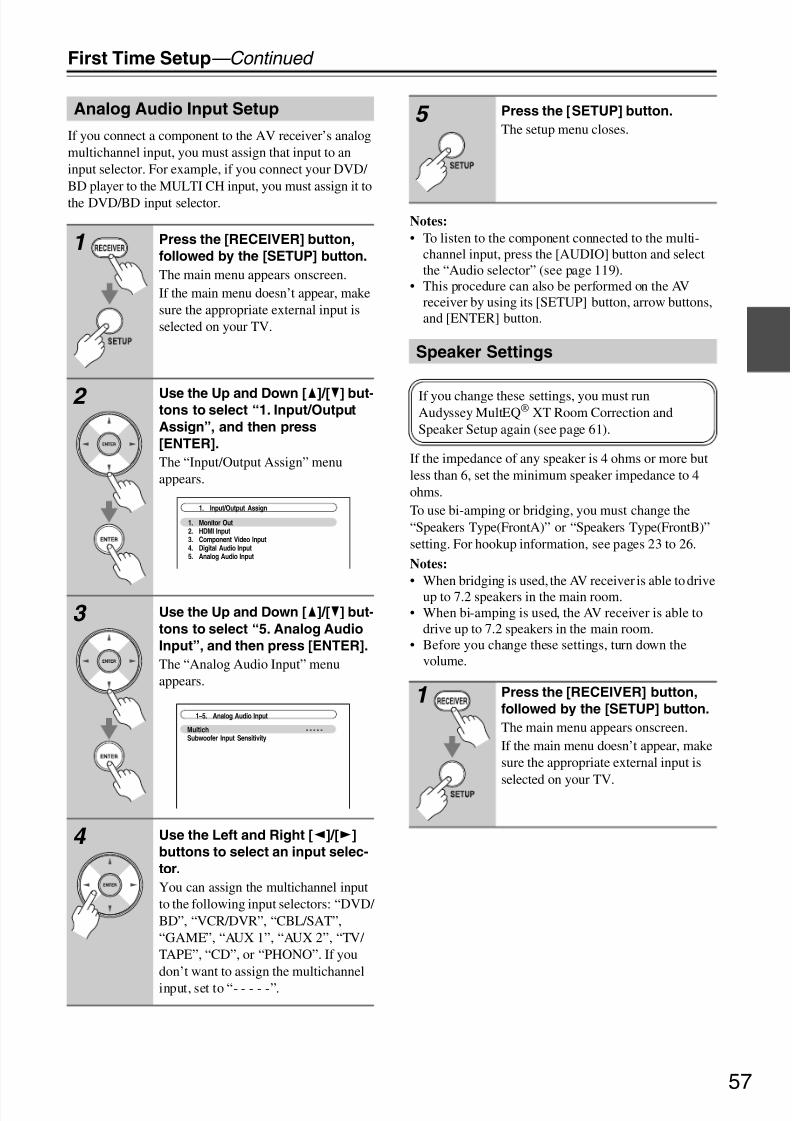
8/8/2019 Manual TX-NR5007 English
http://slidepdf.com/reader/full/manual-tx-nr5007-english 57/16457
First Time Setup—Continued
If you connect a component to the AV receiver’s analogmultichannel input, you must assign that input to aninput selector. For example, if you connect your DVD/ BD player to the MULTI CH input, you must assign it tothe DVD/BD input selector.
Notes:
• To listen to the component connected to the multi-channel input, press the [AUDIO] button and selectthe “Audio selector” (see page 119).
• This procedure can also be performed on the AVreceiver by using its [SETUP] button, arrow buttons,and [ENTER] button.
If the impedance of any speaker is 4 ohms or more butless than 6, set the minimum speaker impedance to 4ohms.To use bi-amping or bridging, you must change the“Speakers Type(FrontA)” or “Speakers Type(FrontB)”setting. For hookup information, see pages 23 to 26.
Notes:
• When bridging is used, the AV receiver is able to driveup to 7.2 speakers in the main room.
• When bi-amping is used, the AV receiver is able todrive up to 7.2 speakers in the main room.
• Before you change these settings, turn down thevolume.
Analog Audio Input Setup
1 Press the [RECEIVER] button,
followed by the [SETUP] button.
The main menu appears onscreen.If the main menu doesn’t appear, makesure the appropriate external input isselected on your TV.
2 Use the Up and Down [q]/[w] but-tons to select “1. Input/Output
Assign”, and then press
[ENTER].
The “Input/Output Assign” menuappears.
3 Use the Up and Down [q]/[w] but-
tons to select “5. Analog Audio
Input”, and then press [ENTER].
The “Analog Audio Input” menuappears.
4 Use the Left and Right [e]/[r]
buttons to select an input selec-
tor.
You can assign the multichannel inputto the following input selectors: “DVD/ BD”, “VCR/DVR”, “CBL/SAT”,“GAME”, “AUX 1”, “AUX 2”, “TV/ TAPE”, “CD”, or “PHONO”. If youdon’t want to assign the multichannelinput, set to “- - - - -”.
1. Input/Output Assign
1. Monitor Out2. HDMI Input3. Component Video Input4. Digital Audio Input5. Analog Audio Input
MultichSubwoofer Input Sensitivity
- - - - -
1–5. Analog Audio Input
5 Press the [SETUP] button.
The setup menu closes.
Speaker Settings
1 Press the [RECEIVER] button,
followed by the [SETUP] button.
The main menu appears onscreen.If the main menu doesn’t appear, makesure the appropriate external input is
selected on your TV.
If you change these settings, you must runAudyssey MultEQ® XT Room Correction andSpeaker Setup again (see page 61).
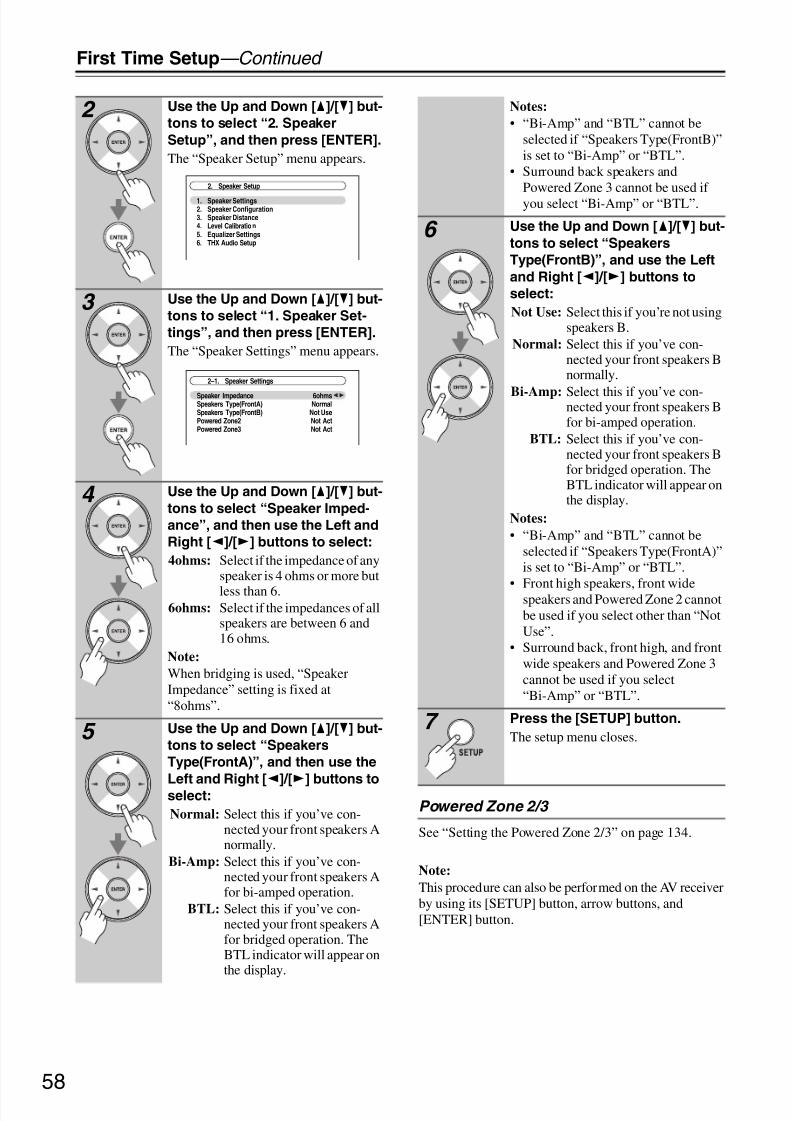
8/8/2019 Manual TX-NR5007 English
http://slidepdf.com/reader/full/manual-tx-nr5007-english 58/16458
First Time Setup—Continued
Powered Zone 2/3
See “Setting the Powered Zone 2/3” on page 134.
Note:
This procedure can also be performed on the AV receiverby using its [SETUP] button, arrow buttons, and[ENTER] button.
2 Use the Up and Down [q]/[w] but-
tons to select “2. Speaker
Setup”, and then press [ENTER].
The “Speaker Setup” menu appears.
3 Use the Up and Down [q]/[w] but-
tons to select “1. Speaker Set-
tings”, and then press [ENTER].
The “Speaker Settings” menu appears.
4 Use the Up and Down [q]/[w] but-
tons to select “Speaker Imped-
ance”, and then use the Left and
Right [e]/[r] buttons to select:
4ohms: Select if the impedance of anyspeaker is 4 ohms or more but
less than 6.6ohms: Select if the impedances of all
speakers are between 6 and16 ohms.
Note:
When bridging is used, “SpeakerImpedance” setting is fixed at“8ohms”.
5 Use the Up and Down [q]/[w] but-
tons to select “Speakers
Type(FrontA)”, and then use the
Left and Right [e
]/[r
] buttons toselect:
Normal: Select this if you’ve con-nected your front speakers Anormally.
Bi-Amp: Select this if you’ve con-nected your front speakers Afor bi-amped operation.
BTL: Select this if you’ve con-nected your front speakers Afor bridged operation. TheBTL indicator will appear onthe display.
2. Speaker Setup
1. Speaker Settings2. Speaker Configuration3. Speaker Distance4. Level Calibratio n5. Equalizer Settings6. THX Audio Setup
2–1. Speaker Settings
Speaker ImpedanceSpeakers Type(FrontA)Speakers Type(FrontB)Powered Zone2Powered Zone3
6ohmsNormal
Not UseNot ActNot Act
Notes:
• “Bi-Amp” and “BTL” cannot beselected if “Speakers Type(FrontB)”is set to “Bi-Amp” or “BTL”.
• Surround back speakers andPowered Zone 3 cannot be used if you select “Bi-Amp” or “BTL”.
6 Use the Up and Down [q]/[w] but-
tons to select “Speakers
Type(FrontB)”, and use the Left
and Right [e]/[r] buttons to
select:
Not Use: Select this if you’re not usingspeakers B.
Normal: Select this if you’ve con-nected your front speakers Bnormally.
Bi-Amp: Select this if you’ve con-nected your front speakers Bfor bi-amped operation.
BTL: Select this if you’ve con-nected your front speakers Bfor bridged operation. TheBTL indicator will appear onthe display.
Notes:
• “Bi-Amp” and “BTL” cannot beselected if “Speakers Type(FrontA)”is set to “Bi-Amp” or “BTL”.
• Front high speakers, front widespeakers and Powered Zone 2 cannotbe used if you select other than “NotUse”.
• Surround back, front high, and frontwide speakers and Powered Zone 3cannot be used if you select“Bi-Amp” or “BTL”.
7 Press the [SETUP] button.
The setup menu closes.

8/8/2019 Manual TX-NR5007 English
http://slidepdf.com/reader/full/manual-tx-nr5007-english 59/16459
First Time Setup—Continued
For the onscreen setup menus to display properly, youmust specify the TV system used in your area.
Note:
This procedure can also be performed on the AV receiverby using its [SETUP] button, arrow buttons, and[ENTER] button.
For FM/AM tuning to work properly, you must specifythe FM/AM frequency step used in your area. Note thatwhen this setting is changed, all radio presets aredeleted.
TV Format Setup (European andAsian models)
1 Press the [RECEIVER] button fol-
lowed by the [SETUP] button.
The main menu appears onscreen.If the main menu doesn’t appear, makesure the appropriate external input isselected on your TV.
2 Use the Up and Down [q
]/[w
] but-tons to select “6. Miscella-
neous”, and then press [ENTER].
The “Miscellaneous” menu appears.
3 Use the Up and Down [q]/[w] but-tons to select “2. OSD Setup”,
and then press [ENTER].
The “OSD Setup” menu appears.
4 Use the Up and Down [q]/[w] but-
tons to select “TV Format”, and
then use the Left and Right
[e]/[r] buttons to select:
Auto: Select this to automaticallydetect the TV system from thevideo input signals.
NTSC: Select if the TV system inyour area is NTSC.
PAL: Select if the TV system inyour area is PAL.
1. Volume Setup2. OSD Setup
6. Miscellaneous
6–2. OSD Setup
Immediate DisplayDisplay PositionTV FormatLanguage
OnBottom
AutoEnglish
5 When you’ve finished, press the
[SETUP] button.
The setup menu closes.
FM/AM Frequency Step Setup
1 Press the [RECEIVER] button,
followed by the [SETUP] button.
The main menu appears onscreen.If the main menu doesn’t appear, makesure the appropriate external input isselected on your TV.
2 Use the Up and Down [q]/[w] but-
tons to select “7. Hardware
Setup”, and then press [ENTER].
The “Hardware Setup” menu appears.
7. Hardware Setup
1. Remote ID2. Multi Zone3. Tuner4. HDMI5. Network 6. Firmware Update
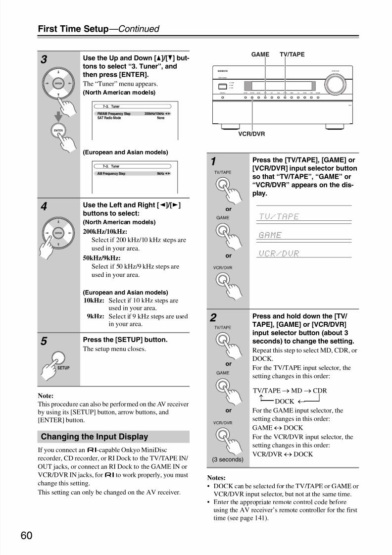
8/8/2019 Manual TX-NR5007 English
http://slidepdf.com/reader/full/manual-tx-nr5007-english 60/16460
First Time Setup—Continued
Note:
This procedure can also be performed on the AV receiverby using its [SETUP] button, arrow buttons, and[ENTER] button.
If you connect anu-capable Onkyo MiniDiscrecorder, CD recorder, or RI Dock to the TV/TAPE IN/ OUT jacks, or connect an RI Dock to the GAME IN orVCR/DVR IN jacks, foru to work properly, you must
change this setting.This setting can only be changed on the AV receiver.
Notes:
• DOCK can be selected for the TV/TAPE or GAME orVCR/DVR input selector, but not at the same time.
• Enter the appropriate remote control code beforeusing the AV receiver’s remote controller for the firsttime (see page 141).
3 Use the Up and Down [q]/[w] but-
tons to select “3. Tuner”, and
then press [ENTER].
The “Tuner” menu appears.(North American models)
(European and Asian models)
4 Use the Left and Right [e]/[r]
buttons to select:
(North American models)
200kHz/10kHz:
Select if 200 kHz/10 kHz steps areused in your area.
50kHz/9kHz:
Select if 50 kHz/9 kHz steps areused in your area.
(European and Asian models)10kHz: Select if 10 kHz steps are
used in your area.9kHz: Select if 9 kHz steps are used
in your area.
5 Press the [SETUP] button.
The setup menu closes.
Changing the Input Display
7–3. Tuner
FM/AM Frequency StepSAT Radio Mode
200kHz/10kHzNone
AM Frequency Step 9kHz
7–3. Tuner1 Press the [TV/TAPE], [GAME] or
[VCR/DVR] input selector button
so that “TV/TAPE”, “GAME” or
“VCR/DVR” appears on the dis-
play.
2 Press and hold down the [TV/
TAPE], [GAME] or [VCR/DVR]
input selector button (about 3
seconds) to change the setting.
Repeat this step to select MD, CDR, orDOCK.For the TV/TAPE input selector, thesetting changes in this order:
For the GAME input selector, thesetting changes in this order:GAME↔ DOCKFor the VCR/DVR input selector, thesetting changes in this order:VCR/DVR↔ DOCK
GAME TV/TAPE
VCR/DVR
or
or
or
or
(3 seconds)
TV/TAPE→MD→ CDRDOCK →
→

8/8/2019 Manual TX-NR5007 English
http://slidepdf.com/reader/full/manual-tx-nr5007-english 61/16461
First Time Setup—Continued
With the supplied calibrated microphone,Audyssey MultEQ XT automatically determines the
number of speakers connected, their size for purposes of bass management, optimum crossover frequencies to thesubwoofer (if present), and distances from the primarylistening position.Audyssey MultEQ XT then removes the distortioncaused by room acoustics by capturing room acousticalproblems over the listening area in both the frequencyand time domain. The result is clear, well-balancedsound for everyone. Enabling Audyssey MultEQ XTallows you to also use Audyssey Dynamic EQ™, whichmaintains the proper octave-to-octave balance at anyvolume level (see page 102).
Before using this function, connect and position all of your speakers.If Audyssey Dynamic EQ is set to “On”,Audyssey Dynamic Volume™ becomes available.
Measurement Positions
To create a listening environment in your home theaterthat all listeners will enjoy, Audyssey MultEQ XT takesmeasurements at up to eight positions within thelistening area.
First measurement point
Also referred to as the Main Listening Position thisrefers to the most central position where one wouldnormally sit within the listening environment.MultEQ XT uses the measurements from this posi-tion to calculate speaker distance, level, polarity, andthe optimum crossover value for the subwoofer.
Second−eighth measurement positions
These are the other listening positions (i.e., theplaces where the other listeners will sit). You can
measure up to eight positions.The following examples show some typical home theaterseating arrangements. Choose the one that best matchesyours, and position the microphone accordingly whenprompted.
Audyssey MultEQ ® XT RoomCorrection and Speaker Setup
About Audyssey Dynamic EQ
Audyssey Dynamic EQ solves the problem of deterio-rating sound quality as volume is decreased by takinginto account human perception and room acoustics.Dynamic EQ selects the correct frequency responseand surround levels moment-by-moment at any user-selected volume setting. The result is bass response,
tonal balance, and surround impression that remainconstant despite changes in volume. Dynamic EQcombines information from incoming source levelswith actual output sound levels in the room, a prereq-uisite for delivering a loudness correction solution.Audyssey Dynamic EQ works in tandem withAudyssey MultEQ XT to provide well-balancedsound for every listener at any volume level.
About Audyssey Dynamic Volume
Audyssey Dynamic Volume solves the problem of large variations in volume level between television
programs, commercials, and between the soft and loudpassages of movies. Dynamic Volume looks at the pre-ferred volume setting by the user and then monitorshow the volume of program material is being per-ceived by listeners in real time to decide whether anadjustment is needed. Whenever necessary, DynamicVolume makes the necessary rapid or gradual adjust-ments to maintain the desired playback volume levelwhile optimizing the dynamic range.Audyssey Dynamic EQ is integrated into DynamicVolume so that as the playback volume is adjustedautomatically, the perceived bass response, tonal bal-
ance, surround impression, and dialog clarity remainthe same whether watching movies, flipping betweentelevision channels, or changing from stereo to sur-round sound content.
–
TV TV TV
TV TV TV
TV TV TV
: listening area : listening position
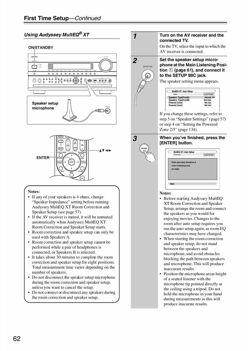
8/8/2019 Manual TX-NR5007 English
http://slidepdf.com/reader/full/manual-tx-nr5007-english 62/16462
First Time Setup—Continued
Using Audyssey MultEQ ® XT
ENTER
ON/STANDBY
qwer
Speaker setup
microphone
Notes:
• If any of your speakers is 4 ohms, change“Speaker Impedance” setting before runningAudyssey MultEQ XT Room Correction andSpeaker Setup (see page 57).
• If the AV receiver is muted, it will be unmutedautomatically when Audyssey MultEQ XTRoom Correction and Speaker Setup starts.
• Room correction and speaker setup can only beused with Speakers A.
• Room correction and speaker setup cannot be
performed while a pair of headphones isconnected, or Speakers B is selected.
• It takes about 30 minutes to complete the roomcorrection and speaker setup for eight positions.Total measurement time varies depending on thenumber of speakers.
• Do not disconnect the speaker setup microphoneduring the room correction and speaker setup,unless you want to cancel the setup.
• Do not connect or disconnect any speakers duringthe room correction and speaker setup.
1 Turn on the AV receiver and the
connected TV.
On the TV, select the input to which theAV receiver is connected.
2 Set the speaker setup micro-phone at the Main Listening Posi-
tiona (page 61), and connect it
to the SETUP MIC jack.
The speaker setting menu appears.
If you change these settings, refer tostep 5 on “Speaker Settings” (page 57)
or step 4 on “Setting the PoweredZone 2/3” (page 134).
3 When you’ve finished, press the
[ENTER] button.
Notes:
• Before starting Audyssey MultEQXT Room Correction and SpeakerSetup, arrange the room and connectthe speakers as you would forenjoying movies. Changes to theroom after auto setup requires yourun the auto setup again, as room EQcharacteristics may have changed.
• When starting the room correctionand speaker setup, do not standbetween the speakers andmicrophone, and avoid obstaclesblocking the path between speakersand microphone. This will produceinaccurate results.
• Position the microphone at ear heightof a seated listener with themicrophone tip pointed directly atthe ceiling using a tripod. Do nothold the microphone in your handduring measurements as this willproduce inacurate results.
MultEQ XT: Auto Setup
Speakers Type(FrontA)Speakers Type(FrontB)Powered Zone2Powered Zone3
NormalNot UseNot ActNot Act
MultEQ XT: Auto Setup
Please place setup microphone at
center of listening area at
ear height.
Next

8/8/2019 Manual TX-NR5007 English
http://slidepdf.com/reader/full/manual-tx-nr5007-english 63/16463
First Time Setup—Continued
• Make the room as quiet as possible.Background noise can disrupt theroom measurements. Closewindows, silence cell phones,televisions, radios, air conditioners,fluorescent lights, home appliances,light dimmers, or other devices.
• Cell phones should be turned off orplaced away from all audioelectronics during the measurementprocess as Radio FrequencyInterference (RFI) may causemeasurement disruptions (even if thecell phone is not in use).
4 Press [ENTER].
The room correction and speaker setupstarts.
Test tones are played through eachspeaker as Audyssey MultEQ® XTRoom Correction and Speaker Setup
runs. This process takes a few minutes.Please refrain from talking duringmeasurements and do not standbetween speakers and the microphone.
5 The following screen appears.
Place the setup microphone at
the next position (page 61), and
then press [ENTER].
Audyssey MultEQ XT performs moremeasurements. This takes a fewminutes.
MultEQ XT: Auto Setup
Do not unplug setup microphone.
Please keep quiet.
Now measuring. . .
MultEQ XT: Auto Setup
Next
Please place setup microphone at 2nd position at
ear height.
MultEQ XT: Auto Setup
Do not unplug setup microphone.
Please keep quiet.
Now measuring. . .
6 When prompted, place the setup
microphone at the next position,
and repeat step 5.
7 After the 3rd to the 8th measure-
ment, the following screen
appears.
Use the Up and Down [q]/[w] but-
tons to select an option, and then
press [ENTER].Next:
Select “Next” to begin measuringthe next measurement position.After the 8th measurement has beentaken, the procedure automaticallyproceeds to step 8.
Finish(Calculate):
Select this if you don’t want tomeasure any more listening posi-tions and are ready to calculate the
results, then go to step 8.
8 When the measurements are
complete, the following screen
appears.
MultEQ XT: Auto Setup
NextFinish(Calculate)
Please select [Next], when measuring next position,
and select [Finish], when ending.
MultEQ XT: Auto Setup
Calculating...

8/8/2019 Manual TX-NR5007 English
http://slidepdf.com/reader/full/manual-tx-nr5007-english 64/16464
First Time Setup—Continued
Notes:
• When the room correction and speaker setup iscomplete, the “Equalizer Settings” (page 98) will beset to “Audyssey” and “Dynamic EQ” (page 102) willbe set to “On”.
• You can cancel the Room Correction and Speaker
Setup at any point in this procedure simply bydisconnecting the setup microphone.
Error Messages
While the room correction and speaker setup is inprogress, one of the following error messages mayappear:
Ambient noise is too high.
This message appears if the background noise is tooloud and the measurements cannot be performedproperly.
Remove the source of the noise and try again.Retry: Return to the measured point immediately
before and start set up again.Cancel: Cancel the room correction and speaker setup.
Speaker Detect Error
This message appears if a speaker is not detected. “Yes”means that a speaker was detected. “No” means that nospeaker was detected.
Tip:
See “Speaker Configuration” (page 19) for appropriatesettings.
The front speaker has not been detected.
9 When the calculations are com-
plete, the following screen
appears.
Use the Up and Down [q]/[w] but-
tons to select an option, and then
press [ENTER].
The options are:
Save:Save the calculated settings and exitthe room correction and speakersetup.
Cancel:
Cancel the room correction andspeaker setup.
Note:
You can view the calculated settings forthe speaker configuration, speaker dis-tances, and speaker levels by using theLeft and Right [e]/[r] buttons.
10 If you selected “Save”, the results aresaved, and the following screenappears.
11 Disconnect the speaker setup
microphone.
Subwoofer NoFront Full BandCenter 40HzSurround 120HzFront Wide Full BandFront High Full BandSurr Back 150HzSurr Back Ch 2ch
--
Review SP Configuration--
MultEQ XT: Auto Setup
SaveCancel
MultEQ XT: Auto Setup
Saving...
MultEQ XT: Auto Setup
Please, unplug setup microphone.
MultEQ XT: Auto Setup
RetryCancel
Ambient noise is too high.
FL : NoSL : -- -FWL : ---FHL : ---SBL : ---C : ---
FR : - --SR : ---FWR : ---FHR : ---SBR : ---SW1 : ---SW2 : ---
MultEQ XT: Auto Setup
RetryCancel
Speaker Detect Error

8/8/2019 Manual TX-NR5007 English
http://slidepdf.com/reader/full/manual-tx-nr5007-english 65/16465
First Time Setup—Continued
One of the front speakers has not been detected.
One of the front wide speakers has not beendetected.
One of the front high speakers has not been detected.
One of the surround speakers has not been detected.
The surround back speakers have been detected butthe surround speakers haven’t.
The front high speakers have been detected but thesurround speakers haven’t.
The front wide speakers have been detected but thesurround speakers haven’t.
The right surround back speaker has been detectedbut the left surround back speaker hasn’t.
The left surround back speaker has been detected but
the surround speaker hasn’t.
Subwoofer 2 has been detected but Subwoofer 1 hasnot.
MultEQ XT: Auto Setup
RetryCancel
Speaker Detect Error
FL : YesSL : -- -FWL : YesFHL : YesSBL : ---C : Yes
FR : NoSR : ---FWR : YesFHR : YesSBR : ---SW1 : ---
SW2 : ---
FL : YesSL : -- -FWL : YesFHL : YesSBL : ---C : Yes
FR : ---SR : ---FWR : NoFHR : YesSBR : ---SW1 : ---SW2 : ---
MultEQ XT: Auto Setup
RetryCancel
Speaker Detect Error
FL : YesSL : -- -FWL : YesFHL : YesSBL : ---C : Yes
FR : ---SR : ---FWR : ---FHR : NoSBR : ---SW1 : ---SW2 : ---
MultEQ XT: Auto Setup
RetryCancel
Speaker Detect Error
FL : YesSL : NoFWL : YesFHL : YesSBL : YesC : Yes
FR : YesSR : YesFWR : YesFHR : YesSBR : YesSW1 : ---SW2 : ---
MultEQ XT: Auto Setup
RetryCancel
Speaker Detect Error
MultEQ XT: Auto Setup
RetryCancel
Speaker Detect Error
FL : YesSL : -- -FWL : NoFHL : NoSBL : ---C : Yes
FR : YesSR : NoFWR : NoFHR : NoSBR : YesSW1 : ---SW2 : ---
MultEQ XT: Auto Setup
RetryCancel
Speaker Detect Error
FL : YesSL : ---FWL : NoFHL : YesSBL : ---C : Yes
FR : YesSR : NoFWR : NoFHR : YesSBR : ---SW1 : ---
SW2 : ---
MultEQ XT: Auto Setup
RetryCancel
Speaker Detect Error
FL : YesSL : ---FWL : YesFHL : NoSBL : ---C : Yes
FR : YesSR : NoFWR : YesFHR : NoSBR : ---SW1 : ---SW2 : ---
FL : YesSL : ---FWL : YesFHL : YesSBL : NoC : Yes
FR : YesSR : YesFWR : YesFHR : YesSBR : YesSW1 : ---SW2 : ---
MultEQ XT: Auto Setup
RetryCancel
Speaker Detect Error
FL : YesSL : ---FWL : NoFHL : NoSBL : YesC : Yes
FR : YesSR : NoFWR : NoFHR : NoSBR : NoSW1 : ---SW2 : ---
MultEQ XT: Auto Setup
RetryCancel
Speaker Detect Error
FL : YesSL : YesFWL : YesFHL : YesSBL : YesC : Yes
FR : YesSR : YesFWR : YesFHR : YesSBR : YesSW1 : NoSW2 : Yes
MultEQ XT: Auto Setup
RetryCancel
Speaker Detect Error

8/8/2019 Manual TX-NR5007 English
http://slidepdf.com/reader/full/manual-tx-nr5007-english 66/16466
First Time Setup—Continued
The speaker type detected does not match what wasexpected. The speaker may be incorrect type or bro-ken. Please check that it is the correct speaker type.
Speaker Matching Error!
The number of speakers detected on the second mea-surement and later was different to the numberdetected on the first measurement.
Make sure speakers that could not be detected areconnected properly.Retry: Return to step 2 and try again.
Cancel: Cancel the room correction and speaker setup.
Writing Error!
This message appears if saving fails.
Try saving again. If this message appears after 2 or 3
attempts, the AV receiver is probably malfunctioning.Contact your Onkyo dealer.Retry: Return to step 2 and try again.
Cancel: Cancel the room correction and speaker setup.
Changing the Speaker Settings Manually
If you wish to make changes to the settings found duringthe room correction and speaker setup, follow thedirections on pages 95 to 98.
Notes:
• Please note that THX recommends any THX mainspeakers be set to “80Hz(THX)”. If you set up yourspeakers using Audyssey MultEQ XT RoomCorrection and Speaker Setup, please make suremanually that any THX speakers are set to 80 Hz(THX) crossover (see page 95).
• Sometimes due to the electrical complexities of subwoofers and the interaction with the room, THXrecommends setting the level and the distance of thesubwoofer manually.
• Sometimes due to interaction with the room, you maynotice irregular results when setting the level and/or
distance of the main speakers. If this happens, THXrecommends setting them manually.
Using Powered Subwoofers
If you’re using powered subwoofers that output verylow-frequency sound at a low volume level, it may not bedetected by Audyssey MultEQ® XT Room Correctionand Speaker Setup.If the “Subwoofer” appears on the “Review SPConfiguration” screen as “No”, increase the subwoofer’svolume to the half-way point, set it to its highestcrossover frequency, and then try runningAudyssey MultEQ XT Room Correction and SpeakerSetup again. Note that if the volume is set too high andthe sound distorts, detection issues may occur, so use anappropriate volume level. If the subwoofer has a low-pass filter switch, set it to Off or Direct. Refer to yoursubwoofer’s instruction manual for details.
FL : ErrorSL : YesFWL : ---FHL : ---SBL : YesC : Yes
FR : YesSR : YesFWR : ---FHR : ---SBR : YesSW1 : Yes
SW2 : Yes
MultEQ XT: Auto Setup
RetryCancel
Speaker Detect Error
MultEQ XT: Auto Setup
RetryCancel
Speaker Matching Error!
MultEQ XT: Auto Setup
RetryCancel
Writing Error!

8/8/2019 Manual TX-NR5007 English
http://slidepdf.com/reader/full/manual-tx-nr5007-english 67/16467
Basic Operations
This section explains how to select the input source (i.e., the AV component that you want to listen to or watch).
Selecting the Input Source
1 Use the AV receiver’s input selector buttons to select the input
source.
To select the input source with the remote controller, press the
[RECEIVER] button, and then press the INPUT SELECTOR but-
tons.
2 Start playback on the source component.
When you select DVD or another video component, on your TV, you’ll needto select the video input that’s connected to the AV receiver’s HDMI outputs,COMPONENT VIDEO MONITOR OUT or MONITOR OUT.On some DVD players, you may need to turn on the digital audio output.
3 To adjust the volume, use the MASTER VOLUME control, or the
remote controller’s VOL [q]/[w] button.
The volume can be set to –Q dB, –81.5 dB through +18.0 dB (relative dis-play).The AV receiver is designed for home theater enjoyment. It has a wide volumerange, allowing precise adjustment.The volume level can also be displayed as an absolute value. See “VolumeSetup” on page 110.
4 Select a listening mode and enjoy!
See “Using the Listening Modes” on page 81.
MASTER VOLUME
VOLq / w
INPUT
SELECTOR
RECEIVER
Input selector buttons
Remotecontroller
AV receiver
or
or
AV receiver Remotecontroller

8/8/2019 Manual TX-NR5007 English
http://slidepdf.com/reader/full/manual-tx-nr5007-english 68/16468
Basic Operations—Continued
You can adjust the bass and treble for the front speakers,except when the Direct, Pure Audio or THX listeningmode is selected.
Bass
You can boost or cut low-frequency sounds output by thefront speakers from –10 dB to +10 dB in 2 dB steps.
Treble
You can boost or cut high-frequency sounds output bythe front speakers from –10 dB to +10 dB in 2 dB steps.
Notes:
• This setting is not available when the multichannelAnalog input is selected.
• The tone can be adjusted for Speakers A and SpeakersB individually.
• To bypass the bass and treble tone circuits, select the
Direct, Pure Audio or THX listening mode.
You can display various information about the currentinput source as follows.
Note:
This procedure can also be performed on the AV receiverby using its [DISPLAY] button.
The following information can typically be displayed forinput sources.
* If the input signal is analog, no format information is displayed.If the input signal is PCM, the sampling frequency is displayed.If the input signal is digital but not PCM, the signal format andthe number of channels is displayed. For some digital input sig-nals, including multichannel PCM, the signal format, number of channels, and sampling frequency is displayed.Information is displayed for about three seconds, then the previ-ously displayed information reappears.
Adjusting the Bass & Treble
1AV receiver
Press the [TONE] button repeat-
edly to select either “Bass” or
“Treble” for each speaker or sub-
woofer.
2 AV receiver
Use the Up [r] and Down [e]
buttons to adjust.
Tip:
This procedure can also be performedon the remote controller by using[AUDIO] button (see page 117).
TONE,e,r DIMMER
DISPLAY
DISPLAY
DIMMER
MUTING
SLEEP
SP LAYOUT
Press
[RECEIVER]first.
Displaying Source Information
Remotecontroller
Press the [RECEIVER] button,
and then press the [DISPLAY]
button repeatedly to cycle
through the available informa-
tion.
Sampling
frequency
Input source
Signal format*
Listening
mode
Input Signal
Resolution
Output
Resolution

8/8/2019 Manual TX-NR5007 English
http://slidepdf.com/reader/full/manual-tx-nr5007-english 69/16469
Basic Operations—Continued
You can adjust the brightness of the AV receiver’s dis-play.
You can temporarily mute the output of the AV receiver.
Tip:
You can specify how much the output is muted with the“Muting Level” setting (page 110).
With the sleep timer, you can set the AV receiver to turnoff automatically after a specified period.
If you need to cancel the sleep timer, press the [SLEEP]button repeatedly until the SLEEP indicator disappears.
To check the time remaining until the AV receiver sleeps,press the [SLEEP] button. Note that if you press the[SLEEP] button while the sleep time is being displayed,you’ll shorten the sleep time by 10 minutes.
Setting the Display Brightness
Remotecontroller
Press the [RECEIVER] button,
and then press the [DIMMER]button repeatedly to select:
• Normal + VOLUME light on.• Normal + VOLUME light off.• Dim + VOLUME light off.• Dimmer + VOLUME light off.Alternatively, you can use the AVreceiver’s [DIMMER] button (North
American models).
Muting the AV Receiver
Remotecontroller
Press the [RECEIVER] button,
and then press the [MUTING] but-
ton.
The output is muted and the MUTINGindicator flashes on the display, asshown.
To unmute the AV receiver, press the[MUTING] button again, or adjust thevolume.The Mute function is cancelled whenthe AV receiver is set to Standby.
Using the Sleep Timer
Remote
controller
Press the [RECEIVER] button,
and then press the [SLEEP] but-ton repeatedly to select the
required sleep time.
The sleep time can be set from 90 to 10minutes in 10 minute steps.
The SLEEP indicator appears on thedisplay when the sleep timer has beenset. The specified sleep time appears onthe display for about five seconds, thenthe previous display reappears.

8/8/2019 Manual TX-NR5007 English
http://slidepdf.com/reader/full/manual-tx-nr5007-english 70/164
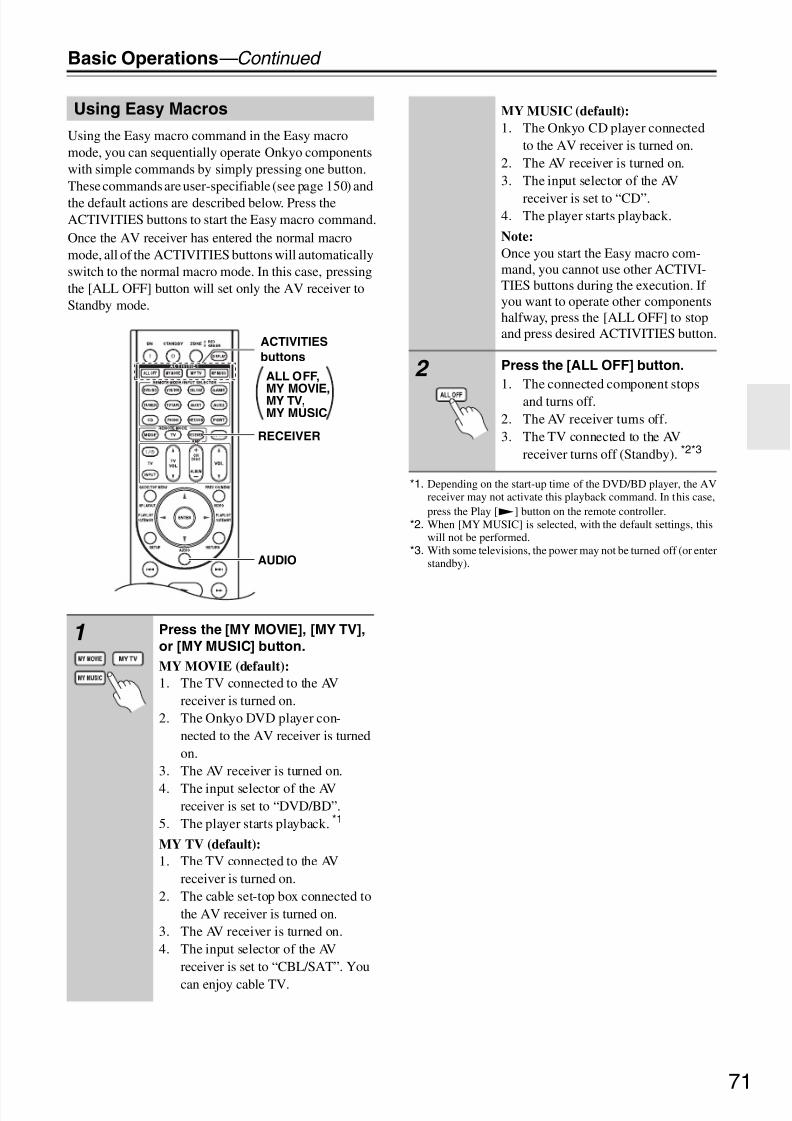
8/8/2019 Manual TX-NR5007 English
http://slidepdf.com/reader/full/manual-tx-nr5007-english 71/16471
Basic Operations—Continued
Using the Easy macro command in the Easy macromode, you can sequentially operate Onkyo componentswith simple commands by simply pressing one button.These commands are user-specifiable (see page 150) andthe default actions are described below. Press theACTIVITIES buttons to start the Easy macro command.Once the AV receiver has entered the normal macromode, all of the ACTIVITIES buttons will automaticallyswitch to the normal macro mode. In this case, pressingthe [ALL OFF] button will set only the AV receiver toStandby mode.
*1. Depending on the start-up time of the DVD/BD player, the AVreceiver may not activate this playback command. In this case,press the Play [1] button on the remote controller.
*2. When [MY MUSIC] is selected, with the default settings, thiswill not be performed.
*3. With some televisions, the power may not be turned off (or enterstandby).
Using Easy Macros
1 Press the [MY MOVIE], [MY TV],
or [MY MUSIC] button.
MY MOVIE (default):
1. The TV connected to the AVreceiver is turned on.
2. The Onkyo DVD player con-nected to the AV receiver is turnedon.
3. The AV receiver is turned on.
4. The input selector of the AVreceiver is set to “DVD/BD”.
5. The player starts playback. *1
MY TV (default):
1. The TV connected to the AVreceiver is turned on.
2. The cable set-top box connected tothe AV receiver is turned on.
3. The AV receiver is turned on.4. The input selector of the AV
receiver is set to “CBL/SAT”. You
can enjoy cable TV.
ALL OFF,
MY MOVIE,MY TV,MY MUSIC
RECEIVER
AUDIO
ACTIVITIES
buttons
MY MUSIC (default):
1. The Onkyo CD player connectedto the AV receiver is turned on.
2. The AV receiver is turned on.3. The input selector of the AV
receiver is set to “CD”.4. The player starts playback.
Note:
Once you start the Easy macro com-mand, you cannot use other ACTIVI-TIES buttons during the execution. If you want to operate other componentshalfway, press the [ALL OFF] to stopand press desired ACTIVITIES button.
2 Press the [ALL OFF] button.
1. The connected component stopsand turns off.
2. The AV receiver turns off.3. The TV connected to the AV
receiver turns off (Standby). *2*3

8/8/2019 Manual TX-NR5007 English
http://slidepdf.com/reader/full/manual-tx-nr5007-english 72/16472
Basic Operations—Continued
Changing Source Component
When you want to operate the component that is notassigned as the source component, you can assign it asthe source component. For the default assignment, seepage 151.
Restoring Default
(3 seconds)
While holding down the REMOTE
MODE button, press and hold
down the [MY MOVIE], [MY TV],
or [MY MUSIC] button (about 3
seconds).
The ACTIVITIES buttons that youpressed flashes twice, indicating thatthe setting has been established.
Examples:
When you press the [MY MUSIC] but-
ton and want to start the Onkyo Cas-sette recorder, while holding down[TV/TAPE] button, press and holddown the [MY MUSIC] button (about3 seconds) flashes twice.
Tip:
This procedure can also be performedvia onscreen menu (see page 150).
1
(3 seconds)
While holding down the [AUDIO]
button, press and hold down the
[ALL OFF] button until the [ALL
OFF] button lights up (about 3seconds).
2 Release the [AUDIO] and [ALL
OFF] buttons and press the [ALL
OFF] button again.
The [ALL OFF] button flashes twice.

8/8/2019 Manual TX-NR5007 English
http://slidepdf.com/reader/full/manual-tx-nr5007-english 73/16473
Listening to the Radio
With the built-in tuner you can enjoy AM and FM radiostations. You can store your favorite stations as presetsfor quick selection.
Listening to the Radio
Tuning into Radio Stations
Auto Tuning Mode
When tuned into a station, the TUNED indicator
appears. When tuned into a stereo FM station, the FMSTEREO indicator appears on the display, as shown.
Manual Tuning Mode
This model changes FM/AM frequency in 200k/10k (or50k/9k) Hz steps.In Manual Tuning mode, FM stations will be in mono.
Tuning into weak FM stereo stations
If the signal from a stereo FM station is weak, it may beimpossible to get good reception. In this case, switch toManual Tuning mode and listen to the station in mono.
Tuning into Stations by Frequency
You can tune into AM and FM stations directly by enter-ing the appropriate frequency.
Using the Tuner
Use the [TUNER] input selector
button to select either AM or FM.
In this example, FM has been selected.Each time you press the [TUNER] but-ton, the input source changes betweenAM and FM.
(Actual display depends on country.)
1 Press the [TUNING MODE] but-
ton so that the AUTO indicator
appears on the display.
2 Press the TUNING Up or Down
[q]/[w] buttons.
Searching stops when a station isfound.
TUNER
TUNING MODE TUNING /
Band Frequency
1 Press the [TUNING MODE] but-
ton so that the AUTO indicator
disappears from the display.
2 Press and hold the TUNING Up or
Down [q]/[w] buttons.The frequency stops changing whenyou release the button.Press the buttons repeatedly to changethe frequency one step at a time.
1Remote
controller
Press the [TUNER] button repeat-
edly to select AM or FM, followed
by the [D.TUN] button.
(Actual display depends on country.)
2 Within 8 seconds, use the num-
ber buttons to enter the fre-
quency of the radio station.
For example, to tune to 87.5 (FM),press 8, 7, 5.
TUNED
FM STEREO
AUTO

8/8/2019 Manual TX-NR5007 English
http://slidepdf.com/reader/full/manual-tx-nr5007-english 74/16474
Listening to the Radio—Continued
You can store a combination of up to 40 of your favoriteAM/FM radio stations as presets.
Note:
You can name your radio presets for easy identification(see page 105). Its name is displayed instead of the bandand frequency.
Selecting Presets
Deleting Presets
Presetting AM/FM Stations
1 Tune into the AM/FM station that
you want to store as a preset.
2 Press the [MEMORY] button.
The preset number flashes.
3 While the preset number is flash-
ing (about 8 seconds), use the
PRESET [e]/[r] buttons to
select a preset from 1 through 40.
4 Press the [MEMORY] button
again to store the station or
channel.
The station or channel is stored and thepreset number stops flashing.Repeat this procedure for all of yourfavorite AM/FM radio stations.
MEMORY PRESETe / r
PRESETe / r
AV receiver
orRemote
controller
or
To select a preset, use the PRE-
SET [e]/[r] buttons, or the
remote controller’s CH [+/–] but-
ton.
Remotecontroller
You can also use the remote con-
troller’s number buttons to selecta preset directly.
1 Select the preset that you want to
delete.
See the previous section.
2 While holding down the [MEM-
ORY] button, press the [TUNING
MODE] button.
The preset is deleted and its numberdisappears from the display.
MEMORY, TUNING MODE

8/8/2019 Manual TX-NR5007 English
http://slidepdf.com/reader/full/manual-tx-nr5007-english 75/164

8/8/2019 Manual TX-NR5007 English
http://slidepdf.com/reader/full/manual-tx-nr5007-english 76/16476
Listening to the Radio—Continued
When tuned to an RDS station that’s broadcasting text information, the text can be displayed.
Displaying Radio Text (RT)
Notes:
• The message “Waiting” may appear while the AVreceiver waits for the RT information.
• If the message “No Text Data” appears on the display,no RT information is available.
Finding Stations by Type (PTY)
You can search for radio stations by type.
Listening to Traffic News (TP)
You can search for stations that broadcast traffic news.
Press the [RT/PTY/TP] button
once.
The RT information scrolls across thedisplay.
1 Press the [RT/PTY/TP] button
twice.
The current program type appears onthe display.
2 Use the PRESET [e]/[r] buttons
to select the type of program you
want.
See the table on page 75.
RT/PTY/TP
PRESETe
/ r
ENTERRT/PTY/TP
3 To start the search, press
[ENTER].
The AV receiver searches until it finds
a station of the type you specified, atwhich point it stops briefly before con-tinuing with the search.
4 When a station you want to listen
to is found, press [ENTER].
If no stations are found, the message“Not Found” appears.
1Press the [RT/PTY/TP] button
three times.
If the current radio station is broadcast-ing TP (Traffic Program), “[TP]” willappear on the display, and traffic newswill be heard as and when it’s broad-cast. If “TP” without square bracketsappears, this means that the station isnot broadcasting TP.
2 To locate a station that is broad-
casting TP, press [ENTER].
The AV receiver searches until it findsa station that’s broadcasting TP.If no stations are found, the message“Not Found” appears.
ENTERRT/PTY/TP
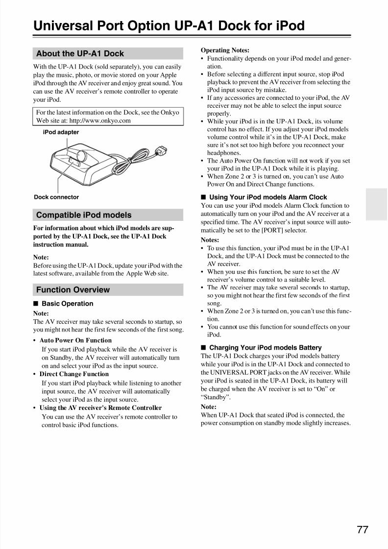
8/8/2019 Manual TX-NR5007 English
http://slidepdf.com/reader/full/manual-tx-nr5007-english 77/16477
Universal Port Option UP-A1 Dock for iPod
With the UP-A1 Dock (sold separately), you can easilyplay the music, photo, or movie stored on your AppleiPod through the AV receiver and enjoy great sound. Youcan use the AV receiver’s remote controller to operateyour iPod.
For information about which iPod models are sup-
ported by the UP-A1 Dock, see the UP-A1 Dock
instruction manual.
Note:
Before using the UP-A1 Dock, update your iPod with thelatest software, available from the Apple Web site.
Basic Operation
Note:
The AV receiver may take several seconds to startup, soyou might not hear the first few seconds of the first song.
• Auto Power On Function
If you start iPod playback while the AV receiver ison Standby, the AV receiver will automatically turnon and select your iPod as the input source.
• Direct Change Function
If you start iPod playback while listening to anotherinput source, the AV receiver will automaticallyselect your iPod as the input source.
• Using the AV receiver's Remote Controller
You can use the AV receiver’s remote controller tocontrol basic iPod functions.
Operating Notes:
• Functionality depends on your iPod model and gener-ation.
• Before selecting a different input source, stop iPodplayback to prevent the AV receiver from selecting theiPod input source by mistake.
• If any accessories are connected to your iPod, the AVreceiver may not be able to select the input sourceproperly.
• While your iPod is in the UP-A1 Dock, its volumecontrol has no effect. If you adjust your iPod modelsvolume control while it’s in the UP-A1 Dock, makesure it’s not set too high before you reconnect yourheadphones.
• The Auto Power On function will not work if you setyour iPod in the UP-A1 Dock while it is playing.
• When Zone 2 or 3 is turned on, you can’t use AutoPower On and Direct Change functions.
Using Your iPod models Alarm Clock
You can use your iPod models Alarm Clock function toautomatically turn on your iPod and the AV receiver at aspecified time. The AV receiver’s input source will auto-matically be set to the [PORT] selector.
Notes:
• To use this function, your iPod must be in the UP-A1Dock, and the UP-A1 Dock must be connected to theAV receiver.
• When you use this function, be sure to set the AVreceiver’s volume control to a suitable level.
• The AV receiver may take several seconds to startup,so you might not hear the first few seconds of the firstsong.
• When Zone 2 or 3 is turned on, you can’t use this func-tion.
• You cannot use this function for sound effects on youriPod.
Charging Your iPod models Battery
The UP-A1 Dock charges your iPod models batterywhile your iPod is in the UP-A1 Dock and connected tothe UNIVERSAL PORT jacks on the AV receiver. Whileyour iPod is seated in the UP-A1 Dock, its battery willbe charged when the AV receiver is set to “On” or“Standby”.
Note:
When UP-A1 Dock that seated iPod is connected, thepower consumption on standby mode slightly increases.
About the UP-A1 Dock
For the latest information on the Dock, see the OnkyoWeb site at: http://www.onkyo.com
Compatible iPod models
Function Overview
Dock connector
iPod adapter

8/8/2019 Manual TX-NR5007 English
http://slidepdf.com/reader/full/manual-tx-nr5007-english 78/16478
Universal Port Option UP-A1 Dock for iPod—Continued
By pressing the REMOTE MODE button that’s beenprogrammed with the remote control code for yourDock, you can control your iPod in the Dock with thefollowing buttons.The [PORT] button is preprogrammed with the remotecontrol code for controlling a Dock with Universal Portconnector.For details on entering a remote control code, seepage 141.
When Using a Dock with Universal Port connector:
• Connect the Dock to the UNIVERSAL PORT jack.• See the Dock’s instruction manual for more informa-
tion.You can control your iPod when “PORT” is selected asthe input source.
Notes:
• With some iPod models and generations, certain but-tons may not work as expected.• For detailed operation of the iPod, please refer to the
instruction manual.
a Arrow [q]/[w] and ENTER buttons
Used to navigate menus and select items.
b Previous [7] button
Restarts the current song. Press it again to select theprevious song.
c Fast Reverse [5] buttonPress and hold to fast reverse.
d Pause [3] button
Pauses playback. Press it again to start playback.
e REPEAT button
Used with the repeat function.
f DISPLAY button
Select Standard or Extended mode*1.
g MUTING button (69)
Mutes or unmutes the AV receiver.
h ALBUM +/– buttonSelects the next or previous album.
i VOL [q]/[w] button (67)
Adjusts the volume of the AV receiver.
j PLAYLIST [e]/[r] buttons
Selects the previous or next playlist on the iPod.
k RETURN button
Exits the menu or returns to the previous menu.
l Play [1] button
Starts playback. If the component is off, it will turnon automatically.
m Next [6] button
Selects the next song.
n Fast Forward [4] button
Press and hold to fast forward.
o Stop [2] button
Stops playback and displays a menu.
p RANDOM button
Used with the shuffle function.
*1
Standard mode
Nothing is displayed on your TV and you navigate andselect your contents by using your iPod’s display.Only this mode can playback the video.
Extended mode
Playlists (artists, albums, songs, and so on) are displayedon your TV, and you can navigate and select your musicwhile looking at your TV.
Notes:
• In Extended mode, the playback will be continuedeven if the AV receiver is turned off.
• In Extended mode, you cannot operate your iPod
directly.• In Extended mode, it may take some time to acquirethe contents.
• In Extended mode, video contents can not display onyour TV.
Controlling iPod
o
n
l
m
p
g
i
k
j
f
d
bc
a
h
e
Press [PORT] button first.

8/8/2019 Manual TX-NR5007 English
http://slidepdf.com/reader/full/manual-tx-nr5007-english 79/16479
Universal Port Option UP-A1 Dock for iPod—Continued
Status messages
PORT Reading
The AV receiver is checking the connection with thedock.
PORT Not Support
The AV receiver do not support the connected dock.
PORT UP-A1
UP-A1 Dock is connected.
Notes:
• The AV receiver displays the message “UP-A1” forseveral seconds after recognizing the UP-A1.
• When the status message is not displayed on the AVreceiver’s display, check the connection to your iPod.

8/8/2019 Manual TX-NR5007 English
http://slidepdf.com/reader/full/manual-tx-nr5007-english 80/16480
Recording
This section explains how to record the selected inputsource to a component with recording capability, andhow to record audio and video from different sources.
Notes:
• The surround sound and DSP listening modes cannotbe recorded.
• Copy-protected DVDs cannot be recorded.• Sources connected to a digital input cannot be
recorded. Only analog inputs can be recorded.• DTS signals will be recorded as noise, so don’t
attempt analog recording of DTS CDs or LDs.• While the listening mode is set to Pure Audio, no
image is provided because the power is turned off forthe video circuit. If you want to make recordings,select other listening mode.
AV Recording
Audio sources can be recorded to a recorder (e.g., cas-sette deck, CDR, MD) connected to the TV/TAPE OUT jack. Video sources can be recorded to a video recorder(e.g., VCR, DVD recorder) connected to the VCR/DVROUT jack. See pages 32 to 47 for hookup information.
Recording Separate AV Sources
Here you can record audio and video from completelyseparate sources, allowing you to overdub audio ontoyour video recordings. This function takes advantage of the fact that when an audio-only input source (i.e., TV/
TAPE, TUNER, CD or PHONO) is selected, the videoinput source remains unchanged.In the following example, audio from the CD player con-nected to the CD IN, and video from the camcorder con-nected to the AUX 1 INPUT VIDEO jack are recordedby the VCR connected to the VCR/DVR OUT jacks.
1 Use the input selector buttons to
select the source that you want
to record.
You can watch the source while record-ing. The AV receiver’s MASTER VOL-UME control has no effect onrecording.
2 On your recorder, start record-
ing.
3 On the source component, start
playback.
If you select another input source dur-ing recording, that input source will be
recorded.
1 Prepare the camcorder and CD player for
playback.
2 Prepare the VCR for recording.
3 Press the [AUX 1] input selector button.
4 Press the [CD] input selector button.
This selects the CD player as the audio source, butleaves the camcorder as the video source.
5 Start recording on the VCR and start play-
back on the camcorder and CD player.
The video from the camcorder and the audio from
the CD player are recorded by the VCR.
Camcorder
VCRCD player
video signal
audio signal
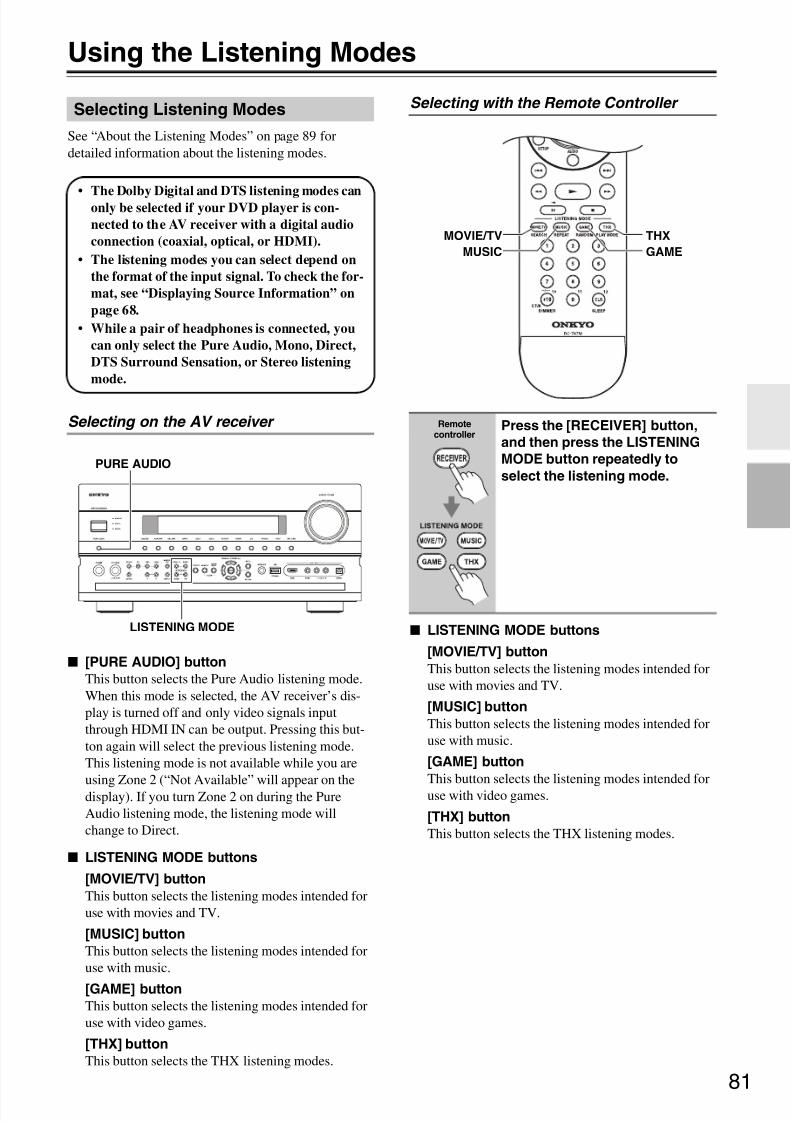
8/8/2019 Manual TX-NR5007 English
http://slidepdf.com/reader/full/manual-tx-nr5007-english 81/16481
Using the Listening Modes
See “About the Listening Modes” on page 89 fordetailed information about the listening modes.
Selecting on the AV receiver
[PURE AUDIO] button
This button selects the Pure Audio listening mode.When this mode is selected, the AV receiver’s dis-play is turned off and only video signals inputthrough HDMI IN can be output. Pressing this but-ton again will select the previous listening mode.This listening mode is not available while you are
using Zone 2 (“Not Available” will appear on thedisplay). If you turn Zone 2 on during the PureAudio listening mode, the listening mode willchange to Direct.
LISTENING MODE buttons
[MOVIE/TV] button
This button selects the listening modes intended foruse with movies and TV.
[MUSIC] button
This button selects the listening modes intended foruse with music.
[GAME] button
This button selects the listening modes intended foruse with video games.
[THX] button
This button selects the THX listening modes.
Selecting with the Remote Controller
LISTENING MODE buttons
[MOVIE/TV] button
This button selects the listening modes intended foruse with movies and TV.
[MUSIC] button
This button selects the listening modes intended foruse with music.
[GAME] button
This button selects the listening modes intended foruse with video games.
[THX] button
This button selects the THX listening modes.
Selecting Listening Modes
• The Dolby Digital and DTS listening modes canonly be selected if your DVD player is con-
nected to the AV receiver with a digital audio
connection (coaxial, optical, or HDMI).
• The listening modes you can select depend on
the format of the input signal. To check the for-
mat, see “Displaying Source Information” on
page 68.
• While a pair of headphones is connected, you
can only select the Pure Audio, Mono, Direct,
DTS Surround Sensation, or Stereo listening
mode.
PURE AUDIO
LISTENING MODE
Remotecontroller
Press the [RECEIVER] button,
and then press the LISTENING
MODE button repeatedly to
select the listening mode.
MOVIE/TV
MUSIC
THX
GAME

8/8/2019 Manual TX-NR5007 English
http://slidepdf.com/reader/full/manual-tx-nr5007-english 82/16482
Using the Listening Modes—Continued
Mono/Multiplex Sources
: Available Listening Modes
Notes:*1 For 7ch output, output can be switched between Front high or Front wide speakers by pressing the [SP LAYOUT] button (depending on the
“Speaker Configuration” setting (see page 95)). *2 For 9ch output, output can be switched between the combination of Surround back and Front high, or Surround back and Front widespeakers by pressing the [SP LAYOUT] button.
*5 This listening mode is not available while you are using Zone 2 (“Not Available” will appear on the display). If you turn Zone 2 on duringthe Pure Audio listening mode, the listening mode will change to Direct.
• Available sampling rate for PCM input signal is 32/44.1/48/88.2/96/176.4/192kHz.• The listening modes cannot be selected with some source formats.
Listening Modes Available for Each Source Format
The Speaker layout illustration
shows which speakers are set to
active in the “Speaker Configu-
ration” setting (see page 95).
The LISTENING MODE button
illustration shows that listening
modes can be selected.
Listening Mode Button
Speaker layout
Pure Audio*5
Direct
Stereo
Mono
Orchestra *1*2
Unplugged *1*2
Studio-Mix *1*2
TV Logic *1*2
Game-RPG *1*2
Game-Action *1*2
Game-Rock *1*2
Game-Sports *1*2
All Ch Stereo *1*2
Full Mono *1*2
T-D (Theater-Dimensional)
DTS SurroundSensation
FL
LW
LH
CRH
RW
FR
SR
SBR
SBL
SL
SW
LH RH
SBRSBL
FL FRLW RWC
SL SR
SW SW
C
C
: Front left speaker
: Center speaker
: Surround left speaker
: active in the speaker settings
: non-active in the speaker settings
: Front right speaker
: Subwoofer
: Surround right speaker
: Surround back right speaker
: Surround back left speaker
: Front high left speaker
: Front high right speaker
: Front wide left speaker
: Front wide right speaker
LH RH
SBRSBL
FL FRLW RWC
SL SR
SW SW
LH RH
SBRSBL
FL FRLW RWC
SL SR
SW SW
LH RH
SBRSBL
FL FRLW RWC
SL SR
SW SW
LH RH
SBRSBL
FL FRLW RWC
SL SR
SW
*1 *1
*2*2
*1 *1*2
*2 *2
*2
SW

8/8/2019 Manual TX-NR5007 English
http://slidepdf.com/reader/full/manual-tx-nr5007-english 83/16483
Using the Listening Modes—Continued
Stereo Source (1/2)
: Available Listening Modes
Listening Mode Button
Speaker layout
Pure Audio*5
Direct
Stereo
Mono
PLII/PLIIxMovie*3
PLII/PLIIx
Music*3
PLII/PLIIx
Game*3
PLIIz Height
Neo:6 Cinema
Neo:6 Music
Neural
Surround
Neural DigitalMusic
PLII/PLIIx
Movie*3
THX Cinema
PLII/PLIIx Movie
Audyssey DSX*4 *2
PLllz Height
THX Cinema
Neo:6 Cinema
THX Cinema
Neo:6 Cinema
Audyssey DSX*
4 *2
Neural THX
Cinema
PLII/PLIIx
Music*3
THX Music
PLII/PLIIx Music
Audyssey DSX*4 *2
PLllz Height
THX Music
Neo:6 Music
THX Music
Neo:6 Music
Audyssey DSX*4
*2
Neural Digital
Music
THX Music
LH RH
SBRSBL
FL FRLW RWC
SL SR
SW SW
LH RH
SBRSBL
FL FRLW RWC
SL SR
SW SW
LH RH
SBRSBL
FL FRLW RWC
SL SR
SW SW
LH RH
SBRSBL
FL FRLW RWC
SL SR
SW
*1 *1
*2*2
*1 *1 *2*2
*2 *2SW

8/8/2019 Manual TX-NR5007 English
http://slidepdf.com/reader/full/manual-tx-nr5007-english 84/16484
Using the Listening Modes—Continued
Stereo Source (2/2)
: Available Listening Modes
Notes:*1 For 7ch output, output can be switched between Front high or Front wide speakers by pressing the [SP LAYOUT] button (depending on the
“Speaker Configuration” setting (see page 95)). *2 For 9ch output, output can be switched between the combination of Surround back and Front high, or Surround back and Front wide
speakers by pressing the [SP LAYOUT] button. *3 If there are no surround back speakers, or Powered Zone 3 is being used, Dolby Pro Logic II is used.*4 • This listening mode can be selected only when all the following conditions are satisfied:
a. Center speaker is connected to the AV receiver.b. Either of Front High speakers or Front Wide speakers is connected to the AV receiver.
• Output can be switched between Front high or Front wide speakers by pressing the [SP LAYOUT] button (depending on the “SpeakerConfiguration” setting (see page 95)).
*5 This listening mode is not available while you are using Zone 2 (“Not Available” will appear on the display). If you turn Zone 2 on duringthe Pure Audio listening mode, the listening mode will change to Direct.
• Available sampling rate for PCM input signal is 32/44.1/48/88.2/96/176.4/192kHz.• The listening modes cannot be selected with some source formats.
Listening Mode Button
Speaker layout
PLII/PLIIxGame*3 THX Games
PLII/PLIIx GameAudyssey DSX*4
*2
PLllz HeightTHX Games
Neural THX
Games
PLII Game THXUltra2 Games
PLIIz Height THXUltra2 Games
Orchestra *1*2
Unplugged *1*2
Studio-Mix *1*2
TV Logic *1*2
Game-RPG *1*2
Game-Action *1*2
Game-Rock *1*2
Game-Sports *1*2
All Ch Stereo *1*2
Full Mono *1*2
T-D (Theater-Dimensional)
Neo:6 Cinema
DTS SurroundSensation
Neo:6 MusicDTS SurroundSensation
LH RH
SBRSBL
FL FRLW RWC
SL SR
SW SW
LH RH
SBRSBL
FL FRLW RWC
SL SR
SW SW
LH RH
SBRSBL
FL FRLW RWC
SL SR
SW SW
LH RH
SBRSBL
FL FRLW RWC
SL SR
SW
*1 *1
*2*2
*1 *1 *2*2
*2 *2SW
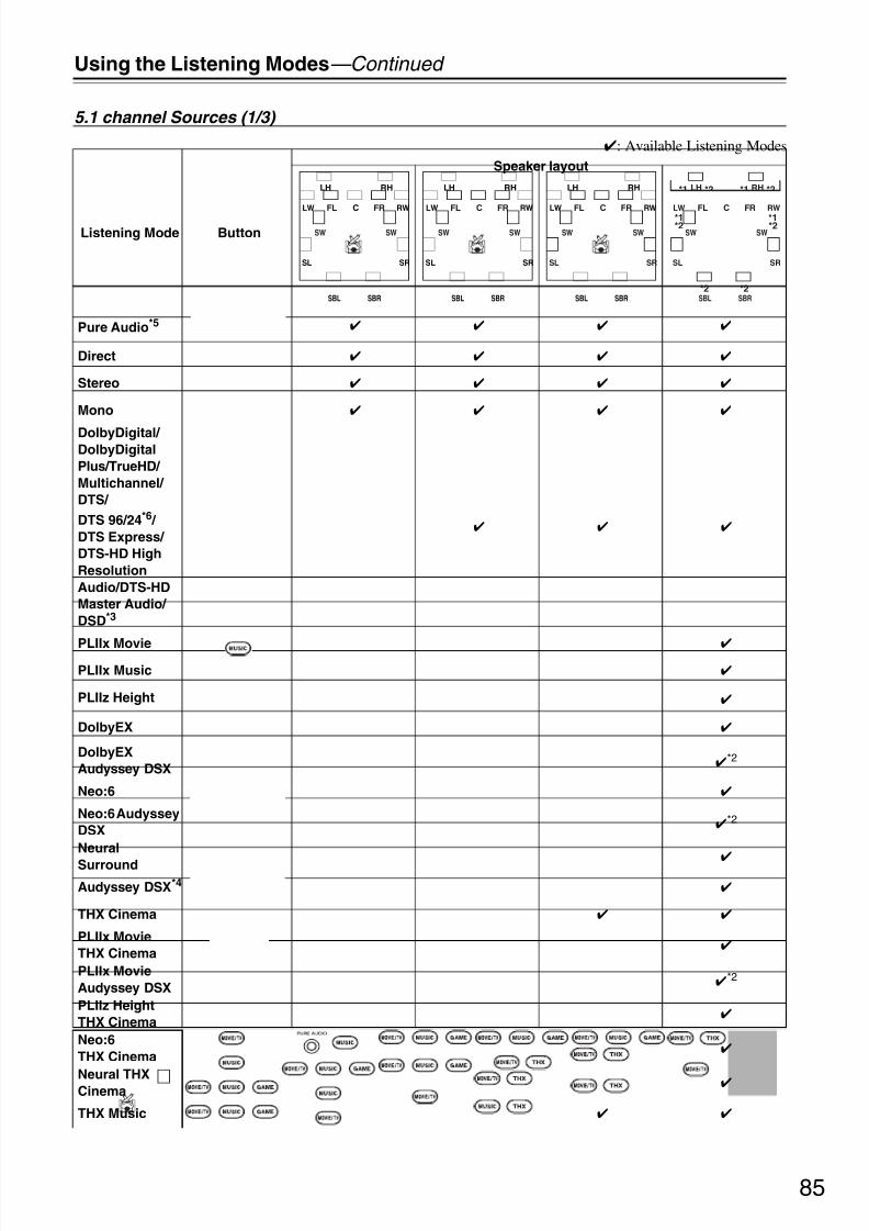
8/8/2019 Manual TX-NR5007 English
http://slidepdf.com/reader/full/manual-tx-nr5007-english 85/16485
Using the Listening Modes—Continued
5.1 channel Sources (1/3)
: Available Listening Modes
Listening Mode Button
Speaker layout
Pure Audio*5
Direct
Stereo
Mono
DolbyDigital/ DolbyDigital
Plus/TrueHD/
Multichannel/
DTS/
DTS 96/24*6 /
DTS Express/
DTS-HD High
Resolution
Audio/DTS-HD
Master Audio/
DSD*3
PLIIx Movie
PLIIx Music
PLIIz Height
DolbyEX
DolbyEX
Audyssey DSX
*2
Neo:6
Neo:6 Audyssey
DSX
*2
Neural
Surround
Audyssey DSX*4
THX Cinema
PLIIx Movie
THX Cinema
PLIIx Movie
Audyssey DSX
*2
PLIIz Height
THX Cinema
Neo:6
THX Cinema
Neural THXCinema
THX Music
LH RH
SBRSBL
FL FRLW RWC
SL SR
SW SW
LH RH
SBRSBL
FL FRLW RWC
SL SR
SW SW
LH RH
SBRSBL
FL FRLW RWC
SL SR
SW SW
LH RH
SBRSBL
FL FRLW RWC
SL SR
SW
*1 *1
*2*2
*1 *1 *2*2
*2 *2SW

8/8/2019 Manual TX-NR5007 English
http://slidepdf.com/reader/full/manual-tx-nr5007-english 86/16486
Using the Listening Modes—Continued
5.1 channel Sources (2/3)
: Available Listening Modes
Listening Mode Button
Speaker layout
PLIIx Music
THX Music
PLIIx Music
Audyssey DSX
*2
PLIIz Height
THX Music
Neo:6 THX
Music
Neural THX
Music
THX Games
PLIIx Height
THX Games
Neo:6 THX
Games
Neural THX
Games
THX Surround
EX
THX Ultra2Cinema
PLIIz THX Ultra2
Cinema
THX Ultra2
Music
PLIIz THX Ultra2
Music
THX Ultra2
Games
PLIIz THX Ultra2
Games
Orchestra
*1*2
Unplugged *1*2
Studio-Mix *1*2
TV Logic *1*2
Game-RPG *1*2
Game-Action *1*2
Game-Rock *1*2
Game-Sports *1*2
All Ch Stereo *1*2
Full Mono *1*2
LH RH
SBRSBL
FL FRLW RWC
SL SR
SW SW
LH RH
SBRSBL
FL FRLW RWC
SL SR
SW SW
LH RH
SBRSBL
FL FRLW RWC
SL SR
SW SW
LH RH
SBRSBL
FL FRLW RWC
SL SR
SW
*1 *1
*2*2
*1 *1 *2*2
*2 *2SW

8/8/2019 Manual TX-NR5007 English
http://slidepdf.com/reader/full/manual-tx-nr5007-english 87/16487
Using the Listening Modes—Continued
5.1 channel Sources (3/3)
: Available Listening Modes
Notes:*1 For 7ch output, output can be switched between Front high or Front wide speakers by pressing the [SP LAYOUT] button (depending on the
“Speaker Configuration” setting (see page 95)). *2 For 9ch output, output can be switched between the combination of Surround back and Front high, or Surround back and Front wide
speakers by pressing the [SP LAYOUT] button.*3 AV receiver can input the DSD signal from HDMI IN. Setting the output setting on the player side to PCM might obtain a better sound
according to the player. In that case, set the output setting on the player side to PCM. *4 • This listening mode can be selected only when all the following conditions are satisfied:
a. Center speaker is connected to the AV receiver.b. Either of Front High speakers or Front Wide speakers is connected to the AV receiver.
• Output can be switched between Front high or Front wide speakers by pressing the [SP LAYOUT] button (depending on the “SpeakerConfiguration” setting (see page 95)).
*5 This listening mode is not available while you are using Zone 2 (“Not Available” will appear on the display). If you turn Zone 2 on duringthe Pure Audio listening mode, the listening mode will change to Direct.
*6 Depending on the input source, DTS is used.
• Available sampling rate for PCM input signal is 32/44.1/48/88.2/96/176.4/192kHz.
• The listening modes cannot be selected with some source formats.
Listening Mode Button
Speaker layout
T-D (Theater-
Dimensional)
DTS Surround
Sensation
LH RH
SBRSBL
FL FRLW RWC
SL SR
SW SW
LH RH
SBRSBL
FL FRLW RWC
SL SR
SW SW
LH RH
SBRSBL
FL FRLW RWC
SL SR
SW SW
LH RH
SBRSBL
FL FRLW RWC
SL SR
SW
*1 *1
*2*2
*1 *1 *2*2
*2 *2SW

8/8/2019 Manual TX-NR5007 English
http://slidepdf.com/reader/full/manual-tx-nr5007-english 88/16488
Using the Listening Modes—Continued
7.1 channel Sources
: Available Listening Modes
Listening Mode Button
Speaker layout
Pure Audio*5
Direct
Stereo
Mono
Multichannel/ DolbyDigital
Plus/TrueHD/
DTS-HD High
Resolution
Audio/DTS-HD
Master Audio/
DTS-ES
Discrete*6 /
DTS-ES Matrix*6
*3
PLIIz Height
Audyssey DSX*4 *2
THX Cinema
PLIIz Height
THX Cinema
THX Music
PLIIz Height
THX Music
THX Games
PLIIz Height
THX Games
Orchestra *1*2
Unplugged *1*2
Studio-Mix *1*2
TV Logic *1*2
Game-RPG *1*2
Game-Action *1*2
Game-Rock *1*2
Game-Sports *1*2
All Ch Stereo *1*2
Full Mono
*1*2
T-D (Theater-
Dimensional)
DTS Surround
Sensation
LH RH
SBRSBL
FL FRLW RWC
SL SR
SW SW
LH RH
SBRSBL
FL FRLW RWC
SL SR
SW SW
LH RH
SBRSBL
FL FRLW RWC
SL SR
SW SW
LH RH
SBRSBL
FL FRLW RWC
SL SR
SW
*1 *1
*2*2
*1 *1 *2*2
*2 *2SW

8/8/2019 Manual TX-NR5007 English
http://slidepdf.com/reader/full/manual-tx-nr5007-english 89/16489
Using the Listening Modes—Continued
Notes:*1 For 7ch output, output can be switched between Front high or Front wide speakers by pressing the [SP LAYOUT] button (depending on the
“Speaker Configuration” setting (see page 95)). *2 For 9ch output, output can be switched between the combination of Surround back and Front high, or Surround back and Front wide
speakers by pressing the [SP LAYOUT] button. *3 Based on the audio channels contained in the source, the corresponding speakers will output the sound. *4 • This listening mode can be selected only when all the following conditions are satisfied:
a. Center speaker is connected to the AV receiver.b. Either of Front High speakers or Front Wide speakers is connected to the AV receiver.
• Output can be switched between Front high or Front wide speakers by pressing the [SP LAYOUT] button (depending on the “SpeakerConfiguration” setting (see page 95)).
*5 This listening mode is not available while you are using Zone 2 (“Not Available” will appear on the display). If you turn Zone 2 on duringthe Pure Audio listening mode, the listening mode will change to Direct.
*6 If there are no surround back speakers, DTS is used.
• Available sampling rate for PCM input signal is 32/44.1/48/88.2/96/176.4/192kHz.• The listening modes cannot be selected with some source formats.
The AV receiver’s listening modes can transform your
listening room into a movie theater or concert hall, withhigh fidelity and stunning surround sound.
Pure Audio
In this mode, the display and video circuitry are turnedoff, minimizing possible noise sources for the ultimate inhigh-fidelity reproduction. (As the video circuitry isturned off, only video signals input through HDMI INcan be output.)
Direct
In this mode, audio from the input source is outputdirectly with minimal processing, providing high-fidel-
ity reproduction. All of the source’s audio channels areoutput as they are.
Stereo
Sound is output by the front left and right speakers andsubwoofer.
Mono
Use this mode when watching an old movie with a monosoundtrack, or use it with the foreign languagesoundtracks recorded in the left and right channels of some movies. It can also be used with DVDs or othersources containing multiplexed audio, such as karaoke
DVDs.Multichannel
This mode is for use with PCM multichannel sources.
Dolby Pro Logic IIx
Dolby Pro Logic II
Dolby Pro Logic IIx expands any 2-channel source for7.1-channel playback. It provides a very natural andseamless surround-sound experience that fully envelopsthe listener. As well as music and movies, video gamescan also benefit from the dramatic spatial effects andvivid imaging. If you’re not using any surround back
speakers, Dolby Pro Logic II will be used instead of Dolby Pro Logic IIx.
• Dolby PLIIx Movie
Use this mode with any stereo or Dolby Surround(Pro Logic) movie (e.g., TV, DVD, VHS).
• Dolby PLIIx Music
Use this mode with any stereo or Dolby Surround(Pro Logic) music source (e.g., CD, radio, cassette,
TV, VHS, DVD).• Dolby PLIIx Game
Use this mode with video games, especially thosethat bear the Dolby Pro Logic II logo.
Dolby Pro Logic IIz Height
Dolby Pro Logic IIz Height is designed to more effec-tively use existing program material when height chan-nel speaker outputs are present. Dolby Pro Logic IIz
Height can be used to upmix a variety of sources frommovies and music, but are particularly well-suited toupmix game content.
Dolby Digital
Use this mode with DVDs that bear the Dolby Digitallogo, and Dolby Digital TV broadcasts. This is the mostcommon digital surround-sound format, and it’ll put youright in the middle of the action, just like being in amovie theater or concert hall.
Audyssey Dynamic Surround Expansion™
Audyssey Dynamic Surround Expansion™ is a scalablesystem that adds new speakers to improve surroundimpression. Starting with a 5.1 system Dynamic Sur-round Expansion first adds Wide channels for the biggest
impact on envelopment. Research in human hearing hasproven that information from the Wide channels is muchmore critical in the presentation of a realistic soundstagethan then Back Surround channels found in traditional7.1 systems. Dynamic Surround Expansion then createsa pair of Height channels to reproduce the next mostimportant acoustical and perceptual cues. In addition tothese new Wide and Height channels, Dynamic Sur-round Expansion applies Surround Envelopment Pro-cessing to enhance the blend between the front andsurround channels.
About the Listening Modes

8/8/2019 Manual TX-NR5007 English
http://slidepdf.com/reader/full/manual-tx-nr5007-english 90/16490
Using the Listening Modes—Continued
5.1-channel source + Dolby EX
These modes expand 5.1-channel sources for 6.1/7.1-channel playback. They’re especially suited to Dolby EXsoundtracks that include a matrix-encoded surroundback channel. The additional channel adds an extradimension and provides an enveloping surround sound
experience, perfect for rotating and fly-by sound effects.Dolby Digital Plus
Developed for use with HDTV, including the new videodisc formats Blu-ray and HD DVD, this is the latest mul-tichannel audio format from Dolby. It supports up to 7.1channels with 48 kHz sampling rate.
Dolby TrueHD
Designed to take full advantage of the additional storagespace offered by the new Blu-ray and HD DVD disc for-mats, this new Dolby format offers up to 7.1 discretechannels of digital audio with 48/96 kHz, up to 5.1-chan-
nels with 192 kHz sampling rate.5.1-channel source + Dolby PLIIx Music
These modes use the Dolby Pro Logic IIx Music modeto expand 5.1-channel sources for 6.1/7.1-channel play-back.
5.1-channel source + Dolby PLIIx Movie
These modes use the Dolby Pro Logic IIx Movie modeto expand 5.1-channel sources for 7.1-channel playback.
DTS
The DTS digital surround-sound format supports up to5.1 discrete channels and uses less compression for high-
fidelity reproduction. Use it with DVDs and CDs thatbear the DTS logo.
DTS 96/24
This mode is for use with DTS 96/24 sources. This ishigh-resolution DTS with a 96 kHz sampling rate and24-bit resolution, providing superior fidelity. Use it withDVDs that bear the DTS 96/24 logo.
DTS-ES Discrete
This mode is for use with DTS-ES Discrete soundtracks,which use a discrete surround back channel for true 6.1/ 7.1-channel playback. The seven totally separate audio
channels provide better spatial imaging and 360-degreesound localization, perfect for sounds that pan across thesurround channels. Use it with DVDs that bear the DTS-ES logo, especially those with a DTS-ES Discretesoundtrack.
DTS-ES Matrix
This mode is for use with DTS-ES Matrix soundtracks,which use a matrix-encoded back-channel for 6.1/7.1-channel playback. Use it with DVDs that bear the DTS-ES logo, especially those with a DTS-ES Matrixsoundtrack.
DTS Neo:6
This mode expands any 2-channel source for up to 7.1-channel playback. It uses seven full-bandwidth channelsof matrix decoding for matrix-encoded material, provid-ing a very natural and seamless surround sound experi-ence that fully envelops the listener.
• Neo:6 Cinema
Use this mode with any stereo movie (e.g., TV,DVD, VHS).
• Neo:6 Music
Use this mode with any stereo music source (e.g.,CD, radio, cassette, TV, VHS, DVD).
5.1-channel source + Neo:6
This mode uses Neo:6 to expand 5.1-channel sources for6.1/7.1-channel playback.
DTS-HD High Resolution Audio
Developed for use with HDTV, including the new videodisc formats Blu-ray and HD DVD, this is the latest mul-tichannel audio format from DTS. It supports up to 7.1channels with 96 kHz sampling rate.
DTS-HD Master Audio
Designed to take full advantage of the additional storagespace offered by the new Blu-ray and HD DVD disc for-mats, this new DTS format offers up to 7.1 discrete chan-nels of digital audio with 48/96 kHz, up to 5.1-channelswith 192 kHz sampling rate.
DTS Express
This format supports up to 5.1 channels and a lower sam-pling rate of 48 kHz. Applications include interactiveaudio and commentary encoding for HD DVD SubAudio and Blu-ray Secondary Audio. Also broadcastand media servers.
Neural Digital Music
Neural Digital Music is a new surround mode specifi-cally designed to enhance the playback of compresseddigital music content. It provides listeners with anexpanded sound stage and clean surround experience,even with compressed audio sources such as MP3s andInternet streams.
DSDDSD stands for Direct Stream Digital and is the formatused to store digital audio on Super Audio CDs (SACD).This mode can be used with Super Audio CDs that fea-ture multichannel audio.
DTS Surround Sensation Speaker
With this mode you can enjoy a virtual 5.1 surroundsound even with only two speakers.
• Neo:6 Cinema + DTS Surround Sensation
• Neo:6 Music + DTS Surround Sensation
These modes use Neo:6 to expand stereo sources for vir-tual surround playback.
DTS Surround Sensation Headphone
DTS Surround Sensation Headphone delivers simulatedvirtual multi-channel surround sound through any stereoheadphones.

8/8/2019 Manual TX-NR5007 English
http://slidepdf.com/reader/full/manual-tx-nr5007-english 91/16491
Using the Listening Modes—Continued
THX
Founded by George Lucas, THX develops stringent stan-dards that ensure movies are reproduced in movie the-aters and home theaters just as the director intended.THX Modes carefully optimize the tonal and spatialcharacteristics of the soundtrack for reproduction in the
home-theater environment. They can be used with 2-channel matrixed and multichannel sources.Surround back speaker output depends on the sourcematerial and the selected listening mode.
• THX Cinema
THX Cinema mode corrects theatrical soundtracksfor playback in a home theater environment. In thismode, THX Loudness Plus is configured for cinemalevels and Re-EQ, Timbre Matching, and AdaptiveDecorrelation are active.
• THX Music
THX Music mode is tailored for listening to music,which is typically mastered at significantly higherlevels than movies. In this mode, THX LoudnessPlus is configured for music playback and only Tim-bre Matching is active.
• THX Games
THX Games mode is meant for spatially accurateplayback of game audio, which is often mixed simi-larly to movies but in a smaller environment. THXLoudness Plus is configured for game audio levels,with Timbre Matching active.
• THX Ultra2 CinemaThis mode expands 5.1-channel sources for 7.1-channel playback. It does this by analyzing the com-position of the surround source, optimizing theambient and directional sounds to produce the sur-round back channel output.
• THX Ultra2 Music
This mode is designed for use with music. It expands5.1-channel sources for 7.1-channel playback.
• THX Ultra2 Games
This mode is designed for use with video games. It
can expand 5.1-channel sources for 6.1/7.1-channelplayback.
• THX Surround EX
This mode expands 5.1-channel sources for 6.1/7.1-channel playback. It’s especially suited to DolbyDigital EX sources. THX Surround EX, also knownas Dolby Digital Surround EX, is a joint develop-ment between Dolby Laboratories and THX Ltd.
Neural Surround
Neural Surround employs psychoacoustic frequencydomain processing, which allows delivery of a more
detailed sound stage, with superior channel separationand localization of audio elements. The Neural Surroundmodes can expand any 2-channel stereo source for 5.1-or 7.1-channel playback, respectively. Use them withCD, radio, cassette, TV, VHS, DVD, and other 2-channel
stereo sources, including video games. Neural Surroundcan also be used by broadcasters to encode and transmitsurround-sound content over a stereo signal, which lis-teners can enjoy as either surround sound or normal ste-reo.
Onkyo Original DSP Modes
Orchestra
Suitable for classical or operatic music, this modeemphasizes the surround channels in order to widen thestereo image, and simulates the natural reverberation of a large hall.
Unplugged
Suitable for acoustic instruments, vocals, and jazz, thismode emphasizes the front stereo image, giving theimpression of being right in front of the stage.
Studio-MixSuitable for rock or pop music, listening to music in thismode creates a lively sound field with a powerful acous-tic image, like being at a club or rock concert.
TV Logic
This mode adds realistic acoustics to TV shows pro-duced in a TV studio, surround effects to the entiresound, and clarity to voices.
Game-RPG
Use this mode when playing role playing game discs.
Game-Action
Use this mode when playing action game discs.Game-Rock
Use this mode when playing rock game discs.
Game-Sports
Use this mode when playing sports game discs.
All Ch Stereo
Ideal for background music, this mode fills the entire lis-tening area with stereo sound from the front, surround,and surround back speakers.
Full Mono
In this mode, all speakers output the same sound in
mono, so the sound you hear is the same regardless of where you are within the listening room.
T-D (Theater-Dimensional)
With this mode you can enjoy a virtual surround soundeven with only two or three speakers. This works by con-trolling how sounds reach the listener’s left and rightears. Good results may not be possible if there’s toomuch reverb, so we recommend that you use this modein an environment with little or no natural reverb.

8/8/2019 Manual TX-NR5007 English
http://slidepdf.com/reader/full/manual-tx-nr5007-english 92/16492
Advanced Setup
The onscreen setup menus appear on the connected TV and provide a convenient way to change the AV receiver’svarious settings. Settings are organized into nine categories on the main menu, most containing a submenu.
Onscreen Setup Menus
1. Input/Output Assign2. Speaker Setup3. Audio Adjust4. Source Setup5. Listening Mode Preset6. Miscellaneous7. Hardware Setup8. Remote Controller Setup9. Lock Setup
Menu
1. Monitor Out2. HDMI Input3. Component Video Input4. Digital Audio Input5. Analog Audio Input
1. Volume Setup2. OSD Setup
1. Speaker Settings
2. Speaker Configuration3. Speaker Distance4. Level Calibration5. Equalizer Settings6. THX Audio Setup
1. Multiplex/Mono2. Dolby3. DTS4. Audyssey5. Theater-Dimensional6. LFE Level7. Direct
1. DVD/BD
2. VCR/DVR3. CBL/SAT4. GAME5. AUX1
1. Remote Mode Setup2. Activities Setup
Lock Unlocked
1. IntelliVolume2. A/V Sync3. Name Edit4. Picture Adjust
7. Hardware Setup
1. Remote ID2. Multi Zone3. Tuner4. HDMI5. Network 6. Firmware Update
6. Miscellaneous
8. Remote Controller Setup
9. Lock Setup
5. Listening Mode Preset
4. Source Setup
3. Audio Adjust
2. Speaker Setup
1. Input/Output Assign
DVD/BD
SubmenusMain menu
pages 95–99
pages 100–103
pages 104–108
page 109
pages 110–111
pages 111–115
page 116
page 59
page 57
page 126
page 135
page 139page 150
page 52page 54page 55page 56
pages 93–94
page 57

8/8/2019 Manual TX-NR5007 English
http://slidepdf.com/reader/full/manual-tx-nr5007-english 93/16493
Advanced Setup—Continued
This section explains items on the “Input/Output Assign” menu.
Note:
This procedure can also be performed on the AV receiverby using its [SETUP] button, arrow buttons, and[ENTER] button.
Input/Output Assign
1 Press the [RECEIVER] button followed by
the [SETUP] button.The main menu appears onscreen.If the main menu doesn’t appear, make sure theappropriate external input is selected on your TV.
2 Use the Up and Down [q]/[w] buttons to
select “1. Input/Output Assign”, and then
press [ENTER].
3 Use the Up and Down [q]/[w] buttons to
select the submenu, and then press
[ENTER].
4 Use the Up and Down [q]/[w] buttons to
select setting, and then use the Left andRight [e]/[r] buttons to set them.
5 When you’ve finished, press the [SETUP]
button.
The setup menu closes.
Monitor Out
Monitor Out
Resolution
See “Monitor Out Setup” on page 52.
Brightness –50 to +50 (default: 0)
With this setting you can adjust the picture brightness. “–50” is the darkest. “+50” is the brightest.
Contrast –50 to +50 (default: 0)
With this setting you can adjust contrast. “–50” is the least. “+50” is the greatest.
Hue –20 to +20 (default: 0)
With this setting you can adjust the red/green balance. “–20” is the strongest green. “+20” is the strongest red.
Saturation –50 to +50 (default: 0)
With this setting you can adjust saturation. “–50” is the weakest color. “+50” is the strongest color.
Red Brightness –50 to +50 (default: 0)
With this setting you can adjust the picture red brightness. “–50” is the darkest. “+50” is the brightest.
Red Contrast –50 to +50 (default: 0)
With this setting you can adjust red contrast. “–50” is the least. “+50” is the greatest.
Green Brightness –50 to +50 (default: 0)
With this setting you can adjust the picture green brightness. “–50” is the darkest. “+50” is the brightest.
Green Contrast –50 to +50 (default: 0)
With this setting you can adjust green contrast. “–50” is the least. “+50” is the greatest.
Blue Brightness –50 to +50 (default: 0)
With this setting you can adjust the picture blue brightness. “–50” is the darkest. “+50” is the brightest.
Blue Contrast –50 to +50 (default: 0)
With this setting you can adjust blue contrast. “–50” is the least. “+50” is the greatest.
HDMI InputSee “HDMI Input Setup” on page 54.

8/8/2019 Manual TX-NR5007 English
http://slidepdf.com/reader/full/manual-tx-nr5007-english 94/16494
Advanced Setup—Continued
Component Video Input
See “Component Video Input Setup” on page 55.
Digital Audio Input
See “Digital Audio Input Setup” on page 56.
Analog Audio Input
Multich See “Analog Audio Input Setup” on page 57.
Subwoofer Input Sensitivity
0 dB (default), 5 dB, 10 dB, 15 dB
Some DVD players output the LFE channel from their analog subwoofer output at 15 dB higher than normal.With this setting, you can change the AV receiver’s subwoofer sensitivity to match your DVD player. Note thatthis setting only affects signals connected to the AV receiver’s MULTI CH: SUBWOOFER jack.
If you find that your subwoofer is too loud, try the 10 dB or 15 dB setting.

8/8/2019 Manual TX-NR5007 English
http://slidepdf.com/reader/full/manual-tx-nr5007-english 95/16495
Advanced Setup—Continued
Some of the settings in this section are set automatically by Audyssey MultEQ® XT Room Correction and SpeakerSetup (see page 61). For Speakers B, you need to change the settings manually.Here you can check the settings made by Audyssey MultEQ® XT Room Correction and Speaker Setup, or set themmanually, which is useful if you change one of the connected speakers after using Audyssey MultEQ® XT Room Cor-rection and Speaker Setup.
Note:
The Speaker Setup cannot be carried out while headphones are connected to the AV receiver.
Speaker Setup
1 Press the [RECEIVER] button, and then
use the remote controller’s [SP LAYOUT]
button to select Speakers A or
Speakers B.
Note:
Speakers B cannot be selected if “SpeakersType(FrontB)” is set to “Not Use”.
2 Press the [SETUP] button.
The main menu appears onscreen.If the main menu doesn’t appear, make sure theappropriate external input is selected on your TV.
3 Use the Up and Down [q]/[w] buttons to
select “2. Speaker Setup”, and then press
[ENTER].
4 Use the Up and Down [q]/[w] buttons to
select the submenu, and then press
[ENTER].
5 Use the Up and Down [q]/[w] buttons to
select setting, and then use the Left and
Right [e]/[r] buttons to set them.
6 When you’ve finished, press the [SETUP]
button.
The setup menu closes.
Speaker SettingsSee “Speaker Settings” on page 57.
Speaker Configuration
With these settings, you can specify which speakers are connected and a crossover frequency for each speaker. Youcan set the crossover frequencies, distances, and levels of the front Speakers A and front Speakers B independently.The other speakers (i.e., subwoofer, center, surround, and surround back) use the same crossover frequencies, dis-tances, and levels for Speakers A and Speakers B. The following crossover frequencies can be specified: “Full Band”,“40Hz”, “50Hz”, “60Hz”, “70Hz”, “80Hz(THX)”, “90Hz”, “100Hz”, “120Hz”, “150Hz”, or “200Hz”. Specify “FullBand” for speakers that can output low frequency bass sounds adequately, for example, speakers with a good sizedwoofer. For smaller speakers, specify a crossover frequency. Sounds below the crossover frequency will be output by
the subwoofer instead of the speaker. Refer to your speaker’s manuals to determine the optimum crossover frequen-cies.If you set up your speakers using Audyssey MultEQ® XT Room Correction and Speaker Setup, please make suremanually that any THX speakers are set to “80Hz(THX)” crossover.
Subwoofer 1ch: Audio signal is outputted from SW1 jack only.2ch: Audio signal is outputted from SW1 and SW2 jacks (default).No: Select if no subwoofer is connected.
Front*1 Full Band, 40Hz, 50Hz, 60Hz, 70Hz, 80Hz(THX) (default), 90Hz, 100Hz, 120Hz,
150Hz, 200Hz
Center*2
Surround*2
Front Wide*2*3*5*7
Front High*2*3*7*10
Surr Back*3*4*6
Full Band, 40Hz, 50Hz, 60Hz, 70Hz, 80Hz(THX), 90Hz, 100Hz, 120Hz, 150Hz,
200Hz
None: Select if no speaker is connected.

8/8/2019 Manual TX-NR5007 English
http://slidepdf.com/reader/full/manual-tx-nr5007-english 96/16496
Advanced Setup—Continued
Surr Back Ch*8 1ch: Select if only one surround back L speaker is connected.2ch: Select if two (left and right) surround back speakers are connected (default).
LPF of LFE (Low-Pass Filter for the LFE Channel)
80Hz(THX) (default), 90Hz, 100Hz, 120Hz
This setting is not set automatically by Audyssey MultEQ® XT Room Correction and Speaker Setup (seepage 61).With this setting, you can specify the cutoff frequency of the LFE channel’s low-pass filter (LPF), which canbe used to filter out unwanted hum. The LPF only applies to sources that use the LFE channel.* If you’re using THX-certified speakers, select “80Hz(THX)”.
DoubleBass*9 On: Double Bass function on (default).Off (THX): Double Bass function off.
This setting is not set automatically by Audyssey MultEQ® XT Room Correction and Speaker Setup (seepage 61).With the Double Bass function, you can boost bass output by feeding bass sounds from the front left and right,center channels to the subwoofer.* If you’re using THX-certified speakers, select “Off(THX)”.
Notes:*1 If the “Subwoofer” setting is set to “No”, the “Front” setting is fixed at “Full Band”.*2 If the “Front” setting is set to anything other than “Full Band”, “Full Band” cannot be selected here.*3 If the “Surround” setting is set to “None”, this setting cannot be selected.*4 If the “Surround” setting is set to anything other than “Full Band”, “Full Band” cannot be selected here.*5 If the “Powered Zone2” setting is set to “Act” (page 134), this setting cannot be selected.*6 If the “Powered Zone3” setting is set to “Act” (page 134), or “Speakers Type(FrontA)” setting is set to “Bi-Amp” or “BTL”
(page 58), this setting cannot be selected.*7 If the “Speakers Type(FrontB)” setting is set to “Normal”, “Bi-Amp” or “BTL” (page 57), this setting cannot be selected. *8 If the “Surr Back” setting is set to “None”, this setting cannot be selected.*9 This function can be set only if the “Subwoofer” setting is set to “1ch” or “2ch”, and the “Front” setting is set to “Full Band”.*10 If the Powered Zone 2 is being used (page 134), this setting cannot be selected.
Subwoofer, Front, Center, Surround, Surr Back(Setting Speakers A and Speakers B)
Not Use: Select if you don’t want to use each speaker with Speakers A or Speakers B.Use: Select if you do want to use each speaker with Speakers A or Speakers B.
If you’re using Speakers B, you can choose whether or not to use the subwoofer, center, surround, and surroundback speakers with the Speakers A and Speakers B configurations independently. You cannot choose whetheror not to use the front speakers.
Notes:
• These settings can only be displayed when the “Speakers Type(FrontB)” setting is set to other than “Not Use”(page 57).
• You cannot select speakers that you set to “No” or “None”.

8/8/2019 Manual TX-NR5007 English
http://slidepdf.com/reader/full/manual-tx-nr5007-english 97/16497
Advanced Setup—Continued
Speaker Distance
This setting is set automatically by Audyssey MultEQ® XT Room Correction and Speaker Setup (see page 61).Here you can specify the distance from each speaker to the listening position so that the sound from each speakerarrives at the listener’s ears as the sound designer intended.You can set the distances for front Speakers A and front Speakers B independently. The other speakers (i.e., sub-
woofer, center, surround, and surround back) use the same distance settings for Speakers A and Speakers B.Unit feet: Distances can be set in feet. Range: 0.5 to 30 feet in 0.5-foot steps.
(North American models: default)meters: Distances can be set in meters. Range: 0.15 to 9 meters in 0.15-meter steps.
(European and Asian models: default)
Left, Front Wide Left, Front High Left, Center, Front High Right, Front Wide Right, Right, Surr Right,
Surr Back Right, Surr Back Left, Surr Left, Subwoofer 1, Subwoofer 2*1
Specify the distance from the each speaker to your listening position.
Notes:
• You cannot select speakers that you set to “No” or “None” in the “Speaker Configuration” (page 95).
• Speakers B cannot be selected if “Speakers Type(FrontB)” is set to “Not Use”.*1 If the “Subwoofer” setting is set to “1ch”, this setting cannot be selected.
Level Calibration
Level Calibration can be set automatically by Audyssey MultEQ® XT Room Correction and Speaker Setup (seepage 61).If you prefer, you can adjust the level of each speaker with the built-in test tone so that the volume of each speaker isthe same at the listening position. You can adjust the levels of front Speakers A and front Speakers B independently.The other speakers (i.e., subwoofer, center, surround, and surround back) use the same level settings for Speakers Aand Speakers B.
Left, Front Wide Left, Front High Left, Center, Front High Right, Front Wide Right, Right, Surr Right,
Surr Back Right, Surr Back Left, Surr Left, Subwoofer 1, Subwoofer 2*1
The levels can be adjusted from –12.0 to +12.0 dB in 0.5 dB steps (–15.0 to +12.0 dB for the subwoofer).
Notes:
• The speakers cannot be calibrated while the output of the AV receiver is muted.• The test tone is output at the standard level for THX, which is 0 dB (absolute volume setting 82). If you
normally listen at volume settings below this, be careful because the test tone will be much louder.• You cannot get the test tone from speakers that you set to “No” or “None” in the “Speaker Configuration”
(page 95).• Speakers B cannot be selected if “Speakers Type(FrontB)” is set to “Not Use”.*1 If the “Subwoofer” setting is set to “1ch”, this setting cannot be selected.
Tip:
If you’re using a handheld sound level meter, adjust the level of each speaker so that it reads 75 dB SPL at the listeningposition, measured with C-weighting and slow reading.

8/8/2019 Manual TX-NR5007 English
http://slidepdf.com/reader/full/manual-tx-nr5007-english 98/16498
Advanced Setup—Continued
Equalizer Settings
This setting is set automatically by Audyssey MultEQ® XT Room Correction and Speaker Setup (see page 61).With the Equalizer settings, you can adjust the tone of speakers individually with a 7-band equalizer. The volume of each speaker can be set on this page. The Equalizer settings only apply to Speakers A and cannot be adjusted whileSpeakers B is selected.
Notes:
• You can select: “63Hz”, “160Hz”, “400Hz”, “1000Hz”, “2500Hz”, “6300Hz”, or “16000Hz”. And for the sub-woofer, “25Hz”, “40Hz”, “63Hz”, “100Hz”, or “160Hz”.
• While the Direct or Pure Audio listening mode is selected, the equalizer settings have no effect.
Equalizer Manual: You can adjust the equalizer for each speaker manually. If you selected “Manual”,continue with this procedure.
1 Press the Down [w] button to select “Channel”, and then use the
Left and Right [e]/[r] buttons to select a speaker.
2 Use the Up and Down [q]/[w] buttons to select a frequency, and
then use the Left and Right [e]/[r] buttons to adjust the level at
that frequency.The volume at each frequency can be adjusted from –6 to +6 dB in 1 dBsteps.
Tip:
Low frequencies (e.g., 63Hz) affect bass sounds; high frequencies (e.g.,16000Hz) affect treble sounds.
3 Use the Up [q] button to select “Channel”, and then use the Left
and Right [e]/[r] buttons to select another speaker.
Repeat steps 1 and 2 for each speaker.You cannot select speakers that you set to “No” or “None” in the “SpeakerConfiguration” (page 95).
Audyssey: The tone for each speaker is set automatically by Audyssey MultEQ® XT RoomCorrection and Speaker Setup. Be sure to select this setting after having performedRoom Correction and Speaker Setup. “Audyssey” is automatically selected when“Dynamic EQ” and “Dynamic Volume” are set to “On” (see page 102). When“Audyssey” is selected, “Dolby Volume” becomes “Off” automatically(page 118).
Off: Tone off, response flat (default).
8/8/2019 Manual TX-NR5007 English
http://slidepdf.com/reader/full/manual-tx-nr5007-english 99/16499
Advanced Setup—Continued
THX Audio Setup
This setting is not set automatically by Audyssey MultEQ® XT Room Correction and Speaker Setup (see page 61).With the “SurrBack Sp Spacing” setting, you can specify the distance between your surround back speakers. Thissetting is used by Speakers A and Speakers B.If you’re using a THX-certified subwoofer, set the “THX Ultra2/Select2 Subwoofer” setting to “Yes”. You can then
apply THX’s Boundary Gain Compensation (BGC) to compensate the perceived exaggeration of low frequencies forlisteners sitting very close to a room boundary (i.e., wall).You can also set the THX Loudness Plus. When the “Loudness Plus” is set to “On”, it is possible to enjoy even subtlenuances of audio expression at low volume.This result is only available when the THX listening mode is selected.
SurrBack Sp Spacing
< 1ft (< 0.3m):
Select this if your surround back speakers are between 0 and 1 foot (0–30 cm) apart.
1 ft – 4 ft (0.3 m – 1.2 m):
Select this if your surround back speakers are between 1 and 4 feet (0.3–1.2 m) apart.
> 4ft (> 1.2m) (default):Select this if your surround back speakers are more than 4 feet (1.2 m) apart.
Note:
Cannot be set if “Surr Back Ch” is set to “1ch” (page 96) or “Surr Back” is set to “None” (page 95).
THX Ultra2/Select2 Subwoofer
No: Select this if you do not have a THX-certified subwoofer.Yes: Select this if you have a THX-certified subwoofer.
Note:
If the “Subwoofer” setting is set to “No”, this setting cannot be selected (page 95).
BGC Off: Select this to turn off BGC.
On: Select this to turn on BGC.Note:
This setting is only available if “THX Ultra2/Select2 Subwoofer” is set to “Yes”.
Loudness Plus Off : Select this to turn off Loudness Plus.On: Select this to turn on Loudness Plus (default).
Preserve THX Settings
Yes: Audyssey Dynamic EQ™ / Audyssey Dynamic Volume™ will not be active inTHX listening mode.
No: Audyssey Dynamic EQ / Audyssey Dynamic Volume will be active in THX lis-tening mode depending on the setting.
Note:This setting is fixed at “Yes” if “Loudness Plus” is set to “On”.
THX Loudness Plus
THX Loudness Plus is a new volume control technology featured in THX Ultra2 Plus™ and THX Select2 Plus™Certified receivers. With THX Loudness Plus, home theater audiences can now experience the rich details in asurround mix at any volume level. A consequence of turning the volume below Reference Level is that certainsound elements can be lost or perceived differently by the listener. THX Loudness Plus compensates for the tonaland spatial shifts that occur when the volume is reduced by intelligently adjusting ambient surround channel levelsand frequency response. This enables users experience the true impact of soundtracks regardless of the volumesetting. THX Loudness Plus is automatically applied when listening in any THX listening mode. The new THXCinema, THX Music, and THX Games modes are tailored to apply the proper THX Loudness Plus settings foreach type of content.

8/8/2019 Manual TX-NR5007 English
http://slidepdf.com/reader/full/manual-tx-nr5007-english 100/164100
Advanced Setup—Continued
With the Audio Adjust functions and settings, you can adjust the sound and listening modes as you like.
Note:
This procedure can also be performed on the AV receiverby using its [SETUP] button, arrow buttons, and[ENTER] button.
Audio Adjust
1 Press the [RECEIVER] button followed by
the [SETUP] button.
The main menu appears onscreen.If the main menu doesn’t appear, make sure theappropriate external input is selected on your TV.
2 Use the Up and Down [q]/[w] buttons to
select “3. Audio Adjust”, and then press
[ENTER].
3 Use the Up and Down [q]/[w] buttons to
select the submenu, and then press
[ENTER].
4 Use the Up and Down [q]/[w] buttons to
select setting, and then use the Left and
Right [e]/[r] buttons to set them.
5 When you’ve finished, press the [SETUP]
button.
The setup menu closes.
Multiplex/Mono
Multiplex
Input Channel Main: The main channel is output (default).Sub: The sub channel is output.
Main/Sub: Both the main and sub channels are output.
This setting determines which channel of a stereo multiplex source is output. Use it to select audio channels orlanguages with multiplex sources, multilingual TV broadcasts, and so on.
Mono
Input Channel Left + Right: Both the left and right channels are output (default). Left: Only the left channel is output.
Right: Only the right channel is output.
This setting specifies the channel to be used for playing any 2-channel digital source such as Dolby Digital, or2-channel analog/PCM source in the Mono listening mode.
Output Speaker Center: Mono audio is output by the center speaker (default). Left / Right: Mono audio is output by the front left and right speakers.
This setting determines which speakers output mono audio when the Mono listening mode is selected.
Note:
If the “Center” setting is set to “None” (page 95), this setting is fixed at “Left / Right”.
Dolby
PLIIx Music (2ch Input)
These settings apply to only 2-channel stereo sources.If you’re not using any surround back speakers, these settings apply to Dolby Pro Logic II, instead of Dolby ProLogic IIx.
Panorama On: Panorama function on.Off: Panorama function off (default).
With this setting, you can broaden the width of the front stereo image when using the Dolby Pro Logic IIxMusic listening mode.
Dimension –3 to +3 (default: 0)
With this setting, you can move the sound field forward or backward when using the Dolby Pro Logic IIx Musiclistening mode. Higher settings move the sound field backward. Lower settings move it forward.If the stereo image feels too wide, or there’s too much surround sound, move the sound field forward to improvethe balance. Conversely, if the stereo image feels like it’s in mono, or there’s not enough surround sound, moveit backward.

8/8/2019 Manual TX-NR5007 English
http://slidepdf.com/reader/full/manual-tx-nr5007-english 101/164101
Advanced Setup—Continued
Center Width 0 to 7 (default: 3)
With this setting, you can adjust the width of the sound from the center speaker when using the Dolby Pro LogicIIx Music listening mode. Normally, if you’re using a center speaker, the center channel sound is output by onlythe center speaker. (If you’re not using a center speaker, the center channel sound will be distributed to the frontleft and right speakers to create a phantom center). This setting controls the front left, right, and center mix,
allowing you to adjust the weight of the center channel sound.PLIIz Height Gain Low: Low PLIIz Height Gain becomes active.
Mid: Medium PLIIz Height Gain becomes active (default).High: High PLIIz Height Gain becomes active.
The Height Gain Control in Dolby Pro Logic IIz enables the listener to select how much gain is applied to thefront high speakers. There are three settings, “Low”, “Mid” and “High”, and the front high speakers are accen-tuated in that order. While “Mid” is the default listening setting, the listener may adjust the Height Gain Controlto their personal preference.
Dolby EX Auto: If the source signal contains a Dolby EX flag, the Dolby EX or THXSurround EX listening mode is used.
Manual: You can select any available listening mode (default).
This setting determines how Dolby EX encoded signals are handled. This setting is unavailable if no surroundback speaker is connected. This setting is effective with Dolby Digital, Dolby Digital Plus and Dolby TrueHDonly.
Note:
If the “Front High” and “Front Wide” settings are set to other than “None” (page 95), this setting is fixed at“Manual”.
Dolby Volume Off: Dolby Volume off (default).Low: Low Compression Mode becomes active.Mid: Medium Compression Mode becomes active.
High: High Compression Mode becomes active. This setting affects volume themost, causing all sounds to be of equal loudness.
Dolby Volume is an intelligent volume control system that resolves and improves audio frequency response andvolume inconsistencies in playback applications.Notes:
• When the “Dolby Volume” is set to effective, “Equalizer” setting is set to “Off” or “Manual”, and “DynamicEQ” is set to “Off”.
• When the “Dolby Volume” is set to effective, the Late Night function cannot be set.
Half Mode Off: Half Mode off.On: Half Mode on (default).
The Half Mode parameter turns Dolby Volume Half Mode processing ON and OFF.In OFF mode, Dolby Volume applies a bass and treble attenuation to the audio when the system gain exceedsreference level. This enables a more perceptually flat listening experience as human ears are more sensitive tobass and treble at higher levels. Some listeners however, prefer to have more bass and treble performance at
higher gain levels.Notes:
• If the “Dolby Volume” setting is set to “Off”, this setting cannot be selected.• During Half Mode ON playback, Dolby Volume does not apply a bass and treble attenuation when the system
volume exceeds reference level thereby boosting perception of high and low frequencies.
DTS
Neo:6 Music
Center Image 0 to 5 (default: 2)
The DTS Neo:6 Music listening mode creates 6-channel surround sound from 2-channel stereo sources. Withthis setting, you can specify by how much the front left and right channel output is attenuated in order to create
the center channel.Setting a value “0” in the middle is set to hear a sound. Sound is spread in left and right (the outside) so that theset value is made big. Please adjust by liking.

8/8/2019 Manual TX-NR5007 English
http://slidepdf.com/reader/full/manual-tx-nr5007-english 102/164102
Advanced Setup—Continued
Audyssey
For “Dynamic EQ”, “Reference Level” and “Dynamic Volume”, you cannot change the settings before completingAudyssey MultEQ® XT Room Correction and Speaker Setup. Audyssey settings cannot be adjusted while SpeakersB is selected.
Dynamic EQ Off: Audyssey Dynamic EQ™ off (default).
On: Audyssey Dynamic EQ™ on.With Audyssey Dynamic EQ™, you can enjoy great sound even when listening at low volume levels.Audyssey Dynamic EQ solves the problem of deteriorating sound quality as volume is decreased by taking intoaccount human perception and room acoustics. It does so by selecting the correct frequency response andsurround volume levels moment-by-moment so that the content sounds the way it was created at any volumelevel—not just at reference level.
Reference Level
Movies are mixed in rooms calibrated for film reference. To achieve the same reference level in a home theatersystem each speaker level must be adjusted so that –30 dBFS band-limited (500 Hz to 2000 Hz) pink noiseproduces 75 dB sound pressure level at the listening position. A home theater system automatically calibratedby Audyssey MultEQ® will play at reference level when the master volume control is set to the 0 dB position.
At that level you can hear the mix as the mixers heard it.Audyssey Dynamic EQ™ is referenced to the standard film mix level. It makes adjustments to maintain thereference response and surround envelopment when the volume is turned down from 0 dB. However, filmreference level is not always used in music or other non-film content. The Dynamic EQ Reference Level Offsetprovides three offsets from the film level reference (5 dB, 10 dB, and 15 dB) that can be selected when the mixlevel of the content is not within the standard.
Dynamic EQ Reference Level Offset
0 dB: This is the default setting and should be used when listening to movies.5 dB: Select this setting for content that has a very wide dynamic range, such as
classical music.10 dB: Select this setting for jazz or other music that has a wider dynamic range. This
setting should also be selected for TV content as that is usually mixed at 10 dBbelow film reference.
15 dB: Select this setting for pop/rock music or other program material that is mixedat very high listening levels and has a compressed dynamic range.
Note:
If “Dynamic EQ” setting is set to “Off”, this setting cannot be selected.
Dynamic Volume (see page 61)
Off: Audyssey Dynamic Volume™ off (default).Light: Light Compression Mode becomes active.
Medium: Medium Compression Mode becomes active.Heavy: Heavy Compression Mode becomes active. This setting affects volume the
most, causing all sounds to be of equal loudness.
Notes:
• After Audyssey MultEQ® XT Room Correction and Speaker Setup is completed, even if “Equalizer” settingis not set to “Audyssey”, when “Dynamic EQ” setting is set to “On”, “Equalizer” settings is set to “Audys-sey”. When “Dynamic Volume” is set to effective, “Equalizer” setting is set to “Audyssey” and “DynamicEQ” is set to “On”. When “Dynamic EQ” is set to “Off”, “Dynamic Volume” becomes “Off” automatically.
• “Dynamic Volume” setting cannot be set if speakers B are being used.
Soundstage –3dB, –2dB, –1dB, Reference (default), +1dB, +2dB, +3dB
Adjusts the soundstage when using Audyssey Dynamic Surround Expansion™.
Note:
If the “Center” setting is set to “None”, or both “Front High” and “Front Wide” settings are set to “None”(page 95), this setting cannot be selected.

8/8/2019 Manual TX-NR5007 English
http://slidepdf.com/reader/full/manual-tx-nr5007-english 103/164103
Advanced Setup—Continued
Theater-Dimensional
Listening Angle Wide: Select if the listening angle is greater than 30 degrees (default).Narrow: Select if the listening angle is less than 30 degrees.
With this setting, you can optimize the Theater-Dimen-sional listening mode by specifying the angle of the frontleft and right speakers relative to the listening position.
LFE Level
With these settings, you can set the level of the LFE (Low Frequency Effects) channel individually for Dolby Digital,DTS, multichannel PCM, Dolby TrueHD, DTS-HD Master Audio, and DSD sources.If you find that low-frequency effects are too loud when using one of these sources, change the setting to –20 dB or
–Q dB.
Dolby Digital*1, DTS*2, Multich PCM*3, Dolby TrueHD*4, DTS-HD Master Audio*5, DSD*6
The level can be set to –Q dB, –20 dB, –10 dB, or 0 dB (default).
Notes:*1 Sets the level of the LFE channel for Dolby Digital and Dolby Digital Plus sources. *2 Sets the level of the LFE channel for DTS and DTS-HD High Resolution sources. *3 Sets the level of the LFE channel for multichannel PCM sources. (Multichannel PCM is input via HDMI.) *4 Sets the level of the LFE channel for Dolby TrueHD sources. *5 Sets the level of the LFE channel for DTS-HD Master Audio sources. *6 Sets the level of the LFE channel for DSD (Super Audio CD) sources.
Direct
Analog
Subwoofer
This setting determines whether or not analog audio signals (bass signals) are output from front speakers whenthe Pure Audio or Direct listening mode is selected.
Off: Analog audio signals (bass signals) are not output (default).On: Analog audio signals (bass signals) are output.
DSD
DAC Direct
This setting determines whether or not DSD (Super Audio CD) audio signals are passed through the DSP for
A/V Sync, delay, etc., processing when the Pure Audio or Direct listening mode is selected.Off: DSD signals are processed by the DSP (default).On: DSD signals are not processed by the DSP.
Note:
Once you have selected “Yes”, only DAC Direct will be available for selection. “DSD Direct” will appear onthe display.
Front left speaker Front right speaker
Listening angle: 30°

8/8/2019 Manual TX-NR5007 English
http://slidepdf.com/reader/full/manual-tx-nr5007-english 104/164104
Advanced Setup—Continued
This section explains items on the “Source Setup” menu. Items can be set individually for each input selector.
Note:
This procedure can also be performed on the AV receiverby using its input selector buttons, [SETUP] button,arrow buttons, and [ENTER] button.
Source Setup
1 Press the input selector buttons to select
an input source.
2 Press the [RECEIVER] button followed by
the [SETUP] button.
The main menu appears onscreen.If the main menu doesn’t appear, make sure theappropriate external input is selected on your TV.
3 Use the Up and Down [q]/[w] buttons to
select “4. Source Setup”, and then press
[ENTER].
The “Source Setup” menu appears. The name of
the currently selected input selector is displayed.
For NET/USB input source only “IntelliVolume”will be available.
1. IntelliVolume2. A/V Sync3. Name Edit4. Picture Adjust
4. Source Setup DVD/BD
Input selector
4 Use the Up and Down [q]/[w] buttons to
select an item, and then press [ENTER].
5 Use the Left and Right [e]/[r] buttons to
change it.
The “Source Setup” menu items are explainedbelow.
6 When you’ve finished, press the [SETUP]
button.
The setup menu closes.
IntelliVolume
With IntelliVolume, you can set the input level for each input selector individually. This is useful if one of your sourcecomponents is louder or quieter than the others.If a component is noticeably louder than the others, use the Left [e] button to reduce its input level. If it’s noticeablyquieter, use the Right [r] button to increase its input level.
IntelliVolume −12 dB to +12 dB (default: 0 dB)
A/V Sync
When using your DVD player’s progressive scanning function, you may find that the picture and sound are out of sync. With the A/V Sync setting, you can correct this by applying a delay to the audio signal.
To view the TV picture while setting the delay, press [ENTER]. To return to the previous screen, press the [RETURN]button.
A/V Sync 0 ms to 250 ms in 5 ms steps (default: 0 ms)
If HDMI Lip Sync is enabled (see page 113), and your TV or display supports HDMI Lip Sync, the displayeddelay time will be the summation of the A/V Sync delay time and the HDMI Lip Sync delay time. The HDMILip Sync delay time is displayed underneath in parentheses.
Note:
A/V Sync is disabled when the Pure Audio listening mode is selected, or when the Direct listening mode is usedwith an analog input source.

8/8/2019 Manual TX-NR5007 English
http://slidepdf.com/reader/full/manual-tx-nr5007-english 105/164105
Advanced Setup—Continued
Name Edit
You can enter a custom name for each individual input selector (excluding TUNER) and radio preset for easy identi-fication. When entered, the custom name will appear on the display.
Notes:
• To name a radio preset, use the [TUNER] button to select AM or FM, and then select the preset (see page 74).• (North American models) You cannot enter a custom name for SIRIUS radio presets.• To restore a custom name to the default, erase the custom name by entering an empty white space for each letter.
1 Use the arrow [q]/[w]/[e]/[r] buttons to select a character, and then press [ENTER].
Repeat this step to enter up to 10 characters.
2 When you’ve finished, to store a name, be sure to use the arrow [q]/[w]/[e]/[r] buttons to
select “OK”, and then press [ENTER].
Otherwise it will not be saved.
To correct a character:
1. Use the arrow [q]/[w]/[e]/[r] buttons to select “ ”(Left) or “ ”(Right) and then press [ENTER].2. Press [ENTER] several times to select the incorrect character (The cursor moves one letter each time
[ENTER] is pressed).3. Use the arrow [q]/[w]/[e]/[r] buttons to select the correct character, and then press [ENTER].
Picture Adjust
Using Picture Adjust, you can adjust the picture quality and reduce any noise appearing on the screen.To view the TV picture while setting, press [ENTER]. To return to the previous screen, press the [RETURN] button.“Picture Adjust” is not operable when the input selector is set to “NET/USB”.
Tip:
The “Picture Adjust” menus (excluding “Red Brightness” to “Blue Contrast”) can also be set using the [VIDEO]button on the remote controller.1. Press the [RECEIVER] button, followed by the [VIDEO] button.2. Use the Up and Down [q]/[w] buttons to select item, and then use the Left and Right [e]/[r] buttons to change
the setting.
Game Mode Off: Game Mode off (default).On: Game Mode on.
If video signal delay occurs during playback on a video component (i.e. game console), select the correspond-ing input source and set the “Game Mode” setting to “On”. The delay will decrease but in return the picturequality will become poor.
DVD/BD4 - 3. Name Edit
Name
A B C D E F G H I J K L M
N O P Q R S T U V W X Y Z
a b c d e f g h i j k l m
n o p q r s t u v w x y z
1 2 3 4 5 6 7 8 9 0 – `
! @ # $ % ^ & ( ) _ ~
| : < > ? ; ’ , . /
[ ] Space Back Space OK
Name input area
(Left)/ (Right):Selected when the cursor is moved within theName input area.
Back Space:“Back Space” deletes one character to the left of the cursor.
OK:Selects when the entry is complete.

8/8/2019 Manual TX-NR5007 English
http://slidepdf.com/reader/full/manual-tx-nr5007-english 106/164106
Advanced Setup—Continued
Zoom Mode
This setting determines the aspect ratio.
Normal:
Full: (default)
Zoom:
Wide Zoom:

8/8/2019 Manual TX-NR5007 English
http://slidepdf.com/reader/full/manual-tx-nr5007-english 107/164

8/8/2019 Manual TX-NR5007 English
http://slidepdf.com/reader/full/manual-tx-nr5007-english 108/164108
Advanced Setup—Continued
Resolution*2 Through: Select this to pass video through the AV receiver at the same resolutionand with no conversion (default).
Auto: Select this to have the AV receiver automatically convert video atresolutions not supported by your TV. When the “Monitor Out” is set to“Analog”, this setting will be changed to “Through”.
480p (480/576p):Select this for 480p or 576p output and video conversion as necessary.
720p: Select this for 720p output and video conversion as necessary.1080i: Select this for 1080i output and video conversion as necessary.
1080p: Select this for 1080p output and video conversion as necessary. Whenthe “Monitor Out” is set to “Analog”, this setting will be changed to“1080i”.
1080p/24: Select this for 1080p output at 24 frames per second and videoconversion as necessary. When the “Monitor Out” is set to “Analog”,this setting will be changed to “1080i”.
You can specify the output resolution for the HDMI outputs and have the AV receiver upconvert the picture
resolution as necessary to match the resolution supported by your TV.Available only when “Source” has been selected in the “Resolution” of the “Monitor Out” setting (page 53).
Brightness*2 –50 to +50 (default: 0)
With this setting you can adjust the picture brightness. “–50” is the darkest. “+50” is the brightest.
Contrast*2 –50 to +50 (default: 0)
With this setting you can adjust contrast. “–50” is the least. “+50” is the greatest.
Hue*2 –20 to +20 (default: 0)
With this setting you can adjust the red/green balance. “–20” is the strongest green. “+20” is the strongest red.
Saturation*2 –50 to +50 (default: 0)
With this setting you can adjust saturation. “–50” is the weakest color. “+50” is the strongest color.
Gamma*2 –3 to +3 (default: 0)
Adjust the balance of incoming picture R (red), G (green), and B (blue) color data signal to the output colordata signal.
Red Brightness*2 –50 to +50 (default: 0)
With this setting you can adjust the picture red brightness. “–50” is the darkest. “+50” is the brightest.
Red Contrast*2 –50 to +50 (default: 0)
With this setting you can adjust red contrast. “–50” is the least. “+50” is the greatest.Green Brightness*2 –50 to +50 (default: 0)
With this setting you can adjust the picture green brightness. “–50” is the darkest. “+50” is the brightest.
Green Contrast*2 –50 to +50 (default: 0)
With this setting you can adjust green contrast. “–50” is the least. “+50” is the greatest.
Blue Brightness*2 –50 to +50 (default: 0)
With this setting you can adjust the picture blue brightness. “–50” is the darkest. “+50” is the brightest.
Blue Contrast*2 –50 to +50 (default: 0)
With this setting you can adjust blue contrast. “–50” is the least. “+50” is the greatest.
Notes:*2 When the “ISF Mode” setting is set to “Day” or “Night”, this setting cannot be selected.

8/8/2019 Manual TX-NR5007 English
http://slidepdf.com/reader/full/manual-tx-nr5007-english 109/164109
Advanced Setup—Continued
You can assign a default listening mode to each input source that will be selected automatically when you select eachinput source. For example, you can set the default listening mode to be used with Dolby Digital input signals. You canselect other listening modes during playback, but the mode specified here will be resumed once the AV receiver has beenset to Standby.
Notes:
• If you connect an input component (such as UP-A1
Dock that seated iPod) to the UNIVERSAL PORT jack, you can assign only “Analog” to PORT inputsource.
• This procedure can also be performed on the AVreceiver by using its [SETUP] button, arrow buttons,and [ENTER] button.
Assigning Listening Modes to Input Sources
1 Press the [RECEIVER] button followed by
the [SETUP] button.
The main menu appears onscreen.If the main menu doesn’t appear, make sure theappropriate external input is selected on your TV.
2 Use the Up and Down [q]/[w] buttons to
select “5. Listening Mode Preset”, and
then press [ENTER].
The “Listening Mode Preset” menu appears.
3 Use the Up and Down [q]/[w] buttons toselect the input source that you want to
set, and then press [ENTER].
The signal format selection menu appears.
For TUNER input source only “Analog” will beavailable. For NET/USB input source only “Digi-
tal” will be available.
Analog/PCMDolby DigitalDTSD.F. 2chD.F. Mono
Last ValidLast ValidLast ValidLast ValidLast Valid
5–1. Listening Mode Preset DVD/BD
4 Use the Up and Down [q]/[w] buttons to
select the signal format that you want to
set, and then use the Left and Right [e]/
[r] buttons to select a listening mode.
5 When you’ve finished, press the [SETUP]
button.
The setup menu closes.
Listening Mode Preset
Analog/PCM: With this setting, you can specify the listening mode to be used when an analog (CD, TV, LD,VHS, MD, turntable, radio, cassette, cable, satellite, etc.) or PCM digital (CD, DVD, etc.) audio signal isplayed.
Dolby Digital: With this setting, you can specify the listening mode to be used when a Dolby Digital or DolbyDigital Plus format digital audio signal is played (DVD, etc.).
DTS: With this setting, you can specify the listening mode to be used when a DTS or DTS-HD High Resolutionformat digital audio signal is played (DVD, LD, CD, etc.).
D.F. 2ch: Specifies the default listening mode for 2-channel (2/0) stereo sources in a digital format, such asDolby Digital or DTS.
D.F. Mono: With this setting, you can specify the listening mode to be used when a mono digital audio signalis played (DVD, etc.).
Multich PCM: Specifies the default listening mode for multichannel PCM sources input via a HDMI IN, suchas DVD-Audio.
Dolby TrueHD: Specifies the default listening mode for Dolby TrueHD sources, such as Blu-ray or HD DVD(input via HDMI).
DTS-HD Master Audio: Specifies the default listening mode for DTS-HD Master Audio sources, such as Blu-ray or HD DVD (input via HDMI).
DSD: Specifies the default listening mode for DSD multichannel sources, such as Super Audio CD.
Only listening modes that can be used with each input signal format can be selected (see pages 82 to 88).The Last Valid option means that the listening mode selected last will be used.

8/8/2019 Manual TX-NR5007 English
http://slidepdf.com/reader/full/manual-tx-nr5007-english 110/164110
Advanced Setup—Continued
This section explains the items on the “Miscellaneous” menu.
Note:
This procedure can also be performed on the AV receiverby using its [SETUP] button, arrow buttons, and[ENTER] button.
Miscellaneous (Volume/OSD) Setup
1 Press the [RECEIVER] button followed by
the [SETUP] button.
The main menu appears onscreen.If the main menu doesn’t appear, make sure theappropriate external input is selected on your TV.
2 Use the Up and Down [q]/[w] buttons to
select “6. Miscellaneous”, and then press
[ENTER].
The “Miscellaneous” menu appears.
1. Volume Setup2. OSD Setup
6. Miscellaneous
3 Use the Up and Down [q]/[w] buttons to
select an item, and then press [ENTER].
The screen for that item appears.
4 Use the Up and Down [q]/[w] buttons to
select an item, and use the Left and Right
[e]/[r] buttons to change it.
The items are explained below.
5 When you’ve finished, press the [SETUP]
button.
The setup menu closes.
Volume Setup
Volume Display Absolute: Display range is “Min”, 0.5 through 99.5, “Max”.Relative: Display range is –Q dB, –81.5 dB through +18.0 dB.
With this setting, you can choose how the volume level is displayed.The absolute value 82 is equivalent to the relative value 0 dB.
Muting Level –Q dB (fully muted), –50 dB to –10 dB in 10 dB steps.
This setting determines how much the output is muted when the muting function is used (page 69).
Maximum Volume Off, 50 to 99 (Absolute display)Off, –32 dB to +17 dB (Relative display)
With this setting, you can limit the maximum volume.To disable this setting, select “Off”.
Power On Volume Last, Min, 1 to 99 or Max (Absolute display)Last, –Q dB, –81 dB to +18 dB (Relative display)
With this preference, you can specify the volume setting to be used each time the AV receiver is turned on.To use the same volume level that was used when the AV receiver was turned off, select “Last”.
The “Power On Volume” cannot be set higher than the “Maximum Volume” setting.Headphone Level –12 dB to +12 dB
With this preference, you can specify the headphone volume relative to the main volume. This is useful if there’s a volume difference between your speakers and your headphones.

8/8/2019 Manual TX-NR5007 English
http://slidepdf.com/reader/full/manual-tx-nr5007-english 111/164111
Advanced Setup—Continued
.
This section explains items on the “Hardware Setup” menu.
Note:
This procedure can also be performed on the AV receiverby using its [SETUP] button, arrow buttons, and
[ENTER] button.
OSD Setup
Immediate Display On: Displayed (default).Off: Not displayed.
This preference determines whether operation details are displayed onscreen when an AV receiver function is
adjusted.Even when “On” is selected, operation details may not be output if the input source is connected to an HDMIIN.
Display Position Bottom: Bottom of the screen (default).Top: Top of the screen.
This preference determines where on the screen operation details are displayed.
TV Format (European and Asian models)
See “TV Format Setup (European and Asian models)” on page 59.
Language
See “Selecting the Language used for the onscreen setup menus” on page 50.
Hardware Setup
1 Press the [RECEIVER] button followed by
the [SETUP] button.
The main menu appears onscreen.If the main menu doesn’t appear, make sure theappropriate external input is selected on your TV.
2 Use the Up and Down [q]/[w] buttons to
select “7. Hardware Setup”, and then
press [ENTER].
The “Hardware Setup” menu appears.
7. Hardware Setup
1. Remote ID2. Multi Zone3. Tuner4. HDMI5. Network 6. Firmware Update
3 Use the Up and Down [q]/[w] buttons to
select an item, and then press [ENTER].
The screen for that item appears.
4 Use the Up and Down [q]/[w] buttons to
select an item, and use the Left and Right
[e]/[r] buttons to change it.
The items are explained below.
5 When you’ve finished, press the
[SETUP] button.
The setup menu closes.

8/8/2019 Manual TX-NR5007 English
http://slidepdf.com/reader/full/manual-tx-nr5007-english 112/164112
Advanced Setup—Continued
Remote ID
Remote ID 1, 2, 3
When several Onkyo components are used in the same room, their remote ID codes may overlap. To differen-tiate the AV receiver from the other components, you can change its remote ID from 1, the default, to 2 or 3.
Changing the Remote Controller’s ID
1 While holding down the [RECEIVER] button, press and hold down the [SETUP] button
until the [RECEIVER] button lights up (about 3 seconds).
2 Use the number buttons to enter ID 1, 2, or 3.
The [RECEIVER] button flashes twice.
Note:
If you do change the AV receiver’s remote ID, be sure to change the remote controller to the same ID, otherwise,you won’t be able to control it with the remote controller.
Multi Zone
See “Setting the Multi Zone” on page 135.
Tuner
FM/AM Frequency Step (North American models)
AM Frequency Step (European and Asian models)
See “FM/AM Frequency Step Setup” on page 59.
SAT Radio Mode (North American models)
If you connect a SIRIUS Satellite Radio antenna to the AV receiver (sold separately), set this setting to “SIR-
IUS”. See the separate Satellite Radio Guide for more information.Antenna Aiming (North American models)
The ID of the Sirius Connect Home Tuner is displayed here. You must sign up to obtain a SIRIUS ID. See theseparate Satellite Radio Guide for more information.
SIRIUS Parental Lock (North American models)
This item is for use with SIRIUS Satellite Radio. It’s not available if “SAT Radio Mode” is set to “None”. Seethe separate Satellite Radio Guide for more information.

8/8/2019 Manual TX-NR5007 English
http://slidepdf.com/reader/full/manual-tx-nr5007-english 113/164113
Advanced Setup—Continued
HDMI
Audio TV Out Off: HDMI audio is not output to TV (default).On: HDMI audio is output to TV and the sound will be heard from the TV
speakers.
This preference determines whether audio received at the HDMI input is output from the HDMI outputs. Youmay want to turn this preference on if your TV is connected to the HDMI output and you want to listen to theaudio from a component that’s connected to an HDMI input, through your TV’s speakers. Normally, this shouldbe set to “Off”.
Notes:
• If “On” is selected and the signal can be output by the TV, the AV receiver will output no sound through itsspeakers.
• If “On” is selected, “TV Speaker On” appears on the Display by pressing the [DISPLAY] button.• When “TV Control” is set to “On”, this setting is fixed at “Auto”.• With some TVs and input signals, no sound may be output even when this setting is set to “On”. When you
try to get audio from your TV, signals from the source component may be converted to the format supportedby your TV.
• When the “Audio TV Out” setting is set to “On” or “TV Control” is set to “On” to hear from speakers of -compatible TV (see page 31), by controlling the AV receiver’s volume, the AV receiver’s speakers
will produce sound while the TV’s speakers are muted. If your TV is not compatible with , thevolume level will not change. To stop the AV receiver’s speakers producing sound, change the settings,change your TV’s settings, or turn down the AV receiver’s volume.
• When the “Audio TV Out” setting is set to “On”, the remote controller’s [AUDIO] button is disabled.• If the “Monitor Out” setting is set to “Both (Main)” or “Both (Sub)” (page 52) and if your TV connected to
a priority output cannot output the audio, the sound will be heard from AV receiver’s speakers.
Lip Sync Disable: HDMI Lip Sync disabled (default).Enable: HDMI Lip Sync enabled.
The AV receiver can be set to automatically correct any delay between the video and the audio, based on the
data from the connected monitor.Notes:
• This function works only if your HDMI-compatible TV supports HDMI Lip Sync.• You can check the amount of delay being applied by the HDMI Lip Sync function on the A/V Sync screen
(see page 104).• If the “Monitor Out” setting is set to “HDMI Main”, “Both (Main)” or “Both” (page 52), the delay will be
corrected in accordance with the monitor connected to HDMI OUT MAIN. On the other hand, if “HDMISub” or “Both (Sub)” is selected, the delay will be corrected in accordance with the monitor connected toHDMI OUT SUB.
x.v.Color Disable: “x.v.Color” disabled (default).Enable: “x.v.Color” enabled.
If your HDMI source and HDMI-compatible TV both support the “x.v.Color”, you can enable “x.v.Color” onthe AV receiver with this setting.
Notes:
• If the color is unnatural when “x.v.Color” is set to “Enable”, change the setting to “Disable”.• Refer to the connected component’s instruction manual for details.• If the “Monitor Out” setting is set to “Both (Main)” or “Both (Sub)” (page 52) and if your TV connected to
a priority output does not support x.v.Color, output will be without x.v.Color control.

8/8/2019 Manual TX-NR5007 English
http://slidepdf.com/reader/full/manual-tx-nr5007-english 114/164114
Advanced Setup—Continued
HDMI Control (RIHD) On: enabled.Off: disabled (default).
This function allows -compatible components connected via HDMI to be controlled with the AVreceiver.
Notes:• , which stands for Remote Interactive over HDMI, is the name of the system control function found
on Onkyo components. The AV receiver can be used with CEC (Consumer Electronics Control), whichallows system control over HDMI and is part of the HDMI standard. CEC provides interoperability betweenvarious components, however, operation with components other than -compatible components can-not be guaranteed.When set to “On” and close the menu, the name of connected -compatible components and“RIHD On” are displayed on the AV receiver.“Search…”→ “(name)”→ “RIHD On”
When the AV receiver cannot receive the name of the component, it is displayed as “Player*” or“Recorder*”, etc (“*” means the number of two or more component).When set to “Off” and close the menu, “RIHD Off” are displayed on the AV receiver.
“Disconnect”→ “RIHD Off”• Set it to “Off ” when a connected piece of equipment is not compatible or it is unclear whether the equipment
is compatible or not.• Set it to “Off” if the operation is not successful.• Refer to the connected component’s instruction manual for details.• The control does not support HDMI OUT SUB. Use HDMI OUT MAIN instead.
Power Control On: Power Control enabled.Off: Power Control disabled.
To link the power functions of -compatible components connected via HDMI, select “On”.This setting is set to “On” automatically when the above “HDMI Control (RIHD)” is set to “On” for the firsttime.
Notes:
• The “Power Control” setting can be set only when the above “HDMI Control (RIHD)” setting is set to “On”.• HDMI power control only works with -compatible components that support it and may not work
properly with some components due to their settings or compatibility.• When set to “On”, the power consumption on standby mode increases.• When set to “On”, regardless of whether the AV receiver is On or on Standby, both audio and video received
by an HDMI input will be output from the HDMI output for playback on the TV or other component that’sconnected to the HDMI output.
• Refer to the connected component’s instruction manual for details.
TV Control On: TV Control enabled.Off: TV Control disabled.
Set to “On” when you want to control the AV receiver from an -compatible TV that is connected toHDMI.
Notes:
• Do not assign the component connected with the HDMI input to the TV/TAPE selector when you set “TVControl” setting to “On”. Otherwise, appropriate CEC (Consumer Electronics Control) operation is not guar-anteed.
• Set to “Off ” when the TV is not compatible or when it is unclear whether the TV is compatible or not.• The “TV Control” setting can be set only when the above “HDMI Control (RIHD)” and “Power Control”
settings are both set to “On”.• Refer to the connected component’s instruction manual for details.
Note:
After changing the settings of the “HDMI Control (RIHD)”, “Power Control”, or “TV Control”, set all connectedpieces of equipment to Standby and then turn them on again. Refer to the User’s Manuals for all connectedpieces of equipment.

8/8/2019 Manual TX-NR5007 English
http://slidepdf.com/reader/full/manual-tx-nr5007-english 115/164115
Advanced Setup—Continued
Network
See “Network Settings” on page 126.
Firmware Update
Notes:• Perform the firmware update only when an announcement is posted on the Onkyo Web site.• It takes about 60 minutes to complete the firmware update.• (TX-NR5007) When updating a firmware from a USB mass storage device, the AV receiver searches the device
which is connected earlier during power on. If two devices have been connected at the time of power on, the AVreceiver will search the device on the front panel.
Version
The current version of the firmware is displayed. The version is made up of the versions of the AV receiver andOnkyo dock (if connected).
Receiver via NET: You can update the firmware via Internet. Check the network connectionbefore update.
via USB: You can update the firmware from a USB mass storage device.You can update the AV receiver’s firmware. Do not shutdown the power of the AV receiver while update.
Universal Port via NET: You can update the firmware via Internet. Check the network connectionbefore update.
via USB: You can update the firmware from a USB mass storage device.
You can update the Onkyo dock’s firmware. Do not shutdown the power of the AV receiver while update.
Note:
This update shall not be performed when no dock is connected to UNIVERSAL PORT jack.

8/8/2019 Manual TX-NR5007 English
http://slidepdf.com/reader/full/manual-tx-nr5007-english 116/164116
Advanced Setup—Continued
With this preference, you can protect your settings bylocking the setup menus.
Note:
This procedure can also be performed on the AV receiverby using its [SETUP] button, arrow buttons, and[ENTER] button.
The digital input signal formats are available only for theinput sources that you have assigned a digital input jack(see page 56).Normally, the AV receiver detects the signal format auto-matically. However, if you experience either of the fol-lowing issues when playing PCM or DTS material, youcan manually set the signal format to PCM or DTS:• If the beginnings of tracks from a PCM source are cut
off, try setting the format to PCM.• If noise is produced when fast forwarding or reversing
a DTS CD, try setting the format to DTS.• The setting is stored individually for each input selec-
tor.
Lock Setup
1Press the [RECEIVER] button followed by
the [SETUP] button.The main menu appears onscreen.If the main menu doesn’t appear, make sure theappropriate external input is selected on your TV.
2 Use the Up and Down [q]/[w] buttons to
select “9. Lock Setup”, and then press
[ENTER].
The “Lock Setup” menu appears.
3 Use the Left and Right [e]/[r] buttons to
select:
When the setup menus are locked, you cannotchange any setting.
Locked:Setup menus locked.
Unlocked:
Setup menus not locked.
4 Press the [SETUP] button.
The setup menu closes.
9. Lock Setup
Lock Unlocked
Digital Input Signal Formats
1 Press the [RECEIVER] button, and then
press and hold [AUDIO] button for about8 seconds.
2 While “Auto” is displayed (about 3 sec-
onds), press the Left and Right [e]/[r]
buttons to select: PCM, DTS or Auto.
PCM:
Only 2-channel PCM format input signals will beheard. If the input signal is not PCM, the PCMindicator will flash and noise may also be pro-duced.
DTS:
Only DTS (but not DTS-HD) format input sig-nals will be heard. If the input signal is not DTS,the DTS indicator will flash and there will be nosound.
Auto (default):
The format is detected automatically. If no digitalinput signal is present, the corresponding analoginput is used instead.

8/8/2019 Manual TX-NR5007 English
http://slidepdf.com/reader/full/manual-tx-nr5007-english 117/164117
Advanced Setup—Continued
You can change various audio settings by pressing the [AUDIO] button.
Note:
When the “Audio TV Out” setting is set to “On”(page 113), the [AUDIO] button is disabled.
Using the Audio Settings
AUDIO
RECEIVER
qwer
1Press the [RECEIVER] button followed by
the [AUDIO] button.
The audio setting items appear on the display.
2 Use the Up and Down [q]/[w] buttons to
select an item.
3 Use the Left and Right [e]/[r] buttons to
change the setting.
Repeat steps 2 and 3 for the other settings.
Tone Control Settings
You can adjust the bass for the front, front wide, front high, center, surround, surround back and subwoofer speakersand treble for the front, front wide, front high, center, surround and surround back speakers, except when the Direct,Pure Audio or THX listening mode is selected.
Bass –10 dB to +10 dB in 2 dB steps (default: 0 dB)
You can boost or cut low-frequency sounds output by the speakers.
Treble –10 dB to +10 dB in 2 dB steps (default: 0 dB)
You can boost or cut high-frequency sounds output by the speakers.
Notes:
• To bypass the bass and treble tone circuits, select the Direct, Pure Audio or THX listening mode.• This procedure can also be performed on the AV receiver by using its [TONE], Down[e] and Up[r] buttons
(see page 68).
Late Night Function
With the Late Night function, you can reduce the dynamic range of Dolby Digital material so that you can still hearquiet parts even when listening at low volume levels—ideal for watching movies late at night when you don’t wantto disturb anyone.
Late Night For Dolby Digital and Dolby Digital Plus sources, the options are:Off: Late Night function off (default).
Low: Small reduction in dynamic range.High: Large reduction in dynamic range.
For Dolby TrueHD sources, the options are:Auto: The Late Night function is set to “On” or “Off” automatically (default).
Off: Late Night function off.On: Late Night function on.
Notes:
• The effect of the Late Night function depends on the material that you are playing and the intention of theoriginal sound designer, and with some material there will be little or no effect when you select the differentoptions.
• The Late Night function can be used only when the input source is Dolby Digital, Dolby Digital Plus, orDolby TrueHD.
• The Late Night function is set to “Off” when the AV receiver is set to Standby. For Dolby TrueHD sources,it will be set to “Auto”.

8/8/2019 Manual TX-NR5007 English
http://slidepdf.com/reader/full/manual-tx-nr5007-english 118/164118
Advanced Setup—Continued
Re-EQ Function
With the Re-EQ function, you can compensate a soundtrack whose high-frequency content is too harsh, making itmore suitable for home theater viewing.
Re-EQ Off: Re-EQ Function off (default).On: Re-EQ Function on.
This function can be used with the following listening modes: Dolby Digital, Dolby Digital Plus,Dolby TrueHD, Multichannel, DTS, DTS-HD High Resolution Audio, DTS-HD Master Audio, DTS Express,DSD, Dolby EX, Dolby Pro Logic IIz Height, Dolby PLIIx Movie, Neo:6 Cinema, 5.1-channel source + Neo:6,and Neural Surround.
Re-EQ(THX) Off: Re-EQ (THX) Function off.On: Re-EQ (THX) Function on (default).
This function can be used with the following listening modes: THX Cinema, THX Surround EX, andTHX Ultra2 Cinema.
Note:
Settings for the Re-EQ function are kept in each listening mode. However, in THX listening mode, when the
AV receiver is turned off, it will return to “On”.
Audyssey Dynamic Volume™
Dynamic Volume See “Dynamic Volume” of “Audio Adjust” on page 102.
Note:
If you would like to use Audyssey Dynamic Volume™ in THX listening modes, set “Loudness Plus” setting to“Off” and set “Preserve THX Settings ” setting to “No”.
Dolby Volume
Dolby Volume Off: Dolby Volume off (default).Low: Low Compression Mode becomes active.Mid: Medium Compression Mode becomes active.
High: High Compression Mode becomes active. This setting affects volume themost, causing all sounds to be of equal loudness.
Notes:
• When the “Dolby Volume” setting is set to effective, Audyssey Dynamic EQ™ andAudyssey Dynamic Volume™ will be set to “Off” from “Audyssey” and “Equalizer” setting will be set to“Off” or remain set to “Manual”.
• If you would like to use Dolby Volume in THX listening modes, set “Loudness Plus” setting to “Off” and set“Preserve THX Settings ” setting to “No”.
Music Optimizer
The Music Optimizer function enhances the sound quality of compressed music files. Use it with music files that use“lossy” compression, such as MP3. The setting is stored individually for each input selector.
Music Optimizer Off: Music Optimizer off (default).On: Music Optimizer on.
Note:
The Music Optimizer function only works with PCM digital audio input signals with a sampling rate below48 kHz and analog audio input signals. The Music Optimizer is disabled when the Direct or Pure Audio listen-ing mode is selected.

8/8/2019 Manual TX-NR5007 English
http://slidepdf.com/reader/full/manual-tx-nr5007-english 119/164119
Advanced Setup—Continued
Speaker Levels
You can adjust the volume of each speaker while listening to an input source.These temporary adjustments are cancelled when the AV receiver is set to Standby. To save the setting you made here,go to “Level Calibration” on page 97 before setting the AV receiver to Standby.
Subwoofer 1 –15.0 dB to +12.0 dB (default: 0.0 dB)Subwoofer 2 –15.0 dB to +12.0 dB (default: 0.0 dB)
Center –12.0 dB to +12.0 dB (default: 0.0 dB)
Notes:
• You cannot use this function while the AV receiver is muted.• Speakers that are set to “No” or “None” in the “Speaker Configuration” cannot be adjusted (see page 95).• This function will not work when the Pure Audio or Direct listening mode is selected to play analog audio.
Audio Selector
You can set priorities of audio output when there are both digital and analog inputs.
Audio Selector Auto: The AV receiver gives priority to analog signals when there is no digital input(default).
Multich: The AV receiver always outputs analog signals from multichannel analog input.Analog: The AV receiver always outputs analog signals.
Note:
This setting can be made only for the input source that is assigned as HDMI IN, COAXIAL IN, or OPTICALIN. If both HDMI (HDMI IN) and digital audio inputs (COAXIAL IN or OPTICAL IN) are assigned, HDMIinput will be selected as a priority by setting to “Auto”. To select the digital audio input, see “Digital AudioInput Setup” on page 56.
A/V Sync
See “A/V Sync” of “Source Setup” on page 104.

8/8/2019 Manual TX-NR5007 English
http://slidepdf.com/reader/full/manual-tx-nr5007-english 120/164120
NET/USB
The AV receiver isnetwork-ready, which means you canhook it up to your home network with a standard Ether-net cable and enjoy the music files stored on your com-puter or media server. If your network is connected to theInternet, you can also enjoy Internet radio.
Network Requirements
Ethernet Network
The AV receiver’s Ethernet port supports 10Base-T. Forbest results, a 100Base-TX switched Ethernet network isrecommended. Although it’s possible to play music on acomputer that’s connected to the network wirelessly,playback may be unreliable, so wired connections arerecommended.
Ethernet Router
A router manages the network, routing data and supply-ing IP addresses. Your router must support the following:• NAT (Network Address Translation). NAT allows sev-
eral networked computers to access the Internet simul-taneously via a single Internet connection. TheAV receiver needs Internet access for Internet radio.
• DHCP (Dynamic Host Configuration Protocol).DHCP supplies IP addresses to network devices,allowing them to configure themselves automatically.
• A router with a 100Base-TX switch built-in is recom-
mended.Some routers have a modem built-in, and some ISPsrequire you to use specific routers. Please consult yourISP or computer dealer if you’re unsure.
CAT5 Ethernet cable
Use a shielded CAT5 Ethernet cable (straight-type) toconnect the AV receiver to your home network.
Internet Access (for Internet radio)
To receive Internet radio, your Ethernet network musthave Internet access. A narrowband Internet connection
(e.g., 56K modem, ISDN) will not provide satisfactoryresults, so a broadband connection is strongly recom-mended (e.g., cable modem, xDSL modem, etc). Pleaseconsult your ISP or computer dealer if you’re unsure.
Notes:
• To receive Internet radio with the AV receiver, yourbroadband Internet connection must be working andable to access the Web. Consult your ISP if you haveany problems with your Internet connection.
• The AV receiver uses DHCP to configure its networksettings automatically. If you want to configure thesesettings manually, see page 126.
• The AV receiver does not support PPPoE settings, soif you have a PPPoE-type Internet connection, youmust use a PPPoE-compatible router.
• Depending on your ISP, you may need to specify aproxy server to use Internet radio. If your computer isconfigured to use a proxy server, use the same settingsfor the AV receiver (see page 126).
To connect the AV receiver to your home network, plugone end of a shielded CAT5 Ethernet cable into theAV receiver’s ETHERNET port, and plug the other endinto a LAN port on your router or switch.The following diagram shows how you can connect theAV receiver to your home network. In this example, it’sconnected to a LAN port on a router, which has a 4-port100Base-TX switch built-in.
About NET
Connecting the AV Receiver
Internet radio
Modem
Router
Computer or media server
LAN/Ethernet port
WAN port
LAN port
LAN port

8/8/2019 Manual TX-NR5007 English
http://slidepdf.com/reader/full/manual-tx-nr5007-english 121/164121
NET/USB—Continued
To receive Internet radio, you must connect theAV receiver to a network with Internet access(page 120).You can select Internet radio stations by connecting tothe AV receiver from your computer and selecting sta-tions in your Web browser. Preset up to 40 Internet radiostations.Internet radio URLs in the following formats are sup-ported: PLS, M3U, and podcast (RSS). However,depending on the type of data or audio format used bythe Internet radio station, you may not be able to listen tosome stations.
vTuner Internet Radio
• This unit includes the full vTuner Internet Radio Ser-vice at no additional charge. Once you have connectedyour unit to the Internet you can select vTuner InternetRadio to search for and play Internet radio stations andpodcasts at any time. To enhance your Internet radioexperience, the http://onkyo.vtuner.com/ portal isavailable to you as an easy way to browse to find sta-tions, set up/organize your favorites, add your ownstations, get help, etc. After the first time you try Inter-net radio/vTuner on your unit you can use the MACAddress of your unit to create a member login account(email address and password) on thehttp://onkyo.vtuner.com/ portal. To verify your MAC
Address, please see Network Settings (page 126).
Once you’ve added a station to the list, simply select iton the Internet Radio screen, and then press [ENTER] tostart playback.
Note:
If you’re using a narrowband Internet connection (e.g.,56K modem or ISDN), depending on the station, Internet
radio may not work satisfactorily. For best results, use abroadband connection (e.g., cable modem, xDSLmodem, etc).
Listening to Internet Radio
1 Press the [NET/USB] button
repeatedly to select the Internet
Radio screen.
NET/USB
qwer
ENTER
Internet Radio
1. vTuner Internet Radio2. Pandora Internet Radio3. Rhapsody4. SIRIUS Internet Radio
5. ---6. ---7. ---8. ---9. ---
10. ---
The NETWORK indicator lights up.When the program setting is finished,go to step 3.
Notes:
• When it flashes, confirm the network
connection.• Services available may vary depend-
ing on the region. See the separateinstructions for more information.
2 On your computer, start your
Web browser and enter the
AV receiver’s IP address in the
browser’s Internet address (URL)
field.
The browser connects to theAV receiver and displays the same
screen as the AV receiver.Select the Internet radio station
with your browser.
Notes:
• The AV receiver’s IP address isshown on the “Network” screen (seepage 126).
• If you’re using DHCP, your routermay not always allocate the same IPaddress to the AV receiver, so if youfind that you can’t connect to theAV receiver, recheck the
AV receiver’s IP address on “Net-work” screen.
3 Use the Up and Down [q]/[w]
buttons to select a program, and
then press [ENTER].
Playback starts and the followingscreen appears.
0:00:00WMA 128kbps 16bit/44.1kHz
1. fm indie 104
The internet’s best source for i
- - -
All Stations

8/8/2019 Manual TX-NR5007 English
http://slidepdf.com/reader/full/manual-tx-nr5007-english 122/164122
NET/USB—Continued
This section explains how to play music files on a com-puter or media server through the AV receiver. Seepages 124 to 125 for details on supported music serversand music file formats.For Windows Media Player 11, see “Windows MediaPlayer 11 Setup” on page 123.
Playing Music Files on a Server
1 Start your computer or media
server.
2 Press the [NET/USB] button to
select the Server screen.
The NETWORK indicator lights up.
Notes:
• When it flashes, confirm the networkconnection.
• To update the screen, press the[RETURN] button.
3 Use the Up and Down [q]/[w]
buttons to select a server, and
then press [ENTER].
A list of items on the server appears.
Search
You can search for music by Artist,Album, or Track.
Notes:
• The search function does not workwith media servers which do not sup-port this function.
• Depending on the sharing settings inthe media server, the AV receivermay not able to access the content.
Refer to the instruction manual of themedia server.
1 / 10
Server
Server1Server2Server3
Server4Server5Server6Server7Server8Server9Server10
1 / 8
SearchRecently AddedArtistsAlbumSongsGenreYearRating
Server1
4 Use the Up and Down [q]/[w]
buttons to select an item, and
then press [ENTER].
A list of music files appears.
5
or
Use the Up and Down [q]/[w]
buttons to select a music file, and
press the [ENTER] or Play [1]
button to start playback.Playback starts and the followingscreen appears.
To return to the previous menu duringplayback, press the [RETURN] button.To stop playback, press the Stop [2]button.To select the next song, press the Next[6] button. To select the beginningof the current song, press the Previous[7] button. To select the previoussong, press the Previous [7] buttontwice.To pause playback, press the [3] but-ton. To fast forward the current song,press the [4] button. To fast reversethe current song, press the [5] but-ton.
Note:
For some sort of media server, Fast For-ward/Fast Reverse/Pause operations donot work.
All MusicSong 1
1 / 10
Song 2Song 3My favorite song 1My favorite song 2My favorite song 3My favorite song 4My favorite song 5My favorite song 6My favorite song 7
My favorite song 1
My favorite song 1
Artist name
My favorite album
4 / 10
MP3 0kbps 0kHz
0:00:00
ALL

8/8/2019 Manual TX-NR5007 English
http://slidepdf.com/reader/full/manual-tx-nr5007-english 123/164123
NET/USB—Continued
Random Playback
The Random function can only be set while the PLAYscreen is displayed.To play songs in random order, during playback (orwhile playback is paused or stopped), press the [RAN-DOM] button. All of the songs in the current folder will
be played in random order. When all of the songs in thefolder have been played once, they’ll all be played againin a different random order. To cancel random playback,press the [RANDOM] button again.Random playback supports up to 20000 songs per folder.If a folder contains more than this, songs over 20000 arenot included in random playback.
Repeat Playback
The Repeat function can only be set while the PLAYscreen is displayed.To play songs repeatedly, during playback (or while
playback is paused or stopped), press the [REPEAT] but-ton repeatedly to select: Repeat1, Repeat Folder, RepeatAll, or Off.In Repeat1 mode, the current song is played repeatedly.In Repeat Folder mode, all of the songs in the currentfolder are played repeatedly.In Repeat All mode, all of the songs on the current serverare played repeatedly.To cancel repeat playback, press the [REPEAT] buttonrepeatedly to select Off.
Note:
If the message “No Item.” appears, this means that noinformation can be retrieved from the server. In this case,check your server, network, and AV receiver connec-tions.
Windows Media Player 11 Setup
This section explains how to configure Windows MediaPlayer 11 so that the AV receiver can play the music filesstored on your computer.
Note:
Windows Media Player 11 can be downloaded for freefrom the Microsoft Web site.
1 Start Windows Media Player 11.
2 On the Library menu, select Media
Sharing.
The Media Sharing dialog box appears.
3 Select the Share my media check box,
and then click OK.
4 Select the AV receiver in the list, and
then click Allow.
5 Click OK to close the dialog box.
This completes the Windows Media Player 11configuration.You can now play the music files in your Win-dows Media Player 11 library through theAV receiver (see page 122).

8/8/2019 Manual TX-NR5007 English
http://slidepdf.com/reader/full/manual-tx-nr5007-english 124/164124
NET/USB—Continued
Supported Audio File Formats
For server playback, the AV receiver supports the fol-lowing music file formats: MP3, WMA, WAV, FLAC,Ogg Vorbis, AAC and LPCM.
MP3• MP3 files must be MPEG-1/MPEG-2 Audio Layer 3
format with a sampling rate of 8 kHz, 11.025 kHz,12 kHz, 16 kHz, 22.05 kHz, 24 kHz, 32 kHz,44.1 kHz, 48 kHz and a bit-rate of between 8 kbps and320 kbps. Incompatible files cannot be played.
• Number of channels: 2• Variable bit-rate (VBR) MP3 files are supported.
(Playing times may not display correctly.)• MP3 files must have a “.mp3” or “.MP3” filename
extension.
WMAWMA stands for Windows Media Audio and is an audiocompression technology developed by Microsoft Corpo-ration. Audio can be encoded in WMA format by usingWindows Media® Player.• WMA files must have the copyright option turned off.• Sampling rates of 8 kHz, 11.025 kHz, 12 kHz,
16 kHz, 22.05 kHz, 24 kHz, 32 kHz, 44.1 kHz,48 kHz and bitrates of between 5 kbps and 320 kbps,and WMA DRM are supported. Incompatible filescannot be played.
• Number of channels: 2• Variable bit-rates (VBR) are supported. (Playing timesmay display incorrectly with VBR.)
• WMA Pro/Voice formats are not supported.• WMA files must have a “.wma” or “.WMA” filename
extension.
WMA Lossless
• Sampling rates of 44.1 kHz, 48 kHz, 88.2 kHz,96 kHz and bitrates of between 5 kbps and 320 kbpsare supported. Incompatible files cannot be played.
• Quantization bit: 16 bit, 24 bit
• Number of channels: 2• Variable bit-rates (VBR) are supported. (Playing
times may display incorrectly with VBR.)• WMA files must have a “.wma” or “.WMA” filename
extension.
WAV
WAV files contain uncompressed PCM digital audio.• Sampling rates of 8 kHz, 11.025 kHz, 12 kHz,
16 kHz, 22.05 kHz, 24 kHz, 32 kHz, 44.1 kHz,48 kHz, 64 kHz, 88.2 kHz, and 96 kHz are supported.Incompatible files cannot be played.
• Quantization bit: 8 bit, 16 bit, 24 bit• Number of channels: 2• WAV files must have a “.wav” or “.WAV” filename
extension.
AAC
AAC stands for MPEG-2/MPEG-4 Audio.• Sampling rates of 8 kHz, 11.025 kHz, 12 kHz,
16 kHz, 22.05 kHz, 24 kHz, 32 kHz, 44.1 kHz,48 kHz, 64 kHz, 88.2 kHz, 96 kHz and bitrates of
between 8 and 320 kbps, are supported. Incompatiblefiles cannot be played.• Number of channels: 2• Variable bit-rate (VBR) files are supported. (Playing
times may not display correctly.)AAC files must have a “.aac”, “.m4a”, “.mp4”, “.3gp”,“.3g2”, “.AAC”, “.M4A”, “.MP4”, “.3GP” or “.3G2”filename extension.
FLAC
FLAC is a file format for lossless audio data compres-sion.
• Sampling rates of 8 kHz, 11.025 kHz, 12 kHz,16 kHz, 22.05 kHz, 24 kHz, 32 kHz, 44.1 kHz,48 kHz, 64 kHz, 88.2 kHz, and 96 kHz are supported.Incompatible files cannot be played.
• Quantization bit: 8 bit, 16 bit, 24 bit• Number of channels: 2• Variable bit-rates (VBR) are supported. (Playing
times may display incorrectly with VBR.)• FLAC files must have a “.flac” or “.FLAC” filename
extension.
Ogg Vorbis
• Sampling rates of 8 kHz, 11.025 kHz, 12 kHz,16 kHz, 22.05 kHz, 24 kHz, 32 kHz, 44.1 kHz,48 kHz and bitrates of between 48 kbps and 500 kbpsare supported. Incompatible files cannot be played.
• Number of channels: 2• Variable bit-rates (VBR) are supported. (Playing
times may display incorrectly with VBR.)• Ogg Vorbis files must have a “.ogg” or “.OGG” file-
name extension.
LPCM (Linear PCM)
• Sampling rates of 8 kHz, 11.025 kHz, 12 kHz,16 kHz, 22.05 kHz, 24 kHz, 32 kHz, 44.1 kHz,48 kHz, 64 kHz, 88.2 kHz, and 96 kHz are supported.
• Quantization bit: 8 bit, 16 bit, 24 bit• Number of channels: 2

8/8/2019 Manual TX-NR5007 English
http://slidepdf.com/reader/full/manual-tx-nr5007-english 125/164125
NET/USB—Continued
Server Requirements
The AV receiver can play digital music files stored on acomputer or media server and supports the followingtechnologies:• Windows Media Player 11
• Windows Media Connect 2.0• DLNA-certified media serverIf the operating system of your computer is WindowsVista, Windows Media Player 11 is already installed.Windows Media Player 11 for Windows XP can bedownloaded for free from the Microsoft Web site.• The computer or media server must be on the same
network as the AV receiver.• Each folder may contain up to 20000 music files, and
folders may be nested up to 16 levels deep.
Note:
For some sort of media server, the AV receiver may notable to recognize it, or may not able to play stored musicfiles.
About DLNA
The Digital Living Network Alliance is an international,cross-industry collaboration. Members of DLNAdevelop a concept of wired and wireless interoperablenetworks where digital content such as photos, music,and videos can be shared through consumer electronics,
personal computers, and mobile devices in and beyondthe home. The AV receiver certificate the DLNAInteroperability Guidelines version 1.5.
Minimum system requirements for Windows
Media Player 11 for Windows XP
Operating system
Windows XP Home Edition (SP2), Windows XP Pro-fessional (SP2), Windows XP Tablet PC Edition (SP2),Update Rollup 2 for Windows XP Media Center Edi-tion 2005 (KB900325), October 2006 Update Rollupfor Windows XP Media Center Edition (KB925766)
Processor: 233 MHz Intel Pentium II, AdvancedMicro Devices (AMD), etc.
Memory: 64 MB
Hard disk: 200 MB of free space
Drive: CD or DVD drive
Modem: 28.8 kbps
Sound card: 16-bit sound card
Monitor: Super VGA (800 x 600)
Video card: 64 MB VRAM, DirectX 9.0b
Software: Microsoft ActiveSync (only whenusing a Windows Mobile-basedPocket PC or smartphone)
Web browser: Microsoft Internet Explorer 6 orNetscape 7.1
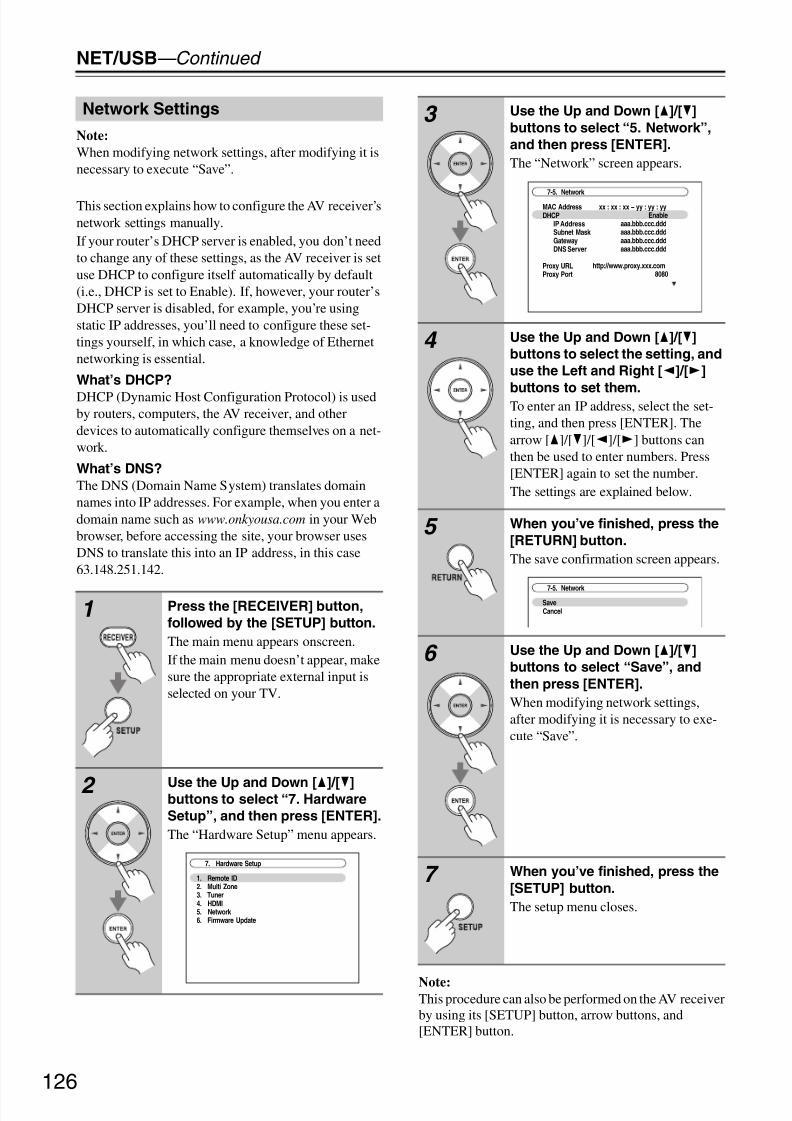
8/8/2019 Manual TX-NR5007 English
http://slidepdf.com/reader/full/manual-tx-nr5007-english 126/164126
NET/USB—Continued
Note:
When modifying network settings, after modifying it isnecessary to execute “Save”.
This section explains how to configure the AV receiver’snetwork settings manually.If your router’s DHCP server is enabled, you don’t needto change any of these settings, as the AV receiver is setuse DHCP to configure itself automatically by default(i.e., DHCP is set to Enable). If, however, your router’sDHCP server is disabled, for example, you’re usingstatic IP addresses, you’ll need to configure these set-tings yourself, in which case, a knowledge of Ethernetnetworking is essential.
What’s DHCP?
DHCP (Dynamic Host Configuration Protocol) is usedby routers, computers, the AV receiver, and otherdevices to automatically configure themselves on a net-work.
What’s DNS?
The DNS (Domain Name System) translates domainnames into IP addresses. For example, when you enter adomain name such as www.onkyousa.com in your Webbrowser, before accessing the site, your browser usesDNS to translate this into an IP address, in this case63.148.251.142.
Note:This procedure can also be performed on the AV receiverby using its [SETUP] button, arrow buttons, and[ENTER] button.
Network Settings
1 Press the [RECEIVER] button,
followed by the [SETUP] button.
The main menu appears onscreen.If the main menu doesn’t appear, makesure the appropriate external input isselected on your TV.
2 Use the Up and Down [q]/[w]buttons to select “7. Hardware
Setup”, and then press [ENTER].
The “Hardware Setup” menu appears.
7. Hardware Setup
1. Remote ID2. Multi Zone3. Tuner4. HDMI5. Network 6. Firmware Update
3 Use the Up and Down [q]/[w]
buttons to select “5. Network”,
and then press [ENTER].
The “Network” screen appears.
4 Use the Up and Down [q]/[w]
buttons to select the setting, and
use the Left and Right [e]/[r]
buttons to set them.To enter an IP address, select the set-ting, and then press [ENTER]. Thearrow [q]/[w]/[e]/[r] buttons canthen be used to enter numbers. Press[ENTER] again to set the number.The settings are explained below.
5 When you’ve finished, press the
[RETURN] button.
The save confirmation screen appears.
6 Use the Up and Down [q]/[w]
buttons to select “Save”, and
then press [ENTER].
When modifying network settings,after modifying it is necessary to exe-cute “Save”.
7 When you’ve finished, press the
[SETUP] button.
The setup menu closes.
7-5. Network
MAC AddressDHCP
IP AddressSubnet Mask GatewayDNS Server
Proxy URLProxy Port
xx : xx : xx − yy : yy : yyEnable
aaa.bbb.ccc.dddaaa.bbb.ccc.dddaaa.bbb.ccc.dddaaa.bbb.ccc.ddd
http://www.proxy.xxx.com8080
SaveCancel
7-5. Network

8/8/2019 Manual TX-NR5007 English
http://slidepdf.com/reader/full/manual-tx-nr5007-english 127/164127
NET/USB—Continued
Mac Address
This is the AV receiver’s MAC (Media Access Control)address. This address cannot be changed.
DHCP
This setting determines whether or not the AV receiveruses DHCP to automatically configure its IP Address,Subnet Mask, Gateway, and DNS Server settings.Enable: DHCP enabled.Disable: DHCP disabled.
If you select “Disable”, you must configure the “IPAddress”, “Subnet Mask”, “Gateway”, and “DNSServer” settings yourself.
IP Address
If you set the “DHCP” setting to “Disable”, you mustspecify an IP address. Enter a static IP address providedby your ISP.The IP address must be within the following ranges.Class A: 10.0.0.0 to 10.255.255.255Class B: 172.16.0.0 to 172.31.255.255Class C: 192.168.0.0 to 192.168.255.255Most routers use Class C IP addresses.
Subnet Mask
If you set the “DHCP” setting to “Disable”, you must
specify a subnet mask address.Enter the subnet mask address provided by your ISP(typically: 255.255.255.0).
Gateway
If you set the “DHCP” setting to “Disable”, you mustspecify a gateway address.Enter the gateway address provided by your ISP.
DNS Server
If you set the “DHCP” setting to “Disable”, you mustspecify a DNS server.Enter the DNS server addresses provided by your ISP.
Proxy URL
To use a Web proxy, enter its URL here.
Proxy Port
If you’re using a Web proxy, enter a proxy port numberhere.
Control This setting enables or disables control over the network. Enable: Control over the network enabled.Disable: Control over the network disabled.
Note:
When set to “Enable”, power consumption on standbymode slightly increases.
Port Number
This is the network port used for control over the net-
work.Note:
Set the port number between from “49152” to “65535”.
USB can be used to play music files stored on USB massstorage devices (e.g., USB flash drives and MP3 play-ers), which can be plugged into the AV receiver’s USBport.
Supported Audio File Formats
For USB mass storage device playback, the AV receiversupports music file formats.See “Supported Audio File Formats” on page 124.
USB Mass Storage Device Requirements
• The AV receiver supports USB devices that supportthe USB mass storage device class.
• Playback may not be possible with some USB deviceseven if they conform to the USB mass storage deviceclass.
• USB devices formatted with the FAT16 or FAT32 filesystem are supported.• If the storage device has been partitioned, each section
will be treated as an independent device.• Each folder may contain up to 20000 music files and
folders, and folders may be nested up to 16 levelsdeep.
• USB hubs and USB devices with hub functions are notsupported.
About USB

8/8/2019 Manual TX-NR5007 English
http://slidepdf.com/reader/full/manual-tx-nr5007-english 128/164128
NET/USB—Continued
This section explains how to play music files on a USBmass storage device.
Playing Music Files on a USB Device
1 Plug your USB mass storage
device into the AV receiver’s USB
port.
2 (TX-NR3007)
Press the [NET/USB] buttonrepeatedly to select the USB
screen.
(TX-NR5007)
Press the [NET/USB] button
repeatedly to select the
USB(Front) or USB(Rear) screen.
The USB indicator lights up if theAV receiver is able to read the USBmass storage device. The USB indica-tor flashes if the AV receiver cannotread the USB mass storage device.
NET/USB
qwer
ENTER
RECEIVER
1
1 / 1
USB(Front)
USB Storage
3 Use the Up and Down [q]/[w]
buttons to select a USB mass
storage device, and then press
[ENTER].
A list of the device’s contents appears.
To open a folder, use the Up and Down[q]/[w] buttons to select it, and thenpress [ENTER].
4
or
Use the Up and Down [q]/[w]
buttons to select a music file, and
press the [ENTER] or Play [1]
button to start playback.
Playback starts and the followingscreen appears.
To return to the previous menu duringplayback, press the [RETURN] button.To stop or pause playback, press theStop [2] or Pause [3] button, respec-tively.To select the next song, press the Next[6] button. To select the beginningof the current song, press the Previous
[7] button. To select the previoussong, press the Previous [7] buttontwice.To fast forward the current song, pressthe [4] button. To fast reverse thecurrent song, press the [5] button.
USB Storage
Folder1Folder201_Song_Track102_Song_Track203_Song_Track304_Song_Track405_Song_Track506_Song_Track607_Song_Track708_Song_Track8
2 / 5
00:10 01:12:34
Folder1
AlbumArtist02_Song_Track2
MP3 128kbps 16bit/44.1kHz
1/17
8/8/2019 Manual TX-NR5007 English
http://slidepdf.com/reader/full/manual-tx-nr5007-english 129/164129
NET/USB—Continued
Random Playback
The Random function can only be set while the PLAYscreen is displayed.To play songs in random order, while the list of songs isdisplayed, press the [RANDOM] button. All of the songsin the current folder will be played in random order.
When all of the songs in the folder have been playedonce, they’ll all be played again in a different randomorder. To cancel random playback, press the [RAN-DOM] button again.Random playback supports up to 20,000 songs perfolder. If a folder contains more than this, songs over20,000 are not included in random playback.
Repeat Playback
The Repeat function can only be set while the PLAYscreen is displayed.To play songs repeatedly, during playback (or while
playback is paused or stopped), press the [REPEAT] but-ton repeatedly to select: Repeat1, Repeat Folder, RepeatAll, or Off.In Repeat1 mode, the current song is played repeatedly.In Repeat Folder mode, all of the songs in the currentfolder are played repeatedly.In Repeat All mode, all of the songs on the USB massstorage device (in the same partition) are played repeat-edly.To cancel repeat playback, press the [REPEAT] buttonrepeatedly to select Off.
Notes:• If you connect a USB hard disk drive to theAV receiver’s USB port, we recommend that you useits AC adapter to power it.
• Do not connect the AV receiver’s USB port to a USBport on your computer. Music on your computer can-not be played through the AV receiver in this way.
• The AV receiver supports USB MP3 players that sup-port the USB Mass Storage Class standard, whichallows USB storage devices to be connected to com-puters without the need for special drivers or software.Note that not all USB MP3 players support the USB
Mass Storage Class standard. Refer your USB MP3player’s instruction manual for details.• Protected WMA music files on an MP3 player cannot
be played.
• Onkyo accepts no responsibility whatsoever for theloss or damage to data stored on a USB mass storagedevice when that device is used with the AV receiver.We recommend that you back up your importantmusic files beforehand.
• MP3 players containing music files that are managedwith special music software, and the iPod containingmusic files managed with iTunes are not supported.
• Operation with all USB mass storage devices includ-ing the ability to power them is not guaranteed.
• Do not connect your USB mass storage device via aUSB hub. The USB mass storage device must be con-nected directly to the AV receiver’s USB port.
• If the USB mass storage device contains a lot of data,the AV receiver make take a while to read it.
• USB memory devices with security functions cannotbe played.
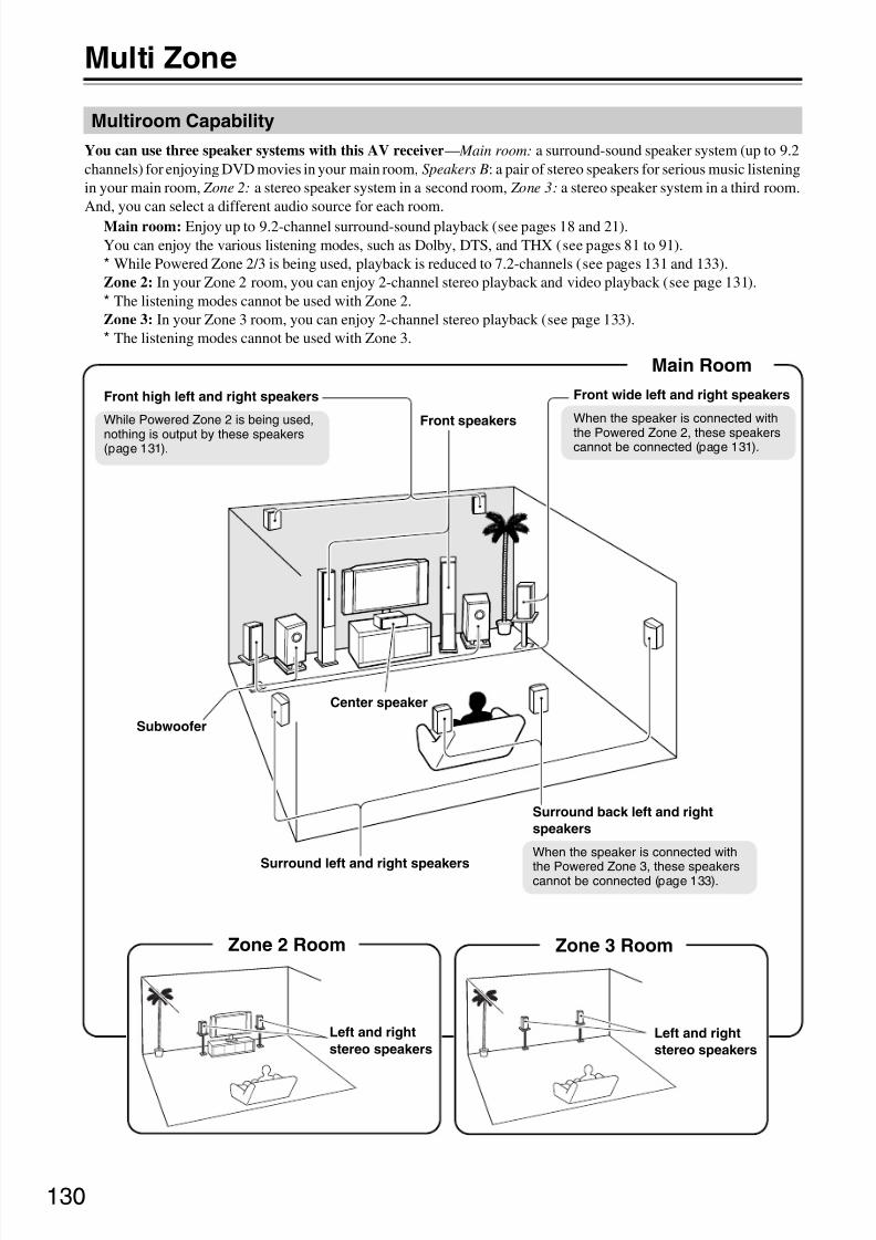
8/8/2019 Manual TX-NR5007 English
http://slidepdf.com/reader/full/manual-tx-nr5007-english 130/164130
Multi Zone
You can use three speaker systems with this AV receiver— Main room: a surround-sound speaker system (up to 9.2channels) for enjoying DVD movies in your main room, Speakers B: a pair of stereo speakers for serious music listeningin your main room, Zone 2: a stereo speaker system in a second room, Zone 3: a stereo speaker system in a third room.And, you can select a different audio source for each room.
Main room: Enjoy up to 9.2-channel surround-sound playback (see pages 18 and 21).You can enjoy the various listening modes, such as Dolby, DTS, and THX (see pages 81 to 91).* While Powered Zone 2/3 is being used, playback is reduced to 7.2-channels (see pages 131 and 133).Zone 2: In your Zone 2 room, you can enjoy 2-channel stereo playback and video playback (see page 131).* The listening modes cannot be used with Zone 2.Zone 3: In your Zone 3 room, you can enjoy 2-channel stereo playback (see page 133).* The listening modes cannot be used with Zone 3.
Multiroom Capability
Surround back left and right
speakers
When the speaker is connected with
the Powered Zone 3, these speakerscannot be connected (page 133).
Main Room
Front speakers
Center speaker
Subwoofer
Zone 2 Room
Left and right
stereo speakers
Front wide left and right speakers
When the speaker is connected with
the Powered Zone 2, these speakerscannot be connected (page 131).
Zone 3 Room
Left and right
stereo speakers
Surround left and right speakers
Front high left and right speakers
While Powered Zone 2 is being used,
nothing is output by these speakers(page 131).

8/8/2019 Manual TX-NR5007 English
http://slidepdf.com/reader/full/manual-tx-nr5007-english 131/164131
Multi Zone—Continued
In addition to your main listening room, you can also enjoy playback in the other room, or as we call Multi Zone. And,you can select a different source for each room.
There are two ways you can connect Zone 2 speakers:
1. Connect them directly to the AV receiver.2. Connect them to an amp in Zone 2.
Connecting Your Zone 2 Speakers Directly
to the AV receiver
This setup allows 7.2-channel playback in your mainroom and 2-channel stereo playback in Zone 2, with adifferent source in each room. This is called PoweredZone 2, as the Zone 2 speakers are powered by the AVreceiver. Note that when Powered Zone 2 is turned off,you can enjoy 9.2-channel playback in your main room.
Hookup
• Connect your Zone 2 speakers to the AV receiver’sFRONT WIDE/ZONE 2 L/R speaker terminals.
Notes:
• With this setup, the Zone 2 volume is controlled by theAV receiver.
• Powered Zone2 cannot be used if “SpeakersType(FrontB)” is set to “Normal”, “Bi-Amp” or“BTL” (see page 57).
Connecting Your Zone 2 Speakers to an
Amp in Zone 2
This setup allows 9.2-channel playback in your main lis-tening room and 2-channel stereo playback in Zone 2,with a different source in each room.
Hookup
• Use an RCA audio cable to connect the AV receiver’sZONE 2 PRE OUT L/R jacks to an analog audio inputon your Zone 2 amp.
• Connect your Zone 2 speakers to the speaker terminalson your Zone 2 amp.
Note:
With the default settings, the Zone 2 volume must be seton the Zone 2 amp. If your Zone 2 amp has no volume
control, set the “Zone2 Out” setting to “Variable” so thatyou can set the Zone 2 volume on the AV receiver (seepage 135).
Connecting Zone 2
To use this setup, you must set the “Powered Zone2”setting to “Act” (see page 134).
LR
Main room
Zone 2
TV
AV receiverR L
IN
R L
Main room
TV
Zone 2
AV receiver
Receiver/
integrated amp

8/8/2019 Manual TX-NR5007 English
http://slidepdf.com/reader/full/manual-tx-nr5007-english 132/164132
Multi Zone—Continued
Zone 2 Video Output
The AV receiver features a composite video output forconnection to a TV in Zone 2, so you can enjoy bothaudio and video in that zone.
Hookup
• Use a composite video cable to connect the AVreceiver’s ZONE 2 OUT V jack to a composite videoinput on your Zone 2 TV.
Note:
The ZONE 2 OUT V jack outputs video from compo-nents connected to composite video only.
Zone 2 12V Trigger
When Zone 2 is turned on, the output from the 12VTRIGGER OUT ZONE 2 goes high (+12 volts, 150 mil-liamperes max). Connecting this jack to a 12-volt triggerinput on a component in Zone 2 will make that compo-nent turn on or off as and when Zone 2 is turned on or off
on the AV receiver.
Main room
TV
Zone 2
AV receiver
TV

8/8/2019 Manual TX-NR5007 English
http://slidepdf.com/reader/full/manual-tx-nr5007-english 133/164133
Multi Zone—Continued
There are two ways you can connect Zone 3 speakers:1. Connect them directly to the AV receiver.2. Connect them to an amp in Zone 3.
Connecting Your Zone 3 Speakers Directly
to the AV receiver
This setup allows 7.2-channel playback in your mainroom and 2-channel stereo playback in Zone 3, with adifferent source in each room. This is called PoweredZone 3, as the Zone 3 speakers are powered by the AVreceiver. Note that when Powered Zone 3 is turned off,you can enjoy 9.2-channel playback in your main room.
Hookup
• Connect your Zone 3 speakers to the AV receiver’sSURR BACK/ZONE 3 L/R speaker terminals.
Notes:
• With this setup, the Zone 3 volume is controlled by theAV receiver.
• Powered Zone3 cannot be used if “SpeakersType(FrontA)” or “Speakers Type(FrontB)” is set to“Bi-Amp” or “BTL” (see page 57).
Connecting Your Zone 3 Speakers to an
Amp in Zone 3
This setup allows 9.2-channel playback in your main lis-tening room and 2-channel stereo playback in Zone 3,with a different source in each room.
Hookup• Use an RCA audio cable to connect the AV receiver’s
ZONE 3 PRE OUT L/R jacks to an analog audio inputon your Zone 3 amp.
• Connect your Zone 3 speakers to the speaker terminalson your Zone 3 amp.
Note:
With the default settings, the Zone 3 volume must be seton the Zone 3 amp. If your Zone 3 amp has no volumecontrol, set the “Zone3 Out” setting to “Variable” so thatyou can set the Zone 3 volume on the AV receiver (seepage 135).
Zone 3 12V Trigger
When Zone 3 is turned on, the output from the 12VTRIGGER OUT ZONE 3 goes high (+12 volts, 25 mil-liamperes max). Connecting this jack to a 12-volt triggerinput on a component in Zone 3 will make that compo-nent turn on or off as and when Zone 3 is turned on or off on the AV receiver.
Connecting Zone 3
To use this setup, you must set the “Powered Zone3”
setting to “Act” (see page 134).
LR
Main room
Zone 3
TV
AV receiverR L
IN
LR
Main room
TV
Zone 3
AV receiver
Receiver/ integrated amp

8/8/2019 Manual TX-NR5007 English
http://slidepdf.com/reader/full/manual-tx-nr5007-english 134/164134
Multi Zone—Continued
If you’ve connected your Zone 2/3 speakers to the AVreceiver, as explained in “Connecting Your Zone 2Speakers Directly to the AV receiver” on page 131 or“Connecting Your Zone 3 Speakers Directly to the AVreceiver” on page 133, you must set the “PoweredZone2” or “Powered Zone3” setting to “Act” (Acti-vated).
Notes:
• Powered Zone2 cannot be used if “SpeakersType(FrontB)” setting set to “Normal”, “Bi-Amp” or“BTL” (see page 58).
• Powered Zone3 cannot be used if “SpeakersType(FrontA)” or “Speakers Type(FrontB)” settingset to “Bi-Amp” or “BTL” (see page 58).
• This procedure can also be performed on the AV
receiver by using its [SETUP] button, arrow buttons,and [ENTER] button.
Setting the Powered Zone 2/3
1 Press the [RECEIVER] button
followed by the [SETUP] button.
The main menu appears onscreen.If the main menu doesn’t appear, makesure the appropriate external input isselected on your TV.
2 Use the Up and Down [q]/[w]
buttons to select “2. Speaker
Setup”, and then press [ENTER].
The “Speaker Setup” menu appears.
3 Use the Up and Down [q]/[w]
buttons to select “1. Speaker
Settings”, and then press
[ENTER].
The “Speaker Settings” menu appears.
2. Speaker Setup
1. Speaker Settings2. Speaker Configuration3. Speaker Distance4. Level Calibratio n5. Equalizer Settings
6. THX Audio Setup
2–1. Speaker Settings
Speaker ImpedanceSpeakers Type(FrontA)Speakers Type(FrontB)Powered Zone2Powered Zone3
6ohmsNormal
Not UseNot ActNot Act
4 Use the Up and Down [q]/[w]
buttons to select “Powered
Zone2” or “Powered Zone3”, and
use the Left and Right [e]/[r]
buttons to select:
Not Act:ZONE 2/3 L/R speaker terminalsnot activated (Powered Zone 2/3disabled).
Act:
ZONE 2/3 L/R speaker terminalsactivated (Powered Zone 2/3enabled).
5 Press the [SETUP] button.
The setup menu closes.

8/8/2019 Manual TX-NR5007 English
http://slidepdf.com/reader/full/manual-tx-nr5007-english 135/164135
Multi Zone—Continued
Note:
This procedure can also be performed on the AV receiverby using its [SETUP] button, arrow buttons, and[ENTER] button.
Zone2/3 Out
If you’ve connected your Zone 2/3 speakers to an ampwith no volume control, set the “Zone2 Out” and “Zone3Out” setting, respectively, to “Variable” so that you canset the volume, balance, and tone of zone 2/3 on the AVreceiver.
Zone2/3 Maximum Volume
With this setting, you can limit the maximum volume forZone 2/3. When the “Volume Display” setting is set to“Absolute”, the “Maximum Volume” range is 50 to 99.When it’s set to “Relative”, the range is –32 dB to+17 dB. To disable this setting, select “Off”.
Zone2/3 Power On Volume
This setting determines what the volume will be forZone 2/3 each time the AV receiver is turned on.When the “Volume Display” preference is set to “Abso-lute”, the range is “Last”, “Min”, 1 to 99, or “Max”.When it’s set to “Relative”, the range is “Last”, –Q dB,–81 dB to +18 dB.To use the same volume level as when the AV receiverwas last turned off, select “Last”.The “Zone2/3 Power On Volume” cannot be set higherthan the “Zone2/3 Maximum Volume” setting.
Setting the Multi Zone
1 Press the [RECEIVER] button
followed by the [SETUP] button.
The main menu appears onscreen.
If the main menu doesn’t appear, makesure the appropriate external input isselected on your TV.
2 Use the Up and Down [q]/[w]
buttons to select “7. Hardware
Setup”, and then press [ENTER].
The “Hardware Setup” menu appears.
3 Use the Up and Down [q]/[w]
buttons to select “2. Multi Zone”,
and then press [ENTER].
The “Multi Zone” menu appears.
4 Use the Up and Down [q]/[w]
buttons to select an item, and
use the Left and Right [e]/[r]buttons to change it.
The items are explained below.
7. Hardware Setup
1. Remote ID2. Multi Zone3. Tuner4. HDMI5. Network 6. Firmware Update
Zone2 Out
Zone2 Maximum Volume
Zone2 Power On Volume
Zone3 Out
Zone3 Maximum Volume
Zone3 Power On Volume
Fixed
Off
Last
Fixed
Off
Last
7–2. Multi Zone
5 When you’ve finished, press the
[SETUP] button.
The setup menu closes.
Fixed: The Zone 2/3 volume must be set on theamp in that zone (default).
Variable: The Zone 2/3 volume can be set on the AVreceiver.

8/8/2019 Manual TX-NR5007 English
http://slidepdf.com/reader/full/manual-tx-nr5007-english 136/164136
Multi Zone—Continued
This section explains how to turn Zone 2/3 on and off,how to select an input source for Zone 2/3, and how toadjust the volume for Zone 2/3.
Controlling Zone 2/3 from the AV receiver
Note:
When Zone 2/3 is turned off, the output from the 12VTRIGGER OUT ZONE 2/3 goes low (0 volts).
Controlling Zone 2/3 with the Remote
Controller
Note:
To control Zone 2/3, you must press the remote control-ler’s [ZONE] button first.The ZONE button turns red while Zone 2 is on, andgreen while Zone 3 is on.
Using Zone 2/3
1 To turn on Zone 2/3 and select an
input source, press the [ZONE 2]
or [ZONE 3] button followed by
an input selector button within 8
seconds.
Zone 2/3 turns on, the ZONE 2/3 indi-cator lights up.
Tip:
The 12V TRIGGER OUT ZONE 2/3goes high (+12 V).
To select AM or FM press the[TUNER] input selector and the[ZONE 2] or [ZONE 3] button repeat-edly. You can also select SIRIUS(North American models).
To select the same source as that of themain room, press the [ZONE 2] or[ZONE 3] button twice. “Zone 2 Selec-
tor: Source” or “Zone 3 Selector:Source” appears on the display.
2 To turn off Zone 2/3, press the
[ZONE 2] or [ZONE 3] button.
The ZONE 2 or ZONE 3 indicatorflashes.Press the [OFF] button.
The zone is turned off, and the ZONE 2or ZONE 3 indicator goes off.
ZONE 3ZONE 2 OFF
ZONE 2 indicator
ZONE 3 indicator
Input selector buttons 1 Press the [ZONE] buttonrepeatedly, then point the remote
controller at the AV receiver and
press the [ON] button.
Tip:
The 12V TRIGGER OUT ZONE 2/3goes high (+12 V).
2 To select an input source forZone 2/3, press the [ZONE]
button repeatedly, followed by an
INPUT SELECTOR button.
To select AM or FM press the[TUNER] INPUT SELECTOR and the[ZONE] button repeatedly. You canalso select SIRIUS (North American
models).
3 To turn off Zone 2/3, press the
[ZONE] button repeatedly,
followed by the [STANDBY]
button.
INPUTSELECTOR
ON ZONE
STANDBY
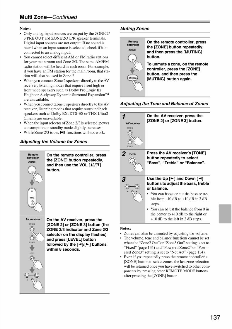
8/8/2019 Manual TX-NR5007 English
http://slidepdf.com/reader/full/manual-tx-nr5007-english 137/164137
Multi Zone—Continued
Notes:
• Only analog input sources are output by the ZONE 2/ 3 PRE OUT and ZONE 2/3 L/R speaker terminals.Digital input sources are not output. If no sound isheard when an input source is selected, check if it’sconnected to an analog input.
• You cannot select different AM or FM radio stationsfor your main room and Zone 2/3. The same AM/FMradio station will be heard in each room. For example,if you have an FM station for the main room, that sta-tion will also be used in Zone 2.
• When you connect Zone 2 speakers directly to the AVreceiver, listening modes that require front high orfront wide speakers such as Dolby Pro Logic IIzHeight or Audyssey Dynamic Surround Expansion™are unavailable.
• When you connect Zone 3 speakers directly to the AVreceiver, listening modes that require surround back
speakers such as Dolby EX, DTS-ES or THX Ultra2Cinema are unavailable.• When the input selector of Zone 2/3 is selected, power
consumption on standby mode slightly increases.• While Zone 2/3 is on,u functions will not work.
Adjusting the Volume for Zones
Muting Zones
Adjusting the Tone and Balance of Zones
Notes:
• Zones can also be unmuted by adjusting the volume.• The volume, tone and balance functions cannot be set
when the “Zone2 Out” or “Zone3 Out” setting is set to“Fixed” (page 135) and “Powered Zone2” or “Pow-ered Zone3” setting is set to “Not Act” (page 134).
• Even if you repeatedly press the remote controller’s[ZONE] button to select zones, the last zone selectionwill be retained once you have switched to other com-ponents by pressing other REMOTE MODE buttonsafter pressing the [ZONE] button.
Remotecontroller
On the remote controller, press
the [ZONE] button repeatedly,
and then use the VOL [q]/[w]
button.
AV receiver On the AV receiver, press the
[ZONE 2] or [ZONE 3] button (the
ZONE 2/3 indicator and Zone 2/3selector on the display flashes)
and press [LEVEL] button
followed by the [e]/[r] buttons
within 8 seconds.
Remotecontroller
On the remote controller, press
the [ZONE] button repeatedly,
and then press the [MUTING]
button.To unmute a zone, on the remote
controller, press the [ZONE]
button, and then press the
[MUTING] button again.
1AV receiver
On the AV receiver, press the[ZONE 2] or [ZONE 3] button.
2 Press the AV receiver’s [TONE]
button repeatedly to select
“Bass”, “Treble” or “Balance”.
3 Use the Up [r] and Down [e]
buttons to adjust the bass, treble
or balance.
• You can boost or cut the bass or tre-ble from –10 dB to +10 dB in 2 dBsteps.
• You can adjust the balance from 0 inthe center to +10 dB to the right or+10 dB to the left in 2 dB steps.

8/8/2019 Manual TX-NR5007 English
http://slidepdf.com/reader/full/manual-tx-nr5007-english 138/164138
Multi Zone—Continued
To control the AV receiver with the remote controllerwhile you’re in Zone 2 or Zone 3, you’ll need a commer-
cially available multiroom remote control kit for eachzone.• Multiroom kits are made by Niles and Xantech.These kits can also be used when there isn’t a clear lineof sight to the AV receiver’s remote sensor, such as whenit’s installed inside a cabinet.
Using a Multiroom Kit with Zone 2/3
In this setup, the IR receiver in Zone 2/3 picks up theinfrared signals from the remote controller and feedsthem through to the AV receiver in the main room via theconnecting block.
The miniplug cable from the connecting block should beconnected to the AV receiver’s IR IN jack, as shownbelow.
Using a Multiroom Kit with a Cabinet
In this setup, the IR receiver picks up the infrared signalsfrom the remote controller and feeds them to the AVreceiver located in the cabinet via the connecting block.
Using a Multiroom Kit with Other
Components
In this setup, an IR emitter is connected to the AVreceiver’s IR OUT jack and placed in front of the othercomponent’s remote control sensor. Infrared signalsreceived at the AV receiver’s IR IN jack are fed throughto the other component via the IR emitter. Signals pickedup by the AV receiver’s remote control sensor are notoutput.
The IR emitter should be connected to the AV receiver’sIR OUT jack, as shown below.
Using the Remote Controller in Zone2/3 and Multiroom Control Kits
IR IN
Connectingblock
Remote controller
IR receiver
Main room Zone 2/3
Signal flow
From the connecting block
Miniplug cable
AV receiver
Signal flow
IR IN
Connectingblock
Remote controller
IR receiver
Insidecabinet
Signal flow
IR IN
IR OUT
Connectingblock
IR receiver
Remote controller
Signal flow
IR Emitter
Other component
AV receiver
Remote controlsensor
Other component
Emitter
IR Emitter
Signal flow
Miniplug
Miniplug cable
AV receiver

8/8/2019 Manual TX-NR5007 English
http://slidepdf.com/reader/full/manual-tx-nr5007-english 139/164139
Controlling Other Components
You can use the AV receiver’s remote controller(RC-747M) to control your other AV components,including those made by other manufacturers. This sec-tion explains how to enter the remote control code for acomponent that you want to control: DVD, TV, VCR,etc.• Learn commands directly from another component’s
remote controller (see page 152).• Program the ACTIVITIES buttons to perform a
sequence of up to 32 remote control actions (seepage 153).
The following REMOTE MODE buttons are prepro-grammed with remote control codes for controlling the
components listed. You do not need to enter a remotecontrol code to control these components.For details on controlling these components, see thepages indicated.
You can look up for appropriate remote control codefrom onscreen setup menu.
Note:
This setting can be carried out by using Onscreen SetupMenu only.
Preprogrammed Remote ControlCodes
Onkyo DVD player (page 144)
Onkyo CD player (page 147)
Onkyo cassette recorder withu (page 149)
SETUP
RECEIVER
qwer
ENTER
Looking up for Remote Control Code
1 Press the [RECEIVER] button fol-
lowed by the [SETUP] button.
The main menu appears onscreen.If the main menu doesn’t appear, makesure the appropriate external input isselected on your TV.
2 Use the Up and Down [q]/[w] but-
tons to select “8. Remote Con-
troller Setup”, and then press
[ENTER].
3 Use the Up and Down [q]/[w] but-
tons to select “1. Remote Mode
Setup”, and then press [ENTER].
4 Use the Up and Down [q]/[w] but-
tons to select remote mode, and
then press [ENTER].
The category selection menu appears.
1. Remote Mode Setup2. Activities Setup
8. Remote Controller Setup
TVDVD/BDVCR/DVRCBL/SATGAMEAUX 1
AUX 2TV/TAPECDPHONO
8–1. Remote Mode Setup
TVTV/DVDTV/VCR
8–1. Remote Mode Setup TV

8/8/2019 Manual TX-NR5007 English
http://slidepdf.com/reader/full/manual-tx-nr5007-english 140/164140
Controlling Other Components—Continued
5 Use the Up and Down [q]/[w] but-
tons to select category, and then
press [ENTER].
The brand name input panel appears.
6 Use the arrow [q]/[w]/[e]/[r] but-
tons to select a character, and
then press [ENTER].
Repeat this step from the 1st characterto the 3rd character of the brand name.When you have entered the 3rd charac-ter, select “Search” and press[ENTER].After searching, a list of the brandname appears.
If the brand name is not found:
Use the Right [r] button to select
“Not Listed”, and then press
[ENTER].
The brand name input panel appears.
7 Use the Up and Down [q]/[w] but-
tons to select brand, and thenpress [ENTER].
After searching is completed, a mes-sage for remote control code transferwill appear.
A B C D E F G H I J K L M
N O P Q R S T U V W X Y Z
1 2 3 4 5 6 7 8 9 0 & @–
Space Back Space Search
8–1. Remote Mode SetupTV
CategoryBrand
TV
Not Listed
Sonawa
SonberSongbaSonicSoniko
8–1. Remote Mode Setup TV
CategoryBrand
TVSON
8–1. Remote Mode Setup TV
CategoryBrand
TVXXXXX
OK
Now we are ready to transfer data to Remote
Please hold remote so that it is facing the receiver.
Use ENTER button of your remote to activate “OK”.
Ready?
To use the remote controller, point it atthe AV receiver’s remote control sen-sor, as shown below.
On the remote controller press the[ENTER] button.
When the transfer is successful, the fol-lowing screen appears. Try it.
* When category other than TV have beenselected, the content is different.
8 If you can control component,
press the [RECEIVER] button,
use the Up and Down [q]/[w] but-
tons to select “Works”, and then
press [ENTER].
The “Remote Mode Setup” menuappears.
If you cannot control component,
use the Up and Down [q]/[w] but-
tons to select “Doesn’t work (try
next Code)” and press [ENTER].
The next code is appear.
9 When you’ve finished, press the
[SETUP] button.
The setup menu closes.
15
15
AV receiver
Approx.
16ft. (5 m)
Incoming sensor
Transmitter
15° off center
(Left/Right/Up/Down)
CategoryBrand
TVXXXXX
8–1. Remote Mode Setup TV
Wait
8–1. Remote Mode Setup TV
CategoryBrand
TVXXXXX
WorksDoesn’t work (try next Code)
1. Push remote Mode [TV].
2. Push some key to see if the TV responds.
3. Push remote Mode [RECEIVER].
4. Choose “Works” or “Doesn’t work”.

8/8/2019 Manual TX-NR5007 English
http://slidepdf.com/reader/full/manual-tx-nr5007-english 141/164141
Controlling Other Components—Continued
You’ll need to enter a code for each component that youwant to control.
Note:
The remote control codes provided are correct at the timeof printing, but are subject to change.
Entering Remote Control Codes
REMOTEMODE
DISPLAY
Number
buttons
1 Look up the appropriate remote
control code in the separate
Remote Control Codes list.
The codes are organized by category(e.g., DVD player, TV, etc.).
2
(3 seconds)
While holding down the REMOTE
MODE button to which you want
to enter a code, press and hold
down the [DISPLAY] button
(about 3 seconds).
The REMOTE MODE button lights up.
Notes:
• Remote control codes cannot beentered for the [RECEIVER] and[ZONE] buttons.
• Only TV remote control codes can beentered for the [TV] button.• Except for the [RECEIVER], [TV],
and [ZONE] buttons, remote controlcodes from any category can beentered for the REMOTE MODEbuttons. However, these buttons alsowork as input selector buttons(page 67), so choose a REMOTEMODE button that corresponds withthe input to which you connect yourcomponent. For example, if you con-nect your CD player to the CD input,choose the [CD] button when enter-ing its remote control code.
3 Within 30 seconds, use the num-
ber buttons to enter the 5-digit
remote control code.
The REMOTE MODE button flashestwice.If the remote control code is not enteredsuccessfully, the REMOTE MODEbutton will flash once slowly.
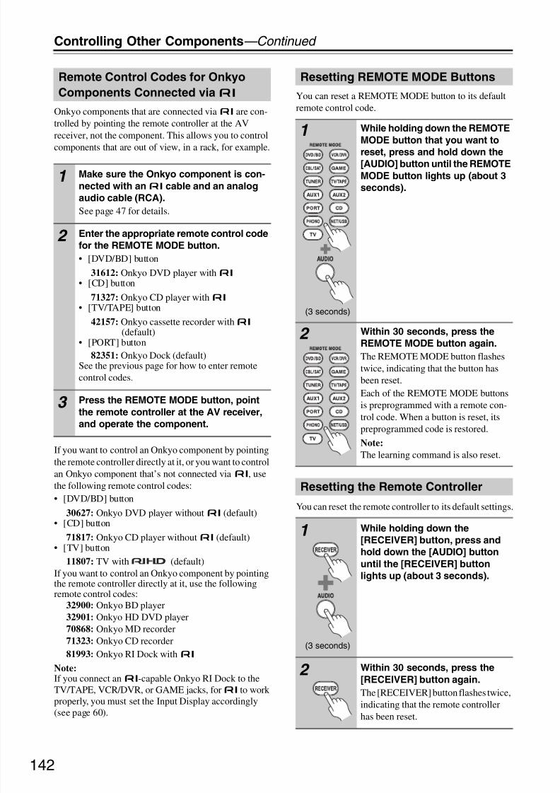
8/8/2019 Manual TX-NR5007 English
http://slidepdf.com/reader/full/manual-tx-nr5007-english 142/164142
Controlling Other Components—Continued
Onkyo components that are connected viau are con-trolled by pointing the remote controller at the AV
receiver, not the component. This allows you to controlcomponents that are out of view, in a rack, for example.
If you want to control an Onkyo component by pointingthe remote controller directly at it, or you want to controlan Onkyo component that’s not connected viau, usethe following remote control codes:• [DVD/BD] button
30627: Onkyo DVD player withoutu (default)• [CD] button
71817: Onkyo CD player withoutu (default)• [TV] button
11807: TV with (default)If you want to control an Onkyo component by pointingthe remote controller directly at it, use the followingremote control codes:
32900: Onkyo BD player32901: Onkyo HD DVD player70868: Onkyo MD recorder71323: Onkyo CD recorder81993: Onkyo RI Dock withu
Note:If you connect anu-capable Onkyo RI Dock to the
TV/TAPE, VCR/DVR, or GAME jacks, foru
to workproperly, you must set the Input Display accordingly(see page 60).
You can reset a REMOTE MODE button to its defaultremote control code.
You can reset the remote controller to its default settings.
Remote Control Codes for Onkyo
Components Connected viau
1 Make sure the Onkyo component is con-
nected with anu cable and an analog
audio cable (RCA).
See page 47 for details.
2 Enter the appropriate remote control code
for the REMOTE MODE button.
• [DVD/BD] button
31612: Onkyo DVD player withu
• [CD] button
71327: Onkyo CD player withu• [TV/TAPE] button
42157: Onkyo cassette recorder withu (default)
• [PORT] button82351: Onkyo Dock (default)
See the previous page for how to enter remotecontrol codes.
3 Press the REMOTE MODE button, point
the remote controller at the AV receiver,and operate the component.
Resetting REMOTE MODE Buttons
1
(3 seconds)
While holding down the REMOTE
MODE button that you want toreset, press and hold down the
[AUDIO] button until the REMOTE
MODE button lights up (about 3
seconds).
2 Within 30 seconds, press the
REMOTE MODE button again.
The REMOTE MODE button flashestwice, indicating that the button hasbeen reset.Each of the REMOTE MODE buttonsis preprogrammed with a remote con-
trol code. When a button is reset, itspreprogrammed code is restored.
Note:
The learning command is also reset.
Resetting the Remote Controller
1
(3 seconds)
While holding down the
[RECEIVER] button, press and
hold down the [AUDIO] buttonuntil the [RECEIVER] button
lights up (about 3 seconds).
2 Within 30 seconds, press the
[RECEIVER] button again.
The [RECEIVER] button flashes twice,indicating that the remote controllerhas been reset.

8/8/2019 Manual TX-NR5007 English
http://slidepdf.com/reader/full/manual-tx-nr5007-english 143/164143
Controlling Other Components—Continued
By pressing the [TV] button that’s been programmedwith the remote control code for TV, you can controlyour TV with the following buttons.For details on entering a remote control code for a differ-ent component, see page 141.The [TV] button is preprogrammed with the remote con-trol code for controlling a TV that supports the
*1 (limited to some models). The TV must beable to receive remote control commands viaand be connected to the AV receiver via HDMI. If con-trolling your TV via doesn’t work very well,program your TV’s remote control code into the [TV]button and use the TV remote mode to control your TV.
a ON, STANDBY, TV [9] buttons
Set the TV to On or Standby.
b TV VOL [q]/[w] button
Adjust the TV’s volume.c TV [INPUT] button
Selects the TV’s external inputs.
d GUIDE button
Displays the program guide.
e Arrow [q]/[w]/[e]/[r] and ENTER buttons
Used to navigate menus and select items.
f SETUP button
Displays a menu.
g [1], [3], [2], [5], [4], [7], [6]
buttons*
Play, Pause, Stop, Fast reverse, Fast forward, Previ-ous, and Next.These buttons works for combination devices.
h SEARCH, REPEAT, RANDOM, and PLAY
MODE buttons
Function as colored buttons or A, B, C, D buttons.
i Number buttons
Enter numbers. 0 button enters 11 on some compo-nents. +10 button* works as “--/---” button or +10.
j DISPLAY button
Displays information.k MUTING button
Mutes the TV.
l CH +/– button
Select channels on the TV.
m PREV CH button
Selects the previous or last channel.
n RETURN button
Exits the TV’s setup menu.
o AUDIO button*
Selects foreign language soundtracks and audio for-mats (e.g., Dolby Digital or DTS).
p CLR button
Cancels functions and clears entered numbers, orenters 12.
Notes:
• With some components, certain buttons may not workas expected, and some may not work at all.
• Buttons marked with an asterisk (*) are not supportedby the function.
Controlling a TV
p
o
n
k
j
m
l
i
g
h
f
a
d
b
e
a
c
Press [TV] button first.
*1 The supported by the AV receiver is the CECsystem control function of the HDMI standard.

8/8/2019 Manual TX-NR5007 English
http://slidepdf.com/reader/full/manual-tx-nr5007-english 144/164144
Controlling Other Components—Continued
By pressing the REMOTE MODE button that’s beenprogrammed with the remote control code for your DVDplayer (HD DVD, Blu-ray, or TV/DVD combination),you can control your player with the following buttons.
The [DVD/BD] button is preprogrammed with theremote control code for controlling an Onkyo DVDplayer.For details on entering a remote control code for a differ-ent component, see page 141.The [DVD/BD] button is preprogrammed with theremote control code for controlling a component thatsupports the *1. The component must be able toreceive remote control commands via and beconnected to the AV receiver via HDMI. If controllingyour component via doesn’t work very well,program your component’s remote control code into the[DVD/BD] button and use the DVD/BD remote mode tocontrol your component.
*1 The supported by the AV receiver is the CEC systemcontrol function of the HDMI standard.
*2 When you want to change the remote controller mode withoutchanging the current input source, press the [MODE] button andwithin about eight seconds, press the REMOTE MODE button.Then, with the AV receiver’s remote controller, you can controlthe component corresponding to the button you pressed.
a ON, STANDBY buttons
Sets the DVD player to On or Standby.
b TV [9] button
Set the TV to On or Standby.
c TV [INPUT] button
Selects the TV’s external inputs.
d TV VOL [q]/[w] button
Adjust the TV’s volume.
e TOP MENU button
Displays a DVD’s top menu or a DVD’s title.
f Arrow [q]/[w]/[e]/[r] and ENTER buttonsUsed to navigate menus and select items.
g SETUP button
Used to access the DVD player’s settings.
h [1], [3], [2], [5], [4], [7], [6]
buttons
Play, Pause, Stop, Fast reverse, Fast forward, Previ-ous, and Next.
i REPEAT button
Used with the repeat playback functions.
j SEARCH button*
Used to search title, chapter, and track numbers, andto search times for locating specific points.
k Number buttons
Used to enter title, chapter, and track numbers, andto enter times for locating specific points. The [+10]button* works as a +10 button or “--/---” button.
l DISPLAY button
Displays information about the current disc, title,chapter, or track, including elapsed time, remainingtime, total time, and so on.
m MUTING button (69)
Mutes or unmutes the AV receiver.n CH +/–, DISC +/– button
Selects discs on a DVD changer. Selects TV chan-nels on a component with a built-in tuner.
o VOL [q]/[w] button (67)
Adjusts the volume of the AV receiver.
p MENU button
Displays a DVD’s menu.
q RETURN button
Exits the DVD player’s setup menu or returns to theprevious menu.
r AUDIO button*Selects foreign language soundtracks and audio for-mats (e.g., Dolby Digital or DTS).
s RANDOM button*
Used with the random playback function.
Controlling a DVD Player or DVD Recorder
u
r
q
t
s
m
l
p
o
k
h
j
i
g
b
*2
e
c
f
a
d
n
Press the appropriate
REMOTE MODE button first.

8/8/2019 Manual TX-NR5007 English
http://slidepdf.com/reader/full/manual-tx-nr5007-english 145/164145
Controlling Other Components—Continued
t PLAY MODE button*
Selects play modes on components with selectableplay modes.
u CLR button
Cancels functions and clears entered numbers.
Notes:• With some components, certain buttons may not workas expected, and some may not work at all.
• If you enter the remote control code for a HD DVD orBlu-ray player that has A, B, C, and D or colored but-tons, the [SEARCH], [REPEAT], [RANDOM], and[PLAY MODE] buttons will work as colored or A, B,C, D buttons. In this case, these buttons cannot be usedto set repeat playback, random playback, or select play
modes.• Buttons marked with an asterisk (*) are not supportedby the function.
By pressing the REMOTE MODE button that’s beenprogrammed with the remote control code for your VCR(TV/VCR, PVR, DBS/PVR combination or cable/PVRcombination), you can control your video recorder withthe following buttons.For details on entering a remote control code for a differ-ent component, see page 141.
a ON, STANDBY buttons
Set the video recorder to On or Standby.
b TV [9] button
Set the TV to On or Standby.
c TV [INPUT] button
Selects the TV’s external inputs.
d TV VOL [q]/[w] buttonAdjust the TV’s volume.
e GUIDE button
Displays the program guide or navigation list.
f Arrow [q]/[w]/[e]/[r] and ENTER buttons
Used to navigate menus and select items.
g SETUP button
Displays the video recorders setup menu.
h Previous [7] button
Previous or instant replay function.
i Number buttonsEnter numbers. The [0] button enters 11 on somecomponents. The [+10] button works as a +10 but-ton or “--/---” button.
j DISPLAY button
Displays information.
k MUTING button (69)
Mutes or unmutes the AV receiver.
l CH +/– button
Selects TV channels on the video recorder.
m VOL [q]/[w] button (67)
Adjusts the volume of the AV receiver.
n PREV CH button
Selects the previous channel.
o RETURN button
Exits the menu or returns to the previous menu.
p Next [6] button
Next or advance function.
q [1], [3], [2], [5], [4] buttons
Play, Pause, Stop, Fast reverse, and Fast forward.
r CLR button
Cancels functions or enters the number 12.Note:
With some components, certain buttons may not work asexpected, and some may not work at all.
Controlling a VCR or PVR
r
o
p
q
k
j
n
m
i
h
g
b
*1
e
c
f
a
d
l
Press the appropriate
REMOTE MODE button first.
*1 When you want to change the remote controller mode withoutchanging the current input source, press the [MODE] button andwithin about eight seconds, press the REMOTE MODE button.Then, with the AV receiver’s remote controller, you can controlthe component corresponding to the button you pressed.

8/8/2019 Manual TX-NR5007 English
http://slidepdf.com/reader/full/manual-tx-nr5007-english 146/164

8/8/2019 Manual TX-NR5007 English
http://slidepdf.com/reader/full/manual-tx-nr5007-english 147/164

8/8/2019 Manual TX-NR5007 English
http://slidepdf.com/reader/full/manual-tx-nr5007-english 148/164148
Controlling Other Components—Continued
By pressing the REMOTE MODE button that’s beenprogrammed with the remote control code for yourDock, you can control your iPod in the Dock with thefollowing buttons.
For some RI docks, the [ON], [STANDBY] button maynot work with a remote control code 82990 (withoutu).In this case, make anu connection and enter a remotecontrol code 81993 (withu).For details on entering a remote control code, seepage 141.When Using an RI Dock:
• When using the Onkyo DS-A3 RI Dock, make anu connection and enter a remote control code 81993 (withu).
• Connect the RI Dock to the TV/TAPE IN, VCR/DVR
IN, or GAME IN L/R jacks.• Set the RI Dock’s RI MODE switch to HDD or HDD/
DOCK.• Set the AV receiver’s Input Display to DOCK (see
page 60).• See to the Dock’s instruction manual for more infor-
mation.
a ON, STANDBY buttons
Turns the iPod on or off.
Notes:
• This button does not turn the Onkyo DS-A2 orDS-A2X RI Dock on or off.• Your iPod may not respond the first time you press this
button, in which case you should press it again. This isbecause the remote controller transmits the On andStandby commands alternately, so if your iPod isalready on, it will remain on when the remote control-ler transmits an On command. Similarly, if your iPodis already off, it will remain off when the remote con-troller transmits an Off command.
b TOP MENU button
Works as a Mode button when used with a DS-A2
RI Dock.c Arrow [q]/[w] and ENTER buttons
Used to navigate menus and select items.
d Previous [7] button
Restarts the current song. Press it twice to select theprevious song.
e Fast Reverse [5] button
Press and hold to fast reverse.
f Pause [3] button
Pauses playback.
gREPEAT buttonUsed with the repeat function.
h DISPLAY button
Turns on the backlight for 30 seconds.
i MUTING button (69)
Mutes or unmutes the AV receiver.
j ALBUM +/– button
Selects the next or previous album.
k VOL [q]/[w] button (67)
Adjusts the volume of the AV receiver.
l MENU button
Exits the menu.
m PLAYLIST [e]/[r] button
Selects the previous or next playlist on the iPod.
n Play [1] button
Starts playback. If the component is off, it will turnon automatically.
o Next [6] button
Selects the next song.
p Fast Forward [4] button
Press and hold to fast forward.
q Stop [2] buttonStops playback and displays a menu.
Controlling an RI Dock
h
k
j
n
l
o
p
q
r
m
b
c
a
i
d
f
e
g s
Press the appropriate
REMOTE MODE button first.

8/8/2019 Manual TX-NR5007 English
http://slidepdf.com/reader/full/manual-tx-nr5007-english 149/164149
Controlling Other Components—Continued
r PLAY MODE button
Selects play modes on components with selectableplay modes.Works as a Resume button when used with a DS-A2RI Dock.
s RANDOM button
Used with the shuffle function.
Note:
With some components, certain buttons may not work asexpected, and some may not work at all.
By pressing the REMOTE MODE button that’s beenprogrammed with the remote control code for your cas-sette recorder, you can control your cassette recorderwith the following buttons.The [TV/TAPE] button is preprogrammed with theremote control code for controlling an Onkyo cassetterecorder when used with anu connection.For details on entering a remote control code for a differ-ent component, see page 141.
On twin cassette decks, only Deck B can be controlled.
a ON, STANDBY buttons
Turns the cassette recorder on or off.
b Previous and Next [7]/[6] buttons
The Previous [7] button selects the previoustrack. During playback it selects the beginning of the current track. The Next [6] button selects thenext track.Depending on how they were recorded, the Previous
and Next [7]/[6] buttons may not work prop-erly with some cassette tapes.
c Fast Reverse and Fast Forward [5]/[4]
buttons
The Fast Reverse [5] button starts fast reverse.The Fast Forward [4] button starts fast forward.
d Reverse Play [t] button
Starts reverse playback.
e Play [1] button
Starts playback.
f MUTING button (69)
Mutes or unmutes the AV receiver.g VOL [q]/[w] button (67)
Adjusts the volume of the AV receiver.
h Stop [2] button
Stops playback.
Notes:
• An Onkyo cassette recorder connected viau canalso be controlled in Receiver mode.
• With some components, certain buttons may not workas expected, and some may not work at all.
Controlling a Cassette Recorder
h
c
g
b
e
f
d
bc
a
Press the appropriateREMOTE MODE button first.

8/8/2019 Manual TX-NR5007 English
http://slidepdf.com/reader/full/manual-tx-nr5007-english 150/164150
Controlling Other Components—Continued
Via onscreen menu, you can specify what actions will betaken by the Easy macro command in the Easy macromode.
Activities Setup
1 Press the [RECEIVER] button fol-
lowed by the [SETUP] button.
The main menu appears onscreen.If the main menu doesn’t appear, makesure the appropriate external input isselected on your TV.
2 Use the Up and Down [q]/[w] but-
tons to select “8. Remote Con-
troller Setup”, and then press
[ENTER].
The “Remote Controller Setup” menuappears.
3 Use the Up and Down [q]/[w] but-
tons to select “2. Activities
Setup”, and then press [ENTER].
The “Activities Setup” menu appears.
4 Use the Up and Down [q]/[w] but-
tons to select “My Movie”, “My
TV”, or “My Music”, and then
press [ENTER].
My Movie: Actions for the[MY MOVIE] button ischanged.
My TV: Actions for the [MY TV]
button is changed.My Music: Actions for the
[MY MUSIC] button ischanged.
1. Remote Mode Setup2. Activities Setup
8. Remote Controller Setup
My MovieMy TVMy Music
8–2. Activities Setup
5 Use the Up and Down [q]/[w] but-
tons to select an item, and use
the Left and Right [e]/[r] but-
tons to change the settings.
The items are explained below.
Source
DVD/BD, VCR/DVR, CBL/SAT,
GAME, AUX 1, AUX 2, TV/
TAPE, TUNER, CD, PHONO,
PORT, NET/USB
With this setting, you can choosethe input source.
TV Power On
Enable: TV to turn on “Enable”.Disable: TV to turn on “Disable”.
This option enables the TV to turnon when the ACTIVITIES button ispressed.
Source Power On
Enable: Source to turn on“Enable”.
Disable: Source to turn on“Disable”.
This option enables the Source toturn on when the ACTIVITIES but-ton is pressed.
Receiver Power On
Enable: AV receiver to turn on“Enable”.
Disable: AV receiver to turn on“Disable”.
This option enables the AV receiverto turn on when the ACTIVITIESbutton is pressed.
Receiver Source Change
Enable: AV receiver inputselector is change.
Disable: AV receiver inputselector is not change.
This option enables the AV receiverinput selector to change when theACTIVITIES button is pressed.
8–2. Activities Setup MY Movie
SourceTV Power ONSource Power ONReceiver Power ONReceiver Source ChangeSource Play
DVD/BDEnableEnableEnableEnableEnable

8/8/2019 Manual TX-NR5007 English
http://slidepdf.com/reader/full/manual-tx-nr5007-english 151/164151
Controlling Other Components—Continued
Here are the default settings.
Source Play
Enable: Start playback the sourceof “Enable”.
Disable: Start playback the sourceof “Disable”.
This option enables the Source tostart playback when the ACTIVI-TIES button is pressed.
Items
Default Settings
My
MovieMy TV
My
Music
Source DVD CBL CD
TV Power On Enable Enable Disable
Source Power On Enable Enable Enable
Receiver Power On Enable Enable Enable
Receiver Source
ChangeEnable Enable Enable
Source Play Enable Disable Enable
6 Press [ENTER].
A message for transfer will appear.
To use the remote controller, point it atthe AV receiver’s remote control sen-sor, as shown below.
8–2. Activities Setup My Movie
OK
Now we are ready to transfer data to Remote
Please hold remote so that it is facing the receiver.
Use ENTER button of your remote to activate “OK”.
Ready?
15
15
AV receiver
Approx.
16ft. (5 m)
Incoming sensor
Transmitter
15° off center
(Left/Right/Up/Down)
7 On the remote controller press
the [ENTER] button.
When the transfer is successful, the fol-lowing screen appears.
8 When you’ve finished, press the
[ENTER] button.
The “8-2. Activities Setup” menuappears onscreen.
9 When you’ve finished, press the[SETUP] button.
The setup menu closes.
8–2. Activities Setup My Movie
Wait
8–2. Activities Setup My Movie
Return
Successful

8/8/2019 Manual TX-NR5007 English
http://slidepdf.com/reader/full/manual-tx-nr5007-english 152/164
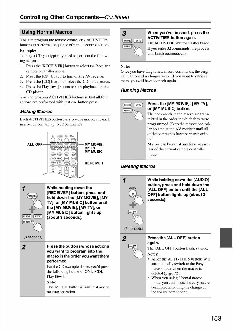
8/8/2019 Manual TX-NR5007 English
http://slidepdf.com/reader/full/manual-tx-nr5007-english 153/164153
Controlling Other Components—Continued
You can program the remote controller’s ACTIVITIESbuttons to perform a sequence of remote control actions.
Example:
To play a CD you typically need to perform the follow-ing actions:1. Press the [RECEIVER] button to select the Receiver
remote controller mode.2. Press the [ON] button to turn on the AV receiver.3. Press the [CD] button to select the CD input source.4. Press the Play [1] button to start playback on the
CD player.You can program ACTIVITIES buttons so that all fouractions are performed with just one button press.
Making Macros
Each ACTIVITIES button can store one macro, and eachmacro can contain up to 32 commands.
Note:
Once you have taught new macro commands, the origi-nal macro will no longer work. If you want to retrievethem, you will have to teach again.
Running Macros
Deleting Macros
Using Normal Macros
1
(3 seconds)
While holding down the
[RECEIVER] button, press and
hold down the [MY MOVIE], [MY
TV], or [MY MUSIC] button until
the [MY MOVIE], [MY TV], or
[MY MUSIC] button lights up
(about 3 seconds).
2 Press the buttons whose actions
you want to program into the
macro in the order you want them
performed.
For the CD example above, you’d pressthe following buttons: [ON], [CD],Play [1].
Note:
The [MODE] button is invalid at macromaking operation.
RECEIVER
MY MOVIE,MY TV,MY MUSIC
ALL OFF
3 When you’ve finished, press the
ACTIVITIES button again.
The ACTIVITIES button flashes twice.If you enter 32 commands, the processwill finish automatically.
Press the [MY MOVIE], [MY TV],
or [MY MUSIC] button.
The commands in the macro are trans-mitted in the order in which they wereprogrammed. Keep the remote control-ler pointed at the AV receiver until allof the commands have been transmit-ted.Macros can be run at any time, regard-less of the current remote controllermode.
1
(3 seconds)
While holding down the [AUDIO]
button, press and hold down the
[ALL OFF] button until the [ALL
OFF] button lights up (about 3
seconds).
2 Press the [ALL OFF] button
again.
The [ALL OFF] button flashes twice.
Notes:
• All of the ACTIVITIES buttons willautomatically switch to the Easymacro mode when the macro isdeleted (page 72).
• When you using Normal macromode, you cannot use the easy macro
command including the change of the source component.

8/8/2019 Manual TX-NR5007 English
http://slidepdf.com/reader/full/manual-tx-nr5007-english 154/164154
Troubleshooting
If you have any trouble using the AV receiver, look for asolution in this section. If you can’t resolve the issueyourself, contact your Onkyo dealer.
Can’t turn on the AV receiver
• Make sure that the power cord is properly plugged intothe wall outlet.
• Unplug the power cord from the wall outlet, wait fiveseconds or more, then plug it in again.
The AV receiver turns off as soon as it’s turned
on
• The amp protection circuit has been activated.Remove the power cord from the wall outlet immedi-ately. Disconnect all speaker cables and input sources,and leave the AV receiver with its power cord discon-nected for 1 hour. After that, reconnect the power cordand set the volume to maximum. If the AV receiverstays on, set the volume to minimum, disconnect thepower cord, and reconnect your speakers and inputsources. If the AV receiver turns off when you set thevolume to maximum, disconnect the power cord, andcontact your Onkyo dealer.
There’s no sound, or it’s very quiet
• Make sure that the digital input source is selectedproperly (page 56).
• Make sure that all audio connecting plugs are pushedin all the way (page 29).
• Make sure that the inputs and outputs of all compo-nents are connected properly (pages 31 to 46).
• Make sure that the polarity of the speaker cables iscorrect, and that the bare wires are in contact with themetal part of each speaker terminal (page 20).
• Make sure that the input source is properly selected(page 67).
• Make sure that the speaker cables are not shorting.• Check the volume. It can be set to−Q dB,−81.5 dB
through +18.0 dB (page 67). The AV receiver is
designed for home theater enjoyment. It has a widevolume range, allowing precise adjustment.
• If the MUTING indicator is flashing on the display,press the remote controller’s [MUTING] button tounmute the AV receiver (page 69).
• While a pair of headphones is connected to thePHONES jack, no sound is output by the speakers(page 70).
• If there’s no sound from a DVD player connected to anHDMI IN, check the DVD player’s output settings,and be sure to select a supported audio format.
• Check the digital audio output setting on the con-nected device. On some game consoles, such as thosethat support DVD, the default setting is off.
• With some DVD-Video discs, you need to select anaudio output format from a menu.
• If your turntable uses an MC cartridge, you must con-
nect an MC head amp, or an MC transformer.• Make sure that none of the connecting cables are bent,
twisted, or damaged.• Not all listening modes use all speakers (page 89).• Specify the speaker distances (page 97) and adjust the
individual speaker levels (page 97).• Make sure that the speaker setup microphone is not
still connected.• The input signal format is set to PCM or DTS. Set it to
Auto (page 116).
Only the front speakers produce sound
• When the DTS Surround Sensation, Stereo or Monolistening mode is selected, only the front speakers andsubwoofer produce sound.
• In the Mono listening mode, only the front speakersoutput sound if the “Output Speaker” setting is set to“Left / Right” (page 100).
• Check the Speaker Configuration (page 95).
Only the center speaker produces sound
• If you use the Dolby Pro Logic IIx Movie, Dolby ProLogic IIx Music, or Dolby Pro Logic IIx Game listen-ing mode with a mono source, such as an AM radio
station or mono TV program, the sound is concen-trated in the center speaker.
• In the Mono listening mode, only the front speakersoutput sound if the “Output Speaker” setting is set to“Center” (page 100).
• Make sure the speakers are configured correctly(page 95).
Power
Audio
If you can’t resolve the issue yourself, try resettingthe AV receiver before contacting your Onkyodealer.To reset the AV receiver to its factory defaults,
turn it on and, while holding down the [VCR/DVR]
button, press the [ON/STANDBY] button. “Clear”
will appear on the display and the AV receiver will
enter Standby mode.
Note that resetting the AV receiver will delete your
radio presets and custom settings.

8/8/2019 Manual TX-NR5007 English
http://slidepdf.com/reader/full/manual-tx-nr5007-english 155/164155
Troubleshooting—Continued
The surround speakers produce no sound
• When the DTS Surround Sensation, T-D (Theater-Dimensional), Stereo or Mono listening mode isselected, the surround speakers produce no sound.
• Depending on the source and current listening mode,not much sound may be produced by the surround
speakers. Try selecting another listening mode.• Make sure the speakers are configured correctly
(page 95).
The center speaker produces no sound
• When the DTS Surround Sensation or Stereo listeningmode is selected, the center speaker produces nosound.
• In the Mono listening mode, only the front speakersoutput sound if the “Output Speaker” setting is set to“Left / Right” (page 100).
• Make sure the speakers are configured correctly
(page 95).The front high, front wide and surround back
speakers produce no sound
• Depending on the current listening mode, no soundmay be produced by the front high, front wide, andsurround back speakers. Select another listening mode(page 89).
• Not much sound may be produced by the front high,front wide, and surround back speakers with somesources.
• Make sure the speakers are configured correctly
(page 95).• While Powered Zone 2 is being used, playback in themain room is reduced to 7.2-channels and the fronthigh and front wide speakers produce no sound(page 130).
• While Powered Zone 3 is being used, playback in themain room is reduced to 7.2-channels and the sur-round back speakers produce no sound (page 130).
The subwoofer produces no sound
• When you play source material that contains no infor-mation in the LFE channel, the subwoofer may pro-
duce no sound.• Make sure the speakers are configured correctly(page 95).
The Zone 2/3 speakers produce no sound
• The Zone 2/3 speakers only output sources that areconnected to an analog input. Check to see if thesource component is connected to an analog input.
• Powered Zone 2 cannot be used if “SpeakersType(FrontB)” is set to “Normal”, “Bi-Amp”, or“BTL” (pages 57 and 131).
• Powered Zone3 cannot be used if “SpeakersType(FrontA)” or “Speakers Type(FrontB)” is set to“Bi-Amp” or “BTL” (pages 57 and 133).
There’s no sound with a certain signal format
• Check the digital audio output setting on the con-nected device. On some game consoles, such as thosethat support DVD, the default setting is off.
• With some DVD-Video discs, you need to select anaudio output format from a menu.
• Depending on the input signal, some listening modescannot be selected (pages 82 to 88).
Can’t get 6.2/7.2 playback
• If no front high, front wide and surround back speak-ers are connected, or the Zone 2/3 speakers are beingused, 6.2/7.2 playback is not possible.
• You can not always select all of the listening modes,depending on the number of the speakers connected(pages 82 to 88).
The speaker volume cannot be set as required
(The volume cannot be set to +18.0 dB)
• Check to see if a maximum volume has been set(page 110).
• If the volume level of each individual speaker has beenadjusted to high positive values (page 97), then themaximum master volume possible may be reduced.Note that the individual speaker volume levels are setautomatically after Audyssey MultEQ® XT RoomCorrection and Speaker Setup has been completed(page 62).
Noise can be heard
• Using cable ties to bundle audio cables with power
cords, speaker cables, and so on may degrade theaudio performance, so don’t do it.• An audio cable may be picking up interference. Try
repositioning your cables.
The Late Night function doesn’t work
• Make sure the source material is Dolby Digital, DolbyDigital Plus, and Dolby TrueHD (page 117).
The analog multichannel input doesn’t work
• Check the multichannel input connections (page 37).• Make sure that the multichannel input is assigned to
the input selector (page 57).
• Make sure that the multichannel input is selected(page 80).
• Check the audio output settings on your source com-ponent.
About DTS signals
• When DTS program material ends and the DTS bit-stream stops, the AV receiver remains in DTS listen-ing mode and the DTS indicator remains on. This is toprevent noise when you use the pause, fast forward, orfast reverse function on your player. If you switch yourplayer from DTS to PCM, because the AV receiver
does not switch formats immediately, you may nothear any sound, in which case you should stop yourplayer for about three seconds, and then resume play-back.
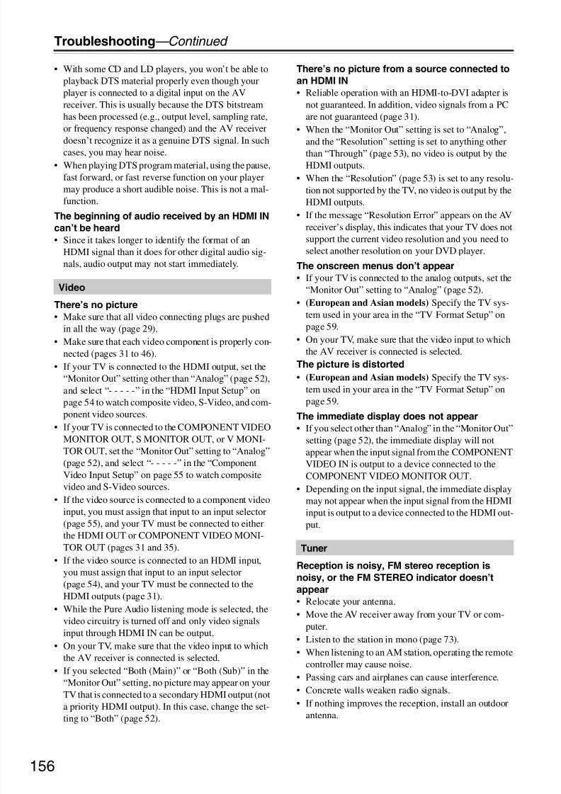
8/8/2019 Manual TX-NR5007 English
http://slidepdf.com/reader/full/manual-tx-nr5007-english 156/164156
Troubleshooting—Continued
• With some CD and LD players, you won’t be able toplayback DTS material properly even though yourplayer is connected to a digital input on the AVreceiver. This is usually because the DTS bitstreamhas been processed (e.g., output level, sampling rate,or frequency response changed) and the AV receiver
doesn’t recognize it as a genuine DTS signal. In suchcases, you may hear noise.
• When playing DTS program material, using the pause,fast forward, or fast reverse function on your playermay produce a short audible noise. This is not a mal-function.
The beginning of audio received by an HDMI IN
can’t be heard
• Since it takes longer to identify the format of anHDMI signal than it does for other digital audio sig-nals, audio output may not start immediately.
There’s no picture
• Make sure that all video connecting plugs are pushedin all the way (page 29).
• Make sure that each video component is properly con-nected (pages 31 to 46).
• If your TV is connected to the HDMI output, set the“Monitor Out” setting other than “Analog” (page 52),and select “- - - - -” in the “HDMI Input Setup” onpage 54 to watch composite video, S-Video, and com-
ponent video sources.• If your TV is connected to the COMPONENT VIDEOMONITOR OUT, S MONITOR OUT, or V MONI-TOR OUT, set the “Monitor Out” setting to “Analog”(page 52), and select “- - - - -” in the “ComponentVideo Input Setup” on page 55 to watch compositevideo and S-Video sources.
• If the video source is connected to a component videoinput, you must assign that input to an input selector(page 55), and your TV must be connected to eitherthe HDMI OUT or COMPONENT VIDEO MONI-TOR OUT (pages 31 and 35).
• If the video source is connected to an HDMI input,you must assign that input to an input selector(page 54), and your TV must be connected to theHDMI outputs (page 31).
• While the Pure Audio listening mode is selected, thevideo circuitry is turned off and only video signalsinput through HDMI IN can be output.
• On your TV, make sure that the video input to whichthe AV receiver is connected is selected.
• If you selected “Both (Main)” or “Both (Sub)” in the“Monitor Out” setting, no picture may appear on your
TV that is connected to a secondary HDMI output (nota priority HDMI output). In this case, change the set-ting to “Both” (page 52).
There’s no picture from a source connected to
an HDMI IN
• Reliable operation with an HDMI-to-DVI adapter isnot guaranteed. In addition, video signals from a PCare not guaranteed (page 31).
• When the “Monitor Out” setting is set to “Analog”,
and the “Resolution” setting is set to anything otherthan “Through” (page 53), no video is output by theHDMI outputs.
• When the “Resolution” (page 53) is set to any resolu-tion not supported by the TV, no video is output by theHDMI outputs.
• If the message “Resolution Error” appears on the AVreceiver’s display, this indicates that your TV does notsupport the current video resolution and you need toselect another resolution on your DVD player.
The onscreen menus don’t appear
• If your TV is connected to the analog outputs, set the“Monitor Out” setting to “Analog” (page 52).
• (European and Asian models) Specify the TV sys-tem used in your area in the “TV Format Setup” onpage 59.
• On your TV, make sure that the video input to whichthe AV receiver is connected is selected.
The picture is distorted
• (European and Asian models) Specify the TV sys-tem used in your area in the “TV Format Setup” onpage 59.
The immediate display does not appear• If you select other than “Analog” in the “Monitor Out”
setting (page 52), the immediate display will notappear when the input signal from the COMPONENTVIDEO IN is output to a device connected to theCOMPONENT VIDEO MONITOR OUT.
• Depending on the input signal, the immediate displaymay not appear when the input signal from the HDMIinput is output to a device connected to the HDMI out-put.
Reception is noisy, FM stereo reception is
noisy, or the FM STEREO indicator doesn’t
appear
• Relocate your antenna.• Move the AV receiver away from your TV or com-
puter.• Listen to the station in mono (page 73).• When listening to an AM station, operating the remote
controller may cause noise.• Passing cars and airplanes can cause interference.• Concrete walls weaken radio signals.• If nothing improves the reception, install an outdoor
antenna.
Video
Tuner

8/8/2019 Manual TX-NR5007 English
http://slidepdf.com/reader/full/manual-tx-nr5007-english 157/164157
Troubleshooting—Continued
The remote controller doesn’t work
• Make sure that the batteries are installed with the cor-rect polarity (page 14).
• Install new batteries. Don’t mix different types of bat-
teries, or old and new batteries (page 14).• Make sure that the remote controller is not too far
away from the AV receiver, and that there’s noobstruction between the remote controller and the AVreceiver’s remote control sensor (page 14).
• Make sure that the AV receiver is not subjected todirect sunshine or inverter-type fluorescent lights.Relocate if necessary.
• If the AV receiver is installed in a rack or cabinet withcolored-glass doors, the remote controller may notwork reliably when the doors are closed.
• Make sure you’ve selected the correct remote control-ler mode (pages 15 and 143 to 149).
• When using the remote controller to control othermanufacturers’ AV components, some buttons maynot work as expected.
• Make sure you’ve entered the correct remote controlcode (page 141).
• Make sure to set the same ID on both the AV receiverand remote controller (page 112).
Can’t control other components
• If it’s an Onkyo component, make sure that theu
cable and analog audio cable are connected properly.Connecting only anu cable won’t work (page 47).• Make sure you’ve selected the correct remote control-
ler mode (pages 15 and 143 to 149).• If you’ve connected anu-capable Onkyo MD
recorder, CD recorder, RI Dock to the TV/TAPE IN/ OUT jacks, or an RI Dock to the GAME IN or VCR/ DVR IN jacks, for the remote controller to work prop-erly, you must set the display to MD, CDR, or DOCK(page 60).If you cannot operate it, you will need to enter theappropriate remote control code (page 141).
• To control another manufacturer’s component, pointthe remote controller at that component.
• If none of the codes work, use the Learning functionto learn the commands of the other component’sremote controller (page 152).
• With some AV components, certain buttons may notwork as expected, and some may not work at all.
• To control an Onkyo component that’s connected viau, point the remote controller at the AV receiver. Besure to enter the appropriate remote control code first(page 142).
• To control an Onkyo component that’s not connectedviau, or another manufacturer’s component, pointthe remote controller at the component. Be sure toenter the appropriate remote control code first(page 141).
• The entered remote control code may not be correct. If more than one code is listed, try each one.
Can’t learn commands from another remote
controller
• When learning commands, make sure that the trans-
mitting ends of both remote controllers are pointing ateach other.• Are you trying to learn from a remote controller that
cannot be used for learning? Some commands cannotbe learned, especially those that contain severalinstructions.
There’s no sound
• Make sure your iPod is actually playing.• Make sure your iPod is inserted properly in the Dock.
• Make sure the UP-A1 Dock is connected to the UNI-VERSAL PORT jack on the AV receiver.• Make sure the AV receiver is turned on, the correct
input source is selected, and the volume is turned up.• Make sure the plugs are pushed in all the way.• Try resetting your iPod.
There’s no video
• Make sure that your iPod’s TV OUT setting is set toOn.
• Make sure the correct input is selected on your TV orthe AV receiver.
• Some versions of the iPod do not output video.The AV receiver’s remote controller doesn’t
control your iPod
• Make sure your iPod is properly inserted in the Dock.If your iPod is in a case, it may not connect properlyto the Dock. Always remove your iPod from the casebefore inserting it into the Dock.
• The iPod cannot be operated while it’s displaying theApple logo.
• Make sure you’ve selected the right remote mode.• When you use the AV receiver’s remote controller,
point it toward your amp.
• If you still can’t control your iPod, start playback bypressing your iPod’s Play button. Remote operationshould then be possible.
• Try resetting your iPod.• Depending on your iPod, some buttons may not work
as expected.• You can’t control your iPod if the battery is extremely
low. Use the iPod after recharging for a while.
The AV receiver unexpectedly selects your iPod
as the input source
• Always pause iPod playback before selecting a differ-ent input source. If playback is not paused, the Direct
Change function may select your iPod as the inputsource by mistake during the transition betweentracks.
Remote Controller
Dock for iPod

8/8/2019 Manual TX-NR5007 English
http://slidepdf.com/reader/full/manual-tx-nr5007-english 158/164158
Troubleshooting—Continued
Can’t record
• On your recorder, make sure the correct input isselected.
• To prevent signal loops and damage to the AV
receiver, input signals are not fed through to outputswith the same name (e.g., TAPE IN to TAPE OUT orVCR/DVR IN to VCR/DVR OUT).
• When the Pure Audio listening mode is selected,recording is not possible because no video signals areoutput. Select another listening mode.
There’s no sound
• Only components connected to analog inputs can beplayed in Zone 2/3.
Can’t access the server or Internet radio
• Check the network connection between the AVreceiver and your router or switch.
• Make sure that your modem and router are properlyconnected, and make sure they are both turned on.
• Make sure the server is up and running and compatiblewith the AV receiver (page 125).
• Check the “Network Settings”(page 126).
Playback stops while listening to music files on
the server
• Make sure your server is compatible with the AVreceiver (page 125).
• If you download or copy large files on your computer,playback may be interrupted. Try closing any unusedprograms, use a more powerful computer, or use adedicated server.
• If the server is serving large music files to several net-worked devices simultaneously, the network maybecome overloaded and playback may be interrupted.Reduce the number of playback devices on the net-
work, upgrade your network, or use a switch insteadof a hub.
Can’t connect to the AV receiver from a Web
browser
• If you’re using DHCP, your router may not alwaysallocate the same IP address to the AV receiver, so if you find that you can’t connect to a server or Internetradio station, recheck the AV receiver’s IP address onNetwork screen.
• Check the Network settings (page 126).
Can’t access the music files on a USB device
• Make sure the USB device is plugged in properly.• The AV receiver supports USB devices that support
the USB mass storage device class. However, play-
back may not be possible with some USB deviceseven if they conform to the USB mass storage deviceclass.
• USB memory devices with security functions cannotbe played.
The sound changes when I connect my
headphones
• When a pair of headphones is connected, the listeningmode is set to Stereo, unless it’s already set to Stereo,
Mono, Direct, Pure Audio or DTS Surround Sensa-tion.
The speaker distance cannot be set as required
• In some cases, corrected values suitable for home the-ater use may be set automatically.
The display doesn’t work
• The display is turned off when the Pure Audio listen-ing mode is selected.
How do I change the language of a multiplex
source
• Use the “Multiplex” setting on the “Audio Adjust”
menu to select “Main” or “Sub” (page 100).Theu functions don’t work
• To useu, you must make anu connection and ananalog audio connection (RCA) between the compo-nent and AV receiver, even if they are connected digi-tally (page 47).
• While Zone 2 or Zone 3 is selected, theu functionsdon’t work.
The functions Auto Power On/Standby and
Direct Change don’t work for components
connected viau
• These functions don’t work when Zone 2/3 is turnedon.
When performing “Audyssey MultEQ ® XT
Room Correction and Speaker Setup”, the
measurement fails showing the message
“Ambient noise is too high.”.
• This can be caused by any malfunction in your speakerunit. Check if the unit produces normal sounds.
Recording
Zone 2/3
Music Server and Internet Radio
USB Mass Storage Device Playback
Others

8/8/2019 Manual TX-NR5007 English
http://slidepdf.com/reader/full/manual-tx-nr5007-english 159/164159
Troubleshooting—Continued
The following settings can be made for the S-
Video, composite video and COMPONENT
VIDEO inputs
You must use the buttons on the AV receiver to makethese settings.1. While holding down the input selector button for the
input source that you want to set, press the [SETUP]button.
2. Use the Left and Right [e]/[r] buttons to changethe setting.
3. Press the input selector button for the input sourcethat you want to set when you’ve finished.
• Video Attenuation
This setting can be made for the DVD/BD, VCR/ DVR, CBL/SAT, GAME, AUX1, or COMPONENTVIDEO input. (You need to assign the input sourcefor COMPONENT VIDEO input.)
If you have a games console connected to theS-Video, composite and component video input, andthe picture isn’t very clear, you can attenuate thegain.
Video ATT:OFF: (default).Video ATT:ON: Gain is reduced by 2 dB.
The AV receiver can upconvert component video, S-Video, and composite video sources for display on a TVconnected to the HDMI outputs. However, if the picture
quality of the source is poor, upconversion may make thepicture worse or disappear altogether.In this case, try the following:
1 If the video source is connected to a component
video input, connect your TV to the
COMPONENT VIDEO MONITOR OUT.
If the video source is connected to an S-Video input,connect your TV to a MONITOR OUT S.If the video source is connected to a composite videoinput, connect your TV to the MONITOR OUT V.
2 On the main menu, select “1. Input/OutputAssign”, and then select “2. HDMI Input”.
Select the relevant input selector, and assign it to
“- - - - -” (page 54).
3 On the main menu, select “1. Input/Output
Assign”, and then select “3. Component Video
Input” (page 55):
If the video source is connected to COMPONENTVIDEO IN1, select the relevant input selector, andassign it to “IN1”.
If the video source is connected to COMPONENTVIDEO IN2, select the relevant input selector, andassign it to “IN2”.
If the video source is connected to COMPONENTVIDEO IN3, select the relevant input selector, andassign it to “IN3”.
If the video source is connected to an S-Video inputor composite video input, select the relevant inputselector, and assign it to “- - - - -”.
If “Monitor Out” setting is set to “Analog”, press [VCR/
DVR] and [RETURN] buttons on the AV receiver at thesame time. Select “Skip” in the “VideoProcessor” settingby pressing the [RETURN] button repeatedly on the dis-play. To reset back to the original setting, press the samebutton at the same time. If you select “Use”, the AVreceiver will output video signals from the video proces-sor.
The AV receiver contains a microcomputer for signal pro-
cessing and control functions. In very rare situations,
severe interference, noise from an external source, or
static electricity may cause it to lockup. In the unlikely
event that this happens, unplug the power cord from the
wall outlet, wait at least five seconds, and then plug itback in again.
Onkyo is not responsible for damages (such as CD
rental fees) due to unsuccessful recordings caused by
the unit’s malfunction. Before you record important
data, make sure that the material will be recorded cor-
rectly.
Before disconnecting the power cord from the wall out-
let, set the AV receiver to Standby.
Important Note Regarding Video Playback

8/8/2019 Manual TX-NR5007 English
http://slidepdf.com/reader/full/manual-tx-nr5007-english 160/164160
Specifications (TX-NR3007)
Amplifier Section
Video Section
Tuner Section
General
Video Inputs
Video Outputs
Audio Inputs
Audio Outputs
Control Terminal
Specifications and features are subject to change withoutnotice.
Rated Output PowerAll channels: North American:
140 watts minimum continuouspower per channel, 8 ohm loads, 2channels driven from 20 Hz to 20
kHz, with a maximum totalharmonic distortion of 0.05% (FTC)160 watts minimum continuous powerper channel, 8 ohm loads, 2 channelsdriven at 1 kHz, with a maximum totalharmonic distortion of 0.7% (FTC)170 watts minimum continuous powerper channel, 6 ohm loads, 2 channelsdriven at 1 kHz, with a maximum totalharmonic distortion of 0.1% (FTC)
Others:9 ch × 200 W at 6 ohms, 1 kHz, 1 chdriven (IEC)
Maximum Output PowerAsian:
9 ch × 250 W at 6 ohms, 1 kHz, 1 chdriven (JEITA)Dynamic Power 320 W (3 Ω, Front)
270 W (4 Ω, Front)160 W (8 Ω, Front)
THD (Total Harmonic Distortion)0.05%
Damping Factor 60 (Front, 1 kHz, 8 Ω)Input Sensitivity and Impedance
200 mV/47 kΩ (LINE)2.5 mV/47 kΩ, (PHONO MM)
Output Level and Impedance200 mV/470 Ω (REC OUT)
Phono Overload 70 mV (MM 1 kHz 0.5%)
Frequency Response 5 Hz - 100 kHz/+1 dB - 3 dB (LINE)Tone Control ±10 dB, 50 Hz (BASS)
±10 dB, 20 kHz (TREBLE)Signal to Noise Ratio 110 dB (LINE, IHF-A)
80 dB (PHONO, IHF-A)Speaker Impedance 4 Ω - 16 Ω
Input Sensitivity/Output Level and Impedance1 Vp-p/75Ω (Component and S-Video Y)
0.7 Vp-p/75Ω (Component PB /CB, PR /CR)
0.28 Vp-p/75 Ω (S-Video C)1 Vp-p/75 Ω (Composite)
Component Video Frequency Response5 Hz - 100 MHz - 3 dB
FM Tuning Frequency RangeNorth American:87.5 MHz - 107.9 MHzOthers: 87.5 MHz - 108.0 MHz, RDS
AM Tuning Frequency RangeNorth American:530 kHz - 1710 kHzOthers: 522 kHz - 1611 kHz
Preset Channel 40
Digital Tuner (North American models only):SIRIUS
Power Supply North American:AC 120 V, 60 HzOthers: AC 220 - 240 V, 50/60 Hz
Power Consumption North American: 11.6 AOthers: 1060 W
Dimensions (W × H × D)
435 × 198.5 × 463.5 mm
17-1/8" × 7-13/16" × 18-1/4"Weight 25.0 kg (55.1 lbs.)
HDMI IN1 (DVD/BD), IN2 (VCR/DVR),IN3 (CBL/SAT), IN4 (GAME),IN5 (AUX2), IN6, AUX1 (Front)
Component IN1 (DVD/BD), IN2 (CBL/SAT),IN3 (GAME)
S-Video DVD/BD, VCR/DVR, CBL/SAT,GAME
Composite DVD/BD, VCR/DVR, CBL/SAT,GAME, AUX1 (Front)
HDMI OUT MAIN, OUT SUBComponent MONITOR OUTS-Video MONITOR OUT,
VCR/DVR (REC OUT)Composite MONITOR OUT,
VCR/DVR (REC OUT), ZONE 2 OUT
Digital Inputs Optical: 2 (Rear), 1 (Front)Coaxial: 3 (Rear)
Analog Inputs MULTI CH, DVD/BD, VCR/DVR,CBL/SAT, GAME, AUX2, TV/TAPE,CD, PHONO, AUX1 (Front)
Multichannel Inputs 7.1
Analog Outputs VCR/DVR, TV/TAPE, ZONE2 PREOUT, ZONE3 PRE OUT
Multichannel Pre Outputs9
Subwoofer Pre Outputs 2Speaker Outputs FL, FR, C, SL, SR, SBL/Z3L, SBR/
Z3R, LH, RH, LW/Z2L, RW/Z2RPhones 1
MIC YesRS232 1Ethernet 1IR Input 1IR Output 112 V Trigger Out ZONE2 / ZONE3USB Yes (Front)
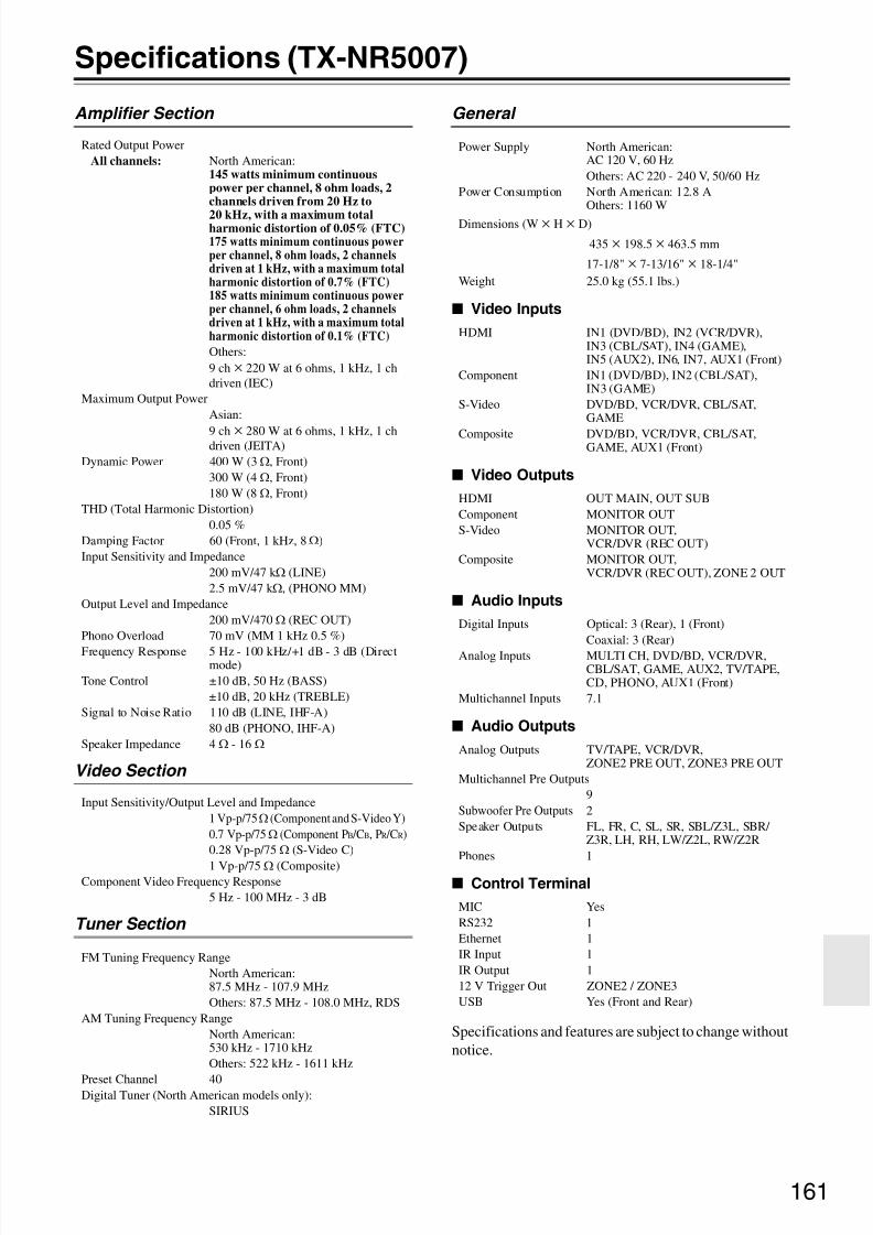
8/8/2019 Manual TX-NR5007 English
http://slidepdf.com/reader/full/manual-tx-nr5007-english 161/164161
Specifications (TX-NR5007)
Amplifier Section
Video Section
Tuner Section
General
Video Inputs
Video Outputs
Audio Inputs
Audio Outputs
Control Terminal
Specifications and features are subject to change withoutnotice.
Rated Output PowerAll channels: North American:
145 watts minimum continuouspower per channel, 8 ohm loads, 2channels driven from 20 Hz to
20 kHz, with a maximum totalharmonic distortion of 0.05% (FTC)175 watts minimum continuous powerper channel, 8 ohm loads, 2 channelsdriven at 1 kHz, with a maximum totalharmonic distortion of 0.7% (FTC)185 watts minimum continuous powerper channel, 6 ohm loads, 2 channelsdriven at 1 kHz, with a maximum totalharmonic distortion of 0.1% (FTC)
Others:9 ch × 220 W at 6 ohms, 1 kHz, 1 chdriven (IEC)
Maximum Output PowerAsian:
9 ch × 280 W at 6 ohms, 1 kHz, 1 chdriven (JEITA)Dynamic Power 400 W (3 Ω, Front)
300 W (4 Ω, Front)180 W (8 Ω, Front)
THD (Total Harmonic Distortion)0.05 %
Damping Factor 60 (Front, 1 kHz, 8 Ω)Input Sensitivity and Impedance
200 mV/47 kΩ (LINE)2.5 mV/47 kΩ, (PHONO MM)
Output Level and Impedance200 mV/470 Ω (REC OUT)
Phono Overload 70 mV (MM 1 kHz 0.5 %)
Frequency Response 5 Hz - 100 kHz/+1 dB - 3 dB (Directmode)
Tone Control ±10 dB, 50 Hz (BASS)±10 dB, 20 kHz (TREBLE)
Signal to Noise Ratio 110 dB (LINE, IHF-A)80 dB (PHONO, IHF-A)
Speaker Impedance 4 Ω - 16 Ω
Input Sensitivity/Output Level and Impedance1 Vp-p/75Ω (Component and S-Video Y)
0.7 Vp-p/75Ω (Component PB /CB, PR /CR)
0.28 Vp-p/75 Ω (S-Video C)
1 Vp-p/75 Ω (Composite)Component Video Frequency Response
5 Hz - 100 MHz - 3 dB
FM Tuning Frequency RangeNorth American:87.5 MHz - 107.9 MHzOthers: 87.5 MHz - 108.0 MHz, RDS
AM Tuning Frequency RangeNorth American:530 kHz - 1710 kHzOthers: 522 kHz - 1611 kHz
Preset Channel 40Digital Tuner (North American models only):SIRIUS
Power Supply North American:AC 120 V, 60 HzOthers: AC 220 - 240 V, 50/60 Hz
Power Consumption North American: 12.8 AOthers: 1160 W
Dimensions (W × H × D)
435 × 198.5 × 463.5 mm
17-1/8" × 7-13/16" × 18-1/4"Weight 25.0 kg (55.1 lbs.)
HDMI IN1 (DVD/BD), IN2 (VCR/DVR),IN3 (CBL/SAT), IN4 (GAME),IN5 (AUX2), IN6, IN7, AUX1 (Front)
Component IN1 (DVD/BD), IN2 (CBL/SAT),IN3 (GAME)
S-Video DVD/BD, VCR/DVR, CBL/SAT,GAME
Composite DVD/BD, VCR/DVR, CBL/SAT,GAME, AUX1 (Front)
HDMI OUT MAIN, OUT SUBComponent MONITOR OUTS-Video MONITOR OUT,
VCR/DVR (REC OUT)Composite MONITOR OUT,
VCR/DVR (REC OUT), ZONE 2 OUT
Digital Inputs Optical: 3 (Rear), 1 (Front)Coaxial: 3 (Rear)
Analog Inputs MULTI CH, DVD/BD, VCR/DVR,CBL/SAT, GAME, AUX2, TV/TAPE,CD, PHONO, AUX1 (Front)
Multichannel Inputs 7.1
Analog Outputs TV/TAPE, VCR/DVR,ZONE2 PRE OUT, ZONE3 PRE OUT
Multichannel Pre Outputs9
Subwoofer Pre Outputs 2Speaker Outputs FL, FR, C, SL, SR, SBL/Z3L, SBR/
Z3R, LH, RH, LW/Z2L, RW/Z2RPhones 1
MIC YesRS232 1Ethernet 1IR Input 1IR Output 112 V Trigger Out ZONE2 / ZONE3USB Yes (Front and Rear)

8/8/2019 Manual TX-NR5007 English
http://slidepdf.com/reader/full/manual-tx-nr5007-english 162/164162
Video Resolution Chart
The following tables show how video signals at different resolutions are output by the AV receiver.
*1: The output is limited to 480p for an effective signal in the effect of Macrovision.
*2: The output is limited to 576p for an effective signal in the effect of Macrovision.
: Output
NTSC
HDMI COMPONENT S-VIDEO COMPOSITE
1080p 1080i 720p 480p 480i 1080p 1080i 720p 480p 480i 480i 480i
HDMI
1080p
1080i
720p
480p
480i
COMPONENT
1080p
1080i
720p
480p *1
*1
480i *1
*1
S-VIDEO 480i *1 *1
COMPOSITE 480i *1
*1
Output
Input
PAL
HDMI COMPONENT S-VIDEO COMPOSITE
1080p 1080i 720p 576p 576i 1080p 1080i 720p 576p 576i 576i 576i
HDMI
1080p
1080i
720p
576p
576i
COMPONENT
1080p
1080i
720p
576p *2
*2
576i *2
*2
S-VIDEO 576i *2
*2
COMPOSITE 576i *2
*2
Output
Input

8/8/2019 Manual TX-NR5007 English
http://slidepdf.com/reader/full/manual-tx-nr5007-english 163/164163
Memo

8/8/2019 Manual TX-NR5007 English
http://slidepdf.com/reader/full/manual-tx-nr5007-english 164/164