manual of standard practice - the alberta land … · of surveying. has a particular ... after...
TRANSCRIPT

Alberta Land Surveyors’ Association
MANUAL OF STANDARD PRACTICE
April 25, 1996
(includes amendments to April 28, 2007)

Manual of Standard Practice -Table of Contents- 2005.04.23
TABLE OF CONTENTS PART A: Introduction
PART B: Standards of Practice
Section 1 Code of Ethics Section 2 Advertising Guidelines Section 3 Technical Services Sub-contracting
PART C: General Standards and Procedures
Section 1 Measurements and Accuracies Section 2 Measurements and Accuracies for GPS Surveys Section 3 Boundaries and Monumentation Section 4 Field Notes Section 5 Integrated Surveys
PART D: Standard Practice for Surveys and Plans
Section 1 General Requirements for Plans Section 2 Subdivision Surveys Section 3 Strata and Condominium Surveys Section 4 Right-of-Way Surveys Section 5 Wellsite and Public Land Dispositions Section 6 Descriptive Plans Section 7 Real Property Reports Section 8 Township Section 9 Construction Layout Surveys Section 10 Surveys in Unsurveyed Territory - Other Than Traverse Plans
PART E: Appendices
Section 1 Director of Surveys Road Allowance Policy Section 2 Natural Boundaries Section 3 Guidelines for Retracements and Restorations Section 4 Standard Affidavits Schedule “A”: Alberta Land Surveyor’s Real Property Report Certification Schedule “B”: Certification Section 5 Geometrical Deformation Survey Guidelines Section 6 Process and Obligation to Register Plans on Metis Settlements with Metis Settlements Land Registry Section 7 Index of Reference Information
DEFINITIONS
INDEX
NOTE: To reduce the complexity and confusion resulting from use of “he/she”, “he” will be used, without prejudice, throughout this manual when referring to Alberta Land Surveyors.
Manual of Standard Practice -Introduction- Part A 1997.04.27 Page 1
PART A
INTRODUCTION
The Alberta Land Surveyors’ Association is a self-governing profession established according to the Land Surveyors Act (RSA 2000, c.L-4.1)
This legislation provides for the establishment and maintenance of standards for surveys conducted by Alberta Land Surveyors in keeping with the requirements of other regulatory authorities.
The purpose of this Manual is to assist the Alberta Land Surveyor in practising, with integrity and competence, and to ensure surveys and survey plans result in clear and unambiguous definitions of boundaries.
All standards in this manual should be followed by the Alberta Land Surveyor. Where full compliance is not possible because of local conditions, conflicting requirements of other authorities or other circumstances, the onus is on the Alberta Land Surveyor to be able to defend noncompliance.
There is also an onus on the Alberta Land Surveyor to improve the manual and to participate in keeping it current. If a surveyor believes the existence or absence of a standard is necessary, he has an obligation to bring recommendations for change to the membership.
Manual of Standard Practice -Code of Ethics - Part B 2004.04.24 Page 1
PART B, STANDARDS OF PRACTICE Section 1:
CODE OF ETHICS (With Commentary)
Numbers changed to match Alberta Regulation 324/82 2004.04.24
The Code of Ethics represents a standard of conduct for the Alberta Land Surveyor. It stresses the Alberta Land Surveyor’s responsibility to the public and clients and to his personnel and colleagues.
Those who rely on an Alberta Land Surveyor may find it difficult to assess the quality of his services. They have a right, however, to expect a person of integrity and competence.
Because ethics are abstract concepts they are not easily defined. Therefore, care must be used in applying the Code of Ethics to judge the Alberta Land Surveyor. There could be cases when certain parts of the commentary should not be strictly enforced. Similarly, the code cannot cover all instances of unethical conduct. It is the responsibility of the Association to judge whether the Code is followed not so much in fact, as in spirit.
The Code 1 An Alberta Land Surveyor shall serve society, his clientele and his profession with the ultimate objective of contributing to the knowledge of land, to the better management of land and to the preservation of peaceful and lawful enjoyment of land.
The public responsibility of an Alberta Land Surveyor to contribute in the above areas imposes particular obligations. Especially important is the work of establishing or re-establishing boundaries of land. The correct survey or resurvey of land boundaries is essential to the maintenance of the land survey and titles system in the province of Alberta. An Alberta Land Surveyor shall at all times maintain the cadastral fabric.
This public interest must be greater than the interest of any individual client of the Alberta Land Surveyor and requires that the professional carry out his duties without favour, affection or partiality.
Duty to Personnel 2(1) An Alberta Land Surveyor has a duty to assist his pupils and employees to achieve their optimum level of contribution to society through their contribution to the profession.
An Alberta Land Surveyor
shall assist his students/trainees and employees to obtain instruction in the practical, ethical and theoretical aspects of surveying.
has a particular obligation to ensure students/trainees receive instruction in the art, practice, ethics and profession of an Alberta Land Surveyor.

Manual of Standard Practice -Code of Ethics - Part B 2004.04.24 Page 2
Professional Impropriety (2) An Alberta Land Surveyor should avoid even the appearance of professional impropriety.
An Alberta Land Surveyor
shall disclose to his client any conflict of interest, affiliation or prior involvement that could have even the appearance of preventing the surveyor from carrying out professional duties with independence and objectivity. The surveyor should accept or continue such employment only if the client consents.
in doing work for clients who could have conflicting interests, must explain fully to each the implications of common representation. He should accept or continue such employment only if all clients consent and the duties can be carried out with independence and objectivity. A conflicting interest could occur where the timing or completion of projects or approval of plans gives one client an advantage over another.
must recommend that his client retain another Alberta Land Surveyor if any conflict of interest, affiliation, or prior involvement prevents him from carrying out professional duties with independence and objectivity.
shall not solicit employment by offering payment or other inducement to secure such employment. This includes compensation to a third party for recommending him.
must attempt to resolve amicably any controversy over fees with clients. The surveyor shall explain all charges incurred and make available to the client copies of any details relevant to the assessment. Where differences cannot be resolved, the surveyor shall ensure that the client has knowledge of complaint or mediation procedures available through the Alberta Land Surveyors’ Association.
shall not influence improperly any public body or official; or state or imply that he is able to do so.
shall guard the reputation of his profession as he guards his own, rebutting unjustified criticism of the profession, other surveyors or of him/herself.
shall not allow his name to be associated in a professional manner with any person or enterprise of a dubious nature.
Professional Confidences (3) An Alberta Land Surveyor has a duty to preserve the confidences of his client and regard as privileged the information he may obtain regarding the affairs of his client.
An Alberta land surveyor
shall maintain confidentiality of clients’ affairs during and after completion of an assignment or termination of employment.

Manual of Standard Practice -Code of Ethics - Part B 2004.04.24 Page 3
is responsible for compliance of students/trainees and staff with this article, therefore, must exercise care in selection and training of employees.
This article does not apply to the normal release on request of boundary definition survey information to other Alberta Land Surveyors.
Professional Judgement (4) An Alberta Land Surveyor has a duty to exercise unbiased independent professional judgement on behalf of his client, and shall represent his client competently.
An Alberta Land Surveyor
must decline to accept direction from employers, directors, officers, or other superiors in his organization if such direction compromises his integrity, independence or objectivity. A written agreement between organization and surveyor should be in place to prevent any misunderstandings. The agreement should define the relationship and allow the surveyor independence of action and decisions.
when forming a corporation, must ensure that any director, officer or stockholder cannot influence the independence of any Alberta Land Surveyor employed by the corporation in carrying out his professional duties.
shall not accept assignments that are beyond his resources to complete in a reasonable time, that are beyond his competence or that he cannot carry out in a professional manner. This does not necessarily preclude the surveyor from accepting employment in an area in which he may not be completely proficient, providing the client is made fully aware of his capability, in good faith he expects to become qualified and his accepting the assignment would not result in an undue delay or expense to his client.
if offered employment for which he is not and does not expect to become qualified, an Alberta Land Surveyor should either decline the employment or, with the consent of the client, accept the employment in association with another Alberta Land Surveyor with the required expertise.
shall present clearly to a client, circumstances where his professional judgement may be overruled by regulatory or legal authority and the consequences.
Integrity and Competence (5) An Alberta Land Surveyor shall assist in maintaining and improving the integrity and competence of the profession of surveying.
This responsibility includes maintaining the survey system, by cooperating with colleagues to resolve any apparent errors or discrepancies in his work and taking all necessary measures to remedy those errors or discrepancies.
An Alberta Land Surveyor shall

Manual of Standard Practice -Code of Ethics - Part B 2004.04.24 Page 4
report to the Association any matter of incompetence or disregard for good practice. To let inappropriate practice continue could result in a deterioration of the survey system and harm the integrity of the profession. Occasional errors or oversights in work, however, can often be resolved between surveyors and need not be reported to the Association unless the parties cannot agree to a solution to the matter.
assume the professional responsibility for all authorized work carried out by his nonprofessional staff.
ensure, before he accepts any applicant for articleship, that the applicant has the necessary personal attributes including good character required of an Alberta Land Surveyor.
devote some of his time to the affairs of his Association. Changes in human affairs and imperfections in human institutions make necessary constant efforts to maintain and improve the survey profession, institutions, procedures and system.
participate in proposing and supporting legislation and programs to improve the survey profession, institutions, procedures and system. If an Alberta Land Surveyor believes that the existence or absence of a rule of law, regulation or instruction causes or contributes to an unjust result, he should endeavor to obtain appropriate changes.
continually advance his knowledge and skills by participating in the activities of the Association, in relevant professional development programs and related professions or societies.
Dignity of the Profession (6) An Alberta Land Surveyor has a duty to maintain the dignity of the profession through his association with his clients, colleagues and subordinates.
An Alberta Land Surveyor shall
limit his advertising to the adequate provision of information to the public. Special care must be taken to ensure the information set forth in any advertising is relevant to the appropriate selection of a surveyor. Preparation of advertisements and professional articles for lay publications and participation in seminars, lectures and civic affairs should be motivated by a desire to educate the public and provide information relevant to the selection of the most appropriate Alberta Land Surveyor rather than to obtain publicity for particular surveyors.
refrain from any false or misleading statements or self-laudatory language in any advertising.

Manual of Standard Practice -Code of Ethics - Part B 2004.04.24 Page 5
not, in any dealing he has with a client or prospective client, attempt to solicit assignments or projects that are being carried out by another surveyor. If asked to participate in or complete a project being carried out by another surveyor, he shall do so only with the approval, withdrawal or termination of services of the previous surveyor.
not attempt to injure the professional reputation of any other Alberta Land Surveyor.
refrain from public criticism of the conduct or practice of any other Alberta Land Surveyor.
Professional Services (7) An Alberta Land Surveyor should assess and receive fair and just compensation from his client, commensurate with the technical complexity, level of responsibility and liability potential of the services performed.
An Alberta Land Surveyor shall
assess a fee that will enable him to serve the client effectively and complete the project using good survey practices. He shall not charge more than a reasonable fee that could discourage potential clients from using professional land surveyors for the protection of their property rights and that could generally harm the reputation of Alberta Land Surveyors.
when in the process of being employed, arrive at a clear agreement with the client for fees to be charged. This will prevent misunderstandings later and contribute to good relations.
in any estimates or quotations given to a prospective client, clearly outline the work covered by the estimate and any conditions which could contribute to additional costs. He should not quote a fixed fee for an unknown quantity of work unless the fee includes all contingencies. Once he has entered into an agreement to carry out survey work for a specified fee, he shall complete the work for the agreed amount.
not reduce the quality of his professional services to complete a project within the agreed cost.
not divide a fee for surveying services with another surveyor not a partner or associate of his survey firm unless:
— the client agrees to employment of an additional surveyor after full disclosure of a fee division is made,
— the division is proportional to the services performed, and
— the total fee does not exceed reasonable compensation for all services provided to the client.

Manual of Standard Practice -Code of Ethics - Part B 2004.04.24 Page 6
not use the advantage of a salaried position to compete unfairly with another Alberta Land Surveyor and will not engage in outside work without the knowledge and consent of his employer.
Unauthorized Practice (8) An Alberta Land Surveyor shall assist in preventing the unauthorized practice of land surveying.
An Alberta Land Surveyor shall
report to the Association any instances of unqualified persons practising land surveying. Limiting the practice of land surveying to professionals is intended to ensure the public receives these services with competence and integrity.
not enter into any arrangement that will enable an unqualified person or corporate body to complete a land survey directly or indirectly.
not join or become a member of a company which carries out survey work unless he or another Alberta Land Surveyor will be taking responsibility for all land survey work performed.
not establish offices or branches unless these centres are under the full-time direction and management of a resident Alberta Land Surveyor. In management of this nature, there is a real danger that nonprofessional personnel will assume, or appear to assume, professional duties and that supervision will be inadequate. It is essential that the client-surveyor relationship be retained in the practice of land surveying.
This article does not preclude an Alberta Land Surveyor from delegating tasks to field assistants, clerks, secretaries and others while the Alberta Land Surveyor maintains a direct relationship with his client and supervises the work.

Manual of Standard Practice -Advertising Guidelines - Part B 1996.04.27 Page 1
PART B, STANDARDS OF PRACTICE Section 2:
ADVERTISING GUIDELINES Advertisement 2.1 Advertisements shall:
• be in good taste.
• not be misleading by containing a misrepresentation of fact or creating unrealistic expectations.
• make no reference to price or fees for professional services.
• not be self-laudatory.
• be factual, without false or inaccurate information.
• be in the best interest of the public.
• not harm the dignity, integrity and honour of the profession.
Vehicle Signage 2.2 Alberta Land Surveyors shall place identification signage on all field vehicles used in the practice of surveying, with the company name to be a minimum of 5 cm in height. A logo, address and telephone number or any combination thereof may also be added. Signage of any subcontractors shall not be visible.
Manual of Standard Practice Part B 1996.04.27
-Technical Services Sub-Contracting - Page 1
PART B, STANDARDS OF PRACTICE Section 3:
TECHNICAL SERVICES SUB-CONTRACTING
3.1 An Alberta Land Surveyor:
.1 may engage the services of a person or persons, not in his direct employ, (referred to here as the subcontractor), to perform technical functions on his behalf. These technical functions do not include or encompass client liaison or new business development.
.2 shall assume full responsibility for the actions and conduct of the subcontractor during the term of the engagement as though he were in the land surveyor’s direct employ. The land surveyor will issue all work instructions to, and receive the completed work from, the subcontractor in person.
.3 shall not remunerate any of his technical assistants or the subcontractor for services based on a proportion of the entire fee which he charges a client for the whole service, nor a fixed fee which may encourage inferior methods or time-reducing procedures at cross purposes with adopted survey standards.

Manual of Standard Practice -Measurements and Accuracies - Part C 1999.04.23 Page 1
PART C, GENERAL STANDARDS AND PROCEDURES Section 1:
MEASUREMENTS AND ACCURACIES Method of Least Squares
Revised 1999.04.23
1.1 The following section deals with measurements and accuracies associated with cadastral boundary definition surveys. As measurement techniques evolve and new methodologies become available, the burden of proof that these guidelines or their intent are complied with rest with the practitioner assuming responsibility for the plan.
The measure of accuracy for cadastral surveys shall be determined by either employing the method of misclosure or the method of least squares.
Where the method of least squares is employed, the measure of accuracy shall include both the observational residuals and the semi-major axis of the 95% relative 2-dimensional (horizontal) and/or 1-dimensional (vertical) confidence regions between monuments in the survey.
The 95% confidence regions used to assess the accuracy shall be derived from a properly weighted minimally constrained adjustment of the network. The global variance factor computed by the adjustment must be tested with the Chi-Square Goodness of Fit Test. In the event that the variance factor does not pass this test, the reasons therefore should be determined and the problem rectified. Subsequently, if the test is still not passed, the variance-covariance matrix must be scaled by the global variance factor.
The minimum accuracy standard, when expressed as a confidence region, shall be obtained from the following formula:
c = 0.02 + ((b)(d)) metres where,
“c” is the maximum allowable value of the semi-major axis of the 95% relative confidence region,
“b” is the precision in parts per million (ppm)
“d” is the distance between monuments in metres
New Surveys 1.2 For new surveys consisting of the surveyor’s own work, the minimum accuracy standard,
• when expressed as a misclosure shall be 1:7500 or 0.02 metres or,
• when the method of least squares is employed, both the observational residuals and the semi-major axis from the 2-dimensional relative confidence regions, shall be as determined in section 1.1 using a value of (b) equal to 130 ppm.
Prior Surveys 1.3 When closing on work performed by other surveyors, the minimum accuracy standard,
• when expressed as a misclosure shall be 1:5000 or 0.02 meters or,

Manual of Standard Practice -Measurements and Accuracies - Part C 1999.04.23 Page 2
• when the method of least squares is employed, both the observational residuals and the semi-major axis from the 2-dimensional relative confidence regions, shall be as determined in section 1.1 using a value of (b) equal to 200 ppm.
Checking Work 1.4 All surveys conducted under the Surveys Act must be verified by one or more of the following:
• Closure on prior or current work,
• Closure on existing Alberta Survey Control,
• Check-measuring all observations, or
• Other appropriate means.
Sufficient field measurements shall be made to ensure there are no errors of layout or measurement.
Wellsite Surveys 1.5 The vertical accuracy within the surveyor’s own level circuits,
• when expressed as a misclosure, shall not exceed (+/- 50 mm) *( √d) where d is the distance in km or,
• when the method of least squares is employed, both the observational residuals and the 1-dimensional relative confidence regions, shall be as determined in section 1.1 using a value of (b) equal to 20 ppm.
• a minimum of two benchmarks with published elevations should be used and the result related to the appropriate vertical datum as specified in Part D, Section 1.2.
The horizontal accuracy of the surveyor’s own work,
• when expressed as a misclosure shall be 1:5000 or 0.02 meters or,
• when the method of least squares is employed, both the observation residuals and the semi-major axis from the 2-dimensional relative confidence regions, shall be as determined in section 1.1 using a value of (b) equal to 200 ppm.
When closing on work performed by other surveyors, the minimum accuracy standard,
• when expressed as a misclosure shall be 1:2500 or 0.02 meters or,
• when the method of least squares is employed, both the observational residuals and the semi-major axis from the 2-dimensional relative confidence region, shall be as determined in section 1.1 using a value of (b) equal to 400 ppm.

Manual of Standard Practice Part C 1999.04.23
-Measurements and Accuracies for GPS Surveys - Page 1
PART C, GENERAL STANDARDS AND PROCEDURES Section 2:
MEASUREMENTS AND ACCURACIES FOR GPS SURVEYS
Revised 1999.04.23 The following section deals with standards for GPS measurements and associated computations performed for cadastral boundary definition surveys. Due to the complexity of GPS measurement and data reduction processes, these guidelines focus primarily on assessing the reliability and accuracy of these surveys. As GPS techniques evolve and new methodologies become available, the burden of proof that these guidelines or their intent are complied with rest with the practitioner assuming responsibility for the plan.
2.1 GPS surveys will be assessed as horizontal (2D) and/or vertical (1D) surveys for the purposes of accuracy measure.
2.2 The measure of accuracy for surveys conducted in whole or in part with GPS techniques, shall comply with Section 1.
2.3 Network adjustment shall include only (n-1) position differences or, if trivial position differences are included, the mathematical correlations should be properly accounted for.
2.4 The position of every monument included in a GPS survey either found or placed shall be verified with sufficient redundant observations. This applies to both static and kinematic surveys.

Manual of Standard Practice -Boundaries and Monumentation - Part C 2001.04.21 Page 1
PART C, GENERAL STANDARDS AND PROCEDURES Section 3:
BOUNDARIES AND MONUMENTATION
Recommended Monuments 3.1 .1 Under the June 9, 1988 Surveys Act, statutory iron posts are required at all property corners.
.2 For surveys under Part 3 of the Surveys Act, an iron post approximately 90 centimetres long, 2 centimetres in diameter, pointed at one end with a 2 centimetre square top, 10 centimetres long and marked with a crown.
.3 Where it is not practical to place a statutory iron post, one of the following should be used:
• lead plug ‘with tack’ in drill hole for rock or concrete conditions.
• concrete nail ‘with washer’ for asphalt conditions.
• round, 2 centimetre diameter, solid steel bar for gravel conditions of a length to suit the circumstances.
.4 Other monuments may be used, at the surveyor’s discretion, if one of the above is impractical.
.5 Reference monuments may be used at an offset location if the actual corner is not accessible or if it is impractical to monument, but the reference monument must not create confusion or ambiguity.
Monuments 3.2 Monuments shall be, for surveys under Part 2 of the Surveys Act, a brass tablet 8 centimetres in diameter, marked with a crown and the words “Province of Alberta” and mounted on a base approved by the Director of Surveys, and where it is impractical to place a monument of a style specified above, the Director of Surveys may approve the use of a suitable substitute.
Marker Posts and Bearing Trees
3.3 Where practical, iron posts shall be referenced by a marker post placed 0.3 metres distant therefrom and the direction noted on the plan.
.1 Marker posts should not be placed where they may constitute a hazard to the public or interfere in the normal use of land. In general, marker posts should not be placed in developed urban areas.
.2 Marker posts placed along road or right-of-way surveys should be situated on adjacent fence lines whenever possible.
.3 For surveys in unsurveyed territory, bearing trees and/or marker posts are required.
.4 Where a marker post is placed other than 0.3 metres distant from a monument, both the distance and the direction of the marker post from the monument shall be noted on the plan.
.5 Marker posts must be of a design approved by the Alberta Land Surveyors’ Association.
Intersections 3.4 .1 When surveying boundaries that intersect surveyed section or quarter sections lines, the intersections shall be made using the

Manual of Standard Practice -Boundaries and Monumentation - Part C 2001.04.21 Page 2
Revised 2001.04.21 nearest section or quarter corners on each side of the point of intersection. If the monuments at these corners are lost, these lost corners and all section and quarter section corners between the survey evidence utilized to re-establish the lost corners, shall be re-established and monumented, giving due consideration to all available evidence.
Frequencies .2 With some exceptions, Part 3 of the Surveys Act requires that, in addition to intersections with existing survey lines, all new boundaries be monumented at every deflection and point of curvature. For further details, refer to the sections dealing with specific types of surveys.
Countersinking 3.5 Monuments shall be countersunk in areas where they interfere with farming or grading operations and noted on the plan.
It is good practice to reference and raise to ground level monuments found buried in urban residential areas when practical.
Boundary Types 3.6 All surveyed boundaries, other than natural boundaries, must be either straight lines or circular curve segments.
Permit Number 3.7 Statutory iron posts placed shall be legibly and permanently marked with the survey corporation or partnership permit number or the registration number of individual surveyors not affiliated with a surveyors partnership or surveyors corporation. The markings placed on the iron post shall be noted in the legend on the plan.
Establishment of Monuments Plan
3.8 If a statutory monument has been established but is not shown on a plan registered in the Land Titles Office, the surveyor must register a plan, called an Establishment of Monuments plan, within two years of the monument establishment. This does not negate Sections 44 and 46 of the Act.
Wellsites and Related Facilities
Revised 2004.24.04 3.9 The type of monumentation found or placed for wellsites and
related facilities shall be shown on the plan. It is recommended that 30 centimetre iron spikes or 30 centimetre iron bars be placed.
Iron Post Markings 3.10 If a statutory iron post is placed to re-establish a lost monument or restore an obliterated monument originally placed at a section or quarter section corner, the iron post shall be marked with the same designation as the original monument. Numbers shall be legibly and permanently applied.
Corner
Section Corner
Quarter Section
Centre of Section
Markings
Section, Township, Range
One Quarter (1/4)
One Quarter (1/4)
Marker Condition Report
Revised 1999.04.01
3.11 A survey control marker condition report on a form provided by the Director of Surveys shall be prepared and certified by a surveyor and submitted to the Director of Surveys for every survey control marker found disturbed, destroyed, not found, or incorrectly described on any survey.

Manual of Standard Practice -Field Notes- Part C 1996.09.03 Page 1
PART C, GENERAL STANDARDS AND PROCEDURES Section 4
FIELD NOTES The following requirements pertain to compiling, recording and
retaining of hardcopy field notes and digital returns that are made in conjunction with all surveys.
Systematic Records 4.1 .1 Systematic records shall be made of all field measurements at the time of observation and be identified as field notes.
.2 They shall be preserved permanently, in original form and filed such that ready retrieval is possible.
Contents of Notes 4.2 The field notes shall give a clear and detailed account of everything found, observed and done in the course of the survey including:
.1 the date of observations, location, and purpose of the survey;
.2 the type and identification of equipment;
.3 environmental conditions, including meteorological readings;
.4 the name of the person(s) making and recording the observations;
.5 a complete description of the condition of every monument found, restored and placed and of every permanent structure referencing that monument;
.6 a record of all physical, documentary or verbal searches made for evidence. All lost monuments shall be identified.
.7 a diagram representing the survey.
Changes/Edits 4.3 Entries in field notes, either hardcopy or digital shall not be erased, altered or obliterated.
Remote Positioning Data 4.4 In addition, for surveys done partially or completely using remote positioning techniques, the field records shall include the following:
.1 observation procedures, raw data and logistics;
.2 reduction procedures of the observed data, including software versions;
.3 processed remote positioning data from which cadastral survey measurements are derived.

Manual of Standard Practice -Integrated Surveys- Part C 2003.04.26 Page 1
PART C, GENERAL STANDARDS AND PROCEDURES Section 5
INTEGRATED SURVEYS Integrated Surveys 5.1 Every survey a plan of which is to be registered under the Land
Titles Act shall be integrated with survey control if 2 or more monuments found or placed by the survey are each within 1 kilometre of any 2 survey control markers.
5.2 For the purposes of Section 5.1, integration with survey control means obtaining sufficient measurements from survey control markers into the survey to permit the derivation of grid bearings and the computation of a closure starting at a survey control marker and proceeding along the shortest path through the survey to another survey control marker.
5.3 When computing a closure under Section 5.2, the error of closure when compared to the coordinates of the survey control markers, as confirmed and published by the Director of Surveys, shall not exceed the greater of:
.1 the product of 0.00014 and the direct distance between the 2 survey control markers used for the closure, or
.2 25 millimetres.
5.4 If a surveyor performs a survey within the bounds of a survey that has been integrated in accordance with Sections 5.1 to 5.3, then the requirements of Section 5.1 are optional.
Additional Requirements
Revised 2003.04.26
5.5 A plan of a survey performed pursuant to Section 5.2 shall show, in addition to the requirements of any enactment, all survey control markers to which the survey is connected, together with interconnections determined by the surveyor during the course of the survey. The plan must include the unique identifier number and tablet markings for the ASCMs.
Field Measurements 5.6 On every survey other than surveys meeting the requirements of Section 5.1, the surveyor shall make field measurements connecting the survey to all survey control markers situated within 1 kilometre of any monument found or placed by the survey.
Non-monumented Survey
Revised 2002.05.04
5.7 .1 A survey shall not be carried out under section 47 of the Surveys Act unless the survey is related to a minimum of two survey control markers.
.2 The density of survey control markers or reference monuments shall be such that no property corner established by the survey is more than 200 metres from the nearest reference monument or survey control marker.
.3 When computing the accuracy of the control ties to property and reference monuments, the accuracies shall be determined by:
.1 For survey control less than 2 kilometres to all property and reference monuments, the accuracy shall not exceed the greater of the product of 0.00014 and the direct distance between the 2 survey control markers for the closure, or 25 millimetres.

Manual of Standard Practice -Integrated Surveys- Part C 2003.04.26 Page 2
.2 For survey control greater than 2 kilometres to all property corners and reference monuments, the method of least squares shall be employed (see Part C Section 1.1) with the minimum standard value shown in the chart below.
Distance(m)
>2000
>5000
>10000
>20000
ppm
12.5
5.0
2.5
1.5
Plan of Non-Monumented Survey
5.8 Plans for surveys performed under Section 47 of the Surveys Act shall show, in addition to the requirements of any enactment.
.1 All survey control markers, reference monuments, found monuments and re-established monuments involved in the survey, together with their coordinate positions.
.2 The location of all monuments that would have been placed if the survey had been carried out under Section 45(1) of the Surveys Act together with their coordinate positions.

Manual of Standard Practice -General Requirements for Plans- Part D 2005.04.23 Page 1
PART D, STANDARD PRACTICE FOR SURVEYS AND PLANS Section 1
GENERAL REQUIREMENTS FOR PLANS Revised 2002.05.04 The Surveys Act defines the field requirements. The Land Titles
Office and certain acts provide the authority for the registration of plans of survey, and to some extent, specify the information that must be shown on plans. The following requirements supplement and enlarge upon the statutory provisions, to enable effective plan preparation.
In addition to the specifications and guidelines below, the Land Titles Procedures Manual should also be consulted for direction on subjects not covered in this manual.
The Land Titles Procedures Manual and the Policy and Procedures Manual for the submission of digital plans of survey for registration are both available on the internet at http://www3.gov.ab.ca/gs/.
Revised 2003.04.26 1.1 A notation shall be placed on the plan of survey describing the method used in re-establishing lost corners if this is not clear. (Refer to Part E, “Guidelines For Retracements and Restorations”, Sections 3.8 and 3.9.)
Datum/Origin for Bearings and Coordinates
Revised 2003.04.26
1.2 The recognized datum for spatially-referenced data in Alberta is the North American Datum, 1983 (NAD’83), using the GRS 80/WGS 84 ellipsoid. This datum and related ellipsoid therefore shall be used on all plans of survey registered in the Land Titles Office, if plan information relates to grid bearings or grid coordinates. The choice of map projections must be consistent with the requirements of the provincial mapping system.
The recommended vertical datum for spatially referenced data in Alberta is CVD28.
The plan of survey shall clearly show the datum or origin used for bearings and coordinates on the plan of survey as outlined below:
.1 Unless circumstances require greater accuracy, bearings should be shown to the nearest 5 seconds of arc. Ties to Survey Control Markers shall reflect the actual angle determined.
.2 All plans of survey pursuant to Section 47 of the Surveys Act; and Part C Section 5 of the Manual of Standard Practice, using grid bearings or grid coordinates, shall base grid bearings or grid coordinates on NAD’83 and show, in addition, to other requirements for plans, the following:
A note in the legend of the plan and header for grid coordinate listings indicating:
• the datum used,
• the projection used,
• the reference meridian,
• the combined factor (scale/elevation).

Manual of Standard Practice -General Requirements for Plans- Part D 2005.04.23 Page 2
.3 A surveyor who prepares a plan of survey in unsurveyed territory shall ensure that it meets the following requirements:
.1 Bearings are referred to either the astronomical meridian passing through the centre of the range in which the survey lies or the reference meridian appropriate to survey control, and an explanatory note stating the origin of the bearings is placed in the legend.
.2 Connections to survey control or existing surveys are verified and positions for all monuments can be determined relative to the position in the Alberta Township System of the north-east corner of section 33 on the base line in which the survey lies.
.3 The bearing of lines derived from astronomical observations is shown as such on the plan.
.4 On plans of Establishment of Monuments for Wellsite Control Traverse Purposes, a table on the plan showing coordinates for points in the survey relative to the north-east corner of Section 33 on the closest base line in the range in which the survey lies, oriented to the astronomical meridian through that point.
Ties 1.3 Linear and angular tie measurements must be shown in all directions from intersections with previously surveyed boundaries.
Curve Data
Revised 2005.04.23
1.4 Where any boundary or limit of a block, parcel or right-of-way has been surveyed as an arc of a circular curve, the length of the curve, its radius, and the central angle of curve shall be shown on the plan. Chord lengths and bearings with length of subtangents may also be shown but are not essential. When a circular curve boundary is non-tangential to an adjoining line segment boundary, radial bearings or a chord bearing and distance must also be shown.
NOTE: On subdivision plans having curvilinear boundaries, it may be desirable to show the delta angle to the nearest second of arc and the other curve-related information to millimetre precision. For multiple curves or curve segments, information may be shown in tabular form.
Closures 1.5 Each and every figure on a plan shall be checked for mathematical closure.

Manual of Standard Practice -Subdivision Surveys- Part D 2007.04.28 Page 1
PART D, STANDARD PRACTICE FOR SURVEYS AND PLANS Section 2
SUBDIVISION SURVEYS This section provides standards to be followed in the survey and
preparation of plans of subdivision. These standards are in addition to the statutory requirements of the Municipal Government Act, the Land Titles Act, the Surveys Act, and any regulations thereunder.
Delayed Posting 2.1 The use of delayed posting provisions under the Surveys Act is optional. This option is recommended where the subdivision plan must be registered prior to completion of construction operations.
2.2 The following standards apply to “delayed posting” subdivisions in addition to other applicable standards:
.1 The survey and reference control network shall be integrated with the surrounding and adjacent ASC markers. Stable reference monuments shall be strategically placed to ensure their maintenance until completion of posting. The reference network shall be designed to provide for redundancy in observations and to avoid hanging lines or hanging networks.
.2 All perimeter monumentation should be placed prior to registration of the plan of subdivision. At the surveyor’s discretion, perimeter monuments may be delayed when there is a possibility they will be destroyed during construction. When a perimeter boundary is common to a previously registered but unposted boundary, the coordinate positions of the previous plan govern until the Form 11.1 Land Titles Act Forms & Regulations, Monumentation Certificate, is registered at the Land Titles Office. The respective land surveyors should coordinate their plans and surveys to ensure no conflicts arise along the common boundary.
Added 2007.04.28 .3 In accordance with Section 47(3) of the Surveys Act, the surveyor shall, within one year of the registration of the plan, either place the monuments required by section 45(1) or submit a request for an extension, sufficient to complete the placing of the monuments, to the Director of Surveys stating the reason for the request. In all cases the surveyor shall, within the above time limits, register a Monument Certificate once the placing of the monuments is complete. The certificate shall contain a detailed description of the type and condition of all monuments placed and reasons for non-posting if any monuments were not placed.
Renumbered 2007.04.28 .4 Every effort shall be made to prepare Section 47 plans on one sheet. However, where two sheets are necessary:
• the second sheet shall contain only that information relevant for the period that the statutory monuments are not in place. This information includes the reference control network and a key plan of point numbers. It also may include the table of coordinates.

Manual of Standard Practice -Subdivision Surveys- Part D 2007.04.28 Page 2
• the second sheet shall be numbered “SHEET 2 of 2”. Sheet one must contain a statement indicating what information is contained on sheet 2.
Revised 2005.04.23; Renumbered 2007.04.28
.5 Grid (NAD83) co-ordinates must be shown on the plan or on a separate document registered along with the plan.

Manual of Standard Practice -Strata and Condominium Surveys- Part D 2002.05.04 Page 1
PART D, STANDARD PRACTICE FOR SURVEYS AND PLANS Section 3
STRATA AND CONDOMINIUM SURVEYS Revised 2002.05.04 For specifications and guidelines for Strata and Condominium
Surveys, the Land Titles Procedures Manual should be consulted for direction.
Section Sur-2.1:
Examination of Strata Space Plans and,
Section Sur-4:
Examination of Condominium Plans
The Land Titles Procedures Manual and the Policy and Procedures Manual for the submission of digital plans of survey for registration are both available on the internet at http://www3.gov.ab.ca/gs/.

Manual of Standard Practice -Right-of-Way Surveys- Part D 2003.04.26 Page 1
PART D, STANDARD PRACTICE FOR SURVEYS AND PLANS Section 4
RIGHT-OF-WAY SURVEYS Revised 2003.04.26 This section provides standards supplementary to the Surveys
Act for surveys of new roads, utility or pipeline rights-of-way and railways.
In addition to the specifications and guidelines for Right-of-Way surveys, Sections SUR-5 and SUR-6 of the Land Titles Procedures Manual should also be consulted for direction.
The Land Titles Procedures Manual and the Policy and Procedures Manual for the submission of digital plans of survey for registration are both available on the internet at http://www3.gov.ab.ca/gs/services/lrs/.
Posting Requirements 4.1 .1 When only one limit of a right-of-way is monumented, the south and/or west limits are preferred for posting.
.2 When surveying a new right-of-way which is adjacent and parallel to an existing right-of-way, monuments shall be placed on a limit other than an existing one.
.3 Subject to the above, monuments shall be placed at:
.1 each deflection, or terminal point of the limit(s) except as noted below,
.2 each beginning and end of curve,
.3 intervals not exceeding 1000 metres, except for roads which should not exceed 600 metres, or in either case, intervals to yield intervisibility, whichever is the lesser.
Revised 1999.04.23 .4 the intersection of the posted limit(s) with each surveyed boundary, including blind lines.
Termination on Quarter Line
Revised 1999.04.23
4.2 When a boundary of a right-of-way or road is coincident with, terminates on or purports to define an unsurveyed 1/4 line, the unsurveyed 1/4 line shall be surveyed according to the Surveys Act, except where the posted limit is within 30 metres of the posted quarter section corner. In the latter case, the intersection may be made by adopting the bearing determined from the township plan or other registered plan. Bearing and distance from the existing monument to the new monument shall be shown on the plan. The method for performing the intersection should take into consideration the preservation of the survey fabric, and land owner concerns.
Right-of-Way Widths
Revised 2003.04.26
4.3 If the right-of-way surveyed has parallel sides, the perpendicular width and any rights-of-way widths adopted from previous surveys shall be clearly shown.
Cancelled, Abandoned Plans 4.4 .1 Boundaries shown on cancelled subdivision plans for which no titles exist or on abandoned right-of-way plans need not be intersected. Rights-of-way may be considered abandoned when no interest in the right-of-way exists.

Manual of Standard Practice -Right-of-Way Surveys- Part D 2003.04.26 Page 2
.2 The Land Titles Office, Alberta Energy and Utilities Board, or any other records should be reviewed to determine the status of current recorded interests.
Partial Abandonment of Road 4.5 Where a portion of a previously-registered road is abandoned in favour of a new survey, any remaining portion of the previously-surveyed road in the same quarter section or parcel should be retraced in the new plan of survey. A calculated distance shall be shown to delineate the unsurveyed quarter line or parcel boundary.
Tie-backs 4.6 On surveys of rights-of-way which may terminate within the interior of a section, the terminal monument shall be tied to some other known point so that a closure may be obtained from information shown on the plan.
Markings on Monuments 4.7 If an iron post is placed to re-establish a lost monument originally placed on a road survey, the re-established monument shall be marked with the same designation as the original monument. Although a marker post shall be placed according to accepted practice, pits shall not be dug or restored.
New Railway Surveys 4.8 .1 When a new railway right-of-way is surveyed, and the track has been constructed prior to the survey, the centre line of actual track shall be related to the right-of-way survey, and such relationship shown on the plans of survey.
.2 Any spiral curves existing on the centre line of track of a new railway shall be replaced with a circular curve in accordance with Part D, Section 4.11 for the purpose of posting the railway limits.
Spiral Curve Replacement .3 When establishing the boundary of a previously-surveyed but unposted railway right-of-way, with the centre line shown as a spiral curve on the registered plan, the spiral shall be replaced with a circular curve in accordance with Part D, Section 4.11.
Railway Tangent Defined .4 When establishing the location of a railway right-of-way based on an existing centre line of track, an iron post shall be placed to define the tangent for subsequent use. The iron post shall be located at least 500 metres distant from the survey being conducted, or near the next point of curvature, whichever is nearer. The post shall be tied to the survey being conducted.
Rail Line As-located Surveys 4.9 Existing rights-of-way based on “location” plans may or may not correspond to actual rail location since “as located” surveys were conducted prior to rail construction. If it is found that the existing centre line of rail agrees reasonably with the centre line as shown on the plan, then it is likely that this is the best evidence of the original survey line. If not, an alternative procedure appropriate to the circumstances may be indicated.
4.10 Existing rights-of-way based on “as-constructed” or “as-built” surveys will generally refer to centre line of rail existing at the time of survey and ownership is based upon this centre line location. Therefore, the centre line of rail is usually the best evidence of the original survey line provided that no movement has occurred since the original survey.

Manual of Standard Practice -Right-of-Way Surveys- Part D 2003.04.26 Page 3
4.11 Supplemental to Spiral Curve Replacement Tables, See “Types of Spiral Curves” (for information purposes only), the three spirals used in the tables are defined and examples with diagrams are given for ease of explanation.
Curve Data from Railway Plan
Replacement Curve Data
Degree and Radius of Central Curve
Length of Spiral Spiral Angle Delta of Replacement Curve
Replacement Curve Radius
Degree and Radius of Central Curve
2° 2864.9
180 168 120
1° 48' 1° 40' 1° 12'
1° 48' 1° 40' 1° 12'
3819.8 4331.2 3819.8
2° 2864.9
2° 30' 2292.0
210 200 150
2° 37.5' 2° 30' 1 ° 52.5'
2° 37.5' 2° 30' 1 ° 52.5'
3055.7 3359.2 3055.7
2° 30' 2292.0
3° 1910.1
240 234 180
3 ° 36' 3° 30' 2° 42'
3 ° 36' 3° 30' 2° 42'
2546.6 2765.7 2546.6
3° 1910.1
3° 30' 1637.3
270 204 210
4 ° 43.5' 3° 30' 3° 40.5'
4 ° 43.5' 3° 30' 3° 40.5'
2182.9 2412.2 2182.9
3° 30' 1637.3
4° 1432.7
300 231 240
6° 00' 4° 40' 4° 48'
6° 00' 4° 40' 4° 48'
1910.1 2024.7 1910.1
4° 1432.7
4° 30' 1273.6
300 264 270
6° 45' 6° 00' 6° 04.5'
6° 45' 6° 00' 6° 04.5'
1697.9 1786.0 1697.9
4° 30' 1273.6
5° 1146.3
300 248 300
7° 30' 6° 00' 7° 30'
7° 30' 6° 00' 7° 30'
1528.2 1677.2 1528.2
5° 1146.3
5° 30' 1042.1
300 279 330
8° 15' 7° 30' 9° 04.5'
8° 15' 7° 30' 9° 04.5'
1389.3 1499.7 1389.3
5° 30' 1042.1
6° 955.4
300 310 360
9° 00' 9° 10' 10° 48'
9° 00' 9° 10' 10° 48'
1273.6 1357.2 1273.6
6° 955.4

Manual of Standard Practice -Right-of-Way Surveys- Part D 2003.04.26 Page 4
As soon as possible, a
cleaner version of this will be provided.
ALSA

Manual of Standard Practice Part D 2007.04.28
-Wellsite and Public Land Dispositions- Page 1
PART D, STANDARD PRACTICE FOR SURVEYS AND PLANS Section 5
WELLSITE AND PUBLIC LAND DISPOSITIONS Wellsite Surveys
Revised 2004.04.24
This section deals with the survey of petroleum related facilities including the licensing of wells under the “Oil and Gas Conservation Regulations.” Surface tenure on patented lands is normally protected by caveats registered at Land Titles by the applicant, whereas interests in public lands are dealt with by the Minister responsible under the Public Lands Act.
Environmental Conditions Affecting Well Licensing
Revised 2004.04.24
For specifications and guidelines to enable the oil and gas industry to identify wellsites that are considered environmentally sensitive, consult Alberta Environment Fact Sheet “Siting an Upstream Oil and Gas Site in an Environmentally Sensitive Area on Private Land." Alberta Environment Fact Sheet can be found on the internet at http://www3.gov.ab.ca/env/protenf/landrec/factsheets/DevelopmentOnSensitiveSites-v7.pdf.
When performing wellsite surveys the following shall apply:
Reference Boundary
Revised 1999.04.23
5.1 .1 An Alberta Land Surveyor performing a survey for the location of wellsites and related facilities in surveyed territory shall locate and confirm sufficient monuments within, on or defining the section in which the wellsite is located to allow the determination of the wellsite in relation to the section boundaries. Monuments in this section refer to those placed in accordance with Part 2 or Part 3 of the Surveys Act.
Revised 2006.04.22 .2 An Alberta Land Surveyor performing a survey for the location of wellsites and related facilities in unsurveyed territory shall locate and confirm sufficient monuments to allow the determination of the position of the wellsite and related facilities in relation to the theoretic section boundaries.
Monuments in this section refer to:
• monuments placed in accordance with Part 2 or Part 3 of the Surveys Act or
• monuments shown on a Wellsite Traverse Plans on file with the Director of Surveys Office or
• Alberta Survey Control Markers directly connected to Part 2 or Part 3 monuments that define the theoretic section boundaries.
Theoretic section boundaries shall be determined using the Supplement to the Manual of Instructions for the Survey of Canada Lands.
Surveys Act
Revised 2000.04.15
5.2 .1 Where the boundaries of a wellsite or related facility purport to define a property boundary, the said boundary shall be defined in accordance with the Surveys Act excepting thereout the provisions of Sections 44(3) and 46(3) to define the boundaries of the parcel.

Manual of Standard Practice Part D 2007.04.28
-Wellsite and Public Land Dispositions- Page 2
.2 Notwithstanding Section 5.2.1, when a related linear facility (access road), crosses or terminates on a property boundary, the intersection may be calculated. The plan shall clearly indicate that the intersection is calculated.
Traverse Plans 5.3 When performing a survey for a well location in unsurveyed territory, a surveyor is required to prepare a plan of survey if the well location is more than 2 kilometres from an existing survey performed in accordance with the Surveys Act. When performing this survey, a surveyor shall:
.1 Make any ties to existing surveys that may be required to determine the relationship between the survey being performed and the theoretical section boundaries to the accuracies specified in Part C, Section 1.5.
.2 Place monuments not further than 1000 metres from the well location.
.3 Place a monument at each survey point established.
Revised 2001.04.21 .4 Submit an Establishment of Monuments for Wellsite Control Traverse Purposes plan to the Land Titles Office for registration, within 180 days of completion of the survey.
Monumentation 5.4 Refer to Part C, Section 3.9.
Accuracies 5.5 Refer to Part C, Section 1.5.
Plan Requirements 5.6 .1 A wellsite survey plan shall include the following minimum administrative information:
.1 Licensee (applicant)
.2 Survey corporation and/or surveyor
.3 Dates of survey and any revisions
.4 Certification according to Part E, Section 4, Schedule “B”.
Revised 2004.04.24 .2 For technical requirements and guidelines for Well Site plans, the EUB Directive 056 (Well Licence Applications) should be consulted for direction. Directive 056 is available on the internet at http://www.eub.gov.ab.ca/bbs/documents/directives/directive056.pdf.
Wellsite Traverse Plan Monuments
Revised 1999.09.30
5.7 Notwithstanding the provisions of the Manual a surveyor may elect to register a plan of monuments under Part C, Section 3.8 of the Manual of Standard Practice. However, all other provisions of the Manual must be adhered to.
Public Land Dispositions Except License of Occupation (LOC)
Revised 2004.04.24
5.8 This section refers to the requirements for surveys of public land dispositions. If disposition plans are registered at Land Titles, a surveyor should refer to the appropriate section of this Manual. A list of various disposition types is provided at http://www3.gov.ab.ca/srd/land/m_li_planinfo_req.html. A surveyor should be familiar with these disposition types prior to carrying out surveys involving public lands.
To assist the approving authority in not granting conflicting authorizations on the same land, it is necessary that the location of activities and dispositions on public land be accurately

Manual of Standard Practice Part D 2007.04.28
-Wellsite and Public Land Dispositions- Page 3
defined. This is accomplished by requiring applicants to provide a detailed plan with their applications showing the location of the land applied for in relation to known survey evidence.
Surveyors should be aware of the approving authority’s plan requirements, which are outlined at the following link, http://www3.gov.ab.ca/srd/land/m_li_planinfo_req.html:
• The ‘Disposition Plan Requirements’ indicates when a survey is required and when a sketch, without a survey, is allowed.
• The ‘Content Requirements for Disposition Application Plans (sketch)’ indicates the content requirements for sketch plans at the application stage.
• The ‘Content Requirements for Disposition Final Plans (monumented survey)’ indicates the content requirements for survey plans at the final stage after construction.
When dealing with public land dispositions, surveyors should be guided by the following criteria when determining the boundaries of these activities:
• Where the disposition boundaries are surveyed and monumented, the boundaries shall be defined by the monuments placed for that purpose.
• Where the disposition boundaries are surveyed and not monumented, the boundaries shall be defined by the best evidence governing those boundaries.
• Where the disposition boundaries are not surveyed, the boundaries shall be defined by the best physical evidence governing those boundaries.
When conducting a survey and preparing a plan for a public land disposition, an Alberta Land Surveyor shall:
Revised 2004.04.24 .1 Mark the positions of the boundary lines to be established by placing monuments at every change in direction and at the beginning and end of every curve. The type of monument to be placed is stipulated in the document ‘Disposition Plan Requirements,’ found on the approving authority's website at http://www3.gov.ab.ca/srd/land/m_li_planinfo_req.html.
Revised 2004.04.24 .2 Intersect and monument all surveyed section boundaries crossed.
Revised 2004.04.24 .3 In surveyed territory, locate and confirm sufficient monuments within, on or defining the section in which the disposition is located to allow the determination of the disposition in relation to the section boundaries. Monuments in this section refer to those placed in accordance with Part 2 or Part 3 of the Surveys Act.
Revised 2004.04.24 .4 In unsurveyed territory, locate and confirm sufficient monuments to define the theoretic section in which the disposition is located to allow the determination of the disposition in relation to the theoretic section boundaries. Monuments in this section refer to those placed in accordance with Part 2 or Part 3 of the Surveys Act, or shown on a wellsite control traverse plan on file with the Director of Surveys office or Alberta Survey Control Markers
Manual of Standard Practice Part D 2007.04.28
-Wellsite and Public Land Dispositions- Page 4
integrated with the Alberta Survey Control System.
Revised 2004.04.24 .5 Derive and reference the bearings of all surveyed lines in accordance with Part D, Section 1.2.
Revised 2004.04.24 .6 Verify all bearings and distances to the accuracy specified in Part C, Section 1.5, with the exception of ties made under Section 5.8.10.
Added 2006.04.22 .7 Make sufficient field measurements to ensure there are no errors of layout or measurement and show same on plan.
Added 2004.04.24 .8 Certify the plan in accordance with Part E, Section 4, Schedule “B.”
Added 2004.04.24 .9 Prepare the plan following the General Requirements for Plans, Part D, Section 1 and the approving authority’s plan requirements.
Added 2004.04.24 .10 Tie in and show on the plan all visible public land dispositions crossed or adjacent to the survey.
Remote Sensing for Public Land Dispositions Added 2007.04.28
5.9 An Alberta Land Surveyor preparing a disposition plan for public lands based upon remotely sensed survey data such as LIDAR shall:
.1 Only use remotely sensed data that is accurate at a 95% confidence level to a maximum 0.5m vertically and 2.0m horizontally relative to Alberta Survey Control Markers or other published benchmarks in the area. Verifying this might include obtaining the calibration data and testing the collection method for quality assurance. It might also include comparing the data to a sample of areas surveyed using proven techniques as well as comparison with points that have published horizontal and vertical position.
.2 Visit the subject area to confirm that all relevant topography has been identified and shown prior to plan submission. For example, the land surveyor may find small creeks that were not discernable in the data.
.3 Locate and confirm monuments in accordance with Part D sections 5.1.1 and 5.1.2.
.4 Identify the data collection technique in the title block. Example: (LIDAR Survey)
.5 Identify positions to be monumented (corners, changes in direction, and beginnings and ends of curves) with a symbol that is represented in the legend as a “remotely sensed position.”
.6 Make a note on the plan identifying when the remotely sensed data was collected.
.7 Certify the plan in accordance with Part E, Section 4, Schedule “B.”
.8 Prepare the plan following the General Requirements for Plans, Part D, Section 1 and the approving authority’s plan requirements.
.9 Prepare a monumented plan of survey within the time frame specified by the approving authority. The as-built plan shall be

Manual of Standard Practice Part D 2007.04.28
-Wellsite and Public Land Dispositions- Page 5
prepared in accordance with Part D, sections 5.8 and 5.10 and the approving authority’s plan requirements.
5.10 A surveyor performing a public land disposition survey for an as-built LOC access road shall:
License of Occupation (LOC) Linear Public Land Disposition Revised 2004.04.24; Renumbered 2007.04.28 .1 Survey the location of the as-built access road. The disposition
boundaries shall be determined from the centreline of the as-built road. The relationship of the centreline of the as-built road to the disposition boundaries shall be shown on the plan. Placing monuments and marker post/bearing trees is not required.
.2 Make any ties to existing surveys that may be required to determine the relationship between the survey being performed and the Alberta Township System to the accuracy specified in Part C, Section 1.5. The beginning and end points of the survey shall be tied to existing surveys. Existing surveys include the Alberta Survey Control System, surveyed section boundaries, plans of survey registered at Land Titles, well site control traverse plans or monumented disposition surveys.
Revised 2004.04.24 .3 Derive and reference the bearings of all surveyed lines in accordance with Part D, Section 1.2.
Revised 2004.04.24 .4 Verify all bearings and distances to the accuracy specified in Part C, Section 1.5, with the exception of ties made under Section 5.9.5.
.5 Tie in and show on the plan all visible linear public land dispositions crossed or adjacent to the survey.
Revised 2004.04.24 .6 Prepare the plan following the General Requirements for Plans, Part D, Section 1 and approving authority’s plan requirements.
.7 Certify the plan in accordance with Part E, Section 4, Schedule “B.”

Manual of Standard Practice Part D 2002.05.04
-Descriptive Plans- Page 1
PART D, STANDARD PRACTICE FOR SURVEYS AND PLANS Section 6
DESCRIPTIVE PLANS Revised 2002.05.04 In addition to the specifications and guidelines for Descriptive
Plans, the Land Titles Procedures Manual should also be consulted for direction
Section Sur-3:
Examination of Descriptive Plans
The Land Titles Procedures Manual and the Policy and Procedures Manual for the submission of digital plans of survey for registration are both available on the internet at http://www3.gov.ab.ca/gs/.
Subdivisions 6.1 For creation of new boundaries by subdivision, the surveyor shall undertake sufficient research, including a field inspection if necessary, to ensure that the boundaries being created by the descriptive plan are consistent with the intent of the subdivision, to confirm that all improvements lie within the boundaries of the proposed parcel, and to confirm that no encroachments exist onto the subject property from adjacent lands.
Field Inspection Statement 6.2 Place one of the following statements on the plan:
• No field inspection was carried out, and boundaries have not been established or marked on the ground.
• A field inspection was carried out on the ____day of ____________, 20__, and boundaries have not been established on the ground.
Natural Boundaries 6.3 Where a descriptive plan includes a natural boundary, the surveyor should conduct a field inspection to confirm the location of the natural boundary.

Manual of Standard Practice Part D 2001.04.21
-Real Property Reports- Page 1
PART D, STANDARD PRACTICE FOR SURVEYS AND PLANS Section 7
REAL PROPERTY REPORTS Definitions
Revised 2001.04.21
7.1 In this standard
“Improvement” is any visible structure of a permanent nature, constructed or placed on, in or over land.
Real Property Report
Revised 2001.04.21
7.2 A surveyor performing a survey to identify, locate and illustrate improvements and the extent of the parcel shall prepare an Alberta Land Surveyor’s Real Property Report according to this standard.
Surveys Act
Revised 2001.04.21
7.3 A surveyor performing a survey to prepare an Alberta Land Surveyor’s Real Property Report shall locate and confirm sufficient survey monuments to define the boundaries of the parcel in accordance with the Surveys Act excepting thereout the provisions of Sections 44(3) and 46(3).
Research
Revised 2001.04.21
7.4 When conducting a survey for an Alberta Land Surveyor’s Real Property Report, a surveyor shall perform sufficient research to identify the parcel boundaries. A copy of the Certificate of Title that reflects the status of the property on the date of survey is to be retained in the file.
Plan Requirements
Revised 2001.04.21
7.5 When preparing a plan for an Alberta Land Surveyor’s Real Property Report, a surveyor shall show:
.1 the legal description, municipality, and where available, municipal address of the parcel,
.2 the legal description of all lands adjoining the parcel,
.3 prominently, that the plan is an “Alberta Land Surveyor’s Real Property Report”,
.4 all improvements, as defined in Part D, Section 7.6,
.5 the nature of each improvement illustrated and, where incomplete, the stage of its construction,
.6 clearly and prominently, any existing encroachment and the amount of the encroachment,
.7 the length and bearing of each boundary of the subject parcel,
.8 the survey monuments used to define the perimeter boundaries and the relationship to those boundaries,
.9 “Fd. No Mk.” shall be shown at all locations where survey evidence was not found.
.10 Plan shall reflect the conditions recorded in the field notes as required by Part C, Section 4.2.5 of this Manual.
.11 a note on the plan containing the copyright symbol, the name of the practitioner holding the copyright and the current year,
.12 a certification as indicated in Part E, Section 4, Schedule “A”,
.13 all utility rights-of-way and easements which affect the extent of title, dimensioned and labeled. All other surface interests

Manual of Standard Practice Part D 2001.04.21
-Real Property Reports- Page 2
affecting extent of title shall be noted.
Improvements Revised 2001.04.21
7.6 Minimum improvements shall include:
.1 All buildings and projections therefrom together with their dimensions. Minimum setback dimensions shall be shown from the boundaries of the subject parcel to exterior walls and/or foundation, as required by the municipality. A statement clarifying the extent of setback dimensions is to be shown.
.2 Eaves, dimensioned to the line of the fascia or foundation, together with a note showing this in the legend.
.3 Driveways if they encroach into the adjacent parcel. Eavestroughs, steps and landings if they encroach into the adjacent parcel, street or lane.
.4 All permanent sheds, including their dimensions.
.5 Retaining walls that appear to define property lines or that encroach into adjacent parcels, rights-of-way, streets or lanes.
.6 Utility poles and pedestals if they encroach onto the subject parcel.
.7 Decks and their height above ground.
.8 Inground swimming pools.
.9 In urban areas, fences which appear to define property lines. Indicate in the legend that all fences are within 0.20 metres of the property line unless otherwise noted. Fences more than 0.20 metres from the property line shall be dimensioned. Fences shall not be indicated as encroaching unless the encroachment is onto public lands. To avoid confusion and conflict, fence ownership should not be inferred.
.10 Adjacent municipal sidewalks/curbs with distance from property line to the back of sidewalk/curb shown.
Rural Real Property Reports 7.7 .1 Locate and confirm evidence to define the perimeter boundaries of the parcel. If this is not practical, locate and confirm sufficient evidence to define a minimum of:
• one boundary for parcels greater than eight hectares.
• two boundaries on different sides for parcels greater than one hectare but less than eight hectares, or
.2 Critical boundaries, with encroachments or improvements close to minimum setback or sideyard requirements, must be defined in accordance with the Surveys Act.
.3 Calculated distances may be derived from prior survey plans but must be explained within the report.
Revised 2001.04.21 .4 Fence lines to be shown, at the surveyor’s discretion; if not shown, the fence line statement to be removed and replaced with a statement that acknowledges the existence of fence(s) and indicates that they are not shown.

Manual of Standard Practice Part D 2001.04.21
-Real Property Reports- Page 3
Updates/Re-issues 7.8 A field inspection and confirmation of title is required to update old Real Property Reports. Previous reports shall not be re-issued unless brought up to date and conform to current standards.
Authentication 7.9 To identify original Real Property Reports, each original report shall bear a permit stamp, if applicable, and an original signature, both in a different colour than the printed document.

Manual of Standard Practice Part D 1996.04.27
-Township- Page 1
PART D, STANDARD PRACTICE FOR SURVEYS AND PLANS Section 8
TOWNSHIP Official Surveys/Plans The survey of public lands
• townships,
• settlements,
• metis settlements,
• provincial parks, and
• provincial boundaries,
requires specific instructions of the Director of Surveys office under the Surveys Act or the Boundary Surveys Act. The survey of Indian reserves and national parks will require specific instructions from the Surveyor General of Canada.
If engaged in any of these surveys, it is considered good practice to involve the above offices early in the process.
Manual of Standard Practice Part D 1996.04.27
-Construction Layout Surveys- Page 1
PART D, STANDARD PRACTICE FOR SURVEYS AND PLANS Section 9
CONSTRUCTION LAYOUT SURVEYS When performing construction layout surveys the following
applies:
9.1 Field and office copies of the complete set of construction drawings, “Approved for Construction” should be obtained before commencing any site layout.
9.2 The construction drawings shall be reviewed and any discrepancies or ambiguities clarified prior to the site layout. No assumptions should be made as to any position on the plans.
9.3 The layout should be pre-computed and sufficient checks performed to ensure it is consistent with the original construction drawings.
9.4 Sufficient research shall be carried out to ensure the project surveyor has all information available to define the site boundaries. A survey methodology, which will produce the required accuracy, should be used.
9.5 Horizontal and vertical control to be used for the project shall be verified prior to commencement of any site layout.
9.6 The project surveyor shall verify who is responsible for locating underground facilities within the construction area.
9.7 If any changes in the location or dimensions of the facilities are requested, the revisions should be in writing and signed by an authorized person. This would include any positioning determined by site conditions.
9.8 Independent check-ties shall be made on all facilities laid out to ensure any layout inconsistencies are rectified prior to construction.
9.9 In no instance should the surveyor allow construction to begin where the layout has not been verified. If there is not sufficient time allowed to verify fieldwork, the field notes shall be inspected and signed by an authorized person.

Manual of Standard Practice Part D 1999.03.01
-Surveys in Unsurveyed Territory – Other Than Traverse Plans- Page 1
PART D, STANDARD PRACTICE FOR SURVEYS AND PLANS Section 10
SURVEYS IN UNSURVEYED TERRITORY – OTHER THAN TRAVERSE PLANS
When performing a survey in unsurveyed territory pursuant to
Part 3 of the Surveys Act, in addition to the requirements of that Act, the surveyor shall:
10.1 Make any ties to existing surveys that may be required to determine the relationship between the survey being performed and the theoretical section boundaries to the accuracies specified in Part C, Section 1.1.
10.2 Ensure that the bearings are derived and verified, for all surveyed lines, relative to either the astronomical meridian passing through the centre of the range in which the survey lies or the reference meridian appropriate to survey control.

Manual of Standard Practice Part E 1996.04.27
-Director of Surveys Road Allowance Policy- Page 1
PART E, APPENDICES Section 1
DIRECTOR OF SURVEYS ROAD ALLOWANCE POLICY Director of Surveys Office 66/99 Foot Road Allowance Policy
1.1 The following policy has been adopted by the Director of Surveys Office regarding 66/99 foot road allowances:
.1 For all surveyed lines, the width of the road allowances shall be maintained as that shown on the official township plan. In cases where there are two different widths shown on adjacent plans, the width shown on the most recent plan shall be used.
.2 For all unsurveyed lines, the widths shall be established as 99 feet (one and one half chains).
.3 For correction lines with only one limit surveyed and shown as 66 feet (one chain) on the official township plan, an 82.5 foot (one and one quarter chains) road allowance shall be established.
.4 The transition from a 66 foot road allowance to a 99 foot road allowance shall follow the attached guidelines.
Guidelines for Partially Surveyed Townships
1.2 Partially Surveyed Townships
On all boundaries, except those along correction lines, the limit of the road allowance shall jog 33 feet, at approximately right angles (depending on the direction of the section or quarter section line), beginning at the position of the last corner defining a 66 foot road allowance. In diagram #1, the N 1/4 10 is the last corner defining a 66 foot allowance and the 33 foot jog begins there. The E1/4 16 and the NE 20 are similar examples.
Manual of Standard Practice Part E 1996.04.27
-Director of Surveys Road Allowance Policy- Page 2
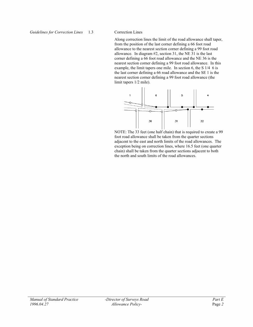
Guidelines for Correction Lines 1.3 Correction Lines
Along correction lines the limit of the road allowance shall taper, from the position of the last corner defining a 66 foot road allowance to the nearest section corner defining a 99 foot road allowance. In diagram #2, section 31, the NE 31 is the last corner defining a 66 foot road allowance and the NE 36 is the nearest section corner defining a 99 foot road allowance. In this example, the limit tapers one mile. In section 6, the S 1/4 6 is the last corner defining a 66 road allowance and the SE 1 is the nearest section corner defining a 99 foot road allowance (the limit tapers 1/2 mile).
NOTE: The 33 feet (one half chain) that is required to create a 99
foot road allowance shall be taken from the quarter sections adjacent to the east and north limits of the road allowances. The exception being on correction lines, where 16.5 feet (one quarter chain) shall be taken from the quarter sections adjacent to both the north and south limits of the road allowances.

Manual of Standard Practice -Natural Boundaries- Part E 2003.04.26 Page 1
PART E, APPENDICES Section 2
NATURAL BOUNDARIES Guidelines for the Representation of Natural Boundaries under the Surveys Act
2.1 In common law, a natural boundary at any instant is the designated natural feature as it exists at that instant, and the boundary position changes with the natural movements of the feature as long as these movements are gradual and imperceptible from moment to moment.
It is essential to designate clearly and concisely both on the plan and in the field notes, the character of any natural feature adopted as a boundary. In the case of water boundaries, except where applicable legislation, judicial decision, or existing rights are to the contrary, the bank shall be used as the feature defining the boundary.
Natural Boundaries 2.2 .1 When it has been confirmed that an adjoining owner has riparian rights, the bank of the body of water should be shown as it exists at the time of survey.
.2 If it is found that an owner does not have riparian rights, the bank should be shown according to the traverse of the river or lake upon which the title is based. Field notes of these traverses are available from the office of the Director of Surveys.
.3 If it is necessary to show the present bank and its position at the time of patent, both traverses should be shown. One should be shown in a solid black line, the other in a broken black line, in order of importance. A notation of the date of traverse and the name of the surveyor shall be shown on each.
2.3 Natural boundaries may be located by:
.1 a survey network utilizing offsets or radial measurements such that bank identification points do not exceed a 30 metre interval.
.2 by plotting the features directly from controlled aerial photographs, provided that:
.1 the scale of the photographs is as large as or larger than the scale of the final plan of survey. Enlargements may be used to fulfil this requirement only if the resolution is such that the boundary feature is sharply defined on the enlargements.
.2 the boundary is inspected on the ground by the surveyor.
.3 the position of the boundary is clearly marked on the photographs and, where it is inspected on the ground, is marked on the photograph in the course of the inspection.
.4 photo identifiable points are positively identified and are pinpricked on the photographs and surveyed on the ground in relation to the monumentation of the survey and according to the following specifications:
Manual of Standard Practice -Natural Boundaries- Part E 2003.04.26 Page 2
.1 one photo-identifiable point is to be established in the vicinity of each intersection of an artificial boundary with the natural boundary, and a tie is to be made to the natural boundary along each intersecting artificial boundary.
.2 at least three photo-identifiable points are to be established in the vicinity of the natural boundary on each photograph used, or if enlargements are used, on each 25 cm. square of the enlargement along the course of the natural boundary, and
.3 the accuracy of survey of the photo-identifiable points shall be at least the equivalent to that prescribed for surveys under the Surveys Act.
.3 Notwithstanding the above, natural boundaries may be plotted by stereoplotter provided that:
.1 the scale at which the model is viewed is as large as or larger than the final plan of survey,
.2 the boundary is inspected on the ground by the surveyor, and
.3 photo-identifiable points are pin-pricked on the photographs and surveyed on the ground according to the following specifications:
• one photo-identifiable point is to be established in the vicinity of each intersection of an artificial boundary with the natural boundary,
• at least two photo-identifiable points at each end of the series of overlaps and at least one control point at intervals not exceeding three overlaps are to be established, and
• the accuracy of survey of the photo-identifiable points shall be at least the equivalent to that prescribed for surveys under the Surveys Act.
.4 All detail transferred from a particular photograph to the plan in accordance with the above should be outlined in ink on the photograph, and the photograph should be retained by the surveyor as part of the field notes. The relevant photograph numbers must be shown on the plan. All photographs used must show date of photography and scale, and be signed and dated by the Alberta Land Surveyor responsible for the survey.

Manual of Standard Practice Part E 1996.04.27
-Guidelines for Retracements and Restorations- Page 1
PART E, APPENDICES Section 3
GUIDELINES FOR RETRACEMENTS AND RESTORATIONS The following guidelines respecting the retracement of
boundaries, and the restoration or re-establishment of monuments must be considered in the context of fundamental survey law. That is, monuments placed and intended to govern boundaries pursuant to Sections 33, 34 and 45 of the Surveys Act shall govern those boundaries if found to be in their original position. It follows that the principle of the “best evidence” of the original position of the monument shall guide the land surveyor in retracing boundaries and restoring or re-establishing obliterated or lost monuments. In other words the following guidelines must not be viewed as “prescriptive” in nature but rather supportive in arriving at a “best evidence” conclusion.
Research 3.1 Prior to undertaking a retracement survey, a thorough review of all available information pertaining to the property boundary is mandatory. Sources of documents include, but are not limited to, the following:
.1 Land Titles Office registered plans, certificates of title and other documents,
.2 Director of Surveys Office original township plans and original field notes for the township surveys and cadastral tie reports,
.3 other surveyor’s files and field notes, when known to exist and the survey has not been publicly recorded,
.4 A.E.U.B. well site plans and licensed pipelines,
.5 Bulletin 38 - describes original monuments circa 1871 to 1917
.6 Land Administration Division for crown dispositions.
Hierarchy of Evidence 3.2 When an Alberta Land Surveyor is employed to retrace original or existing surveyed property boundaries, it is essential that a thorough field investigation is made to unearth evidence as to the position of the boundaries as originally surveyed. The hierarchy of evidence regarding boundaries is:
.1 natural boundaries, or evidence of same,
.2 original monuments or traces of same,
.3 fences or evidence of possession reasonably dating back to the original survey,
.4 measurements as shown on plans of previous surveys.
Verbal Evidence 3.3 Section 13 of the Surveys Act empowers Alberta Land Surveyors to examine witnesses under oath in relation to determining the true and original position of survey monuments which have been destroyed. Appropriate testimony from a reliable witness having first hand knowledge may be the best evidence available in retracement surveys. The evidence should be transcribed in writing and signed under oath by the witness.

Manual of Standard Practice Part E 1996.04.27
-Guidelines for Retracements and Restorations- Page 2
Coordinates 3.4 Coordinates on property corners and ties to Alberta Survey Control Markers may be useful evidence of original monument locations and are deemed to be measurements in the hierarchy of evidence.
Conflicting Evidence 3.5 Positional conflicts arising from plan dimensions, monuments on the ground, or other sources are not uncommon in conducting retracement surveys. It is the responsibility of the Alberta Land Surveyor to discharge his duty in an unbiased manner in resolving such conflicts. The surveyor should consider the following in resolving such conflicts:
.1 Property lines established on a registered subdivision or original township survey plan cannot be altered by subsequent plans, although resubdivision can be used to effect new boundaries between consenting owners.
.2 Given ambiguity or conflict within a single plan, the “intent” of the original survey should be considered as a guide to the surveyor in effecting re-establishment.
.3 The advice of the Director of Surveys, experienced surveyors, or the original surveyor should be sought in difficult cases.
.4 If a boundary conflict cannot be resolved by the surveyor, it may be necessary to involve the Board of Investigation pursuant to Section 9 of the Surveys Act or the courts. In this event, the surveyor would assume the role of expert witness.
Witness Monuments 3.6 When establishing a section or quarter section corner from a witness monument placed subsequent to 1890, the said corner shall be defined by producing the line through the witness monument from the nearest section or quarter section corner on the same side of the witnessed corner. The corner in question shall be placed at the distance indicated for the witness monument. Prior to 1890, witness monuments were not required to be placed on a surveyed line and corner establishment should be based on the nature of the evidence.
Original Notes 3.7 When searching for original section or quarter section corner monuments, the original township survey notes may be indispensable. Such information as direction of survey and ties to topographic features may assist in a thorough search for evidence. Copies of these field notes are available from the Director of Surveys.
Lost Monuments in Subdivisions 3.8 Before February 16, 1912, all lot and block corners on subdivision surveys were required to be monumented. Therefore, when retracing lot boundaries originally created before that date, and after June 9, 1988, it is essential to search for original monuments at all corners.

Manual of Standard Practice Part E 1996.04.27
-Guidelines for Retracements and Restorations- Page 3
Between February 16, 1912 and June 9, 1988, posting was required only for block outlines, deflections, and those lot corners falling on a curvilinear block boundary. Therefore, when a surveyor is to re-establish a lost monument at a lot corner within a plan originally surveyed between these dates, the positions of the property lines are governed by the plan dimensions in relation to the block corners, except for corners on curvilinear boundaries. Proportioning from the original block corner monuments or from the re-established positions of these monuments is generally required.
Lost Monument Procedure on Townships
3.9 When monuments on original township survey boundaries cannot be restored from traces remaining on the ground of the original monument, from other physical evidence, or testimony by witnesses, then as a last resort the surveyor may proceed to re-establish the monument by measurement from other monuments which are connected to it by survey.
If the re-establishment uses other monuments from the original township survey, the surveyor shall consider the intent and sequence of the original survey.
If the lost monument is in the interior of the township, generally other monuments north and south of the lost corner should be used. If the lost monument is on the exterior boundary of the township, other monuments on either side of the lost corner on the same township boundary should be used. Re-establishment of quarter corners on east-west section boundaries in the interior of the township should consider the relationship to section corners on either side.
It is the responsibility of the surveyor to assess all available evidence, including other monuments placed on subsequent plans, when re-establishing a lost monument. The re-establishment should be performed using the best evidence available, while additional ties should be made to other monuments to validate the re-establishment.
When re-establishing lost corners in original townships surveys, due weight shall be given to the bearings as shown on the official or registered plan.
Monuments to Restore 3.10 All damaged or obliterated monuments used in a survey, whether urban or rural, should be restored. Pits, mounds and/or trenches on original township surveys, however, shall not be reconstructed or restored unless so instructed by the Director of Surveys.
Curve Re-establishment 3.11 Section 45(1)(a)(i) and Section 45(2) of the Surveys Act should be followed to define curvilinear property boundaries. The radius shown on the original plan of survey and the position of the original monuments shall be used. The chord or radial bearing should be shown on the plan.

Manual of Standard Practice -Standard Affidavits- Part E 2003.04.26 Page 1
PART E, APPENDICES Section 4
STANDARD AFFIDAVITS Revised 2003.04.26 Most plans are required to contain some form of signature from
the Alberta Land Surveyor who is responsible for the plan. This section contains the standard affidavits/certifications required on plans that are not registerable at the Land Titles Office.
Plans that are submitted for registration at the Land Titles Office also require various signatures, affidavits and/or other approvals. The Land Titles Office Procedures Manual should be consulted to assist in determining which signatures, affidavits and/or other approvals are required for the type of plan that is being prepared and submitted for registration. The Land Titles Office Procedures Manual is available on the internet at http://www3.gov.ab.ca/gs/.

Manual of Standard Practice Part E 2001.04.21
-Alberta Land Surveyor’s Real Property Report Certification,
Schedule “A”- Page 1
PART E, APPENDICES Section 4
STANDARD AFFIDAVITS
SCHEDULE “A”
ALBERTA LAND SURVEYOR’S
REAL PROPERTY REPORT CERTIFICATION
The plan prepared as part of the Alberta Land Surveyor’s Real Property Report shall include a certification in the following form:
(Firm name and address)
ALBERTA LAND SURVEYOR’S REAL PROPERTY REPORT
To: [Client] (the “Client”)
Re: [Legal Description, Address, Municipality] (the “Property”)
Date of Survey: ______________________________________
Date of Title Search:___________________________________
(A copy of which is attached hereto)
Certification: I hereby certify that this report, which includes the attached plan and related survey, was prepared and performed under my personal supervision and in accordance with the Manual of Standard Practice of the Alberta Land Surveyors’ Association and supplements thereto. Accordingly within those standards and as of the date of this report, I am of the opinion that:
1. the plan illustrates the boundaries of the property, the improvements as defined in Part D, Section 7.6 of the Alberta Land Surveyors’ Association’s Manual of Standard Practice, registered easements and rights-of-way affecting the extent of the title to the property;
2. the improvements are entirely within the boundaries of the property, [except ____________________________________________________________(to be used if applicable)]
3. no visible encroachments exist on the property from any improvements situated on an adjoining property, [except ____________________________________________________________ (to be used if applicable)]
4. no visible encroachments exist on registered easements or rights-of-way affecting the extent of property, [except ____________________________________________________________(to be used if applicable)]
[INSERT OTHER MATTERS HERE] - to be used for extraordinary circumstances that should be noted.]
Purpose: This Report and related plan have been prepared for the benefit of the Property owner, subsequent owners and any of their agents for the purpose of (a land conveyance, support of a subdivision application, a mortgage application, a submittal to the municipality for a compliance certificate, etc.). Copying is permitted only for the benefit of these parties, and only if the plan remains attached. Where applicable, registered easements and utility rights of way affecting the extent of the property have been shown on the attached plan. Unless shown otherwise, property corner markers have not been placed during the survey for this report.
The attached plan should not be used to establish boundaries due to the risk of misinterpretation or measurement error by the user.
The information shown on this Real Property Report reflects the status of this property as of the date of survey only. Users are encouraged to have the Real Property Report updated for future requirements.

Manual of Standard Practice Part E 2001.04.21
-Alberta Land Surveyor’s Real Property Report Certification,
Schedule “A”- Page 2
Dated at _________________________________, Alberta.
This ______________ day of ____________________, 20__.
____________________________
John L. Surveyor, A.L.S.
(copyright reserved)
This document is not valid unless it bears an original signature (in blue ink) and a (survey company) permit stamp (in red ink)[If Applicable].
[On the plan insert the following:
This plan is page 2 of a Real Property Report and is ineffective if it is detached from page 1.]

Manual of Standard Practice Part E 2007.04.28
-Certification, Schedule “B”- Page 1
PART E, APPENDICES Section 4
STANDARD AFFIDAVITS
SCHEDULE “B”
CERTIFICATION
I, _____________________________, Alberta Land Surveyor, of ___________________________, Alberta, certify that the survey represented by this plan is true and correct to the best of my knowledge, has been carried out in accordance with the Alberta Land Surveyors’ Association Manual of Standard Practice, and the field survey was performed between the _____ day of _______________, 20___ and the _____ day of _______________, 20___.
_____________________ ____________________ _____________________
Alberta Land Surveyor Date Signed Witness (name of witness)
Revised 2007.04.28 The change to the Certification came into effect on May 15, 2007.

Manual of Standard Practice Part E 2004.04.24
-Geometrical Deformation Survey Guidelines- Page 1
PART E, APPENDICES Section 5
GEOMETRICAL DEFORMATION SURVEY GUIDELINES Geometrical deformation surveys are performed to detect and measure movements and can be used to complement more traditional deformation measurements usually performed by structural and geotechnical engineers. Practitioners are advised to consider the following guidelines when undertaking a geometrical deformation survey.
1. Expectations/Requirements • Relative or absolute deformation survey
• Accuracy required to detect the geometrical displacement
• Observation period and frequency
• External effects/physical attributes of the deformable body
2. Monitoring Network Design • Instrumentation
• Configuration (geometry, Datum defects)
• Observations (Number, Type, Geotechnical)
• Pre-analysis with appropriate observational weights
• Environmental influences
3. Monumentation • Appropriate reference and object monuments/targets
• Stability of reference and object monuments/targets
• Logistics and site conditions
4. Equipment • Calibration - techniques, frequency, analysis and implementation
• Adjustment
5. Observation Procedures • Standardized between epochs
• Environmental factors
• Data monitoring and recording
• QA/QC and confirmation of expected results
6. Data Analysis • Preprocessing and reduction
• Reduction network adjustment
• Practical observation weighting scheme
• “Best” definition of a common datum
• Rigorous geometrical deformation analysis
7. Reporting • History
• Methodology
• Results of individual epochs
• Geometrical displacements
• Quality of the geometrical displacements
• Conclusions

Manual of Standard Practice
-Process And Obligation To Register Plans On Metis Settlements With Metis Settlements Land Registry-
Part E
2004.04.24 Page 1
PART E, APPENDICES Section 6
PROCESS AND OBLIGATION TO REGISTER PLANS ON METIS SETTLEMENTS WITH METIS SETTLEMENTS LAND REGISTRY
Added 2004.04.24 When conducting surveys on Metis Settlements, the obligation to
register those plans with the Metis Settlements Land Registry is the same as the obligation to register plans at Land Titles. Clients requesting surveys on Metis Settlements should be advised that the plan has no effect unless registered with the Metis Settlements Land Registry. For information purposes only, plans may also be filed/registered at Land Titles. Plan requirements are similar to those of Land Titles with a few exceptions. The Registry block refers to the Metis Settlements Land Registry, the plan must be on mylar and it is preferred that the Alberta Land Surveyors' affidavit be on the plan rather than separate. More detailed plan requirements are found in Sections 86 and 87 of the Metis Settlements Land Registry Regulation. Further information can be found at http://www.metis-settlements.org.

Manual of Standard Practice -Index of Reference Information- Part E 2005.04.23 Page 1
PART E, APPENDICES Section 7
INDEX OF REFERENCE INFORMATION
Added 2005.04.23
In addition to the material contained in the Manual of Standard Practice, there is other reference information with which Alberta Land Surveyors and their staffs should be familiar.
Please include the relevant reference information depending on your type of practice in your Manual of Standard Practice.
This reference information is located on the Alberta Land Surveyors' Association website and includes (but is not limited to the following):
Commitment to Property Damage Mitigation (Best Practices) — http://www.alsa.ab.ca/bestpract.htm#Commitment
Boundary Surveys Act — http://www.alsa.ab.ca/historical.htm#Boundary
Bulletin 38 — http://www.alsa.ab.ca/historical.htm#Bulletin
Control Survey Standards — http://www3.gov.ab.ca/srd/land/dos/Docs/gpsrep.pdf
Court Decisions — http://www.alsa.ab.ca/court.htm
Dominion Re-surveys Act — http://www.alsa.ab.ca/historical.htm#Dominion
Good Practice Resolutions: 1980 to 1988 — http://www.alsa.ab.ca/historical.htm#GPR:1980
Good Practice Resolutions: 1959 to 1977 — http://www.alsa.ab.ca/historical.htm#GPR:1959
History of Re-establishing from Road Plans (1942 Surveys Act) — http://www.alsa.ab.ca/pdf/historical/historyroadplans.pdf
Indian Reserves Surveys — http://www.alsa.ab.ca/historical.htm#Indian
Land Surveyors Act: 1910 to 1981 — http://www.alsa.ab.ca/historical.htm#LSA
Manual of Instruction for Survey of Canada Lands — http://www.alsa.ab.ca/historical.htm#Manual
Manual of Standard Practice — http://www.alsa.ab.ca/historical.htm#MSP
Oil & Gas Related Legislation & Information — http://www.alsa.ab.ca/historical.htm#Oil
Practice Review Board Interpretive Bulletins — http://www.alsa.ab.ca/interpretation.htm
Surveys Act: 1922 to 1987 — http://www.alsa.ab.ca/historical.htm#SA
Practitioners should use the search feature on the ALSA website to find relevant articles that were printed in ALS News or other ALSA publications.
Manual of Standard Practice Definitions 1996.04.27
-Definitions- Page 1
DEFINITIONS
This glossary explains the terms used by Alberta Land Surveyors in their professional practices.
Additional related definitions are found in the Surveys Act, Land Titles Act, Municipal Government Act, and other related legislation.
A
Accuracy The degree of conformity of closeness of a measurement to the true value. (Mikhail & Gracie, Analysis and Adjustment of Survey Measurement)
Azimuth The azimuth of a point B from another point A is the angle formed by the vertical plane containing A and B with the plane of the astronomical meridian passing through A, such angle being reckoned from north, around through east, south and west, to 360 degrees, east being 90 degrees, south 180 degrees, west 270 degrees, and north 360 or 0 degrees. It follows that, except in the case of a meridian or the equator, the azimuth of a straight line changes as the initial point moves along the line and that direction is not defined by an azimuth unless the initial point is specified or implied.
B
Bearing The bearing of a point B from another point A is the angle formed by the vertical plane containing A and B with the plane of a fixed astronomical meridian, which may or may not be the astronomical meridian passing through A, such angle being reckoned like the azimuth from north around through east, south and west to 360 degrees. It follows that a straight line has the same bearing at all its points, but except in the case of a meridian or the equator, a direction is not defined by a bearing unless the meridian to which the bearing is referred is specified or implied.
Bearing Tree A tree with a blaze approximately 1 metre above ground facing a monument.
Boundary A boundary is a line determining the limits of a parcel and shall be defined by:
• In the case of surveyed parcels by the original monuments, or other undisputed monuments governing the corners thereof. For the purpose of this definition a corner shall be defined as a deflection point, end or beginning of curve, or any point that was defined by the original survey of said parcel. Original monuments shall be deemed to be those monuments purported to have been placed during the original survey of the parcel.
• In the case of unsurveyed parcels by those lines that are, or may be, determined by reference to monuments of public record placed in accordance with the Surveys Act.
•
A boundary, as it relates to the Surveys Act, is a line between two monuments depicting a separation between two parcels. A line may be a straight line, curved line or a series of connected points used to depict a natural boundary. Parcels may be land surfaces, sub-surface regions or airspace lying above parcels.
C
Calculated “Calculated” data is information derived by computation from sources which may not have been measured in entirety by the Surveyor who displays such information.

Manual of Standard Practice Definitions 1996.04.27
-Definitions- Page 2
D
Disturbed monument A disturbed monument is one that has been moved other than by an Alberta Land Surveyor in the course of his duty and that can be proved beyond reasonable doubt to have been moved from its original position.
E, F, G, H
I
Integrated Survey Any survey, the data from which forms part of the geographical positioning system.
J, K
L
Lost monument A lost monument is one whose position can be re-established only by its bearing and distance from some other monument or monuments to which it had previously been connected by survey.
M
Monument A monument, as it related to the Surveys Act, means a brass tablet, iron post, wooden post, mound, pit or trench or anything else used by a Surveyor to mark a boundary, corner or line. (Section 1[m], Surveys Act)
N
Natural Boundary A natural boundary, as it relates to the Surveys Act, is a line determined by a Surveyor, by any method that has the affect of accurately determining its location at the time of survey, related to the surveyed boundaries of the affected parcel.
When surveying a natural boundary that is a body of water, the Surveyor shall determine the position of the line where the bed and shore of the body of water ceases and the line shall be referred to as the bank of the body of water.
The “bed and shore” of a body of water shall be the land covered so long by water as to wrest it from vegetation or as to mark a distinct character on the vegetation where it extends into the water or on the soil itself. (Sec. 17[1][2][3], Surveys Act)
The “right” or “left bank” of a stream is that bank which is on the right or left side of the bed as the case may be when the observer is looking downstream. The bank of a body of water is the limit or edge of the bed of the body of water.
O
Obliterated monument An obliterated monument is one that can be restored with confidence from traces remaining on the ground of the original monument or from other physical evidence of the position of the original monument.
P
Parcel A parcel is an area of land that has one or more boundaries surveyed in accordance with the Surveys Act, and which is capable of having an interest or right granted and registered in the Land Titles Office or filed in the Metis Settlements Registry.
Precision The degree of closeness or conformity of repeated measurements of the same quantity to each other (Mikhail & Gracie, Analysis and Adjustment of Survey Measurement)
Manual of Standard Practice Definitions 1996.04.27
-Definitions- Page 3
Public Record A public record includes a plan on record with Land Titles, Alberta Sustainable Resource Development, Canada Lands Survey Records, or any other federal or provincial agency.
Q
R
Re-establish To re-establish means to determine the position of a lost monument.
Reference monument A mark, other than a monument or survey control marker, set in the ground as a reference to the position of a boundary or other lines not marked by monuments under section 47 of the Surveys Act.
Restoration survey A restoration survey is a survey made to restore the obliterated monuments of a previous survey.
Resurvey A resurvey is the survey of a previously-surveyed boundary made to effect changes in, or corrections to, the previous survey or to re-establish lost monuments or to place additional monuments on the boundary. A resurvey will always include a retracement of the boundary and often also the restoration of obliterated monuments.
Retracement Survey A retracement survey is a survey of the existing monumentation of a previously surveyed boundary in order to determine the bearings and distances between the monuments.
S
Surface Improvement (with respect to wellsite surveys)
A surface improvement is defined as a railway, pipeline, or other right of way, road allowance, surveyed roadway, dwelling, industrial plant, aircraft runway or taxiway, building used for military purposes, permanent farm building, school or church (as defined by the EUB’s Directive 056).
Surveyed Boundary A surveyed boundary shall be that boundary defining the limits of a parcel that has been surveyed in accordance with the provisions of the Surveys Act and is shown on a plan of public record.
Surveyed Lines Except as noted in Cancelled, Abandoned Plans in the Right-of-Way Surveys section, surveyed lines are defined as:
• any line shown to be surveyed on a plan registered in the Land Titles Office,
• blind lines whether actually surveyed on the original township survey or not.
Surveyor For the purposes of this document, surveyor means an Alberta Land Surveyor as defined by the Land Surveyors Act.
T
Theoretical Section Boundary A line that would define the boundary of a section if the section were surveyed in accordance with Part 2 of the Surveys Act.
U
Uncertainty The range within which it is expected the error of measurement will fall. (Mikhail & Gracie, Analysis and Adjustment of Survey Measurement)
Unsurveyed Territory Those lands in Alberta which have not been surveyed, and for which there is no official plan, within the meaning of Part 2 of the Surveys Act.
V

Manual of Standard Practice Definitions 1996.04.27
-Definitions- Page 4
W
Well A well to be drilled for any purpose provided for in the Oil and Gas Conservation Regulation (Alta. Reg. 151/71).
X, Y, Z
Manual of Standard Practice Index 2007.04.28
-Index- Page 1
INDEX
A Abandoned Right-of-way Plan D4.4.1 Absolute E5.1 Access road D5.10, D5.10.1, D5.2.2 Accuracy C1.1, C1.2, C1.3, C1.5, C2, C2.1, C2.2, C5.7.3, D1.2.1, D5.10.2, D5.10.4, D5.8.6, D9.4, E2.3.2, E2.3.3, E5.1 Act AA, B(4), B(5), B(6), B(7), B(8), B1, B2(1), B2.1, B2.2, B3.1.1, B3.1.2, B3.1.3, C1.1, C1.4, C2, C3.1.1, C3.1.2, C3.1.3, C3.1.4, C3.1.5, C3.2, C3.3, C3.4.2, C3.5, C3.8, C5.1, C5.5, C5.7.1, C5.8, C5.8.2, D1, D1.2.1, D1.2.2, D10, D2, D2.1, D2.2.2, D2.2.3, D4, D4.2, D4.7, D4.8.1, D4.9, D5, D5, D5.1.1, D5.1.2, D5.2.1, D5.3, D5.7, D5.8, D5.8.3, D5.8.4, D7.3, D7.5.11, D7.7.1, D7.7.2, D8, Def, DefB, DefM, DefN, DefP, DefR, DefS, DefS, DefS, DefT, DefU, E2.1, E2.3.2, E2.3.3, E3, E3.11, E3.3, E3.5, EA, EB, E5, E5.5, E5.6, E7 Adjustment C1.1, C2.3, DefA, DefP, DefU, E5.6 Advertisement B(6), B2.1 Aerial photograph E2.3.2 Affidavit E4, E6 Alberta Energy and Utilities Board D4.4.2, E3.1
Alberta Survey Control C1.4, D5.1.2, D5.10.2, D5.8.4, D5.9.1, E3.4 Alberta Survey Control Marker D5.1.2, D5.8.4, D5.9.1, E3.4 Alberta Sustainable Resource Development D5.8, D5.8.1, DefP, E7 Alberta Township System D1.2.3, D5.10.2 Ambiguity C3.1.5, E3.5 Angular tie D1.3 Area B(4), B1, C3.3.1, C3.5, D5, D5.9.1, D5.9.2, D7.6.9, D9.6, DefP Artificial boundary E2.3.2, E2.3.3 As-built D4.10, D5.10, D5.10.1, D5.9.9 As-constructed D4.10 Astronomic D1.2.3, D10.2, DefA, DefB Astronomical meridian D1.2.3, D10.2, DefA, DefB Astronomical observation D1.2.3
B Bank DefN, E2.1, E2.2.1, E2.2.2, E2.2.3, E2.3.1 Bearing C3.3.3, C5.2, D1.2, D1.2.1, D1.2.2, D1.2.3, D1.4, D10.2, D4.2, D5.10.1, D5.10.3, D5.10.4, D5.8.5, D5.8.6, D7.5.7, DefB, DefL, DefR, E3.11, E3.9 Bearing Tree C3.3.3, D5.10.1 Beginning of curve DefB Benchmarks C1.5, D5.9.1 Best evidence D4.10, D4.9, D5.8, E3, E3.3, E3.9 Blaze DefB Blind Line D4.1.3, DefS Block D1.4, D5.9.4, E3.8, E6 Block corners E3.8 Board of Investigation E3.5 Boundaries AA, B1, C3.4.1, C3.4.2, C3.6, D1.3, D1.4, D10.1, D4.4.1, D5.1.1, D5.1.2, D5.10.1, D5.10.2, D5.2.1, D5.3.1, D5.8, D5.8.2, D5.8.3, D5.8.4, D6.1, D6.2, D7.3, D7.4, D7.5.8, D7.6.1, D7.7.1, D7.7.2, D8, D9.4, DefN, DefP, E1.2, E2.1, E2.3, E2.3.3, E3, E3.11, E3.2, E3.5, E3.8, E3.9, EA

Manual of Standard Practice Index 2007.04.28
-Index- Page 2
Boundary B(3), C1.1, C2, D1.4, D2.2.2, D4.1.3, D4.2, D4.5, D4.8.3, D5.2.1, D5.2.2, D5.8.1, D6.3, D7.5.7, D7.7.1, D8, DefB, DefM, DefN, DefR, DefR, DefR, DefS, DefT, E2.1, E2.3.2, E2.3.3, E3.1, E3.5, E3.8, E3.9, E7 Boundary Surveys Act D8, E7 Brass tablet C3.2, DefM Building D7.6.1, DefS Bulletin 38 E3.1, E7 C Cadastral Tie Reports E3.1 Calculated D4.5, D5.2.2, D7.7.3, DefC Calculated distance D4.5, D7.7.3 Calibration D5.9.1, E5.4 Cancelled Subdivision Plan D4.4.1 Caveat D5 Centre line of rail D4.10, D4.9 Centre line of track D4.8.2, D4.8.4 Certificate of Title D7.4 Chain E1.1.2, E1.1.3, E1.3 Check-tie D9.8
Chord D1.4, E3.11 Church DefS Circular curve C3.6, D1.4, D4.8.2, D4.8.3 Closure B(7), C1.1, C1.2, C1.3, C1.4, C1.5, C5.2, C5.3, C5.3.1, C5.7.3, D1.5, D4.6 Combined Factor D1.2.2 Common Law E2.1 Compliance AA, B(3), EA Concrete nail C3.1.3 Condominium Plan D3 Confidence region C1.1, C1.2, C1.3, C1.5 Configuration E5.2 Conflict AA, B(2), D2.2.2, D5.8, D7.6.9, E3.5 Construction drawing D9.1, D9.2, D9.3 Construction layout survey D9 Coordinate position C5.8.1, C5.8.1, C5.8.2, C5.8.2, D2.2.2, D2.2.2 Coordinates C5.3, D1.2, D1.2.2, D1.2.3, D2.2.4, E3.4 Copyright symbol D7.5.11
Correction Line E1.1.3, E1.2, E1.3 Countersunk C3.5 Courts E3.5 Critical boundaries D7.7.2 Crown C3.1.2, C3.2, E3.1 Crown disposition E3.1 Curves D1.4, D4.11, D4.8.2, D5.9.5 CVD 28 D1.2 D Datum C1.5, D1.2, D1.2.2, E5.2, E5.6 Deflection C3.4.2, D4.1.3, DefB, E3.8 Deformation measurement E5 Delayed posting D2.1, D2.2 Density C5.7.2 Descriptive Plan D6, D6.1, D6.3 Destroyed C3.11, D2.2.2, E3.3 Digital return C4 Director of Surveys C3.11, C3.2, C5.3, D2.2.3, D5.1.2, D5.8.4, D8, E1.1, E2.2.2, E3.1, E3.10, E3.5, E3.7

Manual of Standard Practice Index 2007.04.28
-Index- Page 3
Disturbed C3.11, DefD E Easement D7.5.13, EA Ellipsoid D1.2 Encroachments D6.1, D7.7.2, EA End of curve D4.1.3 Environmental condition C4.2.3 Epoch E5.5, E5.7 Error of closure C5.3 Evidence C3.4.1, C4.2.6, D4.10, D4.9, D5.8, D7.5.9, D7.7.1, DefO, E3, E3.2, E3.3, E3.4, E3.6, E3.7, E3.9 Existing Right-of-way D4.1.2 Expert Witness E3.5 F Facility D5.2.1, D5.2.2 Fences D7.6.9, E3.2 Field inspection D6.1, D6.2, D6.3, D7.8 Field notes C4, C4.1.1, C4.2, C4.3, D7.5.10, D9.9, E2.1, E2.2.2, E2.3.4, E3.1, E3.7
G Geographical positioning system DefI Geometrical deformation survey E5 Geometrical displacement E5.1, E5.7 Geotechnical engineers E5 Global Positioning System C2, C2.1, C2.2, C2.4, E7 Grid Bearing C5.2, D1.2, D1.2.2 GRS 80 D1.2 H Hierarchy of evidence E3.2, E3.4 Horizontal accuracy C1.5 I Improvement D6.1, D7.1, D7.2, D7.5.4, D7.5.5, D7.6, D7.7.2, DefS, EA Indian Reserve E7 Instrumentation E5.2 Integrated C5.1, C5.4, D2.2.1, D5.8.4 Integration C5.2 Intent C1.1, C2, D6.1, E3.5, E3.9
Intersection C3.4.1, C3.4.2, D1.3, D4.1.3, D4.2, D5.2.2, E2.3.2, E2.3.3 Iron Bar C3.9 Iron post C3.1.1, C3.1.2, C3.1.3, C3.10, C3.3, C3.7, D4.7, D4.8.4, DefM J, K Kinematic C2.4 L Lake E2.2.2 Land Administration Division E3.1 Land Surveyors Act AA, DefS, E7 Land Titles Act C5.1, D2, D2.2.2, Def Land Titles Office C3.8, D1, D1.2, D2.2.2, D4.4.2, D5.3.4, DefP, DefS, E3.1, E4 Lanes D7.6.5 Lead plug C3.1.3 Least Squares C1.1, C1.2, C1.3, C1.5, C5.7.3 Legal description D7.5.1, D7.5.2 Legend C3.7, D1.2.2, D1.2.3, D5.9.5, D7.6.2, D7.6.9 Licensee D5.6.1

Manual of Standard Practice Index 2007.04.28
-Index- Page 4
LOC AA, C3.1.5, C4.2.1, C5.8.2, D1.4, D4.10, D4.8.4, D4.9, D5.1.1, D5.1.2, D5.10, D5.10.1, D5.3, D5.3.2, D5.8, D5.8.3, D5.8.4, D5.9.4, D6.3, D7.2, D7.3, D7.5.9, D7.7.1, D9.6, D9.7, DefN, E2.3, E3.4, E3.8, E6, E7 Logistics C4.4.1, E5.3 Logo B2.2 Lost monument C3.10, C4.2.6, D4.7, DefL, DefR, DefR, E3, E3.8, E3.9 Lot E2.3.2, E2.3.3, E3.8 M Manual of Standard Practice D1.2.2, D5.7, EA, EB, E7 Marker Condition Report C3.11 Marker post C3.3, C3.3.1, C3.3.2, C3.3.3, C3.3.4, C3.3.5, D4.7, D5.10.1 Markings C3.10, C3.7, C5.5 Measurement C1.1, C1.1, C1.4, C1.4, C2, C2, C4.1.1, C4.1.1, C4.4.3, C4.4.3, C5.2, C5.2, C5.6, C5.6, D1.3, D1.3, D5.8.7, D5.8.7, DefA, DefP, DefP, DefU, E2.3.1, E2.3.1, E3.2, E3.2, E3.4, E3.4, E3.9, EA, E5, E5 Meteorological C4.2.3 Methodology D9.4, E5.7 Metis Settlement D8, DefP, E6
Misclosure C1.1, C1.2, C1.3, C1.5 Monument C1.1, C2.4, C3.1.4, C3.1.5, C3.10, C3.2, C3.3.4, C3.4.1, C3.4.2, C3.5, C3.8, C3.9, C4.2.5, C4.2.6, C5.1, C5.6, C5.7.2, C5.8.1, C5.8.2, C5.7.3, D1.2.3, D2.2.1, D2.2.2, D2.2.3, D2.2.4, D4.1.1, D4.1.2, D4.1.3, D4.2, D4.6, D4.7, D5.1.1, D5.1.2, D5.10.1, D5.10.2, D5.3.2, D5.3.3, D5.3.4, D5.7, D5.8, D5.8.1, D5.8.2, D5.8.3, D5.8.4, D5.9.3, D5.9.5, D5.9.9, D7.3, D7.5.8, DefB, DefB, DefD, DefL, DefM, DefO, DefR, DefR, DefR, DefR, DefR, E2.3.2, E3, E3.1, E3.10, E3.11, E3.2, E3.3, E3.4, E3.5, E3.6, E3.7, E3.8, E3.9, E5.3 Monumentation C3.9, D2.2.2, DefR, E2.3.2 Mound DefM, E3.10 Municipal address D7.5.1 Municipal Government Act D2, Def Municipality D7.5.1, D7.6.1, EA N National Park D8 Natural boundaries C3.6, D6.3, DefB, DefN, E2.1, E2.3, E2.3.2, E2.3.3, E2.3.3, E3.2 Network adjustment C2.3, E5.6 North American Datum D1.2 Notation D1.1, E2.2.3
O Obliterated monument C3.10, DefO, DefR, E3.10 Observation C1.1, C1.2, C1.3, C1.4, C1.5, C2.4, C4.1.1, C4.2.1, C4.2.4, C4.4.1, D1.2.3, D2.2.1, E5.1, E5.2, E5.6 Observation period E5.1 Observation procedure C4.4.1 Official plan DefU Official Township Plan E1.1.1, E1.1.3 Offsets E2.3.1 Oil and Gas Conservation Regulation D5, DefU P Parcel D1.4, D4.5, D5.2.1, D6.1, D7.2, D7.3, D7.4, D7.5.1, D7.5.2, D7.5.7, D7.6.1, D7.6.3, D7.6.5, D7.6.6, D7.7.1, DefB, DefN, DefP, DefS Parts Per Million C1.1 Patented Land D5 Perimeter monumentation D2.2.2 Permanent structure C4.2.5 Permit number C3.7 Permit stamp D7.9, EA

Manual of Standard Practice Index 2007.04.28
-Index- Page 5
Physical evidence D5.8, DefO, E3.9 PIL B2(1), C4 Pin-prick E2.3.3 Pipeline D4, DefS, E3.1 Pits D4.7, E3.10 Plan of survey D1.1, D1.2, D1.2.3, D4.5, D5.3, D5.9.9, E2.3.2, E2.3.3, E3.11 Plans AA, B(2), C5.8, D1, D1.2, D1.2.2, D1.2.3, D1.4, D2, D2.2.2, D2.2.4, D3, D4, D4.4.1, D4.8.1, D4.9, D5.1.2, D5.10.2, D5.10.6, D5.6.2, D5.8, D5.8.9, D5.9.8, D6, D7.7.3, D9.2, DefS, E1.1.1, E3.1, E3.2, E3.5, E3.9, E4, E6, E7 Point of Curvature C3.4.2, D4.8.4 Precision C1.1, D1.4 Preprocessing E5.6 Prior survey D7.7.3 Projection D1.2, D1.2.2, D7.6.1 Property Lines D7.6.5, D7.6.9, E3.8 Proportioning E3.8 Province of Alberta C3.2 Provincial Boundaries D8
Provincial Parks D8, D8 Public Land Disposition D5.10, D5.10.5, D5.8, D5.8.10 Q Quarter Section C3.10, C3.4.1, D4.2, D4.5, E1.2, E1.3, E3.6, E3.7 R Radial bearing D1.4, E3.11 Radius D1.4, E3.11 Railway D4, D4.8.1, D4.8.2, D4.8.3, D4.8.4, DefS Railway limit D4.8.2 Raw data C4.4.1 Re-establish B1, C3.10, C3.4.1, C5.8.1, D1.1, D4.7, DefL, DefR, DefR, E3, E3.5, E3.8, E3.9, E7 Re-established Monument C5.8.1, D4.7 Re-establishment E3, E3.5, E3.9 Re-subdivision E3.5 Real Property Report B(2), D7.2, D7.3, D7.4, D7.5, D7.5.3, D7.8, D7.9, EA, EA, E7 Reconstructed E3.10 Records C4.1.1, C4.4, D4.4.2, DefP
Reference B2.1, C3.1.5, C3.3, C3.5, C5.7.2, C5.8.1, C5.7.3, D1.2, D1.2.2, D1.2.3, D10.2, D2.2.1, D2.2.4, D5.10.3, D5.8.5, DefB, DefR, E5.3, E7 Reference meridian D1.2.2, D1.2.3, D10.2 Reference monument C3.1.5, C5.7.2, C5.8.1, C5.7.3, D2.2.1 Reference network D2.2.1 Registration C3.7, D1, D2.2.2, D2.2.3, D3, D4, D5.3.4, D6, E4 Registration number C3.7 Regulation B(5), D2, D2, D2.2.2, D2.2.2, D5, D5, DefU, E6 Relative C1.1, C1.2, C1.3, C1.5, D1.2.3, D10.2, D5.9.1, E5.1 Reserve B(3), C4.1.2, D8, EA, E7 Resolution E2.3.2, E7 Restoration D1.1, DefR, DefR, E3 Restored C4.2.5, D4.7, DefO, E3.10, E3.9 Retracement D1.1, DefR, DefR, E3, E3.1, E3.3, E3.5 Right-of-way C3.3.2, D1.4, D4.1.1, D4.1.2, D4.2, D4.3, D4.4.1, D4.8.1, D4.8.3, D4.8.4, DefS Right-of-way Survey C3.3.2, D4.3, D4.8.1

Manual of Standard Practice Index 2007.04.28
-Index- Page 6
Riparian Rights E2.2.1, E2.2.1, E2.2.2, E2.2.2 River E2.2.2 Road Allowance DefS, E1.1, E1.1.1, E1.1.3, E1.1.4, E1.2, E1.3 Roads C3.3.2, D4, D4, D4.1.3, D4.1.3, D4.2, D4.5, D4.7, D5.10, D5.10.1, D5.2.2, DefS, E1.1, E1.1.1, E1.1.3, E1.1.4, E1.2, E1.3, E7 Runway DefS S Scale C1.1, D1.2.2, E2.3.2, E2.3.3, E2.3.4 Setback D7.6.1, D7.7.2 Settlement D8, DefP, E6 Sideyard D7.7.2 Signage B2.2 Software C4.4.2 Spiral Curve D4.11, D4.8.2, D4.8.3 Spiral Curve Replacement Table D4.11 Statutory Iron Post C3.1.1, C3.1.3, C3.10 Steel bar C3.1.3 Stereoplotter E2.3.3
Stream D5, DefN Streets D7.6.5 Subcontractor B2.2, B3.1.1, B3.1.2, B3.1.3 Subdivision D1.4, D2, D2.1, D2.2, D2.2.2, D4.4.1, D6.1, E3.5, E3.8, EA Survey control marker C3.11, C5.1, C5.2, C5.3, C5.3.1, C5.5, C5.6, C5.7.1, C5.7.2, C5.8.1, C5.7.3, DefR Survey control marker condition report C3.11 Surveyed Territory C3.3.3, D1.2.3, D10, D5.1.1, D5.1.2, D5.3, D5.8.3, D5.8.4 Surveyor's corporation C3.7 T Table C3.2, C5.5, D1.2.3, D2.2.1, D2.2.4, D4.11, DefM Terminal point D4.1.3 Testimony E3.3, E3.9 Testimony by Witness E3.9 Ties AA, B(2), B(4), B(5), B(8), B1, C3.9, C5.7.3, D1.2.1, D10.1, D4.4.2, D5, D5.1.1, D5.1.2, D5.10.2, D5.10.4, D5.3.1, D5.8, D5.8.6, D9.2, D9.6, D9.7, D9.8, E3.4, E3.7, E3.9, EA Topographic feature E3.7
Topography D5.9.2 Township C3.10, D1.2.3, D4.2, D5.10.2, D8, DefS, E1.1.1, E1.1.3, E1.2, E3.1, E3.10, E3.5, E3.7, E3.9 Township Plan D4.2, E1.1.1, E1.1.3, E3.1 Transfer E2.3.4 Transition E1.1.4 Traverse D1.2.3, D5.1.2, D5.10.2, D5.3.4, D5.8.4, E2.2.2, E2.2.3 Trenches E3.10 U Under Oath E3.3 Underground facilities D9.6 Unposted Railway Right-of-way D4.8.3 Unsurveyed line E1.1.2 Unsurveyed territory C3.3.3, D1.2.3, D10, D5.1.2, D5.3, D5.8.4 V Vehicle signs B2.2 Vertical Accuracy C1.5 Vertical control D9.5 Vertical Datum C1.5, D1.2

Manual of Standard Practice Index 2007.04.28
-Index- Page 7
W Water boundaries E2.1 Well C3.9, D1.2.3, D5, D5, D5.1.1, D5.1.2, D5.10.2, D5.2.1, D5.3, D5.3.2, D5.3.4, D5.6.1, D5.6.2, D5.8.4, D5.9.1, DefS, DefU, E3.1 Well location D5.3, D5.3.2 Wellsite C3.9, D1.2.3, D5, D5.1.1, D5.1.2, D5.2.1, D5.3.4, D5.6.1, D5.8.4 Wellsite surveys D5, D5, D5.6.1 WGS 84 D1.2 Witness Monument E3.6 Witnesses E3.3, E3.3, E3.5, E3.6, E3.9, E3.9, EB X, Y, Z