department of defense standard practice · department of defense standard practice ... 3.1.7 peel...
TRANSCRIPT
AMSC N/A FSC 9330
INCH-POUND MIL-STD-2199A(SH) 26 July 2010 SUPERSEDING MIL-STD-2199(SH) 11 May 1990
DEPARTMENT OF DEFENSE STANDARD PRACTICE
COVERINGS FOR WATERBORNE MAIN PROPULSION SHAFTING ON U.S. NAVAL SURFACE SHIPS AND
SUBMARINES
Provided by IHS Licensee=NSWC/5928743104, User=Coble, ScottNot for Resale, 01/11/2011 07:08:11 MSTNo reproduction or networking permitted without license from IHS
--````,,``,`,,,````,,`,,`,,```-`-`,,`,,`,`,,`---
MIL-STD-2199A
i
FOREWORD
1. This standard is approved for use by the Department of the Navy and is available for use by all Departments and Agencies of the Department of Defense.
2. The four-layer shaft covering system [primer, elastomeric coating, sealing/fairing compound, and glass reinforced plastic (GRP), as described in this standard, is intended to provide corrosion prevention of waterborne propulsion shafting on U.S. Naval surface ships and submarines for a period of up to 15 years before requiring renewal.
3. This standard provides requirements and guidance in application procedures in sufficient detail to allow personnel with limited experience to apply an effective shaft covering for corrosion prevention. It also provides guidance for dry dock as well as waterborne inspection/repair of the shaft covering.
4. This standard is intended for use by Contractor, Shipyard, and Regional Maintenance Center (RMC) personnel who inspect, install, or repair propulsion shaft coverings on U.S. Naval surface ships and submarines.
5. Comments, suggestions, or questions on this document should be addressed to: Commander, Naval Sea Systems Command, ATTN: SEA 05S, 1333 Isaac Hull Avenue, SE, Stop 5160, Washington Navy Yard DC 20376-5160 or emailed to [email protected], with the subject line “Document Comment”. Since contact information can change, you may want to verify the currency of this address information using the ASSIST Online database at https://assist.daps.dla.mil.
Provided by IHS Licensee=NSWC/5928743104, User=Coble, ScottNot for Resale, 01/11/2011 07:08:11 MSTNo reproduction or networking permitted without license from IHS
--````,,``,`,,,````,,`,,`,,```-`-`,,`,,`,`,,`---

MIL-STD-2199A
ii
CONTENTS
PARAGRAPH PAGE
1. SCOPE......................................................................................................................................................................1 1.1 Scope.................................................................................................................................................................1
2. APPLICABLE DOCUMENTS ...............................................................................................................................1 2.1 General..............................................................................................................................................................1 2.2 Government documents ....................................................................................................................................1
2.2.1 Specifications, standards, and handbooks ................................................................................................1 2.2.2 Other Government documents, drawings, and publications.....................................................................1
2.3 Non-Government publications..........................................................................................................................2 2.4 Order of precedence..........................................................................................................................................2
3. DEFINITIONS AND ACRONYMS ........................................................................................................................2 3.1 Definitions ........................................................................................................................................................2
3.1.1 Abrasive-blasting .....................................................................................................................................2 3.1.2 Cure (or curing)........................................................................................................................................2 3.1.3 Elastomeric coating ..................................................................................................................................2 3.1.4 Fair ...........................................................................................................................................................2 3.1.5 Glass reinforced plastic (GRP).................................................................................................................2 3.1.6 Laminating resin.......................................................................................................................................2 3.1.7 Peel ply.....................................................................................................................................................2 3.1.8 Pot life (working life)...............................................................................................................................2 3.1.9 Primer.......................................................................................................................................................2 3.1.10 Sealing/fairing compound ......................................................................................................................2 3.1.11 Sleeve .....................................................................................................................................................2 3.1.12 SSPC-SP 1..............................................................................................................................................3 3.1.13 SSPC-SP 5..............................................................................................................................................3 3.1.14 Tack........................................................................................................................................................3 3.1.15 Thixotropic.............................................................................................................................................3 3.1.16 Wet-out...................................................................................................................................................3
3.2 Acronyms..........................................................................................................................................................3 3.2.1 AER – Alteration equivalent to repair......................................................................................................3 3.2.2 AFT – After..............................................................................................................................................3 3.2.3 AMS – Aerospace material specifications ...............................................................................................3 3.2.4 AMSDL – Acquisition management systems and data requirements control list ....................................3 3.2.5 CFR – Code of Federal Regulations.........................................................................................................3 3.2.6 CID – Commercial Item Description .......................................................................................................3 3.2.7 CPP – Controllable pitch propeller ..........................................................................................................3 3.2.8 CuNi – Copper-nickel ..............................................................................................................................3 3.2.9 DoD – Department of Defense.................................................................................................................3 3.2.10 DTNSRDC – David Taylor Naval Ship Research and Development Center .........................................3 3.2.11 EPA – Environmental Protection Agency..............................................................................................3 3.2.12 ft2 – Square feet .....................................................................................................................................3 3.2.13 GRP – Glass reinforced plastic ..............................................................................................................3 3.2.14 MIL – Military .......................................................................................................................................3 3.2.15 MS – Maintenance standard ...................................................................................................................3 3.2.16 MSDS – Material safety data sheet ........................................................................................................3
Provided by IHS Licensee=NSWC/5928743104, User=Coble, ScottNot for Resale, 01/11/2011 07:08:11 MSTNo reproduction or networking permitted without license from IHS
--````,,``,`,,,````,,`,,`,,```-`-`,,`,,`,`,,`---

MIL-STD-2199A
iii
PARAGRAPH PAGE
3.2.17 NACE – National Association of Corrosion Engineers .........................................................................3 3.2.18 NAVSEA – Naval Sea Systems Command............................................................................................3 3.2.19 NSTM – Naval Ships’ Technical Manual ..............................................................................................3 3.2.20 r/min – Revolutions per minute..............................................................................................................3 3.2.21 RMC – Regional maintenance center.....................................................................................................3 3.2.22 SAE – Society of Automotive Engineers ...............................................................................................3 3.2.23 SSPC-SP – Steel Structures Painting Council Surface Preparation .......................................................4 3.2.24 TRS – Technical repair standard ............................................................................................................4 3.2.25 VOC – Volatile organic compound........................................................................................................4 3.2.26 VPI – Vapor phase inhibitor...................................................................................................................4
4. GENERAL REQUIREMENTS................................................................................................................................4 4.1 Recycled, recovered, or environmentally preferable materials .........................................................................4 4.2 Personnel...........................................................................................................................................................4 4.3 Facilities, tools, and equipment.........................................................................................................................4 4.4 Shaft covering system performance ..................................................................................................................4
5. DETAILED REQUIREMENTS...............................................................................................................................4 5.1 Materials ...........................................................................................................................................................4
5.1.1 First layer – primer...................................................................................................................................4 5.1.2 Second layer – elastomeric coating ..........................................................................................................5 5.1.3 Third layer – sealing/fairing compound ...................................................................................................5 5.1.4 Fourth layer – GRP ..................................................................................................................................5
5.1.4.1 Laminating resins ............................................................................................................................5 5.1.4.1.1 Cure ........................................................................................................................................5
5.1.4.2 Glass reinforcement.........................................................................................................................5 5.2 Auxiliary materials............................................................................................................................................5
5.2.1 Thixotropic filler ......................................................................................................................................5 5.2.2 Fairing compound for shaft ......................................................................................................................5 5.2.3 Coating for flange couplings ....................................................................................................................5
5.3 Estimation and preparation of the basic materials required ..............................................................................6 5.3.1 First layer – primer...................................................................................................................................6 5.3.2 Second layer – elastomeric coating ..........................................................................................................6 5.3.3 Third layer – sealing/fairing compound ...................................................................................................6 5.3.4 Fourth layer – GRP ..................................................................................................................................6
5.3.4.1 Laminating resin..............................................................................................................................6 5.3.4.1.1 Example of epoxy laminating resin ........................................................................................6 5.3.4.1.2 Preparation of epoxy laminating resins...................................................................................6 5.3.4.1.3 Fillers ......................................................................................................................................7
5.3.4.2 Fiberglass tape .................................................................................................................................7 5.3.4.2.1 Example of calculation for fiberglass tape..............................................................................7 5.3.4.2.2 Preparation of fiberglass tape..................................................................................................7
5.4 Safety precautions.............................................................................................................................................7 5.4.1 General .....................................................................................................................................................7 5.4.2 Specific precautions .................................................................................................................................8
5.5 Facility requirements ........................................................................................................................................8 5.5.1 Shaft preparation, primer application, and elastomeric coating application.............................................8
5.5.1.1 Ventilation .......................................................................................................................................8
Provided by IHS Licensee=NSWC/5928743104, User=Coble, ScottNot for Resale, 01/11/2011 07:08:11 MSTNo reproduction or networking permitted without license from IHS
--````,,``,`,,,````,,`,,`,,```-`-`,,`,,`,`,,`---

MIL-STD-2199A
iv
PARAGRAPH PAGE
5.5.1.2 Reaction spray equipment ...............................................................................................................8 5.5.2 Third and fourth layers – sealing/fairing compound and GRP application ..............................................8
5.5.2.1 Lathe................................................................................................................................................8 5.5.2.2 Temperature.....................................................................................................................................8
5.6 Application instructions ....................................................................................................................................8 5.7 Inspection and repair.........................................................................................................................................8
6. NOTES .....................................................................................................................................................................9 6.1 Intended use ......................................................................................................................................................9 6.2 Acquisition requirements ..................................................................................................................................9 6.3 Subject term (key word) listing.........................................................................................................................9 6.4 Changes from previous issue ............................................................................................................................9
Provided by IHS Licensee=NSWC/5928743104, User=Coble, ScottNot for Resale, 01/11/2011 07:08:11 MSTNo reproduction or networking permitted without license from IHS
--````,,``,`,,,````,,`,,`,,```-`-`,,`,,`,`,,`---
MIL-STD-2199A
v
PARAGRAPH PAGE
APPENDIX A .............................................................................................................................................................10 A.1 SCOPE.................................................................................................................................................................10
A.1.1 Scope...........................................................................................................................................................10 A.1.2 General description .....................................................................................................................................10
A.2 APPLICABLE DOCUMENTS ...........................................................................................................................10 A.2.1 General........................................................................................................................................................10 A.2.2 Government documents ..............................................................................................................................10
A.2.2.1 Specifications, standards, and handbooks ..........................................................................................10 A.2.2.2 Other Government documents, drawings, and publications ...............................................................11 A.2.2.3 Non-Government publications ...........................................................................................................11
A.2.3 Order of precedence ....................................................................................................................................11 A.3 PROCEDURE......................................................................................................................................................11
A.3.1 Shaft assembly preparations........................................................................................................................11 A.3.1.1 Preparation of shaft body areas and interfacing sleeve end prep areas...............................................11 A.3.1.2 Preparation of waterborne shaft flange assemblies ............................................................................12
A.3.1.2.1 Shaft flanges enclosed within rotating coupling covers.............................................................12 A.3.1.2.2 Coated flanges normally exposed to seawater ...........................................................................13
A.3.1.3 Preparation of the shaft-to-sleeve end interfaces................................................................................13 A.3.1.3.1 Preserving the sleeve end prep area ...........................................................................................13 A.3.1.3.2 Sleeve masking precautions.......................................................................................................13
A.3.2 Shaft covering system application...............................................................................................................14 A.3.2.1 First layer – primer application ..........................................................................................................14 A.3.2.2 Second layer – elastomeric coating application..................................................................................14 A.3.2.3 Third layer – sealing/fairing compound application...........................................................................18 A.3.2.4 Fourth layer – GRP application..........................................................................................................21 A.3.2.5 Cure ....................................................................................................................................................23 A.3.2.6 Painting ..............................................................................................................................................23
A.3.3 Flange preservation .....................................................................................................................................24 A.3.3.1 Shaft flanges enclosed within rotating coupling covers .....................................................................24 A.3.3.2 Shaft flanges normally exposed to seawater.......................................................................................24
APPENDIX B..............................................................................................................................................................26 B.1 SCOPE.................................................................................................................................................................26
B.1.1 Scope...........................................................................................................................................................26 B.2 APPLICABLE DOCUMENTS............................................................................................................................26
B.2.1 General ........................................................................................................................................................26 B.2.2 Government documents...............................................................................................................................26 B.2.3 Order of precedence ....................................................................................................................................26
B.2.2.1 Other Government documents, drawings, and publications ...............................................................26 B.3 QUALITY CONTROL........................................................................................................................................26
B.3.1 Shaft covering inspections...........................................................................................................................27 B.3.1.1 Post application inspection and repair ................................................................................................27
B.3.1.1.1 Inspection...................................................................................................................................27 B.3.1.1.2 Corrective action........................................................................................................................27
B.3.1.2 Dry-dock inspection and repair ..........................................................................................................28
Provided by IHS Licensee=NSWC/5928743104, User=Coble, ScottNot for Resale, 01/11/2011 07:08:11 MSTNo reproduction or networking permitted without license from IHS
--````,,``,`,,,````,,`,,`,,```-`-`,,`,,`,`,,`---

MIL-STD-2199A
vi
PARAGRAPH PAGE
B.3.1.2.1 Inspection...................................................................................................................................28 B.3.1.2.2 Repair (for shafts possessing the four-layer covering system)...................................................28
B.3.1.2.2.1 Repair of visible surface defects .......................................................................................28 B.3.1.2.2.2 Repair of unbonded GRP ..................................................................................................29 B.3.1.2.2.3 Repair of damaged areas not in way of sleeve ends ..........................................................30 B.3.1.2.2.4 Repair of damaged areas in way of sleeve ends ................................................................30
B.3.1.2.3 Repair (for shafts possessing only a GRP layer)........................................................................31 B.3.1.2.3.1 Repair of visible surface defects .......................................................................................31 B.3.1.2.3.2 Repair of unbonded GRP ..................................................................................................31 B.3.1.2.3.3 Repair of damaged areas not in way of sleeve ends ..........................................................31 B.3.1.2.3.4 Repair of damaged areas in way of sleeve ends ................................................................31
B.3.1.3 Waterborne inspection and repair .......................................................................................................32 B.3.2 Reports ........................................................................................................................................................32
FIGURE PAGE
A-1. A typical shaft and sleeve configuration, prepped for the shaft covering...........................................................12 A-2. Schematic showing the primer (the entire shaft and sleeve end are covered) ....................................................14 A-3. Plural component reaction spray equipment.......................................................................................................15 A-4. Pre-mix of the elastomeric coating components.................................................................................................15 A-5. Charging the reaction spray equipment with the components ............................................................................16 A-6. Application of elastomeric coating by reaction spray at a shipyard ...................................................................16 A-7. Reaction spray of elastomeric coating...............................................................................................................17 A-8. Schematic showing the elastomeric coating (the entire shaft and sleeve end are covered) ................................18 A-9. Mixing a kit of sealing/fairing compound ..........................................................................................................19 A-10. Schematic showing sealing/fairing compound (only the sleeve end area is covered) ......................................19 A-11. Fairing the shaft/sleeve interface with sealing/fairing compound ....................................................................20 A-12. Completion of shaft-to-sleeve fairing with sealing/fairing compound .............................................................20 A-13. View of gray sealing/fairing compound applied over second layer of elastomeric coating (black) .................21 A-14. Completed GRP application, shown fair with the sleeve .................................................................................22 A-15. Schematic showing the GRP ............................................................................................................................23
Provided by IHS Licensee=NSWC/5928743104, User=Coble, ScottNot for Resale, 01/11/2011 07:08:11 MSTNo reproduction or networking permitted without license from IHS
--````,,``,`,,,````,,`,,`,,```-`-`,,`,,`,`,,`---

MIL-STD-2199A
1
1. SCOPE
1.1 Scope. This standard covers standard practices for the application of a four-layer shaft covering system on the body areas of waterborne main propulsion shafting. Material and application requirements are also provided for coatings that are to be applied to waterborne shaft flange assemblies.
2. APPLICABLE DOCUMENTS
2.1 General. The documents listed in this section are specified in sections 3, 4, or 5 of this standard. This section does not include documents cited in other sections of this standard or recommended for additional information or as examples. While every effort has been made to ensure the completeness of this list, document users are cautioned that they must meet all specified requirements of documents cited in sections 3, 4, or 5 of this standard, whether or not they are listed.
2.2 Government documents.
2.2.1 Specifications, standards, and handbooks. The following specifications, standards, and handbooks form a part of this document to the extent specified herein. Unless otherwise specified, the issues of these documents are those cited in the solicitation or contract.
COMMERCIAL ITEM DESCRIPTIONS
A-A-59875 - Coverings for Waterborne Main Propulsion Shafting on U.S. Naval Surface Ships and Submarines, Anti-Corrosion Polysulfide Material System
(Copies of this document are available online at https://assist.daps.dla.mil/quicksearch/ or https://assist.daps.dla.mil or from the Standardization Document Order Desk, 700 Robbins Avenue, Building 4D, Philadelphia, PA 19111-5094.)
DEPARTMENT OF DEFENSE SPECIFICATIONS
MIL-PRF-23236 - Paint Coating Systems, Fuel and Salt Water Ballast; (Metric)
MIL-R-23461 - Resin Compound, Thermosetting, Room Temperature Curing, for Metal Coating
(Copies of these documents are available online at https://assist.daps.dla.mil/quicksearch/ or https://assist.daps.dla.mil or from the Standardization Document Order Desk, 700 Robbins Avenue, Building 4D, Philadelphia, PA 19111-5094.)
2.2.2 Other Government documents, drawings, and publications. The following other Government documents, drawings, and publications form a part of this document to the extent specified herein. Unless otherwise specified, the issues of these documents are those cited in the solicitation or contract.
CODE OF FEDERAL REGULATIONS (CFR)
40 CFR Part 63 - National Emission Standards for Hazardous Air Pollutants for Source Categories
(Copies of this document are available from the Superintendent of Documents, U.S. Government Printing Office, Washington, DC 20401 or online at www.gpoaccess.gov/index.html.)
NAVAL SEA SYSTEMS COMMAND (NAVSEA) PUBLICATIONS
S9086-VD-STM-010/631 - NSTM Chapter 631, Preservation of Ship in Service (Surface Preparation and Painting)
(Copies of this document are available from the Naval Logistics Library, 5450 Carlisle Pike, Mechanicsburg, PA 17055 or online at http://nll.ahf.nmci.navy.mil.)
Provided by IHS Licensee=NSWC/5928743104, User=Coble, ScottNot for Resale, 01/11/2011 07:08:11 MSTNo reproduction or networking permitted without license from IHS
--````,,``,`,,,````,,`,,`,,```-`-`,,`,,`,`,,`---

MIL-STD-2199A
2
2.3 Non-Government publications. The following documents form a part of this document to the extent specified herein. Unless otherwise specified, the issues of these documents are those cited in the solicitation or contract.
AEROSPACE MATERIAL SPECIFICATIONS (AMS)
SAE-AMS3824 - Cloth, Glass, Finished for Resin Laminates
SAE-AMSC9084 - Cloth, Glass, Finished, for Resin Laminates
(Copies of these documents are available from SAE World Headquarters, 400 Commonwealth Drive, Warrendale, PA 15096-0001 or online at www.sae.org.)
2.4 Order of precedence. In the event of a conflict between the text of this document and the references cited herein, the text of this document takes precedence. Nothing in this document, however, supersedes applicable laws and regulations unless a specific exemption has been obtained.
3. DEFINITIONS AND ACRONYMS
3.1 Definitions.
3.1.1 Abrasive-blasting. Abrasive-blasting is an all-inclusive term for the procedure known as sandblasting. Abrasive materials other than sand are often used and are suitable for shaft surface preparation. Use of sand may not be permitted by some local environmental and safety regulations.
3.1.2 Cure (or curing). The chemical reaction by which thermoset resins change from a liquid to a solid, releasing heat in the process. The resultant mass has characteristic physical properties of a solid. Cure implies more than solidification alone. Cure continues for a period of time after initial solidification and results in the final physical and mechanical properties of the reacted resin.
3.1.3 Elastomeric coating. The second of four layers of the shaft covering system. It is a two-component system, specifically, an epoxy cured with polysulfide that is applied by reaction spray equipment.
3.1.4 Fair. The condition of a flat or curved surface when it is smooth and free of irregularity, unevenness, or abrupt change in curvature. For propulsion shafting, it is the condition in which the sleeve ends blend smoothly into the shaft without abrupt change in thickness.
3.1.5 Glass reinforced plastic (GRP). The fourth of four layers of the shaft covering system that protects the elastomeric components from impact, abrasion, and erosion.
3.1.6 Laminating resin. The mixture of epoxy resin and curing agent used to wet-out the fiberglass fabric in the GRP.
3.1.7 Peel ply. A nylon or polyester based woven fabric that is used as an expendable surface layer used to produce a prepared surface ready for painting or bonding. The surface of the fabric is not coated with a coupling agent and is removed by the tug of the hand on a loose corner.
3.1.8 Pot life (working life). The length of time that the mixed resin and catalyst is of the workable consistency required for proper application. It is the length of time after the catalyst or hardener has been added, to the point that gelling or thickening of the resin has progressed to the degree it can no longer be applied effectively to the shaft.
3.1.9 Primer. The first of four layers of the shaft covering system. It is a one-component, low-viscosity liquid applied by brush or roller.
3.1.10 Sealing/fairing compound. The third of four layers of the shaft covering system. It is a two-component polysulfide paste applied and distributed with a squeegee to the sleeve end to fair the shaft to the sleeve.
3.1.11 Sleeve. As used herein, a cylindrical tube or band secured to the shaft by shrink-fit and used in way of bearings, coupling covers, and fairwaters.
Provided by IHS Licensee=NSWC/5928743104, User=Coble, ScottNot for Resale, 01/11/2011 07:08:11 MSTNo reproduction or networking permitted without license from IHS
--````,,``,`,,,````,,`,,`,,```-`-`,,`,,`,`,,`---

MIL-STD-2199A
3
3.1.12 SSPC-SP 1. Solvent cleaning – Removal of all detrimental foreign matter such as oil, grease, dirt, soil, salts, drawing and cutting compounds, and other contaminants from steel surfaces by the use of solvents, emulsions, cleaning compounds, steam, or other similar materials and methods which involve a solvent or cleaning action.
3.1.13 SSPC-SP 5. White metal blast cleaning – Removal of all mill scale, rust, rust scale, paint or foreign matter by the use of abrasives propelled through nozzles or by centrifugal wheels. A white metal blast cleaned surface finish is defined as a surface with a gray-white, uniform metallic color, slightly roughened to form a suitable anchor pattern for coatings. The surface, when viewed without magnification, is to be free of all oil, grease, dirt, visible mill scale, rust, corrosion products, oxides, paint, or any other foreign matter.
3.1.14 Tack. The condition of a coated surface that is sticky to the touch.
3.1.15 Thixotropic. A characteristic of resins to which a finely divided (powder) fumed silica has been added, which thickens the resin to the degree that it will not flow or move unless spread by squeegee or brush.
3.1.16 Wet-out. The ability of a resin to “wet” or saturate the reinforcing fibers and completely displace the air in the material fibers. Also, the process of applying resin to reinforcement.
3.2 Acronyms.
3.2.1 AER – Alteration equivalent to repair
3.2.2 AFT – After
3.2.3 AMS – Aerospace material specifications
3.2.4 AMSDL – Acquisition management systems and data requirements control list
3.2.5 CFR – Code of Federal Regulations
3.2.6 CID – Commercial Item Description
3.2.7 CPP – Controllable pitch propeller
3.2.8 CuNi – Copper-nickel
3.2.9 DoD – Department of Defense
3.2.10 DTNSRDC – David Taylor Naval Ship Research and Development Center
3.2.11 EPA – Environmental Protection Agency
3.2.12 ft2 – Square feet
3.2.13 GRP – Glass reinforced plastic
3.2.14 MIL – Military
3.2.15 MS – Maintenance standard
3.2.16 MSDS – Material safety data sheet
3.2.17 NACE – National Association of Corrosion Engineers
3.2.18 NAVSEA – Naval Sea Systems Command
3.2.19 NSTM – Naval Ships’ Technical Manual
3.2.20 r/min – Revolutions per minute
3.2.21 RMC – Regional maintenance center
3.2.22 SAE – Society of Automotive Engineers
Provided by IHS Licensee=NSWC/5928743104, User=Coble, ScottNot for Resale, 01/11/2011 07:08:11 MSTNo reproduction or networking permitted without license from IHS
--````,,``,`,,,````,,`,,`,,```-`-`,,`,,`,`,,`---
MIL-STD-2199A
4
3.2.23 SSPC-SP – Steel Structures Painting Council Surface Preparation
3.2.24 TRS – Technical repair standard
3.2.25 VOC – Volatile organic compound
3.2.26 VPI – Vapor phase inhibitor
4. GENERAL REQUIREMENTS
4.1 Recycled, recovered, or environmentally preferable materials. Recycled, recovered, or environmentally preferable materials should be used to the maximum extent possible, provided that the material meets or exceeds the operational and maintenance requirements, and promotes economically advantageous life-cycle costs.
4.2 Personnel. Before being assigned the task of applying the four-layer shaft covering system, personnel shall have the following background and experience:
a. Materials. General knowledge of the characteristics of the materials.
b. Shaft and sleeve preparation. An understanding of the need for the proper shaft and sleeve surface preparation, including abrasive blasting and degreasing, for obtaining acceptable resin adhesive bond.
c. Covering application. The skill required for uniformly applying each of the four layers as described in Appendix A. This shall include the operation of plural component spray equipment.
d. Quality control and inspection. Experience in determining, by visual inspection and the tests specified herein, whether the covering has been properly applied, is void free, and has a continuous adhesive bond to the shaft and sleeve.
4.3 Facilities, tools, and equipment. Facilities shall be required to provide a clean, dry, ambient temperature environment during application of each of the four layers . To ensure the safe and proper application of the shaft covering as described herein, equipment and tools shall be required to perform the tasks of abrasive grit blasting, mixing and applying the shaft preservation materials, and performing specified tests.
4.4 Shaft covering system performance. The applied shaft covering system shall prevent corrosion of waterborne propulsion shafting for a period of 15 years. The individual layers of the four-layer covering system shall meet the following performance requirements:
a. Primer – The primer shall preserve the abrasive-blasted substrate, prepare the substrate for adhesion of the elastomeric coating, and prevent corrosion of the steel shaft should water penetrate the elastomeric coating during service.
b. Elastomeric coating – The elastomeric coating shall not crack under torsional shaft loads.
c. Sealing/fairing compound – The sealing/fairing compound shall prevent cracks from forming at the shaft/sleeve interface. It shall also be used as a filler material for shaft surface irregularities.
d. GRP – The GRP shall protect the first three layers of the covering system from abrasion, erosion, and foreign object contact damage.
5. DETAILED REQUIREMENTS
5.1 Materials. The four layer shaft covering system shall include (in sequential order): 1) primer, 2) elastomeric coating, 3) sealing/fairing compound, and 4) GRP.
NOTE: Except for aircraft carriers, surface ship classes adhering to a dry dock periodicity of 10 years or less may omit the first and second layers (i.e., primer and elastomeric coating, respectively) of the covering system . All four layers of the covering system shall be applied to the waterborne shaft sections of aircraft carriers.
5.1.1 First layer – primer. The first layer of the shaft covering system shall be a one-component, low-viscosity primer for polysulfides in accordance with A-A-59875, Type I.
Provided by IHS Licensee=NSWC/5928743104, User=Coble, ScottNot for Resale, 01/11/2011 07:08:11 MSTNo reproduction or networking permitted without license from IHS
--````,,``,`,,,````,,`,,`,,```-`-`,,`,,`,`,,`---
MIL-STD-2199A
5
5.1.2 Second layer – elastomeric coating. The second layer of the shaft covering system shall be an elastomeric coating, specifically an epoxy cured with polysulfide, in accordance with A-A-59875, Type II. Two different colors shall be used. The first coat shall be gray in accordance with A-A-59875, Type II, Class 1, and the second coat shall be black in accordance with A-A-59875, Type II, Class 1.
5.1.3 Third layer – sealing/fairing compound. The third layer of the shaft covering system shall be a polysulfide sealing/fairing compound in accordance with A-A-59875, Type III that shall be applied to the shaft/sleeve interface. Specifically, the sealant shall be applied at the sleeve end to fair the shaft to the sleeve. The sealant shall also be used as a filler material (see 5.2.2) for allowable pitting.
5.1.4 Fourth layer – GRP. The fourth and final layer of the shaft covering system shall be the GRP.
5.1.4.1 Laminating resins. The laminating resins which are used in the GRP are viscous liquids that cure at room temperature into hard, insoluble, plastics. The resin used shall meet the performance requirements of MIL-R-23461. Although MIL-R-23461 specifies either of two different types of resin systems (i.e., epoxy or polyester), an epoxy resin shall be used for the shaft covering. The reason for this is that epoxy resins adhere strongly to cured polysulfide. Epoxy resins are mixed as A/B (two-part) kits. The entire kit shall be used to avoid errors in measurement when mixing the epoxy. Pot life of an epoxy resin and associate hardener depends on the ambient temperature, but it is approximately 45 to 60 minutes (see 5.4).
5.1.4.1.1 Cure. Once the hardener or catalyst has been added and thoroughly mixed with the resin, the epoxy will remain liquid for a limited period of time after which it will begin to gel or thicken and become unworkable. The resin shall cure at room temperature (or according to the manufacturer’s instructions). However, optimum properties can be developed in a shorter time by post curing or heating at moderate elevated temperatures (i.e., 120 to 140 °F). Infrared lamps and strip heaters are convenient sources of heat. Post curing shall be used to obtain optimum cure particularly for coverings applied in cold weather or coverings that shall be put in service as soon as possible.
5.1.4.2 Glass reinforcement. Glass reinforcement shall be woven fiberglass tape with a flat selvage on both edges to prevent fraying, in accordance SAE-AMS3824, style 7500, or SAE-AMSC9084, Type XII A. The surface finish, or sizing, shall be epoxy compatible. The width of tape shall depend on the diameter of the shaft. Four-inch wide tape shall be used for shaft diameters 8 inches and less. Six-inch wide tape shall be used for shaft diameters greater than 8 inches.
NOTE: The tape widths outlined above are specified for ease of application. Wider tapes are more difficult to apply and attain a quality finished product. The skill and experience of the laminating team is the limiting factor for the width of tape used.
5.2 Auxiliary materials. Additional material requirements are as follows:
5.2.1 Thixotropic filler (thickening agent). The addition of a small amount (2 to 4 percent) of a thixotropic filler (supplied by resin vendor), or other commercial source, to the epoxy laminating resin shall be used to minimize or eliminate resin drainage from the GRP if applied to a stationary shaft.
5.2.2 Fairing compound for shaft. Irregular surfaces (i.e., allowable pitting and/or approved excavations) shall be filled and smoothed using fairing/sealing compound prior to application of the elastomeric coating, and allowed to cure.
5.2.3 Coating for flange couplings. All waterborne shaft flange assemblies housed within rotating coupling covers shall receive the elastomeric coating (i.e., second layer) described herein. The same shall apply to all new acquisition spare shafting assets. Additionally, all waterborne flange assemblies previously coated with any alternative paint system shall likewise receive the elastomeric coating (i.e., second layer) outlined herein upon renewal/overhaul of the shaft assembly (see Appendix A).
NOTE: Some older ship classes do not possess rotating coupling covers in way of waterborne shaft flange assemblies (i.e., CVN 65 and LPD 7 Class). Instead, their waterborne flange assemblies possess either two (2) coats of an epoxy conforming to MIL-PRF-23236, Class 2 or a resin formulation. For these particular ship classes, upon refurbishment of their respective waterborne shaft sections, the subject flange assemblies shall receive the elastomeric coating (i.e., second layer) specified herein prior to application of either the epoxy or resin formulation.
Provided by IHS Licensee=NSWC/5928743104, User=Coble, ScottNot for Resale, 01/11/2011 07:08:11 MSTNo reproduction or networking permitted without license from IHS
--````,,``,`,,,````,,`,,`,,```-`-`,,`,,`,`,,`---
MIL-STD-2199A
6
NOTE: The AFT flanges of controllable pitch propeller (CPP) shafts are clad in Inconel by design. Therefore, they do not require the additional preservation as identified in 5.2.3.
5.3 Estimation and preparation of the basic materials required. This section covers the calculation of the amount of primer, elastomeric coating, sealing/fairing compound, fiberglass tape, and laminating resin required for the four-layer shaft covering system and their preparation for application.
5.3.1 First layer – primer. The primer coverage will vary depending on the application method. For estimation purposes, allow 1 gallon for every 60 linear feet of shafting.
5.3.2 Second layer – elastomeric coating. At a thickness of 10 mils (0.010 of an inch), the coverage is approximately 160 ft2/gallon for an approximate shaft diameter of 30 inches. That is, at a 10-mil thickness, one gallon should cover about 25 linear feet of shafting. At a thickness of 20 mils, the coverage is approximately 80 ft2/gallons, meaning one gallon should cover about 12 linear feet of shafting. The amount of elastomeric coating remaining in the hose shall be accounted for when determining the amount of elastomeric coating required.
5.3.3 Third layer – sealing/fairing compound. The sealing/fairing compound is a two-part polysulfide that shall be used to fair the shaft to the sleeve at subject interface. Sealant shall be applied only to the sleeve end and adjacent shaft in a swath no more than 12 inches wide. The application thickness shall be approximately 20 mils (0.020 of an inch), which corresponds to approximately 1.75 ounces/ft2. Thus, the ounces of sealant required to cover the 1 linear foot of sleeve end (which includes the shaft and sleeve) can be estimated as:
Ounces of sealant/foot = (1.75) × (shaft circumference in inches)/12.
For example, if the shaft is 72 inches in circumference, sealant coverage will require approximately 10.5 ounces per linear foot. However, since sealant is used to fair the shaft to the sleeve, it is thicker at the sleeve end. In addition, a significant amount of the sealant will remain in the mixing container. Therefore, about 1 pound of mixed sealant will be required to fair each sleeve end. Partial kits can be mixed if necessary by following the instructions in the technical data sheets. This shall require weighing the individual components.
5.3.4 Fourth layer – GRP.
5.3.4.1 Laminating resin. Estimate the total amount of epoxy laminating resin (including hardener) required by using 1 gallon of resin for every 81.5 square feet of tape per layer times five layers (four layers of tape and the finish coat). The 81.5 square feet per gallon is based on resin requirements per layer of fiberglass tape to provide thorough wet-out. The total amount of resin can also be estimated on a mass basis by multiplying the total mass of tape (all four plies, as determined in 5.3.4.2.2) by a factor of 2. Using a factor of 2 will provide a sufficient excess of mixed resin for coating the shaft and thoroughly wetting-out the fiberglass tape.
5.3.4.1.1 Example of epoxy laminating resin calculation based on weight. Four 41-foot lengths of 6-inch tape would have a mass of approximately 5.5 pounds.
Total mass of resin = 5.5 pounds × 2 = 11 pounds.
WARNING: The resin and hardener shall not be mixed together until immediately prior to use, since the mixture will have a limited working life.
5.3.4.1.2 Preparation of epoxy laminating resins. Since epoxy resins have limited pot or working life, especially in warm temperatures, separate batches of resin may need to be prepared for each of the four layers of glass tape. It is recommend that epoxy laminating resins be selected that are available in kits of approximately one gallon. This eliminates the need for weighing out resin-to-hardener ratios, eliminates the potential errors that can occur during weighing of the resin and hardener, eliminates mass-effect on pot life, and provides a convenient batch size.
NOTE: Mass-effect accelerates curing which results in reduced pot life. Resin is a poor heat conductor, so with larger resin volumes, more heat is produced, resulting in higher curing temperatures that further accelerates the chemical reaction.
Provided by IHS Licensee=NSWC/5928743104, User=Coble, ScottNot for Resale, 01/11/2011 07:08:11 MSTNo reproduction or networking permitted without license from IHS
--````,,``,`,,,````,,`,,`,,```-`-`,,`,,`,`,,`---
MIL-STD-2199A
7
5.3.4.1.3 Fillers. Resin flow from the freshly applied GRP shall be minimized or eliminated by assuring the proper resin viscosity. Resin viscosity can be increased by the addition of a thixotropic filler material (see 5.2.1). The addition of thixotropic filler is typically required for shafts that are stationary during application of the GRP to keep the resin from dripping off of the GRP tape during both application and cure. The amount of filler added to the resin shall be determined based upon prior experience, trial, or the recommendation of the resin manufacturer. Particular care shall be taken to avoid beating air into the resin while mixing in the thixotropic filler. The addition of the filler may obscure visual inspection for voids and trapped air. Fillers shall not be used on shafts which are rotated during application and cure.
5.3.4.2 Fiberglass tape. The length of fiberglass tape shall be calculated using the following equation:
3.5 × D × H L=
W
L = Length of tape required for each ply (feet)
D = Diameter of the shaft (inches)
H = Length of the section of straight run of shaft to be covered (feet)
W = Width of the fiberglass tape (inches)
NOTE: The factor 3.5 in the above equation is used instead of the extract factor (n = 3.14) to allow for some excess tape and some overwrap at terminations.
5.3.4.2.1 Example of calculation for fiberglass tape. Calculate the length of 6-inch wide glass tape required for each ply of a GRP for a 10-foot long section of shafting measuring 7 inches in diameter.
3.5 × D × H D = 7 inches
H = 10 feet
W = 6 inches
L= W ftin
ftin83.40
6
1075.3
The total length of tape required for the four plies is equal to four times the length of a single ply as calculated above.
5.3.4.2.2 Preparation of fiberglass tape. Determine the amount of tape on each roll furnished to be sure there is sufficient material for accomplishing the task. If the mass of the tape is used to determine the amount of resin required (see 5.3.4.1.1), determine the total weight of the GRP tape required to apply four layers of tape to the shaft.
NOTE: Care shall be taken to keep the tape free of dirt, dust and other contaminants. Tape that has been exposed to water, solvents, and lubricants is not useable and shall be discarded. The glass tape shall remain wrapped in plastic until such time that it is used.
5.4 Safety precautions.
5.4.1 General. Caution shall be observed when handling any chemicals or solvents. The application of the GRP shaft covering is no exception. When applying the covering, the following general precautions shall be observed:
a. The working area shall be properly and adequately ventilated to draw fumes away from the worker.
b. Avoid direct contact with the solvents, resins, and associated hardeners and catalysts.
c. Keep chemical containers clearly labeled, tightly covered when not in use, and stored in a cool, dry area.
d. Do not work near hot surfaces or open flames. Do not smoke on the job or when handling chemicals.
e. Review the manufacturer’s MSDS for the specific resin system to be used.
f. For further guidance on related safety procedures and equipment, refer to S9086-VD-STM-010/631.
Provided by IHS Licensee=NSWC/5928743104, User=Coble, ScottNot for Resale, 01/11/2011 07:08:11 MSTNo reproduction or networking permitted without license from IHS
--````,,``,`,,,````,,`,,`,,```-`-`,,`,,`,`,,`---
MIL-STD-2199A
8
5.4.2 Specific precautions. The following specific precautions shall be observed:
a. Wear disposable plastic gloves, protective clothing, and goggles. Use barrier cream on exposed skin which may come in contact with resin or hardeners.
b. Wear a dust respirator when handling the thixotropic filler.
c. Avoid contact of resins and associated chemicals with eyes, skin, or clothing. Absorption through the skin may be harmful. In case of contact with the skin, immediately wash with soap and water and flush with plenty of water for at least 15 minutes. If the eyes are involved, immediately flush with water for at least 15 minutes. Medical attention shall be obtained as soon as possible.
NOTE: Some people may develop an allergic reaction to epoxy resin with extended or frequent skin contact.
d. Avoid prolonged or repeated breathing of vapors. If ventilation is not adequate, wear an organic vapor respirator.
e. If clothes or shoes become contaminated, remove at once and clean thoroughly before reuse.
f. Always wash exposed skin areas thoroughly after completing the job.
5.5 Facility requirements. In general, the shaft covering system is typically applied in two separate facilities.
5.5.1 Shaft preparation, primer application, and elastomeric coating application. The “blast and coat” facility shall provide the equipment to abrasive blast the shaft steel and sleeve to NACE SSPC-SP 5 white metal finish (see 3.1.12). The first layer (primer) and second layer (elastomeric coating) shall be applied in the blast and coat facility.
5.5.1.1 Ventilation. The blast and coat facility shall follow all local ventilation requirements during application of the primer and elastomeric coating.
5.5.1.2 Reaction spray equipment. Plural component reaction spray equipment shall be used for application of the elastomeric coating. Once mixed, the two components of the elastomeric coating start to cure. It is permissible to mix and apply by brush, but in most cases this will require several batches due to the short working life. Thinning the resin with solvent and spraying with conventional equipment is strictly prohibited.
5.5.2 Third and fourth layers – sealing/fairing compound and GRP application. After the elastomeric coating cures, the shaft sections shall be moved to the machine shop. The third layer (sealing/fairing compound) and fourth layer (GRP) shall be applied in the machine shop.
5.5.2.1 Lathe. The machine shop shall have a lathe large enough to accommodate a shaft section.
5.5.2.2 Temperature. During application of the GRP, the ideal temperature of the shaft and the immediate environment should be about 73 °F. Application of the GRP shall not be attempted at temperatures below 60 °F (since both cure of the resin and wet out of the fiberglass will be adversely affected) unless a suitable heat controllable enclosure is used which enables all areas of the shaft to be covered and the covering to be maintained above 60 °F. At higher temperatures (for example, 80 to 90 °F) the gel time (pot life or working life) of the resin will be significantly reduced. Per MIL-R-23461, the resin system may have a gel time of 30 minutes to 2 hours at 73 °F and a minimum of 18 minutes at 90 °F. The manufacturer’s instructions shall be consulted for gel time or working life of the specific resin system used. The resin shall not be applied beyond the gel time limits specified by the manufacturer for the resin system used.
5.6 Application instructions. Detailed procedures for applying the four-layer shaft covering system shall be in accordance with Appendix A.
5.7 Inspection and repair. Detailed inspection and repair procedures for the four-layer shaft covering system shall be in accordance with Appendix B.
Provided by IHS Licensee=NSWC/5928743104, User=Coble, ScottNot for Resale, 01/11/2011 07:08:11 MSTNo reproduction or networking permitted without license from IHS
--````,,``,`,,,````,,`,,`,,```-`-`,,`,,`,`,,`---
MIL-STD-2199A
9
6. NOTES
(This section contains information of a general or explanatory nature that may be helpful, but is not mandatory.)
6.1 Intended use. This standard describes detailed instructions for the preparation and drydock repair of the four-layer covering system for waterborne propulsion shafting. Application of the four layers is to take place in a clean, dry environment with the appropriate temperature range.
6.2 Acquisition requirements. Acquisition documents should specify the following:
a. Title, number, and date of this standard.
6.3 Subject term (key word) listing.
Epoxy
Epoxy polysulfide coating
Polysulfide sealant
Woven fiberglass
6.4 Changes from previous issue. Marginal notations are not used in this revision to identify changes with respect to the previous issue due to the extent of the changes.
Provided by IHS Licensee=NSWC/5928743104, User=Coble, ScottNot for Resale, 01/11/2011 07:08:11 MSTNo reproduction or networking permitted without license from IHS
--````,,``,`,,,````,,`,,`,,```-`-`,,`,,`,`,,`---

MIL-STD-2199A APPENDIX A
10
PROCEDURE FOR APPLYING THE FOUR-LAYER SHAFT COVERING SYSTEM
A.1 SCOPE
A.1.1 Scope. This appendix details the procedure for applying the four-layer shaft covering system outlined within this standard. This appendix is a mandatory part of this standard. The information contained herein is intended for compliance.
A.1.2 General description. After proper shaft surface preparation (see figure A-1), a coat of primer shall be applied uniformly to the shaft (see figure A-2). The primer dries in about 30 minutes. After the shaft is dry, the two coats of elastomeric coating shall be applied (see figure A-4), ideally by plural component reaction spray. After a minimum of 24 hours in the blast and coat facility, the shaft section shall be wrapped and moved to the area for application of sealing/fairing compound and GRP . While the shaft is turning, sealant shall be applied to the sleeve ends (see figure A-1) with a squeegee (or other similar application tool selected by the trades personnel). Sealing/fairing compound shall fair the shaft, and cover the sleeve up to the point where GRP is applied. The sealant shall also be applied about six inches down the shaft. After a minimum of 2 hours, the GRP shall be applied (see A.3.2.4). The first ply of glass tape is then wound spirally on the shaft, butting the edges. After working out entrapped air and ensuring that the glass tape is wet-out properly, a coat of resin shall be applied over this ply. A second ply of glass tape shall then be wound on the shaft, reversing the direction of the spiral wrap. This process shall be continued until four plies of tape have been applied. Safety precautions (see 5.4) shall be observed in the handling and application of these materials.
NOTE: Accept for aircraft carriers, surface ship classes adhering to a dry dock periodicity of 10 years or less may omit the first and second layers (i.e., primer and elastomeric coating, respectively) of the covering system. All four layers of the covering system shall be applied to the waterborne shaft sections of aircraft carriers.
A.2 APPLICABLE DOCUMENTS
A.2.1 General. The documents listed in this section are specified in sections 3, 4, or 5 of this appendix. This section does not include documents cited in other sections of this appendix or recommended for additional information or as examples. While every effort has been made to ensure the completeness of this list, document users are cautioned that they must meet all specified requirements of documents cited in sections 3, 4, or 5 of this appendix, whether or not they are listed.
A.2.2 Government documents.
A.2.2.1 Specifications, standards, and handbooks. The following specifications, standards, and handbooks form a part of this appendix to the extent specified herein. Unless otherwise specified, the issues of these documents are those cited in the solicitation or contract.
DEPARTMENT OF DEFENSE SPECIFICATIONS
MIL-PRF-121 - Greaseproof, Waterproof, Flexible, Heat-Sealable Barrier Materials
MIL-PRF-680 - Degreasing Solvent
MIL-PRF-23236 - Paint Coating Systems, Fuel and Salt Water Ballast; (Metric)
MIL-DTL-24441 - General Specification for Epoxy-Polyamide Paint
MIL-PRF-24647 - Paint System, Anticorrosive and Antifouling, Ship Hull
(Copies of these documents are available online at https://assist.daps.dla.mil/quicksearch/ or https://assist.daps.dla.mil or from the Standardization Document Order Desk, 700 Robbins Avenue, Building 4D, Philadelphia, PA 19111-5094.)
Provided by IHS Licensee=NSWC/5928743104, User=Coble, ScottNot for Resale, 01/11/2011 07:08:11 MSTNo reproduction or networking permitted without license from IHS
--````,,``,`,,,````,,`,,`,,```-`-`,,`,,`,`,,`---
MIL-STD-2199A APPENDIX A
11
A.2.2.2 Other Government documents, drawings, and publications. The following other Government documents, drawings, and publications form a part of this appendix to the extent specified herein. Unless otherwise specified, the issues of these documents are those cited in the solicitation or contract.
NAVAL SEA SYSTEMS COMMAND (NAVSEA) DRAWINGS
803-2145807 - Standard Drawing for Propulsion Shafting & Components
(Copies of this document are available from the Commander, Naval Sea Systems Command, ATTN: SEA 05S, 1333 Isaac Hull Avenue, SE, Stop 5160, Washington Navy Yard DC 20376-5160 or by email at [email protected].)
NAVAL SEA SYSTEMS COMMAND (NAVSEA) PUBLICATIONS
S9086-HM-STM-010/243 - NSTM Chapter 243, Propulsion Shafting
S9086-VD-STM-010/631 - NSTM Chapter 631, Preservation of Ship in Service (Surface Preparation and Painting)
(Copies of these documents are available from the Naval Logistics Library, 5450 Carlisle Pike, Mechanicsburg, PA 17055 or online at http://nll.ahf.nmci.navy.mil.)
A.2.2.3 Non-Government publications. The following documents form a part of this appendix to the extent specified herein. Unless otherwise specified, the issues of these documents are those cited in the solicitation or contract.
NACE INTERNATIONAL
SSPC-SP 1 - Solvent Cleaning
SSPC-SP 5 - Joint Surface Preparation Standard: White Metal Blast Cleaning
(Copies of this document are available from NACE International, 1440 South Creek Drive, Houston, TX 77084-4906 or online at www.nace.org.)
A.2.3 Order of precedence. In the event of a conflict between the text of this document and the references cited herein, the text of this document takes precedence. Nothing in this document, however, supersedes applicable laws and regulations unless a specific exemption has been obtained.
A.3 PROCEDURE
A.3.1 Shaft assembly preparations.
A.3.1.1 Preparation of shaft body areas and interfacing sleeve end prep areas. Shaft body surfaces and corresponding sleeve end prep areas shall be prepared immediately prior to application of the shaft covering in accordance with the following procedures to ensure a maximum degree of adhesion:
a. Remove any pre-existing covering, including GRP, fairing compound, and corrosion preventive paint/primer, as applicable, on the shaft body and sleeve end prep areas by mechanical means. A disc sander, Dremel tool (or equal), or suitable abrasive cutting tool may be used to score the GRP. The GRP is to then be removed via machining with the shaft in a lathe using a blunted (bull nose) machine tool. The fairing compound can be scored with a chisel or screwdriver and chipped or peeled away as applicable. All paint/primer is to be removed utilizing a disc sander, flapper wheel, and/or wire brush.
NOTE: Water/abrasive blasting is also an acceptable method to remove any pre-existing covering. Regardless of the process utilized, exercise extreme caution not to damage the underlying shaft surface when accomplishing subject task.
b. Remove any oil or grease from the flange surfaces by solvent cleaning (using petroleum distillate type solvent in accordance with MIL-PRF-680, Type II or other solvent that provides suitable cleaning and degreasing capability without leaving a residue) in accordance with SSPC-SP 1 (see 3.1.12). Solvents shall not be ozone depleting types and shall be acceptable under local, State and Federal regulations, as required.
Provided by IHS Licensee=NSWC/5928743104, User=Coble, ScottNot for Resale, 01/11/2011 07:08:11 MSTNo reproduction or networking permitted without license from IHS
--````,,``,`,,,````,,`,,`,,```-`-`,,`,,`,`,,`---
MIL-STD-2199A APPENDIX A
12
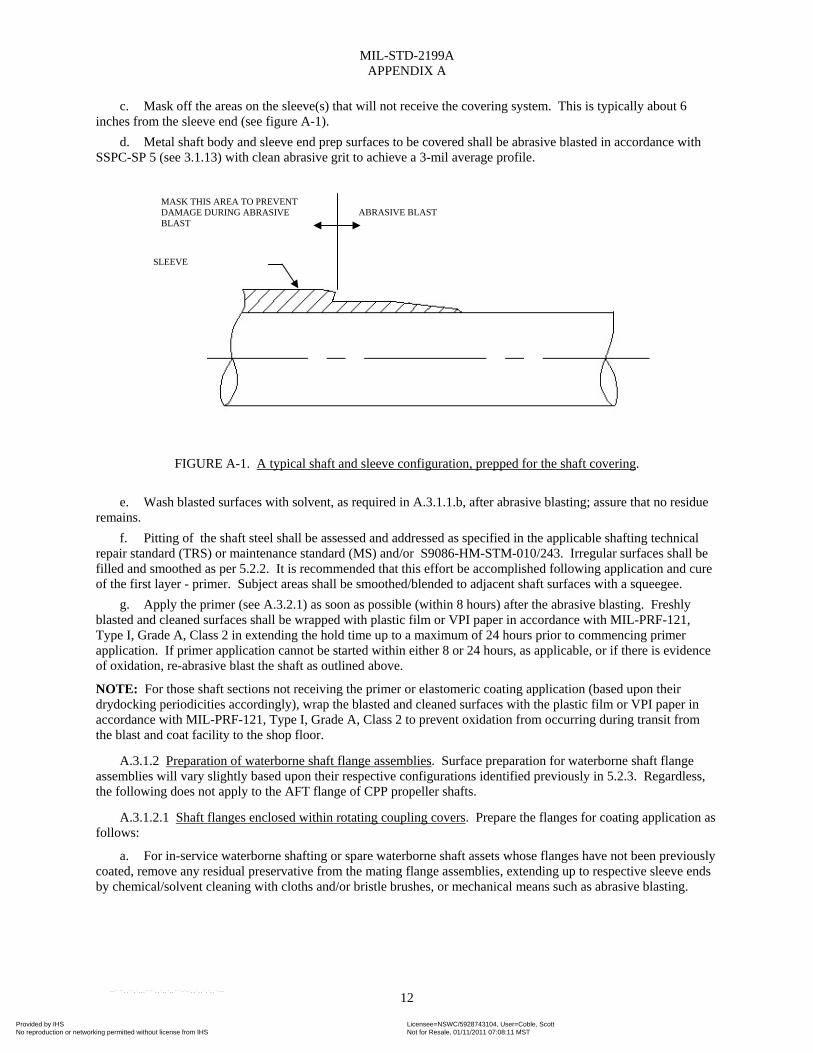
c. Mask off the areas on the sleeve(s) that will not receive the covering system. This is typically about 6 inches from the sleeve end (see figure A-1).
d. Metal shaft body and sleeve end prep surfaces to be covered shall be abrasive blasted in accordance with SSPC-SP 5 (see 3.1.13) with clean abrasive grit to achieve a 3-mil average profile.
FIGURE A-1. A typical shaft and sleeve configuration, prepped for the shaft covering.
e. Wash blasted surfaces with solvent, as required in A.3.1.1.b, after abrasive blasting; assure that no residue
remains.
f. Pitting of the shaft steel shall be assessed and addressed as specified in the applicable shafting technical repair standard (TRS) or maintenance standard (MS) and/or S9086-HM-STM-010/243. Irregular surfaces shall be filled and smoothed as per 5.2.2. It is recommended that this effort be accomplished following application and cure of the first layer - primer. Subject areas shall be smoothed/blended to adjacent shaft surfaces with a squeegee.
g. Apply the primer (see A.3.2.1) as soon as possible (within 8 hours) after the abrasive blasting. Freshly blasted and cleaned surfaces shall be wrapped with plastic film or VPI paper in accordance with MIL-PRF-121, Type I, Grade A, Class 2 in extending the hold time up to a maximum of 24 hours prior to commencing primer application. If primer application cannot be started within either 8 or 24 hours, as applicable, or if there is evidence of oxidation, re-abrasive blast the shaft as outlined above.
NOTE: For those shaft sections not receiving the primer or elastomeric coating application (based upon their drydocking periodicities accordingly), wrap the blasted and cleaned surfaces with the plastic film or VPI paper in accordance with MIL-PRF-121, Type I, Grade A, Class 2 to prevent oxidation from occurring during transit from the blast and coat facility to the shop floor.
A.3.1.2 Preparation of waterborne shaft flange assemblies. Surface preparation for waterborne shaft flange assemblies will vary slightly based upon their respective configurations identified previously in 5.2.3. Regardless, the following does not apply to the AFT flange of CPP propeller shafts.
A.3.1.2.1 Shaft flanges enclosed within rotating coupling covers. Prepare the flanges for coating application as follows:
a. For in-service waterborne shafting or spare waterborne shaft assets whose flanges have not been previously coated, remove any residual preservative from the mating flange assemblies, extending up to respective sleeve ends by chemical/solvent cleaning with cloths and/or bristle brushes, or mechanical means such as abrasive blasting.
ABRASIVE BLASTMASK THIS AREA TO PREVENT DAMAGE DURING ABRASIVE BLAST
SLEEVE
Provided by IHS Licensee=NSWC/5928743104, User=Coble, ScottNot for Resale, 01/11/2011 07:08:11 MSTNo reproduction or networking permitted without license from IHS
--````,,``,`,,,````,,`,,`,,```-`-`,,`,,`,`,,`---

MIL-STD-2199A APPENDIX A
13
b. Remove any oil or grease from the flange surfaces by solvent cleaning (using petroleum distillate type solvent in accordance with MIL-PRF-680, Type II or other solvent that provides suitable cleaning and degreasing capability without leaving a residue) in accordance with SSPC-SP 1 (see 3.1.12). Solvents shall not be ozone depleting types and shall be acceptable under local, State and Federal regulations, as required.
c. Mask off the coupling cover sleeve(s) as well as the flange bolt holes, bolt head/nut washer faces, and mating flange faces.
d. Abrasive blast the exposed metal flange surfaces to SSPC-SP 5 (see 3.1.13).
e. Upon completion of abrasive blasting, solvent clean the blasted flange surfaces in accordance with step b above.
f. Begin flange preservation (see A.3.3.1) as soon as possible (within 8 hours) after the abrasive blasting. Freshly blasted and cleaned surfaces shall be wrapped with plastic film or VPI paper in accordance with MIL-PRF-121, Type I, Grade A, Class 2 in extending the hold time up to a maximum of 24 hours prior to commencing coating application. If primer application cannot be started within either 8 or 24 hours, as applicable, or if there is evidence of oxidation, re-abrasive blast the flange as outlined above.
A.3.1.2.2 Coated flanges normally exposed to seawater. Prepare the flanges for coating application as follows:
a. Remove all pre-existing covering, including GRP and epoxy, by mechanical means. A disc sander, Dremel tool (or equal), or suitable abrasive cutting tool may be used to score the GRP. The GRP is to then be removed with a disc sander after being scored. Remove the epoxy utilizing a disc sander, flapper wheel, and/or wire brush.
NOTE: Water/abrasive blasting is also an acceptable method to remove any pre-existing covering. Regardless of the process utilized, exercise extreme caution not to damage the underlying shaft surface.
b. Remove any oil or grease from the flange surfaces by solvent cleaning (using petroleum distillate type solvent in accordance with MIL-PRF-680, Type II or other solvent that provides suitable cleaning and degreasing capability without leaving a residue) in accordance with NACE SSPC-SP 1 (see 3.1.12). Solvents shall not be ozone depleting types and shall be acceptable under local, State and Federal regulations, as required.
c. Mask off the flange bolt holes, bolt head/nut washer faces, and mating flange faces. If the shaft is configured with independent fairwater sleeve(s), mask-off the sleeve(s) as shown on figure A-1.
d. Abrasive blast the exposed metal flange surfaces and fairwater sleeve end prep area(s), as applicable, to NACE SSPC-SP 5 (see 3.1.13).
e. Upon completion of abrasive blasting, solvent clean the blasted surfaces in accordance with step b above.
f. Begin flange preservation (see A.3.3.2) as soon as possible (within 8 hours) after the abrasive blasting. Freshly blasted and cleaned surfaces shall be wrapped with plastic film or VPI paper in accordance with MIL-PRF-121, Type I, Grade A, Class 2 in extending the hold time up to a maximum of 24 hours prior to commencing coating application. If primer application cannot be started within either 8 or 24 hours, as applicable, or if there is evidence of oxidation, re-abrasive blast the flange as outlined above.
A.3.1.3 Preparation of the shaft-to-sleeve end interfaces.
A.3.1.3.1 Preserving the sleeve end prep area. Experience has shown that application of the shaft covering is most critical in the sleeve end prep area, specifically at the interface of the sleeve end and the shaft. Most historical shaft failures were found to initiate in this area, which is thought to be due to cracks which form in the rigid fairing compound due to shaft torsion. For this reason, an elastomeric coating and polysulfide sealing/fairing compound were selected for application in shaft preservation. Specific focus shall be directed at the sleeve end during all aspects of the shaft coating. Abrasive blast and subsequent primer, coating, and sealant application shall be done with particular care at the shaft-to-sleeve interface.
A.3.1.3.2 Sleeve masking precautions. The four-layer system shaft coating system bridges the shaft and sleeve. It covers the entire shaft body area(s) and extends approximately 5 inches up each interfacing sleeve end. If the materials applied to the shaft sleeve(s) during steps A.3.1.1.c and A.3.1.2.2.c to mask off areas of the sleeve(s) were damaged during blasting, they shall be replaced prior to commencing application of the covering system.
Provided by IHS Licensee=NSWC/5928743104, User=Coble, ScottNot for Resale, 01/11/2011 07:08:11 MSTNo reproduction or networking permitted without license from IHS
--````,,``,`,,,````,,`,,`,,```-`-`,,`,,`,`,,`---
MIL-STD-2199A APPENDIX A
14
A.3.2 Shaft covering system application.
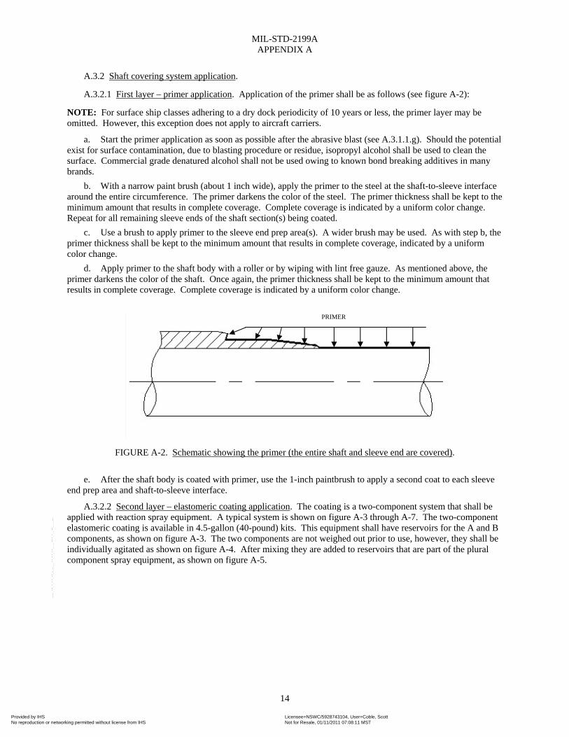
A.3.2.1 First layer – primer application. Application of the primer shall be as follows (see figure A-2):
NOTE: For surface ship classes adhering to a dry dock periodicity of 10 years or less, the primer layer may be omitted. However, this exception does not apply to aircraft carriers.
a. Start the primer application as soon as possible after the abrasive blast (see A.3.1.1.g). Should the potential exist for surface contamination, due to blasting procedure or residue, isopropyl alcohol shall be used to clean the surface. Commercial grade denatured alcohol shall not be used owing to known bond breaking additives in many brands.
b. With a narrow paint brush (about 1 inch wide), apply the primer to the steel at the shaft-to-sleeve interface around the entire circumference. The primer darkens the color of the steel. The primer thickness shall be kept to the minimum amount that results in complete coverage. Complete coverage is indicated by a uniform color change. Repeat for all remaining sleeve ends of the shaft section(s) being coated.
c. Use a brush to apply primer to the sleeve end prep area(s). A wider brush may be used. As with step b, the primer thickness shall be kept to the minimum amount that results in complete coverage, indicated by a uniform color change.
d. Apply primer to the shaft body with a roller or by wiping with lint free gauze. As mentioned above, the primer darkens the color of the shaft. Once again, the primer thickness shall be kept to the minimum amount that results in complete coverage. Complete coverage is indicated by a uniform color change.
FIGURE A-2. Schematic showing the primer (the entire shaft and sleeve end are covered).
e. After the shaft body is coated with primer, use the 1-inch paintbrush to apply a second coat to each sleeve
end prep area and shaft-to-sleeve interface.
A.3.2.2 Second layer – elastomeric coating application. The coating is a two-component system that shall be applied with reaction spray equipment. A typical system is shown on figure A-3 through A-7. The two-component elastomeric coating is available in 4.5-gallon (40-pound) kits. This equipment shall have reservoirs for the A and B components, as shown on figure A-3. The two components are not weighed out prior to use, however, they shall be individually agitated as shown on figure A-4. After mixing they are added to reservoirs that are part of the plural component spray equipment, as shown on figure A-5.
PRIMER
Provided by IHS Licensee=NSWC/5928743104, User=Coble, ScottNot for Resale, 01/11/2011 07:08:11 MSTNo reproduction or networking permitted without license from IHS
--````,,``,`,,,````,,`,,`,,```-`-`,,`,,`,`,,`---
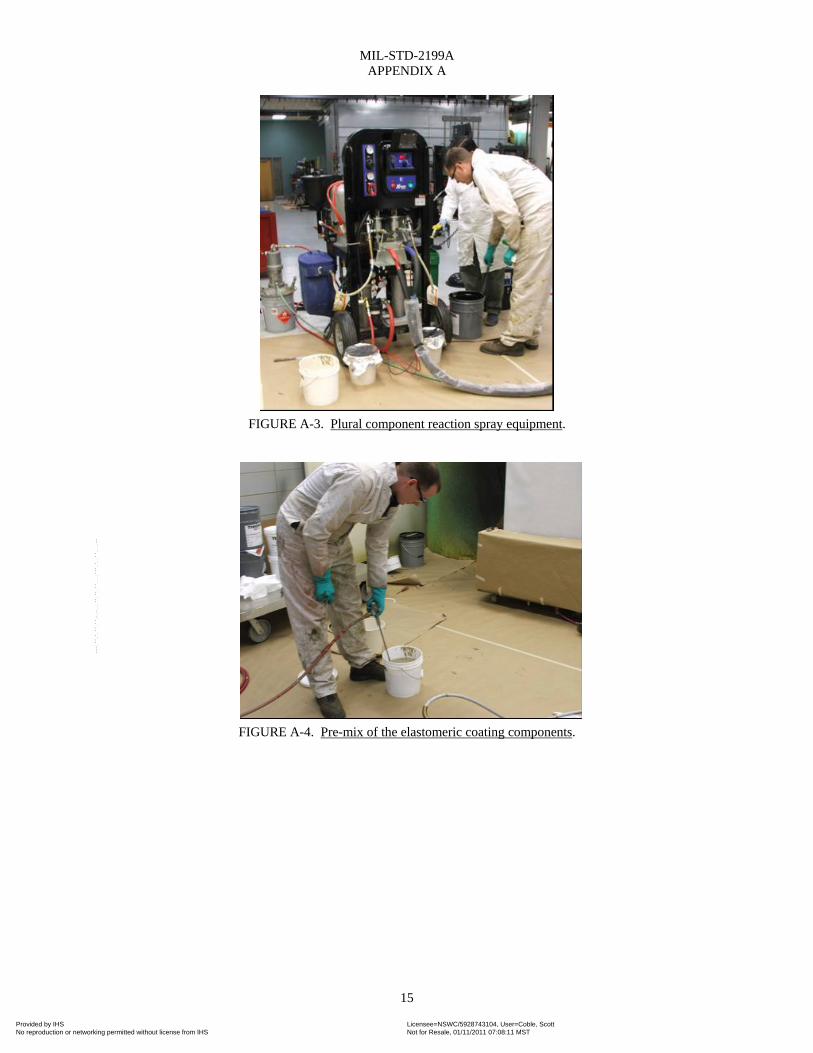
MIL-STD-2199A APPENDIX A
15
FIGURE A-3. Plural component reaction spray equipment.
FIGURE A-4. Pre-mix of the elastomeric coating components.
Provided by IHS Licensee=NSWC/5928743104, User=Coble, ScottNot for Resale, 01/11/2011 07:08:11 MSTNo reproduction or networking permitted without license from IHS
--````,,``,`,,,````,,`,,`,,```-`-`,,`,,`,`,,`---
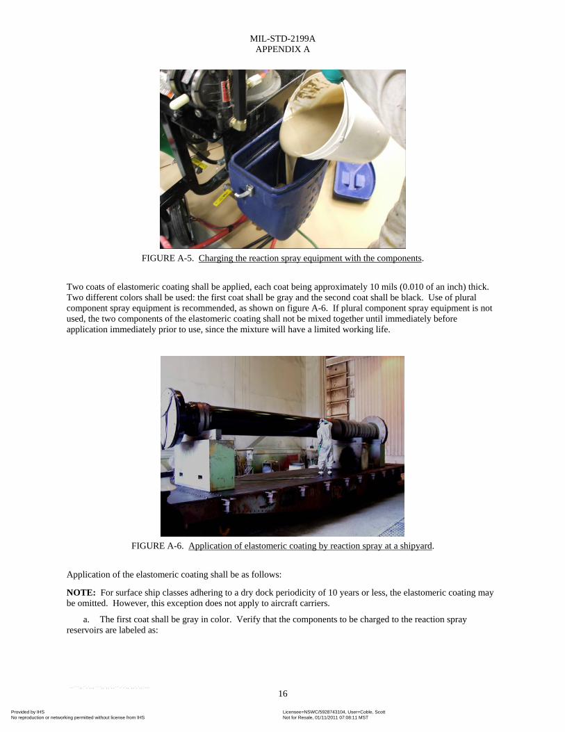
MIL-STD-2199A APPENDIX A
16
FIGURE A-5. Charging the reaction spray equipment with the components.
Two coats of elastomeric coating shall be applied, each coat being approximately 10 mils (0.010 of an inch) thick. Two different colors shall be used: the first coat shall be gray and the second coat shall be black. Use of plural component spray equipment is recommended, as shown on figure A-6. If plural component spray equipment is not used, the two components of the elastomeric coating shall not be mixed together until immediately before application immediately prior to use, since the mixture will have a limited working life.
FIGURE A-6. Application of elastomeric coating by reaction spray at a shipyard.
Application of the elastomeric coating shall be as follows:
NOTE: For surface ship classes adhering to a dry dock periodicity of 10 years or less, the elastomeric coating may be omitted. However, this exception does not apply to aircraft carriers.
a. The first coat shall be gray in color. Verify that the components to be charged to the reaction spray reservoirs are labeled as:
Provided by IHS Licensee=NSWC/5928743104, User=Coble, ScottNot for Resale, 01/11/2011 07:08:11 MSTNo reproduction or networking permitted without license from IHS
--````,,``,`,,,````,,`,,`,,```-`-`,,`,,`,`,,`---
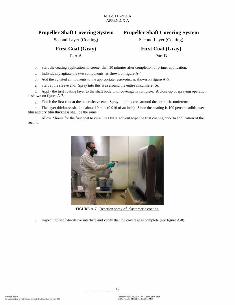
MIL-STD-2199A APPENDIX A
17
Propeller Shaft Covering System Second Layer (Coating)
Propeller Shaft Covering System Second Layer (Coating)
First Coat (Gray) Part A
First Coat (Gray) Part B
b. Start the coating application no sooner than 30 minutes after completion of primer application.
c. Individually agitate the two components, as shown on figure A-4.
d. Add the agitated components to the appropriate reservoirs, as shown on figure A-5.
e. Start at the sleeve end. Spray into this area around the entire circumference.
f. Apply the first coating layer to the shaft body until coverage is complete. A close-up of spraying operation is shown on figure A-7.
g. Finish the first coat at the other sleeve end. Spray into this area around the entire circumference.
h. The layer thickness shall be about 10 mils (0.010 of an inch). Since the coating is 100 percent solids, wet film and dry film thickness shall be the same.
i. Allow 2 hours for the first coat to cure. DO NOT solvent wipe the first coating prior to application of the second.
FIGURE A-7. Reaction spray of elastomeric coating.
j. Inspect the shaft-to-sleeve interface and verify that the coverage is complete (see figure A-8).
Provided by IHS Licensee=NSWC/5928743104, User=Coble, ScottNot for Resale, 01/11/2011 07:08:11 MSTNo reproduction or networking permitted without license from IHS
--````,,``,`,,,````,,`,,`,,```-`-`,,`,,`,`,,`---
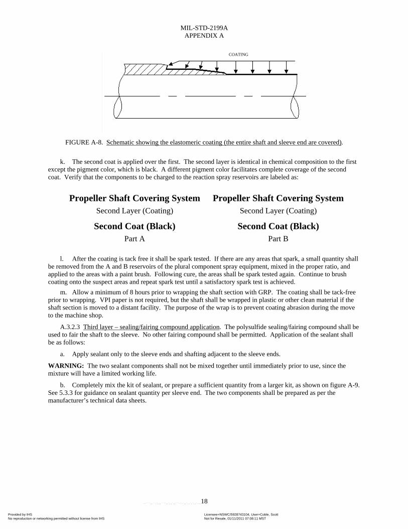
MIL-STD-2199A APPENDIX A
18
FIGURE A-8. Schematic showing the elastomeric coating (the entire shaft and sleeve end are covered).
k. The second coat is applied over the first. The second layer is identical in chemical composition to the first
except the pigment color, which is black. A different pigment color facilitates complete coverage of the second coat. Verify that the components to be charged to the reaction spray reservoirs are labeled as:
Propeller Shaft Covering SystemSecond Layer (Coating)
Propeller Shaft Covering System Second Layer (Coating)
Second Coat (Black) Part A
Second Coat (Black) Part B
l. After the coating is tack free it shall be spark tested. If there are any areas that spark, a small quantity shall
be removed from the A and B reservoirs of the plural component spray equipment, mixed in the proper ratio, and applied to the areas with a paint brush. Following cure, the areas shall be spark tested again. Continue to brush coating onto the suspect areas and repeat spark test until a satisfactory spark test is achieved.
m. Allow a minimum of 8 hours prior to wrapping the shaft section with GRP. The coating shall be tack-free prior to wrapping. VPI paper is not required, but the shaft shall be wrapped in plastic or other clean material if the shaft section is moved to a distant facility. The purpose of the wrap is to prevent coating abrasion during the move to the machine shop.
A.3.2.3 Third layer – sealing/fairing compound application. The polysulfide sealing/fairing compound shall be used to fair the shaft to the sleeve. No other fairing compound shall be permitted. Application of the sealant shall be as follows:
a. Apply sealant only to the sleeve ends and shafting adjacent to the sleeve ends.
WARNING: The two sealant components shall not be mixed together until immediately prior to use, since the mixture will have a limited working life.
b. Completely mix the kit of sealant, or prepare a sufficient quantity from a larger kit, as shown on figure A-9. See 5.3.3 for guidance on sealant quantity per sleeve end. The two components shall be prepared as per the manufacturer’s technical data sheets.
COATING
Provided by IHS Licensee=NSWC/5928743104, User=Coble, ScottNot for Resale, 01/11/2011 07:08:11 MSTNo reproduction or networking permitted without license from IHS
--````,,``,`,,,````,,`,,`,,```-`-`,,`,,`,`,,`---

MIL-STD-2199A APPENDIX A
19
FIGURE A-9. Mixing a kit of sealing/fairing compound.
c. Apply the sealant with a squeegee to the rotating shaft. Coverage shall include the bearing sleeve-end
treatment and about 6 inches of shafting. The sealant shall fair the shaft to the sleeve (see figure A-10).
FIGURE A-10. Schematic showing sealing/fairing compound (only the sleeve end area is covered).
d. Use of a wide (approximately 12-inch) squeegee (or equivalent) is recommended to spread and distribute
the sealant while the shaft rotates, as shown on figures A-11 and A-12. The sleeve end is shown fair with the shaft on figure A-13. The thickness in way of the bearing sleeve and shafting shall be approximately 20 mils (0.020 of an inch), except at the sleeve end. At the sleeve end the thickness of the sealant shall be that necessary to fair the shaft to the sleeve. Thus, the thickness at the sleeve end shall be approximately the thickness of the sleeve at the end plus 20 mils.
SEALING/FAIRING COMPOUND
Provided by IHS Licensee=NSWC/5928743104, User=Coble, ScottNot for Resale, 01/11/2011 07:08:11 MSTNo reproduction or networking permitted without license from IHS
--````,,``,`,,,````,,`,,`,,```-`-`,,`,,`,`,,`---
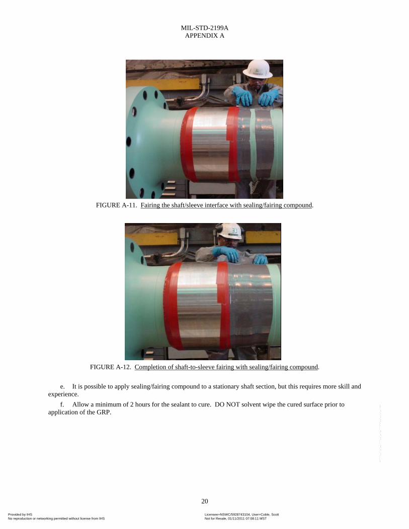
MIL-STD-2199A APPENDIX A
20
FIGURE A-11. Fairing the shaft/sleeve interface with sealing/fairing compound.
FIGURE A-12. Completion of shaft-to-sleeve fairing with sealing/fairing compound.
e. It is possible to apply sealing/fairing compound to a stationary shaft section, but this requires more skill and
experience.
f. Allow a minimum of 2 hours for the sealant to cure. DO NOT solvent wipe the cured surface prior to application of the GRP.
Provided by IHS Licensee=NSWC/5928743104, User=Coble, ScottNot for Resale, 01/11/2011 07:08:11 MSTNo reproduction or networking permitted without license from IHS
--````,,``,`,,,````,,`,,`,,```-`-`,,`,,`,`,,`---

MIL-STD-2199A APPENDIX A
21
FIGURE A-13. View of gray sealing/fairing compound applied over second layer of elastomeric coating (black).
A.3.2.4 Fourth layer – GRP application. Application of the fiberglass tape and resin on the shaft body area(s) shall be as follows:
NOTE: Provisions for application of GRP on waterborne propulsion shafting for Navy ships and submarines are identified in 803-2145807. Extreme care shall be taken to keep the glass tape free of dirt, dust and other contaminants. Tape that has been exposed to water, solvents and lubricants is not useable and shall be discarded.
a. Review and observe the safety precautions (see 5.4).
b. Prepare the required quantities of materials (see 5.3.4).
c. Pour or brush mixed resin on top of the shaft as it rotates. It should be noted that the preferred method of application of the covering is to a rotating shaft. Resin drainage is usually not a problem and overall quality is better. Recommended speed of the shaft rotation in revolutions per minute (r/min) shall be determined as follows: when shaft diameter (d) is in inches, 180 divided by d equals r/min. For example, for a 10-inch diameter shaft, the recommended rotational speed would be:
180/10 = 18 r/min
Spread the resin with gloved hands, brush, or roller to completely wet-out the shaft and sleeve surfaces and to provide a resin base to impregnate the first ply of the tape to be applied.
d. To start the wrap, wind one complete circumferential turn of tape around the shaft to completely cover the tape end. Then gradually, in two or three turns, decrease the tape overlap and work into a spiral with edges of the tape continuously butted as closely as possible to avoid gaps in coverage. On rotating shafts, two people are generally required to handle a roll of tape; one holds and feeds the tape from the roll to the second person who guides the tape onto the rotating resin coated shaft. Although the preferred method of application is to a rotating shaft, GRP can be applied to a stationary shaft. On a stationary shaft, this operation shall be accomplished with two people, one on each side of the shaft, who pass the roll of tape to each other over and under the shaft. The tape shall be carefully butted and applied with some tension so that the wrap is fairly tight, but not so tight as to pucker or distort the tape. Apply additional resin to the surface, if needed, to completely impregnate the tape. An effort shall be made to apply enough resin initially to impregnate the tape without the need to apply additional resin on top of the tape. The glass tape shall be coated uniformly and thoroughly so that good wetting of the glass fibers is obtained. After allowing time for wetting by the resin, work out entrapped air with a roller, squeegee, or other convenient method.
e. If there is a flange, start or end each ply of tape by butting as close to the flange as possible. To provide complete shaft coverage, the tape, which is spiral wound around the shaft, shall end up normal (90 degrees) to the shaft axis at both ends of the coated length. Several tape widths from the end, begin reducing the spiral angle to achieve an increasing overlap, minimize wrinkles, and end with a circumferential turn.
Provided by IHS Licensee=NSWC/5928743104, User=Coble, ScottNot for Resale, 01/11/2011 07:08:11 MSTNo reproduction or networking permitted without license from IHS
--````,,``,`,,,````,,`,,`,,```-`-`,,`,,`,`,,`---
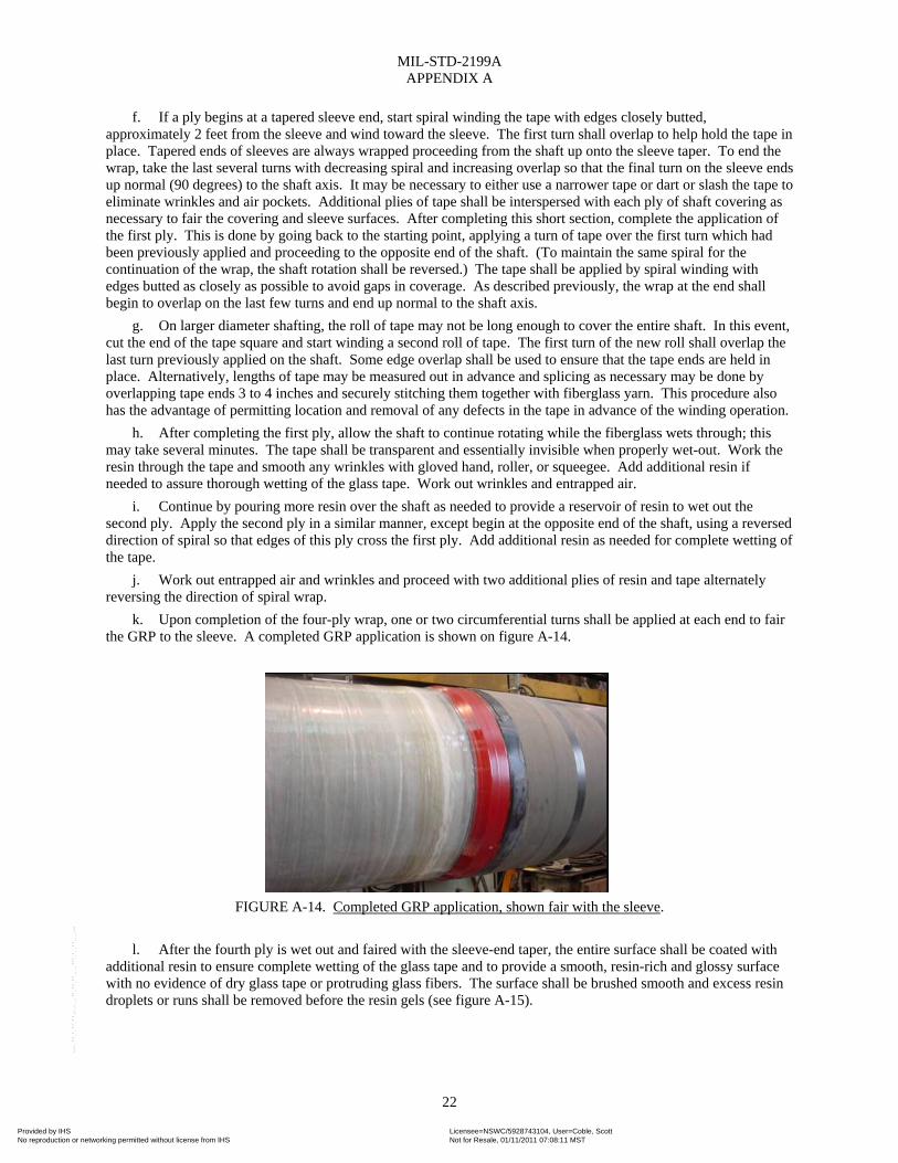
MIL-STD-2199A APPENDIX A
22
f. If a ply begins at a tapered sleeve end, start spiral winding the tape with edges closely butted, approximately 2 feet from the sleeve and wind toward the sleeve. The first turn shall overlap to help hold the tape in place. Tapered ends of sleeves are always wrapped proceeding from the shaft up onto the sleeve taper. To end the wrap, take the last several turns with decreasing spiral and increasing overlap so that the final turn on the sleeve ends up normal (90 degrees) to the shaft axis. It may be necessary to either use a narrower tape or dart or slash the tape to eliminate wrinkles and air pockets. Additional plies of tape shall be interspersed with each ply of shaft covering as necessary to fair the covering and sleeve surfaces. After completing this short section, complete the application of the first ply. This is done by going back to the starting point, applying a turn of tape over the first turn which had been previously applied and proceeding to the opposite end of the shaft. (To maintain the same spiral for the continuation of the wrap, the shaft rotation shall be reversed.) The tape shall be applied by spiral winding with edges butted as closely as possible to avoid gaps in coverage. As described previously, the wrap at the end shall begin to overlap on the last few turns and end up normal to the shaft axis.
g. On larger diameter shafting, the roll of tape may not be long enough to cover the entire shaft. In this event, cut the end of the tape square and start winding a second roll of tape. The first turn of the new roll shall overlap the last turn previously applied on the shaft. Some edge overlap shall be used to ensure that the tape ends are held in place. Alternatively, lengths of tape may be measured out in advance and splicing as necessary may be done by overlapping tape ends 3 to 4 inches and securely stitching them together with fiberglass yarn. This procedure also has the advantage of permitting location and removal of any defects in the tape in advance of the winding operation.
h. After completing the first ply, allow the shaft to continue rotating while the fiberglass wets through; this may take several minutes. The tape shall be transparent and essentially invisible when properly wet-out. Work the resin through the tape and smooth any wrinkles with gloved hand, roller, or squeegee. Add additional resin if needed to assure thorough wetting of the glass tape. Work out wrinkles and entrapped air.
i. Continue by pouring more resin over the shaft as needed to provide a reservoir of resin to wet out the second ply. Apply the second ply in a similar manner, except begin at the opposite end of the shaft, using a reversed direction of spiral so that edges of this ply cross the first ply. Add additional resin as needed for complete wetting of the tape.
j. Work out entrapped air and wrinkles and proceed with two additional plies of resin and tape alternately reversing the direction of spiral wrap.
k. Upon completion of the four-ply wrap, one or two circumferential turns shall be applied at each end to fair the GRP to the sleeve. A completed GRP application is shown on figure A-14.
FIGURE A-14. Completed GRP application, shown fair with the sleeve.
l. After the fourth ply is wet out and faired with the sleeve-end taper, the entire surface shall be coated with
additional resin to ensure complete wetting of the glass tape and to provide a smooth, resin-rich and glossy surface with no evidence of dry glass tape or protruding glass fibers. The surface shall be brushed smooth and excess resin droplets or runs shall be removed before the resin gels (see figure A-15).
Provided by IHS Licensee=NSWC/5928743104, User=Coble, ScottNot for Resale, 01/11/2011 07:08:11 MSTNo reproduction or networking permitted without license from IHS
--````,,``,`,,,````,,`,,`,,```-`-`,,`,,`,`,,`---
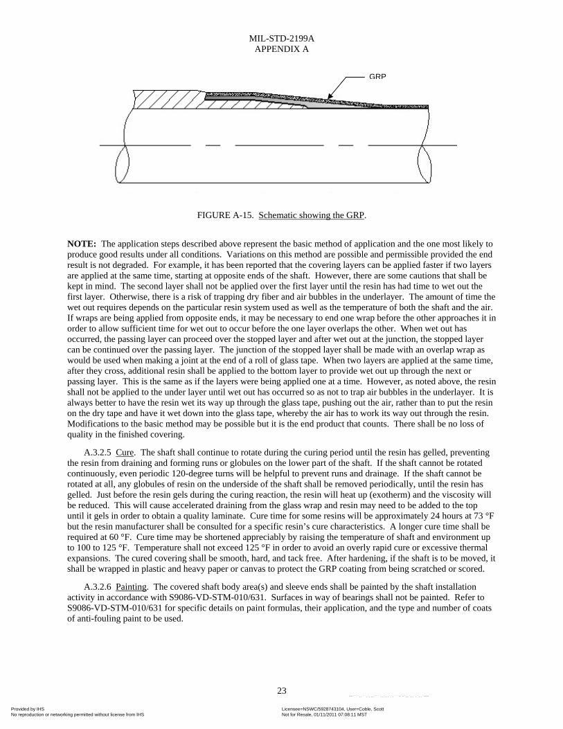
MIL-STD-2199A APPENDIX A
23
FIGURE A-15. Schematic showing the GRP.
NOTE: The application steps described above represent the basic method of application and the one most likely to produce good results under all conditions. Variations on this method are possible and permissible provided the end result is not degraded. For example, it has been reported that the covering layers can be applied faster if two layers are applied at the same time, starting at opposite ends of the shaft. However, there are some cautions that shall be kept in mind. The second layer shall not be applied over the first layer until the resin has had time to wet out the first layer. Otherwise, there is a risk of trapping dry fiber and air bubbles in the underlayer. The amount of time the wet out requires depends on the particular resin system used as well as the temperature of both the shaft and the air. If wraps are being applied from opposite ends, it may be necessary to end one wrap before the other approaches it in order to allow sufficient time for wet out to occur before the one layer overlaps the other. When wet out has occurred, the passing layer can proceed over the stopped layer and after wet out at the junction, the stopped layer can be continued over the passing layer. The junction of the stopped layer shall be made with an overlap wrap as would be used when making a joint at the end of a roll of glass tape. When two layers are applied at the same time, after they cross, additional resin shall be applied to the bottom layer to provide wet out up through the next or passing layer. This is the same as if the layers were being applied one at a time. However, as noted above, the resin shall not be applied to the under layer until wet out has occurred so as not to trap air bubbles in the underlayer. It is always better to have the resin wet its way up through the glass tape, pushing out the air, rather than to put the resin on the dry tape and have it wet down into the glass tape, whereby the air has to work its way out through the resin. Modifications to the basic method may be possible but it is the end product that counts. There shall be no loss of quality in the finished covering.
A.3.2.5 Cure. The shaft shall continue to rotate during the curing period until the resin has gelled, preventing the resin from draining and forming runs or globules on the lower part of the shaft. If the shaft cannot be rotated continuously, even periodic 120-degree turns will be helpful to prevent runs and drainage. If the shaft cannot be rotated at all, any globules of resin on the underside of the shaft shall be removed periodically, until the resin has gelled. Just before the resin gels during the curing reaction, the resin will heat up (exotherm) and the viscosity will be reduced. This will cause accelerated draining from the glass wrap and resin may need to be added to the top until it gels in order to obtain a quality laminate. Cure time for some resins will be approximately 24 hours at 73 °F but the resin manufacturer shall be consulted for a specific resin’s cure characteristics. A longer cure time shall be required at 60 °F. Cure time may be shortened appreciably by raising the temperature of shaft and environment up to 100 to 125 °F. Temperature shall not exceed 125 °F in order to avoid an overly rapid cure or excessive thermal expansions. The cured covering shall be smooth, hard, and tack free. After hardening, if the shaft is to be moved, it shall be wrapped in plastic and heavy paper or canvas to protect the GRP coating from being scratched or scored.
A.3.2.6 Painting. The covered shaft body area(s) and sleeve ends shall be painted by the shaft installation activity in accordance with S9086-VD-STM-010/631. Surfaces in way of bearings shall not be painted. Refer to S9086-VD-STM-010/631 for specific details on paint formulas, their application, and the type and number of coats of anti-fouling paint to be used.
GRP
Provided by IHS Licensee=NSWC/5928743104, User=Coble, ScottNot for Resale, 01/11/2011 07:08:11 MSTNo reproduction or networking permitted without license from IHS
--````,,``,`,,,````,,`,,`,,```-`-`,,`,,`,`,,`---

MIL-STD-2199A APPENDIX A
24
A.3.3 Flange preservation. Waterborne shaft flanges shall be preserved (coated) as follows:
A.3.3.1 Shaft flanges enclosed within rotating coupling covers.
a. Commence flange preservation as soon as possible after the abrasive blast (see A.3.1.2.1.f).
b. Accomplish steps A.3.2.2.a and A.3.2.2.c through A.3.2.2.l, but in reference to the flange surfaces.
NOTE: Documentation already exists on CG 47 and DDG 51 ship classes to apply a Euronavy paint system to the waterborne shaft flanges in way of rotating coupling covers (AER’s 68152 and 66076 apply, respectively). This documentation and associated Euronavy paint system may continue to be used in lieu of the polysulfide elastomeric coating specified above but only for the applicable ship classes outlined therein.
c. Once the coating is tack-free, remove the masking from the sleeves, flange mating faces, bolt holes, and bolt head/nut washer faces.
d. Apply a generous bead of sealing/fairing compound (see A.3.2.3) to the shaft-to-sleeve interfaces. Smooth/blend/fair the sealant with adjacent surfaces.
NOTE: Once the shafts are installed on the ship, the flanges mated, and the coupling bolts installed and torqued, but prior to installation of the rotating coupling cover(s), the elastomeric coating (see A.3.2.2) shall be applied to the bolt heads and nuts as well as respective washer faces. This can be done by taking a small quantity of Parts A and B of the coating, mixing them in the proper ratio, and applying to the areas with a paint brush. The elastomeric coating shall also be applied around the entire circumferential mating joint of the flanges. After the coating is tack free it shall be spark tested. If there are any areas that spark, brush additional coating onto suspect areas. Following cure, the areas shall be spark tested again. Repeat as necessary until a satisfactory spark test is achieved.
A.3.3.2 Shaft flanges normally exposed to seawater.
a. Commence flange preservation as soon as possible after the abrasive blast (see A.3.1.2.2.f).
b. Accomplish steps A.3.2.2.a and A.3.2.2.c through A.3.2.2.l, but in reference to the flange and sleeve end prep surfaces, as applicable.
c. If the shaft is configured with independent fairwater sleeve(s), apply sealing/fairing compound to fair the sleeve end(s) to the shaft in accordance with A.3.2.3.
d. If the shaft is configured with independent fairwater sleeve(s), apply GRP in accordance with A.3.2.4, beginning at the sleeve, over the end prep area, continuing along the straight section of the shaft, and extending as far up the flange fillet as possible.
e. For the remaining flange surfaces that cannot be properly covered with glass tape, one of the following two corrosion protection layers shall be applied:
(1) Two (2) coats of epoxy conforming to MIL-PRF-23236, Class 2. A minimum dry film thickness of 15 mils (0.015 of an inch) shall be achieved.
(2) A resin formulation containing 10 percent by mass of milled glass fibers after the straight run covering has been applied. Any resin remaining from step d above may be used or new batches of resin may be prepared. If new batches are prepared, 10 percent milled glass fibers shall first be added to the resin followed by addition of the curing system (accelerator and catalyst for polyesters and hardener for epoxies). A thixotropic filler (see 5.2.1) may also be added to limit resin drainage (up to 4 percent by mass depending on temperature). Four (4) coats of resin may be sufficient but the total thickness shall not exceed 60 mils (0.060 of an inch). Separate batches of resin shall be prepared for each coat since gelation (partial hardening) may occur before the next coat is applied. In coating the flange surfaces, care shall be exercised with regard to areas around and between bolts in order to avoid holidays or porosity.
NOTE: Regardless of which system outlined above is applied, ensure the masking in way of the bolt head/nut washer faces is removed before the first coat of either system has cured. For each additional coat, exercise extreme caution not to get any paint/resin on the washer faces.
f. Once the coating has cured, remove the remaining masking from the flange mating faces and bolt holes as well as the end(s) of the fairwater sleeve(s), if configured accordingly.
Provided by IHS Licensee=NSWC/5928743104, User=Coble, ScottNot for Resale, 01/11/2011 07:08:11 MSTNo reproduction or networking permitted without license from IHS
--````,,``,`,,,````,,`,,`,,```-`-`,,`,,`,`,,`---

MIL-STD-2199A APPENDIX A
25
NOTE: Once the shafts are installed on the ship, the flanges mated, and the coupling bolts installed and torqued, the elastomeric coating (see A.3.2.2) along with whichever corrosion protection layer was applied in step e above shall also be applied to the bolt heads and nuts as well as respective washer faces. The coating and protective layer shall also be applied around the entire circumferential mating joint of the flanges. This can be done by taking a small quantity of Parts A and B of the coating, mixing them in the proper ratio, and applying to the areas with a paint brush. After the coating is tack free it shall be spark tested. If there are any areas that spark, brush additional coating onto suspect areas. Following cure, the areas shall be spark tested again. Repeat as necessary until a satisfactory spark test is achieved. Then, apply the same protective layer to subject surfaces as done previously for the other flange areas.
Provided by IHS Licensee=NSWC/5928743104, User=Coble, ScottNot for Resale, 01/11/2011 07:08:11 MSTNo reproduction or networking permitted without license from IHS
--````,,``,`,,,````,,`,,`,,```-`-`,,`,,`,`,,`---
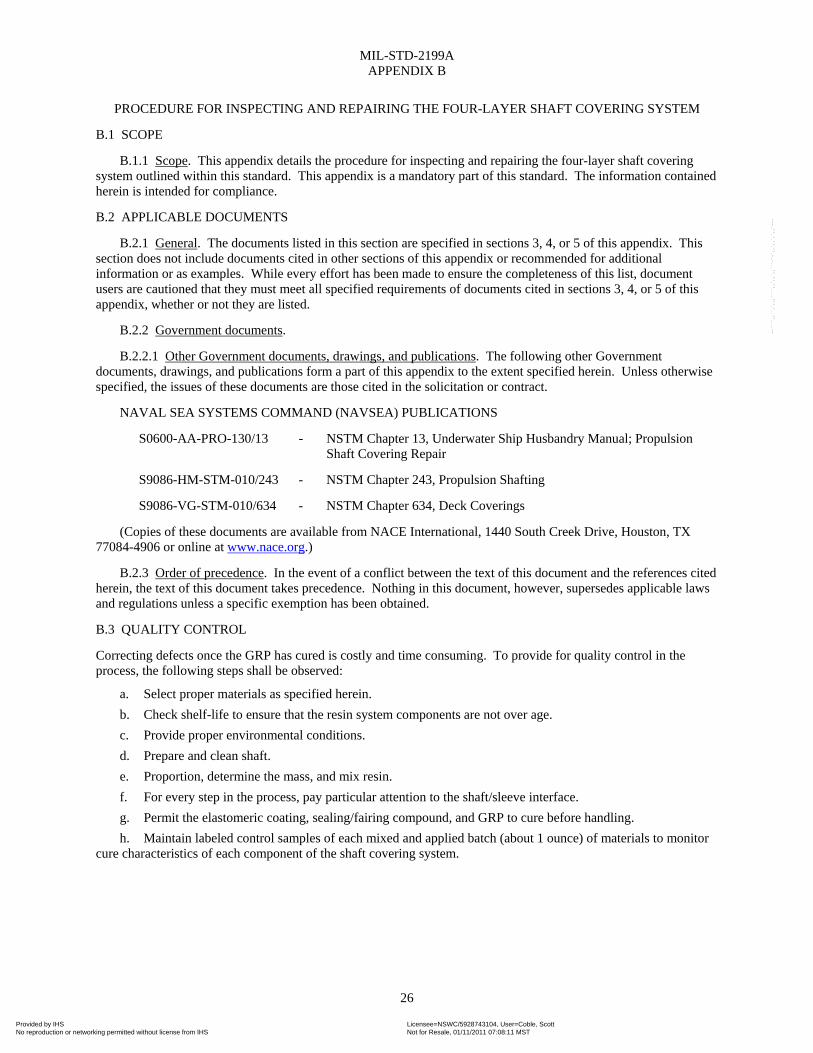
MIL-STD-2199A APPENDIX B
26
PROCEDURE FOR INSPECTING AND REPAIRING THE FOUR-LAYER SHAFT COVERING SYSTEM
B.1 SCOPE
B.1.1 Scope. This appendix details the procedure for inspecting and repairing the four-layer shaft covering system outlined within this standard. This appendix is a mandatory part of this standard. The information contained herein is intended for compliance.
B.2 APPLICABLE DOCUMENTS
B.2.1 General. The documents listed in this section are specified in sections 3, 4, or 5 of this appendix. This section does not include documents cited in other sections of this appendix or recommended for additional information or as examples. While every effort has been made to ensure the completeness of this list, document users are cautioned that they must meet all specified requirements of documents cited in sections 3, 4, or 5 of this appendix, whether or not they are listed.
B.2.2 Government documents.
B.2.2.1 Other Government documents, drawings, and publications. The following other Government documents, drawings, and publications form a part of this appendix to the extent specified herein. Unless otherwise specified, the issues of these documents are those cited in the solicitation or contract.
NAVAL SEA SYSTEMS COMMAND (NAVSEA) PUBLICATIONS
S0600-AA-PRO-130/13 - NSTM Chapter 13, Underwater Ship Husbandry Manual; Propulsion Shaft Covering Repair
S9086-HM-STM-010/243 - NSTM Chapter 243, Propulsion Shafting
S9086-VG-STM-010/634 - NSTM Chapter 634, Deck Coverings
(Copies of these documents are available from NACE International, 1440 South Creek Drive, Houston, TX 77084-4906 or online at www.nace.org.)
B.2.3 Order of precedence. In the event of a conflict between the text of this document and the references cited herein, the text of this document takes precedence. Nothing in this document, however, supersedes applicable laws and regulations unless a specific exemption has been obtained.
B.3 QUALITY CONTROL
Correcting defects once the GRP has cured is costly and time consuming. To provide for quality control in the process, the following steps shall be observed:
a. Select proper materials as specified herein.
b. Check shelf-life to ensure that the resin system components are not over age.
c. Provide proper environmental conditions.
d. Prepare and clean shaft.
e. Proportion, determine the mass, and mix resin.
f. For every step in the process, pay particular attention to the shaft/sleeve interface.
g. Permit the elastomeric coating, sealing/fairing compound, and GRP to cure before handling.
h. Maintain labeled control samples of each mixed and applied batch (about 1 ounce) of materials to monitor cure characteristics of each component of the shaft covering system.
Provided by IHS Licensee=NSWC/5928743104, User=Coble, ScottNot for Resale, 01/11/2011 07:08:11 MSTNo reproduction or networking permitted without license from IHS
--````,,``,`,,,````,,`,,`,,```-`-`,,`,,`,`,,`---
MIL-STD-2199A APPENDIX B
27
B.3.1 Shaft covering inspections. The shaft covering shall be inspected after application (before painting), at each drydocking, and during routine underwater hull inspections.
NOTE: If the shaft covering is so severely damaged as to preclude repair, the entire covering shall be removed and the shafting re-covered as a new installation by the procedures described herein. The covering is to be removed by machining using a blunted (bull nose) machine tool. Exercise extreme caution so as not to damage the underlying shaft surface when removing the GRP.
B.3.1.1 Post application inspection and repair. The following inspections shall be conducted after the GRP has hardened. Corresponding corrective actions shall also be accomplished pending results of the inspection.
B.3.1.1.1 Inspection.
a. Visually inspect the GRP, paying particular attention to the GRP-to-sleeve interfaces and those flanges coated with a resin formulation. Look for discoloration which may be evidence of overheating during cure, white laminate which indicates poor wet-out, air bubbles, pimples, or rough spots.
b. Tap suspicious looking areas with a coin. A dull or hollow sound indicates trapped air or de-bonded area.
c. Slowly pass a high voltage spark tester over the entire coated area, with particular attention paid to the suspicious areas. Pinholes are evidenced by bright sparks, which can be clearly distinguished from the purplish corona. (A suitable spark tester is shown in S9086-VG-STM-010/634.)
B.3.1.1.2 Corrective action.
a. Surface defects, such as areas containing isolated or scattered pinholes, pimples, or rough spots, shall be sanded smooth and recoated with resin used for the shaft covering.
b. Widespread area(s) of air bubbles or pinholes shall be repaired by sanding the GRP surface completely around the circumference and applying an additional ply of tape and resin to cover the defective area.
NOTE: Air bubbles or pinholes identified on flanges coated with a resin formulation shall be repaired by removing the resin in way of the defective area(s) and having the resin formulation re-applied (see A.2.3.2.e.2).
c. Area(s) which appear to be debonded or area(s) of white laminate shall be repaired as follows:
(1) Remove the fiberglass tape and resin, around the entire circumference of the shaft in way of each defective area, until fully bonded GRP is reached. A disc sander, Dremel tool (or equal), or suitable abrasive cutting tool may be used to score the GRP. The fiberglass cover in the damaged or defective area is to be removed with a disc sander after being scored. Exercise extreme caution not to damage the underlying shaft surface when removing the GRP.
NOTE: For those shaft sections to which the elastomeric coating was applied, make every attempt to remove the GRP only down to the coating layer. The GRP should be able to be peeled/torn away from the polysulfide coating, leaving the coating intact to the maximum extent possible.
(2) Bevel the edges of the GRP on both sides of each defective area 1 to 2 inches.
(3) For those shaft sections to which the elastomeric coating was applied, apply an additional layer of the coating (Second Coat – Black) over the entire shaft area(s) from which the GRP was removed (see A.3.2.2). Blend the coating layer onto the beveled edges of the GRP.
NOTE: A small quantity of Parts A and B can be mixed in the proper ratio and applied to the area(s) with a paint brush.
(4) Once the elastomeric coating is tack-free, it shall be spark tested. If there are any areas that spark, continue to brush coating onto the suspect areas and repeat spark test until a satisfactory spark test is achieved.
(5) Prepare a length of glass tape sufficient to provide a four-ply covering for each band to be repaired; for narrow repair sections, use 2- to 4-inch wide glass tape. Re-apply GRP over the area(s) from which it was removed in accordance with A.3.2.4. Ensure the GRP extends over the beveled edges and smoothly blends with adjacent GRP surfaces.
d. After cure, re-inspect each of the repaired areas with the spark tester and repeat respective applications as required until a satisfactory spark test is achieved.
Provided by IHS Licensee=NSWC/5928743104, User=Coble, ScottNot for Resale, 01/11/2011 07:08:11 MSTNo reproduction or networking permitted without license from IHS
--````,,``,`,,,````,,`,,`,,```-`-`,,`,,`,`,,`---

MIL-STD-2199A APPENDIX B
28
e. Paint each repaired area in accordance with A.3.2.6.
B.3.1.2 Dry-dock inspection and repair. Waterborne main propulsion shaft coverings shall be inspected to the maximum extent possible every time a ship comes into drydock. Shaft coverings that have been in-service shall be inspected and repaired as follows:
B.3.1.2.1 Inspection.
a. Remove marine growth and/or loose paint from the GRP, including couplings and other areas, by scraping carefully, so as not to score or damage the GRP.
NOTE: The GRP may also be lightly sanded if hand scraping is unsuccessful. Abrasive blasting is also permitted, although not recommended, since it could potentially damage the covering, shattering the glass fibers. However, if abrasive blasting is utilized, fine or medium grit shall be used along with mild blasting conditions (for example, low air pressure, low-grit velocity).
b. Conduct, at close range, a careful visual inspection of the full length of all accessible/exposed GRP for evidence of deterioration, physical damage, lack of adhesion, and/or any other defects. Particular attention is to be paid to the GRP-to-shaft sleeve interfaces for indication of seawater penetration, as evidenced by rust color staining bleeding through at subject interfaces. If damaged or suspect conditions are found, mark all areas with chalk (do not use crayon or “grease” pencil as they have paraffin and waxes in their makeup).
NOTE: Evidence of loss of adhesion of shaft covering is typically characterized by one or more of the following:
(1) Loss of GRP as a whole or in part.
(2) Rust stains where rust has leaked through the covering in the vicinity of a cut, joint, patch, or flaws, such as pinholes or porosity.
c. Tap the GRP at regular intervals of about 18 inches along the length of the covering with a light hammer rap while holding the palm of one hand against the GRP adjacent to the area being tapped. Discernible vibration, movement of the GRP, or an audible hollow sound is evidence of a loose bond and shall be examined further. If suspect area(s) are found, mark with chalk accordingly (do not use crayon or “grease” pencil as they have paraffin and waxes in their makeup).
d. Carefully inspect the entire GRP for damage/porosity with a high frequency spark tester. Particular attention shall be given to the sleeve-to-GRP interfaces. If there are any areas that spark, mark with chalk accordingly (do not use crayon or “grease” pencil as they have paraffin and waxes in their makeup).
B.3.1.2.2 Repair (for shafts possessing the four-layer covering system).
B.3.1.2.2.1 Repair of visible surface defects. If the GRP contains visible surface defects such as scattered or isolated pinholes, pimples, porosity, or rough spots, none of which produced a spark during the spark test, coat subject areas with resin as follows:
NOTE: Use a 5× (minimum) magnifying glass to verify the presence of any suspected defects.
a. Sand the GRP lightly or abrasive blast lightly in way of the defective area. If the GRP had been treated with anti-fouling paint, abrasive blasting may be necessary to remove the paint. When abrasive blasting, precautions shall be taken to avoid damage to the GRP by abrasion deeper than just surface roughening. Use fine or medium grit and mild conditions (for example, low air pressure, low grit velocity). Do not dwell at one spot excessively. Careless or indiscriminate abrasive blasting will damage the GRP severely.
b. Clean away all sanding or abrasive blasting grit or residue and apply one coat of resin over the affected surface(s).
c. After the resin has hardened, re-examine the repaired area(s) with a 5× (minimum) magnifying glass for any evidence of remaining defects. Repeat application of the resin and re-inspect, as required, until there are no apparent defects remaining.
d. Paint each repaired area in accordance with A.3.2.6.
Provided by IHS Licensee=NSWC/5928743104, User=Coble, ScottNot for Resale, 01/11/2011 07:08:11 MSTNo reproduction or networking permitted without license from IHS
--````,,``,`,,,````,,`,,`,,```-`-`,,`,,`,`,,`---
MIL-STD-2199A APPENDIX B
29
B.3.1.2.2.2 Repair of unbonded GRP. If the shaft covering contains area(s) of unbonded GRP, whether evident or suspected, none of which produced a spark during the spark test, repair as follows:
a. Remove a band of GRP from around the entire circumference of the shaft, in way of each unbonded area, until fully bonded GRP is reached. A disc sander, Dremel tool (or equal), or suitable abrasive cutting tool may be used to score the GRP. The fiberglass cover in the damaged or defective area is to be removed with a disc sander after being scored. Exercise extreme caution not to damage the underlying shaft surface when removing the GRP.
NOTE: Make every attempt to remove only the GRP such that the elastomeric coating layer is left intact to the maximum extent possible. The GRP should be able to be peeled/torn away from the polysulfide elastomeric coating in those areas in which the GRP remains partially adhered.
b. Bevel the edges of the GRP on both sides of each defective area 1 to 2 inches.
c. If, upon removal of the GRP from the unbonded area(s), it was discovered that the failed adhesion occurred at the shaft substrate (for example, the elastomeric coating and primer came off with the GRP) and bare steel is exposed, inspect the shaft steel for damage/deterioration as outlined in the applicable shafting TRS or MS and/or S9086-HM-STM-010/243 and repair accordingly. Otherwise, proceed to step f below.
d. Prepare the bare steel areas for application of the covering system in accordance with A.3.1.1 as applicable.
e. Using a paint brush, re-apply the primer to all areas of exposed shaft steel in accordance with A.3.2.1 as applicable.
f. If, upon removal of the GRP from the unbonded area(s), it was discovered that the failed adhesion occurred at the elastomeric coating-to-primer interface but the primer remains intact with no evidence of shaft corrosion/deterioration – OR – if primer was applied in step e above, apply a layer of the elastomeric coating (First Coat – Gray) over each area of primer (see A.3.2.2). Otherwise, proceed to step g below.
NOTE: A small quantity of Parts A and B shall be mixed in the proper ratio and applied to the area(s) with a paint brush.
g. If, upon removal of the GRP from the unbonded area(s), it was discovered that the failed adhesion occurred at the GRP-to-elastomeric coating interface (Second Coat – Black) and the majority of the black elastomeric coating layer remains intact – OR – if elastomeric coating was applied in step f above, apply a layer of the elastomeric coating (Second Coat - Black) in way of each band of removed GRP (see A.3.2.2). Blend the coating layer onto the beveled edges of the GRP.
NOTE: A small quantity of Parts A and B shall be mixed in the proper ratio and applied to the area(s) with a paint brush.
h. Spark test the elastomeric coating once the coating is tack-free. If there are any areas that spark, continue to brush coating onto the suspect areas and repeat spark test until a satisfactory spark test is achieved.
i. Prepare a length of glass tape sufficient to provide a four-ply covering for each band to be repaired; for narrow repair sections, use 2- to 4-inch wide glass tape. Re-apply the GRP over the area(s) from which it was removed in accordance with A.3.2.4. Ensure the GRP extends over the beveled edges and smoothly blends with adjacent GRP surfaces.
NOTE: If the repair is accomplished with the shaft in place and the shaft line cannot be rotated, peel ply tape shall be applied over the last layer of GRP. Once the resin has cured, this ply is then peeled off, taking runs or sags with it.
j. After the resin has cured, re-inspect each of the repaired areas with the spark tester to validate the integrity of the covering system.
k. Upon achieving a satisfactory spark test, paint each repaired area in accordance with A.3.2.6.
Provided by IHS Licensee=NSWC/5928743104, User=Coble, ScottNot for Resale, 01/11/2011 07:08:11 MSTNo reproduction or networking permitted without license from IHS
--````,,``,`,,,````,,`,,`,,```-`-`,,`,,`,`,,`---
MIL-STD-2199A APPENDIX B
30
B.3.1.2.2.3 Repair of damaged areas not in way of sleeve ends. If the GRP contains damaged areas which likewise produced a spark during the spark test (not in way of the sleeve end(s)), repair as follows:
a. Remove a band of GRP from around the entire circumference of the shaft, in way of each damaged area, until fully bonded GRP and clean shaft metal is reached. A disc sander, Dremel tool (or equal), or suitable abrasive cutting tool may be used to score the GRP. The fiberglass cover in the damaged or defective area is to be removed with a disc sander after being scored. Exercise extreme caution not to damage the underlying shaft surface when removing the GRP.
b. Bevel the edges of the GRP on both sides of each defective area 1 to 2 inches.
c. Remove all remaining elastomeric coating as well as the primer layer in way of each band of removed GRP utilizing a disc sander, flapper wheel, and/or wire brush. However, exercise extreme caution not to damage the underlying shaft surface.
d. Examine the exposed shaft steel for damage/deterioration as outlined in the applicable shafting TRS or MS and/or S9086-HM-STM-010/243 and repair accordingly.
e. Accomplish steps B.3.1.2.2.2.d and e.
f. After the primer dries (approximately 30 minutes), apply both the first and second coats of the elastomeric coating over each newly primed area (see A.3.2.2). Be sure to blend the second coat onto the beveled edges of the GRP.
NOTE: A small quantity of Parts A and B for each coat shall be mixed in the proper ratio and applied to the area(s) with a paint brush.
g. Accomplish steps B.3.1.2.2.2.h through k.
B.3.1.2.2.4 Repair of damaged areas in way of sleeve ends. If the GRP covering contains damaged areas, specifically in way of the sleeve end(s), which likewise produced a spark during the spark test – OR – exhibits evidence of seawater penetration at the GRP-to-shaft sleeve interface(s), repair as follows:
a. Remove a band of GRP from around the entire circumference of the shaft, in way of each damaged sleeve end, beginning at the GRP-to-shaft sleeve interface and extending axially a minimum of 6 inches past the shaft-to-sleeve interface or until fully bonded GRP/clean shaft metal is reached. A disc sander, Dremel tool (or equal), or chisel may be used to score the GRP covering in way of the shaft. However, exercise extreme caution not to damage the underlying shaft surface.
b. Bevel the edge(s) of the GRP 1 to 2 inches.
c. Remove all remaining sealing/fairing compound used to contour the sleeve end with the shaft. Utilize a chisel or screwdriver to score the compound and peel away from the sleeve end. However, exercise extreme caution not to damage the underlying shaft surface.
d. Also remove both the elastomeric coating and the primer layer from each band of removed GRP utilizing a disc sander, flapper wheel, and/or wire brush. However, exercise extreme caution not to damage the underlying shaft surface.
e. Examine the shaft-to-sleeve interface(s) as well as the exposed shaft steel surface(s) for damage/deterioration as outlined in the applicable shafting TRS or MS and S9086-HM-STM-010/243 and repair accordingly.
f. Accomplish steps B.3.1.2.2.2.d and e.
g. After the primer dries (approximately 30 minutes), apply both the first and second coats of the elastomeric coating over each newly primed area and the sleeve end prep area(s) (see A.3.2.2). Be sure to blend the second coat onto the beveled edges of the GRP as well.
NOTE: A small quantity of Parts A and B for each coat shall be mixed in the proper ratio and applied to the area(s) with a paint brush.
h. After the elastomeric coating is tack free (approximately 2 hours), apply sealing/fairing compound to contour the sleeve end to the shaft in accordance with A.2.2.3.
Provided by IHS Licensee=NSWC/5928743104, User=Coble, ScottNot for Resale, 01/11/2011 07:08:11 MSTNo reproduction or networking permitted without license from IHS
--````,,``,`,,,````,,`,,`,,```-`-`,,`,,`,`,,`---
MIL-STD-2199A APPENDIX B
31
i. Allow a minimum of 2 hours for the sealing/fairing compound to cure and then spark test both the sealant and the elastomeric coating. If there are any area(s) that spark, continue to brush sealant and/or coating onto the suspect area(s), as applicable, until a satisfactory spark test is achieved.
j. Accomplish steps B.2.1.2.2.2.i through k.
B.3.1.2.3 Repair (for shafts possessing only a GRP layer).
B.3.1.2.3.1 Repair of visible surface defects. If the GRP contains visible surface defects such as scattered or isolated pinholes, pimples, porosity, or rough spots, none of which produced a spark during the spark test, coat subject areas with resin in accordance with B.3.1.2.2.1.
B.3.1.2.3.2 Repair of unbonded GRP. If the GRP contains area(s) of unbonded GRP, whether evident or suspected, none of which produced a spark during the spark test, repair as follows:
a. Remove a band of GRP from around the entire circumference of the shaft, in way of each unbonded area, until fully bonded GRP is reached. A disc sander, Dremel tool (or equal), or suitable abrasive cutting tool may be used to score the GRP. The fiberglass cover in the damaged or defective area is to be removed with a disc sander after being scored. Exercise extreme caution not to damage the underlying shaft surface when removing the GRP.
b. Bevel the edges of the GRP on both sides of each defective area 1 to 2 inches.
c. Inspect the shaft steel for damage/deterioration as outlined in the applicable shafting TRS or MS and/or S9086-HM-STM-010/243 and repair accordingly.
d. Prepare the bare steel area(s) for application of the GRP in accordance with A.3.1.1 as applicable.
e. Prepare a length of glass tape sufficient to provide a four-ply layer for each band to be repaired. For narrow repair sections, use 2- to 4-inch wide glass tape. Re-apply the GRP over the area(s) from which it was removed in accordance with A.3.2.4. Ensure the GRP extends over the beveled edges and smoothly blends with adjacent GRP surfaces.
NOTE: If the repair is accomplished with the shaft in place and the shaft line cannot be rotated, peel ply tape shall be applied over the last layer of GRP. Once the resin has cured, this ply is then peeled off, taking runs or sags with it.
f. After the resin has cured, each of the repaired areas shall be re-inspected with the spark tester to validate the integrity of the GRP.
g. Upon achieving a satisfactory spark test, paint each repaired area in accordance with A.3.2.6.
B.3.1.2.3.3 Repair of damaged areas not in way of sleeve ends. If the GRP contains damaged areas which likewise produced a spark during the spark test (not in way of the sleeve end(s)), repair in accordance with B.3.1.2.3.1.
B.3.1.2.3.4 Repair of damaged areas in way of sleeve ends. If the GRP contains damaged areas, specifically in way of the sleeve end(s), which likewise produced a spark during the spark test – OR – exhibits evidence of seawater penetration at the GRP-to-shaft sleeve interface(s), repair as follows:
a. Remove a band of GRP from around the entire circumference of the shaft, in way of each damaged sleeve end, beginning at the GRP-to-shaft sleeve interface and extending axially a minimum of 6 inches past the shaft-to-sleeve interface or until fully bonded GRP/clean shaft metal is reached. A disc sander, Dremel tool (or equal), or suitable abrasive cutting tool may be used to score the GRP in way of the shaft. The fiberglass cover in the damaged or defective area is to be removed with a disc sander after being scored. Exercise extreme caution not to damage the underlying shaft surface when removing the GRP.
b. Bevel the edge(s) of the GRP 1 to 2 inches.
c. Remove all remaining sealing/fairing compound used to contour the sleeve end with the shaft. Utilize a chisel or screwdriver to score the compound and peel away from the sleeve end. However, exercise extreme caution not to damage the underlying shaft surface.
d. Examine the shaft-to-sleeve interface(s) as well as the exposed shaft steel surface(s) for damage/deterioration as outlined in the applicable shafting TRS or MS and S9086-HM-STM-010/243 and repair accordingly.
Provided by IHS Licensee=NSWC/5928743104, User=Coble, ScottNot for Resale, 01/11/2011 07:08:11 MSTNo reproduction or networking permitted without license from IHS
--````,,``,`,,,````,,`,,`,,```-`-`,,`,,`,`,,`---
MIL-STD-2199A APPENDIX B
32
e. Prepare the bare steel area(s) and sleeve end prep area(s) for application of GRP in accordance with A.3.1.1 as applicable.
f. Apply sealing/fairing compound to contour the sleeve end to the shaft in accordance with A.2.2.3.
g. Allow a minimum of 2 hours for the fairing compound to cure and then accomplish steps B.3.1.2.2.2.i through k.
B.3.1.3 Waterborne inspection and repair. Refer to S0600-AA-PRO-130/13 for further direction.
B.3.2 Reports. Comments on the results of the in-service inspection shall be forwarded with the initial inspection report specified. A brief description of corrective repairs which may be necessary shall be forwarded with the final inspection report required.
Provided by IHS Licensee=NSWC/5928743104, User=Coble, ScottNot for Resale, 01/11/2011 07:08:11 MSTNo reproduction or networking permitted without license from IHS
--````,,``,`,,,````,,`,,`,,```-`-`,,`,,`,`,,`---
MIL-STD-2199A
33
Custodian: Preparing activity: Navy – SH Navy – SH
(Project 9330-2008-003) Review activity:
DLA – IS
NOTE: The activities listed above were interested in this document as of the date of this document. Since organizations and responsibilities can change, you should verify the currency of the information above using the ASSIST Online database at https://assist.daps.dla.mil.
Provided by IHS Licensee=NSWC/5928743104, User=Coble, ScottNot for Resale, 01/11/2011 07:08:11 MSTNo reproduction or networking permitted without license from IHS
--````,,``,`,,,````,,`,,`,,```-`-`,,`,,`,`,,`---