manual no. zzap70a -...
TRANSCRIPT
MANUAL NO. ZZAP70A
SET UP / OPERATION
INSTRUCTIONS
AAP70
LABEL FEEDER AND CUTTER
COPYRIGHT© 1999-2001
BY
ATLANTA ATTACHMENT
COMPANY
INCORPORATED
ALL RIGHTS RESERVED IN ALL
COUNTRIES
ATLANTA ATTACHMENT CO., INC.
LAWRENCEVILLE, GA.
(770) 963-7369
FAX (770) 963-7641
PRINTED IN THE U.S.A.
MANUAL NO. ZZAP70A
INSTRUCCIONES DE INSTALACIÓN
Y OPERACIÓN
AAP70
ALIMENTADOR Y CORTADOR DEETIQUETAS
DERECHOS DE AUTOR© 1999-2001
POR
ATLANTA ATTACHMENT
COMPANY
INCORPORADA
DERECHOS RESERVADOS EN TODOS
LOS PAISES
ATLANTA ATTACHMENT CO., INC.
LAWRENCEVILLE, GA.
(770) 963-7369
FAX (770) 963-7641
IMPRESO EN LOS EE.UU.
CAUTIONTThere is a Cutter in this machine. This Cutter Operatesmanually and automatically. DO NOT put fingers or
hands in or around this Cutter.
PRECAUCIÓNHay un Cortador detrás del prensatelas. Este Cortadoropera manual y automáticamentemente. NO ponga
dedos o manos en o alrededor de este Cortador.
This equipment is protected by one or more of thefollowing patents:
US patents:4,038,933; 4,280,421; 4,432,294; 4,466,367;
4,644,883; 4,886,005; 5,134,947; 5,159,889; 5,203,270;
5,307,750; 5,373,798; 5,437,238; 5,522,332; 5,524,563;
5,562,060; 5,634,418; 5,647,293; 5,657,711; 5,743,202;
5,865,135; 5,899,159; 5,915,319; 5,918,560; 5,924,376;
5,979,345, 6,035,794
Foreign patents - 2,084,055; 2,076,379;
2,177,389; 2,210,569; 4-504,742; 8-511,916; 9-520,472;
0,537,323; 92,905,522.6; 95,935,082.8; 96,936,922.2.
Este equipo es fabricado bajo una o más de laspatentes siguientes:
En EE.UU; .4,038,933; 4,280,421; 4,432,294; 4,466,367;
4,644,883; 4,886,005; 5,134,947; 5,159,889; 5,203,270;
5,307,750; 5,373,798; 5,437,238; 5,522,332; 5,524,563;
5,562,060; 5,634,418; 5,647,293; 5,657,711; 5,743,202;
5,865,135; 5,899,159; 5,915,319; 5,918,560; 5,924,376;
5,979,345, 6,035,794
Patentes en el extranjero - 2,084,055; 2,076,379; 2,177,389;
2,210,569; 4-504,742; 8-511,916; 9-520,472; 0,537,323;
92,905,522.6; 95,935,082.8; 96,936,922.2.

AAP70A ATLANTA ATTACHMENT COMPANY 3401 Industrial Park Dr.-Lawrenceville, GA. 30045
(770)963-7369 FAX (770)963-7641 AAP70A
Contenido• Instruciones para instalar.- - - - - - - - - - - - - - - - - - - - - - - - - - - - - - - - - - - 4
• Ajustes - - - - - - - - - - - - - - - - - - - - - - - - - - - - - - - - - - - - - - - - - - - - 4
• Botón de cortar: - - - - - - - - - - - - - - - - - - - - - - - - - - - - - - - - - - - - - - - 7
• Alimentador: - - - - - - - - - - - - - - - - - - - - - - - - - - - - - - - - - - - - - - - - - 7
• Solución a problemas. - - - - - - - - - - - - - - - - - - - - - - - - - - - - - - - - - - - - 7
• Amplificador Del Sensor Del Cortador - - - - - - - - - - - - - - - - - - - - - - - - - - - - - 8
• Configuración Rápida. - - - - - - - - - - - - - - - - - - - - - - - - - - - - - - - - - - - - 9
• Ajuste del Sensor - - - - - - - - - - - - - - - - - - - - - - - - - - - - - - - - - - - - - - - 10
• 70-200 Metering Head Assy - - - - - - - - - - - - - - - - - - - - - - - - - - - - - - - - - 12
• 785-AP-XX Disc Assy - - - - - - - - - - - - - - - - - - - - - - - - - - - - - - - - - - - - 13
• 70-WD1 Wiring Diagram - - - - - - - - - - - - - - - - - - - - - - - - - - - - - - - - - - - 14
Table of Contents• Installation Instructions: - - - - - - - - - - - - - - - - - - - - - - - - - - - - - - - - - - - - 4
• Adjustments: - - - - - - - - - - - - - - - - - - - - - - - - - - - - - - - - - - - - - - - - - 4
• Cut button: - - - - - - - - - - - - - - - - - - - - - - - - - - - - - - - - - - - - - - - - - - 7
• Feed button: - - - - - - - - - - - - - - - - - - - - - - - - - - - - - - - - - - - - - - - - - 7
• Troubleshooting: - - - - - - - - - - - - - - - - - - - - - - - - - - - - - - - - - - - - - - - 7
• Cut-Mark Eye Amplifier - - - - - - - - - - - - - - - - - - - - - - - - - - - - - - - - - - - - 8
• Quick Setup - - - - - - - - - - - - - - - - - - - - - - - - - - - - - - - - - - - - - - - - - 9
• Electric Eye Sensor Adjustment - - - - - - - - - - - - - - - - - - - - - - - - - - - - - - - 10
• 70-200 Metering Head Assy - - - - - - - - - - - - - - - - - - - - - - - - - - - - - - - - - 12
• 785-AP-XX Disc Assy - - - - - - - - - - - - - - - - - - - - - - - - - - - - - - - - - - - - 13
• 70-WD1 Wiring Diagram - - - - - - - - - - - - - - - - - - - - - - - - - - - - - - - - - - - 14
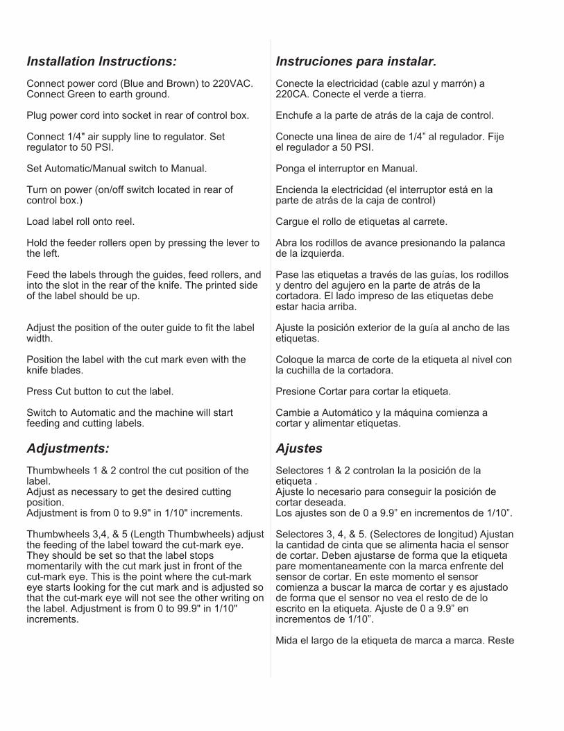
Installation Instructions:
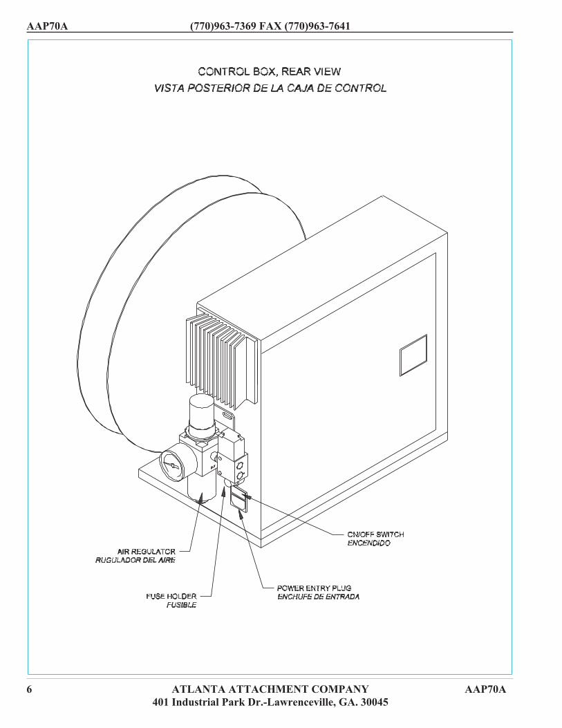
Connect power cord (Blue and Brown) to 220VAC.Connect Green to earth ground.
Plug power cord into socket in rear of control box.
Connect 1/4" air supply line to regulator. Setregulator to 50 PSI.
Set Automatic/Manual switch to Manual.
Turn on power (on/off switch located in rear ofcontrol box.)
Load label roll onto reel.
Hold the feeder rollers open by pressing the lever tothe left.
Feed the labels through the guides, feed rollers, andinto the slot in the rear of the knife. The printed sideof the label should be up.
Adjust the position of the outer guide to fit the labelwidth.
Position the label with the cut mark even with theknife blades.
Press Cut button to cut the label.
Switch to Automatic and the machine will startfeeding and cutting labels.
Adjustments:
Thumbwheels 1 & 2 control the cut position of thelabel.Adjust as necessary to get the desired cuttingposition.Adjustment is from 0 to 9.9" in 1/10" increments.
Thumbwheels 3,4, & 5 (Length Thumbwheels) adjustthe feeding of the label toward the cut-mark eye.They should be set so that the label stopsmomentarily with the cut mark just in front of thecut-mark eye. This is the point where the cut-markeye starts looking for the cut mark and is adjusted sothat the cut-mark eye will not see the other writing onthe label. Adjustment is from 0 to 99.9" in 1/10"increments.
Instruciones para instalar.
Conecte la electricidad (cable azul y marrón) a220CA. Conecte el verde a tierra.
Enchufe a la parte de atrás de la caja de control.
Conecte una linea de aire de 1/4” al regulador. Fijeel regulador a 50 PSI.
Ponga el interruptor en Manual.
Encienda la electricidad (el interruptor está en laparte de atrás de la caja de control)
Cargue el rollo de etiquetas al carrete.
Abra los rodillos de avance presionando la palancade la izquierda.
Pase las etiquetas a través de las guías, los rodillosy dentro del agujero en la parte de atrás de lacortadora. El lado impreso de las etiquetas debeestar hacia arriba.
Ajuste la posición exterior de la guía al ancho de lasetiquetas.
Coloque la marca de corte de la etiqueta al nivel conla cuchilla de la cortadora.
Presione Cortar para cortar la etiqueta.
Cambie a Automático y la máquina comienza acortar y alimentar etiquetas.
Ajustes
Selectores 1 & 2 controlan la la posición de laetiqueta .Ajuste lo necesario para conseguir la posición decortar deseada.Los ajustes son de 0 a 9.9” en incrementos de 1/10”.
Selectores 3, 4, & 5. (Selectores de longitud) Ajustanla cantidad de cinta que se alimenta hacia el sensorde cortar. Deben ajustarse de forma que la etiquetapare momentaneamente con la marca enfrente delsensor de cortar. En este momento el sensorcomienza a buscar la marca de cortar y es ajustadode forma que el sensor no vea el resto de de loescrito en la etiqueta. Ajuste de 0 a 9.9” enincrementos de 1/10”.
Mida el largo de la etiqueta de marca a marca. Reste

(770)963-7369 FAX (770)963-7641 AAP70A
AAP70A ATLANTA ATTACHMENT COMPANY 5401 Industrial Park Dr.-Lawrenceville, GA. 30045
AAP70A (770)963-7369 FAX (770)963-7641
6 ATLANTA ATTACHMENT COMPANY AAP70A401 Industrial Park Dr.-Lawrenceville, GA. 30045
(770)963-7369 FAX (770)963-7641 AAP70A
AAP70A ATLANTA ATTACHMENT COMPANY 7401 Industrial Park Dr.-Lawrenceville, GA. 30045
Measure the length of the label from cut mark to cutmark. Subtract 1-1/2” from that number. Set theresulting number into the Length Thumbwheels.Example: Label length is 2”. 2 – 1-1/2 = 1/2”.Set length thumbwheels to 005 (1/2”)
Thumbwheel 6 controls the cutting mode. In Mode“0" the label machine will feed, cut, and stop with theknife down holding the cut label under the foam pad.When the label is removed the Label Detect Eye willuncover, the knife will raise, and the cycle isrepeated. In Modes “1" through ”9" the machine willcontinue to feed and cut labels until theAutomatic/Manual switch is switched back toManual.
Cut button:
Activates the cutter in Manual only.
Feed button:
Activates the feed motor for one label feed in Manualonly.
Troubleshooting:
Problem:
In Mode “0" unit feeds one label but does not feedsecond label when first label is removed.
Solution:
Label Detect Eye was not covered when first labelwas fed. Check adjustment of Label Detect Eye (seebelow). Eye should be “light” with no label presentand go “dark” when label is fed and cut. SwitchAutomatic/Manual switch to Manual and back toAutomatic to restart the machine.
Problem:
Label feeds past cut mark and stopswithout cutting.
Solution:
Cut-mark eye did not see cut mark. Readjustthumbwheels 3, 4, & 5 as described above orreadjust Cut-Mark Eye Amplifier “set” point asdescribed below. Switch Automatic/Manual switch toManual and back to Automatic to restart themachine.
1-1/2” de este número. El resultado es el númeroque se fija en los selectores..Ejemplo: El largo de la etiqueta es 2”. 2”- 1 1/2”=1/2”.Fije los selectores a 005 (1/2”).
El selector 6 controla el corte. En “0” la máquinaalimenta, corta y para con la cuchilla abajomanteniendo la etiqueta cortada debajo de elcolchoncito de espuma. Cuando se quita la etiquetael sensor de la etiqueta es descubierto, la cuchillasube y el ciclo se repite.En modalidades del “1” al “9” la máquina continuaalimentando y cortando hasta que la máquina sevuelve a poner en Manual.
Botón de cortar:
Activa el cortador en Manual solamente.
Alimentador:
Activa el motor de alimento por solo una etiqueta. EnManual solamente.
Solución a problemas.
Problema:
En modalidad “0” la máquina alimenta una etiqueta,pero no alimenta otra después que la primera hasido removida.
Solución:
El sensor detector de la etiqueta no estaba cubiertocuando la primera fué alimentada. Revise el ajustedel sensor (Vea abajo). El sensor debe estar“encendido” (luz LED) cuando no hay etiqueta y“apagado” cuando la etiqueta es alimentada ycortada. Cambie el interruptor a Manual y otra vez aautomático para recomenzar la máquina.
Problema:
La etiqueta es alimentada pasando la marca decorte y para sin cortar.
Solución:
El sensor no “vio” la marca de cortar. Ajuste losselectores 3, 4 y 5 como se describió anteriormenteo reajuste el ”punto de referencia” del amplificadordel sensor como se describe abajo. Cambie elinterruptor a Manual y otra vez a Automático pararecomenzar la máquina.
Problema
AAP70A (770)963-7369 FAX (770)963-7641
8 ATLANTA ATTACHMENT COMPANY AAP70A401 Industrial Park Dr.-Lawrenceville, GA. 30045
Problem:
Label feeds cut mark to cut-mark eye and stops orstops at other writing on label without cutting.
Solution:
Cut-mark eye was “dark” at end of first feedingmotion. Check adjustment of thumbwheels 3, 4, & 5or readjust cut-mark eye amplifier “set” point asdescribed below in”Quick Set Up”. SwitchAutomatic/Manual switch to Manual and back toAutomatic to restart the machine.
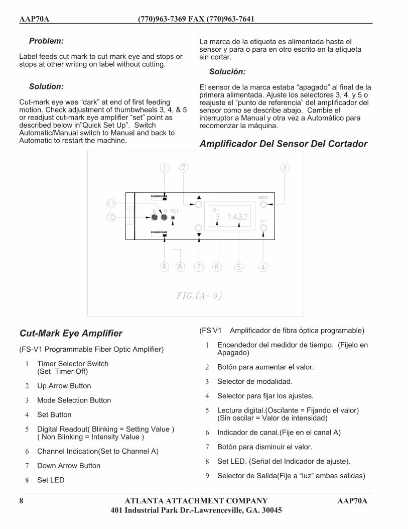
Cut-Mark Eye Amplifier
(FS-V1 Programmable Fiber Optic Amplifier)
1 Timer Selector Switch(Set Timer Off)
2 Up Arrow Button
3 Mode Selection Button
4 Set Button
5 Digital Readout( Blinking = Setting Value )( Non Blinking = Intensity Value )
6 Channel Indication(Set to Channel A)
7 Down Arrow Button
8 Set LED
La marca de la etiqueta es alimentada hasta elsensor y para o para en otro escrito en la etiquetasin cortar.
Solución:
El sensor de la marca estaba “apagado” al final de laprimera alimentada. Ajuste los selectores 3, 4, y 5 oreajuste el ”punto de referencia” del amplificador delsensor como se describe abajo. Cambie elinterruptor a Manual y otra vez a Automático pararecomenzar la máquina.
Amplificador Del Sensor Del Cortador
(FS’V1 Amplificador de fibra óptica programable)
1 Encendedor del medidor de tiempo. (Fijelo enApagado)
2 Botón para aumentar el valor.
3 Selector de modalidad.
4 Selector para fijar los ajustes.
5 Lectura digital.(Oscilante = Fijando el valor)(Sin oscilar = Valor de intensidad)
6 Indicador de canal.(Fije en el canal A)
7 Botón para disminuir el valor.
8 Set LED. (Señal del Indicador de ajuste).
9 Selector de Salida(Fije a “luz” ambas salidas)
(770)963-7369 FAX (770)963-7641 AAP70A
AAP70A ATLANTA ATTACHMENT COMPANY 9401 Industrial Park Dr.-Lawrenceville, GA. 30045
9 Output Selector(Set to Light On Both Outputs)
10 Channel A Output Indicator
11 Channel B Output Indicator
For Further explanation of Fiber Optic Amplifier seethe FS-V1 Instruction Manual
Quick Setup
1 Turn on the machine.
2 Open cover of Amplifier.
3 Be sure Amplifier is set to Channel A (6).Press the Mode (3) and Up Arrow button (2) atthe same time to switch between channel Aand B if necessary.
4 Hold Set button down while moving labelCut-Mark back and forth across eye beam.
5 When the Set LED starts blinking, release theSet button.
6 Close cover of Amplifier.
10 Indicador de salida del Canal A.
11 Indicador de salida del Canal B.
Para más explicaciones acerca del Amplificador defibra óptica vea el manual de instrucciones de laFS-V1.
Configuración Rápida.
1 Encienda la máquina.
2 Abra la cubierta del Amplificador.
3 Asegúrese que el amplificador está fijado en elcanal A (6). Presione “Mode” (3)y el botón de la flecha hacia arriba al mismotiempo para cambiar entre los canales A y B sies necesario.
4 Mantenga el botón SET (4)(Fijar) hundidomientras mueve la marca en la etiqueta haciaadelante y hacia atrás a través del rayo de luz.
5 Cuando el Indicador de ajuste (8) comienza aoscilar, suelte el botón SET (4).
6 Cierre la cubierta del amplificador.
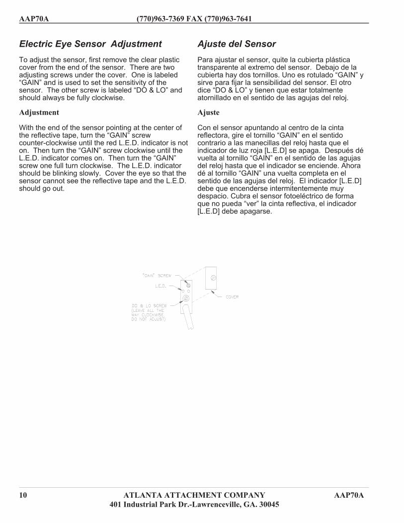
Ajuste del Sensor
Para ajustar el sensor, quite la cubierta plásticatransparente al extremo del sensor. Debajo de lacubierta hay dos tornillos. Uno es rotulado “GAIN” ysirve para fijar la sensibilidad del sensor. El otrodice “DO & LO” y tienen que estar totalmenteatornillado en el sentido de las agujas del reloj.
Ajuste
Con el sensor apuntando al centro de la cintareflectora, gire el tornillo “GAIN” en el sentidocontrario a las manecillas del reloj hasta que elindicador de luz roja [L.E.D] se apaga. Después dévuelta al tornillo “GAIN” en el sentido de las agujasdel reloj hasta que el indicador se enciende. Ahoradé al tornillo “GAIN” una vuelta completa en elsentido de las agujas del reloj. El indicador [L.E.D]debe que encenderse intermitentemente muydespacio. Cubra el sensor fotoeléctrico de formaque no pueda “ver” la cinta reflectiva, el indicador[L.E.D] debe apagarse.
AAP70A (770)963-7369 FAX (770)963-7641
10 ATLANTA ATTACHMENT COMPANY AAP70A401 Industrial Park Dr.-Lawrenceville, GA. 30045
Electric Eye Sensor Adjustment
To adjust the sensor, first remove the clear plasticcover from the end of the sensor. There are twoadjusting screws under the cover. One is labeled“GAIN” and is used to set the sensitivity of thesensor. The other screw is labeled “DO & LO” andshould always be fully clockwise.
Adjustment
With the end of the sensor pointing at the center ofthe reflective tape, turn the “GAIN” screwcounter-clockwise until the red L.E.D. indicator is noton. Then turn the “GAIN” screw clockwise until theL.E.D. indicator comes on. Then turn the “GAIN”screw one full turn clockwise. The L.E.D. indicatorshould be blinking slowly. Cover the eye so that thesensor cannot see the reflective tape and the L.E.D.should go out.

AAP70A ATLANTA ATTACHMENT COMPANY 11401 Industrial Park Dr.-Lawrenceville, GA. 30045
(770)963-7369 FAX (770)963-7641 AAP70A
Part List DirectionsThe following pages contain the appropriate
assembly drawings for this unit.Las páginas siguientes contienen los dibujos
de los ensamblados que hacen parte de esta unidad.
Below is a brief description of the Atlanta Attachment parts list and how to use it.
Debajo hay una descripción de la lista de partes de Atlanta Attachment y como usarla.
Part No. Description Qty. Pg.1 010-047 Belt Idler Assembly 1 2-30
A further break down of the item in questioncan be found on the page listed
Manifiesta sub-división del artículo en cuestiónen ésta página.
This is the quantity of this part no. that wasoriginally used in the assembly process.A “0" denotes an optional item.
Muestra la cantidad de ésta parte.Un “0" denota que es una parte opcional.
A brief description of the part to aid inidentifying it on the drawing. When orderingspare parts be sure to use the part no. as this ishow AAC stocks parts.
Breve descripción de la parte para mejoridentificación en el dibujo. Cuando ordenerepuestos utilice el número de la parte.
The Atlanta Attachment Company partnumber. Be sure to reference this number whenordering spares.
Este es el número de la parte de la CompañiaAtlanta Attachment. Siempre utilice éste númerocuando ordene repuestos.
Refers to the number in the bubble on thedrawing. A number including a decimal denotesa part of a sub-assembly. Example 26.1 is partof sub-assembly 26.A hexagonal bubble denotes connecting parts.
Se refiere al número de la parte en el dibujo.Un número que incluye decimales quiere decirque es parte de un sub-ensamblado. Por ejemplo26.1 hace parte del ensamblado número 26.Losnúmeros en exágonos denotan partes que seconectan.

12 ATLANTA ATTACHMENT COMPANY AAP70A401 Industrial Park Dr.-Lawrenceville,
AAP70A (770)963-7369 FAX (770)963-7641
70-200Metering Head, High Speed
Part No. Description Qty. Pg. Part No. Description Qty Pg.1 1958-7001 Puller, Roller 1
2 28103F Roller, Drive 1
3 28104A Mount, Step Moter 1
4 28105A Outboard Support 1
5 28106 Base 1
6 28107A Arm, Pivot, Dual Spring 1
7 28109B Rod, Straight, 3/16 2
8 28110 Tape Guide 2
9 28112A Support, Roller 1
10 28113A Lever, Pivot Arm 1
11 28113B Arm, Lever Pivot 1
12 28124B Rod, Straight, ¼ 1
13 AP-22E-102 Step Motor, Modified 1
14 MMAS568A202 O-Ring 3
15 RRLC029C10 Spring 2
16 SSFC98032 Screw, Flat Allen 2
17 SSSC90032 Screw, Socket Cap 2
18 SSSC90064 Screw, Socket Cap 2
19 SSSC98032 Screw, Socket Cap 4
AAC Drawing Number 192135C Rev. 0

AAP70A ATLANTA ATTACHMENT COMPANY 13401 Industrial Park Dr.-Lawrenceville, GA. 30045
(770)963-7369 FAX (770)963-7641 AAP70A

14 ATLANTA ATTACHMENT COMPANY AAP70A401 Industrial Park Dr.-Lawrenceville,
AAP70A (770)963-7369 FAX (770)963-7641

