manual electronic controller - guentner...rev.: 2011-08-12 version: 7.1 .0gdr/gird/gistd manual...
TRANSCRIPT

Rev.: 2011-08-12 Version: 7.1 .0GDR/GIRD/GISTD
Manual Electronic Controller
for three-phase motors (microprocessor controlled)
Series: Multifunction GDR 05 IP M
GDR 10 IP M GIRD 05 IP 1...3 M GIRD 10 IP 1...3 M GISTD 24 IP 2 M GISTD 30 IP 3 M

Rev.: 2011-08-12 Page 2 of 38 Version: 7.1 GDR/GIRD/GISTD
Accuracy notes
Work on the devices only may be exported to the avoidance of heavy bodily injuries or considerable damages to property by qualified persons. These persons must carefully read the manual before the installation and getting started. Besides the manual and the national obligatory rules to the accident prevention the recognised technical rules have to be adhered. (UVV, VBG, VDE etc.)
Repairs at the device may done only by persons, which are authorised by the manufacturer for the repair jobs.
The guarantee goes out at opening unauthorised and not qualified interventions!
The speed controllers are assembled in the steel sheet case (protection class IP54). This protection class is guaranteed only at inferred device!
Dangerous electrical voltages lie with open regulation device freely. The protection class of the open device is IP00! At work on regulation devices standing under voltage the valid national accident pre-vention prescriptions (UVV) have to be observed.
Use as agreed
Make sure that fuses may be replaced only in the said strength and not repaired or bridged. Voltage freedom may be checked only with a two-pole voltage indicator. The regulation device is exclusively meant for the tasks agreed in the job acknowledgement. A use which is other or this going beyond valid when not regulation appropriately. The manufacturer isn't liable for damages arising from this. Adhering to the approach described in this manual also is part of the use as agreed at packaging, mode and maintenance. Are the technical data as well as the details on terminal occupations to take from the types signpost and the instruction and to adhere absolutely.
In principle, electronic equipment’s aren't loss safe! The user has to take care for this therefore that his installation is led into a sure status at loss of the device. Damages to body and life as well and assets don't lie in the responsibility of the manufacturer at nonobservance of this point and at im-proper use.
The electrical installation has to be executed after the appropriate prescriptions. Details going out are contained in the documentation on this. If the regulation device in a particular application area comes in use, then the standards demanded for this and regulations have to be adhered absolutely (e.g. EN 50014 and EN 50018).
Indication for the getting started
Before putting into service of the control equipment has to be checked, whether perhaps remains hu-midity scolded himself in this-cabinet has educated himself. The device has yes, so to be dried if. With larger condensed water crowds (Large drops of water on the walls or the components) these have to be removed manually. After the first getting started may the electrical power supply as well as the internal control voltage not switched out a longer time period any more be. Is this mode conditionally neverthe-less required then a suitable humidity protection is to provide.
Rev.: 2011-08-12 Page 3 of 38 Version: 7.1 GDR/GIRD/GISTD
Contents
Page
ACCURACY NOTES ________________________________________________________________________________2
USE AS AGREED __________________________________________________________________________________2
INDICATION FOR THE GETTING STARTED_______________________________________________________________2
1. GENERAL _____________________________________________________________________________________4
1.2 CLASSIFICATION___________________________________________________________________________5 1.3 TRANSPORT, STORAGE AND COPYRIGHT ________________________________________________________5 1.4 GUARANTEE AND LIABILITY __________________________________________________________________5 1.5 MANUFACTURER AND DELIVERING ADDRESS_____________________________________________________6
2. PRIMER ______________________________________________________________________________________6
3. MOUNTING OF THE CONTROLLER__________________________________________________________________9
3.1 EMV ADJUSTED INSTALLATION _______________________________________________________________9 3.2 VENTILATION _____________________________________________________________________________9 3.3 LINE LAYING, SCREENING _________________________________________________________________ 10
4. MAIN AND MOTOR CONNECTION ________________________________________________________________ 10
4.1 AC POWER SUPPLY ______________________________________________________________________ 10 4.2 MOTOR CONNECTION WITH THERMAL CONTACT ________________________________________________ 10 4.3 WEIGHTED NOISE FILTER __________________________________________________________________ 12
5. POTENTIAL-FREE REPORTING OUTPUTS___________________________________________________________ 13
5.1 COMMON FAULT ________________________________________________________________________ 13 5.2 THRESHOLD VALUE ______________________________________________________________________ 13
6. CONTROL INPUTS, RESET _____________________________________________________________________ 14
6.1 CONTROLLER RELEASE ___________________________________________________________________ 14 6.2 FAN SPEED CLIPPING_____________________________________________________________________ 14 6.3 SWITCHOVER ON 2ND REGULATION SYSTEM___________________________________________________ 14 6.4 RESET NONLOCKING KEY_________________________________________________________________ 14
7. SENSOR CONNECTION AND CONTROLLER SETTING __________________________________________________ 15
7.1 DIFFERENCES UNIFUNCTION / MULTIFUNCTION________________________________________________ 15 7.2 THE CONTROL PARAMETERS SET POINT, P-BAND AND THRESHOLD VALUE ___________________________ 15 7.3 THE ADJUST POTENTIOMETERS NIGHT LIMITATION AND MANUAL __________________________________ 17 7.4 CENTRIFUGAL DRIVES ____________________________________________________________________ 18 7.5 SELECTION OF THE REGULATION FUNCTION (ONLY M-CONTROLLER)________________________________ 19 7.6 SENSOR CONNECTION____________________________________________________________________ 23 7.6.1 SENSOR CONNECTION TO REGULATION SYSTEM 1 OR 2__________________________________________ 23 7.6.2 SENSOR CONNECTION TO REGULATION SYSTEM 2 ______________________________________________ 25 7.7 STATUS LED‘S _________________________________________________________________________ 26 7.8 SERVICE DEVICE GSGM __________________________________________________________________ 27
8. SPECIAL FEATURES (NOT IN THE STANDARD EQUIPMENT) ____________________________________________ 27
9. FAULTS AND THEIR REPAIR _____________________________________________________________________ 28
9.1 GENERAL NOTES ________________________________________________________________________ 28
10. TECHNICAL DATA ___________________________________________________________________________ 29
10.1 DIMENSIONS ___________________________________________________________________________ 29 10.2 REPLACEMENT OF FUSES__________________________________________________________________ 29

Rev.: 2011-08-12 Page 4 of 38 Version: 7.1 GDR/GIRD/GISTD
10.3 WIRING DIAGRAM U-CONTROLLER GDR/GIRD ________________________________________________ 30 10.4 WIRING DIAGRAM M-CONTROLLER GDR/GIRD ________________________________________________ 31 10.5 WIRING DIAGRAM M-CONTROLLER GISTD ____________________________________________________ 32 10.6 ELECTRICAL AND MECHANICAL DATA ________________________________________________________ 33
IMAGE DIRECTORY ______________________________________________________________________________ 34
INDEX _______________________________________________________________________________________ 35
GISTD THRESHOLD LEVEL _______________________________________________________________________ 37
TABLE TO THE FAULT DIAGNOSIS __________________________________________________________________ 38
1. General
Regulators of the series of GDR/GIRD ... IP are microprocessor controlled speed controller. They are mounted in a small steel case. The speed control of three-phase motors is carried out after the princi-ple of the phase cut (voltage controlled). The outgoing voltage of the regulator can stepless be adjusted of 0-100 % of the line voltage, and therefore the fan speed 0-100%.
The connected fan motors must be voltage adjustable!
The regulator of the type GISTD is a circuit stage mechanism (up to 3 circuit stages) with direct motor connection. The regulator works as PT1 - regulator (proportional regulator with solid delay time). This is called at the GISTD: To the signal rise (pressure, temp. or input voltage), proportionally becomes the number of levels of the speed controller and increases the number of fan motors switched on with that.
At the two regulator types the rise of the signal input is counteracted so that a constant output value finally is fitted. In principle remains available a deviation which cannot be avoided. By adjusting the set point the operating point can be moved so that the desired pressure, temperature or input voltage can be held.
The divergent device options are described and enclosed with this manual separately at special de-vices. Always keep both papers together!

Rev.: 2011-08-12 Page 5 of 38 Version: 7.1 GDR/GIRD/GISTD
5 = Nominal current of all Motors 5A 10 = Nominal current of all Motors 10A 24 = Nominal current of all Motors 24A 30 = Nominal current of all Motors 30A
Small switch cabinet with electronic fan speed controller for threephase motors
1.2 Classification
GDR GIRD GISTD
X IP
/1 /2 /3 = Number of motor autputs X
M = Multi-function M
Examples:
GDR 5 IPH U = three phase controller (5A) with main switch, Unifunction (1 Motor output)
GIRD 5 IP 2 U = three phase controller (5A) for 2 motor groups, Unifunction, with main switch and motor monitoring
GIRD 10 IP 3 M = three phase controller (10A) for 3 motor groups, Multifunction, with main switch and motor monitoring
GISTD 30 IP 3 U = three phase step switching unit (3 steps), 30A complete nominal current (10A per step), Unifunction, with main switch and Motor monitoring
Special functions aren't included with this device key. An adjustment gave up to special functions by special software settlement is possible in the work for the short term.
1.3 Transport and storage, Indications for the copyright
The regulation devices have a corresponding transport packing. A transport may be carried out only in the original packing. Avoid strokes and pushes at this. Provided that nothing else on the packing is made a note, the maximum batch height amounts to 4 packing. If you take the device in reception, you pay attention to damages of the packing or the regulation device.
You store the device better protected in the original packing and avoid you extreme heat and cold ac-tions.
Technical modifications remain left up to the further development in the interest. Therefore no claims can be derived from the details, figures and subscriptions. Mistake is excepted!
All rights reserved particularly in the case of the patent issue or other entries.
The copyright on this manual remains to:
GÜNTNER AG & CO. KG , Fürstenfeldbruck
1.4 Guarantee and liability
The general sale-and delivery terms of the Hans Güntner GmbH are valid in the respectively valid set-ting.

Rev.: 2011-08-12 Page 6 of 38 Version: 7.1 GDR/GIRD/GISTD
1.5 Manufacturer and delivering address
If you have questions, suggestions or special wishes, you consult to
Güntner AG & Co. KG Hans-Güntner-Straße 2-6
D- 82256 Fürstenfeldbruck
Service phone Germany: 0800 48368637 0800 GUENTNER
Service phone worldwide: +49 (0) 8141 / 242-4810
Fax: +49 (0) 8141/242-422
http://www.guentner.de
Copyright © 2009 Güntner AG & Co. KG
All rights reserved, also those of the photomechanical account and the storage in electronic media.
2. Primer for quick start
The most important details are contained on this page to take the speed controller fast in operation.
This primer replaces under no circumstances the studies of the manual!
Ac power supply: at the terminals L1, L2, L3, PE (400V/50Hz)
Fuses: For the semiconductor and motor protection fine protections are built-in in the controller. Replace these only by the same types (size, current intensity, protec-tion class). Test the fuses only fully developed!*(see page 28 for details)
Motor connection: Motor connection at the output terminals
U1, V1, W1, PE / U4, V4, W4, PE = Motor group 1 (Motor 1+4) U2, V2, W2, PE / U5, V5, W5, PE = Motor group 2 (Motor 2+5) U3, V3, W3, PE / U6, V6, W6, PE = Motor group 3 (Motor 3+6)
Don't exceed at most valid controller nominal current! (=complete nominal cur-rent of all connected motors). +20% are validly for short time, e.g. during the high run phase.
Thermal contact: For every motor connection 2 thermal contact terminals are available to be able to switch the motor in the interference case off. Not used thermal contacts „TK“ must be shorted!
Fault report: At an interference the fault relay is switched , i.e. the relay contact 11/12 closes. (e.g. at motor overheat, sensor defect or network error)
Threshold: Is the threshold value Xe of the active regulation system exceeded this switches of threshold relay (i.e. relay contact 21/22 closes). You occur for Bypass wiring mostly. This isn't an interference!
Controller release: If the terminal „FG“ is connected to +24 V (terminal „P“), the controller is re-leased (green LED „Run“ is on), in other way the controller is disabled (LED out). No connection to extern voltage! Use only voltage free contacts for release input! Isn't the external release needed this port is with terminal „P“ last to straps!

Rev.: 2011-08-12 Page 7 of 38 Version: 7.1 GDR/GIRD/GISTD
Clipping: Is the terminal „NB“ connected to +24 V (terminal „P“) the controller outgoing voltage is clipped to the voltage adjusted at Poti „Begrenzg.“. The Poti works di-rect to the power supply and doesn't have any effects on the regulation circuit.
System switchover (only M-Regulator): Gets the terminal „RS2“ connected to +24V (terminal „P“), the regulation sys-tem 2 becomes active. In other way, regulation system 1 is active.
Regulation function (only M-Regulator): The select switch determines the regulation function:
Pos.1 (left) = MAX-select: 2 Sensors, 2 regulation systems both RS active, higher regulation signal sets fanspeed Pos.2 (middle) = set point switch: 1 sensor, 2 regulation systems Pos.3 (right) = system switch: 2 sensors, 2 regulation systems
RESET- Nonlocking key: If the controller works no longer correctly, you push this nonlocking key briefly. A controller blocking by repeated motor fault becomes hereby also raised.
Sensor connection: Sensor for regulation system RS1 on terminal ES1 (Eingangs-Signal 1):
pressure transmitter GSW4003 (4-20mA): „+24V“ = supply voltage (wire ‘1’) „1B1“ and/or „1B2“ = signal 4-20mA (wire ‘2’) temperature probe GTF210: „GND“ = brown wire „1B3“ = white wire standard signal 0-10V: „GND“ = ground „1Y“ = signal 0-10V
Sensor for regulation system RS2 on terminal ES2 (Eingangs-Signal 2) (only M-Controller):
pressure transmitter GSW4003 (4-20mA): „+24V“ = supply voltage (wire ‘1’) „2B1“ and/or „2B2“ = signal 4-20mA (wire ‘2’) temperature probe GTF210: „GND“ = brown wire
„2B3“ = white wire standard signal 0-10V: „GND“ = ground „2Y“ = signal 0-10V
The sensor type must be select on switch „ES1“ and „ES2“:
Above = pressure, middle = 0-10V, below = temperature
Adjusting the controller:
Both regulation systems are identical functionally and have an effect on the same power output:
set point Xs: The set point determines the cut-off of the fan speed control. If this point is ex-ceeded, the controller creates an outgoing voltage (At begin still low: motor start only as of approx. 30-40 V, motor typical)
P-Band Xp: With the P-Band the workspace of the controller is adjusted. This value marks the end of the regulation range going out of the set point.
Example: Set point = 12 bar, P-Band = 4 bar == > workspace = 12-16 bar.
threshold Xe: Has no effect to the regulation circuit, sets only the switch point for the thresh-old relay. Exceeds the sensor signal the threshold value of the active regulation system, contact 21/22 closes.

Rev.: 2011-08-12 Page 8 of 38 Version: 7.1 GDR/GIRD/GISTD
manual button: A minimum outgoing voltage can hereby be adjusted. Serves for test and exam-ining purposes as hand plate, must otherwise stand on 0%!
clipping: The outgoing voltage hereby is limited, i.e. the outgoing voltage adjusted here isn't exceeded any more (in % of the main voltage, i.e. 50%=200V). External ac-tivation with terminal „NB“ necessary.
Rev.: 2011-08-12 Page 9 of 38 Version: 7.1 GDR/GIRD/GISTD
3. Mounting of the controller, line laying
3.1 EMV adjusted installation
The controller of the series GDR/GIRD/GISTD...IP fulfil the requirements of EMV- Interference immunity appropriate EN 50082-2 and disturbing emission appropriate EN 50081-1. The respectively stricter standard is fulfilled with that. To guarantee this EMV compatibility, the following points have to be ob-served:
• The device must be grounded well
• All of them measure- and signal lines must be screened. Using only measuring wires, e.g. LIYCY 3x0.5², no telephone lines!
⇒ The screening of the signal lines must single end to ground. ⇒ Grounding the screening of motor wires on both sides
• Signal and control lines have to be transferred by main and motor wires separated, e.g. in separate cable channels.
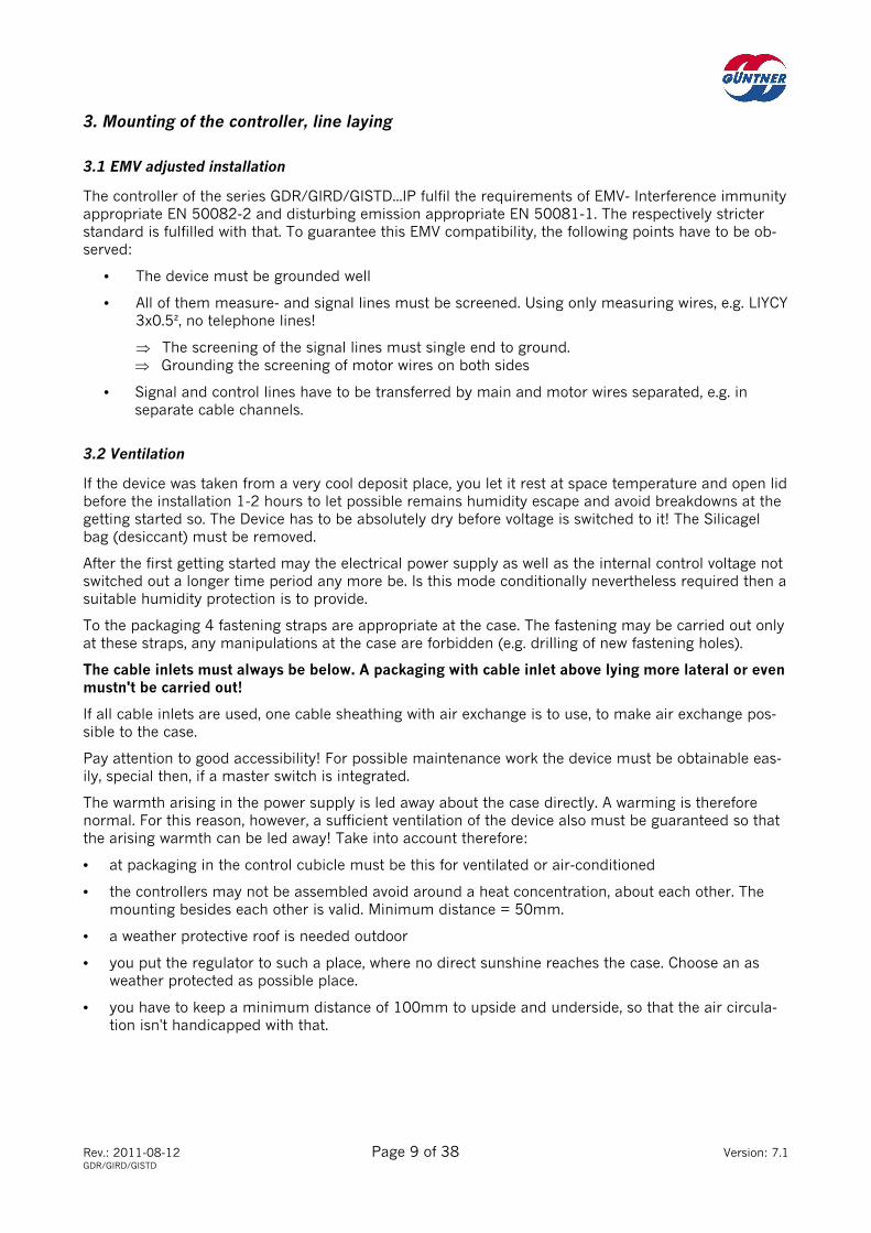
3.2 Ventilation
If the device was taken from a very cool deposit place, you let it rest at space temperature and open lid before the installation 1-2 hours to let possible remains humidity escape and avoid breakdowns at the getting started so. The Device has to be absolutely dry before voltage is switched to it! The Silicagel bag (desiccant) must be removed.
After the first getting started may the electrical power supply as well as the internal control voltage not switched out a longer time period any more be. Is this mode conditionally nevertheless required then a suitable humidity protection is to provide.
To the packaging 4 fastening straps are appropriate at the case. The fastening may be carried out only at these straps, any manipulations at the case are forbidden (e.g. drilling of new fastening holes).
The cable inlets must always be below. A packaging with cable inlet above lying more lateral or even mustn't be carried out!
If all cable inlets are used, one cable sheathing with air exchange is to use, to make air exchange pos-sible to the case.
Pay attention to good accessibility! For possible maintenance work the device must be obtainable eas-ily, special then, if a master switch is integrated.
The warmth arising in the power supply is led away about the case directly. A warming is therefore normal. For this reason, however, a sufficient ventilation of the device also must be guaranteed so that the arising warmth can be led away! Take into account therefore:
• at packaging in the control cubicle must be this for ventilated or air-conditioned
• the controllers may not be assembled avoid around a heat concentration, about each other. The mounting besides each other is valid. Minimum distance = 50mm.
• a weather protective roof is needed outdoor
• you put the regulator to such a place, where no direct sunshine reaches the case. Choose an as weather protected as possible place.
• you have to keep a minimum distance of 100mm to upside and underside, so that the air circula-tion isn't handicapped with that.
Rev.: 2011-08-12 Page 10 of 38 Version: 7.1 GDR/GIRD/GISTD
3.3 Line laying, Screening
For the motor wire no screened line is specified.
Control lines must be transferred screenedly, if they are immediately transferred with other lines or are longer than 20 m. Through this the one coupling is avoided by interfering signals. The wire screen-ing then must get as short as connected to terminal 'PE' possibly.
In principle, sensor lines are separated from the motor and too embarrassed therefore not in one com-mon to mains power lines cable channel. Screened wire is recommended.
4. Main and motor connection
The motor connection terminals and the potential-free reporting outputs are on the lower power board. The connections find the control inputs and sensors to be himself on the upper controller board (Con-troller release etc.).
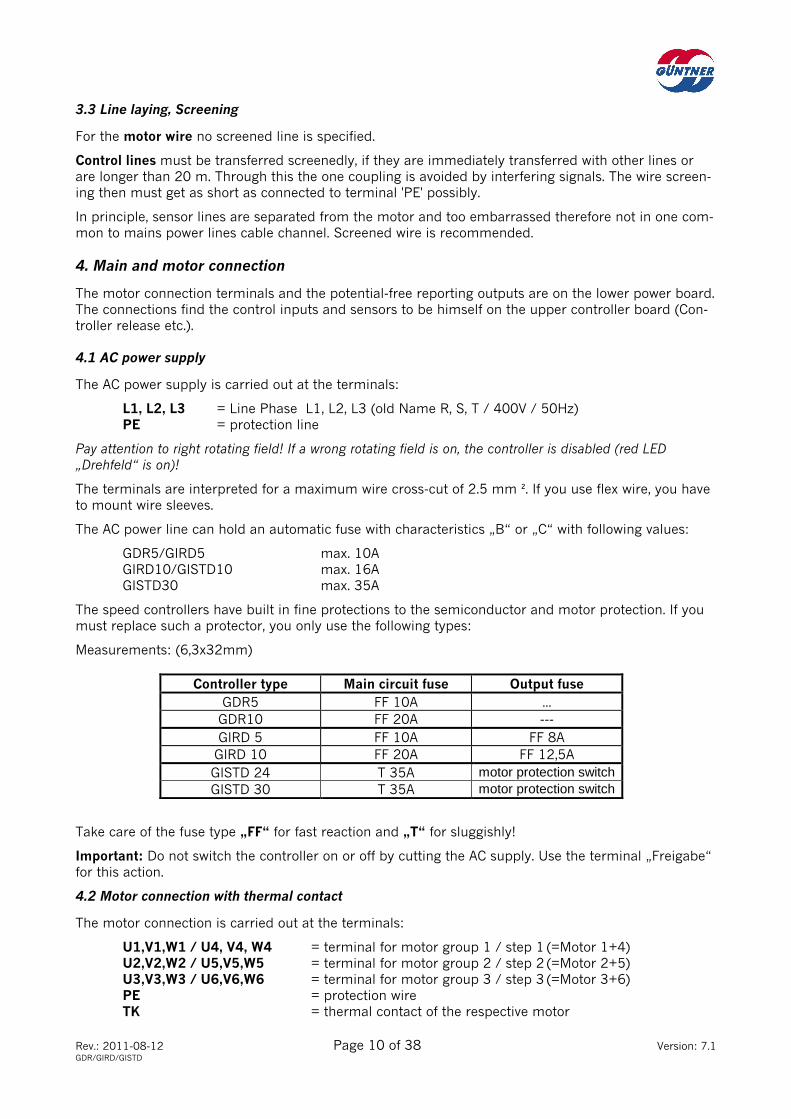
4.1 AC power supply
The AC power supply is carried out at the terminals:
L1, L2, L3 = Line Phase L1, L2, L3 (old Name R, S, T / 400V / 50Hz) PE = protection line
Pay attention to right rotating field! If a wrong rotating field is on, the controller is disabled (red LED „Drehfeld“ is on)!
The terminals are interpreted for a maximum wire cross-cut of 2.5 mm ². If you use flex wire, you have to mount wire sleeves.
The AC power line can hold an automatic fuse with characteristics „B“ or „C“ with following values:
GDR5/GIRD5 max. 10A GIRD10/GISTD10 max. 16A GISTD30 max. 35A
The speed controllers have built in fine protections to the semiconductor and motor protection. If you must replace such a protector, you only use the following types:
Measurements: (6,3x32mm)
Controller type Main circuit fuse Output fuse GDR5 FF 10A ...
GDR10 FF 20A ---
GIRD 5 FF 10A FF 8A
GIRD 10 FF 20A FF 12,5A
GISTD 24 T 35A motor protection switch
GISTD 30 T 35A motor protection switch
Take care of the fuse type „FF“ for fast reaction and „T“ for sluggishly!
Important: Do not switch the controller on or off by cutting the AC supply. Use the terminal „Freigabe“ for this action.
4.2 Motor connection with thermal contact
The motor connection is carried out at the terminals:
U1,V1,W1 / U4, V4, W4 = terminal for motor group 1 / step 1 (=Motor 1+4) U2,V2,W2 / U5,V5,W5 = terminal for motor group 2 / step 2 (=Motor 2+5) U3,V3,W3 / U6,V6,W6 = terminal for motor group 3 / step 3 (=Motor 3+6) PE = protection wire TK = thermal contact of the respective motor

Rev.: 2011-08-12 Page 11 of 38 Version: 7.1 GDR/GIRD/GISTD
Two terminals 'TK' are part of every motor connection. In principle, is valid:
TK terminals not used must become shorted!
Pay attention to the correct direction of movement of the fan! A right rotating field is always on at the terminals U, V, W.
Noticing you: Only the port is of voltage adjustable motors validly!
If you have doubts about the usability of the motor, you ask the manufacturer so whether a mode is possible.
The speed controllers have so called double floor terminals for the motor connection, i.e. per port, 2 motors can be connected directly (See following image).
However, this also indicates that per quantity issued ports are available for 2 thermal contacts! If you connect only one motor, then the thermal contact for the second motor must become shortened. The controller otherwise permanently reports a motor fault although the motor is all right.
All available TK terminals ex works are shortened. You only then remove a wire bridge, if a motor is there also actually connected with motor protection.
If several motors must be connected to a output terminal, the following has to be taken into account:
• The thermal contacts of the motors must be connected in series!
• The complete motor nominal current may not cave's valid controller nominal current exceed!
• Connect the motor wires in suitable job and put no more wires into the terminals with force!
At the closed-loop control of fans by means of phase cut (GDR/GIRD) vibrations arise, which can make himself noticeable, as motor noise. These however don't affect the motor function and life time nega-tively. At extreme requirements on the weighted noise issue controllers with transformers have to be preferred, which produce no motor noise.
illus. 4.2.1.: AC line and motor connection
You see the connection of max. 6 motors to an GIRD -3. On e.g. an GIRD -2 you can connect max. 4 motors.
ABB 4-2-1
W4V4U4PE
W1V1U1PE
W5V5U5PE
W2V2U2PE
W6V6U6PE
W3V3U3PEPEL3L2L1
M43~
M53~
M63~
3Ph. 400V 50Hz
M13~
TK TK PE U1 V1 W1
M23~
TK TK PE U2 V2 W2
M33~
TK TK PE U3 V3 W3
Motor(group) 2Motor(group) 3 Motor(group) 1
F2 F2 F2F3 F3 F3 F1 F1 F1
Series connectionof the TK terminals
free clamp pairsmust be shortened!
Rev.: 2011-08-12 Page 12 of 38 Version: 7.1 GDR/GIRD/GISTD
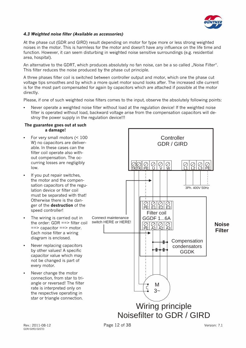
4.3 Weighted noise filter (Available as accessories)
At the phase cut (GDR and GIRD) result depending on motor for type more or less strong weighted noises in the motor. This is harmless for the motor and doesn't have any influence on the life time and function. However, it can seem disturbing in weighted noise sensitive surroundings (e.g. residential area, hospital).
An alternative to the GDRT, which produces absolutely no fan noise, can be a so called „Noise Filter“. This filter reduces the noise produced by the phase cut principle.
A three phases filter coil is switched between controller output and motor, which one the phase cut voltage tips smoothes and by which a more quiet motor sound looks after. The increased idle current is for the most part compensated for again by capacitors which are attached if possible at the motor directly.
Please, if one of such weighted noise filters comes to the input, observe the absolutely following points:
• Never operate a weighted noise filter without load at the regulation device! If the weighted noise filter is operated without load, backward voltage arise from the compensation capacitors will de-stroy the power supply in the regulation device!!!
The guarantee goes out at such a damage!
• For very small motors (< 100 W) no capacitors are deliver-able. In these cases can the filter coil operate also with-out compensation. The oc-curring losses are negligibly low.
• If you put repair switches, the motor and the compen-sation capacitors of the regu-lation device or filter coil must be separated with that! Otherwise there is the dan-ger of the destruction of the speed controller!
• The wiring is carried out in the order: GDR ==> filter coil ==> capacitor ==> motor. Each noise filter a wiring diagram is enclosed.
• Never replacing capacitors by other values! A specific capacitor value which may not be changed is part of every motor.
• Never change the motor connection, from star to tri-angle or reversed! The filter rate is interpreted only on the respective operating in star or triangle connection.
M3~
3Ph. 400V 50Hz
Wiring principleNoisefilter to GDR / GIRD
NoiseFilter
Filter coilGGDF 1...6A
E3E2E1PE
A3A2A1PE
Compensationcondensators
GGDK
Connect maintenanceswitch HERE or HERE!
WVUPE
ControllerGDR / GIRD
PEL3L2L1
Rev.: 2011-08-12 Page 13 of 38 Version: 7.1 GDR/GIRD/GISTD
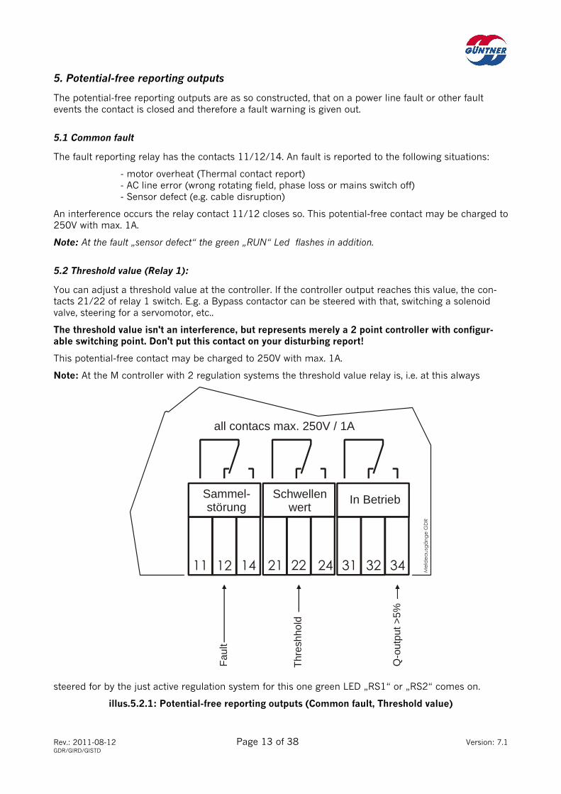
5. Potential-free reporting outputs
The potential-free reporting outputs are as so constructed, that on a power line fault or other fault events the contact is closed and therefore a fault warning is given out.
5.1 Common fault
The fault reporting relay has the contacts 11/12/14. An fault is reported to the following situations:
- motor overheat (Thermal contact report) - AC line error (wrong rotating field, phase loss or mains switch off) - Sensor defect (e.g. cable disruption)
An interference occurs the relay contact 11/12 closes so. This potential-free contact may be charged to 250V with max. 1A.
Note: At the fault „sensor defect“ the green „RUN“ Led flashes in addition.
5.2 Threshold value (Relay 1):
You can adjust a threshold value at the controller. If the controller output reaches this value, the con-tacts 21/22 of relay 1 switch. E.g. a Bypass contactor can be steered with that, switching a solenoid valve, steering for a servomotor, etc..
The threshold value isn't an interference, but represents merely a 2 point controller with configur-able switching point. Don't put this contact on your disturbing report!
This potential-free contact may be charged to 250V with max. 1A.
Note: At the M controller with 2 regulation systems the threshold value relay is, i.e. at this always
steered for by the just active regulation system for this one green LED „RS1“ or „RS2“ comes on.
illus.5.2.1: Potential-free reporting outputs (Common fault, Threshold value)
Sammel-störung
Schwellenwert
In Betrieb
11 12 14 21 22 24 31 32 34
all contacs max. 250V / 1A
Fau
lt
Thr
eshh
old
Q-o
utpu
t >5%

Rev.: 2011-08-12 Page 14 of 38 Version: 7.1 GDR/GIRD/GISTD
6. Control inputs, Reset
The control inputs are constructed only for 24V. They must be used with potential-free contacts (Relay, contactor contact, switch...). They have to be connected between the control input and the +24V terminal „P“.
You may under no circumstances create the line voltage here or work with another foreign voltage!
6.1 Controller release
About the terminal „FG“ the controller is unlocked. If this termi-nal gets connected to +24 V, the controller is unlocked, and the green LED „Run“ shines.
If this terminal is disconnected, the controller is locked and the LED goes out. The power output then is switched off. No more outgoing voltage is created.
illus. 6.1.1.: Port of the external release contact
If the release function isn't needed, connect this terminal by a wire link to +24V!
The release strap is ex works always mounted.
Essential note: You may under no circumstances close the con-troller by the fact that you interrupt the line voltage! Switching the line voltage permanently can lead to damages to the con-troller. There isn't a right to claim under guarantee at such damages!
6.2 Fan speed clipping (Night clipping)
About the terminal „NB“ the night clipping is acti-vated if it is connected to +24V. The controller out-going voltage then becomes and thus also limits the fan speed on the value adjusted at the Potentiome-ter „Begrenzg.“. (See chapter „Adjusting the controller“).
illus. 6.2.1: Activating the fan speed clipping with a potential-free contact
6.3 Switchover on 2nd regulation system (Only M-Controller!)
About the terminal „RS2“ you change to the second regulation system, i.e. the closed-loop control is exclusively carried out with the parameters of RS2.
illus. 6.3.1: Changing from RS1 to RS2 with a potential-free contact
If this terminal is disconnected, RS1 is always active. This port is work-sided disconnectedly.
6.4 RESET- Nonlocking key
With the RESET nonlocking key the regulation device is reset and started newly on a defined status. If the controller was dis-turbed by extreme outer influences and works no longer cor-rectly, you push this nonlocking key briefly.
ABB 6-2-1 FG
NB
RS
2P
On one side
max. 100m2 x 0,75mm2
Night clipping
ABB 6-3-1 FG
NB
RS
2P
On one side
max. 100m2 x 0,75mm2
ABB 6-1-1 FG
NB
RS
2P
Ext.Freigabe(Release)
On one side
max. 100m2 x 0,75mm2

Rev.: 2011-08-12 Page 15 of 38 Version: 7.1 GDR/GIRD/GISTD
7. Sensor connection and controller setting
7.1 Differences Unifunction / Multifunction (GDR...U and M)
The Unifunction speed controller has one regulation system and one sensor input. The multifunction speed controller has two regulation systems and two sensor inputs.
Every sensor input can be provided with 1-2 pressure transmitters or one temperature probe or one standard signal 0-10V (switch-selectable any time at the controller).
Both regulation systems are identical in her function absolutely and control a power supply.
The selection of the controller type is carried out because of the respective requirements on the closed-loop control to be needed:
• At a liquid cooler with one cooling circuit (= 1 temperature probe) or a condenser with 1-2 cooling circuits (= 1-2 pressure transmitters) and same liquefaction pressure a U type can be used since one regulation system suffices here.
• As soon as you have several circulation’s, a set point switchover (summer/winter mode) is needed or 2 different liquids are used, you need a M type. If later modifications can be foreseen at the in-stallation, a M-controller is also to provide.
7.2 The control parameters Set point and P-Band
For the setting of the controller the three adjust potentiometer Set point Xs and P-Band Xp are avail-able:
Set point Xs:
The set point determines the cut-off of the closed-loop control. As of this value the regulation system starts to work and a regulation signal Q is created. This is led to the power output where an outgoing voltage is created. Since this is however still low at begin, the motor doesn't immediately run since the outgoing voltage reaches 30-40V. If a run of the motor early gets desired, the set point must be re-duced a little.
At the GISTD the switch steps are activated corresponding to the regulation signal.
The set point is configurable in the area of 0-100 % and refers to the measurement range of the con-nected sensor:
Pressure transmitter 0-25bar: 0-100% = 0... 25bar rel. Temperature probe GTF210: 0-100% = -30..+70°C Standard signal 0-10V: 0-100% = 0... 10V
Set Point Xs Pressure (rel.) Temperature Standard signal
0% 0,0 bar -30°C 0,0 V
10% 2,5 bar -20°C 1,0 V
20% 5,0 bar -10°C 2,0 V
30% 7,5 bar +0°C 3,0 V
40% 10,0 bar +10°C 4,0 V
50% 12,5 bar +20°C 5,0 V
60% 15,0 bar +30°C 6,0 V
70% 17,5 bar +40°C 7,0 V
80% 20,0 bar +50°C 8,0 V
90% 22,5 bar +60°C 9,0 V
100% 25,0 bar +70°C 10,0 V
Rev.: 2011-08-12 Page 16 of 38 Version: 7.1 GDR/GIRD/GISTD
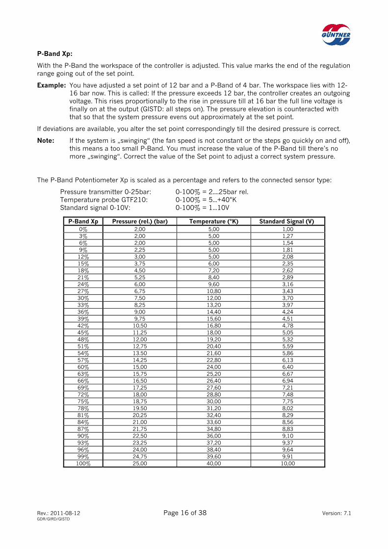
P-Band Xp:
With the P-Band the workspace of the controller is adjusted. This value marks the end of the regulation range going out of the set point.
Example: You have adjusted a set point of 12 bar and a P-Band of 4 bar. The workspace lies with 12-16 bar now. This is called: If the pressure exceeds 12 bar, the controller creates an outgoing voltage. This rises proportionally to the rise in pressure till at 16 bar the full line voltage is finally on at the output (GISTD: all steps on). The pressure elevation is counteracted with that so that the system pressure evens out approximately at the set point.
If deviations are available, you alter the set point correspondingly till the desired pressure is correct.
Note: If the system is „swinging“ (the fan speed is not constant or the steps go quickly on and off), this means a too small P-Band. You must increase the value of the P-Band till there’s no more „swinging“. Correct the value of the Set point to adjust a correct system pressure.
The P-Band Potentiometer Xp is scaled as a percentage and refers to the connected sensor type:
Pressure transmitter 0-25bar: 0-100% = 2....25bar rel. Temperature probe GTF210: 0-100% = 5...+40°K Standard signal 0-10V: 0-100% = 1...10V
P-Band Xp Pressure (rel.) (bar) Temperature (°K) Standard Signal (V) 0% 2,00 5,00 1,00
3% 2,00 5,00 1,27
6% 2,00 5,00 1,54 9% 2,25 5,00 1,81
12% 3,00 5,00 2,08 15% 3,75 6,00 2,35 18% 4,50 7,20 2,62 21% 5,25 8,40 2,89 24% 6,00 9,60 3,16 27% 6,75 10,80 3,43 30% 7,50 12,00 3,70 33% 8,25 13,20 3,97 36% 9,00 14,40 4,24 39% 9,75 15,60 4,51 42% 10,50 16,80 4,78 45% 11,25 18,00 5,05 48% 12,00 19,20 5,32 51% 12,75 20,40 5,59 54% 13.50 21,60 5,86 57% 14,25 22,80 6,13 60% 15,00 24,00 6,40 63% 15,75 25,20 6,67 66% 16,50 26,40 6,94 69% 17,25 27,60 7,21 72% 18,00 28,80 7,48 75% 18,75 30,00 7,75 78% 19.50 31,20 8,02 81% 20,25 32,40 8,29 84% 21,00 33,60 8,56 87% 21,75 34,80 8,83 90% 22,50 36,00 9,10 93% 23,25 37,20 9,37 96% 24,00 38,40 9,64 99% 24,75 39,60 9,91
100% 25,00 40,00 10,00

Rev.: 2011-08-12 Page 17 of 38 Version: 7.1 GDR/GIRD/GISTD
Threshold value Xe:
The threshold value is independent of the closed-loop control and has no influence on this. You adjust only the switching point for the threshold value relay (relay 1). If the sensor signal exceeds the value adjusted here, the relay contact 21/22 closes.
Attention: The threshold value relay switches at speed controller with the added feature „reversed characteristic (heating)“ at under run of the threshold value not at transgression! (See chapter 8.6)
The adjustment range refers to the measurement range of the connected sensor also here (Xe equal to Xs, see Page 14).
Application examples:
Example 1: Bypass wiring
With the threshold value relay a bypass contactor is connected, which connects the controller output with the power supply directly. (Controller detour).
Look for the right supply phase connection!!! U on L1, V on L2, W on L3!!!
Bypass contactor is connected so this, that it puts on when closing the contacts 21/22.
With this measure you obtain an additional accuracy:
• If the sensor signal rises about the oriented limiting value now, e.g. the output of the controllers is faulty, the fans get direct under detour of the controller at the power supply (2 point regulation mode).
• Even if the controller is suddenly current-free, a emergency mode is guaranteed to the installation.
Example 2: Fan mode report
If you need a mode report for the fans, you can create this with the threshold value relay:
Put the threshold value exactly at once one like the set point, i.e. if the set point Xs stands on 12 bar, you move the threshold value Xe to 12 bar also. The threshold value relay switches now as soon as the controller creates an outgoing voltage for the fans.
Note: The threshold value of the just active regulation system is always effective at the M controller with 2 regulation systems. You recognise this for LED for „RS1“ or „RS2“ corresponding to this one at coming on.
7.3 The adjust potentiometers Night limitation and Manual
These two Potentiometer have only an effect to the power output and not to the regulation circuit. You can take the item of the Potentiometer from the graphic in chapter 7.5.
Clipping:
With the potentiometer „Begrenzg.“ the internal regulation signal Q will be limited. The signal Q steers the Power output. Well, the outgoing voltage or the circuit stage number is also limited with that auto-matically. The voltage adjusted here or circuit stage number isn't exceeded by the controller any more. The Potentiometer is scaled as a percentage and refers to the line voltage (0-100% = 0-400V):
• At 100% the maximum outgoing voltage is at 400V or all circuit stage numbers are switched. No limitation.
• At 50% the maximum outgoing voltage is at 200 V. The clipping is at 50%.
• At 0% the controller finally creates no more outgoing voltage. The clipping is at 100%.
To activate the clipping, the terminal „NB“ must be connected over an external potential-free contact to +24V. If the terminal „NB“ is disconnected, the outgoing voltage isn't limited and no function has the potentiometer.

Rev.: 2011-08-12 Page 18 of 38 Version: 7.1 GDR/GIRD/GISTD
You proceed for adjusting practically as follows:
• adjust the potentiometer „Sockelspannung“ to 100%. All fans run with full speed now.
• activate the night limit (e.g. wire link between NB and P)
• Now adjust the correct fan speed (or steps) with the potentiometer „Begrenzg.“.
• Put back the potentiometer „Sockelspannung“ to 0% and remove the wire link. That’s all!
Manual Button (Sockelspannung):
With the manual button „Sockelspg.“ a minimum outgoing voltage or minimum circuit stage number can be adjusted. With these minimum rotational speed the fan runs as soon as the controller is unlocked even if the regulation signal zero is.
This function can serve for examining purposes (e.g. at the getting started) as hand plate, at normal regulation function this Potentiometer must stand on 0%!
You can for example check and state the direction of rotation of the fan whether the power output of the controller works.
The potentiometer is scaled as a percentage and refers to the line voltage (400V or 230V):
• At 100% the full line voltage lies at the controller output or all circuit stages are on. The fans per-manently work with full speed.
• At 50% the voltage is 200 V. Since fan motors have a square power characteristic, half voltage doesn't indicate halved rotational speed automatically either! If you liked to provide definite mini-mum rotational speed with the pedestal voltage, this most simply lets himself obtain by practical trials.
• At 0% no more pedestal voltage on and no minimum outgoing voltage at the controller output. (all circuit stages off) . This also corresponds to the work setting for normal regulation mode.
7.4 Centrifugal drives (Wedge belt-drive)
The standard function „centrifugal drive“ isn't available, if a controller with the added features „Day Clipping“ or „Outside temperature dependent set point switchover“ is ordered. This applies general to all controllers with added features, who use the potentiometer „Sonderfkt.“.
Centrifugal drives (Wedge belt-drives) have a high breaking torque constructively causes, well need a definite minimum voltage to begin. The controller at first one creates little outgoing voltage, this there-fore doesn't immediately let the motor run. The voltage must rise so far first till the breaking torque of the dial mechanism is exceeded. Till there the motor however is blocked. A motor current increased strongly flows. On the whole this one can rise, that the motor and/or the regulation device are de-stroyed.
To prevent this the outgoing voltage of the controller may not a minimum value lower-stride. At regula-tion begin a minimum voltage which for certain starts the motor must already be provided.
You set the minimum outgoing voltage at the potentiometer „Special Function“ (Sonderfkt.), which works exactly like the manual button „Sockelspang.“. The only difference is, that this minimum outgo-ing voltage is only then activated, when the set point is exceeded. The manual button creates an outgo-ing voltage permanently. The potentiometer „Special Function“ is scaled in %.
0..100% = 0...400V

Rev.: 2011-08-12 Page 19 of 38 Version: 7.1 GDR/GIRD/GISTD
Adjusting the Potentiometer „Special Function“ for centrifugal fans:
1. Release the controller (Link terminals FG and P)
2. If Night Limitation is used, deactivate it (remove wire at terminal NB)
3. Deactivate all sensor signals (remove sensor terminal connector)
4. Use the potentiometer „Sockelspg.“ (manual button) to find out at which percentage the fan runs with a slow basic speed and starts for sure when the controller is released.
5. Test this several times (via Controller-Release)!
6. Set the potentiometer „Special Funct.“ for the centrifugal fan to this percentage
7. Set „Sockelspannung“ (manual button) back to 0%
Please notice: Don't adjust the bottom revolutions per minute for the centrifugal drive with the normal pedestal voltage (Poti on the left), but only with the right Poti „Sonderfkt.“. The fan shall not permanently run, as soon as the controller is unlocked but only then if the sensor signal is in the regulation range.
The radial pedestal voltage must be adjusted at the Poti „Sonderfkt .“ getting started for installa-tions with centrifugal drive!
But: If you don't use any centrifugal drive, this Poti must stand on 0%!
To avoid damages to the motor or controller, the thermal contact must be connected!
IMPORTANT NOTE: If the radial fan motor overheats or the fuses break permanently, although the controller is adjusted correctly, then check the radial pulleys (external static pressure may be wrong: replace the pulley at the radial motor, it must have a smaller diameter than the fan pulley).
7.5 Selection of the regulation function (Only M-Controller!)
Two regulation systems and two sensor inputs are available at the multifunction controller. Every sen-sor input can connected with 1-2 pressure transmitters or 1 temperature probe or 1 standard signal 0-10V. However, you must not contact both inputs but also be able to connect only one sensor. Through this two port possibilities give up:
1 sensor = set point switch (Both regulation systems use the same sensor signal)
2 sensors = regulation system switch (Every regulation system has own sensor)
With the select switch „Regelfunktion“ is adjusted, which class of operation is wished.
Position 1 (left): MAX-Selection (2 sensors) Position 2 (middle): Set point switch (1 sensor) Position 3 (right): System switch (2 sensors)
These 3 variants are explained briefly in the following:
Set point switch:
A common sensor is connected to terminal ES1 (input signal 1) for regulation system RS1 & RS2 at the set point switch.
Adjust the used sensor type at the select switch ES1:
Select switch ES1 Above P (1-2 Pressure transmitter) Middle S (1 Standard signal 0-10V) Below T (1 Temperature probe)
The sensor signal is passed on to RS1 and RS2 to the two regulation systems. Both regulation systems create a regulation signal (Q) after her settings for the outgoing voltage now. Which of these two signals
321
Regelfunktion
PST
ES1

Rev.: 2011-08-12 Page 20 of 38 Version: 7.1 GDR/GIRD/GISTD
is led to the common power supply actually and the rotational speed regulates are defined by the allo-cation of the input terminal „RS2“:
Terminal „RS2“ open (no connection): RS1 active (Set point 1)
Terminal „RS2“ with +24V („P“) linked: RS2 active (Set point 2)
Report the active regulation system to „RS1“ or „RS2“ for the green LED. The threshold value relay is always switched by the just active regulation system also.
If you adjust Xp of both regulation systems to the same value, this corresponds to a pure set point switch (1 sensor, 2 set points).
If you need different characteristics, you can adjust both regulation systems alone understandably also variously.
Application example: Day/night or summer/winter switchover at condenser or liquid cooler.
System switch:
Two sensors are connected at the System switch:
Sensor for regulation system RS1 to terminal ES1 Sensor for regulation system RS2 to terminal ES2
You don't have connect but be able to combine arbitrarily two equal-type sensors. You only take care, that you have adjusted the connected sensor type ES1 and ES2 at the select switch correctly:
Select switch ES1/ES2: above P (1-2 Pressure transmitter) middle S (1 Standard signal 0-10V) below T (1 Temperature probe)
The sensor signal at the terminal ES1 becomes to regulation system RS1 passed on and the sensor signal of ES2 at RS2. Well, both regulation systems are fed by an own sensor.
Both regulation systems create a regulation signal for the outgoing voltage (fan speed), but only one is actually led to the common power supply by them. This is which of these two signals, is defined by the allocation of the input terminal „RS2“:
Terminal „RS2“ open (not connected): RS1 controls fan speed Terminal „RS2“ with +24V („P“) linked: RS2 controls fan speed
It is shown by the green LED „RS1“ or „RS2“. The threshold value relay is always switched by the just active regulation system also.
MAX-Selection:
The Max selection corresponds exactly to the System switch: 2 regulation systems, 2 sensors. The dif-ference lies in the treatment of the two regulation signals:
It isn't switched over externally between the two regulation systems but the respectively larger regula-tion signal is consulted automatically to the speed control.
To the regulation system switch the terminal „RS2“ becomes ignored at this.
Application example: A heat exchanger with two circles and various cold means. The pressure in the two circles is included by an own pressure transmitter and both circles need various characteristics for the fan speed.
The circle with the larger regulation signal gains acceptance either automatic (= Max selection) and determines the fan speed or the active regulation system is provided externally (=System switchover).
PST
Rev.: 2011-08-12 Page 21 of 38 Version: 7.1 GDR/GIRD/GISTD
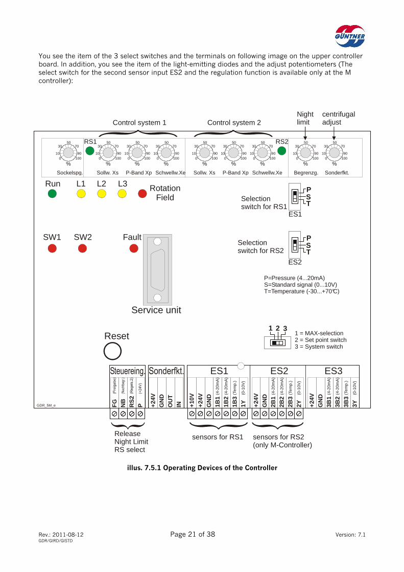
You see the item of the 3 select switches and the terminals on following image on the upper controller board. In addition, you see the item of the light-emitting diodes and the adjust potentiometers (The select switch for the second sensor input ES2 and the regulation function is available only at the M controller):
illus. 7.5.1 Operating Devices of the Controller
Sockelspg.
Service unit
ES1 ES2 ES3
RunSollw. Xs Sollw. Xs
RS1 RS2
P-Band Xp P-Band XpSchwellw.Xe Schwellw.Xe Begrenzg. Sonderfkt.
L1 L2 L3 RotationField
FaultSW1
%0 100
10 90
30 7050
%0 100
10 90
30 7050
%0 100
10 90
30 7050
%0 100
10 90
30 7050
10
%0 100
90
30 7050
%0 100
10 90
30 7050
%0 100
10 90
30 7050
%0 100
10 90
30 7050
%0 100
10 90
30 7050
Control system 1
Reset
SW2
GDR_5M_e FG
NB
RS
2P +2
4VG
ND
OU
TIN +1
0V+2
4VG
ND
+24V
GN
D
+24V
GN
D
PST
PST
3211 = MAX-selection2 = Set point switch3 = System switch
ES1
ES2
(4-2
0mA
)
(4-2
0mA
)
(Tem
p.)
(0-1
0V)
(4-2
0mA
)
(4-2
0mA
)
(Tem
p.)
(0-1
0V)
(4-2
0mA
)
(4-2
0mA
)
(Tem
p.)
(0-1
0V)
1B1
1B2
1B3
1Y 2B1
2B2
2B3
2Y 3B1
3B2
3B3
3Y
Control system 2
Selectionswitch for RS1
Selectionswitch for RS2
P=Pressure (4...20mA)S=Standard signal (0...10V)T=Temperature (-30...+70°C)
sensors for RS1 sensors for RS2(only M-Controller)
ReleaseNight LimitRS select
Nightlimit
centrifugaladjust
Rev.: 2011-08-12 Page 22 of 38 Version: 7.1 GDR/GIRD/GISTD
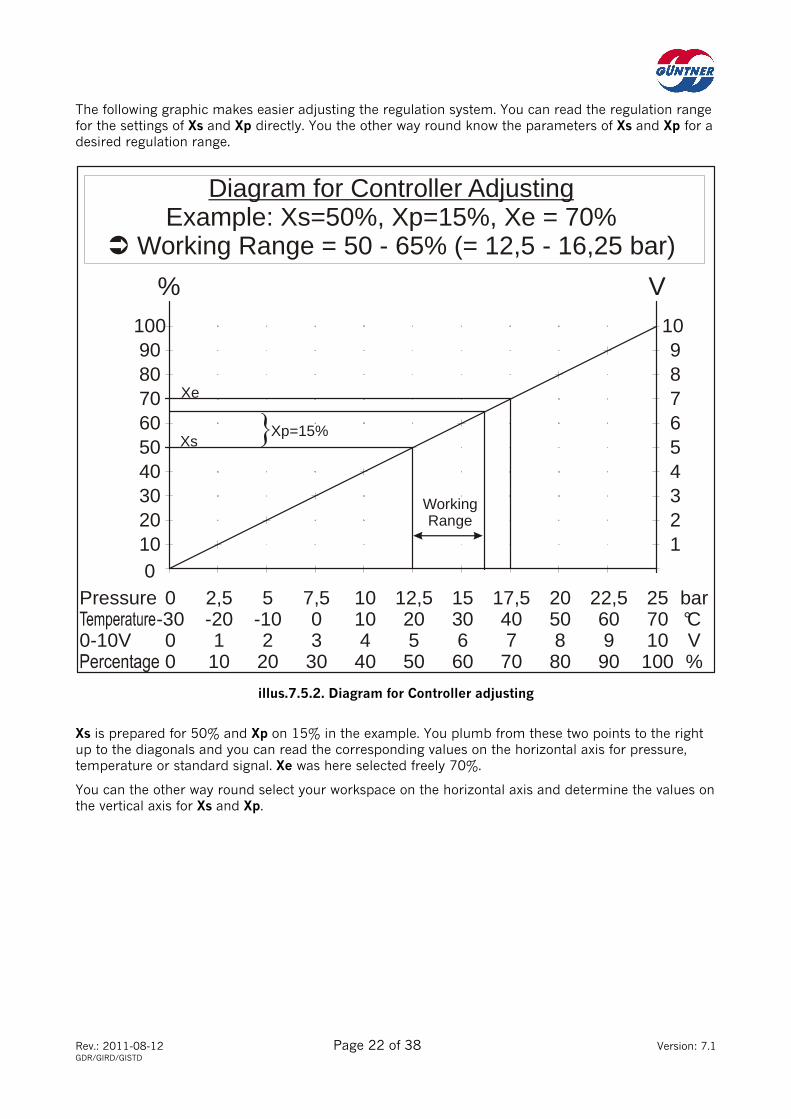
The following graphic makes easier adjusting the regulation system. You can read the regulation range for the settings of Xs and Xp directly. You the other way round know the parameters of Xs and Xp for a desired regulation range.
illus.7.5.2. Diagram for Controller adjusting
Xs is prepared for 50% and Xp on 15% in the example. You plumb from these two points to the right up to the diagonals and you can read the corresponding values on the horizontal axis for pressure, temperature or standard signal. Xe was here selected freely 70%.
You can the other way round select your workspace on the horizontal axis and determine the values on the vertical axis for Xs and Xp.
Diagram for Controller AdjustingExample: Xs=50%, Xp=15%, Xe = 70%
Working Range = 50 - 65% (= 12,5 - 16,25 bar)
Pressure
0-10V
0010 120 230 340 450 Xs 560 670 Xe
Xp=15%
WorkingRange
780 890 9
100 10
% V
-3000
2,5-201
10
5-10220
7,503
30
10104
40
12,520550
15306
60
17,5407
70
2050880
22,5609
90
25 bar70 °C10 V
100 %
Rev.: 2011-08-12 Page 23 of 38 Version: 7.1 GDR/GIRD/GISTD
7.6 Sensor connection
The U controller has one sensor input ES1, the M controller has two sensor inputs of ES1 and ES2. The signal of ES1 becomes RS1 passed on, the signal of ES2 to RS2, at regulation system.
Every sensor input is equipped with terminals for 1-2 pressure transmitter or 1 temperature probe or 1 standard signal.
Which sensor you connect at the signal input, must be adjusted with the corresponding select switch ES1 or ES2 as shown in chapter 7.5.
7.6.1 Sensor connection to regulation system 1 or 2 (Terminal ES1 or ES2)
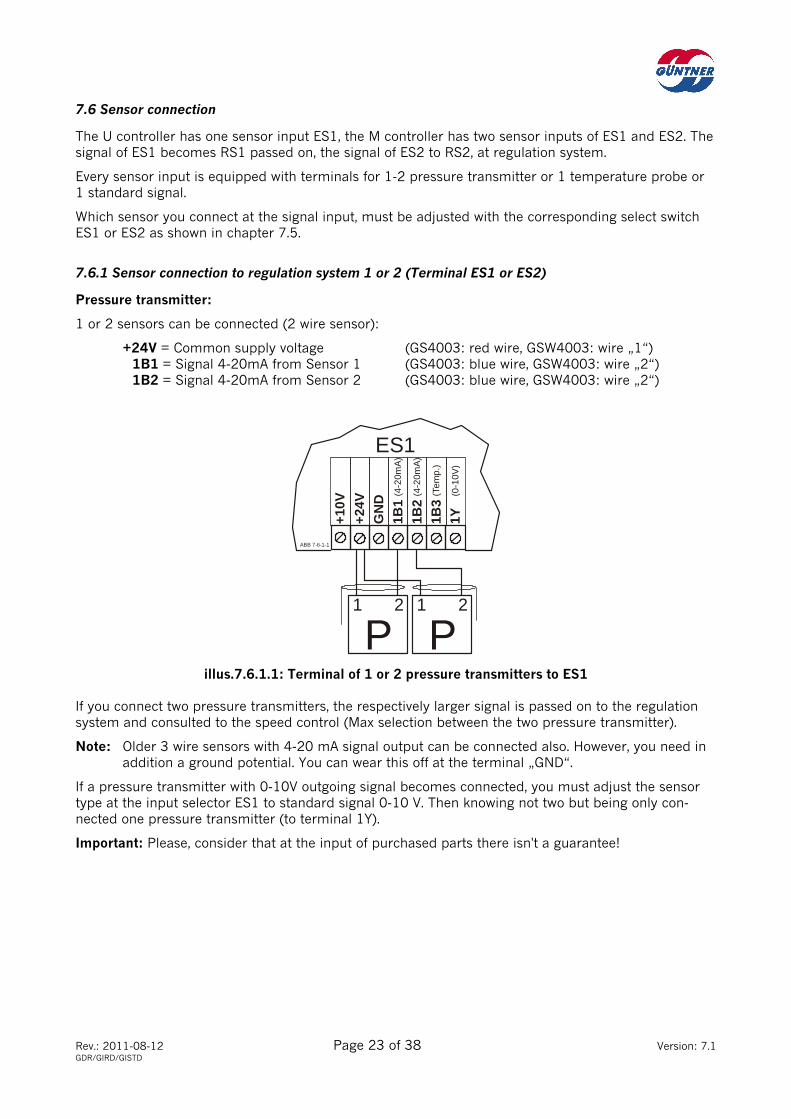
Pressure transmitter:
1 or 2 sensors can be connected (2 wire sensor):
+24V = Common supply voltage (GS4003: red wire, GSW4003: wire „1“) 1B1 = Signal 4-20mA from Sensor 1 (GS4003: blue wire, GSW4003: wire „2“) 1B2 = Signal 4-20mA from Sensor 2 (GS4003: blue wire, GSW4003: wire „2“)
illus.7.6.1.1: Terminal of 1 or 2 pressure transmitters to ES1
If you connect two pressure transmitters, the respectively larger signal is passed on to the regulation system and consulted to the speed control (Max selection between the two pressure transmitter).
Note: Older 3 wire sensors with 4-20 mA signal output can be connected also. However, you need in addition a ground potential. You can wear this off at the terminal „GND“.
If a pressure transmitter with 0-10V outgoing signal becomes connected, you must adjust the sensor type at the input selector ES1 to standard signal 0-10 V. Then knowing not two but being only con-nected one pressure transmitter (to terminal 1Y).
Important: Please, consider that at the input of purchased parts there isn't a guarantee!
ES1
ABB 7-6-1-1
+24V
+10V
GN
D (4-2
0mA
)
(4-2
0mA
)
(Tem
p.)
(0-1
0V)
1B1
1B2
1B3
1Y
P1 2 1 2
P
Rev.: 2011-08-12 Page 24 of 38 Version: 7.1 GDR/GIRD/GISTD
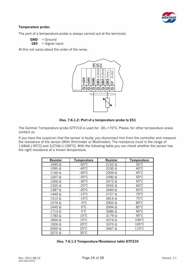
Temperature probe:
The port of a temperature probe is always carried out at the terminals
GND = Ground 1B3 = Signal input
At this not cares about the order of the wires.
illus. 7.6.1.2: Port of a temperature probe to ES1
The Güntner Temperature probe GTF210 is used for -30...+70°C. Please, for other temperature areas contact us.
If you have the suspicion that the sensor is faulty, you disconnect him from the controller and measure the resistance of the sensor (With Ohmmeter or Multimeter). The resistance must in the range of 1,04kΩ (-50°C) and 3,27kΩ (+100°C). With the following table you can check whether the sensor has the right resistance at a known temperature.
Resistor Temperature Resistor Temperature 1040 Ω -50°C 2152 Ω 35°C
1095 Ω -45°C 2230 Ω 40°C
1150 Ω -40°C 2309 Ω 45°C
1207 Ω -35°C 2390 Ω 50°C
1266 Ω -30°C 2472 Ω 55°C
1325 Ω -25°C 2555 Ω 60°C
1387 Ω -20°C 2640 Ω 65°C
1449 Ω -15°C 2727 Ω 70°C
1513 Ω -10°C 2814 Ω 75°C
1579 Ω -5°C 2903 Ω 80°C
1645 Ω 0°C 2994 Ω 85°C
1713 Ω 5°C 3086 Ω 90°C
1783 Ω 10°C 3179 Ω 95°C
1854 Ω 15°C 3274 Ω 100°C
1926 Ω 20°C 3370 Ω 105°C
2000 Ω 25°C 3467 Ω 110°C
2075 Ω 30°C
illus. 7.6.1.3 Temperature/Resistance table GTF210
ES1
ABB 7-6-1-2+2
4V+1
0V
GN
D (4-2
0mA
)
(4-2
0mA
)
(Tem
p.)
(0-1
0V)
1B1
1B2
1B3
1Y

Rev.: 2011-08-12 Page 25 of 38 Version: 7.1 GDR/GIRD/GISTD
Standard Signal 0-10V:
The port of a standard signal (0-10 V) is always carried out at the terminals
GND = Ground 1Y = Signal input 0-10V
Pay attention to the right polarity (Ground on GND, Signal on 1Y)!
illus. 7.6.1.4: Port of a standard signal or Handpoti GHP to ES1
You can connect a Güntner Handpoti GHP as far verse plate also as alternative. The terminals of the GHP are either with 1/2/3 or + -/ Y write:
+ or 3 to +24V - or 1 to GND Y or 2 to 1Y
The regulation system then has to be adjusted as follows:
Set point Xs = 0% (= 0V, On the left impact) P-Band Xp = 100% (=10V, On the right impact)
You then can use the speed controller as pure rotation speed calibration and provide the fan speed (or circuit stage number) manually.
This setting has to be carried out also at a house instrumentation and control mostly. (At this the mas-ter computer takes on the real closed-loop control and only the moving signal 0-10V submits for the fan speed to the speed controller.)
SLAVE-Mode:
If you use the controller as 'Slave' in a Master-Slave combination, are also these values to adjust (Xs=0%, Xp=100%).
7.6.2 Sensor connection to regulation system 2 (Terminal ES2) see chapter 7.6.1
ES1
ABB 7-6-1-4+2
4V+1
0V
GN
D (4-2
0mA
)
(4-2
0mA
)
(Tem
p.)
(0-1
0V)
1B1
1B2
1B3
1Y+ - Y3 1 2
Handpoti GHP
Standard Signal
- +0-10V
Rev.: 2011-08-12 Page 26 of 38 Version: 7.1 GDR/GIRD/GISTD
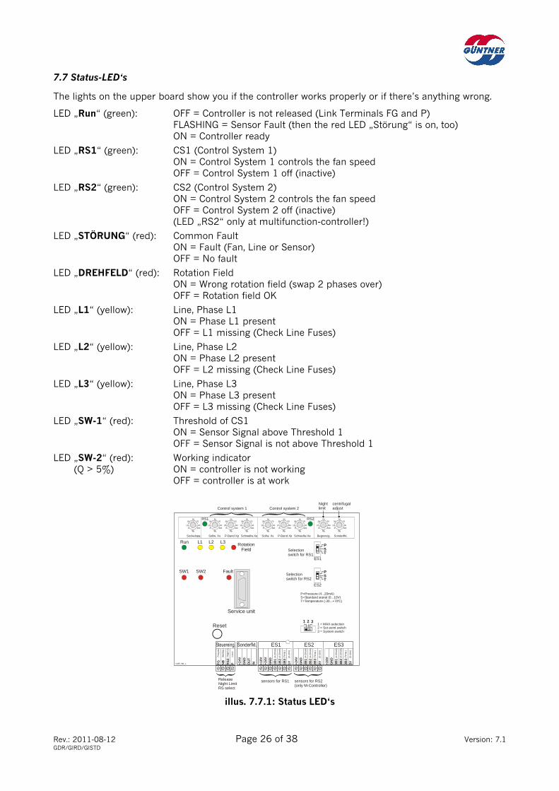
7.7 Status-LED‘s
The lights on the upper board show you if the controller works properly or if there’s anything wrong.
LED „Run“ (green): OFF = Controller is not released (Link Terminals FG and P) FLASHING = Sensor Fault (then the red LED „Störung“ is on, too) ON = Controller ready
LED „RS1“ (green): CS1 (Control System 1) ON = Control System 1 controls the fan speed OFF = Control System 1 off (inactive)
LED „RS2“ (green): CS2 (Control System 2) ON = Control System 2 controls the fan speed OFF = Control System 2 off (inactive) (LED „RS2“ only at multifunction-controller!)
LED „STÖRUNG“ (red): Common Fault ON = Fault (Fan, Line or Sensor) OFF = No fault
LED „DREHFELD“ (red): Rotation Field ON = Wrong rotation field (swap 2 phases over) OFF = Rotation field OK
LED „L1“ (yellow): Line, Phase L1 ON = Phase L1 present OFF = L1 missing (Check Line Fuses)
LED „L2“ (yellow): Line, Phase L2 ON = Phase L2 present OFF = L2 missing (Check Line Fuses)
LED „L3“ (yellow): Line, Phase L3 ON = Phase L3 present OFF = L3 missing (Check Line Fuses)
LED „SW-1“ (red): Threshold of CS1 ON = Sensor Signal above Threshold 1 OFF = Sensor Signal is not above Threshold 1
LED „SW-2“ (red): Working indicator (Q > 5%) ON = controller is not working OFF = controller is at work
illus. 7.7.1: Status LED‘s
Sockelspg.
Service unit
ES1 ES2 ES3
Run
Sollw. Xs Sollw. Xs
RS1 RS2
P-Band Xp P-Band XpSchwellw.Xe Schwellw.Xe Begrenzg. Sonderfkt.
L1 L2 L3 RotationField
FaultSW1
%0 100
10 90
30 7050
%0 100
10 90
30 7050
%0 100
10 90
30 7050
%0 100
10 90
30 7050
10
%0 100
90
30 7050
%0 100
10 90
30 7050
%0 100
10 90
30 7050
%0 100
10 90
30 7050
%0 100
10 90
30 7050
Control system 1
Reset
SW2
GDR_5M_e FG
NB
RS
2P +2
4VG
ND
OU
TIN +1
0V+2
4VG
ND
+24V
GN
D
+24V
GN
D
PST
PST
3211 = MAX-selection2 = Set point switch3 = System switch
ES1
ES2
(4-2
0m
A)
(4-2
0m
A)
(Te
mp
.)
(0-1
0V
)
(4-2
0m
A)
(4-2
0m
A)
(Te
mp
.)
(0-1
0V
)
(4-2
0m
A)
(4-2
0m
A)
(Te
mp
.)
(0-1
0V
)
1B1
1B2
1B3
1Y 2B1
2B2
2B3
2Y 3B1
3B2
3B3
3Y
Control system 2
Selectionswitch for RS1
Selectionswitch for RS2
P=Pressure (4...20mA)S=Standard signal (0...10V)T=Temperature (-30...+70°C)
sensors for RS1 sensors for RS2(only M-Controller)
ReleaseNight LimitRS select
Nightlimit
centrifugaladjust

Rev.: 2011-08-12 Page 27 of 38 Version: 7.1 GDR/GIRD/GISTD
7.8 Service device GSGM (Available as accessories)
The service device GSGM makes easier adjusting the controller and serves for the fault diagnosis. With this hand apparatus you can query the different adjust-potentiometer and the information about the current system parameters. The GSGM is usable for all microprocessor controlled speed controllers.
Connection to the controller:
The service device is connected to the 15pol. Sub D socket. This can be carried out also in the ongoing mode.
Adjust and queries of the mode parameters:
The controller only can be adjusted, if there isn't an interference. If e.g. the release is missing, the line rotating field is wrong or there is a motor fault, the controller is disabled and cannot be adjusted. The error is then displayed, e.g.: „Keine Freigabe!“, „Drucks. defekt!“ or „Motorstoerung!“. Eliminate the error in this case before you adjust the controller.
You find the following keys on the operating panel of the GSGM:
illus. 7.8.1: The operating panel of the GSGM
The keys are (of the left to the right): Up, Down, F1 (Function key) and Enter.
• Connect GSGM and wait for report „Guentner Elektro“. Pushing Reset briefly, if this doesn't appear after approx. 5 seconds. The standard display appears (Systemvalue and output „Q“).
• For adjusting the different parameter, press the button „UP“ or „DOWN“. The displayed parameter can adjusted with its potentiometer.
• You can by pushing the ENTER button to the standard display return any time.
• Plug remove - finished!
8. Special features (not in the standard equipment)
Added features are described on extra supplements. The following added features are offered:
• external set point specification
• outdoor temperature depending set point shifting
• outdoor temperature depending set point switching
• daylimit
• reversed characteristic (heating)
• full drive at sensor defect
Further added features can be made an enquiry about with us.
Rev.: 2011-08-12 Page 28 of 38 Version: 7.1 GDR/GIRD/GISTD
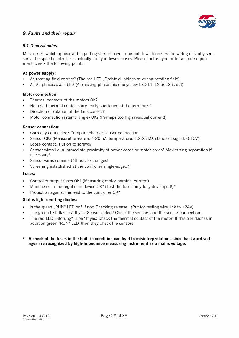
9. Faults and their repair
9.1 General notes
Most errors which appear at the getting started have to be put down to errors the wiring or faulty sen-sors. The speed controller is actually faulty in fewest cases. Please, before you order a spare equip-ment, check the following points:
Ac power supply:
• Ac rotating field correct? (The red LED „Drehfeld“ shines at wrong rotating field)
• All Ac phases available? (At missing phase this one yellow LED L1, L2 or L3 is out)
Motor connection:
• Thermal contacts of the motors OK?
• Not used thermal contacts are really shortened at the terminals?
• Direction of rotation of the fans correct?
• Motor connection (star/triangle) OK? (Perhaps too high residual current!)
Sensor connection:
• Correctly connected? Compare chapter sensor connection!
• Sensor OK? (Measure! pressure: 4-20mA, temperature: 1.2-2.7kΩ, standard signal: 0-10V)
• Loose contact? Put on to screws?
• Sensor wires lie in immediate proximity of power cords or motor cords? Maximising separation if necessary!
• Sensor wires screened? If not: Exchanges!
• Screening established at the controller single-edged?
Fuses:
• Controller output fuses OK? (Measuring motor nominal current)
• Main fuses in the regulation device OK? (Test the fuses only fully developed!)*
• Protection against the lead to the controller OK?
Status light-emitting diodes:
• Is the green „RUN“ LED on? If not: Checking release! (Put for testing wire link to +24V)
• The green LED flashes? If yes: Sensor defect! Check the sensors and the sensor connection.
• The red LED „Störung“ is on? If yes: Check the thermal contact of the motor! If this one flashes in addition green "RUN" LED, then they check the sensors.
* A check of the fuses in the built-in condition can lead to misinterpretations since backward volt-ages are recognized by high-impedance measuring instrument as a mains voltage.
Rev.: 2011-08-12 Page 29 of 38 Version: 7.1 GDR/GIRD/GISTD
10. Technical Data
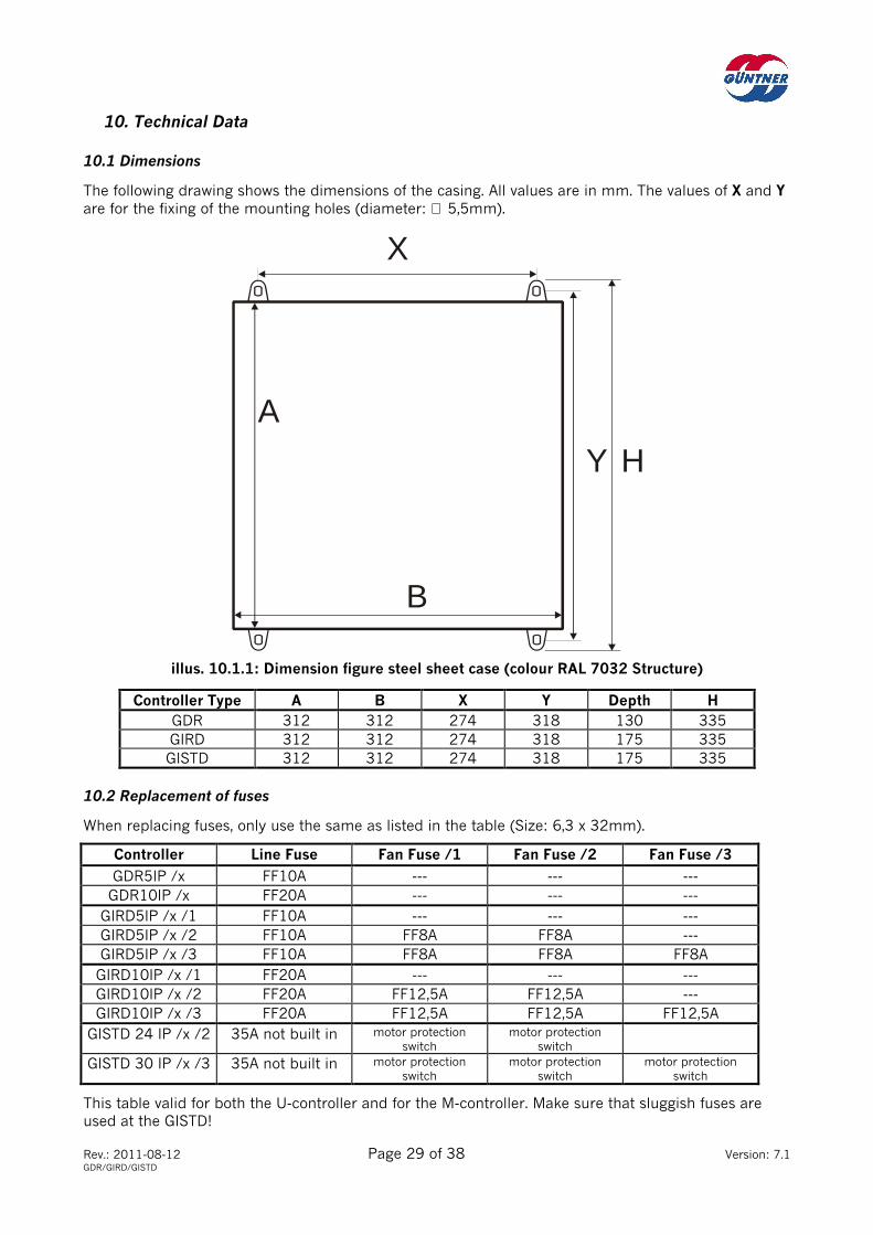
10.1 Dimensions
The following drawing shows the dimensions of the casing. All values are in mm. The values of X and Y are for the fixing of the mounting holes (diameter: ∅ 5,5mm).
illus. 10.1.1: Dimension figure steel sheet case (colour RAL 7032 Structure)
Controller Type A B X Y Depth H GDR 312 312 274 318 130 335
GIRD 312 312 274 318 175 335
GISTD 312 312 274 318 175 335
10.2 Replacement of fuses
When replacing fuses, only use the same as listed in the table (Size: 6,3 x 32mm).
Controller Line Fuse Fan Fuse /1 Fan Fuse /2 Fan Fuse /3
GDR5IP /x FF10A --- --- ---
GDR10IP /x FF20A --- --- ---
GIRD5IP /x /1 FF10A --- --- ---
GIRD5IP /x /2 FF10A FF8A FF8A ---
GIRD5IP /x /3 FF10A FF8A FF8A FF8A
GIRD10IP /x /1 FF20A --- --- ---
GIRD10IP /x /2 FF20A FF12,5A FF12,5A ---
GIRD10IP /x /3 FF20A FF12,5A FF12,5A FF12,5A
GISTD 24 IP /x /2 35A not built in motor protection switch
motor protection switch
GISTD 30 IP /x /3 35A not built in motor protection switch
motor protection switch
motor protection switch
This table valid for both the U-controller and for the M-controller. Make sure that sluggish fuses are used at the GISTD!
B
Y H
X
A
Rev.: 2011-08-12 Page 30 of 38 Version: 7.1 GDR/GIRD/GISTD
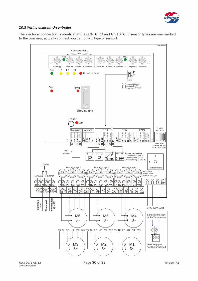
10.3 Wiring diagram U-controller
The electrical connection is identical at the GDR, GIRD and GISTD. All 3 sensor types are one marked to the overview, actually connect you can only 1 type of sensor!
Sockelspg.
Service unit
ES1 ES2 ES3
Run
LED
Sollw. Xs Sollw. Xs
RS1 RS2
P-Band Xp P-Band XpSchwellw.Xe Schwellw.Xe Begrenzg. Sonderfkt.
L1 L2 L3Rotation field
errorSW1
%0 100
10 90
30 7050
%0 100
10 90
30 7050
%0 100
10 90
30 7050
%0 100
10 90
30 7050
10
%0 100
90
30 7050
%0 100
10 90
30 7050
%0 100
10 90
30 7050
%0 100
10 90
30 7050
%0 100
10 90
30 7050
Control system 1
Reset
GDR5U004e
W4V4U4PE
W1V1U1PE
W5V5U5PE
W2V2U2PE
W6V6U6PE
W3V3U3PEPEL3L2L1
M43~
M53~
M63~
3Ph. 400V 50Hz
M13~
TK TK PE U1 V1 W1
M23~
TK TK PE U2 V2 W2
M33~
TK TK PE U3 V3 W3
FG
NB
RS
2P +2
4VG
ND
OU
TIN +1
0V+2
4VG
ND
1B1
1B2
1B3
1Y +24V
GN
D2B
12B
22B
32Y +2
4VG
ND
3B1
3B2
3B3
3Y
Com
mon
faul
t
Th
res h
old
Motor(group) 2Motor(group) 3 Motor(group) 1
Output fuseGIRD5: FF8AGIRD10: FF12,5A
Main switch
1
0
F2 F2 F2F3 F3 F3 F1 F1 F1
Main fuseGIRD5: FF10A
GIRD10: FF16A
3 x F0(6x32mm)
PST
ES1
(4-2
0mA
)
(4-2
0mA
)
(Tem
p.)
(0-1
0V)
(4-2
0mA
)
(4-2
0mA
)
(Tem
p.)
(0-1
0V)
(4-2
0mA
)
(4-2
0mA
)
(Tem
p.)
(0-1
0V)
P = Pressure (4-20mA)S = Standard (0-10V)T = Temperature (TF210)
ext.release
P1 2 1 2
P 0-10V
Sensor connection:1-2 Pressure tr. ( ) 1 Temp.-probe ( ) 1 Standard sig. 0-10V ( )
PT
S
oror
Series connectionof the TK terminals
free clamp pairmust be shortened!
12/22/32
11/21/31
14/24/34
PE PE22 32PE12
24 3421 311411
in o
pe r
atio
n
Q >
5%

Rev.: 2011-08-12 Page 31 of 38 Version: 7.1 GDR/GIRD/GISTD
10.4 Wiring diagram M-controller
The electrical connection is identical at the GDR and GIRD. The sensor connection for regulation sys-tem 1 to terminal ES1 is carried out exactly as when the U controller. Only the port therefore is shown to terminal ES2 for regulation system 2 here. With ES1 and ES2 you select the sensor type for each regulation system.
Sockelspg.
Service unit
ES1 ES2 ES3
Run
LED
Sollw. Xs Sollw. Xs
RS1 RS2
P-Band Xp P-Band XpSchwellw.Xe Schwellw.Xe Begrenzg. Sonderfkt.
L1 L2 L3Rotation field
ErrorSW1
%0 100
10 90
30 7050
%0 100
10 90
30 7050
%0 100
10 90
30 7050
%0 100
10 90
30 7050
10
%0 100
90
30 7050
%0 100
10 90
30 7050
%0 100
10 90
30 7050
%0 100
10 90
30 7050
%0 100
10 90
30 7050
Control system 1
Reset
SW2
GDR5M002e
W4V4U4PE
W1V1U1PE
W5V5U5PE
W2V2U2PE
W6V6U6PE
W3V3U3PEPEL3L2L1
M43~
M53~
M63~
3Ph. 400V 50Hz
M13~
TK TK PE U1 V1 W1
M23~
TK TK PE U2 V2 W2
M33~
TK TK PE U3 V3 W3
FG
NB
RS
2P +2
4VG
ND
OU
TIN +1
0V+2
4VG
ND
+24V
GN
D
+24V
GN
D
Motor(group) 2Motor(group) 3 Motor(group) 1 Main switch
1
0
F2 F2 F2F3 F3 F3 F1 F1 F1
Main fuseGIRD5: FF10AGIRD10: FF16A
3 x F0(6x32mm)
PST
PST
3211 = MAX-selection2 = Set point switch3 = System switch
P = Pressure (4-20mA)S = Standard (0-10V)T = Temperature (TF210)
ES1
ES2
(4-2
0mA
)
(4-2
0mA
)
(Tem
p.)
(0-1
0V)
(4-2
0mA
)
(4-2
0mA
)
(Tem
p.)
(0-1
0V)
(4-2
0mA
)
(4-2
0mA
)
(Tem
p.)
(0-1
0V)
1B1
1B2
1B3
1Y 2B1
2B2
2B3
2Y 3B1
3B2
3B3
3Y
Output fuseGIRD5: FF8AGIRD10: FF12,5A
ext.Release
Control system 2
P1 2 1 2
P 0-10V
Sensoranschluß:1-2 Pressure tr. ( ) 1 Temp.-probe ( )
1 Standard sig.0-10V ( )
Connection to ES1 is carried outexactly as when the U-controller, see there
PT
S
oror
!
Note:
Series connectionof the TK terminals
free clamp pairmust be shortened!
System 2
Com
mon
faul
t
Th
res h
old
12/22/32
11/21/31
14/24/34
PE PE22 32PE12
24 3421 311411
in o
pe r
atio
n
Q >
5%

Rev.: 2011-08-12 Page 32 of 38 Version: 7.1 GDR/GIRD/GISTD
10.5 Wiring diagram GISTD
The GISTD controller has the same connections as the GIRD or the GDR. Only there are no output fuses for the fans. The controller has a built in motor protection circuit..
W4V4U4PE
W1V1U1PE
W5V5U5PE
W2V2U2PE
W6V6U6PE
W3V3U3PEPEL3L2L1
M3~
M3~
M3~
M3~
TK TK PE U1 V1 W1
M3~
TK TK PE U2 V2 W2
M3~
TK TK PE U3 V3 W3
PE22PE12
24211411
1
0
12
11
14 22
21
24
GISTDM_e
ES1 ES2 ES3
Run
RS1 RS2
L1 L2 L3
%0 100
10 90
30 7050
%0 100
10 90
30 7050
%0 100
10 90
30 7050
%0 100
10 90
30 7050
10
%0 100
90
30 7050
%0 100
10 90
30 7050
%0 100
10 90
30 7050
%0 100
10 90
30 7050
%0 100
10 90
30 7050
Reset
FG
NB
RS
2P +2
4VG
ND
OU
TIN +
10V
+24
VG
ND
1B1
1B2
1B3
1Y +24
VG
ND
2B1
2B2
2B3
2Y +24
VG
ND
3B1
3B2
3B3
3Y
P
P
S
S
T
T
ES1
ES2
(4-2
0mA
)
(4-2
0mA
)
(Te
mp.
)
(0-1
0V)
(4-2
0mA
)
(4-2
0mA
)
(Te
mp.
)
(0-1
0V)
(4-2
0mA
)
(4-2
0mA
)
(Te
mp.
)
(0-1
0V)
P1 2 1 2
P 0-10V
Sensor connection:1-2 pressure transm. ( ) 1 Temp.-sensor ( ) 1 Standard signal. 0-10V ( )
PT
S
oror
1
0ES2 = same connections availiable
LINE3Ph. 400V 50Hz
Customer Supply(If No Factory Wiring)
4-Wire: Max.Cable Size = 2,5mm²
MainSwitch
NEUTRAL CHANGE OVERCONTACT MAX. 240V/1A
Fault: 11/12 closedNo Fault: 11/14 closed
Signal above Xe: 21/22 closedSignal below Xe: 21/24 closed
CommonFault
Relay 1(Threshold)
Manual
ServiceUnit
Set Point Xs Set Point XsP-Band Xp P-Band XpThreshld.Xe Threshold Xe Limitation Special
Rot. Field
FaultTH1
Control System 1 Control System 2
TH2P = Pressure (4-20mA)S = Standard (0-10V)T = Temperature (GTF210)
Selection ofsensor type
Fan(s) STEP 3 Fan(s) STEP 2 Fan(s) STEP 1
Ext. Release(Remove Link
if B.M.S. wired)
B.M.S.

Rev.: 2011-08-12 Page 33 of 38 Version: 7.1 GDR/GIRD/GISTD
10.6 Electrical and mechanical Data
Line voltage: 400V 50Hz
Motor nominal current: GDR/GIRD5: 05A (short-term +20% valid)
GDR/GIRD10: 10A (short-term +20% valid)
GISTD24: 24A
GISTD30: 30A
Dissipated heat: GDR/GIRD5 ca. 50W
GDR/GIRD10 ca. 90W
GISTD24/30 ca. 70W
Sensor connection: Pressure transmitter 4-20mA
or Temperature probe GTF210 (-30...+70°C)
or Standard signal 0-10V
Surroundings temperature: -20...+40°C
Deposit temperature: 0...+50°C
Weight: 9.5 kg max. without packing
Protection class: IP54
Dimensions: see table on page 29

Rev.: 2011-08-12 Page 34 of 38 Version: 7.1 GDR/GIRD/GISTD
Image directory
Page 4.2.1 AC LINE AND MOTOR CONNECTION................................................................................................................ 11
5.2.1 POTENTIAL-FREE REPORTING OUTPUTS....................................................................................................... 13
6.1.1 PORT OF THE EXTERNAL RELEASE CONTACT............................................................................................. 14
6.2.1 ACTIVATING THE FAN SPEED CLIPPING......................................................................................................... 14
6.3.1 CONNECTING CONTROLLER SWITCHOVER .................................................................................................. 14
7.5.1. OPERATING DEVICES OF THE CONTROLLER................................................................................................ 21
7.5.2. DIAGRAM FOR CONTROLLER ADJUSTING..................................................................................................... 22
7.6.1.1 TERMINAL OF 1 OR 2 PRESSURE TRANSMITTERS TO ES1 ................................................................... 23
7.6.1.2 PORT OF A TEMPERATURE PROBE TO ES1 .................................................................................................. 24
7.6.1.3 TEMPERATURE/RESISTANCE TABLE GTF210 ............................................................................................ 24
7.6.1.4 PORT OF A STANDARD SIGNAL OR HANDPOTI GHP TO ES1................................................................ 25
7.7.1 STATUS LED‘S............................................................................................................................................................ 26
7.8.1 THE OPERATING PANEL OF THE GSGM ......................................................................................................... 27
10.1.1 DIMENSION FIGURE STEEL SHEET CASE....................................................................................................... 29
10.3 WIRING DIAGRAM U-CONTROLLER GDR/GIRD ........................................................................................... 30
10.4 WIRING DIAGRAM M-CONTROLLER GDR/GIRD........................................................................................... 31
10.5 WIRING DIAGRAM M-CONTROLLER GISTD.................................................................................................... 32

Rev.: 2011-08-12 Page 35 of 38 Version: 7.1 GDR/GIRD/GISTD
INDEX
3
3 wire sensors ___________________________ 23
A
AC power supply_________________________ 10
B
Bypass wiring ___________________________ 17
C
Cable inlets _______________________________9 Centrifugal drives ________________________ 18 Classification ______________________________5 Clipping_________________________________ 17 Common fault ___________________________ 13 Connection wires ________________________ 10 Control inputs ___________________________ 14 Controller functions ______________________ 19
D
Day/night switchover_____________________ 20 Diagram Controller Adjusting _____________ 22 Diagram of the adjust potentiometer ______ 21 Dimensions _____________________________ 29
E
Error Fuses______________________________ 28 External static pressure___________________ 19
F
Fan mode report_________________________ 17 Faults___________________________________ 28 Faults -General notes- ____________________ 28 Features of the controller _________________ 33 fuses ___________________________________ 29 Fuses ___________________________________ 10
G
GISTD Threshold level ____________________ 37 GISTD wiring ____________________________ 32 GSGM __________________________________ 27 GSW4003 _______________________________ 23 GTF210 _________________________________ 24
H
Handpoti GHP ___________________________ 25 Humidity protection_____________________ 2, 9
I
Image directory __________________________ 34 Interference Ac power supply ______________ 28 Interference motor connection _____________ 28 Interference sensor connection ____________ 28
L
LED Drehfeld_____________________________ 26 LED Fault ________________________________ 26 LED L1 __________________________________ 26 LED L2 __________________________________ 26 LED L3 __________________________________ 26 LED Rotation Field________________________ 26 LED RS1_________________________________ 26 LED RS2_________________________________ 26 LED Run _________________________________ 26 LED Störung _____________________________ 26 LED SW-1________________________________ 26 LED SW-2________________________________ 26 LED Threshold ___________________________ 26
M
Manual Button (Sockelspannung) __________ 18 Manual Mode ____________________________ 18 MAX-Selection____________________________ 20 M-controller______________________________ 31 Minimum voltage_________________________ 18 Motor connection_________________________ 11 Mounting _________________________________ 9 Multifunction_____________________________ 15
N
Night Limit NB ___________________________ 17
O
Operating panel GSGM____________________ 27
P
P-Band Xp _______________________________ 16 Pressure transmitter __________________ 15, 23 Primer____________________________________ 6 Primer Adjusting the controller _____________ 7
R
Release__________________________________ 14 Replacement of fuses _____________________ 29 Reporting outputs ________________________ 13 RESET nonlocking key ____________________ 14 RS2 _____________________________________ 20

Rev.: 2011-08-12 Page 36 of 38 Version: 7.1 GDR/GIRD/GISTD
S
Selection of the controller function ________ 19 Sensor connection _______________________ 23 Sensor connection ES2 ___________________ 25 Sensor defect____________________________ 13 Sensors (3-wire) _________________________ 23 Service device ___________________________ 27 Set point switch__________________________ 19 Set point Xs _____________________________ 15 Slave Mode______________________________ 25 Special features _________________________ 27 Standard signal__________________________ 15 Standard signal 0-10V ___________________ 25 Status LED‘s_____________________________ 26 Status LED’s indicate errors_______________ 28 Summer/winter switchover _______________ 20 Switchover to RS2 _______________________ 14 System switch ___________________________ 20
T
Table to the fault diagnosis _______________ 38 Technical Data________________________ 29, 33 Temperature probe ______________________ 24 Temperature probe ______________________ 15
Temperature/Resistance table GTD210_____ 24 Test mode _______________________________ 18 Thermal contact__________________________ 11 Threshold value __________________________ 13 Threshold value Xe _______________________ 17 TK ______________________________________ 11
U
U-controller ______________________________ 30 Unifunction ______________________________ 15
V
Ventilation ________________________________ 9
W
Wedge belt-drive _________________________ 18 Weighted noise filter ______________________ 12 Workspace of the controller _______________ 16
X
Xe_______________________________________ 17 Xp ______________________________________ 16 Xs_______________________________________ 15

Rev.: 2011-08-12 Page 37 of 38 Version: 7.1 GDR/GIRD/GISTD
GISTD Threshold level
Step On Off
1 40% 5% GISTD 24 /IP 2 M
2 80% 40%
1 33% 23%
2 66% 56%
GISTD 30 /IP 3 M
3 90% 80%
Revision: 7.1 Chapter 6.4 Controller blocking by motor fault corrected.
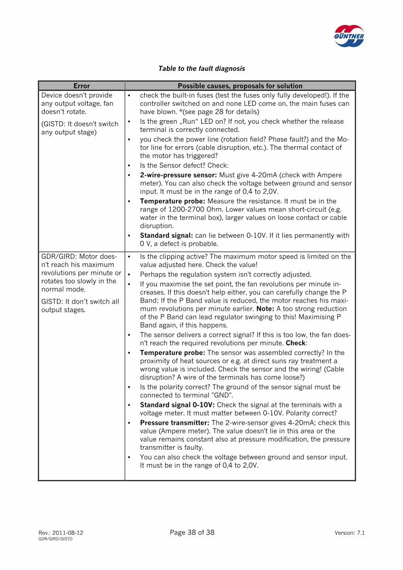
Rev.: 2011-08-12 Page 38 of 38 Version: 7.1 GDR/GIRD/GISTD
Table to the fault diagnosis
Error Possible causes, proposals for solution Device doesn't provide any output voltage, fan doesn’t rotate.
(GISTD: It doesn't switch any output stage)
• check the built-in fuses (test the fuses only fully developed!). If the controller switched on and none LED come on, the main fuses can have blown. *(see page 28 for details)
• Is the green „Run“ LED on? If not, you check whether the release terminal is correctly connected.
• you check the power line (rotation field? Phase fault?) and the Mo-tor line for errors (cable disruption, etc.). The thermal contact of the motor has triggered?
• Is the Sensor defect? Check:
• 2-wire-pressure sensor: Must give 4-20mA (check with Ampere meter). You can also check the voltage between ground and sensor input. It must be in the range of 0,4 to 2,0V.
• Temperature probe: Measure the resistance. It must be in the range of 1200-2700 Ohm. Lower values mean short-circuit (e.g. water in the terminal box), larger values on loose contact or cable disruption.
• Standard signal: can lie between 0-10V. If it lies permanently with 0 V, a defect is probable.
GDR/GIRD: Motor does-n't reach his maximum revolutions per minute or rotates too slowly in the normal mode.
GISTD: It don’t switch all output stages.
• Is the clipping active? The maximum motor speed is limited on the value adjusted here. Check the value!
• Perhaps the regulation system isn't correctly adjusted.
• If you maximise the set point, the fan revolutions per minute in-creases. If this doesn't help either, you can carefully change the P Band: If the P Band value is reduced, the motor reaches his maxi-mum revolutions per minute earlier. Note: A too strong reduction of the P Band can lead regulator swinging to this! Maximising P Band again, if this happens.
• The sensor delivers a correct signal? If this is too low, the fan does-n't reach the required revolutions per minute. Check:
• Temperature probe: The sensor was assembled correctly? In the proximity of heat sources or e.g. at direct suns ray treatment a wrong value is included. Check the sensor and the wiring! (Cable disruption? A wire of the terminals has come loose?)
• Is the polarity correct? The ground of the sensor signal must be connected to terminal "GND".
• Standard signal 0-10V: Check the signal at the terminals with a voltage meter. It must matter between 0-10V. Polarity correct?
• Pressure transmitter: The 2-wire-sensor gives 4-20mA; check this value (Ampere meter). The value doesn't lie in this area or the value remains constant also at pressure modification, the pressure transmitter is faulty.
• You can also check the voltage between ground and sensor input. It must be in the range of 0,4 to 2,0V.