manual distance measurement series...
TRANSCRIPT

MANUAL
FACTORY AUTOMATION
Distance Measurement SeriesVDM100
INTERBUSSYNCHRON SERIELLES INTER FACE
R

Dat
e of
issu
e09
/21/
2010
Par
t No.
206
909
With regard to the supply of products, the current issue of the following document is applicable:
The General Terms of Delivery for Products and Services of the Electrical Industry, published by the Central Association of the Electrical Industry (Zentralverband Elektrotechnik und Elektroindustrie (ZVEI) e.V.)
in its most recent version as well as the supplementary clause: "Expanded reservation of proprietorship"

Distance measurement device VDM100
Dat
e of
issu
e09
/21/
2010
Par
t No.
206
909
3
1 Introduction ............................................................................... 41.1 Guarantee ........................................................................................ 4
2 Declaration of Conformity ........................................................ 5
3 Safety .......................................................................................... 63.1 Symbols used ................................................................................... 63.2 General safety instructions ............................................................... 63.3 Proper use ........................................................................................ 7
4 Product description ..................................................................... 74.1 Displays and controls ....................................................................... 84.2 Scope of delivery: ............................................................................. 94.3 Accessories ...................................................................................... 9
5 Installation ................................................................................. 105.1 Storage and Transport ................................................................... 105.2 Unpacking ...................................................................................... 105.3 Mounting ........................................................................................ 105.4 Reflector selection .......................................................................... 125.5 Reflector arrangement ................................................................... 13
6 Commissioning ......................................................................... 136.1 Connecting the Device ................................................................... 146.2 Grounding / Shielding ..................................................................... 156.3 Adjustment ..................................................................................... 156.4 Display indication ........................................................................... 16
7 Settings ..................................................................................... 177.1 Menu Structure ............................................................................... 177.2 Description of menu items .............................................................. 187.3 Operation ....................................................................................... 227.4 FAQ ................................................................................................ 23
8 Maintenance and Repair ........................................................... 23
9 Fault elimination ........................................................................ 24
10 Appendix .................................................................................. 2510.1 Technical data .............................................................................. 2510.2 Model numbers .............................................................................. 2810.3 Description of Interfaces ................................................................ 2910.4 Information on the GSD file (PROFIBUS DP) ................................ 32

Distance measurement device VDM100Introduction
Issu
e da
te21
.09.
2010
Par
t no.
206
909
1 Introduction
Sincere congratulationsYou have chosen a device from Pepperl+Fuchs. Pepperl+Fuchs develops, produces and markets electronic sensors and interface modules worldwide for the automation technol-ogy market.ContactIf you have any questions about the device, its functions, or accessories, please contact us at:Pepperl+Fuchs GmbHLilienthalstrasse 200D-68307 MannheimTelephone: 0621 776-1111Fax: 0621 776-271111E-mail: [email protected]
1.1 Guarantee
Pepperl+Fuchs manufactures its hardware products according to recognized industrial standards. Pepperl+Fuchs guarantees its products to be free of defects in material and workmanship provided the products are used under the normal operating conditions specified by the manufacturer. The warranty applies only to the original owner and is not transferable. All accompanying exclusions of liability, restrictions, and other conditions of this section apply to this warranty.Exclusions of liabilityNo warranty obtained or granted hereby shall apply to products that:• have been repaired, modified, or tampered with unless explicitly performed or ap-
proved by Pepperl+Fuchs,• have not been serviced in accordance with the Operating and Handling Instructions
provided by Pepperl+Fuchs,• have been exposed to unusual physical or electrical loads, immersed in liquids, or ex-
posed to any one of the following circumstances:• breakdown,• crushing,• improper use,• misuse,• low current,• unsuitable power supply• reverse polarity,• negligence or accident,
• or has been used for any purpose other than what is described in the Operating and Handling Instructions.
Preventive maintenance is the customer's responsibility and is not covered by this war-ranty.
4

Distance measurement device VDM100Declaration of Conformity
Issu
e da
te21
.09.
2010
Par
t no.
206
909
GeneralWith the exception of the warranties noted above, Pepperl+Fuchs offers no warranties for products delivered below in any form whatsoever, whether explicit or implicit, includ-ing but not limited to implicit defect warranty services and guarantee of suitability for a specific purpose, and absence of injury. The explicit warranties noted above shall satisfy all obligations and liabilities of Pepperl+Fuchs for damages, including but not limited to concrete damages, indirect damages or consequential damages in connection with the use or design of the product. The seller's liability to the buyer and other persons (regard-less of the origin of liability, whether it be based on contract, warranty, impermissible han-dling, misuse, and/or other origin) in connection with the use of a product shall in no case exceed the original purchase price of the product. Pepperl+Fuchs shall in no event be liable for consequential damages, concrete and indirect damages, secondary damages or penalties, or lost profits, sales, or loss of data, even if Pepperl+Fuchs had been made aware of this possibility.
2 Declaration of Conformity
We, Pepperl+Fuchs GmbH, hereby declare that the
Distance Measurement Device VDM100
and all models of this product to which this declaration refers are in conformity with the following standards and other regulatory documents
EN 61326-1:2006, EN60947-5-2:2007
Product family standard: Electromagnetic Compatibility (EMC for light industry and in-dustry)
Pepperl+Fuchs GmbH in D-68301 Mannheim has a certified quality assurance system in conformity with ISO 9001.
The laser distance measurement device VDM100 was designed exclu-sively for use in industrial environments.The device may cause radio interference if used in a domestic environ-ment.
A corresponding Declaration of Conformity may be requested from the manufacturer.
ISO9001
5

Distance measurement device VDM100Safety
Issu
e da
te21
.09.
2010
Par
t no.
206
909
3 Safety
3.1 Symbols used
Safety-related symbols
Informative symbols
3.2 General safety instructions
The following basic instructions must be observed in all cases:• The device must not be commissioned until the manual has been read and understood• The power supply that generates the supply voltage must be reliably
insulated electrically with double insulation and a safety transformer according to DIN VDE 0551 (corresponds to IEC 742).
• The device must not be used out of specification without suitable protective measures• No unauthorized tampering with the device is permitted• Do not point the device directly at the sun or measure into the sun• Do not remove the warning instructions or rating platesThe radiation emitted by a Class 1 laser is harmless. This type of laser instrument can be operated by anyone.The system operator is responsible for planning, mounting, commissioning, operation, and maintenance of the system.
Installation and commissioning of all devices must only be performed by personnel spe-cially trained for that purpose.
Danger!This symbol identifies an immediate and present danger.Failure to observe this warning may result in personal injury or even death.
Warning!This symbol warns of a possible malfunction or hazard.Failure to observe this warning may result in personal injury or exten-sive damage to property.
Caution!This symbol warns of a possible malfunction.If the instruction given in this warning is not heeded, the device and any plant or systems connected to it could develop a fault or fail completely.
Note!This symbol draws your attention to important information.
Handling instructionsThis symbol marks instructions for action.
6

Distance measurement device VDM100Product description
Issu
e da
te21
.09.
2010
Par
t no.
206
909
The protection of the system and operating personnel is not ensured if the module is not used according to its intended purpose.
Observe the applicable laws and regulations for use and for the intended purpose. The devices are only approved for proper use in accordance with the intended purpose. Any other use voids all warranty claims and manufacturer's responsibility.Use only recommended original accessories.If you are unable to eliminate malfunctions, take the device out of operation. Secure the device against accidental operation. Return the device to Pepperl+Fuchs for repair. In-terventions and modifications are potentially hazardous, and any warranty and manufac-turer's liability shall become void.
Dispose of unusable devices in keeping with the applicable national legal regulations.For example, you can take the sensor to the designated collection point for electronic scrap.
3.3 Proper use
Series VDM 100 distance measurement devices are used to determine the exact posi-tioning of stock feeders, moving shuttles, cranes, and automatic handling equipment and for distance measurements in the woodworking industry, on concrete saws, and in ele-vator construction. It must be ensured that the devices are only used in accordance with their intended and designated purpose.
4 Product description
VDM100Exact positioning of stock feeders, moving shuttles, cranes, and automatic handling equipment, as well as distance measurements in the woodworking industry, on concrete saws, and in elevator construction requires distance measurement devices capable of re-turning measurement values at a high measurement rate over great distances with milli-meter precision.Distance measurement devices are used wherever distances were previously measured by shaft encoders or electromechanical measurement means. By their very nature, those mechanical measurement value generators are highly susceptible to changes in ambient conditions, for example temperature, and are also subject to aging and constant wear.Photoelectric distance measurement devices are practically wear-free in operation and are easy to install with a built-in laser pointer.Other advantages include short assembly and commissioning times, the high level of re-liability offered by a photoelectric measurement system, and the ease of replacement.The VDM series covers three standard distance ranges: 50 m, 150 m and 300 m.Available interfaces include:• SSI (Synchronous Serial Interface),• INTERBUS,• PROFIBUS DP
In applications with high storage racks and moving shuttles, care must always be taken to observe the applicable safety regulations. Failure to do so may result in serious or fatal injury!
7

Distance measurement device VDM100Product description
Issu
e da
te21
.09.
2010
Par
t no.
206
909
Series VDM100 photoelectric distance measurement devices meet the safety require-ments of laser protection class 1 (EN 60825) in measurement mode. The low level of emitted laser light ensures that operating personnel will not be injured or suffer any ad-verse health effects.Measuring principle The device works according to the principle of Pulse Ranging Technology (PRT). The time between when an invisible light pulse is emitted and when the reflected pulse is re-ceived is measured in the device. Since the speed of light is constant, this time serves as a measure of distance. The light source and receiver are both located in the device. A reflector is required for the distance measurement. It must be installed opposite the de-vice. Because of its technical characteristics, the Pulse Ranging Technology (PRT) is es-pecially suitable for highly accurate distance measurement over great distance compared to other methods. In comparison to other methods of distance measurement, a time-of-flight measurement is largely independent of the measurement environment and can therefore also be used in harsh everyday industrial settings with a high level of accuracy.
4.1 Displays and controls
Figure 4.1: Displays and controls
Table 4.2: Displays and controls
Effects of ambient conditions:The speed of the propagation of light is independent of air temperatureand pressure.The effect of air temperature is 1 ppm/KThe effect of air pressure is -0.3 ppm/hPaThese errors must be taken into consideration by the user for long dis-tances.For example, in the working range of the VDM (-10 °C ... +50 °C) the error at a distance of 100 m is 6 mm.
No. Name Color No. Name Color
1 Power LED Green 4 ERROR LED Red
2 Display 5 BUS LED Green
3 TARGET LED Green 6 Operating keys
1 2 3 4 5 6
PWR TGT ERR BUS
8

Distance measurement device VDM100Product description
Issu
e da
te21
.09.
2010
Par
t no.
206
909
4.2 Scope of delivery:
The delivery package contains:• VDM100• Manual• Functional grounding (pre-mounted)• Protective cap LS610
4.3 Accessories
The following products are available as accessories:
No. Name Figure Description
1 OMH-VDM100-01Mounting bracket with deviation mirror
2 OMH-LS610-01 Mounting bracket
3 OMH-LS610-02Direct installation set(4 threaded inserts M4)
4 OMH-LS610-04 Hood
5 Functional grounding LS610 Functional grounding
6 Protective cap LS610 M12 locking caps
7 ICZ-TR-V15B PROFIBUS terminal resistor
8 Reflektor VDM01 Plastic reflector 500 mm x 500 mm
9Reflektor VDM02only in connection with the Reflector VDM01
Plastic reflector 500 mm x 250 mm
10 Reflector 250 mm x 250 mm Foil reflector 250 mm x 250 mm
11 Reflector 500 mm x 500 mm Foil reflector 500 mm x 500 mm
12 Reflector 1000 mm x 1000 mm Foil reflector 1000 mm x 1000 mm
9

Distance measurement device VDM100Installation
Issu
e da
te21
.09.
2010
Par
t no.
206
909
Table 4.3: Accessories
5 Installation
5.1 Storage and Transport
Pack the device so it is protected against impacts during storage and transport and pro-tect it against humidity. The original packaging offers optimum protection. Note also the admissible ambient conditions.
5.2 Unpacking
Make certain the contents are not damaged. If damage has occurred, please contact the mail or shipping service and inform the supplier.-Check the delivery, comparing your order with the delivery papers.Save the original packaging in case the device needs to be placed in storage or shipped some time in the future.If you have any questions, please contact Pepperl+Fuchs.
5.3 Mounting
If existing adjustment and mounting options are to be used, M4 inserts can be pressed into the enclosure foot fixtures; to be ordered as an accessory (Page 9) Pos. 2.The accessory OMH-LS610-01, a mounting bracket for attachment to walls, permits fast installation and adjustment.
13 V15SB-GConnector, M12 x 1, B coded, 5-pin for bus cable
14 V15B-G Connector, M12 x 1, B coded, 5-pin for bus cable
15 V1-GConnector, M12 x 1, 4-pin for power supply
If the temperature is subject to major fluctuations during transport, an acclimatization time of about 2 hours must be allowed before the device is installed and used. Always avoid condensation within the device, since this could adversely affect the internal parts or even destroy them.
Do not aim the sensor at the sun. Protect the sensor from direct long-term exposure to sun. Prevent condensation from forming by not expos-ing the sensor to any major fluctuations in temperature. Do not expose the sensor to the effects of any aggressive chemicals. Keep the lenses and reflector of the device clean. Clean with a soft cloth, using standard commercial glass cleaner if necessary.
10
Distance measurement device VDM100Installation
Issu
e da
te21
.09.
2010
Par
t no.
206
909
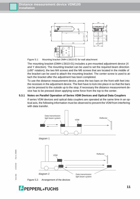
Figure 5.1: Mounting bracket OMH-LS610-01 for wall attachment
The mounting bracket (OMH-LS610-01) includes a pre-mounted adjustment device (X and Y direction). The mounting bracket can be used to set the required beam direction (±90° rotation); the two M4 screws and the M6 screws that are located in the middle of the bracket can be used to attach the mounting bracket. The center screw is used to at-tach the bracket after the adjustment has been completed.To use the distance measurement device, press the two bars on the front with feet into the recesses in the adjustment device. The feet have to lock into place in so that the bars can be pressed to the outside up to the stop; if necessary the distance measurement de-vice has to be pressed down applying some force from the top to the center.
5.3.1 Notes on Parallel Operation of Series VDM Devices and Optical Data Couplers
If series VDM devices and optical data couplers are operated at the same time in an op-tical axis, the following information must be observed to prevent the VDM from interfering with data transfer.
Figure 5.2: Arrangement of the devices
max
. 153
ø 8.5
80
4426
200
100
100266
10
40 ..
. 53
diagram 1
diagram 2
VDM
VDM
Data transmissionlight beam system
Reflector
Data transmissionlight beam system
Reflector
11

Distance measurement device VDM100Installation
Issu
e da
te21
.09.
2010
Par
t no.
206
909
1. Normally we recommend an arrangement as shown in Figure 5.2 (1). Data transfer and distance measurement take place on two different sides of the vehicle. Take care to ensure the optical data coupler on the left side of the screen is not receiving any scattered light from the VDM. In most cases this presents no problem, since the vehicle blocks scattered light. This arrangement of devices is preferred for that rea-son.
2. If data transfer and distance measurement both take place on one side of the vehicle as shown in (2), the distance measurement may interfere with the data transfer if there is not enough space on the side. This happens because the foil reflector re-flects the sharply focused beam of light under a larger dispersion angle and some of the reflected light makes its way into the receiving lens of the optical data coupler.
We therefore recommend always using a plastic reflector with low dispersion for this arrangement.
How much space is needed on the side between the optical data coupler and distance measurement device depends on the sensing range.
Table 5.3: Relationship between distance and distance a
If the optical data coupler and distance measurement device are arranged as shown in (2), make certain that the beam of light from the VDM does not fall directly on the optical data coupler across from it.
5.4 Reflector selection
Table 5.4: Reflector selection
The reflector VDM02 can only be used in conjunction with the reflector VDM01. The re-flector VDM02 can be used as an extension to the VDM01. It serves only to intercept a possible migration of the measuring mark by means of unevenness or vibrations.
Distance Distance a
30 m 0.5 m
60 m 0.8 m
90 m 1.0 m
120 m 1.2 m
240 m 2.4 m
300 m 3.2 m
Reflector250 x 250
Reflector500 x 500
Reflector1000 x 1000
ReflectorVDM01
(500 mm x 500 mm)
ReflectorVDM02
(500 mm x 250 mm)
VDM100-50 Yes Yes Yes Yes Yes
VDM100-150 No Yes, if VDM is stable
Yes Yes Yes
VDM100-300 No No No Yes Yes
12

Distance measurement device VDM100Commissioning
Issu
e da
te21
.09.
2010
Par
t no.
206
909
13
5.5 Reflector arrangement
Figure 5.5: General reflector arrangement (side view of VDM)
Figure 5.6: Foil reflector arrangement (top view of VDM)
Figure 5.7: 3D view orientation of sensor alignment and required inclination of reflector
6 Commissioning
After the device is turned on, it enters an initialization phase of about 10 seconds. The red front LED (ERR) goes out as soon as the VDM100 has been correctly aligned to the reflector. The VDM100 is then ready for operation.To achieve the best accuracy, allow a warm-up phase of 10 minutes.The sensor has been tested and calibrated before delivery. It can be placed in operation immediately.
Beam diameter: appr. 15 cm appr. 25 cm appr. 35 cm appr. 65 cm
0 100 m 150 m 300 m50 m
Foil reflector
2° ± 0,5°
1,5°... 2,5°

Distance measurement device VDM100Commissioning
Issu
e da
te21
.09.
2010
Par
t no.
206
909
6.1 Connecting the Device
In order to ensure IP65 protection degree, the unused M12 connectors have to be fitted with protective caps, which can be ordered as accessories.(See Chapter 4.3)The device is in conformity with protection class III. Please observe that the power supply has to be ensured by power packs, which supply low protective voltage (PELV). The grounding of the cable screens on the metal plug-in connectors in not a protective grounding suitable for protection of persons. It is simply a functional grounding (See Chapter 6.2). The power supply of the VDM100 is direct current 18 V - 30 V DC.The VDM100 has two I/O connections that can be configured separately as an input or output. (See “I/O1 and I/O2” on page 19.). For inputs, an electrical level of Ue < 6 V is considered ‘low’ and a level of Ue > 16 V ‘high’. A connection configured as an output has a ‘low’ electrical level of Ua < 1 V and a ‘high’ level of Ua = UB - 1 V at a maximum load of 200 mA, whereby UB represents the supply voltage connected to the device. Both I/Os can be configured as a high active or a low active connection. The maximum cable length are 30 m.The pin assignment of the plugs is as follows:VDM100-SSI:
Figure 6.1: SSI interface pin assignment
VDM100-P:
Figure 6.2: PROFIBUS DP interface pin assignment
4
1
2
3
24 V DC
0 V
4
1
2
3
5
D+
CLK+
D-
CLK-
PowerServiceSSI
I/O 1
I/O 2
Shield
12
43
5
12
43
Shield
4
1
2
3
24 V DC
0 V
4
1
2
3
5
n.c.
n.c.
Rx/Tx-N
Rx/Tx-P
PowerServiceBus IN
I/O 1
I/O 2
Shield
Shield
4
1
2
3
5
VP
DGND
Rx/Tx-N
Rx/Tx-P
Bus Out/Termination
Shield
Shield
21
34
5
12
43
5
12
43
14

Distance measurement device VDM100Commissioning
Issu
e da
te21
.09.
2010
Par
t no.
206
909
VDM100-IBS:
Figure 6.3: INTERBUS interface pin assignment
6.2 Grounding / Shielding
Functional grounding of the shields is recommended, since the housing does not allow for any grounding. If the shields need to be grounded for reasons related to EMC, Section 3.3.3 of the PROFIBUS PNO manual and the "Conformance test and certification V2.0" of the INTERBUS Club must be observed.Please use the pre-mounted socket tongue for the screen grounding. The socket tongue is screwed to the bus link. The primary fastening nut of the plug-in connector must never be opened. If it is, the connecting assembly may be damaged and the housing may be-come leaky. The functional grounding can also be ordered as accessories. (see Chapter 4.3)
Figure 6.4: pre-mounted socket tongue
6.3 Adjustment
A clearly visible alignment laser pointer is located on the front of the device to assist with alignment. Using the alignment laser pointer, the distance measurement device can be optimally aligned to the reflector.
Figure 6.5: Alignment aid
4
1
2
3
24 V DC
0 V
4
1
2
3
5
DO1
DI1
/DO1
/DI1
PowerServiceRemote Bus In
I/O 1
I/O 2
DGND
Shield
12
43
5
4
1
2
3
5
DO2
DI2
/DO2
/DI2
Remote Bus Out
GND
21
34
5
12
43
Shield
Laser pointer
19
23
15

Distance measurement device VDM100Commissioning
Issu
e da
te21
.09.
2010
Par
t no.
206
909
16
Alignment instructionsWhen making adjustments, make certain the laser pointer is positioned at an offset to the measurement optics. The adjustment, which must be made at maximum distance, works for both types of reflectors (foil and plastic reflectors). At greater distances, the adjust-ment must be made at a reflector distance of no less than 40 m.Offset of the measurement beam to the laser pointer: Horizontal 23 mm and vertical 19 mm (Figure 6.5).To monitor alignment, the laser pointer can be turned on permanently. An input must be configured accordingly (See “Laser pointer” on page 20.). If the sensor does not detect a target, the laser pointer will flash at a frequency of 1 Hz. When the sensor is aligned with the target, the laser pointer flashes for another 2 minutes and then switches off au-tomatically. A test run with the laser pointer turned on serves to verify the position of the beam in dynamic operation.
Figure 6.6: Alignment instructions
6.4 Display indication
The distance and the actual state of the two IO pins is displayed in "operation mode", re-gardless of whether the pin is used as an input or output. (See figure 6.7). A white box indicates "low" level and a black box indicates "high" level.
Figure 6.7: Illustration of the display in "operation mode"
Foil reflector
Laser pointerLight spot(red)
Measurement beam(light spot, invisuable tothe nakred eye))
~20 mm
~20 mm
10.642 mIO1
IO2
Distance measurement device VDM100Settings
Issu
e da
te21
.09.
2010
Par
t no.
206
909
7 Settings
7.1 Menu Structure
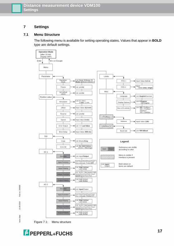
The following menu is available for setting operating states. Values that appear in BOLD type are default settings.
Figure 7.1: Menu structure
Operation Mode(after 10 min Display OFF)
Menu
Parameter
Operation Mode
Set defaultvalues
Freeze
Enter 60 s or Escape
List: Mode 50/Mode 25/Mode 12/Mode 6/Mode 3
List: yes/no
List: yes/no
Limits
POS 1
POS 2
Input: Value (0,3 m)
Input: Value (max. range)
Misc
Language
Display Options
List: English/German
Address Input: Value (126)
List: 0 Degree/ 180 Degree
Position value
Offset
Resolution
Input: Value (0,0 mm)
List: 0.1 mm / 1 mm / 2 mm
SSI
I/O 1
Code
Error Bit
List: Binary/Gray
List: No Valid Values/ Errors + Warnings
Direction
Input Function
List: Input/Output
List: Preset Pos1/Preset Pos2/Key Lock/Laser Pointer/OFF
Input Polarity List: High Active/ Low Active
Output FunctionList: Errors + Warnings/No valid values/Pos1/Pos2/Pos1+Pos2/Speed/Speed Pos1+Pos2
Output Polarity List: High Active/ Low Active
Bold values or items are default
I/O 2
Direction
Input Function
List: Input/Output
List: Preset Pos1/Preset Pos2/Key Lock/Laser Pointer/OFF
Input Polarity List: High Active/ Low Active
Output FunctionList: Errors + Warnings/No valid values/Pos1/Pos2/Pos1+Pos2/Speed/Speed Pos1+Pos2
Output Polarity List: High Active/ Low Active
Reverse List: yes/no
Error Output List: 0 / Last Value
Error Delay Input: Value (500 ms)
Speed Input: Value (5 m/s)
Profibus
List: Input / Output
Menu is visible ifinterface is present
Submenus are visibleaccording to color
Legend
Input Output
Interbus-S
List: SSI / Profibus / SSI + Profibus / Interbus / SSI + Interbus
Baud rate List: 500 kBaud
Bus LED activity
17

Distance measurement device VDM100Settings
Issu
e da
te21
.09.
2010
Par
t no.
206
909
7.2 Description of menu items7.2.1 Parameter
Operation modesThis setting is used to specify the age of the measured value output by the sensor. A measured value age of 50 ms, 25 ms, 12 ms, 6 ms and 3 ms can be configured. An in-crease in the age increases the accuracy of the measurement.
FreezeThe "Freeze" function turns off the noise of the output distance value when the sensor is deactivated. The measured value still remains active, but has a higher hysteresis de-pending on the noise factor.
Set default valuesThis menu item resets all device settings to their default values. If devices are fitted with a PROFIBUS interface, the PROFIBUS address is set to 126.
7.2.2 Position value
ResolutionThis setting defines the resolution of the distance value output at the interfaces (SSI, IN-TERBUS, PROFIBUS). The resolutions 0.1 mm, 1 mm and 2 mm are available for selec-tion. The device display is not influenced by this setting.
OffsetThis value can be used to shift the zero point of the measurement so that several devices with different positions can be preset to the same distances. The absolute sensing range is not modified as a result. Valid offset settings fall within a range of -999.999 m to +999.999 m. The output measured value is calculated from the sum of the absolute mea-sured value and the offset setting. This value is also used to verify the distance limits (See “Position1 / Position2” on page 21.).
ReverseThe reverse setting is used to invert the counting direction. The device displays 0 mm at maximum distance. If the distance decreases, the output value increases. The output measured value is calculated from the difference between the range limit (50 m on VDM100-50 and 150 m on VDM100-150) and the actual measured value.
Operation mode Measured value age Measured value noiseMode 50 50 ms ± 0.5 mm (1 sigma)Mode 25 25 ms ± 0.7 mm (1 sigma)Mode 12 12 ms ± 1.0 mm (1 sigma)Mode 6 6 ms ± 1.4 mm (1 sigma)Mode 3 3 ms ± 2.0 mm (1 sigma)
• If the resulting measured value is negative, the device displays an er-ror, in which case the offset should be increased.
• The offset is also used when the reverse function (See “Reverse” on page 18.) is activated.
18

Distance measurement device VDM100Settings
Issu
e da
te21
.09.
2010
Par
t no.
206
909
SpeedThis menu item defines the speed at which the switch outputs are activated. (See “Speed” on page 20.)
Error outputThis option defines which distance value is issued in the event of an error. A value be-tween ‘0’ and the last valid measured value can be selected. If the ‘last valid value’ setting is selected and the device cannot detect a valid measured value, the value 999.999 m is output.
DelayThis setting defines a delay time that the device waits until signaling an error via the error flag of the bus (SSI, INTERBUS, PROFIBUS) and a correctly configured switching output (See “Errors+Warnings” on page 20.). The error delay is specified in milliseconds.
7.2.3 SSI
CodeThe code of the distance value output by the SSI is defined in this menu. The selection options are digital code and gray code. The error flag is not influenced by the code (See Chapter 10.3.2).
Error bitThis setting defines the behavior of the SSI error bit. The operator can select whether the setting should apply for error messages only (setting "No valid values") or error messag-es and warning messages (setting "Errors and warnings") (See “Error messages” on page 24.). This setting also applies to the collective bit field in the error byte of the PROFIBUS and INTERBUS.
7.2.4 I/O1 and I/O2
Input / OutputThis menu item allows the operator to select the functionality of the relevant I/O pin. The two I/O pins on the device can be configured as an input or an output independently of one another.
Input: FunctionThe functionality of an input can be configured in this submenu, which only appears if the related I/O pin is configured as an input (See “Input / Output” on page 19.).
Preset Pos1 / Preset Pos2If a positive rising edge is increasing at the input pin, this function adopts the most current distance value as a limit value for position 1 or position 2 (See “Position1 / Position2” on page 21.).
Key lockThis function is used to prevent parameter changes via the HMI. A small lock symbol ap-pears on the display in the corresponding submenu. The operator can continue to browse through the menu using the navigation keys.
When configuring via the PROFIBUS, pay attention to the 'Source for limit value position' flag (See Chapter 10.4.)
19

Distance measurement device VDM100Settings
Issu
e da
te21
.09.
2010
Par
t no.
206
909
Laser pointerWith this function, an active input switches on the RLM (Red Laser Marker) as an align-ment aid.
OFFIf this setting is active, a functionality is not assigned to the input. Changes to the state of the input pin are ignored.
Input: polarityThis menu defines the transition between the physical state of the I/O connections and the logical evaluation. For example: An input parameterized as low active is interpreted as inactive (logical '0') if the electrical level is 'High' (Ue > 16 V) and active (logical '1') if the electrical level is 'Low' (Ue < 6 V).
Output: FunctionThe functionality of an output can be configured in this submenu. The menu only appears if the associated I/O pin is configured as an output (See “Input / Output” on page 19.)
Errors+WarningsIf this setting is selected, the output becomes active (logical "1") when an error or warning appears on the display of the device.
No valid valuesIf this setting is selected, the output become active if valid measured values are not avail-able or are output via the interfaces.
Pos1If this setting is selected, the output become active if the (output) distance value is greater than the limit value entered for position 1 (See “Position1 / Position2” on page 21.).
Pos2If this setting is selected, the output becomes active if the (output) distance value is great-er than the limit value entered for position 2 (See “Position1 / Position2” on page 21.).
Pos1+Pos2If this setting is selected, the output becomes active if the (output) distance value falls between the limit values entered for position 1 and position 2 (See “Position1 / Position2” on page 21.).
SpeedIf this output function is selected, the output is activated if the speed measured by the device exceeds the limit value defined under “Speed” on page 19.
The logical status of the input pin is always rated as high active regard-less of the preset polarity of the input pin for the 'Key Lock' function, i.e., the input lock is activated if an actual high is present at the input.
The logical status of the input pin is always rated as high active regard-less of the preset polarity of the input pin for the 'Laser Pointer function, i.e., the laser pointer is activated if an electrical high is present at the input.
20

Distance measurement device VDM100Settings
Issu
e da
te21
.09.
2010
Par
t no.
206
909
Speed pos. 1+2If this setting is selected, the output becomes active if the current speed exceeds the limit value entered under “Speed” on page 19 while the device is outside of the distance val-ues entered for position 1 and position 2 (See “Position1 / Position2” on page 21.).
Output: polarityThis menu defines the transition between the physical state of the I/Os and the logical evaluation. For example: An output parameterized as low active is set to electrical 'High' (Ua = UB - 1 V) when inactive and electrical 'Low' (Ua < 1 V) when active.
7.2.5 Limit values
Position1 / Position2Two position limit values can be defined in these menu items. These values are evaluat-ed by the functions that control the switching outputs (See “Speed” on page 20.).
7.2.6 Other
Language selectionThis setting defines the menu language. The settings German and English are currently available.
Display optionThe orientation of the display can be changed via this menu item. The display can be ro-tated 180° for overhead mounting applications. The key functions are also rotated 180°.
Bus LED activityThis option controls the functionality of the green BUS LED. These LEDs indicate active data transfer to the selected bus. The following selection options are available:
SSI Default setting for devices with SSI
PROFIBUS Default setting for devices with PROFIBUS interface. Does not appear on other devices.
SSI + PROFIBUS For devices with PROFIBUS interface only
INTERBUS Default setting for devices with INTERBUS interface. Does not appear on other devices.
SSI + INTERBUS For devices with INTERBUS interface only.
This submenu does not appear on SSI devices. The BUS LED is set to display SSI activity.
21

Distance measurement device VDM100Settings
Issu
e da
te21
.09.
2010
Par
t no.
206
909
7.3 Operation
Distance and other parameters appear on a display in the front part of the VDM100.The distance and the actual state of the two IO pins are displayed in "operation mode" (See figure 6.7). A white box indicates "low" level and a black box indicates "high" level.Next to this display, there are 4 keys that can be used to navigate in the menu structure. Parameters can also be changed and values can be entered with these keys.Meaning of the keys: - Jump to submenus, confirm value entries
This key works like the ENTER key of a computer keyboard. - Jump out of submenus, undo an entry
This key works like the ESC key of a computer keyboard.
- Scroll up in a menu level - Scroll down in a menu level
Pressing the key takes you to the main menu level. These are all fields that are found under the "MENÜ" field in Chapter 7.1.You can press the and keys to select the appropriate menu item (for example po-sition). Pressing the key again takes you to the first submenu level. Depending on the selection, additional items appear here for selec-tion or the user is prompted to enter a value (for example offset).
Two default values appear in each submenu. These values can be changed. However, please note explicitly that these values must only be changed by persons who have the necessary specialized technical understanding of the effects the change will have.
When numeric values are being entered, the processor checks continuously whether the relevant value is permissible. If an impermissible value is entered, the value cannot be saved and a corresponding message is generated.
If you mistype an entry, press the key several times to delete a number that has been entered or exit the relevant menu.
Negative values are permitted for the offset entry. This is necessary, for example, if the VDM100 had to be fastened at a greater distance but the interface should generate smaller values. If negative offset values that are too large are selected, they will result in a functional failure if the generated distance is less than "zero."
The VDM100 will not display negative distance values. In this case the error bit is set and the output remains set to zero.
Once all the settings have been made, you can return to "Operation Mode" with the key. If no key is pressed in the menu levels for 10 minutes, the display automatically jumps back to "Operation Mode."
22

Distance measurement device VDM100Maintenance and Repair
Issu
e da
te21
.09.
2010
Par
t no.
206
909
7.4 FAQ
Table 7.2: FAQ
8 Maintenance and Repair
MaintenanceObserve the applicable national regulations for maintenance.Basically, the sensor is maintenance free.Nonetheless, check the technical safety of the sensor system at regular intervals, partic-ularly watching out for damage to the housing.Occasionally check the sensor for dirt or other contaminant buildup. To clean the sensor, use a dry or moist soft cloth to wipe the sensor at regular intervals. This action will ensure optimal function.The housing is made of plastic. For this reason avoid contact with acetone and deter-gents containing solvents.RepairIf it seems likely that continued operation is no longer possible without danger, the sensor system must be taken out of operation and protected against unintentionally being placed in operation . Return the device to Pepperl+Fuchs for repair. Interventions and modifica-tions are potentially hazardous, and any warranty and manufacturer's liability shall be-come void.
The error bit comes up frequently during the movement
The measurement beam strays while the reflec-tor is moving
The ERR and TGT LED are on at the same time
The sensor has detected the target, but an addi-tional error is present, for example the reflector distance is greater than the measurement range
23
Distance measurement device VDM100Fault elimination
Issu
e da
te21
.09.
2010
Par
t no.
206
909
9 Fault elimination
Installation Recommendations• The sensor must be firmly mounted. It must not vibrate.• The sensor must not be mounted behind a cover.• The sensor should be mounted so it is protected from the rain.
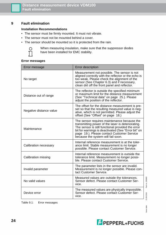
Error messages
Table 9.1: Error messages
When measuring insulation, make sure that the suppressor diodes have been installed for EMC stability.
Error message Error description
No target
Measurement not possible. The sensor is not aligned correctly with the reflector or the echo is too weak. Please check the alignment of the sensor (See Chapter 6.3) and if necessary, clean dirt off the front panel and reflector.
Distance out of range
The reflector is outside the specified minimum or maximum limit for the distance measurement (See “Technical data” on page 25.). Please adjust the position of the reflector.
Negative distance value
The offset for the distance measurement is pre-set so that the resulting measured value is neg-ative, which is not permitted. Please adjust the offset (See “Offset” on page 18.)
Maintenance
The sensor requires maintenance because the transmitting power of the laser is deteriorating. The sensor is still functional provided the error bit for warnings is deactivated (See “Error bit” on page 19.). Please contact Customer Service because the system will fail soon.
Calibration necessaryInternal reference measurement is at the toler-ance limit. Stable measurement is no longer possible. Please contact Customer Service.
Calibration missing Internal reference measurement is outside the tolerance limit. Measurement no longer possi-ble. Please contact Customer Service.
Invalid parameterThe parameter lists in the sensor are invalid. Measurement is no longer possible. Please con-tact Customer Service.
No valid valuesMeasured values are outside the tolerances. Sensor defect. Please contact Customer Ser-vice.
Device errorThe measured values are physically impossible. Sensor defect. Please contact Customer Ser-vice.
24
Distance measurement device VDM100Appendix
Issu
e da
te21
.09.
2010
Par
t no.
206
909
10 Appendix
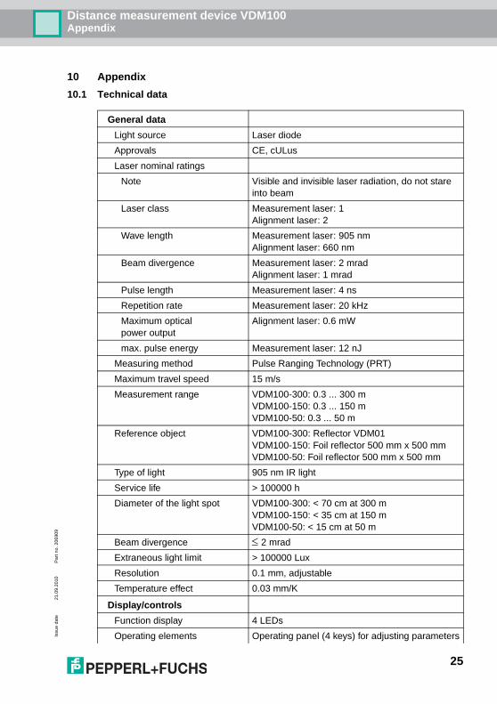
10.1 Technical data
General data
Light source Laser diode
Approvals CE, cULus
Laser nominal ratings
Note Visible and invisible laser radiation, do not stare into beam
Laser class Measurement laser: 1Alignment laser: 2
Wave length Measurement laser: 905 nmAlignment laser: 660 nm
Beam divergence Measurement laser: 2 mradAlignment laser: 1 mrad
Pulse length Measurement laser: 4 ns
Repetition rate Measurement laser: 20 kHz
Maximum optical power output
Alignment laser: 0.6 mW
max. pulse energy Measurement laser: 12 nJ
Measuring method Pulse Ranging Technology (PRT)
Maximum travel speed 15 m/s
Measurement range VDM100-300: 0.3 ... 300 mVDM100-150: 0.3 ... 150 mVDM100-50: 0.3 ... 50 m
Reference object VDM100-300: Reflector VDM01VDM100-150: Foil reflector 500 mm x 500 mmVDM100-50: Foil reflector 500 mm x 500 mm
Type of light 905 nm IR light
Service life > 100000 h
Diameter of the light spot VDM100-300: < 70 cm at 300 mVDM100-150: < 35 cm at 150 mVDM100-50: < 15 cm at 50 m
Beam divergence 2 mrad
Extraneous light limit > 100000 Lux
Resolution 0.1 mm, adjustable
Temperature effect 0.03 mm/K
Display/controls
Function display 4 LEDs
Operating elements Operating panel (4 keys) for adjusting parameters
25

Distance measurement device VDM100Appendix
Issu
e da
te21
.09.
2010
Par
t no.
206
909
Parameterization display Illuminated display for measured value display and parameterization
Electrical data
Operating voltage UB 18 ... 30 V DC
Operating current 250 mA (18 V) ... 150 mA (30 V)
Protection class III (rated voltage 50 V)
Time delay before availability tv < 10 s (-30 °C after 5 min.)
Inputs / Outputs
Switching current 200 mA per output
Input/Output type 2 PNP inputs/outputs, independent configuration, short-circuit protection, reverse polarity protection
Input switching threshold low: Ue < 6 Vhigh: Ue > 16 V
Output switching threshold low: Ua < 1 Vhigh: Ua > UB - 1 V
Measurement accuracy
Measured value output 1 ms
Average measured value age 3 ms, 6 ms, 12 ms, 25 ms, 50 ms, adjustable
Offset max. 2 mm (between two devices)
Absolute accuracy ± 2.5 mm (> 3 m), ± 3.5 mm (0.3 m ... 3 m)
Repeatability < 0.5 mm
Conformity
Standards EN 61326-1:2006; EN 60947-5-2:2007; IEC 60825-1:2007
Ambient conditions
Ambient temperature -10 ... 50 °C (263 ... 323 K)Version /146:-30 ... 50 °C (243 ... 323 K)
Storage temperature -20 ... 70 °C (253 ... 343 K)Version /146:-30 ... 70 °C (243 ... 343 K)
Relative humidity 95%, no condensation
Mechanical data
Degree of protection IP65
Connection M12x1 quick disconnect, 4-pin, standard (supply),M12x1 quick disconnect, 5-pin, B-coded,M12x1 quick disconnect, 5-pin, B-coded,M12x1 quick disconnect, 8-pin, service
26
Distance measurement device VDM100Appendix
Issu
e da
te21
.09.
2010
Par
t no.
206
909
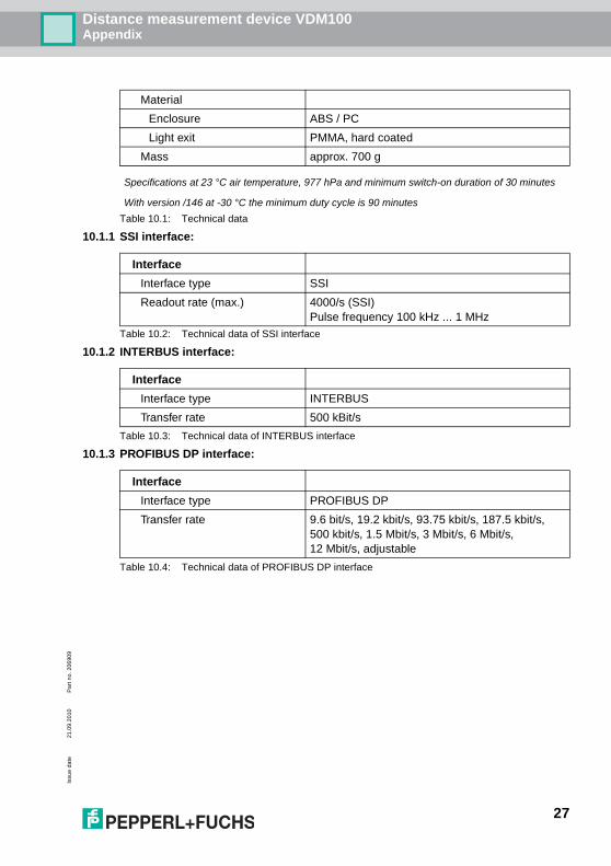
Table 10.1: Technical data
10.1.1 SSI interface:
Table 10.2: Technical data of SSI interface
10.1.2 INTERBUS interface:
Table 10.3: Technical data of INTERBUS interface
10.1.3 PROFIBUS DP interface:
Table 10.4: Technical data of PROFIBUS DP interface
Material
Enclosure ABS / PC
Light exit PMMA, hard coated
Mass approx. 700 g
Specifications at 23 °C air temperature, 977 hPa and minimum switch-on duration of 30 minutes
With version /146 at -30 °C the minimum duty cycle is 90 minutes
Interface
Interface type SSI
Readout rate (max.) 4000/s (SSI)Pulse frequency 100 kHz ... 1 MHz
Interface
Interface type INTERBUS
Transfer rate 500 kBit/s
Interface
Interface type PROFIBUS DP
Transfer rate 9.6 bit/s, 19.2 kbit/s, 93.75 kbit/s, 187.5 kbit/s, 500 kbit/s, 1.5 Mbit/s, 3 Mbit/s, 6 Mbit/s, 12 Mbit/s, adjustable
27

Distance measurement device VDM100Appendix
Issu
e da
te21
.09.
2010
Par
t no.
206
909
10.2 Model numbers
Table 10.5: Model numbers
Photoelectricdistance measurement devices
Sensing range Model number
with SSI Interface 0.3 ... 50 m VDM100-50-SSI
with SSI Interface and expanded Temperature range -30 °C 0.3 ... 50 m VDM100-50-SSI/146
with SSI Interface 0.3 ... 150 m VDM100-150-SSI
with SSI Interface and expanded Temperature range -30 °C 0.3 ... 150 m VDM100-150-SSI/146
with SSI Interface 0.3 ... 300 m VDM100-300-SSI
with INTERBUS interface 0.3 ... 50 m VDM100-50-IBS
with INTERBUS interface 0.3 ... 150 m VDM100-150-IBS
with INTERBUS interface 0.3 ... 300 m VDM100-300-IBS
with PROFIBUS interface 0.3 ... 50 m VDM100-50-P
with PROFIBUS interface and expanded Temperature range -30 °C 0.3 ... 50 m VDM100-50-P/146
with PROFIBUS interface 0.3 ... 150 m VDM100-150-P
with PROFIBUS interface and expanded Temperature range -30 °C 0.3 ... 150 m VDM100-150-P/146
with PROFIBUS interface 0.3 ... 300 m VDM100-300-P
28

Distance measurement device VDM100Appendix
Issu
e da
te21
.09.
2010
Par
t no.
206
909
10.3 Description of Interfaces
10.3.1 General
• Serial data transfer is provided for all interfaces.• The valency for LSB can be adjusted in the menu to values 0.1 mm / 1mm / 2 mm
(See “Resolution” on page 18.). The default is 1 mm.
10.3.2 SSI
A 100 terminating resistor (0.25 ) must be connected between Data+ and Data- on the control computer if the resistor is not already built into the interface card. A screen connection on both sides is recommended.Figure 10.7 shows the pulse diagram of the data transfer. The monoflop time tM is 20 µs and the delay time tv is a maximum of 100 ns.The pulse must be a minimum of 100 kHz (max. period duration T=10 µs).
Data telegram:
Table 10.6: SSI data telegram
Digital code:Error bit Error bit: 0 = no error, 1 = error (see SSI error bit on Page 19)Bit D24 ... D1 Distance value, digitally coded with variable resolution
Gray code:Error bit Error bit: 0 = no error, 1 = error (see SSI error bit on Page 19)Bit D24 ... D1 Distance value, gray coded with variable resolution (e.g. 0.1 mm;
1 mm, 2 mm)24 data bits in the gray code and 1 error bit are transferred. The error bit is transferred uncoded.The code for the distance value can be selected in the menu.
Figure 10.7: Pulse diagram for data transfer
MSB LSB SSIError
Bit Bit Bit Bit Bit Bit Bit Bit Bit Bit Bit Bit Bit Bit Bit Bit Bit Bit Bit Bit Bit Bit Bit Bit Bit
D24 D23 D22 D21 D20 D19 D18 D17 D16 D15 D14 D13 D12 D11 D10 D9 D8 D7 D6 D5 D4 D3 D2 D1
Distance value
Clock
Serial data
Monoflop
Data parallel
t mt v
T21 3 4
D24 D23 D1 Error
m
Tp
29

Distance measurement device VDM100Appendix
Issu
e da
te21
.09.
2010
Par
t no.
206
909
10.3.3 INTERBUS
INTERBUS has automatic successor detection. The successor is detected if it has an ac-tive bus when the power is turned on. If the successor does not become active until later, it is not detected automatically. In that case a software reset must be triggered.The shield must be attached on both sides. The input (REMOTE BUS IN) is completely potential-free to the operating voltage and output (REMOTE BUS OUT). The output shield should be laid to PE (ground).If the IN and OUT shields are connected, they must be laid to PE (ground) and a 10 mm² potential compensation must also be laid in parallel.
Data telegram:
Table 10.8: INTERBUS data telegram
4 bytes are transferred digitally (1 error byte and 3 measurement value bytes). Bit 0 in the error byte is used as the error bit.
10.3.4 PROFIBUS DP
The last PROFIBUS node must be terminated with terminating resistors. To do this, screw the PROFIBUS termination (see Chapter 4.3) onto the termination connection.An address can be allocated via the PROFIBUS interface or the display. The default ad-dress is 126.
Data telegram:
Table 10.9: PROFIBUS data telegram
The shield must be attached on both sides. 5 bytes are transferred digitally (3 measured value bytes (M_low, M_middle, M_high), 1 error byte and 1 input byte). Bit 0 in the error byte is used as the error bit. The input byte is switched as follows (switching outputs of the VDM100): Bit 0 = IO1 (= pin 4) and bit 1 = IO2 (= pin 2).
Byte 0 Byte 1 Byte 2 Byte 3
Bit Bit Bit Bit Bit Bit Bit Bit Bit Bit Bit Bit Bit Bit Bit Bit Bit Bit Bit Bit Bit Bit Bit Bit Bit Bit Bit Bit Bit Bit Bit Bit
7 0 7 0 7 0 7 0
Error Distance high Distance middle Distance low
The VDM100 supports the PROFIBUS functionality "Freeze mode" whereby the measured value in the bus is no longer updated. This func-tionality should not be confused with the "Freeze" option in the VDM100 menu (see 1.2)
Low byte Middle byte High byte Error byte Inputs
0 1 2 3 3
Bit Bit Bit Bit Bit Bit Bit Bit Bit Bit Bit Bit Bit Bit Bit Bit Bit Bit Bit Bit Bit Bit Bit Bit Bit Bit Bit Bit Bit Bit Bit Bit Bit Bit Bit Bit Bit Bit Bit Bit
7 0 7 0 7 0 7 0 7 0
Distance low Distance middle Distance high ErrorError: Bit 0 = 1
Inputs:Bit 0 = IO1Bit 1 = IO2
30

Distance measurement device VDM100Appendix
Issu
e da
te21
.09.
2010
Par
t no.
206
909
10.3.5 Error byte for PROFIBUS and INTERBUS
The error byte is composed of individual error bits, which specify the status of the sensor. Please refer to the following table for details of bit assignment. A more detailed descrip-tion of the error states is included in Section “Error messages” on Page 24.
Table 10.10: Error byte for PROFIBUS and INTERBUS
Bit Meaning
0Collective fault: If one of the following bits 1 - 6 ("No valid values") or bits 1 - 7 ("Error+Warnings") is set, this bit is set in line with the SSI error bit setting (see Page 19).
1 Fault: "No target"
2 Fault: "No valid values" or "Sensor faulty"
3 Fault: "Distance out of range"
4 Fault: "Calibration missing" or "Calibration necessary"
5 Fault: "Negative distance value"
6 Fault: "Invalid parameter"
7 Warning: "Maintenance"
31
Distance measurement device VDM100Appendix
Issu
e da
te21
.09.
2010
Par
t no.
206
909
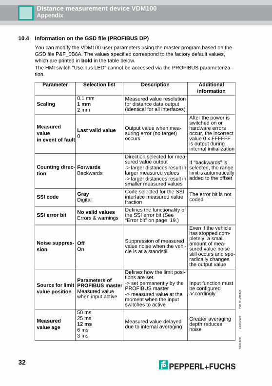
10.4 Information on the GSD file (PROFIBUS DP)
You can modify the VDM100 user parameters using the master program based on the GSD file P&F_0B6A. The values specified correspond to the factory default values, which are printed in bold in the table below.The HMI switch "Use bus LED" cannot be accessed via the PROFIBUS parameteriza-tion.
Parameter Selection list Description Additional information
Scaling0.1 mm1 mm2 mm
Measured value resolution for distance data output (identical for all interfaces)
Measured value in event of fault
Last valid value0
Output value when mea-suring error (no target) occurs
After the power is switched on or hardware errors occur, the incorrect value 0 x FFFFFF is output during internal initialization
Counting direc-tion
ForwardsBackwards
Direction selected for mea-sured value output-> larger distances result in larger measured values-> larger distances result in smaller measured values
If "backwards" is selected, the range limit is automatically added to the offset
SSI code GrayDigital
Code selected for the SSI interface measured value fraction
The error bit is not coded
SSI error bit No valid valuesErrors & warnings
Defines the functionality of the SSI error bit (See “Error bit” on page 19.)
Noise suppres-sion
OffOn
Suppression of measured value noise when the vehi-cle is at a standstill
Even if the vehicle has stopped com-pletely, a small amount of mea-sured value noise still occurs and spo-radically changes the output value
Source for limit value position
Parameters of PROFIBUS masterMeasured value when input active
Defines how the limit posi-tions are set.-> set permanently by the PROFIBUS master-> measured value at the moment when the input switches to active
Input function must be configured accordingly
Measured value age
50 ms25 ms12 ms6 ms3 ms
Measured value delayed due to internal averaging
Greater averaging depth reduces noise
32

Distance measurement device VDM100Appendix
Issu
e da
te21
.09.
2010
Par
t no.
206
909
Offset [mm]
-999.999mm … +999.999mm
Default setting 0
Shifts the zero point of the device by the required value in a positive or nega-tive direction.Always entered in mm, regardless of the mea-sured value scaling.
If the sum of the measured value and the offset is negative, the error bit is set and the output value remains zero.
IO1 configura-tion
InputOutput
Functionality of the IO1 pin (pin 4)
I1 polarity Low activeHigh active
Input polarity low or high active
Low: Ue < 6 VHigh: Ue > 16 V
I1 function
Selection of input function
Set position 1 At the active edge, the cur-rent measured value is adopted as pos1/2Set position 2
Key lockThe operating elements are locked if the input is active
Marking laserThe marking laser is switched on permanently if the input is active
No function
O1 polarity Low activeHigh active
Output polarity low or high active
Low: Ua < 1 VHigh: Ua > UB - 1 V
O1 function
Output active if
Errors & Warnings Errors or warnings
Measured value invalid Invalid measured value
Location > position 1 Position 1 exceeded
Location > position 2 Position 2 exceeded
between Pos1 and Pos2
Pos1<measured value<Pos2
Maximum speed exceeded
the limit speed was exceeded at any point.
Max. V outside[Pos 1, Pos 2]
the limit speed is exceeded out of [Pos1, Pos2]
Identical function are available for the IO2=Pin 2
Limit value position 1/2 [mm]
0 … 999.999mm
Default settingP1 = 300 mmP2 = 150.000 mm
Independent default values are compared internally with the output value (= measured value + offset) and the result of the com-parison is applied to the outputs.
Positive values per-mitted only!
Parameter Selection list Description Additional information
33

Distance measurement device VDM100Appendix
Issu
e da
te21
.09.
2010
Par
t no.
206
909
Table 10.11: Information on the GSD file
Limit speed [0.1 m/s]
1 ... 150
Limit value specification for internal speed measure-ment. The result of the comparison can be applied to the outputs and also linked to the limit positions.
Corresponds to 0.1 ... 15.0 m/s
Error delay [ms]
0 ... 9999Default setting 500 ms
Delay in the signalization of a measurement error via the interface error bits or the correctly configured output
Language selection dis-play
GermanEnglish
Display option
0 degrees Also rotates the keyboard function 180°180 degrees Rotates the image on the
device display 180°
Defaultsetting
Default setting Resets all parameters to their default settings
Sets the PROFI-BUS address to 126
Customer setting
The values set via PROFI-BUS parameterization are adopted when the PROFI-BUS activates the device.
The PROFIBUS overwrites the device settings modified via the HMI.
Parameter Selection list Description Additional information
34

Dat
e of
issu
e09
/21/
2010
Par
t No.
206
909
With regard to the supply of products, the current issue of the following document is applicable:The General Terms of Delivery for Products and Services of the Electrical Industry, published by the Central
Association of the Electrical Industry (Zentralverband Elektrotechnik und Elektroindustrie (ZVEI) e.V.)in its most recent version as well as the supplementary clause: "Expanded reservation of proprietorship"

Subject to modificationsCopyright PEPPERL+FUCHS • Printed in Germany
www.pepperl-fuchs.com
Worldwide HeadquartersPepperl+Fuchs GmbH68307 Mannheim · GermanyTel. +49 621 776-0E-mail: [email protected]
USA HeadquartersPepperl+Fuchs Inc.Twinsburg, Ohio 44087 · USATel. +1 330 4253555E-mail: [email protected]
Asia Pacific HeadquartersPepperl+Fuchs Pte Ltd.Company Registration No. 199003130ESingapore 139942Tel. +65 67799091E-mail: [email protected]
FACTORY AUTOMATION – SENSING YOUR NEEDS
DOCT-1452C 20690906/2010